Embed Size (px)
Citation preview

Company
LOGO
Technology and Application of Laser Tracker
in Large Space Measurement
Yang Fan, Li Guangyun, Fan Baixing
IWAA2014 in Beijing, China
Zhengzhou Institute of Surveying and Mapping

主要内容
5 Summary
4 Example and application
3 Three dimensional adjustment
2 Accuracy analysis of Laser Tracker
1 Introduction

1 Introduction

1 Introduction
In recent years, with the development of modern industry, especially
the rapid development of manufacturing industry, the 3D precision
measurements for all kinds of large-scale engineering or large pieces of the
structures appeared, including measurements about position, attitude and
shape detection etc.
At the same time, many new problems appeared in large scale
measurements, and we need the knowledge of several disciplines to solve
them, such as geodetic, engineering survey and instruments etc.
The characteristics of this kind of works is large scale, high precision, on-
site measurement, dynamic measurement and attitude measurement, the
traditional CMM can not meet these requirements, so large scale coordinate
measurement technology appeared.

1 Introduction
Fixture measuring

1 Introduction
Tailcone measuring of spacecraft
1 Introduction
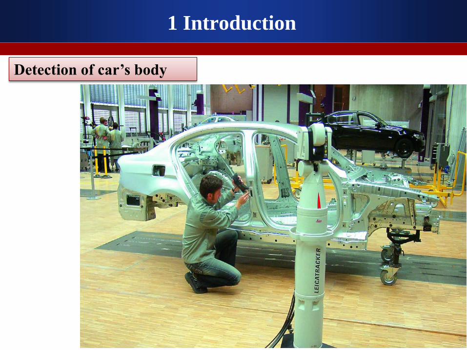
Detection of car’s body

1 Introduction
The above cases can be measured by single station of laser
tracker.
But some large scale projects, can not be measured by
single station.
Based on observation of distance and angles, we can:
1、Calculate X, Y, and Z parameters of targets.
2、Calculate attitude parameters.
3、Reflect the space geometric information of the targets
(relation between points, lines, and surfaces)

1 Introduction
Large hydropower station measuring

1 Introduction
Detection of production line

Accelerator alignment
1 Introduction

1 Introduction
To the large scale projects which can not be measured by
single station, we can use the method of:
So, we should find a method to transform the points’
coordinates of each station to a unified coordinate
system.
The method is three dimensional adjustment.
Free station and
Multi-station match (by common points)

2 Accuracy analysis of Laser Tracker

2 Accuracy analysis of Laser Tracker
The measuring errors of laser tracker is mainly including angle errors and
distance error.
The purpose of accuracy analysis is :
Reflect the error source of laser tracker
Provide theoretical evidence for the weight of
observations in 3D adjustment
X
Y
ZP
S
Hz
V
Problem

Leica AT901-B for example:
15μm+6μm/mm
0.5μm/m, 20m;
10μm, 20m
s
s
m s
m s
15μm+6μm/mpm
80mS
Angle accuracy:
Distance accuracy:
Coordinate accuracy:
Range:
Two problems:
(1) What is relationship between the angle accuracy expression of μm and ″?
(2) Why is the angle accuracy equal to coordinate accuracy?
2 Accuracy analysis of Laser Tracker
Problem

1、Angle error
mm
S
(1)theoretical accuracy
The equation from μm to ″
S
(m) 1 5 10 20 30 40 50 60 70 80
error
(″) 4.3 1.9 1.6 1.4 1.3 1.3 1.3 1.3 1.3 1.3
2 Accuracy analysis of Laser Tracker
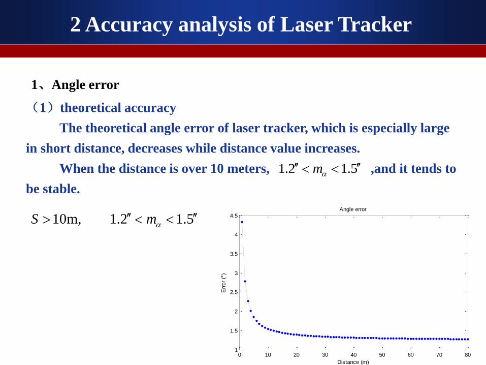
(1)theoretical accuracy
The theoretical angle error of laser tracker, which is especially large
in short distance, decreases while distance value increases.
When the distance is over 10 meters, ,and it tends to
be stable.
10m, 1.2 1.5S m
0 10 20 30 40 50 60 70 801
1.5
2
2.5
3
3.5
4
4.5
Distance (m)
Err
or
(″)
Angle error
2 Accuracy analysis of Laser Tracker
1、Angle error
1.2 1.5m
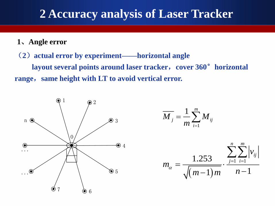
(2)actual error by experiment——horizontal angle
layout several points around laser tracker,cover 360°horizontal
range,same height with LT to avoid vertical error.
1 2
3
4
5
67
...
n
O
...
1
1 m
j ij
i
M Mm
1 11.253
11
n m
ij
j i
v
mnm m
2 Accuracy analysis of Laser Tracker
1、Angle error

1、Angle error
(2)actual error by experiment——horizontal angle
RMS 0.78(0.40)
Horizontal error
of each point
P1 P2 P3 P4 P5
0.53(0.30) 0.62(0.41) 0.46(0.34) 0.67(0.42) 0.53(0.70)
P6 P7 P8 P9 P10
0.44(0.23) 0.69(0.63) 0.69(0.24) 0.64(0.77) 0.61(0.18)
Single face
error
Face I 0.92(0.47)
Face Ⅱ 0.77(0.59)
1)The distance from points to LT is 3.6m ~ 6.9m,in this range the theoretical error
is 1.7″~ 2.1″,so the actual error is lower than theoretical .
2)The two-face error is 0.59″(leveling 0.43″),lower than face I 0.92″(0.47″)and face II 0.77″(0.59″).
2 Accuracy analysis of Laser Tracker

1、Angle error
(2) actual error by experiment——vertical angle
layout several points in front of laser tracker in a vertical line on the
wall,cover ±45°vertical range.
1
1 m
j ij
i
M Mm
1 11.253
11
n m
ij
j i
v
mnm m
1
2
3
4
...
n
O
...
2 Accuracy analysis of Laser Tracker

1、Angle error
(2) actual error by experiment——vertical angle
1)The two-face vertical error is 0.52″,while single face error is 0.67″(I)and
0.68″(Ⅱ). Both are lower than theoretical value and two-face error is lower than
single face.
2)its nearly the same accuracy between face I and face II.
theoretical
(″)
Actual error
(″, unleveling/leveling))
Single face error
(″, unleveling/leveling))
I面 Ⅱ面
1(48m) 1.3 0.67(0.59) 0.80(0.90) 0.84(0.74)
2(38m) 1.3 0.53(0.57) 0.76(0.57) 0.72(0.78)
3(28m) 1.3 0.47(0.55) 0.57(0.56) 0.54(0.77)
4(18m) 1.4 0.53(0.41) 0.64(0.54) 0.67(0.55)
5(10m) 1.5 0.50(0.42) 0.73(0.54) 0.64(0.54)
2 Accuracy analysis of Laser Tracker

in space(7m5m3m),layout 11 points,two stations of AT901:
observations from single face I and II.
0
0.02
0.04
0.06
0.08
0.1
0 1 2 3 4 5 6 7 8 9 10 11 12
Co
ord
inate
err
or/
mm
points
单面测量 双面测量
1、Angle error
(3) actual error by experiment——coordinates
2 Accuracy analysis of Laser Tracker

2、distance error
2 Accuracy analysis of Laser Tracker
0.5μm/m, 20m;
10μm, 20m
s
s
m s
m s
Distance accuracy of AT901:
distance(m) 1 5 10 20 30 40 50
angle error(μm) 21 45 75 135 195 255 315
distance error(μm) 0.5 2.5 5 10 10 10 10

conclusion:
Based on the comparison of angle error and distance error, we can get the
conclusion that:
the angle error is the main part of LT measuring errors, and it can be reduced
by two-face observation.
15μm+6μm/mPm m
2 Accuracy analysis of Laser Tracker
2、distance error
So it explains the equation

3 Three dimensional adjustment

3 Three dimensional adjustment
each single coordinate system transform to unified coordinate system:
1、Modeling
ij
ij
ij
iii
iii
iii
ij
ij
ij
ZZ
YY
XX
cba
cba
cba
Z
Y
X
0
0
0
333
222
111
iii
iiiiii
iiiiii
iii
iiiiii
iiiiii
ii
iii
iii
RyRxc
RzRxRzRyRxc
RzRxRzRyRxc
RyRxb
RzRxRzRyRxb
RzRxRzRyRxb
Rya
RzRya
RzRya
coscos
cossinsinsincos
sinsincossincos
cossin
coscossinsinsin
sincoscossinsin
sin
sincos
coscos
3
2
1
3
2
1
3
2
1
X
Y
Z
X'Y'
Z'
ST01
ST02
0
2Rx
0
2Ry
0
2Rz
0
02X
0
02Y
0
02Z
……
STi

3 Three dimensional adjustment
the relationship between observations and coordinates:
2 2
2 arctan
arctan2
ij
ij
ij
ij
ij
ij ij
ij i j i j i j
YHz
X
ZV
X Y
S X X Y Y Z Z
V A x l
Xi
Yi
Zi
P
Sij
Xij
Yij
Zij
Vij
2π-HijO
1、Modeling
1 1 111 11 11 1 1 1( , , , , , , , , , , )m m m
S Hz V S Hz V S Hz V T
n n n mn mn mnV v v v v v v v v v
11 11 11 1 1 1, , , , , , , , ,m m m m m m
TS Hz V S Hz V S Hz V
n n n mn mn mnl l l l l l l l l
1 1 1 1 1 1, , , , , ,T
X X Y Z Rx Ry Rz
minTV PV
1 Tx N A Pl

3 Three dimensional adjustment
2、parameters estimation
1 1 1 1 1 1, , , , , ,T
X X Y Z Rx Ry Rz
3、observations’ weight decision
2 2 2
0 0 0
2 2 2Hz V S
Hz V S
m m mP P P
m m m 、 、
2 1
0 =S W
2 2 1
0 0max 1 2 3r r
i iˆ ˆ , i
, ,
2
00
2 0 1
0
i
i i
P(P )
Based on the coordinate transformation:
1)experiential methods
2)component of variance model
Calculate equations:
Terminate condition of iteration:

4 Example and application

4 Example and application
1、Application
The total length of a new production line in BAOSTEEL is more than 500
m, about 10m wide, and in order to install production equipment, it is necessary
to establish high control network.
X
ST01G1
G2
G3
Gi
Gn
轧辊安装走向东
N
ST11ST05
Gi+1
Y500m
10m

4 Example and application
Measuring on site

4 Example and application
X
ST01G1
G2
G3
Gi
Gn
轧辊安装走向
东
N
ST11ST05
Gi+1
Y
(1)Instrument: Leica AT901-B,CCR1.5″ reflector,72 control points(G1~G72).
(2)In order to control the error accumulation of multi-station method, the
measuring began from middle to both sides, and the coordinate system of first
station was suggested for unified system after adjustment。
Control network survey

4 Example and application
2、 data processing
After 3D adjustment, according to the calculation, the length of production line
was 488m, and there were 72 control points which were used for adjustment. The
RMS of point coordinate is 0.185mm, and the maximum is 0.377mm.
Coordinate error

4 Example and application
Axis errors
2、data processing
0 10 20 30 40 50 60 70 800
0.05
0.1
0.15
0.2
0.25
0.3
0.35
0.4
Point number
Cum
ula
tive e
rrors
[m
m]
Cumulative errors of BAOSTEEL by 3D method based on unleveling status
Mx
My
Mxy
Mz
Mp
(1)The error of each axis is
gradually accumulated from
center to sides.
(2) The accuracy of XY plane is
0.076mm,while the accuracy of
Z axis is 0.167mm,so the error
of Z axis is higher than X axis
and Y axis apparently.
(3)The deviation between each
axis is enlarging sharply with
the increasing of stations and
length.

5 Summary

5 Summary
1、The error of X axis is lower than Y axis, because the network is too narrow
in Y axis ,so that the stability of network in X axis is better than Y.
X
ST01G1
G2
G3
Gi
Gn
轧辊安装走向
东
N
ST11ST05
Gi+1
Y
Method: Add length
constraints in Y direction to
improve accuracy

5 Summary
2、The accumulated error in Z axis is larger than X axis and Y axis,
because of the influence of vertical error. So leveling data can be considered
for adjustment in the 3D model together for restraining accumulated errors
in Z axis.
1S
2S
1v
2v
B
A
P
i
1 2
地面
principle of middle method by total station
, 1 , 1 , 1 , 1 , ,sin sinj j i j ij i j j j i j i jh Z Z S V S V
)(2 wXBKPVV X
TT
equation of elevation between
two points:
condition equation:

Thanks for your attention!