Embed Size (px)
Citation preview

TEHNIČNI P R A V I L N I K
Državnega Prvenstva in Pokalnega prvenstva Razred 3 DP/SP Rotax-MINI MAX Razred 4 DP/SP Rotax-JUNIOR Razred 5 DP/SP Rotax- MAX Razred 6 DP/SP Rotax-DD2 Razred 6 SP Rotax-DD2 Masters 2013 Ljubljana 10.01.2013

Glej SLO dodatek Tehničnega pravilnika RMC 2013
za Državno in pokalno prvenstvo :
SLO DODATEK TEHNIČNEGA PRAVILNIKA RMC 2013
ZA DRŽAVNO IN POKALNO PRVENSTVO 3.0 KART 3.1. OKVIR
Pri Rotax MAX je uporaba sprednjih zavor prepovedana 3.8 MINIMALNA TEŽA ( ŠPORTNI PRAVILNIK RMC 2013)
MINI MAX - Minimalna dovoljena teža 130 kg ,(Vozilo z voznikom merjeno po dirki)
JUNIOR - Minimalna dovoljena teža 145 kg ,(Vozilo z voznikom merjeno po dirki)
MAX - Minimalna dovoljena teža 165 kg ,(Vozilo z voznikom merjeno po dirki)
DD2 - Minimalna dovoljena teža 173 kg ,(Vozilo z voznikom merjeno po dirki)
DD2 MASTER Minimalna dovoljena teža 180kg ,(Vozilo z voznikom merjeno po dirki) 4. GUME : Rotax Miini Max
- Mojo D1, spredaj 4,5 x 10 -5
- Mojo D1 zadaj 6.0 x 11-5
- Mojo W2 spredaj 4.0 x 10⁻⁵
- Mojo W2 zadaj 6.0 x 11-5
Vse gume morajo biti kupljene pri organizatorju, tekmovanja in označene z bar kodo.
8. OLJA – MAZIVA :
- Gorivo kupljeno na bencinski črpalki, maksimalno 98 oktanov
- Za 2% zmes se sme uporabljati samo olje rotax XPS – kart -2 stroke (CIK homologacija
NO.110162/01) kat. Št. 297460 , v menjalnikih se sme uporabljti olje XPS- kart – tec kart gear
oil kat.št. 25113. Za Rotax Mini , Junior, Senior, Max. Olje za DD2 pa olje z oznako XPS kart
tec DD2 kart gear oil kat.št. 25474.
9.0 MOTORJI :
Uporabljajo se lahko samo motorji kupljeni pri pooblaščenem uvozniku – Sportstil Kart d.o.o
in plombirani pri pooblaščenem servisnem centru :
Slovenija : Sportstil Kart d.o.o , Ljubljana
Hrvaška: AKK podravina, Koprivnica
Vsak motor mora imeti potrjen ID karton od serviserja. 9.1 Rotax Junior, Max :
1.1 SKVIŠ : 1.40 +/- 0,06 Junior
1.20 +/- 0,06 Senior 11. VŽIGALNI SISTEM : 11.9 Prepovedana uporaba NGK svečk.

15.1 UPLINJAČ : Za tekmovanje v Sportstil pokalu, organizator pripravi uplinjače, ki jih morajo tekmovalci
žrebati in montirati z vsakim izhodom na stezo (obvezna montaža spodnje dize, ki je določena
v posebnem pravilniku.)
ROTAX MINI MAX: mini diza 150
ROTAX JUNIOR: mini diza 160
ROTAX MAX: mini diza 160
ROTAX DD2: mini diza 185
ROTAX DD2
SKVIŠ : 1.20 +/- 0,06
1.10 SVEČKE: NGK niso dovoljene !
14.1 PRESTAVNO RAZMERJE : Prosta izbira
17.1 UPLINJAČ: glej 15.1
ROTAX MINI MAX
1.10 SKVIŠ: 1.40 +/- 0,06
2.1 RESTRIKTOR: Verzija 2 ni dovoljena ! Kt.št. 267530
PRESTAVNO RAZMERJE : Na motorju 13 zob
UPLINJAČ : enako kot Max 15.1 in DD2 17.1
Ljubljana 10.01.2013

ROTAX MOJO MAX Challenge Technical Regulations 2013
Appendix for 125 Mini MAX and 125 Micro MAX
Version 10.12.2012
9.5 Technical Specification (within the engine seal) for ROTAX kart engine
125 Mini MAX (10 kW) For the engine configuration 125 Mini MAX, everything that is not specified below, latest technical regulation 2011 for engine configuration 125 Junior MAX is valid. It is the responsibility of the competitor to check his equipment (all components outside the engine seal and mentioned below), to assure that his equipment is in line with the technical specification below!
Squish gap 1.1 125 Mini MAX 1,20 mm - 1,80 mm
Authorized distributors organizing a national MAX Challenge for the category 125 Mini MAX may determine a more restrictive squish gap within this tolerance. The squish gap must be measured with a certified slide gauge and by using a 2 mm tin wire. The crankshaft must be turned by hand slowly over TDC (top dead center) to squeeze the tin wire. Recommended 2mm tin wire (ROTAX part no. 580 130). The squish gap must be measured on the left and right side in the direction of the piston pin. The average value of the two measurements counts.

9.6 Technical Specification (outside the engine seal) for ROTAX kart engine 125 Mini MAX (10 kW)
For the engine configuration 125 Mini MAX, everything that is not specified below, the Technical Specification of items 9.2 for engine configuration 125 Junior MAX is valid. It is the responsibility of the competitor to check his equipment (all components outside the engine seal and mentioned below), to assure that his equipment is in line with the technical specification below!
Intake restrictor 2.1 2.2
Authorized distributors organizing a national MAX Challenge for the category 125 Mini MAX may determine which intake restrictor must be used. Version 1 The intake restrictor (ROTAX part no. 267 535) must be fitted between the carburetor flange and the carburetor. The intake restrictor must show an inner diameter of 19,0 +0,0/-0,2 mm. The intake restrictor must show a blue anodized surface. Version 2 The intake restrictor (ROTAX part no. 267 530) must be fitted into the carburetor flange. The intake restrictor must show an inner diameter of 19,0 +0,2/-0,2 mm. The intake restrictor must show 4 fins in the inlet bore.
Exhaust system 3.1 3.2 3.3
The exhaust restrictor (ROTAX part no. 273 972) must be used instead of the original exhaust socket (fitted to the cylinder). The exhaust restrictor must show an inner-diameter of 22,0 +0,2/-0,2 mm. Exhaust steel mat is an allowed option.
Noise emissions 4.1 4.2
Noise isolating mat (see illustration exhaust system) has to be replaced by a original ROTAX spare part, if the noise emission is exceeding 90 dB (A). Noise emission measuring procedure: The measuring place has to be at section of the track where the engine is operated under full load and at a range between 9.000 and 10.000 rpm. The microphone has to be installed 1 meter above the level of the track in a rectangular angle to the track. The distance between the microphone and the kart on

the ideal line on the track has to be 7,5 meters. The kart has to be operated under full load at the ideal line on the track.
9.7 Technical Specification (within the engine seal) for ROTAX kart engine 125 Micro MAX (5 kW)
For the engine configuration 125 Micro MAX, everything that is not specified below, the Technical Specification of items 9.1 for engine configuration 125 Junior MAX is valid.
Squish gap 1.1 125 Micro MAX 2,40 mm - 2,70 mm
1.2
Authorized distributors organizing a national MAX Challenge for the category 125 Micro MAX may determine a more restrictive squish gap within this tolerance. To achieve the defined squish gap, a spacer (ROTAX part no. 626 420, same shape as a cylinder base gasket) with a thickness of 1,25 mm plus the different required base gaskets must be used. The squish gap must be measured with a certified slide gauge and by using a 3 mm tin wire. The crankshaft must be turned by hand slowly over TDC (top dead center) to squeeze the tin wire. Recommended 3mm tin wire (ROTAX part no. 580 132). The squish gap must be measured on the left and right side in the direction of the piston pin. The average value of the two measurements counts.
9.8 Technical Specification (outside the engine seal) for ROTAX kart engine 125 Micro MAX (5 kW)
For the engine configuration 125 Micro MAX, everything that is not specified below, latest technical regulation 2012 for engine configuration 125 Junior MAX is valid. It is the responsibility of the competitor to check his equipment (all components outside the engine seal and mentioned below), to assure that his equipment is in line with the technical specification below!
Exhaust restrictor 2.1 2.2
The exhaust restrictor (ROTAX part no. 273 972) must be used instead of the original exhaust socket (fitted to the cylinder). The exhaust restrictor must show an inner-diameter of 22,0 +0,2/-0,2 mm.
Carburetor 3.1
The spacer (pos. 1, see illustration below, ROTAX part no. 251 730) must be fitted in the carburetor to limit the opening of the throttle.

3.2 3.3
The length of the spacer has to be 38,0 +/-0,2 mm. The tolerance gauge must not be abled to turn around (opening limit of carburetor slide)!
3.4 3.5 3.6
The position of the cap of the carburetor must be fixed by means of the fixation plate (pos. 1 see illustration below, ROTAX part no. 251 790, see attached picture). The cap of the carburetor has to be screwed completely on to the carburetor. Only one rubber gasket is allowed to be used in the carburetor cap.

Radiator 4.1 4.2 4.3
A specific "Micro MAX" radiator (ROTAX part no. 295 924 or 295 923) must be used instead of the original radiator. Radiator must be mounted with all components similar to the illustration version 2 or 3 for the 125 MAX engine. (see item 18.8 of the technical regulations 2013). Cooling area: height = 280 - 300 mm width = 58 - 62 mm thickness of radiator = 30 - 34 mm
Exhaust system 5.1 5.2 5.3
The specific "Micro MAX" exhaust system must be used instead of the original exhaust system (see illustration below). The inner diameter of the 90° tube at the end of the silencer must be 15 +/- 0,30 mm. No exhaust leakage allowed (no signs of oil). Exhaust must be sealed with silicone.

5.4
Additional to the standard isolation mat a special steel isolation mat of the square dimension of 165 +10 mm is legal (not mandatory) to be assembled underneath the standard isolation mat as in following illustration (ROTAX part no. of kit 297983).
Clamp (1) must be fitted at a distance of 18+/-2mm,
measured from the end of the tube.
Clamp (2) must be fitted at the end area of the steel
isolation mat.
10-12mm is a specification for assembly purpose only!
Both clamps are mandatory.
Noise emissions 6.1 6.2
Noise isolating mat (see illustration exhaust system) has to be replaced by a original ROTAX spare part, if the noise emission is exceeding 90 dB (A). Noise emission measuring procedure: The measuring place has to be at section of the track where the engine is operated under full load and at a range between 8.000 and 9.000 rpm. The microphone has to be installed 1 meter above the level of the track in a rectangular angle to the track. The distance between the microphone and the kart on the ideal line on the track has to be 7,5 meters. The kart has to be operated under full load at the ideal line on the track.

APPROVED

ROTAX MOJO MAX Challenge
Technical Regulations 2013
(The Technical Regulations 2013 replace the Technical Regulations 2012)
Version 10.12.2012
Note:
Note:
Rules written in 10 points are valid for national RMC's only
Rules written in 12 points are valid for national RMC's, IRMCE's and RMCGF
1. Categories:
Karts used in the ROTAX MOJO MAX Challenge (RMC), ROTAX MOJO MAX Challenge
GRAND FINAL (RMCGF) and International ROTAX MOJO MAX Challenge Events (IRMCE) like
the ROTAX MOJO MAX EURO Challenge are divided into the following groups:
● ROTAX 125 Junior MAX
● ROTAX 125 MAX/MASTERS
● ROTAX 125 MAX DD2/MASTERS
(cylinder capacity 125 cc)
(cylinder capacity 125 cc)
(cylinder capacity 125 cc, 2-speed)
2. Amount of equipment:
For each race event (from non-qualifying practice to the final) maximum following
amount of equipment is allowed: 1 chassis
2 sets of dry tires + 1 front + 1 rear spare tire
2 sets of wet tires + 1 front + 1 rear spare tire
2 engines
3.
Kart:
3.1 Chassis:
125 Junior MAX- and 125 MAX classes
For national RMC's any chassis sanctioned by an authorized ROTAX distributor is
allowed.
Chassis tubing : round tubing only.
Maximum diameter of rear axle = 50 mm, minimum wall thickness according to CIK-
FIA rules.
At IRMCE and RMCGF chassis with a valid CIK-FIA homologation only are allowed.
Any brake system must have a valid CIK-FIA homologation. Front brakes are not
allowed In the 125 Junior MAX class.
Front brakes are allowed in 125 MAX class only but may be forbidden by the
authorized distributor or by a race promoter in accordance with the authorized
distributor.

125 MAX DD2 / DD2 MASTERS
For all national RMC, IRMCE and the RMCGF 125 MAX DD2 /DD2 MASTERS
classes, chassis approved by ROTAX only are allowed to be used (approved chassis
will be listed at the web page: www.maxchallenge-rotax.com).
Chassis must be designed according to CIK-FIA rules for shifter classes (front- and
rear brakes mandatory).
Any brake system must have a valid CIK-FIA homologation.
ROTAX rear tire protection system is mandatory to be used. Either old 2 tube version
or latest 3 tube version, third tube might be mounted above or below the 2 main
tubes. No part shall be added or removed from original content (except safety wire as
well as number plate with support).
Only orange or red ROTAX original tyre-protection rollers are allowed to be used.
3.2 Bodywork
125 Junior MAX- and 125 MAX/MAX MASTERS classes
In accordance with regulations of national Federations or CIK-FIA.
At RMCGF and IRMCE bodywork with current CIK-FIA homologation validity only is
allowed, including the rear wheel protection system.
125 MAX DD2 / DD2 MASTERS class
In accordance with regulations of national Federations or CIK-FIA.
At RMCGF and IRMCE bodywork with current CIK-FIA homologation validity only is
allowed. Only the current ROTAX rear wheel protection system is allowed.
4. Tires
At all RMC, IRMCE following tires only are allowed:
Dry (slick) tires: MOJO Type: D1, D2 or D3
Front: 4.5 x 10.0 - 5 Rear: 7.1 x 11.0 -
5
Wet tires: MOJO Type: W2
Front: 4.0 x 10.0 - 5 Rear: 6.0 x 11.0 -
5
At RMCGF following tires only are allowed

125 Junior MAX
Dry (slick) tires: MOJO Type: D1
Front: 4.5 x 10.0 - 5 Rear: 7.1 x 11.0
- 5
Wet tires: MOJO Type: W2
Front: 4.5 x 10.0 - 5 Rear: 6.0 x 11.0
- 5
125 MAX/Masters
Dry (slick) tires: MOJO Type: D2
Front: 4.5 x 10.0 - 5 Rear: 7.1 x 11.0
- 5
Wet tires: MOJO Type: W2
Front: 4.5 x 10.0 - 5 Rear: 6.0 x 11.0
- 5
125 MAXDD2
Masters
Dry (slick) tires: MOJO Type: D3
Front: 4.5 x 10.0 - 5 Rear: 7.1 x 11.0
- 5
Wet tires: MOJO Type: W2
Front: 4.5 x 10.0 - 5 Rear: 6.0 x 11.0
- 5
Strictly no modifications or tire treatment allowed.
Marked direction of rotation must be adhered to for all tires.
If tires are checked for modification we recommend Mini-RAE lite equipment.
5. Data acquisition:
This system, with or without a memory, may permit only the reading/recording of: the engine
revs (by induction on the sparkplug HT cable), two indications of temperature, the speed
of one wheel, an X/Y acceleration, lap times and position ( via GPS system)

6. Composite materials:
Composite materials (carbon fiber etc.) are banned except for the seat and the floor tray.
Alloys from different metals/substances are not considered as composite materials (for
example brake disks).
7. Safety of equipment
For RMCGF and IRMCE article 3 of CIK-FIA technical regulations apply.
For RMC overalls, helmets, kart shoes, gloves and other kind of driver protection must
comply with the regulations of the national Federation or CIK-FIA.
8. Petrol / Oil
Petrol: unleaded commercial quality from petrol station, maximum 98 octane.
Oil: XPS-Karttec 2-stroke oil (CIK homologation no. 110162/01 or )
9. Engines
No sponsor stickers (except ROTAX, BRP, MOJO, XPS) allowed on the engine or at any
other ROTAX engine accessories!
At RMC, RMCGF and IRMCE races, engines which are confirm to the following technical
specification only, are legal to be used.
For national RMC's, engines are allowed to be used only, which have been checked and
sealed by the ROTAX Authorized Distributor of this territory or one of the Service Centers
appointed by the Authorized Distributor.
For national RMC's the ROTAX Authorized Distributor of this territory has to publish the lists
of Service Centers which are legal to check and seal engines.
For IRMCE all ROTAX Authorized Distributors and their Service Centers only are allowed to
check and seal engines.
ROTAX will publish a list of Authorized Distributors and their Service Centers which are
legal to check and seal engines.
For RMCGF ROTAX only is allowed to check and seal engines.
By sealing an engine the ROTAX Authorized Distributors and their Service Centers take
over the responsibility for the conformity of the engine with according to the valid Technical
Specification. Also a brand new engine must be checked according to the Technical
Specification before sealing.
The engines have to be sealed with specific ROTAX engine seals (black anodized
aluminum seal with "ROTAX "-logo and a 6 digit serial number and a barcode).
Further legal seals are:
black anodized aluminum seals with "JAG"-logo and 6 digit serial number

red anodized aluminum seals with "JAG"-logo and 6 digit serial number red anodized seals with "KORRIDAS" and 6 digit serial number blue anodized seals with 6 digit serial number
By means of the steel cable the engine must be sealed on one Allen screw (1) of the intake
flange, on one stud screw (2) of cylinder and one Allen screw (3) of the cylinder head cover
(see attached pictures).
After sealing the engine seal thread must be squeezed using caliper ROTAX part no. 276
110.
(see picture below)
ONLY SEALS WITH BARCODE ARE
LEGAL TO BE USED !
It is not allowed to pass the end of the sealing wire through the seal a second time
(only as in above picture)
At every new sealing of an engine the authority (ROTAX Authorized Distributor or their
Service Centers) that checks and seals an engine is responsible for following indications at
the Engine Identity Card which belongs to the owner of the engine.
● Serial no. of the engine
● Serial no. of the engine seal
1
3
2

● Stamp and signature of the company to be able to detect at scrutineering which
authority has checked and sealed the engine.
At scrutineering the driver has to present
● the engine(s) with the undamaged engine seal(s)
● the Engine Identity Card(s), showing the matching engine serial no.(s), the
matching engine seal no.(s) and the stamp(s) and signature(s) of the authority(ies)
that has (have) checked and sealed the engine(s).
The ROTAX authorized Distributor organizing a national RMC may appoint before every
RMC race a neutral Service Center which will be the only one allowed to re-seal an engine
between scrutineering an the final in the case of an engine failure.
During an IRMCE ROTAX Authorized Distributors and their Service centers are not allowed
to re-seal an engine between scrutineering and the final.
The sealing of engines helps to reduce the times for scrutineering at races as during the
race event just the accessories (carburetor, exhaust, radiator…..) must be checked.
Of course scrutineers can request to open and re-check an engine according to the
Technical Specification, before or after a race or in case of a protest. If an engine seal has
been broken (for which reason ever), the engine has to be checked completely according to
the Technical Specification and must then be re-sealed by an ROTAX authorized Distributor
or one of its Service Centers.
All components outside the seal are part of the responsibility of the competitor to be
in line with the technical regulations.
Neither the engine nor any of its ancillaries may be modified in any way. "Modified" is
defined as any change in form, content or function that represents a condition of difference
from that originally designed. This is to include the addition and/or omission of parts and/or
material from the engine package assembly unless specifically allowed within these rules.
The adjustment of elements specifically designed for that purpose shall not be classified as
modifications, i.e. carburetor and exhaust valve adjustment screws.
The repair of a thread on the crankcase (maximum of one threaded hole per engine)
using a "heli-coil" or similar is allowed (except threads of the pick-up fixation).

Exception: the threads located under the crankcase to fix the crankcase on the engine
mount may be repaired as needed.
Genuine ROTAX components only, that are specifically designed and supplied
for the 125 Junior MAX-, the 125 MAX- and the 125 MAX DD2 engine are legal,
unless otherwise specified.
ANYTHING WHICH IS NOT EXPRESSILY ALLOWED IN THE TECHNICAL
REGULATIONS IS FORBIDDEN.
Internal additions:
No additional material may be added except in the case of engine repairs and shall only
restore the engine or components to original specifications.
The use of thermal barrier coatings/ceramic coatings on or in the engine and on or in the
exhaust system is prohibited.
The use of anti-friction coatings in or on the engine/engine components is prohibited.
Customizing the cylinder head cover by painting is legal
Legal additions:
Chain guard, engine mount, temperature gauge and tachometer/hour meter, inline fuel filter,
catch can mounting brackets and supplemental ignition coil mounting brackets, within the
limits specified in this document.
Non-tech items:
Non-original fasteners, circlips, washers, electrical mass cable, throttle cable housing, fuel
and pulse line (type and size) as well as length of coolant hoses are allowed unless
otherwise specified.”
Note:
When taking any dimensional reading, of the following technical regulation, in the order of
accuracy of 0,1 mm or even more precise, the temperature of the part must
be between +10°C and +30°C.
Note:
Before taking any decision based on this regulation a check for available bulletins is
mandatory.
They can be found under www.maxchallenge-rotax.com
To avoid excessive noise and exhaust emissions ravving the kart in the servicing park is not
allowed (except a short function test).

It is the responsibility of the competitor to check his equipment (all components outside the
engine seal and mentioned below), to assure that his equipment is in line with the technical
specification below!
9.1 Technical Specification (within the engine seal) for ROTAX kart engines 125
Junior MAX (15 kW) & 125 MAX (21 kW).
Squish gap 1.1
1.2
125 Junior MAX
125 MAX
1,20 mm - 1,80 mm
1,00 mm - 1,50 mm
The squish gap must be measured with a certified slide
gauge and by using a 2 mm tin wire. The crankshaft must
be turned by hand slowly over TDC (top dead center) to
squeeze the tin wire.
The squish gap must be measured on the left and right
side in the direction of the piston pin.
The average value of the two measurements counts.
Recommended 2mm tin wire : ROTAX part no. 580 130
Combustion chamber
insert
2.1
2.2
2.3
2.4
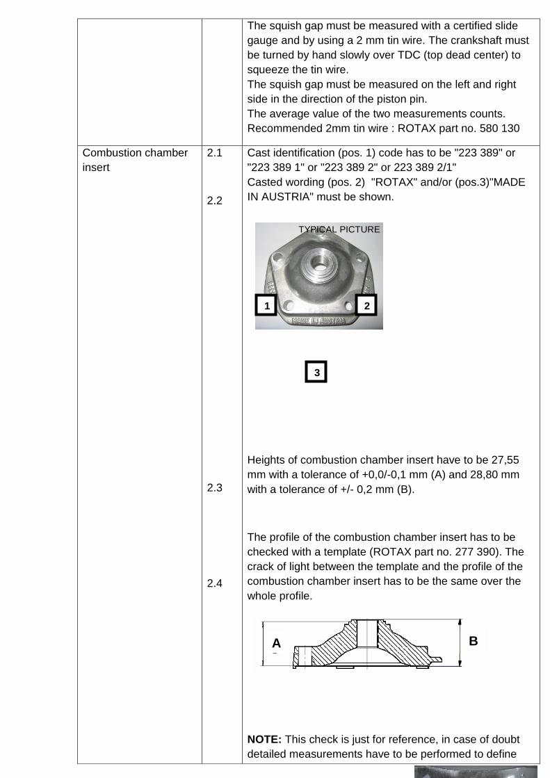
Cast identification (pos. 1) code has to be "223 389" or
"223 389 1" or "223 389 2" or 223 389 2/1"
Casted wording (pos. 2) "ROTAX" and/or (pos.3)"MADE
IN AUSTRIA" must be shown.
Heights of combustion chamber insert have to be 27,55
mm with a tolerance of +0,0/-0,1 mm (A) and 28,80 mm
with a tolerance of +/- 0,2 mm (B).
The profile of the combustion chamber insert has to be
checked with a template (ROTAX part no. 277 390). The
crack of light between the template and the profile of the
combustion chamber insert has to be the same over the
whole profile.
NOTE: This check is just for reference, in case of doubt
detailed measurements have to be performed to define
A B
TYPICAL PICTURE
1
3
2

conformity or non conformity.

Piston with ring assy. 3.1
3.2
3.3
3.4
Original, coated, aluminum, cast piston with one piston
ring. The piston has to show on the inside the cast
wording "ELKO" (1) and "MADE IN AUSTRIA" (2).
Machined areas are: Top end of piston, outside diameter,
groove for the piston ring, bore for the piston pin, inside
diameter at bottom end of piston and some pre-existing
factory removal (3) of flashing at the cut out of the piston
skirt. All other surfaces are not machined and have cast
surface.
Original, magnetic, rectangular piston ring.
Ring height : 0,98 +/- 0,02 mm
Piston ring is marked either with
"ROTAX 215 547" or "ROTAX 215 548".
"Window" type piston as delivered in the early days of
production is no longer legal to be used.
2
1
3
TYPICAL PICTURE
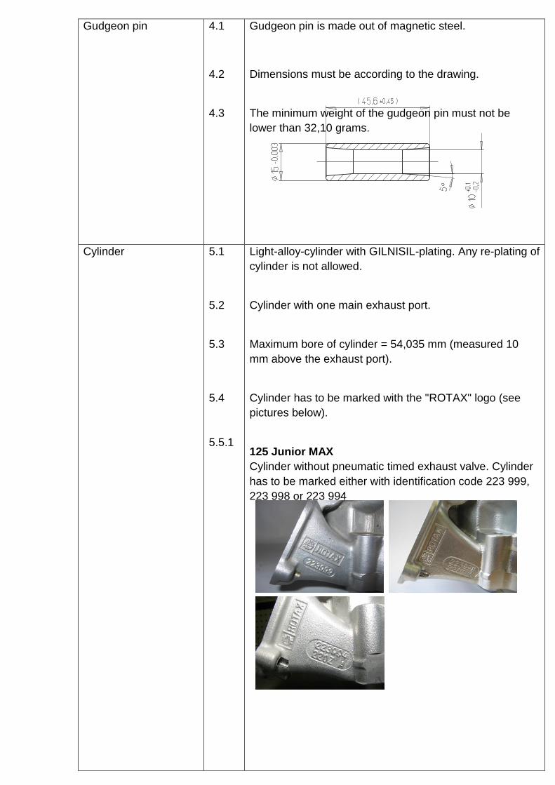
Gudgeon pin 4.1
4.2
4.3
Gudgeon pin is made out of magnetic steel.
Dimensions must be according to the drawing.
The minimum weight of the gudgeon pin must not be
lower than 32,10 grams.
Cylinder 5.1
5.2
5.3
5.4
5.5.1
Light-alloy-cylinder with GILNISIL-plating. Any re-plating of
cylinder is not allowed.
Cylinder with one main exhaust port.
Maximum bore of cylinder = 54,035 mm (measured 10
mm above the exhaust port).
Cylinder has to be marked with the "ROTAX" logo (see
pictures below).
125 Junior MAX
Cylinder without pneumatic timed exhaust valve. Cylinder
has to be marked either with identification code 223 999,
223 998 or 223 994

5.5.2 125 MAX
Cylinder with pneumatic timed exhaust valve. Cylinder has
to be marked either identification code 223 997, 223 996
or 223 993

5.6
5.7.1
Height of cylinder has to be 87 mm -0,05/+0,1 mm.
(measured with a digital caliper)
All transfer ports and passages have cast finish surface
except some removal (done by the manufacturer) of cast
burr at the inlet passage, exhaust port and passages. All
ports have chamfered edges to prevent ring snagging.
Any additional machining is not permitted. The top edge of
exhaust port may show some pre-existing machining from
the manufacturer. The sealing flange for the exhaust
socket may show signs of machining from the
manufacturer.
TYPICAL PICTURE

5.7.2 All ports have chamfered edges.
Any additional machining is not permitted.
On cylinders marked 223 993 and 223 994 the upper edge
of the central boost port may show factory machining.
5.7.3 The sealing flange for the exhaust socket may show either
cast finish surface or signs of machining from the
manufacturer.
TYPICAL PICTURE
TYPICAL PICTURE

5.7.4 The top edge of the exhaust port may show either just a
cast finish surface…
or signs of a CNC machining …
or signs of CNC machining in combination with signs of
manual grinding.
The exhaust port may show partial manual grinding done
by the manufacturer to eliminate minor casting defects
and to eliminate the NIKASIL burr at the end of the
NIKASIL plating.
TYPICAL
PICTURE
TYPICAL
PICTURE
TYPICAL
PICTURE

At cylinders 223 993 and 223 994 exhaust port may show
factory machining all around
5.8
Exhaust port timing
The "exhaust port timing" (distance from the top of the
cylinder to the top of the exhaust port) has to be checked
by means of the template (ROTAX part no. 277 397).
Insert the template into the cylinder, that the template is
touching the cylinder wall and that the finger of the
template is located in the middle of the exhaust port
(highest point).
Move the template upwards, until the finger is touching the
top edge of the exhaust port. Insert a filler gauge between
the top of the cylinder and the template. It must not be
possible to fit the feeler gauge specified below.
125 Junior MAX: 0,90 mm for cylinder 223 999 / 998
1,10 mm for cylinder 223 994
125 MAX: 0,75 mm
At cylinders 223 993 (125 MAX) it is also legal if the
template doesn´t fit in at all.
NOTE: Take care to use the corresponding gauge
(JUN or MAX) of the template for the respective
cylinder!
TYPICAL
PICTURE

5.9
Exhaust valve (125 MAX only)
If the piston is moved in direction top of cylinder and first
time covering completely the exhaust port, it must be
possible to insert the exhaust valve gauge (ROTAX part
no. 277 030) until it stops at the surface of the cylinder (a
feeler gauge of 0,05 mm must not be possible to fit in at
any area around).

Inlet system 6.1
6.2
6.3
6.4
Inlet manifold is marked with the name "ROTAX" and the
identification code "267 915".
Some factory flash removal may be present at the
conjunction of the inside contour and the carburetor stop
mounting face. This is a manual trimming operation
consisting of a small corner break of less than 3 mm in
width. No additional grinding or machining is permitted.
The reed valve assy. is equipped with 2 petal stops and 2
reeds, each having 3 petals.
The thickness of the reeds is 0,6 mm +/- 0,10 mm.
Crankshaft 7.1
7.2
Stroke 54,5 mm +/-0,1 mm
Con rod has to show forged numbers "213", "365" or "367"
on shaft.

7.3
7.4
Shaft of con rod is not machined (copper plated). Grinding
of polishing of shaft of con rod is not permitted.
Crankshaft main bearing 6206 from FAG only is allowed.
(must be marked with code
579165BA or Z-579165.11.KL)

Balance shaft 8.1
8.2
8.3
8.4
8.5
Balance shaft and balance gears must be installed.
Configurations of part no. 237 949 (equal with 237 948)
only is legal.
Surface (1) is not machined and must show cast surface.
Measurement from center of balance shaft to outer
diameter of fly weight of balance shaft at defined length
must not be lower than specified.
The minimum weigh of the dry balance shaft must not be
lower than:
255 grams for balance shaft ROTAX part no. 237 949
(equal with 237 948).
Crankcase
9.1 As supplied by the manufacturer. No
grinding/polishing is permitted in the two main transfer
passages as well as in the crank area.
9.2
Technical Specification (outside the engine seal) for ROTAX kart engines
125 Junior MAX (15 kW) & 125 MAX (21 kW).
It is the responsibility of the competitor to check his equipment (all components outside the
engine seal and mentioned below), to assure that his equipment is in line with the technical
specification below!
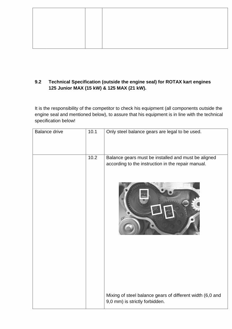
Balance drive 10.1 Only steel balance gears are legal to be used.
10.2 Balance gears must be installed and must be aligned
according to the instruction in the repair manual.
Mixing of steel balance gears of different width (6,0 and
9,0 mm) is strictly forbidden.

Ignition system 11.1
11.2
11.3
11.4
DENSO digital battery ignition, variable ignition timing, no
adjustment necessary and possible.
Race officials may request at any time that the competitor
replaces the ignition coil with another unit provided by the
race administration.
The casting of the ignition coil has to show the following
in casting "129000-" and "DENSO".
Ignition coil must show 3 pins at the terminal.
Connector housing of ignition coil must have either black
or green color.
Version as in attached picture with an extension wire
(number 265571 engraved as in picture) is not legal to
be used any more as of 01.03.2012
The ignition coil has to be fixed by means of 2 original
silent blocks to the gearbox cover. Only in case of
chassis component interference with the original
mounting location of the ignition coil, a supplementary
extension bracket, rigidly constructed and fabricated of
solid metal, of minimum dimensions and attached to the
original case mounting holes, is permitted for mounting of
the coil.
11.5
11.6
11.7
Minimum length of ignition wire (high tension wire)
is 210 mm from outlet of cable at ignition coil to
outlet of cable at spark plug connector
( = the visible length of wire )
Ignition coil must be in working condition ( to be tested in
case of doubt)
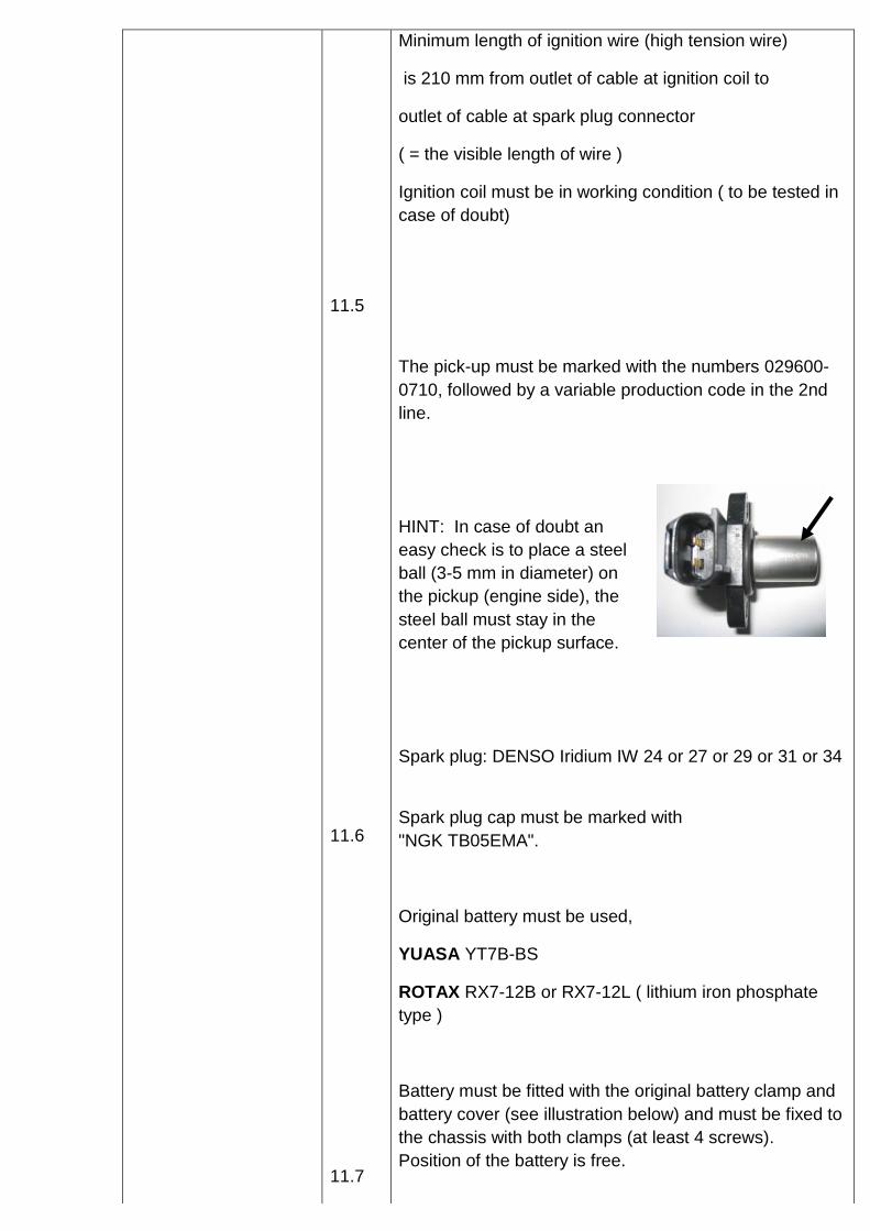
The pick-up must be marked with the numbers 029600-
0710, followed by a variable production code in the 2nd
line.
HINT: In case of doubt an
easy check is to place a steel
ball (3-5 mm in diameter) on
the pickup (engine side), the
steel ball must stay in the
center of the pickup surface.
Spark plug: DENSO Iridium IW 24 or 27 or 29 or 31 or 34
Spark plug cap must be marked with
"NGK TB05EMA".
Original battery must be used,
YUASA YT7B-BS
ROTAX RX7-12B or RX7-12L ( lithium iron phosphate
type )
Battery must be fitted with the original battery clamp and
battery cover (see illustration below) and must be fixed to
the chassis with both clamps (at least 4 screws).
Position of the battery is free.

11.8
11.9
11.10
11.11
11.12
Battery must be mounted with all components as shown
in the illustration below
To fit a second original mass cable (ROTAX part no.
264910) is an allowed option.

11.13

Exhaust valve 12.1
12.2
12.3
12.4
Configuration 125 MAX only!
As supplied by the manufacturer with no modification
allowed. Compression spring must be fitted.
Length of the exhaust valve is 36,5 mm +0,20 mm
/-0,30 mm.
Width of collar is 4,8 mm +/-0,3 mm
Exhaust valve bellow
Only the green colored exhaust valve bellow is legal to
be used (ROTAX part no. 260723)

Centrifugal clutch 13.1
13.2
Dry centrifugal clutch, engagement maximum at 4.000
rpm.
That means, that the kart (without driver) must start to
move latest at an engine speed of maximum 4.000 rpm.
There are two versions of the clutch shoe (element part # 3 on the diagram) and both are legal to be used. The older version of the clutch shoe can be either untreated or nitrated configuration
Engines must be fitted the new needle cage bearing
(item 9) 15X19X17 or plain bearing 15X17X17,6 (for 11
teeth sprocket) as well as new O-Ring 12X2,5 (item 10)
only.
No extra lubrication or additional substance allowed
inside the clutch drum additional to the grease that
originates from lubrication of the needle cage bearing
and enters the
clutch area.

13.3
Picture shows worst case scenario in case grease exits
the bearing area even O-Ring is installed.
Only fixation nut as well as inside of drum show signs of
grease, running surface of clutch is completely dry.
Steel clutch (both versions) and clutch drum must be
within following specifications.
Height of clutch
Minimum: 11,45 mm.
Thickness of clutch shoe
TYPICAL
PICTURE

13.3.1
Measurement has to be done at the 3 open ends of the
clutch shoes, 5 - 10 mm from the machined groove (all
clutch shoes must be completely closed at measurement
- no gap).
No measurement may be below 24,10 mm.
Outer diameter of clutch drum
Diameter has to be measured with a sliding caliper just
beside the radius from the shoulder (not at the open end
of the clutch drum).
Minimum diameter: 89,50 mm.
TYPICAL
PICTURE

13.3.2
Inner diameter of clutch drum
The inner diameter has to be measured with a sliding
caliper. The measurement has to be done in the middle
of the clutch drum (in the contact area of the clutch
drum).
Maximum diameter: 84,90 mm.
Height of sprocket with clutch drum assembly

13.3.3
Minimum height: 33,90 mm


13.3.4
Intake silencer 14.1 Intake silencer with integrated, washable air filter has to
be used with all parts as shown at illustration and has to
be mounted on the support bracket with two screws (in
dry and wet race condition).
Intake silencer tube (pos 2) as well as carburetor socket
(pos 6) are only legal if marked with "ROTAX".
Parts marked with "APRILIA" are no longer legal to be
used.

14.2
14.3
14.4
Intake silencer case bottom is marked on the inside with
the ROTAX part no. 225 015.
Intake silencer case, top is marked on the inside with the
ROTAX part no. 225 025.
Air filter must be installed as shown in illustrations
above.