Embed Size (px)
Citation preview
TEMPERATURE
3415-02
XXXX製品名 HiTESTER
3415-013415
INSTRUCTION MANUAL
3804-50
DIGITAL HiTESTER

iContents
Contents
Introduction ............................................................... 1Verifying Package Contents...................................... 1
Safety Information..................................................... 2Operating Precautions .............................................. 5
Chapter 1 Overview 9
1.1 Product Overview/ Features........................ 9
1.2 Names and Functions of Parts .................. 10
Chapter 2 Measurement 15
2.1 Pre-Operation Inspection .......................... 162.2 Voltage Measurement ............................... 19
2.3 Current Measurement ............................... 202.4 Resistance Measurement.......................... 222.5 Continuity Check ....................................... 23
2.6 Diode Check.............................................. 242.7 Capacitance Measurement ....................... 25
Chapter 3 Additional Functions 27
3.1 Auto Range Function................................. 273.2 Manual Range Function ............................ 28
3.3 Hold Functions .......................................... 283.3.1 Trigger Hold Function..................... 283.3.2 Refresh Hold Function ................... 29
Contentsii
3.4 Recording Function ................................... 303.5 Relative (REL) Display Function ............... 323.6 4-20 mA (0-20 mA) Percentage Display
Function .................................................... 333.7 Bar Graph Display Function...................... 34
3.8 Auto Power Save ...................................... 343.9 Overload Warning ..................................... 353.10 Battery Depletion Alert Function ............... 36
3.11 Communications Function......................... 36
Chapter 4 Power On Options 39
Chapter 5 Specifications 43
5.1 General Specifications .............................. 435.2 Electrical specifications ............................. 455.3 Accuracy ................................................... 46
Chapter 6 Maintenance and Service 51
6.1 Troubleshooting ........................................ 51
6.2 Cleaning .................................................... 536.3 Replacing the Battery and Fuses .............. 536.4 Checking the Instrument Software Version55
6.5 Displaying All On-Screen Items ............... 56
引
0
1
索
4
3
2
1
7
6
5
1
9
8
Thank you for purchasing the HIOKI “Model 3804-50 DIGITALHiTESTER.” To obtain maximum performance from the instru-ment, please read this manual first, and keep it handy for futurereference.
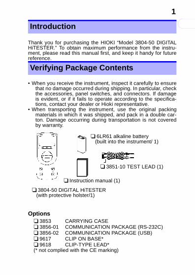
• When you receive the instrument, inspect it carefully to ensurethat no damage occurred during shipping. In particular, checkthe accessories, panel switches, and connectors. If damageis evident, or if it fails to operate according to the specifica-tions, contact your dealer or Hioki representative.
• When transporting the instrument, use the original packingmaterials in which it was shipped, and pack in a double car-ton. Damage occurring during transportation is not coveredby warranty.
Options❏ 3853 CARRYING CASE❏ 3856-01 COMMUNICATION PACKAGE (RS-232C)❏ 3856-02 COMMUNICATION PACKAGE (USB)❏ 9617 CLIP ON BASE*❏ 9618 CLIP-TYPE LEAD*(* not complied with the CE marking)
Introduction
Verifying Package Contents
❏ 6LR61 alkaline battery (built into the instrument/ 1)
❏ 3851-10 TEST LEAD (1)
❏ 3804-50 DIGITAL HiTESTER (with protective holster/1)
❏ Instruction manual (1)
This manual contains information and warnings essential forsafe operation of the instrument and for maintaining it in safeoperating condition. Before using it, be sure to carefully read thefollowing safety precautions.
Safety Information
This instrument is designed to comply withIEC 61010 Safety Standards, and has beenthoroughly tested for safety prior to ship-ment. However, mishandling during usecould result in injury or death, as well asdamage to the instrument. Be certain thatyou understand the instructions and precau-tions in the manual before use. We disclaimany responsibility for accidents or injuries notresulting directly from instrument defects.
Safety Symbols
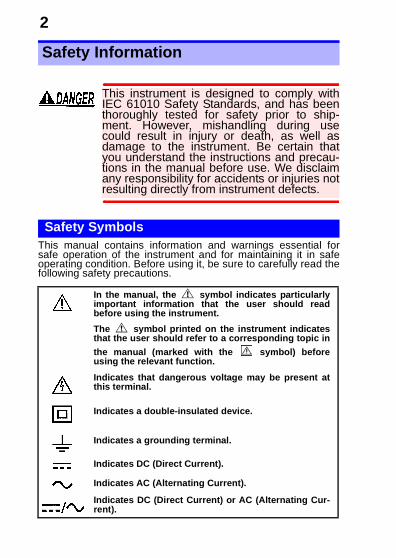
In the manual, the symbol indicates particularlyimportant information that the user should readbefore using the instrument.
The symbol printed on the instrument indicatesthat the user should refer to a corresponding topic in
the manual (marked with the symbol) beforeusing the relevant function.
Indicates that dangerous voltage may be present atthis terminal.
Indicates a double-insulated device.
Indicates a grounding terminal.
Indicates DC (Direct Current).
Indicates AC (Alternating Current).
Indicates DC (Direct Current) or AC (Alternating Cur-rent).
引
0
3
索
4
3
2
1
7
6
5
1
9
8
The following symbols in this manual indicate the relative impor-tance of cautions and warnings.
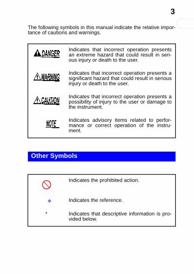
Indicates that incorrect operation presentsan extreme hazard that could result in seri-ous injury or death to the user.
Indicates that incorrect operation presents asignificant hazard that could result in seriousinjury or death to the user.
Indicates that incorrect operation presents apossibility of injury to the user or damage tothe instrument.
Indicates advisory items related to perfor-mance or correct operation of the instru-ment.
Other Symbols
Indicates the prohibited action.
Indicates the reference.
* Indicates that descriptive information is pro-vided below.
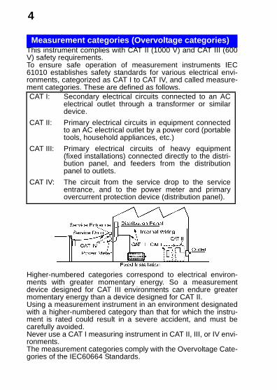
This instrument complies with CAT II (1000 V) and CAT III (600V) safety requirements.To ensure safe operation of measurement instruments IEC61010 establishes safety standards for various electrical envi-ronments, categorized as CAT I to CAT IV, and called measure-ment categories. These are defined as follows.
Higher-numbered categories correspond to electrical environ-ments with greater momentary energy. So a measurementdevice designed for CAT III environments can endure greatermomentary energy than a device designed for CAT II.Using a measurement instrument in an environment designatedwith a higher-numbered category than that for which the instru-ment is rated could result in a severe accident, and must becarefully avoided.Never use a CAT I measuring instrument in CAT II, III, or IV envi-ronments.The measurement categories comply with the Overvoltage Cate-gories of the IEC60664 Standards.
Measurement categories (Overvoltage categories)
CAT I: Secondary electrical circuits connected to an ACelectrical outlet through a transformer or similardevice.
CAT II: Primary electrical circuits in equipment connectedto an AC electrical outlet by a power cord (portabletools, household appliances, etc.)
CAT III: Primary electrical circuits of heavy equipment(fixed installations) connected directly to the distri-bution panel, and feeders from the distributionpanel to outlets.
CAT IV: The circuit from the service drop to the serviceentrance, and to the power meter and primaryovercurrent protection device (distribution panel).
引
0
5
索
4
3
2
1
7
6
5
1
9
8
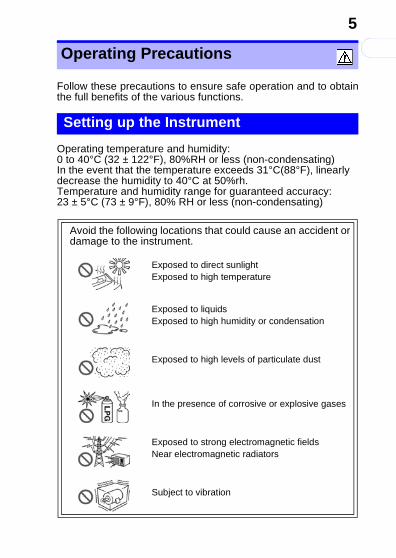
Follow these precautions to ensure safe operation and to obtainthe full benefits of the various functions.
Operating temperature and humidity: 0 to 40°C (32 ± 122°F), 80%RH or less (non-condensating)In the event that the temperature exceeds 31°C(88°F), linearly decrease the humidity to 40°C at 50%rh.Temperature and humidity range for guaranteed accuracy: 23 ± 5°C (73 ± 9°F), 80% RH or less (non-condensating)
Operating Precautions
Setting up the Instrument
Avoid the following locations that could cause an accident or damage to the instrument.
Exposed to direct sunlightExposed to high temperature
Exposed to liquidsExposed to high humidity or condensation
Exposed to high levels of particulate dust
In the presence of corrosive or explosive gases
Exposed to strong electromagnetic fieldsNear electromagnetic radiators
Subject to vibration
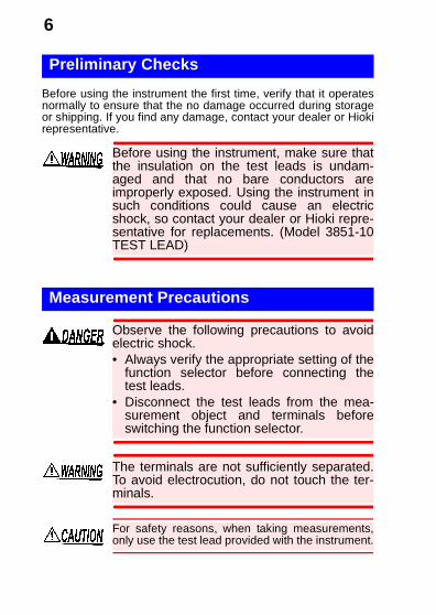
Before using the instrument the first time, verify that it operatesnormally to ensure that the no damage occurred during storageor shipping. If you find any damage, contact your dealer or Hiokirepresentative.
Preliminary Checks
Before using the instrument, make sure thatthe insulation on the test leads is undam-aged and that no bare conductors areimproperly exposed. Using the instrument insuch conditions could cause an electricshock, so contact your dealer or Hioki repre-sentative for replacements. (Model 3851-10TEST LEAD)
Measurement Precautions
Observe the following precautions to avoidelectric shock.• Always verify the appropriate setting of the
function selector before connecting thetest leads.
• Disconnect the test leads from the mea-surement object and terminals beforeswitching the function selector.
The terminals are not sufficiently separated.To avoid electrocution, do not touch the ter-minals.
For safety reasons, when taking measurements,only use the test lead provided with the instrument.
引
0
7
索
4
3
2
1
7
6
5
1
9
8
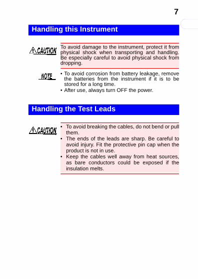
Handling this Instrument
To avoid damage to the instrument, protect it fromphysical shock when transporting and handling.Be especially careful to avoid physical shock fromdropping.
• To avoid corrosion from battery leakage, removethe batteries from the instrument if it is to bestored for a long time.
• After use, always turn OFF the power.
Handling the Test Leads
• To avoid breaking the cables, do not bend or pullthem.
• The ends of the leads are sharp. Be careful toavoid injury. Fit the protective pin cap when theproduct is not in use.
• Keep the cables well away from heat sources,as bare conductors could be exposed if theinsulation melts.

1.1 Product Overview/ Features
引
0
9
索
4
3
2
1
7
6
5
1
9
8
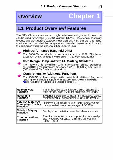
The 3804-50 is a multifunction, high-performance digital multimeter thatcan be used for voltage (DC/AC), current (DC/AC), resistance, continuity,diodes, and electrostatic capacity measurement. Furthermore, this instru-ment can be controlled by computer and transfer measurement data tothe computer when the optional 3856-01/02 is used.
Overview Chapter 1
1.1 Product Overview/ Features
High-performance Handheld DMMThe 3804-50 can display a maximum count of 9999. The basicaccuracy for DC voltage measurement is ±0.09% rdg. ±2 dgt.
Safe Design Compliant with CE Marking StandardsThe 3804-50 is compliant with international safety standards(IEC61010-1 measurement categories CAT II (1000 V) and CAT III(600 V)) and EMC related standards.
Comprehensive Additional FunctionsThe 3804-50 is also equipped with a wealth of additional functionsranging from simple support for measurement to easy analysis.❖See Chapter 3 Additional Functions (page 27)
Refresh Hold Function
The measured value is locked automatically and then stored, even if you let go of the test leads.
Recording Function
Switches the display to maximum measured value, minimum value, average value, or current value.
4-20 mA (0-20 mA) Percentage Display Function
Displays 4-20 mA (0-20 mA) instrumentation sig-nal converted into a percentage of 0-100%.
Relative Display Function Displays the deviation from the reference value.
Communications Function
Permits connection to a computer for data analy-sis. (Requires RS-232C/USB and the optional 3856-01/02.)
1.2 Names and Functions of Parts
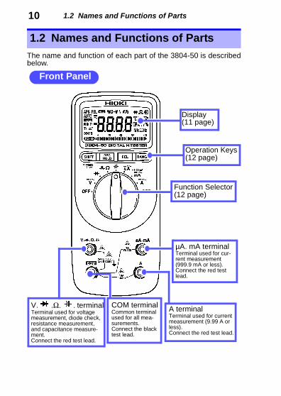
10The name and function of each part of the 3804-50 is describedbelow.
1.2 Names and Functions of Parts
Front Panel
Display(11 page)
Operation Keys(12 page)
Function Selector(12 page)
µA. mA terminalTerminal used for cur-rent measurement (999.9 mA or less).Connect the red test lead.
A terminalTerminal used for current measurement (9.99 A or less). Connect the red test lead.
COM terminalCommon terminal used for all mea-surements. Connect the black test lead.
V. .Ω. . terminalTerminal used for voltage measurement, diode check, resistance measurement, and capacitance measure-ment.Connect the red test lead.
1.2 Names and Functions of Parts
引
0
11
索
4
3
2
1
7
6
5
1
9
8
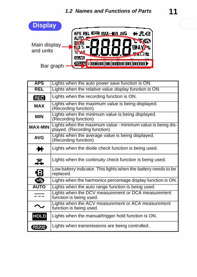
Display
Bar graph
Main display and units
APS Lights when the auto power save function is ON.REL Lights when the relative value display function is ON.
Lights when the recording function is ON.
MAX Lights when the maximum value is being displayed.(Recording function)
MIN Lights when the minimum value is being displayed.(Recording function)
MAX-MIN Lights when the maximum value - minimum value is being dis-played. (Recording function)
AVG Lights when the average value is being displayed. (Recording function)
Lights when the diode check function is being used.
Lights when the continuity check function is being used.
Low battery indicator. This lights when the battery needs to be replaced.
Lights when the harmonics percentage display function is ON.AUTO Lights when the auto range function is being used.
Lights when the DCV measurement or DCA measurement function is being used.Lights when the ACV measurement or ACA measurement function is being used.
Lights when the manual/trigger hold function is ON.
Lights when transmissions are being controlled.
HOLD
1.2 Names and Functions of Parts
12Function Selector
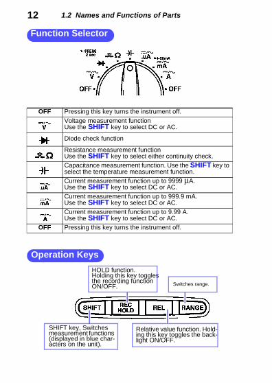
OFF Pressing this key turns the instrument off.
Voltage measurement functionUse the SHIFT key to select DC or AC.
Diode check function
Resistance measurement functionUse the SHIFT key to select either continuity check.Capacitance measurement function. Use the SHIFT key to select the temperature measurement function.Current measurement function up to 9999 μA.Use the SHIFT key to select DC or AC.
Current measurement function up to 999.9 mA.Use the SHIFT key to select DC or AC.Current measurement function up to 9.99 A.Use the SHIFT key to select DC or AC.
OFF Pressing this key turns the instrument off.
Operation Keys
SHIFT key, Switches measurement functions (displayed in blue char-acters on the unit).
Switches range.
Relative value function. Hold-ing this key toggles the back-light ON/OFF.
HOLD function. Holding this key toggles the recording function ON/OFF.
1.2 Names and Functions of Parts
引
0
13
索
4
3
2
1
7
6
5
1
9
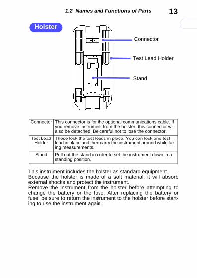
8This instrument includes the holster as standard equipment.Because the holster is made of a soft material, it will absorbexternal shocks and protect the instrument.Remove the instrument from the holster before attempting tochange the battery or the fuse. After replacing the battery orfuse, be sure to return the instrument to the holster before start-ing to use the instrument again.
Holster
Test Lead Holder
Connector
Stand
Connector This connector is for the optional communications cable. If you remove instrument from the holster, this connector will also be detached. Be careful not to lose the connector.
Test Lead Holder
These lock the test leads in place. You can lock one test lead in place and then carry the instrument around while tak-ing measurements.
Stand Pull out the stand in order to set the instrument down in a standing position.
1.2 Names and Functions of Parts
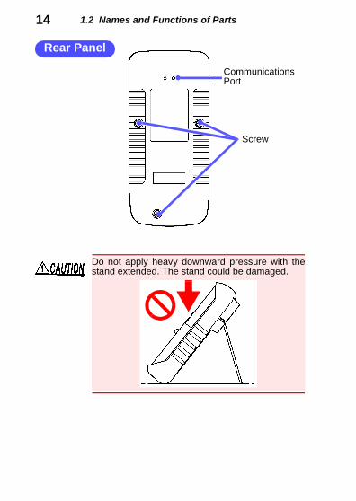
14Screw
Communications Port
Rear Panel
Do not apply heavy downward pressure with thestand extended. The stand could be damaged.
引
0
15
索
4
3
2
1
7
6
5
1
9
8
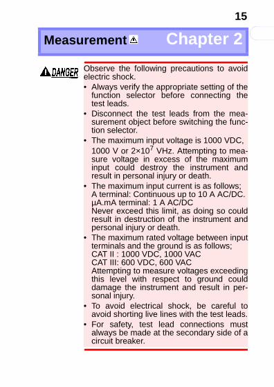
Measurement Chapter 2
Observe the following precautions to avoidelectric shock.• Always verify the appropriate setting of the
function selector before connecting thetest leads.
• Disconnect the test leads from the mea-surement object before switching the func-tion selector.
• The maximum input voltage is 1000 VDC, 1000 V or 2×10⁷ VHz. Attempting to mea-sure voltage in excess of the maximuminput could destroy the instrument andresult in personal injury or death.
• The maximum input current is as follows;A terminal: Continuous up to 10 A AC/DC.µA.mA terminal: 1 A AC/DCNever exceed this limit, as doing so couldresult in destruction of the instrument andpersonal injury or death.
• The maximum rated voltage between inputterminals and the ground is as follows;CAT II : 1000 VDC, 1000 VACCAT III: 600 VDC, 600 VACAttempting to measure voltages exceedingthis level with respect to ground coulddamage the instrument and result in per-sonal injury.
• To avoid electrical shock, be careful toavoid shorting live lines with the test leads.
• For safety, test lead connections mustalways be made at the secondary side of acircuit breaker.
2.1 Pre-Operation Inspection
16Operation CheckIf the operation check reveals any abnormalities,stop the check immediately and do not use theinstrument.
Required equipment:• Model 3804-50 (this instrument)• Model 3851-10 TEST LEAD• AC power receptacle
(100 V AC 50 Hz/60Hz commercial power supply)1. Set the function switch to "Ω".
2. Press the SHIFT key to conduct the continuity
check. ( lights.)❖ (23 page)
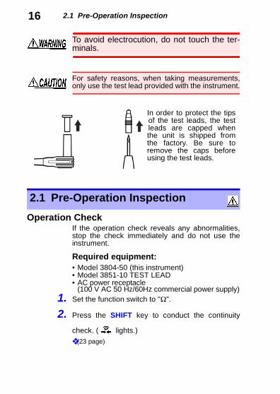
To avoid electrocution, do not touch the ter-minals.
For safety reasons, when taking measurements,only use the test lead provided with the instrument.
In order to protect the tipsof the test leads, the testleads are capped whenthe unit is shipped fromthe factory. Be sure toremove the caps beforeusing the test leads.
2.1 Pre-Operation Inspection
2.1 Pre-Operation Inspection
引
0
17
索
4
3
2
1
7
6
5
1
9
8
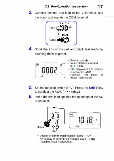
3. Connect the red test lead to the V terminal, and
the black test lead to the COM terminal.
4. Short the tips of the red and black test leads by
touching them together.
5. Set the function switch to "V". Press the SHIFT keyto conduct the ACV. ( lights.)
6. Insert the test lead tips into the openings of the ACreceptacle.
Black
Red
• Buzzer sounds.• Value stabilizes around
0 Ω.→ OK• OL displayed/ The display
is unstable →NO• Possible test leads or
tester malfunction.
• Display of commercial voltage levels → OK• No display of commercial voltage levels → NO
Possible tester malfunction.
BlackRed
2.1 Pre-Operation Inspection18
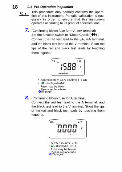
7. (Confirming blown fuse for mA, mA terminal)Set the function switch to "Diode Check ( )".Connect the red test lead to the µA, mA terminal,and the black test lead to the V terminal. Short thetips of the red and black test leads by touchingthem together.
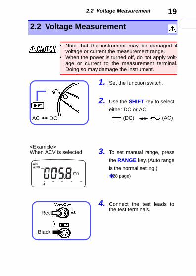
8. (Confirming blown fuse for A terminal)Connect the red test lead to the A terminal, andthe black test lead to the V terminal. Short the tipsof the red and black test leads by touching themtogether.
This procedure only partially confirms the opera-tion of this instrument. Periodic calibration is nec-essary in order to ensure that this instrumentoperates according to its product specifications.
• Approximately 1.6 V displayed→ OK• OL displayed→NO
Fuse may be blown.Please replace fuse.
❖ (53 page)
• Buzzer sounds→ OK• OL displayed→NO
Fuse may be blown. Please replace fuse.
❖ (53 page)
2.2 Voltage Measurement
引
0
19
索
4
3
2
1
7
6
5
1
9
8
2.2 Voltage Measurement
• Note that the instrument may be damaged ifvoltage or current the measurement range.
• When the power is turned off, do not apply volt-age or current to the measurement terminal.Doing so may damage the instrument.
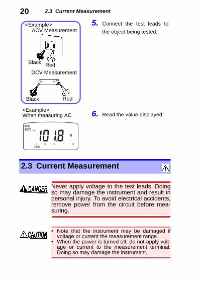
1. Set the function switch.
2. Use the SHIFT key to select
either DC or AC.
3. To set manual range, press
the RANGE key. (Auto range
is the normal setting.)❖(28 page)
4. Connect the test leads tothe test terminals.
(DC) (AC)
<Example>When ACV is selected
AC DC
Red
Black
2.3 Current Measurement
205. Connect the test leads tothe object being tested.
6. Read the value displayed.
ACV Measurement<Example>
DCV Measurement
<Example>When measuring AC
Black Red
Black Red
2.3 Current Measurement
Never apply voltage to the test leads. Doingso may damage the instrument and result inpersonal injury. To avoid electrical accidents,remove power from the circuit before mea-suring.
• Note that the instrument may be damaged ifvoltage or current the measurement range.
• When the power is turned off, do not apply volt-age or current to the measurement terminal.Doing so may damage the instrument.
2.3 Current Measurement
引
0
21
索
4
3
2
1
7
6
5
1
9
8
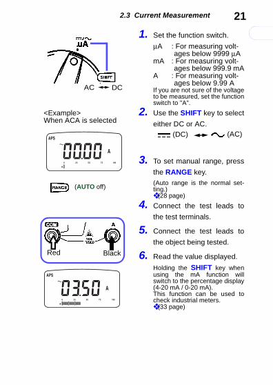
1. Set the function switch.
μA : For measuring volt-ages below 9999 μA
mA : For measuring volt-ages below 999.9 mA
A : For measuring volt-ages below 9.99 A
If you are not sure of the voltageto be measured, set the functionswitch to "A".
2. Use the SHIFT key to select
either DC or AC.
3. To set manual range, press
the RANGE key.(Auto range is the normal set-ting.)❖ (28 page)
4. Connect the test leads to
the test terminals.
5. Connect the test leads to
the object being tested.
6. Read the value displayed.
Holding the SHIFT key whenusing the mA function willswitch to the percentage display(4-20 mA / 0-20 mA).This function can be used tocheck industrial meters.❖ (33 page)
(DC) (AC)
<Example>When ACA is selected
(AUTO off)
AC DC
BlackRed
2.4 Resistance Measurement
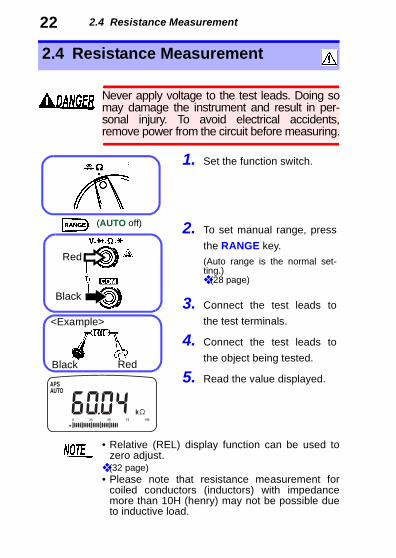
222.4 Resistance Measurement
Never apply voltage to the test leads. Doing somay damage the instrument and result in per-sonal injury. To avoid electrical accidents,remove power from the circuit before measuring.
1. Set the function switch.
2. To set manual range, press
the RANGE key.(Auto range is the normal set-ting.)❖ (28 page)
3. Connect the test leads to
the test terminals.
4. Connect the test leads to
the object being tested.
5. Read the value displayed.
<Example>
Black Red
Red
Black
(AUTO off)
• Relative (REL) display function can be used tozero adjust.
❖ (32 page)• Please note that resistance measurement for
coiled conductors (inductors) with impedancemore than 10H (henry) may not be possible dueto inductive load.
2.5 Continuity Check
引
0
23
索
4
3
2
1
7
6
5
1
9
8
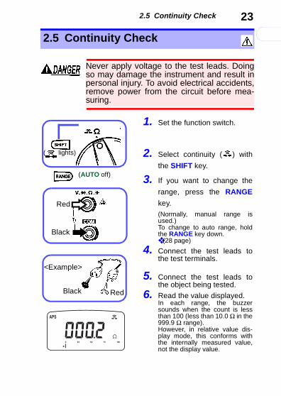
2.5 Continuity Check
Never apply voltage to the test leads. Doingso may damage the instrument and result inpersonal injury. To avoid electrical accidents,remove power from the circuit before mea-suring.
1. Set the function switch.
2. Select continuity ( ) with
the SHIFT key.
3. If you want to change the
range, press the RANGE
key.(Normally, manual range isused.)To change to auto range, holdthe RANGE key down.❖ (28 page)
4. Connect the test leads tothe test terminals.
5. Connect the test leads tothe object being tested.
6. Read the value displayed.In each range, the buzzersounds when the count is lessthan 100 (less than 10.0 Ω in the999.9 Ω range).However, in relative value dis-play mode, this conforms withthe internally measured value,not the display value.
<Example>
(AUTO off)
Black Red
Red
Black
( lights)
2.6 Diode Check
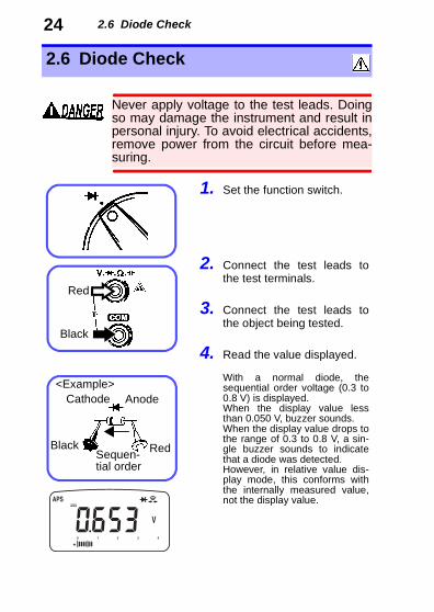
242.6 Diode Check
Never apply voltage to the test leads. Doingso may damage the instrument and result inpersonal injury. To avoid electrical accidents,remove power from the circuit before mea-suring.
1. Set the function switch.
2. Connect the test leads tothe test terminals.
3. Connect the test leads tothe object being tested.
4. Read the value displayed.
With a normal diode, thesequential order voltage (0.3 to0.8 V) is displayed.When the display value lessthan 0.050 V, buzzer sounds.When the display value drops tothe range of 0.3 to 0.8 V, a sin-gle buzzer sounds to indicatethat a diode was detected. However, in relative value dis-play mode, this conforms withthe internally measured value,not the display value.
<Example>
RedBlack
Cathode Anode
Sequen-tial order
Red
Black
2.7 Capacitance Measurement
引
0
25
索
4
3
2
1
7
6
5
1
9
8
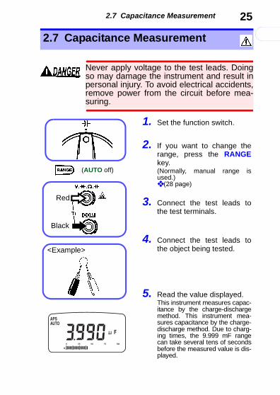
2.7 Capacitance Measurement
Never apply voltage to the test leads. Doingso may damage the instrument and result inpersonal injury. To avoid electrical accidents,remove power from the circuit before mea-suring.
1. Set the function switch.
2. If you want to change therange, press the RANGEkey.(Normally, manual range isused.)❖ (28 page)
3. Connect the test leads tothe test terminals.
4. Connect the test leads tothe object being tested.
5. Read the value displayed.This instrument measures capac-itance by the charge-dischargemethod. This instrument mea-sures capacitance by the charge-discharge method. Due to charg-ing times, the 9.999 mF rangecan take several tens of secondsbefore the measured value is dis-played.
(AUTO off)
<Example>
Red
Black
2.7 Capacitance Measurement
26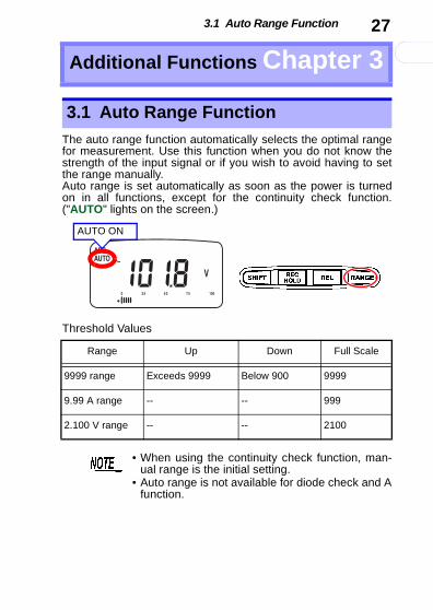
3.1 Auto Range Function
引
0
27
索
4
3
2
1
7
6
5
1
9
8
The auto range function automatically selects the optimal rangefor measurement. Use this function when you do not know thestrength of the input signal or if you wish to avoid having to setthe range manually.Auto range is set automatically as soon as the power is turnedon in all functions, except for the continuity check function.("AUTO" lights on the screen.)
Threshold Values
Additional Functions Chapter 3
3.1 Auto Range Function
AUTO ON
Range Up Down Full Scale
9999 range Exceeds 9999 Below 900 9999
9.99 A range -- -- 999
2.100 V range -- -- 2100
• When using the continuity check function, man-ual range is the initial setting.
• Auto range is not available for diode check and Afunction.
3.2 Manual Range Function
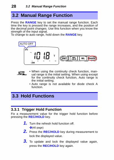
28Press the RANGE key to set the manual range function. Eachtime the key is pressed the range increases, and the position ofthe decimal point changes. Use this function when you know thestrength of the input signal.To change to auto range, hold down the RANGE key.
3.3.1 Trigger Hold FunctionFix a measurement value for the trigger hold function beforepressing the REC/HOLD key.
1. Turn the refresh hold function off.❖ (40 page)
2. Press the REC/HOLD key during measurement tolock the displayed value.
3. To update and lock the displayed value again,press the REC/HOLD key again.
3.2 Manual Range Function
• When using the continuity check function, man-ual range is the initial setting. When using exceptfor the continuity check function, Auto range isthe initial setting.
• Auto range is not available for diode check Afunction.
AUTO OFF
3.3 Hold Functions
3.3 Hold Functions
引
0
29
索
4
3
2
1
7
6
5
1
9
8
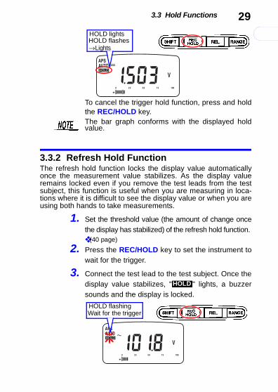
To cancel the trigger hold function, press and holdthe REC/HOLD key.
3.3.2 Refresh Hold FunctionThe refresh hold function locks the display value automaticallyonce the measurement value stabilizes. As the display valueremains locked even if you remove the test leads from the testsubject, this function is useful when you are measuring in loca-tions where it is difficult to see the display value or when you areusing both hands to take measurements.
1. Set the threshold value (the amount of change oncethe display has stabilized) of the refresh hold function. ❖ (40 page)
2. Press the REC/HOLD key to set the instrument towait for the trigger.
3. Connect the test lead to the test subject. Once thedisplay value stabilizes, " " lights, a buzzersounds and the display is locked.
HOLD lightsHOLD flashes→Lights
The bar graph conforms with the displayed holdvalue.
HOLD
HOLD flashingWait for the trigger
3.4 Recording Function
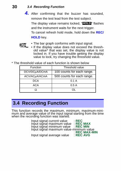
304. After confirming that the buzzer has sounded,remove the test lead from the test subject.
The display value remains locked, " " flashesand the instrument waits for the next trigger. To cancel refresh hold mode, hold down the REC/
HOLD key.
* The threshold value of each function is shown below
This function records the maximum, minimum, maximum-mini-mum and average value of the input signal starting from the timewhen the recording function was started.
Input signal current value : REC Input signal maximum value : REC MAXInput signal minimum value : REC MINInput signal maximum value-minimum value
: REC MAX-MINInput signal average value : REC AVG
HOLD
• The bar graph conforms with input signal.• If the display value does not exceed the thresh-
old value* that was set, the display value is notlocked in. If you have trouble getting the displayvalue to lock, try changing the threshold value.
Function Threshold value
DCV/DCμA/DCmA 100 counts for each range.ACV/ACμA/ACmA 500 counts for each range.
DCA 0.1 A
ACA 0.5 A
Ω OL
3.4 Recording Function
3.4 Recording Function
引
0
31
索
4
3
2
1
7
6
5
1
9
8
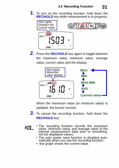
1. To turn on the recording function, hold down theREC/HOLD key while measurement is in progress.
2. Press the REC/HOLD key again to toggle betweenthe maximum value, minimum value, averagevalue, current value and the display.
When the maximum value (or minimum value) isupdated, the buzzer sounds.
3. To cancel the recording function, hold down theREC/HOLD key.
REC lightsDisplays the current value.
MAX-MIN
MIN
MAX
AVG
MAX lightsMaximum value display
Current value
• The recording function records the maximumvalue, minimum value, and average value of theinternal measurement data prior to smoothing,not the displayed values.
• The auto power save function is disabled auto-matically when you use the recording function.
• Bar graph shows the current value.
3.5 Relative (REL) Display Function
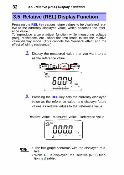
32Pressing the REL key causes future values to be displayed rela-tive to the currently displayed value, which becomes the refer-ence value.To reproduce a zero adjust function while measuring voltage(mV), resistance, etc., short the test leads to set the relativevalue display mode. (This cancels the Seebeck effect and theeffect of wiring resistance.)
1. Display the measured value that you want to setas the reference value.
2. Pressing the REL key sets the currently displayedvalue as the reference value, and displays futurevalues as relative values to that reference value.
3.5 Relative (REL) Display Function
Relative Value - Measured Value - Reference Value
• The bar graph conforms with the displayed rela-tive.
• While OL is displayed, the Relative (REL) func-tion is disabled.
3.6 4-20 mA (0-20 mA) Percentage Display Function
引
0
33
索
4
3
2
1
7
6
5
1
9
8
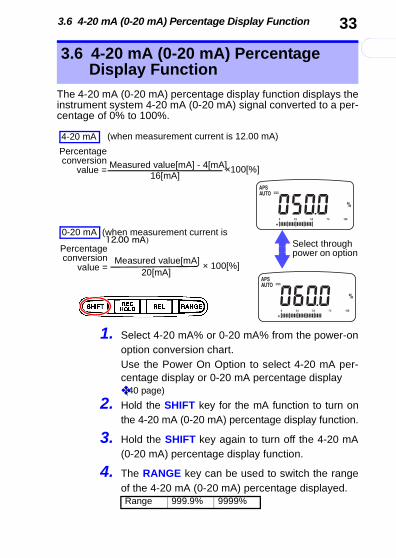
The 4-20 mA (0-20 mA) percentage display function displays theinstrument system 4-20 mA (0-20 mA) signal converted to a per-centage of 0% to 100%.
1. Select 4-20 mA% or 0-20 mA% from the power-onoption conversion chart.Use the Power On Option to select 4-20 mA per-centage display or 0-20 mA percentage display ❖(40 page)
2. Hold the SHIFT key for the mA function to turn onthe 4-20 mA (0-20 mA) percentage display function.
3. Hold the SHIFT key again to turn off the 4-20 mA(0-20 mA) percentage display function.
4. The RANGE key can be used to switch the rangeof the 4-20 mA (0-20 mA) percentage displayed.
3.6 4-20 mA (0-20 mA) Percentage Display Function
4-20 mA
0-20 mA (when measurement current is
Percentageconversion
value = Measured value[mA] - 4[mA]16[mA]
×100[%]
Select through power on option
Measured value[mA]20[mA]
× 100[%]
Percentageconversion
value =
(when measurement current is 12.00 mA)
12.00 mA)
Range 999.9% 9999%
3.7 Bar Graph Display Function
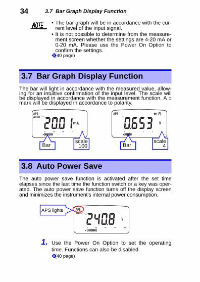
34The bar will light in accordance with the measured value, allow-ing for an intuitive confirmation of the input level. The scale willbe displayed in accordance with the measurement function. A ±mark will be displayed in accordance to polarity.
The auto power save function is activated after the set timeelapses since the last time the function switch or a key was oper-ated. The auto power save function turns off the display screenand minimizes the instrument's internal power consumption.
1. Use the Power On Option to set the operatingtime. Functions can also be disabled.❖ (40 page)
• The bar graph will be in accordance with the cur-rent level of the input signal.
• It is not possible to determine from the measure-ment screen whether the settings are 4-20 mA or0-20 mA. Please use the Power On Option toconfirm the settings.
❖ (40 page)
3.7 Bar Graph Display Function
Barscale
100 Barscale
4
3.8 Auto Power Save
APS lights
3.9 Overload Warning
引
0
35
索
4
3
2
1
7
6
5
1
9
8
2. To restore the auto power save function either turnthe rotary switch to the OFF position once or pressany key.
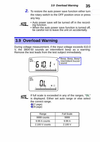
During voltage measurement, if the input voltage exceeds 610.0V, the 3804-50 sounds an intermittent beep as a warning.Remove the test leads from the test subject immediately.
• Auto power save will be turned off in the record-ing function.
• When the auto power save function is turned off,be careful not to leave the unit on accidentally.
3.9 Overload Warning
"Beep, Beep, Beep"Intermittent buzzersound
If full scale is exceeded in any of the ranges, "OL"is displayed. Either set auto range or else selectthe correct range.❖ (27 page) ❖ (28 page)
Range Full Scale
9999 counts 9999
9.99 A counts 9.99 A
2.100 V counts 2.100 V
3.10 Battery Depletion Alert Function
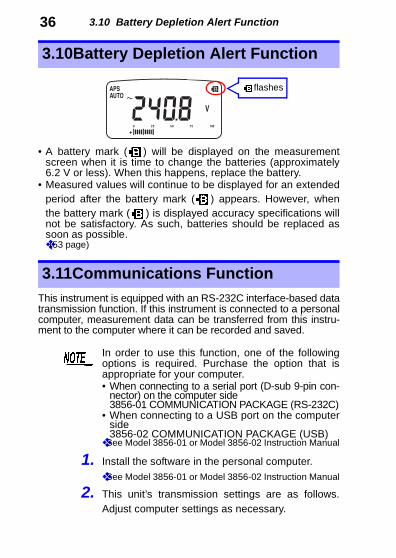
36• A battery mark ( ) will be displayed on the measurementscreen when it is time to change the batteries (approximately6.2 V or less). When this happens, replace the battery.
• Measured values will continue to be displayed for an extendedperiod after the battery mark ( ) appears. However, whenthe battery mark ( ) is displayed accuracy specifications willnot be satisfactory. As such, batteries should be replaced assoon as possible.❖(53 page)
This instrument is equipped with an RS-232C interface-based datatransmission function. If this instrument is connected to a personalcomputer, measurement data can be transferred from this instru-ment to the computer where it can be recorded and saved.
1. Install the software in the personal computer.❖See Model 3856-01 or Model 3856-02 Instruction Manual
2. This unit’s transmission settings are as follows.Adjust computer settings as necessary.
3.10Battery Depletion Alert Function
flashes
3.11Communications Function
In order to use this function, one of the followingoptions is required. Purchase the option that isappropriate for your computer.• When connecting to a serial port (D-sub 9-pin con-
nector) on the computer side3856-01 COMMUNICATION PACKAGE (RS-232C)
• When connecting to a USB port on the computerside3856-02 COMMUNICATION PACKAGE (USB)
❖See Model 3856-01 or Model 3856-02 Instruction Manual
3.11 Communications Function
引
0
37
索
4
3
2
1
7
6
5
1
9
8
3. If you are transmitting data using the included soft-ware, please set your unit’s power-on option as indi-cated below. (39 page)
4. When using the 3856-02 communications pack-age, install the driver in the personal computer.
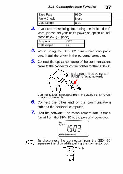
5. Connect the optical connector of the communicationscable to the connector on the holster for the 3804-50.
Communication is not possible if "RS-232C INTERFACE"is facing downwards.
6. Connect the other end of the communicationscable to the personal computer.
7. Start the software. The measurement data is trans-ferred from the 3804-50 to the personal computer.
Baud Rate 9600Parity Check None
Data Length 8 bit
Response OFFData output OFF
Make sure "RS-232C INTER-FACE" is facing upwards
To disconnect the connector from the 3804-50,squeeze the clips while pulling the connector out.
Clip

3.11 Communications Function
38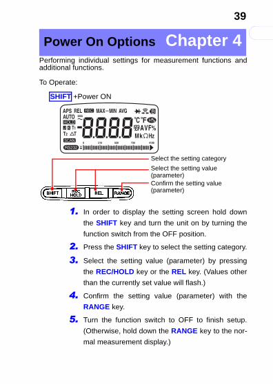
引
0
39
索
4
3
2
1
7
6
5
1
9
8
Performing individual settings for measurement functions andadditional functions.
To Operate:
1. In order to display the setting screen hold down
the SHIFT key and turn the unit on by turning the
function switch from the OFF position.
2. Press the SHIFT key to select the setting category.
3. Select the setting value (parameter) by pressing
the REC/HOLD key or the REL key. (Values other
than the currently set value will flash.)
4. Confirm the setting value (parameter) with the
RANGE key.
5. Turn the function switch to OFF to finish setup.
(Otherwise, hold down the RANGE key to the nor-
mal measurement display.)
Power On Options Chapter 4
SHIFT +Power ON
Select the setting category
Select the setting value (parameter)Confirm the setting value(parameter)
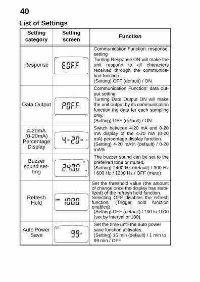
Setting category
Setting screen
Function
Response
Communication Function: response settingTurning Response ON will make theunit respond to all charactersreceived through the communica-tion function.(Setting) OFF (default) / ON
Data Output
Communication Function: data out-put settingTurning Data Output ON will makethe unit output by its communicationfunction the data for each samplingonly.(Setting) OFF (default) / ON
4-20mA(0-20mA)
Percentage Display
Switch between 4-20 mA and 0-20mA display of the 4-20 mA (0-20mA) percentage display function.(Setting) 4-20 mA% (default) / 0-20mA%
Buzzer sound set-
ting
The buzzer sound can be set to thepreferred tone or muted.(Setting) 2400 Hz (default) / 300 Hz/ 600 Hz / 1200 Hz / OFF (mute)
Refresh Hold
Set the threshold value (the amountof change once the display has stabi-lized) of the refresh hold function.Selecting OFF disables the refreshfunction. (Trigger hold functionenabled)(Setting) OFF (default) / 100 to 1000(set by interval of 100)
Auto Power Save
Set the time until the auto power save function activates.(Setting) 15 min (default) / 1 min to 99 min / OFF
引
0
41
索
4
3
2
1
7
6
5
1
9
8
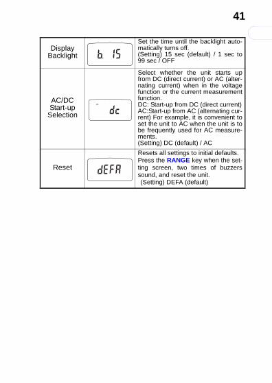
Display Backlight
Set the time until the backlight auto-matically turns off.(Setting) 15 sec (default) / 1 sec to99 sec / OFF
AC/DC Start-up
Selection
Select whether the unit starts upfrom DC (direct current) or AC (alter-nating current) when in the voltagefunction or the current measurementfunction.DC: Start-up from DC (direct current)AC:Start-up from AC (alternating cur-rent) For example, it is convenient toset the unit to AC when the unit is tobe frequently used for AC measure-ments.(Setting) DC (default) / AC
Reset
Resets all settings to initial defaults.Press the RANGE key when the set-ting screen, two times of buzzerssound, and reset the unit.(Setting) DEFA (default)
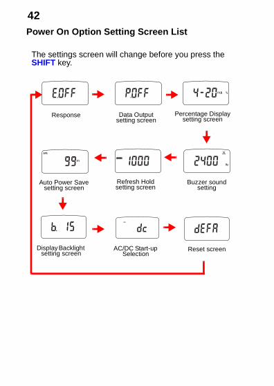
Response Data Outputsetting screen
Percentage Displaysetting screen
Buzzer sound setting
Refresh Holdsetting screen
Auto Power Savesetting screen
Display Backlight setting screen
AC/DC Start-up Selection
Reset screen
The settings screen will change before you press the SHIFT key.
5.1 General Specifications
引
0
43
索
4
3
2
1
7
6
5
1
9
8
Specifications Chapter 5
5.1 General Specifications
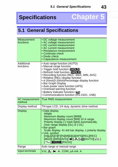
Measurementfunctions
• DC voltage measurement• AC voltage measurement• DC current measurement• AC current measurement• Resistance measurement• Continuity check• Diode check• Capacitance measurement
Additional functions
• Auto range function (AUTO)• Manual range function• Trigger hold function ( )• Refresh hold function ( )• Recording function (REC: MAX, MIN, AVG)• Relative (REL) display function• 4-20mA(0-20mA)Percentage display function• Bar Graph Display• Auto power save function (APS)• Overload warning function• Battery indicator function ( ) • Communications function (RS-232C, USB)
AC measurement method
True RMS measurement
Display method TN-type LCD, 1/4 duty, dynamic drive method
Display • Data display4digitsMaximum display count [9999] Maximum display count [999] 10 A rangePolarity display [-] mark lights automatically.Over range display [OL] or [-OL]
• Bar graphScale display, 41-dot bar display, ± polarity display
• Unit, symbol [m][μ][A][V][F][%][M][k][Ω][APS][REL][REC][MAX][-][MIN][AVG][ ][ ][ ][AUTO][ ][ ][ ][RS232]
Range Auto range or manual range
Input terminals V.Ω. . . , COM, μA.mA, A
HOLDHOLD
HOLD
5.1 General Specifications
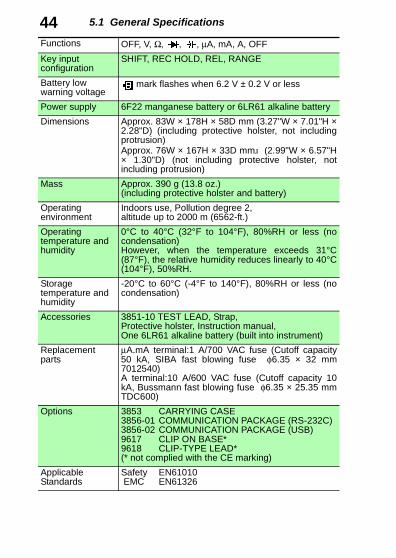
44Functions OFF, V, Ω, , , μA, mA, A, OFFKey input configuration
SHIFT, REC HOLD, REL, RANGE
Battery low warning voltage
mark flashes when 6.2 V ± 0.2 V or less
Power supply 6F22 manganese battery or 6LR61 alkaline battery
Dimensions Approx. 83W × 178H × 58D mm (3.27"W × 7.01"H ×2.28"D) (including protective holster, not includingprotrusion)Approx. 76W × 167H × 33D mm (2.99"W × 6.57"H× 1.30"D) (not including protective holster, notincluding protrusion)
Mass Approx. 390 g (13.8 oz.) (including protective holster and battery)
Operating environment
Indoors use, Pollution degree 2, altitude up to 2000 m (6562-ft.)
Operating temperature and humidity
0°C to 40°C (32°F to 104°F), 80%RH or less (nocondensation)However, when the temperature exceeds 31°C(87°F), the relative humidity reduces linearly to 40°C(104°F), 50%RH.
Storage temperature and humidity
-20°C to 60°C (-4°F to 140°F), 80%RH or less (nocondensation)
Accessories 3851-10 TEST LEAD, Strap, Protective holster, Instruction manual, One 6LR61 alkaline battery (built into instrument)
Replacementparts
μA.mA terminal:1 A/700 VAC fuse (Cutoff capacity50 kA, SIBA fast blowing fuse φ6.35 × 32 mm7012540)A terminal:10 A/600 VAC fuse (Cutoff capacity 10kA, Bussmann fast blowing fuse φ6.35 × 25.35 mmTDC600)
Options 3853 CARRYING CASE3856-01 COMMUNICATION PACKAGE (RS-232C)3856-02 COMMUNICATION PACKAGE (USB)9617 CLIP ON BASE*9618 CLIP-TYPE LEAD*(* not complied with the CE marking)
Applicable Standards
Safety EN61010 EMC EN61326

5.2 Electrical specifications
引
0
45
索
4
3
2
1
7
6
5
1
9
8
5.2 Electrical specifications
Noise resistanceNMRR
DCV: 60 dB or more (50 Hz/ 60 Hz)
Noise resistanceCMRR
DCV: 120 dB or more (DC/ 50 Hz/ 60 Hz, 1 kΩ unbalance)ACV: 60 dB or more(DC/ 50 Hz/ 60 Hz, 1 kΩ unbalance)
Response time (auto range)
DCV: within 1.2 s(0 V → 200 V auto range operation)ACV: within 2.2 s(0 V → 200 V auto range operation)Ω : within 2.0 s (Infinite → 0 Ω auto range operation)within 10.0 s(0 Ω → 50 MΩ auto range operation)
Dielectric strength 5.312 kV AC for 15 sec, sin wave, between input terminals and case (50 Hz/ 60 Hz)
Maximum input voltage
V terminal:1000 V DC/ 1000 Vrms or 2×10⁷ VHzMeasurement category CAT II 1000 V, CAT III 600 V(anticipated transient overvoltage 6000 V)
Maximum input current
A terminal:10 A AC/DC, μA.mA terminal:1000 mA AC/DC
Maximum rated voltage to earth
CAT II:1000 V DC/ 1000 VrmsCAT III:600 V DC/ 600 Vrms
Rated supply voltage
9.0 V DC
Maximum rated power
70 mVA (Max.), supply voltage: 9.0 V DC
Power duringAPS
0.2 mVA (Max.), supply voltage: 9.0 V
Continuous operating time
Approx. 30 hours (DCV measurement, when themanganese battery is used)Approx. 60 hours (DCV measurement, when thealkaline battery is used)
5.3 Accuracy
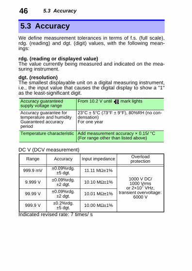
46We define measurement tolerances in terms of f.s. (full scale),rdg. (reading) and dgt. (digit) values, with the following mean-ings:
rdg. (reading or displayed value)The value currently being measured and indicated on the mea-suring instrument.
dgt. (resolution)The smallest displayable unit on a digital measuring instrument,i.e., the input value that causes the digital display to show a "1"as the least-significant digit.
DC V (DCV measurement)
Indicated revised rate: 7 times/ s
5.3 Accuracy
Accuracy guaranteed supply voltage range
From 10.2 V until mark lights
Accuracy guarantee for temperature and humidityGuaranteed accuracy period
23°C ± 5°C (73°F ± 9°F), 80%RH (no con-densation)For one year
Temperature characteristic Add measurement accuracy × 0.15/ °C (For range other than listed above)
Range Accuracy Input impedance Overload protection
999.9 mV ±0.09%rdg. ±5 dgt. 11.11 MΩ±1%
1000 V DC/ 1000 Vrms
or 2×10⁷ VHz, transient overvoltage:
6000 V
9.999 V ±0.09%rdg. ±2 dgt. 10.10 MΩ±1%
99.99 V ±0.09%rdg. ±2 dgt. 10.01 MΩ±1%
999.9 V ±0.2%rdg. ±5 dgt. 10.00 MΩ±1%
5.3 Accuracy
引
0
47
索
4
3
2
1
7
6
5
1
9
8
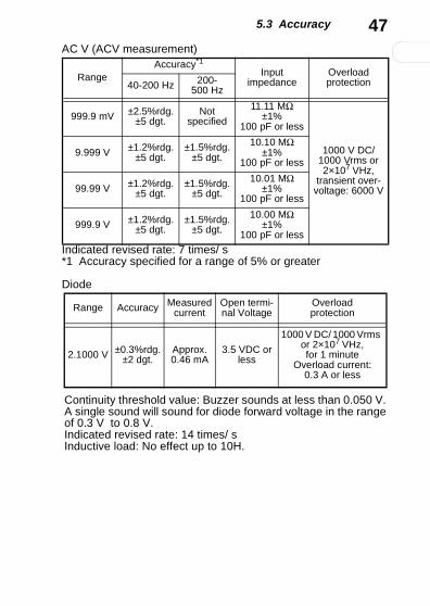
AC V (ACV measurement)
Indicated revised rate: 7 times/ s*1 Accuracy specified for a range of 5% or greater
Diode
RangeAccuracy*1
Input impedance
Overload protection40-200 Hz 200-
500 Hz
999.9 mV ±2.5%rdg. ±5 dgt.
Not specified
11.11 MΩ±1%
100 pF or less
1000 V DC/ 1000 Vrms or 2×10⁷ VHz,
transient over-voltage: 6000 V
9.999 V ±1.2%rdg. ±5 dgt.
±1.5%rdg. ±5 dgt.
10.10 MΩ±1%
100 pF or less
99.99 V ±1.2%rdg. ±5 dgt.
±1.5%rdg. ±5 dgt.
10.01 MΩ±1%
100 pF or less
999.9 V ±1.2%rdg. ±5 dgt.
±1.5%rdg. ±5 dgt.
10.00 MΩ±1%
100 pF or less
Range Accuracy Measured current
Open termi-nal Voltage
Overload protection
2.1000 V ±0.3%rdg. ±2 dgt.
Approx. 0.46 mA
3.5 VDC or less
1000 V DC/ 1000 Vrms or 2×10⁷ VHz, for 1 minute
Overload current: 0.3 A or less
Continuity threshold value: Buzzer sounds at less than 0.050 V. A single sound will sound for diode forward voltage in the range of 0.3 V to 0.8 V.Indicated revised rate: 14 times/ sInductive load: No effect up to 10H.
5.3 Accuracy
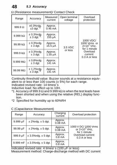
48Ω (Resistance measurement)/ Contact CheckC (Capacitance Measurement)
Indicated revised rate: 4 times/ s (100 μF or less)Measurement method: Charge-discharge method with DC current
Range Accuracy Measured current
Open terminal voltage
Overload protection
999.9 Ω ±0.3%rdg.±3 dgt.*1
Approx. 0.46 mA
3.5 VDC or less
1000 VDC/ 1000 Vrms or
2×10⁷ VHz, for 1 minute
Overload current:
0.3 A or less
9.999 kΩ ± 0.3%rdg. ± 3 dgt.*1
Approx. 155 μA
99.99 kΩ ± 0.3%rdg.± 3 dgt.
Approx. 15.5 μA
999.9 kΩ ± 0.3%rdg.± 3 dgt.
Approx. 1.55 μA
9.999 MΩ ± 0.8%rdg. ± 3 dgt.
Approx. 141 nA
99.99 MΩ ± 1.2%rdg. ± 3 dgt.*2
Approx. 141 nA
Continuity threshold value: Buzzer sounds at a resistance equiv-alent to or less than 100 counts (± 5%) for each range.Indicated revised rate: 14 times/ sInductive load: No effect up to 10H.*1 Accuracy of 999.9 Ω and 9.999 kΩ is when the test leads have
been shorted and when using the relative (REL) display func-tion.
*2 Specified for humidity up to 60%RH
Range Accuracy Charging current Overload protection
9.999 μF ± 2%rdg. ± 5 dgt. Approx. 0.08 mA
1000 V DC/ 1000 Vrms or 2×10⁷ VHz, for 1 minute
Overload current: 0.3 A or less
99.99 μF ± 2%rdg. ± 5 dgt. Approx. 0.08 mA
999.9 μF ± 3.5%rdg. ± 5 dgt. Approx. 0.8 mA
9.999 mF ± 3.5%rdg. ± 5 dgt. Approx. 0.8 mA
5.3 Accuracy
引
0
49
索
4
3
2
1
7
6
5
1
9
8
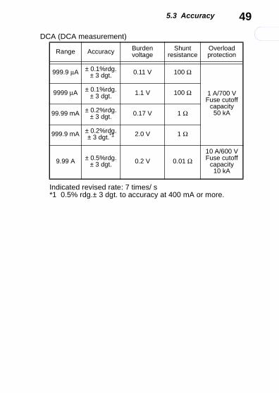
DCA (DCA measurement)
Range Accuracy Burden voltage
Shunt resistance
Overload protection
999.9 μA ± 0.1%rdg.± 3 dgt. 0.11 V 100 Ω
1 A/700 VFuse cutoff
capacity 50 kA
9999 μA ± 0.1%rdg.± 3 dgt. 1.1 V 100 Ω
99.99 mA ± 0.2%rdg.± 3 dgt. 0.17 V 1 Ω
999.9 mA ± 0.2%rdg.± 3 dgt.*1 2.0 V 1 Ω
9.99 A ± 0.5%rdg.± 3 dgt. 0.2 V 0.01 Ω
10 A/600 VFuse cutoff
capacity10 kA
Indicated revised rate: 7 times/ s*1 0.5% rdg.± 3 dgt. to accuracy at 400 mA or more.
5.3 Accuracy
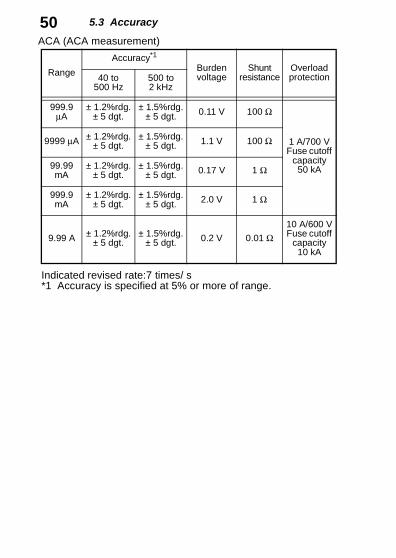
50ACA (ACA measurement)Range
Accuracy*1
Burden voltage
Shunt resistance
Overload protection40 to
500 Hz500 to2 kHz
999.9 μA
± 1.2%rdg.± 5 dgt.
± 1.5%rdg.± 5 dgt. 0.11 V 100 Ω
1 A/700 VFuse cutoff
capacity 50 kA
9999 μA ± 1.2%rdg.± 5 dgt.
± 1.5%rdg.± 5 dgt. 1.1 V 100 Ω
99.99 mA
± 1.2%rdg.± 5 dgt.
± 1.5%rdg.± 5 dgt. 0.17 V 1 Ω
999.9 mA
± 1.2%rdg.± 5 dgt.
± 1.5%rdg.± 5 dgt. 2.0 V 1 Ω
9.99 A ± 1.2%rdg.± 5 dgt.
± 1.5%rdg.± 5 dgt. 0.2 V 0.01 Ω
10 A/600 VFuse cutoff
capacity 10 kA
Indicated revised rate:7 times/ s*1 Accuracy is specified at 5% or more of range.
6.1 Troubleshooting
引
0
51
索
4
3
2
1
7
6
5
1
9
8
When this instrument has been in extended stor-age (for more than one year), the instrument willnot be able to meet its specifications. Be sure tohave the instrument calibrated before using it.
Maintenanceand Service Chapter 6
6.1 Troubleshooting
• If damage is suspected, check the "Trouble-shooting" section before contacting your dealeror Hioki representative.
• Calibration and repair of this instrument shouldbe performed only under the supervision ofqualified technicians knowledgeable about thedangers involved.
• When transporting the instrument, pack theinstrument so that it will not sustain damage dur-ing shipping, and include a description of exist-ing damage. We cannot accept responsibility fordamage incurred during shipping.
• Never modify the instrument. Only Hioki serviceengineers should disassemble or repair theinstrument. Failure to observe these precautionsmay result in fire, electric shock, or injury.
• If the protective functions of the instrument aredamaged, either remove it from service or markit clearly so that others do not use it inadvert-ently.

6.1 Troubleshooting
52Before returning for repairIf problems are encountered with operation, check the appropri-ate items below.If the cause of the problem still cannot be found, try resetting thesystem. This returns most of the system settings to their factorydefaults.❖See (41 page)
Symptom Checks Ref Page
Screen is blank
Is the battery dead?→ Replace the battery.
(53 page)
Are the battery wires damaged?→ Contact your nearest dealer.
Screen shuts off after a few moments
Is the battery dead?→ Replace the battery.
(53 page)
Is the auto power save function being activated?→ Check the auto power save setting.
(34 page)
A portion of the screen is blank
Is a portion of the display blank when the entire screen is supposed to be dis-played?→ Return for repair
(56 page)
Cannot mea-sure electric current
Is the fuse blown?Check to see if the fuse is blown.→ Replace the fuse.
(18 page)(53 page)
Are the test leads damaged?→ Perform a continuity check to check
the test leads. If the test leads are damaged, replace the test leads.
(23 page)
Communica-tion not possi-ble
Is there a problem with the communica-tion settings of the 3801-50 and the computer?Is the communication cable connected correctly?
(36 page)
6.2 Cleaning
引
0
53
索
4
3
2
1
7
6
5
1
9
8
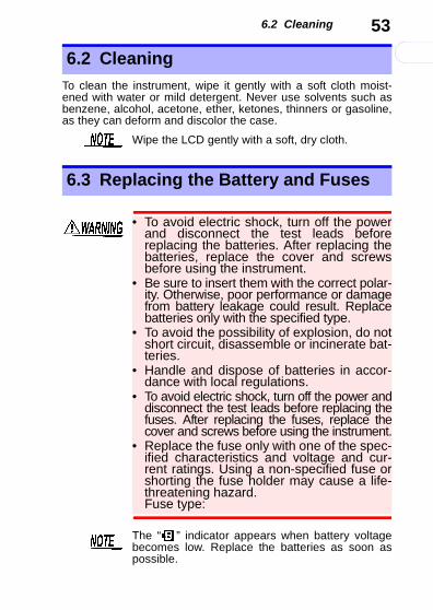
To clean the instrument, wipe it gently with a soft cloth moist-ened with water or mild detergent. Never use solvents such asbenzene, alcohol, acetone, ether, ketones, thinners or gasoline,as they can deform and discolor the case.
6.2 Cleaning
Wipe the LCD gently with a soft, dry cloth.
6.3 Replacing the Battery and Fuses
• To avoid electric shock, turn off the powerand disconnect the test leads beforereplacing the batteries. After replacing thebatteries, replace the cover and screwsbefore using the instrument.
• Be sure to insert them with the correct polar-ity. Otherwise, poor performance or damagefrom battery leakage could result. Replacebatteries only with the specified type.
• To avoid the possibility of explosion, do notshort circuit, disassemble or incinerate bat-teries.
• Handle and dispose of batteries in accor-dance with local regulations.
• To avoid electric shock, turn off the power anddisconnect the test leads before replacing thefuses. After replacing the fuses, replace thecover and screws before using the instrument.
• Replace the fuse only with one of the spec-ified characteristics and voltage and cur-rent ratings. Using a non-specified fuse orshorting the fuse holder may cause a life-threatening hazard.Fuse type:
The “ ” indicator appears when battery voltagebecomes low. Replace the batteries as soon aspossible.
6.3 Replacing the Battery and Fuses
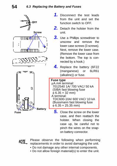
541. Disconnect the test leadsfrom the unit and set thefunction switch to OFF.
2. Detach the holster from theunit.
3. Use a Phillips screwdriver tounscrew and remove thelower case screws (3 screws).Next, remove the lower case.(Remove the lower case fromthe bottom. The top is con-nected by a hook.)
4. Replace the battery (6F22(manganese) or 6LR61(alkaline)) or fuse.
5. Close the screw on the lowercase, and then reattach theholster. When closing thecase up, be careful not topinch the wires on the snap-on battery connector.
Fuse typeμA.mA terminal:7012540 1A/ 700 VAC/ 50 kA(SIBA fast blowing fuse φ 6.35 × 32 mm)
A terminal:TDC600-10A/ 600 VAC/ 10 kA(Bussmann fast blowing fuse φ 6.35 × 25.35 mm)
Screw
BatteryFuse
Please observe the following when performingreplacements in order to avoid damaging the unit.• Do not damage any other internal components.• Do not allow foreign material(s) to enter the unit.
6.4 Checking the Instrument Software Version
引
0
55
索
4
3
2
1
7
6
5
1
9
8
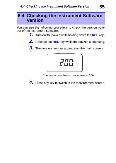
You can use the following procedure to check the version num-ber of the instrument software.
1. Turn on the power while holding down the REL key.
2. Release the REL key while the buzzer is sounding.
3. The version number appears on the main screen.
4. Press any key to switch to the measurement screen.
6.4 Checking the Instrument Software Version
The version number on this screen is 2.00.
6.5 Displaying All On-Screen Items
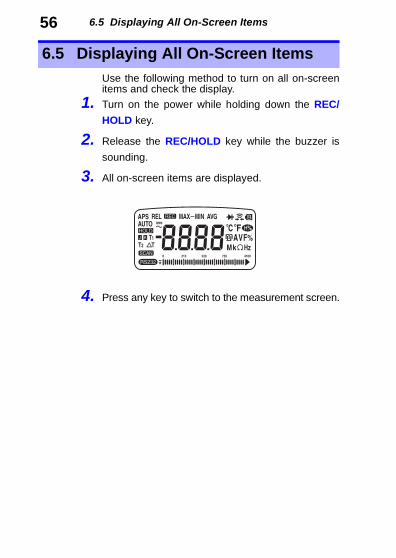
56Use the following method to turn on all on-screenitems and check the display.
1. Turn on the power while holding down the REC/
HOLD key.
2. Release the REC/HOLD key while the buzzer is
sounding.
3. All on-screen items are displayed.
4. Press any key to switch to the measurement screen.
6.5 Displaying All On-Screen Items
引
0
索
4
3
2
1
7
6
5
1
9
8


HIOKI 3804-50 DIGITAL Hi TESTERInstruction Manual
Publication date: April 2008 Revised edition 1
Edited and published by HIOKI E.E. CORPORATIONTechnical Support Section
All inquiries to International Sales and Marketing De-partment81 Koizumi, Ueda, Nagano, 386-1192, JapanTEL: +81-268-28-0562 / FAX: +81-268-28-0568 E-mail: [email protected] http://www.hioki.com/
Printed in Japan 3804C980-01
• All reasonable care has been taken in the productionof this manual, but if you find any points which areunclear or in error, please contact your supplier or theInternational Sales and Marketing Department atHIOKI headquarters.
• In the interests of product development, the contentsof this manual are subject to revision without priornotice.
• The content of this manual is protected by copyright.No reproduction, duplication or modification of thecontent is permitted without the authorization of HiokiE.E. Corporation.

Printed on recycled paper
3804C980-01 08-04H
HEAD OFFICE81 Koizumi, Ueda, Nagano 386-1192, JapanTEL +81-268-28-0562 / FAX +81-268-28-0568E-mail: [email protected] http://www.hioki.com/HIOKI USA CORPORATION6 Corporate Drive, Cranbury, NJ 08512, USATEL +1-609-409-9109 / FAX +1-609-409-9108

取扱説明書
3804-50
ディジタルハイテスタDIGITAL HiTESTER
1.形名、品名、図版など(赤色箇所)を変更2.微妙なずれはドキュテックで行うので変更しない。
3.モノクロで送付する。
※お問い合わせは、最寄りの営業所または本社販売企画課まで。3804C980-01 08-04H
この取扱説明書は再生紙を使用しています。
INSTRUCTION MANUAL