Embed Size (px)
Citation preview
ECOROLL / CINEROLL
Manuale d’istruzione User manual
Manuel d’instruction BetriebsanleitungManual de usuario
Attenzione
Articolo soggetto a modifiche senza preavvisoSubject to alteration without noticeModifications techniques sous réserveTechnische Änderungen vorbehaltenReservamos el derecho a realizar modificationes
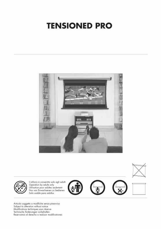
TENSIONED PRO
L’utilizzo è consentito solo agli adultiOperation by adults onlyUtilisation pour adultes seulementNur von Enwachsenen zu bedienenSolo usable para adultos
ECOROLL / CINEROLL
Eventuali modifiche saranno relizzate senza darne preavviso
10.06.20
09
Manuale d’istruzione User manual
Manuel d’instruction BetriebsanleitungManual de usuario
Attenzione
Ligra S.r.l. - Visual Communication SuppliesVia Artigiani 29/31 - 29020 Vigolzone (PC) - ItalyTel: +39-0523.872014 Fax: +39-0523.870089
E-mail: [email protected] Web: www.ligra.it
!
Please open the carton and check accessories according to the list.Adust the position between the two plates:
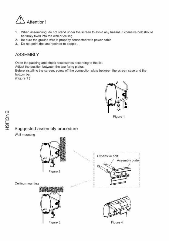
1.W hen assembling, do not stand in right under the screen to avoid any hazard. Expansive boltshould be firmly punched and fixed into the wall or ceiling.
2.Be sure the ground wire is connected with power cable e�ectively to avoid electric shock3.W hen use the laser pointer function on remote control, please be sure not to point to peopledirectly to avoid any hurt.
Before installing screen, please screw off the connection plate between casing and bottom bar(Figure 1 )
Figure 1
1
Figure 2
Figure 3 Figure 4
Wall mounting
Expansive boltAssemble plate
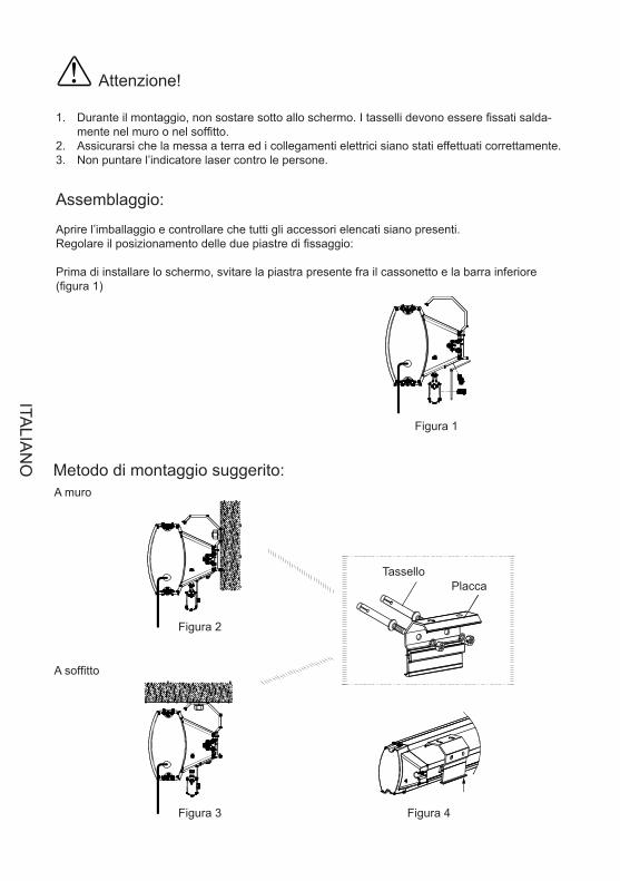
Attenzione!
Durante il montaggio, non sostare sotto allo schermo. I tasselli devono essere fissati salda-1. mente nel muro o nel soffitto.Assicurarsi che la messa a terra ed i collegamenti elettrici siano stati effettuati correttamente.2. Non puntare l’indicatore laser contro le persone.3.
Assemblaggio:
Aprire l’imballaggio e controllare che tutti gli accessori elencati siano presenti.Regolare il posizionamento delle due piastre di fissaggio:
Prima di installare lo schermo, svitare la piastra presente fra il cassonetto e la barra inferiore (figura 1)
Figura 1
Figura 2
Figura 3 Figura 4
TasselloPlacca
Metodo di montaggio suggerito:A muro
A soffitto
ITALIA
NO
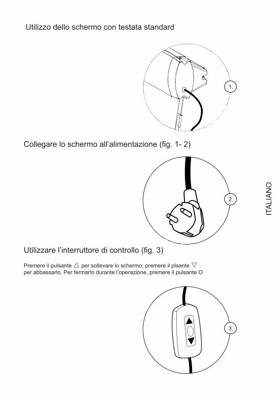
Utilizzo dello schermo con testata standard
Collegare lo schermo all’alimentazione (fig. 1- 2)
Utilizzare l’interruttore di controllo (fig. 3)
Premere il pulsante r per sollevare lo schermo; premere il plsante s per abbassarlo. Per fermarlo durante l’operazione, premere il pulsante O
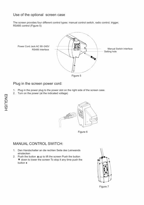
The screen provide four control ways: ;cordless trigger control; manual switch contr l; RS485 contr l (Figure 5)
RF remote controlo o
1.
The screen provide four control ways: ;cordless trigger control; manual switch contr l; RS485 contr l (Figure 5)
RF remote controlo o
2.
The screen provide four control ways: ;cordless trigger control; manual switch contr l; RS485 contr l (Figure 5)
RF remote controlo o
3.
ITA
LIA
NO
1.Plug the power cord into the power jack on the right end cap .2.Switch on the power (within stated voltage)
1.Insert manual switch cord into the interface of right end cap
Push the button down, lift the screenPush the button up to down the screenTo stop any time while the screen is in motion,turn the button to o" "
2.Connect power on
The screen provide four control ways: ;cordless trigger control; manual switch contr l; RS485 contr l (Figure 5)
RF remote controlo o
Power Cord Jack AC 90~240VManual Switch InterfaceRS485 Interface
Learn Code Hole
Figure 5
2
Figure 6
Figure 7
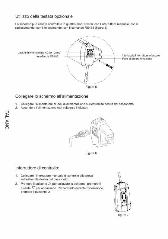
Utilizzo della testata opzionale
Lo schermo può essere controllato in quattro modi diversi: con l’interruttore manuale, con il radiocomando, con il telecomando, con il comando RS485 (figura 5)
Collegare lo schermo all’alimentazione:
Collegare l’alimentatore al jack di alimentazione sull’estremità destra del cassonetto1. Accendere l’alimentazione (col voltaggio indicato)2.
Figura 5
Figura 6
Jack di alimentazione AC90 - 240VInterfaccia RS485 Interfaccia interruttore manuale
Foro di programmazione
Interruttore di controllo:
Collegare l’interruttore manuale di controllo alla presa 1. sull’estremità destra del cassonettoPremere il pulsante 2. r per sollevare lo schermo; premere il plsante s per abbassarlo. Per fermarlo durante l’operazione, premere il pulsante O
ITALIA
NO
1.The remote has been set up at the factory, and should work right away. However, if you would liketo control another screen with the same control, you will need to use the learn function.
2.Make sure the manual switch is in the closed position and the switch- cord disconnected. Please pressthe hole at the right-end-cap for 3 seconds, indicated by a light flash, then press the back of remotecontrol the receiver led light at the right-end-cap will become normally on from flash situation. Now wefinish the learn code function . Please refer to remote control user manul for some details instructionabout learn code function
The remote uses a powerful anti-interference module, providing excellent stability. By using the screensbuilt-in-receiver, the screen can be controlled from as far away as 40 meters (wall will reduce the distance)
3.Please operate as follows
3
Figure 8
Figure 9
UpStopDownLaser pointer button
Remote control(Battery AAA DC 1.5V 2)
Figura 8
Figura 9
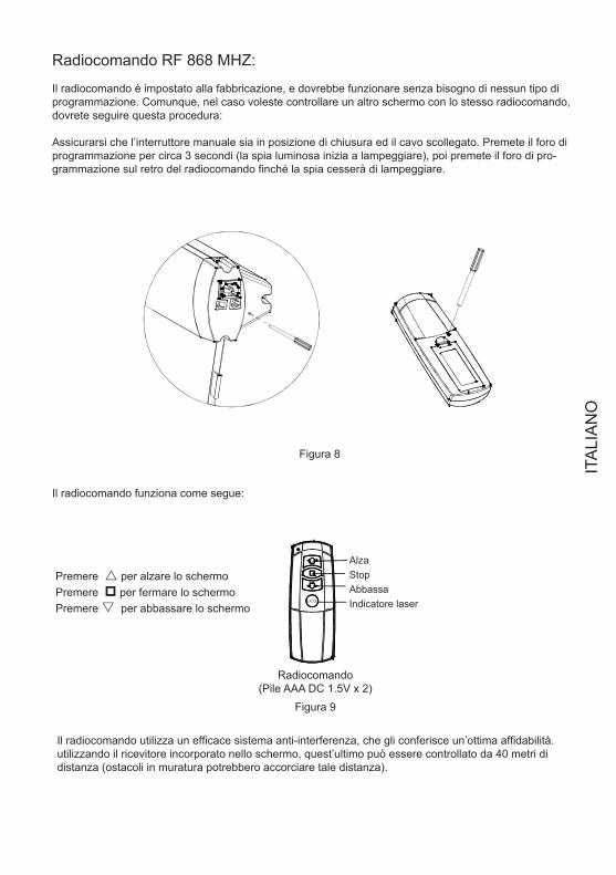
Radiocomando RF 868 MHZ:
Il radiocomando è impostato alla fabbricazione, e dovrebbe funzionare senza bisogno di nessun tipo di programmazione. Comunque, nel caso voleste controllare un altro schermo con lo stesso radiocomando, dovrete seguire questa procedura:
Assicurarsi che l’interruttore manuale sia in posizione di chiusura ed il cavo scollegato. Premete il foro di programmazione per circa 3 secondi (la spia luminosa inizia a lampeggiare), poi premete il foro di pro-grammazione sul retro del radiocomando finché la spia cesserà di lampeggiare.
Il radiocomando funziona come segue:
AlzaStopAbbassaIndicatore laser
Premere r per alzare lo schermoPremere p per fermare lo schermoPremere s per abbassare lo schermo
Radiocomando(Pile AAA DC 1.5V x 2)
Il radiocomando utilizza un efficace sistema anti-interferenza, che gli conferisce un’ottima affidabilità. utilizzando il ricevitore incorporato nello schermo, quest’ultimo può essere controllato da 40 metri di distanza (ostacoli in muratura potrebbero accorciare tale distanza).
ITA
LIA
NO
1.2.Insert the trigger directly into trigger out interface of projector,
when running the projector, the screen will down automaticallywhen closing the projector , the screen will up automatically
Make sure the manual switch is in the closed position and the switch- cord disconnected
1. Also make sureyour projector open trigger function. press the hole of right end cap 3 seconds with small touchneedle, indicated by a light flash, then press the hole in the back of cordless trigger 3 seconds, receiver
led light at the right-end-cap will become normally on from flash situation.. Now we finish the learn codefunction.
Make sure the manual switch is in the closed position and the switch- cord disconnected
Please refer to cordless trigger control user manul for some details instruction about learn codefunction.
Plug one side of the signal cord into the computer output interface at right side of the s endcap, the other side of the signal cord to plug into the interface of computer Rs485, and then you
can run the screen up/pause/down via computer.
creen's
The remote has been set up at the factory, and should work right away. Please operate as follows:
If need control another screen with the same trigger, or changed new remote control than need finish learncode again as follows.
After finishing learn code function, now, you can insert projector trigger out interface straightly. Ourpatented cordless trigger allows your screen synchronize its up and down with projector power cycle.When projector power open, the screen up ,projector power close, the screen down automatically. Orwhen projector power is open situation, you insert wireless trigger, the screen will up, take the triggeroff projector, the screen will also down automatically.
4
Figure 10
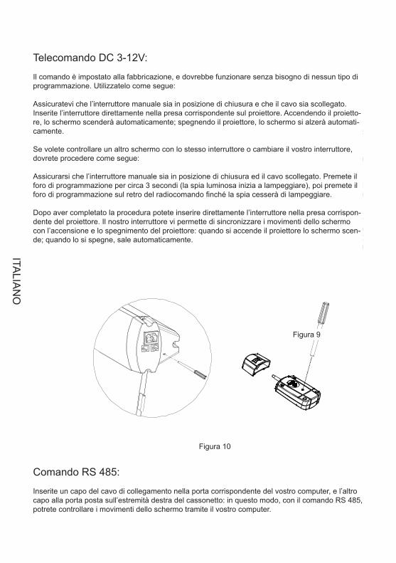
Telecomando DC 3-12V:
Il comando è impostato alla fabbricazione, e dovrebbe funzionare senza bisogno di nessun tipo di programmazione. Utilizzatelo come segue:
Assicuratevi che l’interruttore manuale sia in posizione di chiusura e che il cavo sia scollegato.Inserite l’interruttore direttamente nella presa corrispondente sul proiettore. Accendendo il proietto-re, lo schermo scenderà automaticamente; spegnendo il proiettore, lo schermo si alzerà automati-camente.
Se volete controllare un altro schermo con lo stesso interruttore o cambiare il vostro interruttore, dovrete procedere come segue:
Assicurarsi che l’interruttore manuale sia in posizione di chiusura ed il cavo scollegato. Premete il foro di programmazione per circa 3 secondi (la spia luminosa inizia a lampeggiare), poi premete il foro di programmazione sul retro del radiocomando finché la spia cesserà di lampeggiare.
Dopo aver completato la procedura potete inserire direttamente l’interruttore nella presa corrispon-dente del proiettore. Il nostro interruttore vi permette di sincronizzare i movimenti dello schermo con l’accensione e lo spegnimento del proiettore: quando si accende il proiettore lo schermo scen-de; quando lo si spegne, sale automaticamente.
Figura 10
Figura 9
Comando RS 485:
Inserite un capo del cavo di collegamento nella porta corrispondente del vostro computer, e l’altro capo alla porta posta sull’estremità destra del cassonetto: in questo modo, con il comando RS 485, potrete controllare i movimenti dello schermo tramite il vostro computer.
ITALIA
NO
Fabric is always on the right position before out of factory. However, If fabric needs adjusting, a microadjusting switch is provided. Please use a screw knife of 3mm diameter or other enclosed tool to insertinto the hole the right bottom of case for adjusting
1. Adjusting for up limited position (fabric drawing back stage)When the fabric in the stage of drawingback and the bottom shaft is not in right place, please operate as the up limited position drawing, turnas direction, the fabric will descend; turn as direction, the fabric will rise .+" " " -"
Note: please insert the tool as the showed angle.
2.Adjusting for bottom limited position (fabric completely open up) when the fabric completelyopen up, while the top black border is not in right place .please operate as the bottom limitedposition drawing ,turn as direction, the fabric will descend; turn as direction, the
fabric will rise .+" " " -"
5
Figure 11
Figure 12
Adjusting tool
Front side
Up limited adjusting
Bottom limitedadjusting
Figura 11
Figura 12
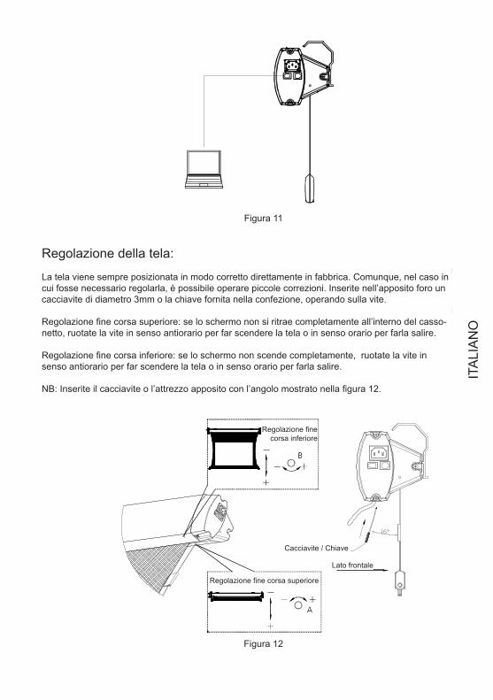
Regolazione della tela:
La tela viene sempre posizionata in modo corretto direttamente in fabbrica. Comunque, nel caso in cui fosse necessario regolarla, è possibile operare piccole correzioni. Inserite nell’apposito foro un cacciavite di diametro 3mm o la chiave fornita nella confezione, operando sulla vite.
Regolazione fine corsa superiore: se lo schermo non si ritrae completamente all’interno del casso-netto, ruotate la vite in senso antiorario per far scendere la tela o in senso orario per farla salire.
Regolazione fine corsa inferiore: se lo schermo non scende completamente, ruotate la vite in senso antiorario per far scendere la tela o in senso orario per farla salire.
NB: Inserite il cacciavite o l’attrezzo apposito con l’angolo mostrato nella figura 12.
Regolazione fine corsa inferiore
Regolazione fine corsa superiore
Cacciavite / Chiave
Lato frontale
ITA
LIA
NO

If the tension is loose or over-tension, please adjust is as following fig
Tighten
Tool
Insert
Loose
(If the are any other malfunction, please consult your local approval agent)
Light dusting is possiblewith a feather duster
Area
Casing
Surface Clean with a feather duster
Dusty Dirty
Clean with a mild soap solution and dry witha lint free cloth.Take care not to scratch the casing
Use a lint brush to remove any dirt
Phenomenon *Check parts reason Processing method
*Check if the battery power off
*Capacitor broke up
*Motor broke up
*A little rolling reversal
Remote control malfunction
Abnormal sound of motor
Motor not run
Fabric rolling reversal
Replace battery
Change capacitor
Change motor
Adjust according to thechapter of adjusting" "
Figure 13
6
Regolazione del tensionamento:
Se il tensionamento è eccessivo o insufficiente, regolatelo come segue:
Figura 13
InserireStringere
Allentare Chiave
Manutenzione:
Malfunzionamenti:
Se si verificassero altri malfunzionamenti consultate il vostro rivenditore.
Malfunzionamento Controllo da effettuare SoluzioneIl radiocomando non
funzionaVerificare la carica della
pilaSostituire la pila
Il motore è rumoroso Il condensatore è guasto Sostituire il condensa-tore
Il motore non funziona Il motore è guasto Sostituire il motoreLa tela non si riavvolge
correttamenteVerificare il fine corsa
della telaRegolare il fine corsa
della tela come indicato
Area Polvere SporcoCassonetto Usare un comune piumino Pulire con una soluzione di
sapone delicato ed un panno di cotone. Non graffiare la superficie
Schermo Usare un comune piumino Usare un panno di cotone
ITALIA
NO
1.Please do not run the screen continuously above 5minutes to avoid the motor damaged due tooverheat aging; when next operation please wait the motor cool down
2.Do not scratch or fold up the fabric.3.Afer usage, please check again there are no other foreign objectives on the screen surface and
then draw back the fabric into the case
Screen learn needle
Trigger learn needle
Cordless rigger
Remote control
Quantity
LASE R
PictureName
Hex key
Adjusting tool
Assembling plate
Expansive bolt
1
1
1
1
1
1
2
4
7
Power cord 2m(standard)5m(optional)
RS485 cord 5m
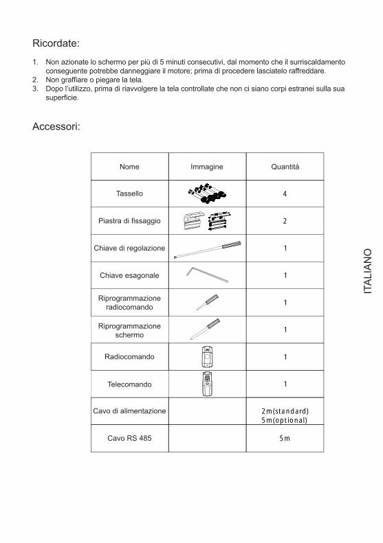
Ricordate:
Non azionate lo schermo per più di 5 minuti consecutivi, dal momento che il surriscaldamento 1. conseguente potrebbe danneggiare il motore; prima di procedere lasciatelo raffreddare.Non graffiare o piegare la tela.2. Dopo l’utilizzo, prima di riavvolgere la tela controllate che non ci siano corpi estranei sulla sua 3. superficie.
Accessori:
Nome
Tassello
Piastra di fissaggio
Chiave di regolazione
Chiave esagonale
Radiocomando
Telecomando
Cavo di alimentazione
Cavo RS 485
Riprogrammazione radiocomando
Riprogrammazione schermo
Immagine Quantità
If the tension is loose or over-tension, please adjust is as following fig
Tighten
Tool
Insert
Loose
(If the are any other malfunction, please consult your local approval agent)
Light dusting is possiblewith a feather duster
Area
Casing
Surface Clean with a feather duster
Dusty Dirty
Clean with a mild soap solution and dry witha lint free cloth.Take care not to scratch the casing
Use a lint brush to remove any dirt
Phenomenon *Check parts reason Processing method
*Check if the battery power off
*Capacitor broke up
*Motor broke up
*A little rolling reversal
Remote control malfunction
Abnormal sound of motor
Motor not run
Fabric rolling reversal
Replace battery
Change capacitor
Change motor
Adjust according to thechapter of adjusting" "
Figure 13
6
ITA
LIA
NO
!
Please open the carton and check accessories according to the list.Adust the position between the two plates:
1.W hen assembling, do not stand in right under the screen to avoid any hazard. Expansive boltshould be firmly punched and fixed into the wall or ceiling.
2.Be sure the ground wire is connected with power cable e�ectively to avoid electric shock3.W hen use the laser pointer function on remote control, please be sure not to point to peopledirectly to avoid any hurt.
Before installing screen, please screw off the connection plate between casing and bottom bar(Figure 1 )
Figure 1
1
Figure 2
Figure 3 Figure 4
Wall mounting
Expansive boltAssemble plate
Attention!
When assembling, do not stand under the screen to avoid any hazard. Expansive bolt should 1. be firmly fixed into the wall or ceiling.Be sure the ground wire is properly connected with power cable 2. Do not point the laser pointer to people .3.
ASSEMBLY
Open the packing and check accessories according to the list.Adjust the position between the two fixing plates:Before installing the screen, screw off the connection plate between the screen case and the bottom bar(Figure 1 )
Figure 1
Figure 2
Figure 3 Figure 4
Expansive boltAssembly plate
Suggested assembly procedureWall mounting
Ceiling mounting
EN
GLIS
H
Use of the standard screen case
Plug in the screen power cord (Figures 1-2)
Use of the MANUAL CONTROL SWITCH (Figure 3)
Push the button ▲up to lift the screen Push the button ▼ down to lower the screenTo stop it any time push the button ●
The screen provide four control ways: ;cordless trigger control; manual switch contr l; RS485 contr l (Figure 5)
RF remote controlo o
1.
The screen provide four control ways: ;cordless trigger control; manual switch contr l; RS485 contr l (Figure 5)
RF remote controlo o
2.
The screen provide four control ways: ;cordless trigger control; manual switch contr l; RS485 contr l (Figure 5)
RF remote controlo o
3.
EN
GLI
SH
1.Plug the power cord into the power jack on the right end cap .2.Switch on the power (within stated voltage)
1.Insert manual switch cord into the interface of right end cap
Push the button down, lift the screenPush the button up to down the screenTo stop any time while the screen is in motion,turn the button to o" "
2.Connect power on
The screen provide four control ways: ;cordless trigger control; manual switch contr l; RS485 contr l (Figure 5)
RF remote controlo o
Power Cord Jack AC 90~240VManual Switch InterfaceRS485 Interface
Learn Code Hole
Figure 5
2
Figure 6
Figure 7
Use of the optional screen case
The screen provides four different control types: manual control switch, radio control, trigger, RS485 control (Figure 5)
Plug in the screen power cord:
Plug in the power plug to the power slot on the right side of the screen case.1. Turn on the power (at the indicated voltage) 2.
Figure 5
Figure 6
Figure 7
Power Cord Jack AC 90~240V RS485 Interface Manual Switch Interface
Setting hole
MANUAL CONTROL SWITCH:
Den Handschalter an die rechten Seite des Leinwands 1. einsteckenPush the button ▲up to lift the screen Push the button 2. ▼ down to lower the screen To stop it any time push the button ●
EN
GLIS
H
1.The remote has been set up at the factory, and should work right away. However, if you would liketo control another screen with the same control, you will need to use the learn function.
2.Make sure the manual switch is in the closed position and the switch- cord disconnected. Please pressthe hole at the right-end-cap for 3 seconds, indicated by a light flash, then press the back of remotecontrol the receiver led light at the right-end-cap will become normally on from flash situation. Now wefinish the learn code function . Please refer to remote control user manul for some details instructionabout learn code function
The remote uses a powerful anti-interference module, providing excellent stability. By using the screensbuilt-in-receiver, the screen can be controlled from as far away as 40 meters (wall will reduce the distance)
3.Please operate as follows
3
Figure 8
Figure 9
UpStopDownLaser pointer button
Remote control(Battery AAA DC 1.5V 2)
Figure 8
Figure 9
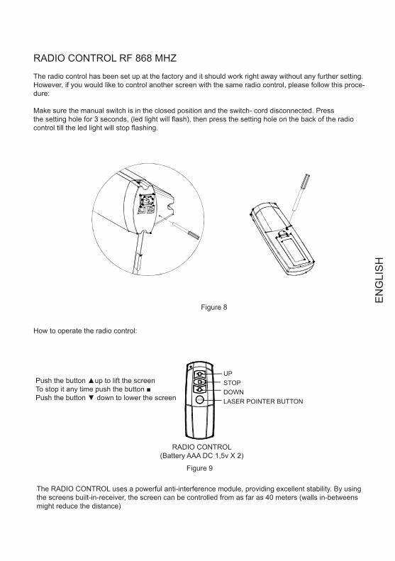
RADIO CONTROL RF 868 MHZ
The radio control has been set up at the factory and it should work right away without any further setting. However, if you would like to control another screen with the same radio control, please follow this proce-dure:
Make sure the manual switch is in the closed position and the switch- cord disconnected. Pressthe setting hole for 3 seconds, (led light will flash), then press the setting hole on the back of the radiocontrol till the led light will stop flashing.
How to operate the radio control:
UPSTOP DOWN LASER POINTER BUTTON
Push the button ▲up to lift the screen To stop it any time push the button ■ Push the button ▼ down to lower the screen
RADIO CONTROL (Battery AAA DC 1,5v X 2)
The RADIO CONTROL uses a powerful anti-interference module, providing excellent stability. By using the screens built-in-receiver, the screen can be controlled from as far as 40 meters (walls in-betweens might reduce the distance)
EN
GLI
SH
1.2.Insert the trigger directly into trigger out interface of projector,
when running the projector, the screen will down automaticallywhen closing the projector , the screen will up automatically
Make sure the manual switch is in the closed position and the switch- cord disconnected
1. Also make sureyour projector open trigger function. press the hole of right end cap 3 seconds with small touchneedle, indicated by a light flash, then press the hole in the back of cordless trigger 3 seconds, receiver
led light at the right-end-cap will become normally on from flash situation.. Now we finish the learn codefunction.
Make sure the manual switch is in the closed position and the switch- cord disconnected
Please refer to cordless trigger control user manul for some details instruction about learn codefunction.
Plug one side of the signal cord into the computer output interface at right side of the s endcap, the other side of the signal cord to plug into the interface of computer Rs485, and then you
can run the screen up/pause/down via computer.
creen's
The remote has been set up at the factory, and should work right away. Please operate as follows:
If need control another screen with the same trigger, or changed new remote control than need finish learncode again as follows.
After finishing learn code function, now, you can insert projector trigger out interface straightly. Ourpatented cordless trigger allows your screen synchronize its up and down with projector power cycle.When projector power open, the screen up ,projector power close, the screen down automatically. Orwhen projector power is open situation, you insert wireless trigger, the screen will up, take the triggeroff projector, the screen will also down automatically.
4
Figure 10
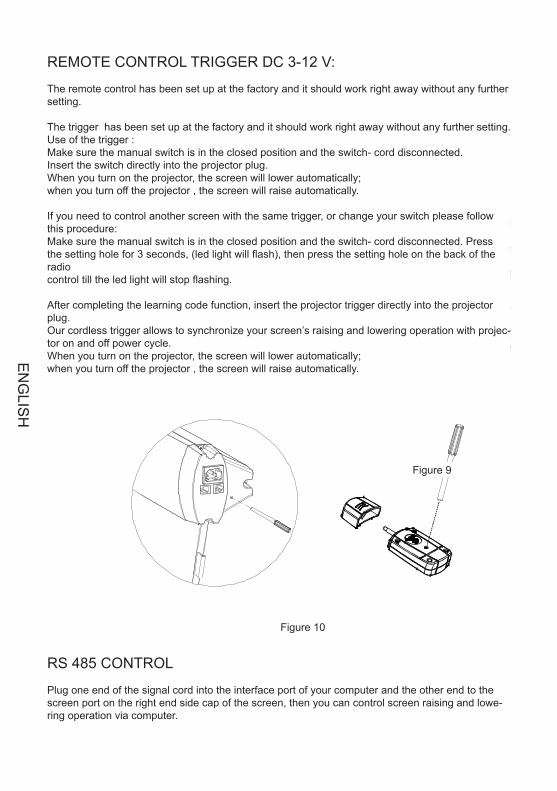
REMOTE CONTROL TRIGGER DC 3-12 V:
The remote control has been set up at the factory and it should work right away without any further setting.
The trigger has been set up at the factory and it should work right away without any further setting. Use of the trigger :Make sure the manual switch is in the closed position and the switch- cord disconnected.Insert the switch directly into the projector plug. When you turn on the projector, the screen will lower automatically;when you turn off the projector , the screen will raise automatically.
If you need to control another screen with the same trigger, or change your switch please follow this procedure:Make sure the manual switch is in the closed position and the switch- cord disconnected. Pressthe setting hole for 3 seconds, (led light will flash), then press the setting hole on the back of the radiocontrol till the led light will stop flashing.
After completing the learning code function, insert the projector trigger directly into the projector plug. Our cordless trigger allows to synchronize your screen’s raising and lowering operation with projec-tor on and off power cycle.When you turn on the projector, the screen will lower automatically;when you turn off the projector , the screen will raise automatically.
Figure 10
Figure 9
RS 485 CONTROL
Plug one end of the signal cord into the interface port of your computer and the other end to the screen port on the right end side cap of the screen, then you can control screen raising and lowe-ring operation via computer.
EN
GLIS
H
Fabric is always on the right position before out of factory. However, If fabric needs adjusting, a microadjusting switch is provided. Please use a screw knife of 3mm diameter or other enclosed tool to insertinto the hole the right bottom of case for adjusting
1. Adjusting for up limited position (fabric drawing back stage)When the fabric in the stage of drawingback and the bottom shaft is not in right place, please operate as the up limited position drawing, turnas direction, the fabric will descend; turn as direction, the fabric will rise .+" " " -"
Note: please insert the tool as the showed angle.
2.Adjusting for bottom limited position (fabric completely open up) when the fabric completelyopen up, while the top black border is not in right place .please operate as the bottom limitedposition drawing ,turn as direction, the fabric will descend; turn as direction, the
fabric will rise .+" " " -"
5
Figure 11
Figure 12
Adjusting tool
Front side
Up limited adjusting
Bottom limitedadjusting
Figure 11
Figure 12
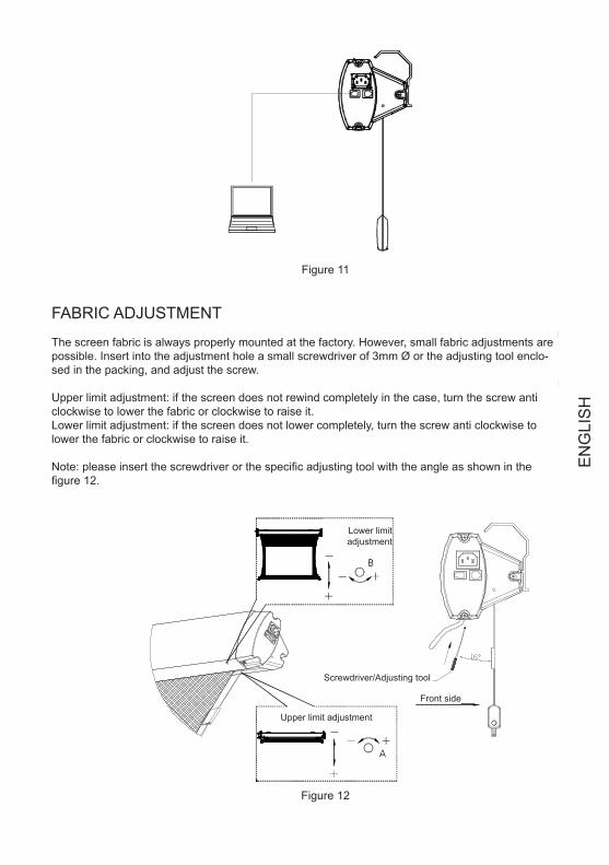
FABRIC ADJUSTMENT
The screen fabric is always properly mounted at the factory. However, small fabric adjustments are possible. Insert into the adjustment hole a small screwdriver of 3mm Ø or the adjusting tool enclo-sed in the packing, and adjust the screw.
Upper limit adjustment: if the screen does not rewind completely in the case, turn the screw anti clockwise to lower the fabric or clockwise to raise it.Lower limit adjustment: if the screen does not lower completely, turn the screw anti clockwise to lower the fabric or clockwise to raise it.
Note: please insert the screwdriver or the specific adjusting tool with the angle as shown in the figure 12.
Lower limit adjustment
Upper limit adjustment
Screwdriver/Adjusting tool
Front side
EN
GLI
SH
If the tension is loose or over-tension, please adjust is as following fig
Tighten
Tool
Insert
Loose
(If the are any other malfunction, please consult your local approval agent)
Light dusting is possiblewith a feather duster
Area
Casing
Surface Clean with a feather duster
Dusty Dirty
Clean with a mild soap solution and dry witha lint free cloth.Take care not to scratch the casing
Use a lint brush to remove any dirt
Phenomenon *Check parts reason Processing method
*Check if the battery power off
*Capacitor broke up
*Motor broke up
*A little rolling reversal
Remote control malfunction
Abnormal sound of motor
Motor not run
Fabric rolling reversal
Replace battery
Change capacitor
Change motor
Adjust according to thechapter of adjusting" "
Figure 13
6
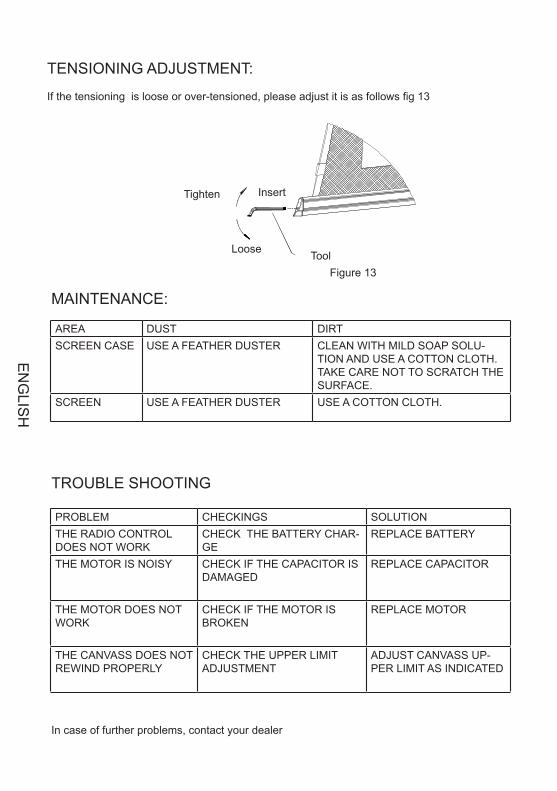
TENSIONING ADJUSTMENT:
If the tensioning is loose or over-tensioned, please adjust it is as follows fig 13
Figure 13
InsertTighten
Loose Tool
MAINTENANCE:
TROUBLE SHOOTING
In case of further problems, contact your dealer
PROBLEM CHECKINGS SOLUTIONTHE RADIO CONTROL DOES NOT WORK
CHECK THE BATTERY CHAR-GE
REPLACE BATTERY
THE MOTOR IS NOISY CHECK IF THE CAPACITOR IS DAMAGED
REPLACE CAPACITOR
THE MOTOR DOES NOT WORK
CHECK IF THE MOTOR IS BROKEN
REPLACE MOTOR
THE CANVASS DOES NOT REWIND PROPERLY
CHECK THE UPPER LIMIT ADJUSTMENT
ADJUST CANVASS UP-PER LIMIT AS INDICATED
AREA DUST DIRTSCREEN CASE USE A FEATHER DUSTER CLEAN WITH MILD SOAP SOLU-
TION AND USE A COTTON CLOTH. TAKE CARE NOT TO SCRATCH THE SURFACE.
SCREEN USE A FEATHER DUSTER USE A COTTON CLOTH.
EN
GLIS
H
If the tension is loose or over-tension, please adjust is as following fig
Tighten
Tool
Insert
Loose
(If the are any other malfunction, please consult your local approval agent)
Light dusting is possiblewith a feather duster
Area
Casing
Surface Clean with a feather duster
Dusty Dirty
Clean with a mild soap solution and dry witha lint free cloth.Take care not to scratch the casing
Use a lint brush to remove any dirt
Phenomenon *Check parts reason Processing method
*Check if the battery power off
*Capacitor broke up
*Motor broke up
*A little rolling reversal
Remote control malfunction
Abnormal sound of motor
Motor not run
Fabric rolling reversal
Replace battery
Change capacitor
Change motor
Adjust according to thechapter of adjusting" "
Figure 13
6
TENSIONING ADJUSTMENT:
If the tensioning is loose or over-tensioned, please adjust it is as follows fig 13
AREA DUST DIRTSCREEN CASE USE A FEATHER DUSTER CLEAN WITH MILD SOAP SOLU-
TION AND USE A COTTON CLOTH. TAKE CARE NOT TO SCRATCH THE SURFACE.
SCREEN USE A FEATHER DUSTER USE A COTTON CLOTH.
1.Please do not run the screen continuously above 5minutes to avoid the motor damaged due tooverheat aging; when next operation please wait the motor cool down
2.Do not scratch or fold up the fabric.3.Afer usage, please check again there are no other foreign objectives on the screen surface and
then draw back the fabric into the case
Screen learn needle
Trigger learn needle
Cordless rigger
Remote control
Quantity
LASE R
PictureName
Hex key
Adjusting tool
Assembling plate
Expansive bolt
1
1
1
1
1
1
2
4
7
Power cord 2m(standard)5m(optional)
RS485 cord 5m
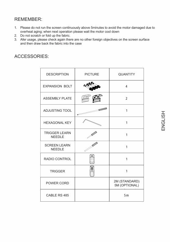
REMEMBER:
Please do not run the screen continuously above 5minutes to avoid the motor damaged due to 1. overheat aging; when next operation please wait the motor cool downDo not scratch or fold up the fabric.2. Afer usage, please check again there are no other foreign objectives on the screen surface 3. and then draw back the fabric into the case
ACCESSORIES:
DESCRIPTION
EXPANSION BOLT
ASSEMBLY PLATE
ADJUSTING TOOL
HEXAGONAL KEY
RADIO CONTROL
TRIGGER
POWER CORD 2M (STANDARD)5M (OPTIONAL)
TRIGGER LEARN NEEDLE
SCREEN LEARN NEEDLE
PICTURE QUANTITY
CABLE RS 485
EN
GLI
SH
!
Please open the carton and check accessories according to the list.Adust the position between the two plates:
1.W hen assembling, do not stand in right under the screen to avoid any hazard. Expansive boltshould be firmly punched and fixed into the wall or ceiling.
2.Be sure the ground wire is connected with power cable e�ectively to avoid electric shock3.W hen use the laser pointer function on remote control, please be sure not to point to peopledirectly to avoid any hurt.
Before installing screen, please screw off the connection plate between casing and bottom bar(Figure 1 )
Figure 1
1
Figure 2
Figure 3 Figure 4
Wall mounting
Expansive boltAssemble plate
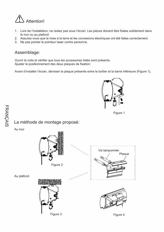
Attention!
Lors de l’installation, ne restez pas sous l’écran. Les pièces doivent être fixées solidement dans 1. le mur ou au plafond. Assurez-vous que la mise à la terre et les connexions électriques ont été faites correctement. 2. Ne pas pointer le pointeur laser contre personne.3.
Assemblage:
Ouvrir le colis et vérifier que tous les accessoires listés sont présents. Ajuster le positionnement des deux plaques de fixation:
Avant d’installer l’écran, dévisser la plaque présente entre le boîtier et la barre inférieure (Figure 1),
Figure 1
Figure 2
Figure 3 Figure 4
Vis tamponnéePlaque
La méthode de montage proposé: Au mur
Au plafond
FRA
NÇ
AIS
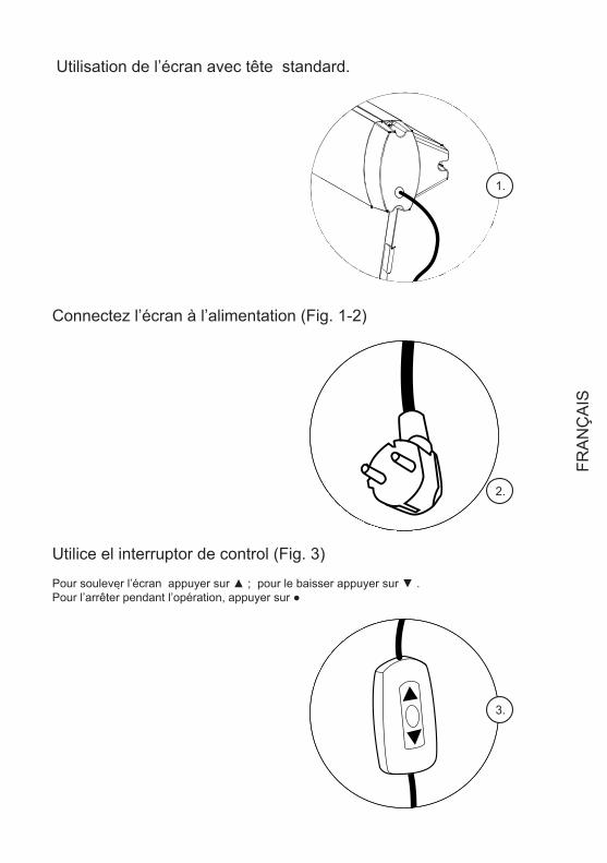
Utilisation de l’écran avec tête standard.
Connectez l’écran à l’alimentation (Fig. 1-2)
Utilice el interruptor de control (Fig. 3)
Pour soulever l’écran appuyer sur ▲ ; pour le baisser appuyer sur ▼ .Pour l’arrêter pendant l’opération, appuyer sur ●
The screen provide four control ways: ;cordless trigger control; manual switch contr l; RS485 contr l (Figure 5)
RF remote controlo o
1.
The screen provide four control ways: ;cordless trigger control; manual switch contr l; RS485 contr l (Figure 5)
RF remote controlo o
2.
The screen provide four control ways: ;cordless trigger control; manual switch contr l; RS485 contr l (Figure 5)
RF remote controlo o
3.
FRA
NÇ
AIS
1.Plug the power cord into the power jack on the right end cap .2.Switch on the power (within stated voltage)
1.Insert manual switch cord into the interface of right end cap
Push the button down, lift the screenPush the button up to down the screenTo stop any time while the screen is in motion,turn the button to o" "
2.Connect power on
The screen provide four control ways: ;cordless trigger control; manual switch contr l; RS485 contr l (Figure 5)
RF remote controlo o
Power Cord Jack AC 90~240VManual Switch InterfaceRS485 Interface
Learn Code Hole
Figure 5
2
Figure 6
Figure 7
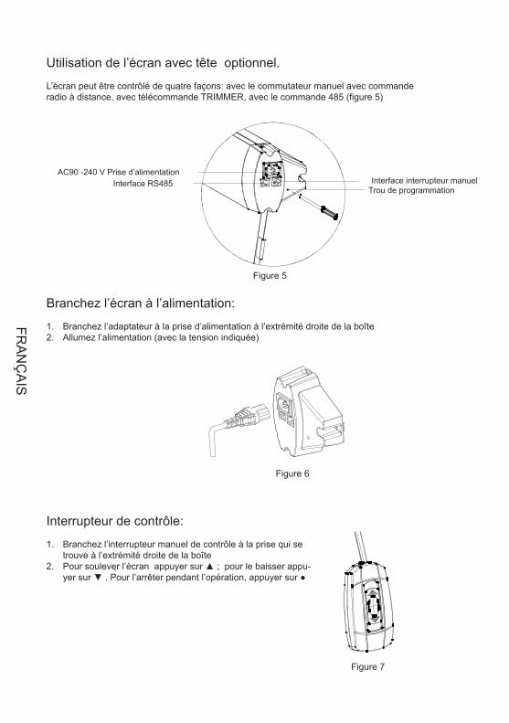
Utilisation de l’écran avec tête optionnel.
L’écran peut être contrôlé de quatre façons: avec le commutateur manuel avec commande radio à distance, avec télécommande TRIMMER, avec le commande 485 (figure 5)
Branchez l’écran à l’alimentation:
Branchez l’adaptateur à la prise d’alimentation à l’extrémité droite de la boîte 1. Allumez l’alimentation (avec la tension indiquée) 2.
Figure 5
Figure 6
Figure 7
AC90 -240 V Prise d’alimentation Interface RS485 Interface interrupteur manuel
Trou de programmation
Interrupteur de contrôle:
Branchez l’interrupteur manuel de contrôle à la prise qui se 1. trouve à l’extrémité droite de la boîte Pour soulever l’écran appuyer sur ▲ ; pour le baisser appu-2. yer sur ▼ . Pour l’arrêter pendant l’opération, appuyer sur ●
FRA
NÇ
AIS
1.The remote has been set up at the factory, and should work right away. However, if you would liketo control another screen with the same control, you will need to use the learn function.
2.Make sure the manual switch is in the closed position and the switch- cord disconnected. Please pressthe hole at the right-end-cap for 3 seconds, indicated by a light flash, then press the back of remotecontrol the receiver led light at the right-end-cap will become normally on from flash situation. Now wefinish the learn code function . Please refer to remote control user manul for some details instructionabout learn code function
The remote uses a powerful anti-interference module, providing excellent stability. By using the screensbuilt-in-receiver, the screen can be controlled from as far away as 40 meters (wall will reduce the distance)
3.Please operate as follows
3
Figure 8
Figure 9
UpStopDownLaser pointer button
Remote control(Battery AAA DC 1.5V 2)
Figure 8
Figure 9
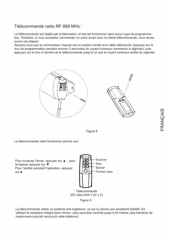
Télécommande radio RF 868 MHz :
La télécommande est réglée par la fabrication, et devrait fonctionner sans aucun type de programma-tion. Toutefois, si vous souhaitez commander un autre écran avec la même télécommande, vous devez suivre ces étapes: Assurez-vous que le commutateur manuel est en position arrêté et le câble débranché. Appuyez sur le trou de programmation pendant environ 3 secondes (le voyant lumineux commence à clignoter), puis appuyez sur le trou à l’arrière de la télécommande jusqu’à ce que le voyant lumineux arrête de clignoter
La télécommande radio fonctionne comme suit:
Soulever Stop Baisser Pointeur laser
Pour soulever l’écran appuyer sur ▲ ; pour le baisser appuyer sur ▼ .Pour l’arrêter pendant l’opération, appuyer sur ■
Télécommande (DC piles AAA 1.5V x 2)
La télécommande utilise un système anti-ingérence, ce qui lui donne une excellente fiabilité. En utilisant le récepteur intégré dans l’écran, celui peut être contrôlé jusqu’à 40 mètres (des barrières de maçonnerie pourrait raccourcir cette distance).
FRA
NÇ
AIS
1.2.Insert the trigger directly into trigger out interface of projector,
when running the projector, the screen will down automaticallywhen closing the projector , the screen will up automatically
Make sure the manual switch is in the closed position and the switch- cord disconnected
1. Also make sureyour projector open trigger function. press the hole of right end cap 3 seconds with small touchneedle, indicated by a light flash, then press the hole in the back of cordless trigger 3 seconds, receiver
led light at the right-end-cap will become normally on from flash situation.. Now we finish the learn codefunction.
Make sure the manual switch is in the closed position and the switch- cord disconnected
Please refer to cordless trigger control user manul for some details instruction about learn codefunction.
Plug one side of the signal cord into the computer output interface at right side of the s endcap, the other side of the signal cord to plug into the interface of computer Rs485, and then you
can run the screen up/pause/down via computer.
creen's
The remote has been set up at the factory, and should work right away. Please operate as follows:
If need control another screen with the same trigger, or changed new remote control than need finish learncode again as follows.
After finishing learn code function, now, you can insert projector trigger out interface straightly. Ourpatented cordless trigger allows your screen synchronize its up and down with projector power cycle.When projector power open, the screen up ,projector power close, the screen down automatically. Orwhen projector power is open situation, you insert wireless trigger, the screen will up, take the triggeroff projector, the screen will also down automatically.
4
Figure 10
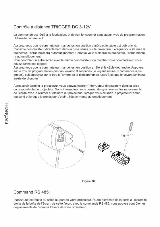
Contrôle à distance TRIGGER DC 3-12V:
La commande est réglé à la fabrication, et devrait fonctionner sans aucun type de programmation. Utilisez-le comme suit:
Assurez-vous que le commutateur manuel est en position d’arête et le câble est débranché. Placez le commutateur directement dans la prise située sur le projecteur. Lorsque vous allumez le projecteur, l’écran baissera automatiquement ; lorsque vous éteindrez le projecteur, l’écran monte-ra automatiquement. Pour contrôler un autre écran avec le même commutateur ou modifier votre commutateur, vous devez suivre ces étapes: Assurez-vous que le commutateur manuel est en position arrêté et le câble débranché. Appuyez sur le trou de programmation pendant environ 3 secondes (le voyant lumineux commence à cli-gnoter), puis appuyez sur le trou à l’arrière de la télécommande jusqu’à ce que le voyant lumineux arrête de clignoter
Après avoir terminé la procédure, vous pouvez insérer l’interrupteur directement dans la prise correspondante du projecteur. Notre interrupteur vous permet de synchroniser les mouvements de l’écran avec le allumer et éteindre du projecteur : lorsque vous allumez le projecteur l’écran descend et lorsque le projecteur s’éteint, l’écran monte automatiquement.
Figure 10
Figure 10
Command RS 485:
Placez une extrémité du câble au port de votre ordinateur, l’autre extrémité de la porte à l’extrémité droite de la boîte de l’écran: de cette façon, avec la commande RS 485, vous pouvez contrôler les déplacements de l’écran à travers de votre ordinateur .
FRA
NÇ
AIS

Fabric is always on the right position before out of factory. However, If fabric needs adjusting, a microadjusting switch is provided. Please use a screw knife of 3mm diameter or other enclosed tool to insertinto the hole the right bottom of case for adjusting
1. Adjusting for up limited position (fabric drawing back stage)When the fabric in the stage of drawingback and the bottom shaft is not in right place, please operate as the up limited position drawing, turnas direction, the fabric will descend; turn as direction, the fabric will rise .+" " " -"
Note: please insert the tool as the showed angle.
2.Adjusting for bottom limited position (fabric completely open up) when the fabric completelyopen up, while the top black border is not in right place .please operate as the bottom limitedposition drawing ,turn as direction, the fabric will descend; turn as direction, the
fabric will rise .+" " " -"
5
Figure 11
Figure 12
Adjusting tool
Front side
Up limited adjusting
Bottom limitedadjusting
Figure 11
Figure 12
Réglage de la toile:
La toile est toujours bien positionné à l’usine. Toutefois, si elle a besoin de réglage, vous pouvez faire de petites corrections. Insérer un tournevis dans le trou de 3 mm de diamètre ou la clé fournie dans la boîte, en travaillant sur la vis. Réglage de la limite supérieure: si l’écran ne se rétracte pas complètement à l’intérieur de la boîte, tourner la vis vers la gauche pour faire baisser la toile ou dans le sens horaire pour la faire monter. Réglage de limite inférieure: si l’écran ne descend pas complètement, tournez la vis vers la gau-che pour faire baisser la toile ou dans le sens horaire pour la faire monter.
Note: Insérer un tournevis, ou l’outil spécial, avec l’angle comme montre dans la figure 12.
Réglage de limite inférieure
Réglage de limite supérieure
Tournevis / Clef
Partie antérieur
FRA
NÇ
AIS
If the tension is loose or over-tension, please adjust is as following fig
Tighten
Tool
Insert
Loose
(If the are any other malfunction, please consult your local approval agent)
Light dusting is possiblewith a feather duster
Area
Casing
Surface Clean with a feather duster
Dusty Dirty
Clean with a mild soap solution and dry witha lint free cloth.Take care not to scratch the casing
Use a lint brush to remove any dirt
Phenomenon *Check parts reason Processing method
*Check if the battery power off
*Capacitor broke up
*Motor broke up
*A little rolling reversal
Remote control malfunction
Abnormal sound of motor
Motor not run
Fabric rolling reversal
Replace battery
Change capacitor
Change motor
Adjust according to thechapter of adjusting" "
Figure 13
6
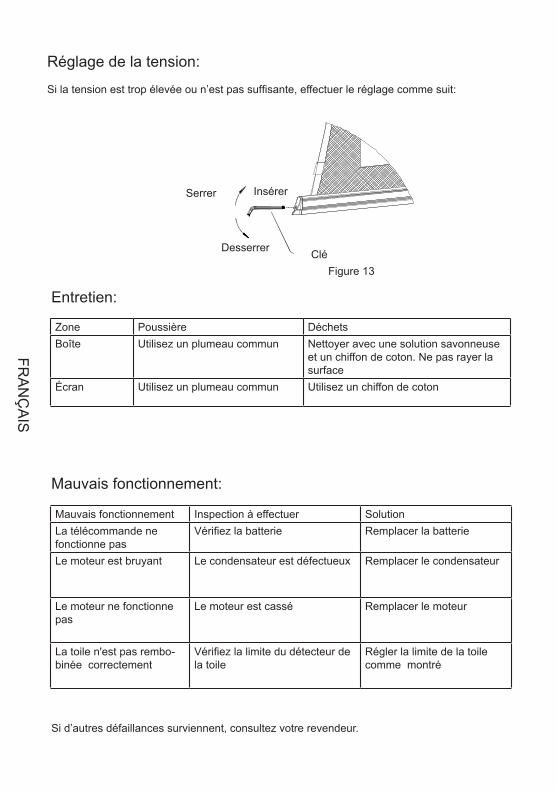
Réglage de la tension:
Si la tension est trop élevée ou n’est pas suffisante, effectuer le réglage comme suit:
Figure 13
InsérerSerrer
Desserrer Clé
Entretien:
Mauvais fonctionnement:
Si d’autres défaillances surviennent, consultez votre revendeur.
Mauvais fonctionnement Inspection à effectuer SolutionLa télécommande ne fonctionne pas
Vérifiez la batterie Remplacer la batterie
Le moteur est bruyant Le condensateur est défectueux Remplacer le condensateur
Le moteur ne fonctionne pas
Le moteur est cassé Remplacer le moteur
La toile n'est pas rembo-binée correctement
Vérifiez la limite du détecteur de la toile
Régler la limite de la toile comme montré
Zone Poussière DéchetsBoîte Utilisez un plumeau commun Nettoyer avec une solution savonneuse
et un chiffon de coton. Ne pas rayer la surface
Écran Utilisez un plumeau commun Utilisez un chiffon de coton
FRA
NÇ
AIS
If the tension is loose or over-tension, please adjust is as following fig
Tighten
Tool
Insert
Loose
(If the are any other malfunction, please consult your local approval agent)
Light dusting is possiblewith a feather duster
Area
Casing
Surface Clean with a feather duster
Dusty Dirty
Clean with a mild soap solution and dry witha lint free cloth.Take care not to scratch the casing
Use a lint brush to remove any dirt
Phenomenon *Check parts reason Processing method
*Check if the battery power off
*Capacitor broke up
*Motor broke up
*A little rolling reversal
Remote control malfunction
Abnormal sound of motor
Motor not run
Fabric rolling reversal
Replace battery
Change capacitor
Change motor
Adjust according to thechapter of adjusting" "
Figure 13
6
Réglage de la tension:
Si la tension est trop élevée ou n’est pas suffisante, effectuer le réglage comme suit:
Si d’autres défaillances surviennent, consultez votre revendeur.
Zone Poussière DéchetsBoîte Utilisez un plumeau commun Nettoyer avec une solution savonneuse
et un chiffon de coton. Ne pas rayer la surface
Écran Utilisez un plumeau commun Utilisez un chiffon de coton
1.Please do not run the screen continuously above 5minutes to avoid the motor damaged due tooverheat aging; when next operation please wait the motor cool down
2.Do not scratch or fold up the fabric.3.Afer usage, please check again there are no other foreign objectives on the screen surface and
then draw back the fabric into the case
Screen learn needle
Trigger learn needle
Cordless rigger
Remote control
Quantity
LASE R
PictureName
Hex key
Adjusting tool
Assembling plate
Expansive bolt
1
1
1
1
1
1
2
4
7
Power cord 2m(standard)5m(optional)
RS485 cord 5m
Rappelez-vous:
Ne pas faire fonctionner l’écran pendant plus de 5 minutes consécutives, car la surchauffe qui 1. en résultent pourrait dédommager le moteur, avant de procéder laisser le refroidir. Ne pas rayer ou plier toile 2. Après l’utilisation, avant d’enrouler la toile, contrôler q’il n’y a pas d’objets étrangers sur la 3. surface de l’écran.
Accessoires:
Nom
Vis tamponnée
Plaque de fixation
Outil de réglage
Clé hexagonale
Télécommande radio
Télécommande
Câble d’alimentation
Câble RS 485
2M (STANDARD)5 M (OPTIONAL)
Programmation du télécommande
Programmation de l’écran
Image Quantité
FRA
NÇ
AIS
!
Please open the carton and check accessories according to the list.Adust the position between the two plates:
1.W hen assembling, do not stand in right under the screen to avoid any hazard. Expansive boltshould be firmly punched and fixed into the wall or ceiling.
2.Be sure the ground wire is connected with power cable e�ectively to avoid electric shock3.W hen use the laser pointer function on remote control, please be sure not to point to peopledirectly to avoid any hurt.
Before installing screen, please screw off the connection plate between casing and bottom bar(Figure 1 )
Figure 1
1
Figure 2
Figure 3 Figure 4
Wall mounting
Expansive boltAssemble plate
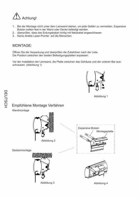
Achtung!
Bei der Montage nicht unter dem Leinwand stehen, um jede Gefahr zu vermeiden. Expansive 1. Bolzen sollten fest in der Wand oder Decke befestigt werden. überprüfen, dass das Erdungskabel richtig mit Netzkabel angeschlossen 2. Keine direkte Laser-Pointer auf die Menschen. 3.
MONTAGE:
Öffnen Sie die Verpackung und überprüfen die Zubehören nach der Liste. Die Position zwischen den beiden Befestigungsplatten anpassen:
Vor der Installation der Leinwand, die Platte zwischen das Gehäuse und der unteren Bar aus-schrauben. (Abbildung 1)
Abbildung 1
Abbildung 2
Abbildung 3 Abbildung 4
Expansive Bolzen Montageplatte
Empfohlene Montage Verfahren Wandmontage
Deckenmontage
DE
UTS
CH
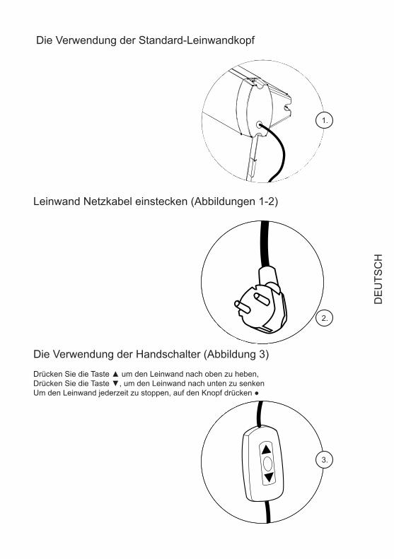
Die Verwendung der Standard-Leinwandkopf
Leinwand Netzkabel einstecken (Abbildungen 1-2)
Die Verwendung der Handschalter (Abbildung 3)
Drücken Sie die Taste ▲ um den Leinwand nach oben zu heben, Drücken Sie die Taste ▼, um den Leinwand nach unten zu senken Um den Leinwand jederzeit zu stoppen, auf den Knopf drücken ●
The screen provide four control ways: ;cordless trigger control; manual switch contr l; RS485 contr l (Figure 5)
RF remote controlo o
1.
The screen provide four control ways: ;cordless trigger control; manual switch contr l; RS485 contr l (Figure 5)
RF remote controlo o
2.
The screen provide four control ways: ;cordless trigger control; manual switch contr l; RS485 contr l (Figure 5)
RF remote controlo o
3.
DE
UTS
CH
1.Plug the power cord into the power jack on the right end cap .2.Switch on the power (within stated voltage)
1.Insert manual switch cord into the interface of right end cap
Push the button down, lift the screenPush the button up to down the screenTo stop any time while the screen is in motion,turn the button to o" "
2.Connect power on
The screen provide four control ways: ;cordless trigger control; manual switch contr l; RS485 contr l (Figure 5)
RF remote controlo o
Power Cord Jack AC 90~240VManual Switch InterfaceRS485 Interface
Learn Code Hole
Figure 5
2
Figure 6
Figure 7
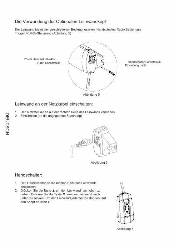
Die Verwendung der Optionalen-Leinwandkopf
Der Leinwand bietet vier verschiedenen Bedienungsarten: Handschalter, Radio Bedienung, Trigger, RS485-Steuerung (Abbildung 5)
Leinwand an der Netzkabel einschalten:
Den Netzstecker an auf der rechten Seite des Leinwands verbinden1. Einschalten (an die angegebene Spannung) 2.
Abbildung 5
Abbildung 6
Abbildung 7
Power Jack AC 90-240V RS485-Schnittstelle Handschalter Schnittstelle
Einstellung Loch
Handschalter:
Den Handschalter an die rechten Seite des Leinwands 1. einsteckenDrücken Sie die Taste ▲ um den Leinwand nach oben zu 2. heben. Drücken Sie die Taste ▼, um den Leinwand nach unten zu senken. Um den Leinwand jederzeit zu stoppen, auf den Knopf drücken ●
DE
UTS
CH
1.The remote has been set up at the factory, and should work right away. However, if you would liketo control another screen with the same control, you will need to use the learn function.
2.Make sure the manual switch is in the closed position and the switch- cord disconnected. Please pressthe hole at the right-end-cap for 3 seconds, indicated by a light flash, then press the back of remotecontrol the receiver led light at the right-end-cap will become normally on from flash situation. Now wefinish the learn code function . Please refer to remote control user manul for some details instructionabout learn code function
The remote uses a powerful anti-interference module, providing excellent stability. By using the screensbuilt-in-receiver, the screen can be controlled from as far away as 40 meters (wall will reduce the distance)
3.Please operate as follows
3
Figure 8
Figure 9
UpStopDownLaser pointer button
Remote control(Battery AAA DC 1.5V 2)
Abbildung 8
Abbildung 9
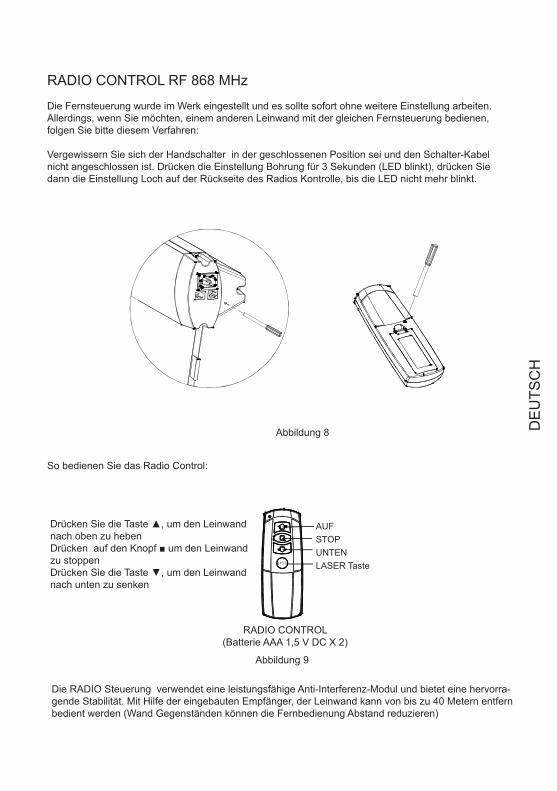
RADIO CONTROL RF 868 MHz
Die Fernsteuerung wurde im Werk eingestellt und es sollte sofort ohne weitere Einstellung arbeiten. Allerdings, wenn Sie möchten, einem anderen Leinwand mit der gleichen Fernsteuerung bedienen, folgen Sie bitte diesem Verfahren:
Vergewissern Sie sich der Handschalter in der geschlossenen Position sei und den Schalter-Kabel nicht angeschlossen ist. Drücken die Einstellung Bohrung für 3 Sekunden (LED blinkt), drücken Sie dann die Einstellung Loch auf der Rückseite des Radios Kontrolle, bis die LED nicht mehr blinkt.
So bedienen Sie das Radio Control:
AUFSTOP UNTEN LASER Taste
Drücken Sie die Taste ▲, um den Leinwand nach oben zu hebenDrücken auf den Knopf ■ um den Leinwand zu stoppen Drücken Sie die Taste ▼, um den Leinwand nach unten zu senken
RADIO CONTROL (Batterie AAA 1,5 V DC X 2)
Die RADIO Steuerung verwendet eine leistungsfähige Anti-Interferenz-Modul und bietet eine hervorra-gende Stabilität. Mit Hilfe der eingebauten Empfänger, der Leinwand kann von bis zu 40 Metern entfern bedient werden (Wand Gegenständen können die Fernbedienung Abstand reduzieren)
DE
UTS
CH
1.2.Insert the trigger directly into trigger out interface of projector,
when running the projector, the screen will down automaticallywhen closing the projector , the screen will up automatically
Make sure the manual switch is in the closed position and the switch- cord disconnected
1. Also make sureyour projector open trigger function. press the hole of right end cap 3 seconds with small touchneedle, indicated by a light flash, then press the hole in the back of cordless trigger 3 seconds, receiver
led light at the right-end-cap will become normally on from flash situation.. Now we finish the learn codefunction.
Make sure the manual switch is in the closed position and the switch- cord disconnected
Please refer to cordless trigger control user manul for some details instruction about learn codefunction.
Plug one side of the signal cord into the computer output interface at right side of the s endcap, the other side of the signal cord to plug into the interface of computer Rs485, and then you
can run the screen up/pause/down via computer.
creen's
The remote has been set up at the factory, and should work right away. Please operate as follows:
If need control another screen with the same trigger, or changed new remote control than need finish learncode again as follows.
After finishing learn code function, now, you can insert projector trigger out interface straightly. Ourpatented cordless trigger allows your screen synchronize its up and down with projector power cycle.When projector power open, the screen up ,projector power close, the screen down automatically. Orwhen projector power is open situation, you insert wireless trigger, the screen will up, take the triggeroff projector, the screen will also down automatically.
4
Figure 10
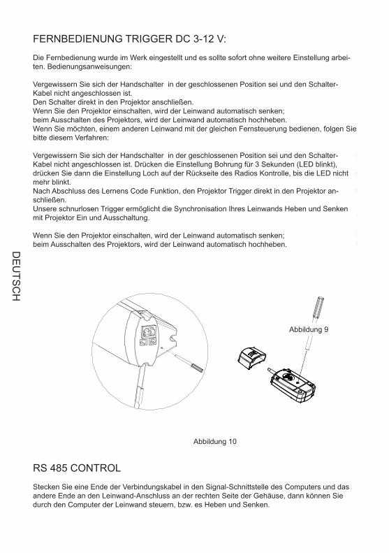
FERNBEDIENUNG TRIGGER DC 3-12 V:
Die Fernbedienung wurde im Werk eingestellt und es sollte sofort ohne weitere Einstellung arbei-ten. Bedienungsanweisungen:
Vergewissern Sie sich der Handschalter in der geschlossenen Position sei und den Schalter-Kabel nicht angeschlossen ist. Den Schalter direkt in den Projektor anschließen. Wenn Sie den Projektor einschalten, wird der Leinwand automatisch senken; beim Ausschalten des Projektors, wird der Leinwand automatisch hochheben. Wenn Sie möchten, einem anderen Leinwand mit der gleichen Fernsteuerung bedienen, folgen Sie bitte diesem Verfahren:
Vergewissern Sie sich der Handschalter in der geschlossenen Position sei und den Schalter-Kabel nicht angeschlossen ist. Drücken die Einstellung Bohrung für 3 Sekunden (LED blinkt), drücken Sie dann die Einstellung Loch auf der Rückseite des Radios Kontrolle, bis die LED nicht mehr blinkt. Nach Abschluss des Lernens Code Funktion, den Projektor Trigger direkt in den Projektor an-schließen. Unsere schnurlosen Trigger ermöglicht die Synchronisation Ihres Leinwands Heben und Senken mit Projektor Ein und Ausschaltung.
Wenn Sie den Projektor einschalten, wird der Leinwand automatisch senken; beim Ausschalten des Projektors, wird der Leinwand automatisch hochheben.
Abbildung 10
Abbildung 9
RS 485 CONTROL
Stecken Sie eine Ende der Verbindungskabel in den Signal-Schnittstelle des Computers und das andere Ende an den Leinwand-Anschluss an der rechten Seite der Gehäuse, dann können Sie durch den Computer der Leinwand steuern, bzw. es Heben und Senken.
DE
UTS
CH
Fabric is always on the right position before out of factory. However, If fabric needs adjusting, a microadjusting switch is provided. Please use a screw knife of 3mm diameter or other enclosed tool to insertinto the hole the right bottom of case for adjusting
1. Adjusting for up limited position (fabric drawing back stage)When the fabric in the stage of drawingback and the bottom shaft is not in right place, please operate as the up limited position drawing, turnas direction, the fabric will descend; turn as direction, the fabric will rise .+" " " -"
Note: please insert the tool as the showed angle.
2.Adjusting for bottom limited position (fabric completely open up) when the fabric completelyopen up, while the top black border is not in right place .please operate as the bottom limitedposition drawing ,turn as direction, the fabric will descend; turn as direction, the
fabric will rise .+" " " -"
5
Figure 11
Figure 12
Adjusting tool
Front side
Up limited adjusting
Bottom limitedadjusting
Abbildung 11
Abbildung 12
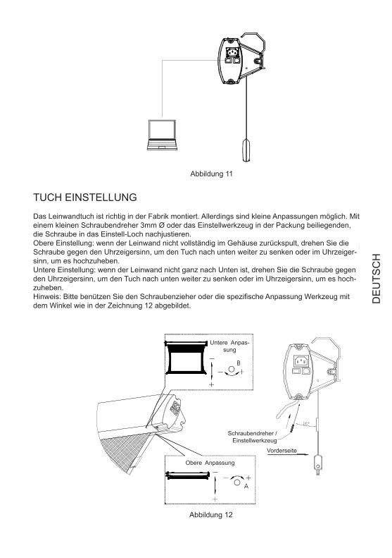
TUCH EINSTELLUNG
Das Leinwandtuch ist richtig in der Fabrik montiert. Allerdings sind kleine Anpassungen möglich. Mit einem kleinen Schraubendreher 3mm Ø oder das Einstellwerkzeug in der Packung beiliegenden, die Schraube in das Einstell-Loch nachjustieren. Obere Einstellung: wenn der Leinwand nicht vollständig im Gehäuse zurückspult, drehen Sie die Schraube gegen den Uhrzeigersinn, um den Tuch nach unten weiter zu senken oder im Uhrzeiger-sinn, um es hochzuheben. Untere Einstellung: wenn der Leinwand nicht ganz nach Unten ist, drehen Sie die Schraube gegen den Uhrzeigersinn, um den Tuch nach unten weiter zu senken oder im Uhrzeigersinn, um es hoch-zuheben. Hinweis: Bitte benützen Sie den Schraubenzieher oder die spezifische Anpassung Werkzeug mit dem Winkel wie in der Zeichnung 12 abgebildet.
Untere Anpas-sung
Obere Anpassung
Schraubendreher / Einstellwerkzeug
Vorderseite
DE
UTS
CH
If the tension is loose or over-tension, please adjust is as following fig
Tighten
Tool
Insert
Loose
(If the are any other malfunction, please consult your local approval agent)
Light dusting is possiblewith a feather duster
Area
Casing
Surface Clean with a feather duster
Dusty Dirty
Clean with a mild soap solution and dry witha lint free cloth.Take care not to scratch the casing
Use a lint brush to remove any dirt
Phenomenon *Check parts reason Processing method
*Check if the battery power off
*Capacitor broke up
*Motor broke up
*A little rolling reversal
Remote control malfunction
Abnormal sound of motor
Motor not run
Fabric rolling reversal
Replace battery
Change capacitor
Change motor
Adjust according to thechapter of adjusting" "
Figure 13
6
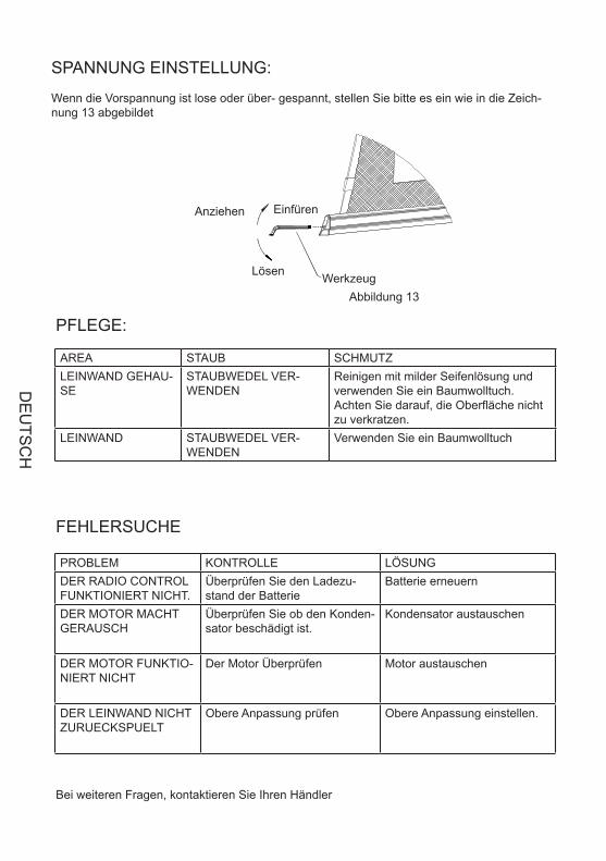
SPANNUNG EINSTELLUNG:
Wenn die Vorspannung ist lose oder über- gespannt, stellen Sie bitte es ein wie in die Zeich-nung 13 abgebildet
Abbildung 13
Einfüren Anziehen
Lösen Werkzeug
PFLEGE:
FEHLERSUCHE
Bei weiteren Fragen, kontaktieren Sie Ihren Händler
PROBLEM KONTROLLE LÖSUNGDER RADIO CONTROL FUNKTIONIERT NICHT.
Überprüfen Sie den Ladezu-stand der Batterie
Batterie erneuern
DER MOTOR MACHT GERAUSCH
Überprüfen Sie ob den Konden-sator beschädigt ist.
Kondensator austauschen
DER MOTOR FUNKTIO-NIERT NICHT
Der Motor Überprüfen Motor austauschen
DER LEINWAND NICHT ZURUECKSPUELT
Obere Anpassung prüfen Obere Anpassung einstellen.
AREA STAUB SCHMUTZLEINWAND GEHAU-SE
STAUBWEDEL VER-WENDEN
Reinigen mit milder Seifenlösung und verwenden Sie ein Baumwolltuch. Achten Sie darauf, die Oberfläche nicht zu verkratzen.
LEINWAND STAUBWEDEL VER-WENDEN
Verwenden Sie ein Baumwolltuch
DE
UTS
CH
If the tension is loose or over-tension, please adjust is as following fig
Tighten
Tool
Insert
Loose
(If the are any other malfunction, please consult your local approval agent)
Light dusting is possiblewith a feather duster
Area
Casing
Surface Clean with a feather duster
Dusty Dirty
Clean with a mild soap solution and dry witha lint free cloth.Take care not to scratch the casing
Use a lint brush to remove any dirt
Phenomenon *Check parts reason Processing method
*Check if the battery power off
*Capacitor broke up
*Motor broke up
*A little rolling reversal
Remote control malfunction
Abnormal sound of motor
Motor not run
Fabric rolling reversal
Replace battery
Change capacitor
Change motor
Adjust according to thechapter of adjusting" "
Figure 13
6
1.Please do not run the screen continuously above 5minutes to avoid the motor damaged due tooverheat aging; when next operation please wait the motor cool down
2.Do not scratch or fold up the fabric.3.Afer usage, please check again there are no other foreign objectives on the screen surface and
then draw back the fabric into the case
Screen learn needle
Trigger learn needle
Cordless rigger
Remote control
Quantity
LASE R
PictureName
Hex key
Adjusting tool
Assembling plate
Expansive bolt
1
1
1
1
1
1
2
4
7
Power cord 2m(standard)5m(optional)
RS485 cord 5m
WICHTIG :
Den Leinwand nicht kontinuierlich über 5 Minuten laufen, weil den Motor, durch überhitzen, 1. sich beschädigen konnte; bevor es weiter zu führen, warten Sie bis den Motor abkühlt Do nicht zerkratzen oder klappen Sie den Stoff. 2. Nach Verwendung, vor der Leinwand Aufzuwickeln stellen Sie es fest, es keine Fremdkörper 3. auf der Oberfläche des Leinwand gibt.
ZUBEHÖREN:
BESCHREIBUNG
SCHRAUBENBOL-ZEN
MONTAGEPLATTE
Einstellwerkzeug
Sechskantschlüssel
Radio Control
Trigger
Strom Kabel 2M Standard5 M Zubehör
Trigger Einstellung-swerkzeug
Leinwand Einstellung-swerkzeug
BILD MENGE
DE
UTS
CH
!
Please open the carton and check accessories according to the list.Adust the position between the two plates:
1.W hen assembling, do not stand in right under the screen to avoid any hazard. Expansive boltshould be firmly punched and fixed into the wall or ceiling.
2.Be sure the ground wire is connected with power cable e�ectively to avoid electric shock3.W hen use the laser pointer function on remote control, please be sure not to point to peopledirectly to avoid any hurt.
Before installing screen, please screw off the connection plate between casing and bottom bar(Figure 1 )
Figure 1
1
Figure 2
Figure 3 Figure 4
Wall mounting
Expansive boltAssemble plate
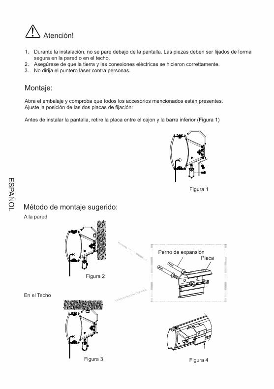
Atención!
Durante la instalación, no se pare debajo de la pantalla. Las piezas deben ser fijados de forma 1. segura en la pared o en el techo. Asegúrese de que la tierra y las conexiones eléctricas se hicieron correttamente.2. No dirija el puntero láser contra personas. 3.
Montaje:
Abra el embalaje y comproba que todos los accesorios mencionados están presentes. Ajuste la posición de las dos placas de fijación:
Antes de instalar la pantalla, retire la placa entre el cajon y la barra inferior (Figura 1)
Figura 1
Figura 2
Figura 3 Figura 4
Perno de expansión Placa
Método de montaje sugerido: A la pared
En el Techo
ES
PAÑ
OL
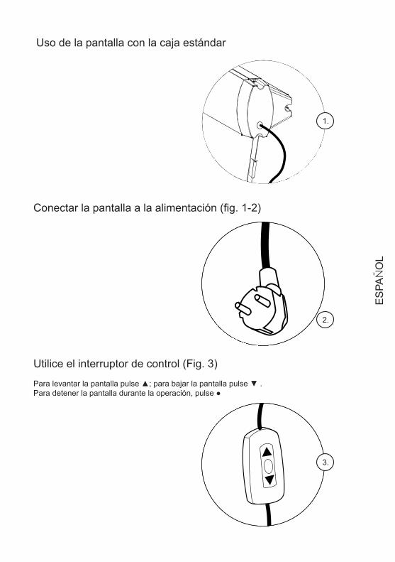
Uso de la pantalla con la caja estándar
Conectar la pantalla a la alimentación (fig. 1-2)
Utilice el interruptor de control (Fig. 3)
Para levantar la pantalla pulse ▲; para bajar la pantalla pulse ▼ . Para detener la pantalla durante la operación, pulse ●
The screen provide four control ways: ;cordless trigger control; manual switch contr l; RS485 contr l (Figure 5)
RF remote controlo o
1.
The screen provide four control ways: ;cordless trigger control; manual switch contr l; RS485 contr l (Figure 5)
RF remote controlo o
2.
The screen provide four control ways: ;cordless trigger control; manual switch contr l; RS485 contr l (Figure 5)
RF remote controlo o
3.
ES
PAÑ
OL
1.Plug the power cord into the power jack on the right end cap .2.Switch on the power (within stated voltage)
1.Insert manual switch cord into the interface of right end cap
Push the button down, lift the screenPush the button up to down the screenTo stop any time while the screen is in motion,turn the button to o" "
2.Connect power on
The screen provide four control ways: ;cordless trigger control; manual switch contr l; RS485 contr l (Figure 5)
RF remote controlo o
Power Cord Jack AC 90~240VManual Switch InterfaceRS485 Interface
Learn Code Hole
Figure 5
2
Figure 6
Figure 7
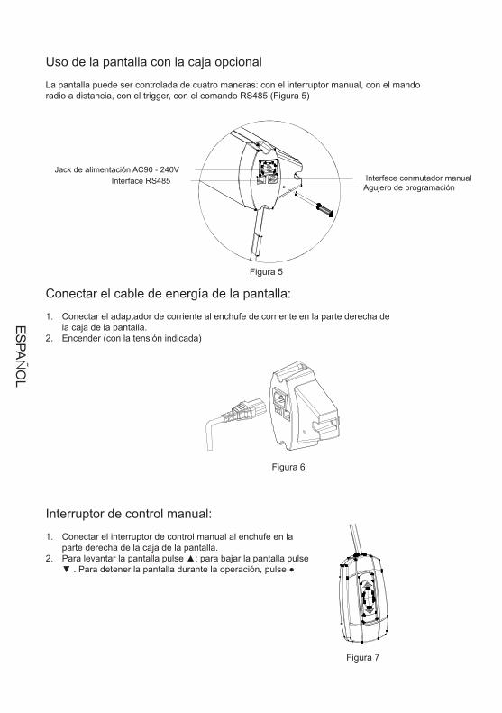
Uso de la pantalla con la caja opcional
La pantalla puede ser controlada de cuatro maneras: con el interruptor manual, con el mando radio a distancia, con el trigger, con el comando RS485 (Figura 5)
Conectar el cable de energía de la pantalla:
Conectar el adaptador de corriente al enchufe de corriente en la parte derecha de 1. la caja de la pantalla.Encender (con la tensión indicada)2.
Figura 5
Figura 6
Figura 7
Jack de alimentación AC90 - 240V Interface RS485 Interface conmutador manual
Agujero de programación
Interruptor de control manual:
Conectar el interruptor de control manual al enchufe en la 1. parte derecha de la caja de la pantalla.Para levantar la pantalla pulse ▲; para bajar la pantalla pulse 2. ▼ . Para detener la pantalla durante la operación, pulse ●
ES
PAÑ
OL
1.The remote has been set up at the factory, and should work right away. However, if you would liketo control another screen with the same control, you will need to use the learn function.
2.Make sure the manual switch is in the closed position and the switch- cord disconnected. Please pressthe hole at the right-end-cap for 3 seconds, indicated by a light flash, then press the back of remotecontrol the receiver led light at the right-end-cap will become normally on from flash situation. Now wefinish the learn code function . Please refer to remote control user manul for some details instructionabout learn code function
The remote uses a powerful anti-interference module, providing excellent stability. By using the screensbuilt-in-receiver, the screen can be controlled from as far away as 40 meters (wall will reduce the distance)
3.Please operate as follows
3
Figure 8
Figure 9
UpStopDownLaser pointer button
Remote control(Battery AAA DC 1.5V 2)
Figura 8
Figura 9
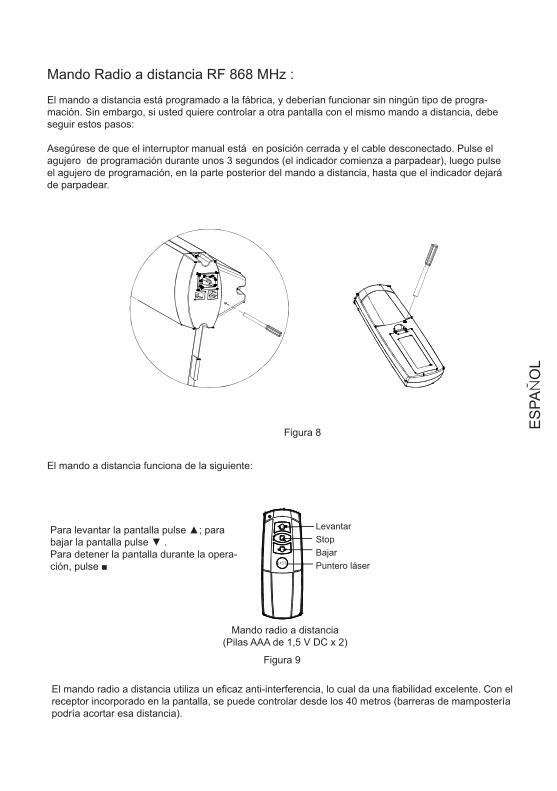
Mando Radio a distancia RF 868 MHz :
El mando a distancia está programado a la fábrica, y deberían funcionar sin ningún tipo de progra-mación. Sin embargo, si usted quiere controlar a otra pantalla con el mismo mando a distancia, debe seguir estos pasos:
Asegúrese de que el interruptor manual está en posición cerrada y el cable desconectado. Pulse el agujero de programación durante unos 3 segundos (el indicador comienza a parpadear), luego pulse el agujero de programación, en la parte posterior del mando a distancia, hasta que el indicador dejará de parpadear.
El mando a distancia funciona de la siguiente:
Levantar Stop Bajar Puntero láser
Para levantar la pantalla pulse ▲; para bajar la pantalla pulse ▼ . Para detener la pantalla durante la opera-ción, pulse ■
Mando radio a distancia(Pilas AAA de 1,5 V DC x 2)
El mando radio a distancia utiliza un eficaz anti-interferencia, lo cual da una fiabilidad excelente. Con el receptor incorporado en la pantalla, se puede controlar desde los 40 metros (barreras de mampostería podría acortar esa distancia).
ES
PAÑ
OL
1.2.Insert the trigger directly into trigger out interface of projector,
when running the projector, the screen will down automaticallywhen closing the projector , the screen will up automatically
Make sure the manual switch is in the closed position and the switch- cord disconnected
1. Also make sureyour projector open trigger function. press the hole of right end cap 3 seconds with small touchneedle, indicated by a light flash, then press the hole in the back of cordless trigger 3 seconds, receiver
led light at the right-end-cap will become normally on from flash situation.. Now we finish the learn codefunction.
Make sure the manual switch is in the closed position and the switch- cord disconnected
Please refer to cordless trigger control user manul for some details instruction about learn codefunction.
Plug one side of the signal cord into the computer output interface at right side of the s endcap, the other side of the signal cord to plug into the interface of computer Rs485, and then you
can run the screen up/pause/down via computer.
creen's
The remote has been set up at the factory, and should work right away. Please operate as follows:
If need control another screen with the same trigger, or changed new remote control than need finish learncode again as follows.
After finishing learn code function, now, you can insert projector trigger out interface straightly. Ourpatented cordless trigger allows your screen synchronize its up and down with projector power cycle.When projector power open, the screen up ,projector power close, the screen down automatically. Orwhen projector power is open situation, you insert wireless trigger, the screen will up, take the triggeroff projector, the screen will also down automatically.
4
Figure 10
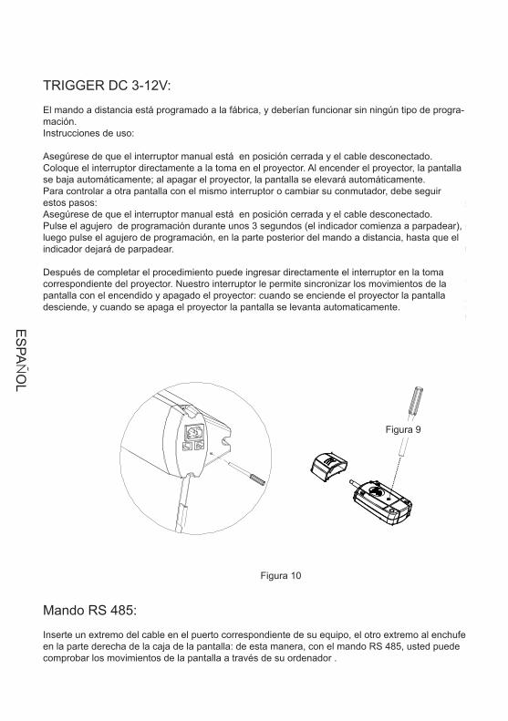
TRIGGER DC 3-12V:
El mando a distancia está programado a la fábrica, y deberían funcionar sin ningún tipo de progra-mación.Instrucciones de uso:
Asegúrese de que el interruptor manual está en posición cerrada y el cable desconectado.Coloque el interruptor directamente a la toma en el proyector. Al encender el proyector, la pantalla se baja automáticamente; al apagar el proyector, la pantalla se elevará automáticamente. Para controlar a otra pantalla con el mismo interruptor o cambiar su conmutador, debe seguir estos pasos: Asegúrese de que el interruptor manual está en posición cerrada y el cable desconectado.Pulse el agujero de programación durante unos 3 segundos (el indicador comienza a parpadear), luego pulse el agujero de programación, en la parte posterior del mando a distancia, hasta que el indicador dejará de parpadear.
Después de completar el procedimiento puede ingresar directamente el interruptor en la toma correspondiente del proyector. Nuestro interruptor le permite sincronizar los movimientos de la pantalla con el encendido y apagado el proyector: cuando se enciende el proyector la pantalla desciende, y cuando se apaga el proyector la pantalla se levanta automaticamente.
Figura 10
Figura 9
Mando RS 485:
Inserte un extremo del cable en el puerto correspondiente de su equipo, el otro extremo al enchufe en la parte derecha de la caja de la pantalla: de esta manera, con el mando RS 485, usted puede comprobar los movimientos de la pantalla a través de su ordenador .
ES
PAÑ
OL
Fabric is always on the right position before out of factory. However, If fabric needs adjusting, a microadjusting switch is provided. Please use a screw knife of 3mm diameter or other enclosed tool to insertinto the hole the right bottom of case for adjusting
1. Adjusting for up limited position (fabric drawing back stage)When the fabric in the stage of drawingback and the bottom shaft is not in right place, please operate as the up limited position drawing, turnas direction, the fabric will descend; turn as direction, the fabric will rise .+" " " -"
Note: please insert the tool as the showed angle.
2.Adjusting for bottom limited position (fabric completely open up) when the fabric completelyopen up, while the top black border is not in right place .please operate as the bottom limitedposition drawing ,turn as direction, the fabric will descend; turn as direction, the
fabric will rise .+" " " -"
5
Figure 11
Figure 12
Adjusting tool
Front side
Up limited adjusting
Bottom limitedadjusting
Figura 11
Figura 12
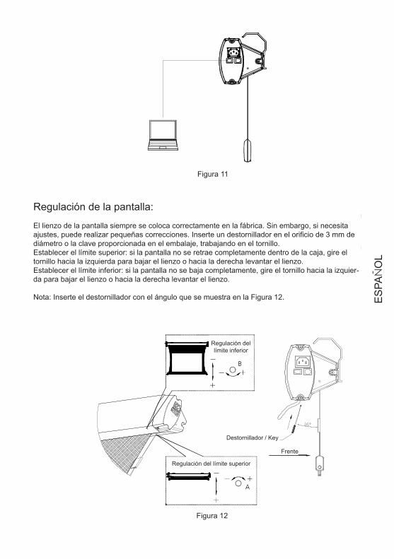
Regulación de la pantalla:
El lienzo de la pantalla siempre se coloca correctamente en la fábrica. Sin embargo, si necesita ajustes, puede realizar pequeñas correcciones. Inserte un destornillador en el orificio de 3 mm de diámetro o la clave proporcionada en el embalaje, trabajando en el tornillo. Establecer el límite superior: si la pantalla no se retrae completamente dentro de la caja, gire el tornillo hacia la izquierda para bajar el lienzo o hacia la derecha levantar el lienzo. Establecer el límite inferior: si la pantalla no se baja completamente, gire el tornillo hacia la izquier-da para bajar el lienzo o hacia la derecha levantar el lienzo.
Nota: Inserte el destornillador con el ángulo que se muestra en la Figura 12.
Regulación del límite inferior
Regulación del límite superior
Destornillador / Key
Frente
ES
PAÑ
OL
If the tension is loose or over-tension, please adjust is as following fig
Tighten
Tool
Insert
Loose
(If the are any other malfunction, please consult your local approval agent)
Light dusting is possiblewith a feather duster
Area
Casing
Surface Clean with a feather duster
Dusty Dirty
Clean with a mild soap solution and dry witha lint free cloth.Take care not to scratch the casing
Use a lint brush to remove any dirt
Phenomenon *Check parts reason Processing method
*Check if the battery power off
*Capacitor broke up
*Motor broke up
*A little rolling reversal
Remote control malfunction
Abnormal sound of motor
Motor not run
Fabric rolling reversal
Replace battery
Change capacitor
Change motor
Adjust according to thechapter of adjusting" "
Figure 13
6
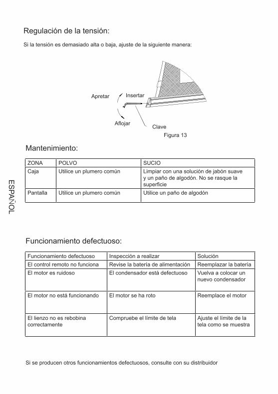
Regulación de la tensión:
Si la tensión es demasiado alta o baja, ajuste de la siguiente manera:
Figura 13
Insertar Apretar
Aflojar Clave
Mantenimiento:
Funcionamiento defectuoso:
Si se producen otros funcionamientos defectuosos, consulte con su distribuidor
Funcionamiento defectuoso Inspección a realizar SoluciónEl control remoto no funciona Revise la batería de alimentación Reemplazar la bateríaEl motor es ruidoso El condensador está defectuoso Vuelva a colocar un
nuevo condensador
El motor no está funcionando El motor se ha roto Reemplace el motor
El lienzo no es rebobina correctamente
Compruebe el límite de tela Ajuste el límite de la tela como se muestra
ZONA POLVO SUCIOCaja Utilice un plumero común Limpiar con una solución de jabón suave
y un paño de algodón. No se rasque la superficie
Pantalla Utilice un plumero común Utilice un paño de algodón
ES
PAÑ
OL
If the tension is loose or over-tension, please adjust is as following fig
Tighten
Tool
Insert
Loose
(If the are any other malfunction, please consult your local approval agent)
Light dusting is possiblewith a feather duster
Area
Casing
Surface Clean with a feather duster
Dusty Dirty
Clean with a mild soap solution and dry witha lint free cloth.Take care not to scratch the casing
Use a lint brush to remove any dirt
Phenomenon *Check parts reason Processing method
*Check if the battery power off
*Capacitor broke up
*Motor broke up
*A little rolling reversal
Remote control malfunction
Abnormal sound of motor
Motor not run
Fabric rolling reversal
Replace battery
Change capacitor
Change motor
Adjust according to thechapter of adjusting" "
Figure 13
6
Regulación de la tensión:
Si la tensión es demasiado alta o baja, ajuste de la siguiente manera:
Si se producen otros funcionamientos defectuosos, consulte con su distribuidor
1.Please do not run the screen continuously above 5minutes to avoid the motor damaged due tooverheat aging; when next operation please wait the motor cool down
2.Do not scratch or fold up the fabric.3.Afer usage, please check again there are no other foreign objectives on the screen surface and
then draw back the fabric into the case
Screen learn needle
Trigger learn needle
Cordless rigger
Remote control
Quantity
LASE R
PictureName
Hex key
Adjusting tool
Assembling plate
Expansive bolt
1
1
1
1
1
1
2
4
7
Power cord 2m(standard)5m(optional)
RS485 cord 5m
Recuerde:
No haga funcionar la pantalla durante más de 5 minutos consecutivos, ya que el sobrecalen-1. tamiento consiguiente daño el motor; deje que se enfríe antes de seguir en la operación.No se rasque o se doble la tela.2. Después de su utilización, antes de rebobinar el lienzo, comprobar que no hay objetos ex-3. traños en la superficie.
Accesorios:
Nombre
Perno de expansión
Placa de fijación
Herramienta de ajuste
Llave hexagonal
Mando radio a distancia
Mando a distancia
Cable de alimentación
Cable RS 485
2m (standard)5m (opcional)
Reprogramación del mando radio a distancia
Reprogramación de la pantalla
Imagen Cantidad
ES
PAÑ
OL

14.0
4.20
10


![Cyberpunk 2020 [Schermo Del Master]](https://img.pdfslide.tips/doc/110x75/5695cf481a28ab9b028d66f3/cyberpunk-2020-schermo-del-master-5709edb5e7823.jpg)


![[Cyberpunk 2020] - Schermo Del Master](https://img.pdfslide.tips/doc/110x75/5571f22449795947648c3c11/cyberpunk-2020-schermo-del-master.jpg)