Embed Size (px)
Citation preview
1©2007 The Tokyo Electric Power Company , INC. All Rights Reserved
TEPCO's experiences of automatic voltage controllers and SIPS as measures
to prevent massive power outages
Shinichi Imai, [email protected]
Teruo [email protected]
The Tokyo Electric Power Company, Inc.
2©2007 The Tokyo Electric Power Company , INC. All Rights Reserved
Hokkaido EPCO
Hokuriku EPCO
Chubu EPCO
Chugoku EPCO
Okinawa EPCO
Kyushu EPCOShikoku EPCO
Kansai EPCO
TEPCO Tokyo EPCO
Tohoku EPCO
North Latitude
Wholesale: J-POWER (EPDC)The Japan Atomic Power Company, etc.
East Longitude
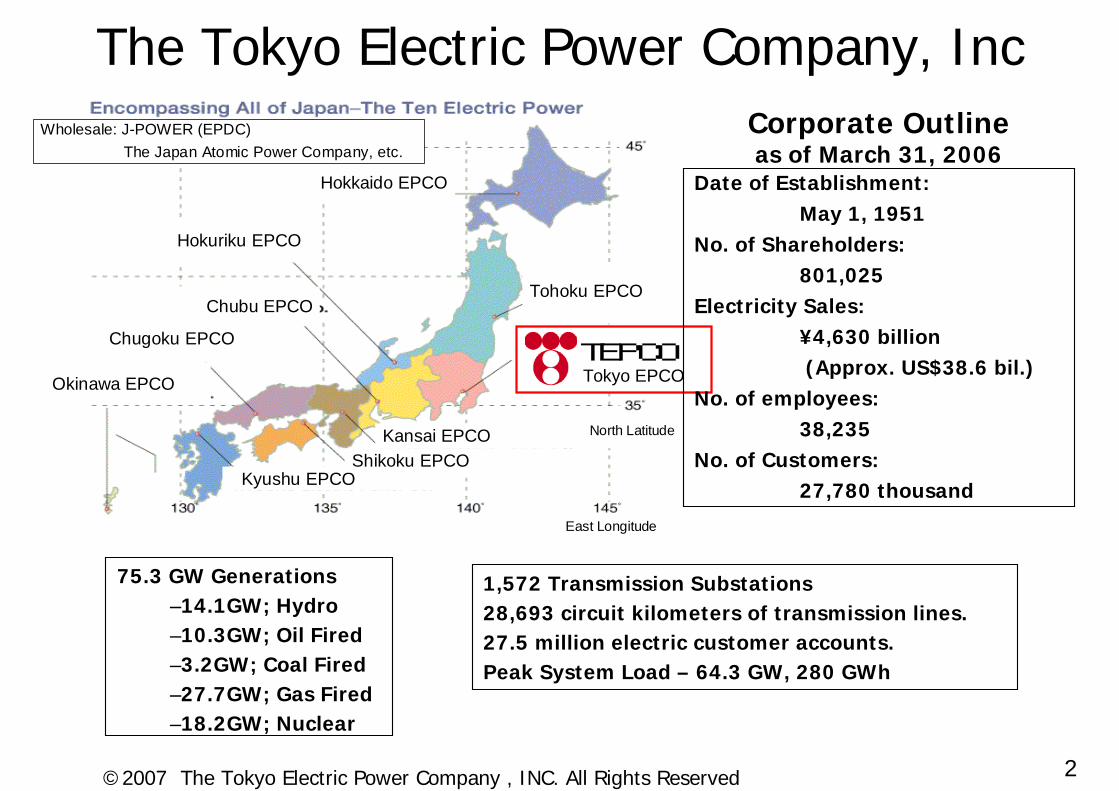
Date of Establishment:May 1, 1951
No. of Shareholders:801,025
Electricity Sales:¥4,630 billion(Approx. US$38.6 bil.)
No. of employees:38,235
No. of Customers:27,780 thousand
Corporate Outlineas of March 31, 2006
75.3 GW Generations–14.1GW; Hydro–10.3GW; Oil Fired–3.2GW; Coal Fired–27.7GW; Gas Fired–18.2GW; Nuclear
The Tokyo Electric Power Company, Inc
1,572 Transmission Substations28,693 circuit kilometers of transmission lines.27.5 million electric customer accounts.Peak System Load – 64.3 GW, 280 GWh
3©2007 The Tokyo Electric Power Company , INC. All Rights Reserved
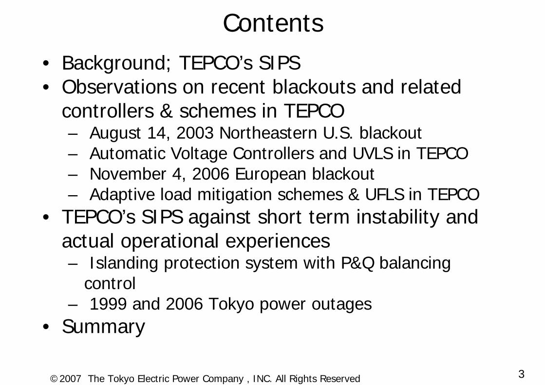
Contents• Background; TEPCO’s SIPS• Observations on recent blackouts and related
controllers & schemes in TEPCO– August 14, 2003 Northeastern U.S. blackout– Automatic Voltage Controllers and UVLS in TEPCO– November 4, 2006 European blackout– Adaptive load mitigation schemes & UFLS in TEPCO
• TEPCO’s SIPS against short term instability and actual operational experiences– Islanding protection system with P&Q balancing
control– 1999 and 2006 Tokyo power outages
• Summary
4©2007 The Tokyo Electric Power Company , INC. All Rights Reserved
BackgroundTEPCO’s System Integrity Protection Schemes
5©2007 The Tokyo Electric Power Company , INC. All Rights Reserved
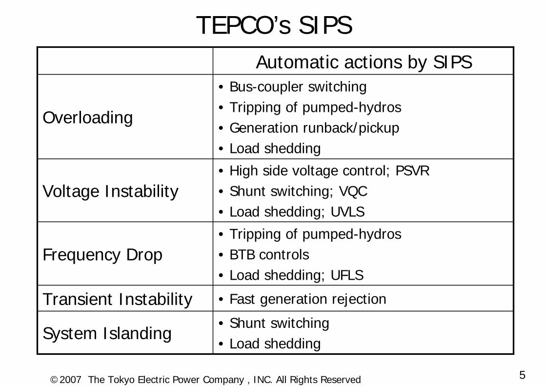
TEPCO’s SIPS
• Shunt switching• Load shedding
System Islanding
• Fast generation rejectionTransient Instability
• Tripping of pumped-hydros• BTB controls• Load shedding; UFLS
Frequency Drop
• High side voltage control; PSVR• Shunt switching; VQC• Load shedding; UVLS
Voltage Instability
• Bus-coupler switching• Tripping of pumped-hydros• Generation runback/pickup• Load shedding
Overloading
Automatic actions by SIPS
6©2007 The Tokyo Electric Power Company , INC. All Rights Reserved
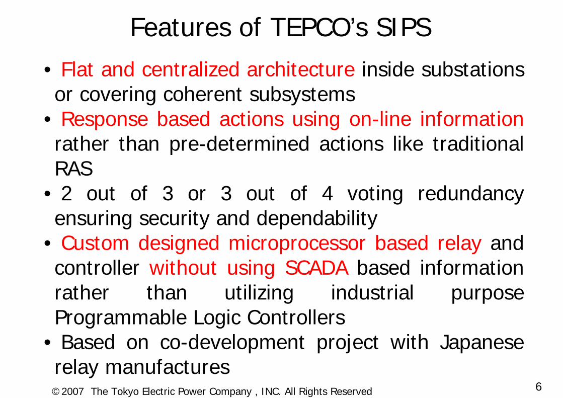
Features of TEPCO’s SIPS• Flat and centralized architecture inside substations or covering coherent subsystems
• Response based actions using on-line informationrather than pre-determined actions like traditional RAS
• 2 out of 3 or 3 out of 4 voting redundancy ensuring security and dependability
• Custom designed microprocessor based relay and controller without using SCADA based information rather than utilizing industrial purpose Programmable Logic Controllers
• Based on co-development project with Japanese relay manufactures
7©2007 The Tokyo Electric Power Company , INC. All Rights Reserved
Observations on recent blackouts and related controllers &
schemes in TEPCO
8©2007 The Tokyo Electric Power Company , INC. All Rights Reserved
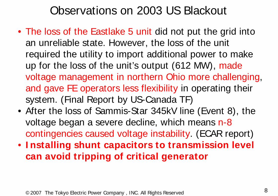
Observations on 2003 US Blackout
• The loss of the Eastlake 5 unit did not put the grid into an unreliable state. However, the loss of the unit required the utility to import additional power to make up for the loss of the unit’s output (612 MW), made voltage management in northern Ohio more challenging, and gave FE operators less flexibility in operating their system. (Final Report by US-Canada TF)
• After the loss of Sammis-Star 345kV line (Event 8), the voltage began a severe decline, which means n-8 contingencies caused voltage instability. (ECAR report)
• Installing shunt capacitors to transmission level can avoid tripping of critical generator
9©2007 The Tokyo Electric Power Company , INC. All Rights Reserved
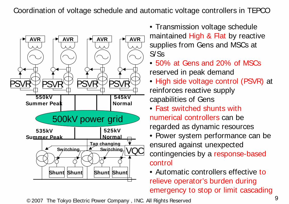
Coordination of voltage schedule and automatic voltage controllers in TEPCO
• Transmission voltage schedule maintained High & Flat by reactive supplies from Gens and MSCs at S/Ss• 50% at Gens and 20% of MSCsreserved in peak demand• High side voltage control (PSVR) at reinforces reactive supply capabilities of Gens• Fast switched shunts with numerical controllers can be regarded as dynamic resources• Power system performance can be ensured against unexpected contingencies by a response-based control• Automatic controllers effective to relieve operator’s burden during emergency to stop or limit cascading
AVR
PSVR
AVR AVR AVR
VQCTap changing
Switching Switching
550kVSummer Peak
535kVSummer Peak
545kVNormal
525kVNormal
500kV power grid
Shunt Shunt Shunt Shunt
PSVR PSVR PSVR

10©2007 The Tokyo Electric Power Company , INC. All Rights Reserved
UVLS as Last Resort• Installed just after 1987 Tokyo
Blackout: Longest operation history of the world
• Microprocessor-based relaying• Voltage collapse is detected:
– by central units located in the 500kV network, because 275kV or lower voltage are regulated by tap changing
– based on 3 out of 4 decision making logic to avoid unwanted operation
• Central units detect:– Voltage Drop (Under Voltage)– Rate of Voltage drop (dV/dt)
500kV Main Grid
CUCU
CU
Communication; Voltage collapse detection result
Communication; Measured 500kV voltages
(CU: Central Unit)
Sub-Station275,154/66
275kV,154kV radial network
CU
Sub-Station275,154/66
RTU
RTU
11©2007 The Tokyo Electric Power Company , INC. All Rights Reserved
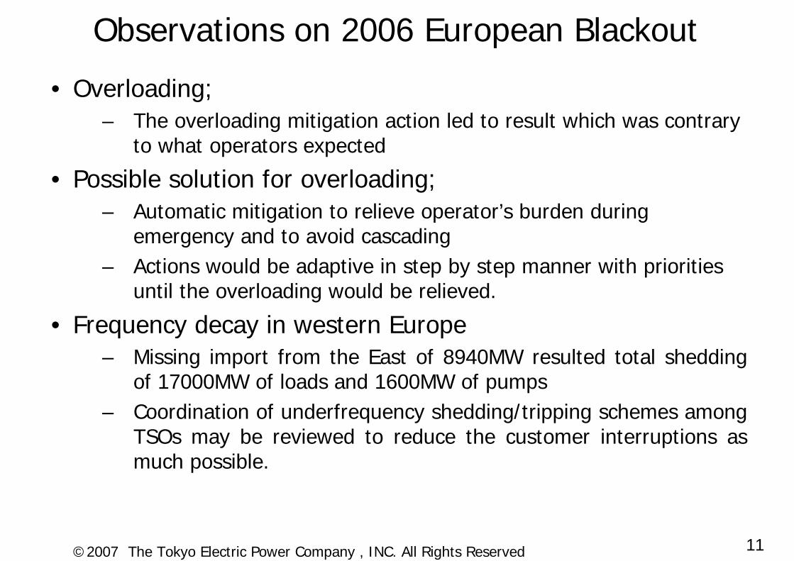
Observations on 2006 European Blackout
• Overloading;– The overloading mitigation action led to result which was contrary
to what operators expected
• Possible solution for overloading;– Automatic mitigation to relieve operator’s burden during
emergency and to avoid cascading– Actions would be adaptive in step by step manner with priorities
until the overloading would be relieved.
• Frequency decay in western Europe– Missing import from the East of 8940MW resulted total shedding
of 17000MW of loads and 1600MW of pumps– Coordination of underfrequency shedding/tripping schemes among
TSOs may be reviewed to reduce the customer interruptions as much possible.
12©2007 The Tokyo Electric Power Company , INC. All Rights Reserved
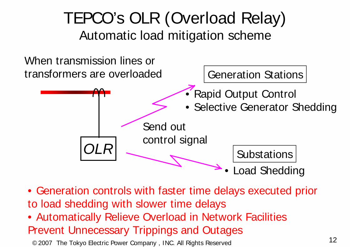
TEPCO’s OLR (Overload Relay)Automatic load mitigation scheme
OLR
When transmission lines ortransformers are overloaded
Send outcontrol signal
Generation Stations
• Rapid Output Control• Selective Generator Shedding
Substations• Load Shedding
• Generation controls with faster time delays executed prior to load shedding with slower time delays• Automatically Relieve Overload in Network FacilitiesPrevent Unnecessary Trippings and Outages
13©2007 The Tokyo Electric Power Company , INC. All Rights Reserved
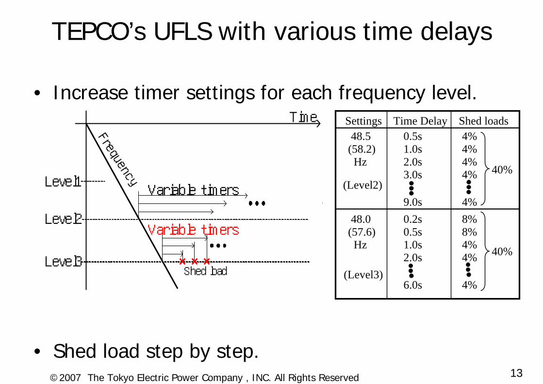
• Increase timer settings for each frequency level.
• Shed load step by step.
TEPCO’s UFLS with various time delays
Settings Time Delay Shed loads48.5
(58.2)Hz
0.5s 4%1.0s 4%2.0s 4%3.0s 4%
9.0s 4%48.0
(57.6)Hz
0.2s 8%0.5s 8%1.0s 4%2.0s 4%
6.0s 4%
40%
40%
Time
Level2
Variable timers
Level3
Shed load
Level1
Frequency
Time
Level2
Level3
Variable timers
Shed load
Level1Variable timers
Frequency (Level2)
(Level3)
14©2007 The Tokyo Electric Power Company , INC. All Rights Reserved
TEPCO’s SIPS against short term instability and actual operational
experiences
15©2007 The Tokyo Electric Power Company , INC. All Rights Reserved
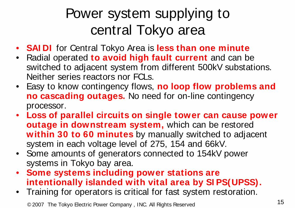
Power system supplying to central Tokyo area
• SAIDI for Central Tokyo Area is less than one minute• Radial operated to avoid high fault current and can be
switched to adjacent system from different 500kV substations. Neither series reactors nor FCLs.
• Easy to know contingency flows, no loop flow problems and no cascading outages. No need for on-line contingency processor.
• Loss of parallel circuits on single tower can cause power outage in downstream system, which can be restored within 30 to 60 minutes by manually switched to adjacent system in each voltage level of 275, 154 and 66kV.
• Some amounts of generators connected to 154kV power systems in Tokyo bay area.
• Some systems including power stations are intentionally islanded with vital area by SIPS(UPSS).
• Training for operators is critical for fast system restoration.

16©2007 The Tokyo Electric Power Company , INC. All Rights Reserved
Metropolitan Area including Tokyo
TEPCO’s bulk power gridG
G
G
G
G
• 500kV; Meshed configuration and meshed operation
• 275kV and below; Meshed configuration and Radial operation
500kV
275kV
500kV
500kV
17©2007 The Tokyo Electric Power Company , INC. All Rights Reserved
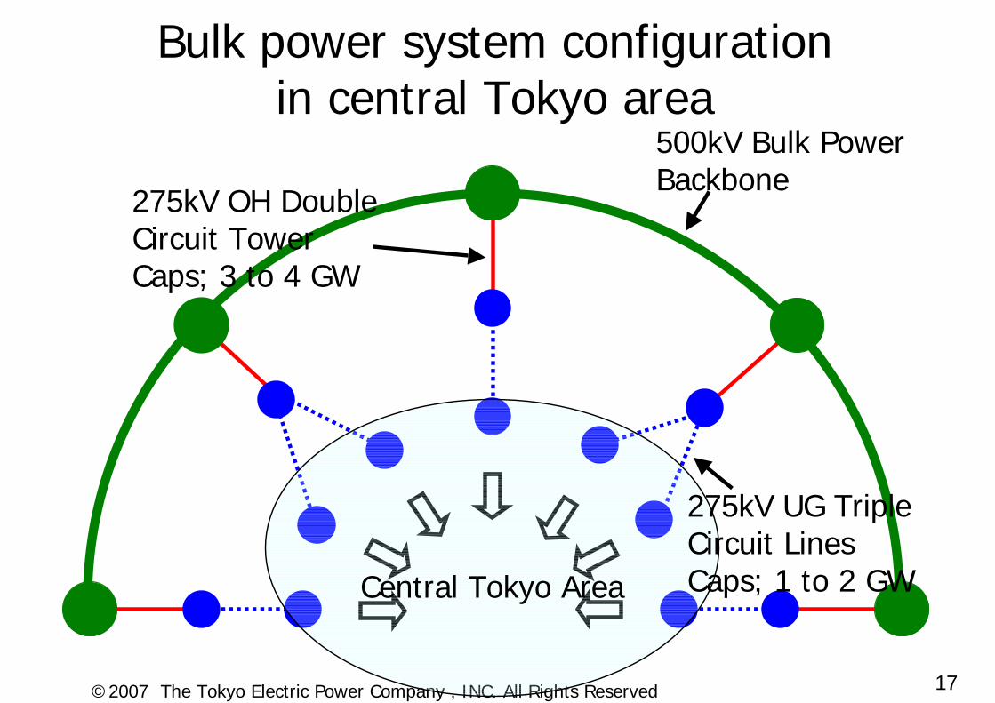
Bulk power system configuration in central Tokyo area
500kV Bulk Power Backbone
Central Tokyo Area
275kV OH Double Circuit TowerCaps; 3 to 4 GW
275kV UG Triple Circuit LinesCaps; 1 to 2 GW
18©2007 The Tokyo Electric Power Company , INC. All Rights Reserved
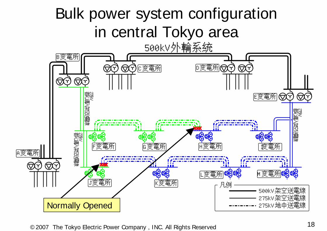
Bulk power system configuration in central Tokyo area
500kV外輪系統
275kV都心導入架空送電線
275kV都心導入架空送電線
275kV都心導入架空送電線
500kV架空送電線275kV架空送電線275kV地中送電線
凡例
A変電所
B変電所
C変電所 D変電所
E変電所
F変電所 G変電所 H変電所 I変電所
J変電所 K変電所
L変電所 M変電所
Normally Opened
19©2007 The Tokyo Electric Power Company , INC. All Rights Reserved
500kV Power Grid
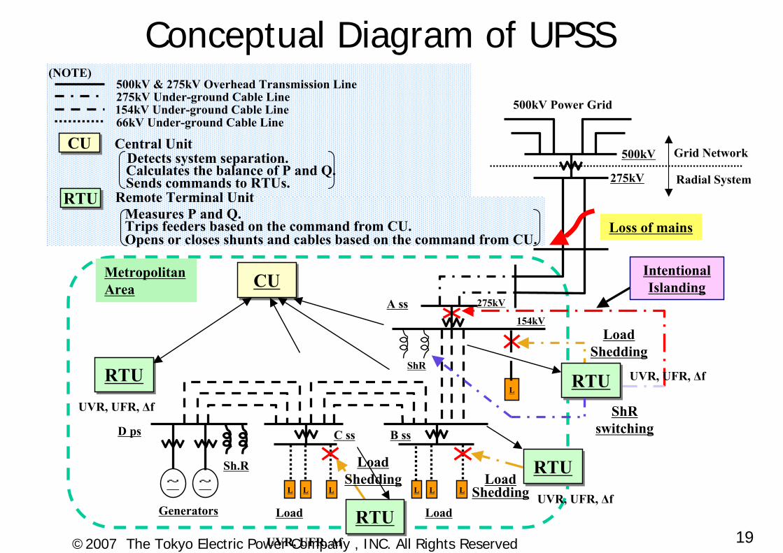
IntentionalIslandingCUCU
RTURTU
~ ~ L L L L LL
L
RTURTU
Generators Load
LoadShedding
Sh.R
C ssD ps B ss
Load
Load Shedding
154kV
275kVA ss
ShR
Loss of mains
500kV
275kV
LoadShedding
(NOTE)
Metropolitan Area
RTURTUShR
switching
RTURTU
UVR, UFR, ∆f
UVR, UFR, ∆f
UVR, UFR, ∆f
UVR, UFR, ∆f
RTURTU Remote Terminal UnitMeasures P and Q.Trips feeders based on the command from CU.Opens or closes shunts and cables based on the command from CU.
CUCU Central UnitDetects system separation.Calculates the balance of P and Q.Sends commands to RTUs.
500kV & 275kV Overhead Transmission Line275kV Under-ground Cable Line154kV Under-ground Cable Line66kV Under-ground Cable Line
Radial System
Grid Network
Conceptual Diagram of UPSS
20©2007 The Tokyo Electric Power Company , INC. All Rights Reserved
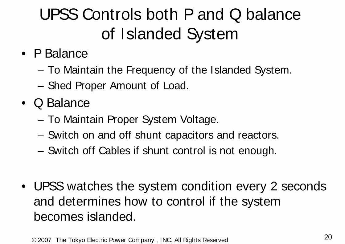
UPSS Controls both P and Q balance of Islanded System
• P Balance– To Maintain the Frequency of the Islanded System.– Shed Proper Amount of Load.
• Q Balance– To Maintain Proper System Voltage. – Switch on and off shunt capacitors and reactors.– Switch off Cables if shunt control is not enough.
• UPSS watches the system condition every 2 seconds and determines how to control if the system becomes islanded.
21©2007 The Tokyo Electric Power Company , INC. All Rights Reserved
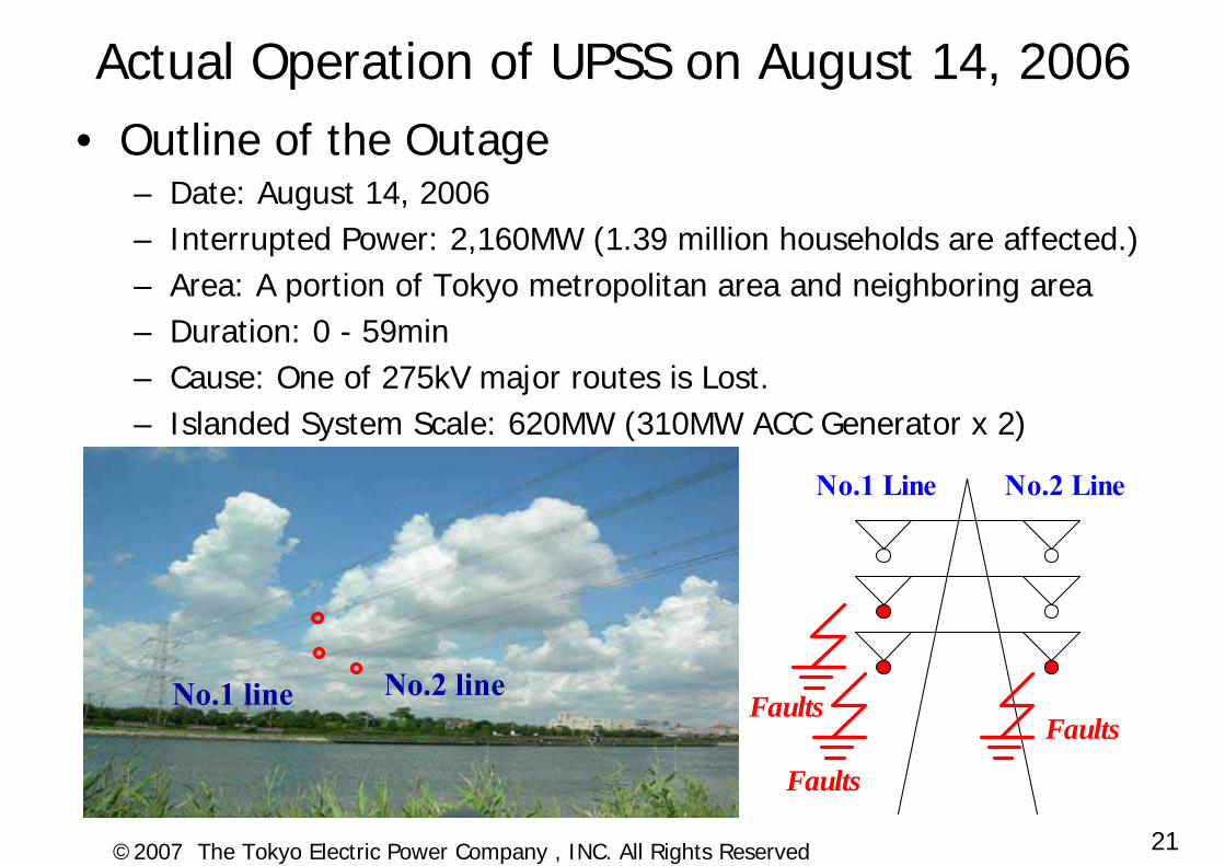
No.1 line No.2 line
No.1 Line No.2 Line
Faults
Faults
Faults
Actual Operation of UPSS on August 14, 2006• Outline of the Outage
– Date: August 14, 2006– Interrupted Power: 2,160MW (1.39 million households are affected.)– Area: A portion of Tokyo metropolitan area and neighboring area– Duration: 0 - 59min– Cause: One of 275kV major routes is Lost.– Islanded System Scale: 620MW (310MW ACC Generator x 2)

22©2007 The Tokyo Electric Power Company , INC. All Rights Reserved
No.1 Line No.2 LineUpper Phases
Middle Phases
L ower Phases
Distance between lower phases and
surface of the river 16.2m
No.1 Line No.2 LineUpper Phases
Middle Phases
L ower Phases
Distance between lower phases and
surface of the river 16.2m
Conductors of lines were severely damaged
A Crane Vessel Crashed into Transmission Lines.
(53feet)
23©2007 The Tokyo Electric Power Company , INC. All Rights Reserved
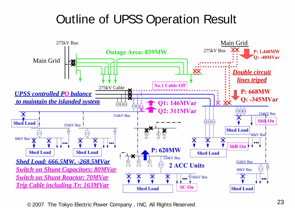
Main Grid
G G G
3T 2T 1T
G GG1-3 1-11-2
P: 1,440MWQ: -40MVar
P: 668MWQ: -345MVar
Double circuit lines triped
Shed Load: 666.5MW, -268.5MVarSwitch on Shunt Capacitors: 80MVarSwitch on Shunt Reactor: 70MVarTrip Cable including Tr: 163MVar
Shed Load Shed Load Shed Load
Shed Load Shed Load
Shed LoadShed Load
No.1 Cable Off
UPSS controlled PQ balance to maintain the islanded system
Outage Area: 839MWMain Grid
275kV Bus275kV Bus
275kV Cable
P: 620MW
2 ACC Units
154kV Bus 154kV Bus
66kV Bus
154kV Bus
66kV Bus
154kV Bus
66kV Bus
154kV Bus
66kV Bus
Q1: 146MVarQ2: 311MVar
ShR On
ShR On
SC On
Outline of UPSS Operation Result
24©2007 The Tokyo Electric Power Company , INC. All Rights Reserved
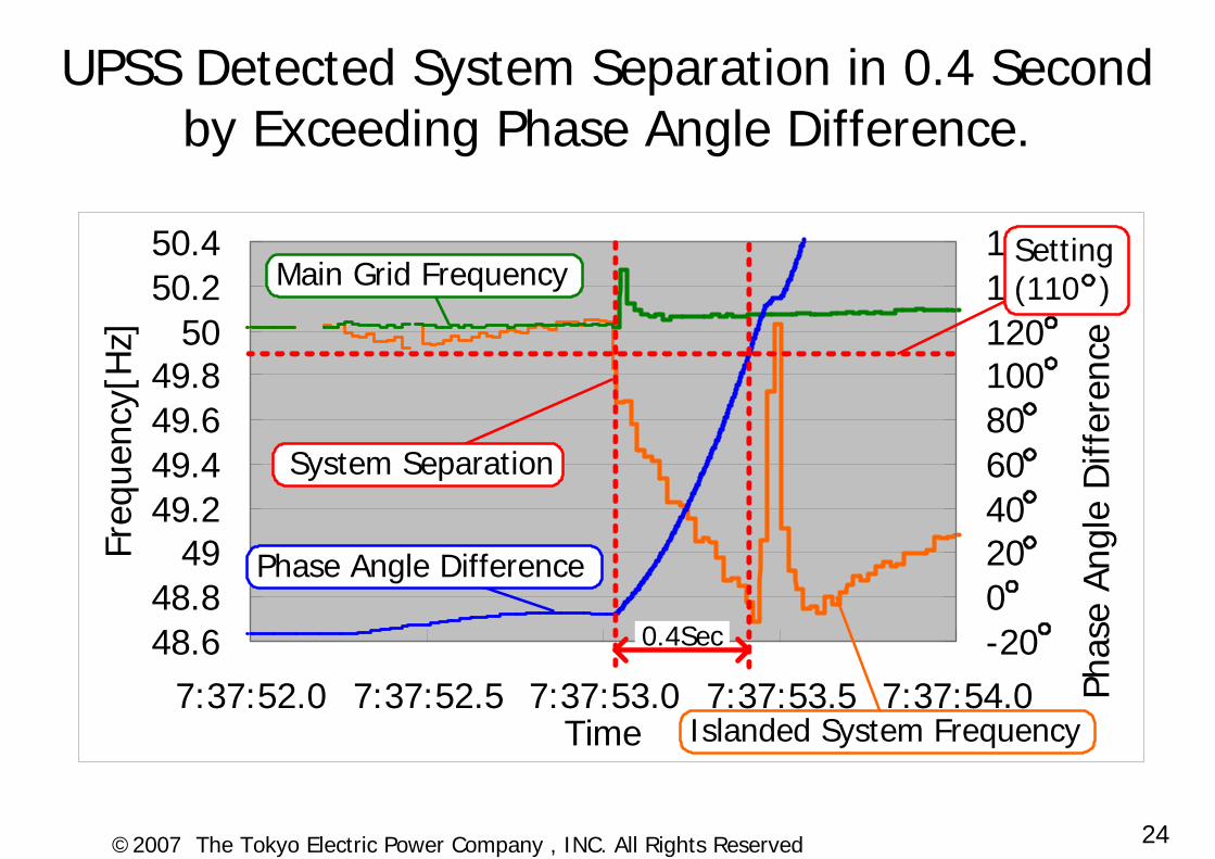
UPSS Detected System Separation in 0.4 Secondby Exceeding Phase Angle Difference.
48.648.8
4949.249.449.649.8
5050.250.4
7:37:52.0 7:37:52.5 7:37:53.0 7:37:53.5 7:37:54.0Time
Freq
uenc
e[H
z]
-20020406080100120140160
Phas
e An
gle
Diff
eren
ce
Setting(110 )
System Separation
0.4Sec
Phase Angle Difference
Main Grid Frequency
Islanded System Frequency
Freq
uenc
y[H
z]
Phas
e An
gle
Diff
eren
ce
25©2007 The Tokyo Electric Power Company , INC. All Rights Reserved
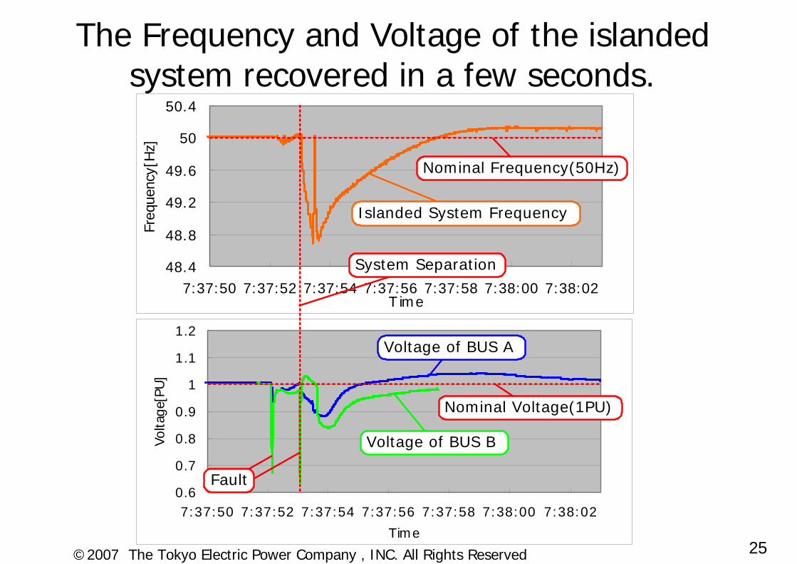
The Frequency and Voltage of the islanded system recovered in a few seconds.
0.6
0.7
0.8
0.9
1
1.1
1.2
7:37:50 7:37:52 7:37:54 7:37:56 7:37:58 7:38:00 7:38:02
Time
Volta
ge[P
U]
48.4
48.8
49.2
49.6
50
50.4
7:37:50 7:37:52 7:37:54 7:37:56 7:37:58 7:38:00 7:38:02T ime
Freq
uenc
y[H
z]
Islanded System Frequency
Voltage of BUS B
System Separation
Voltage of BUS A
Nominal Frequency(50Hz)
Fault
Nominal Voltage(1PU)
26©2007 The Tokyo Electric Power Company , INC. All Rights Reserved
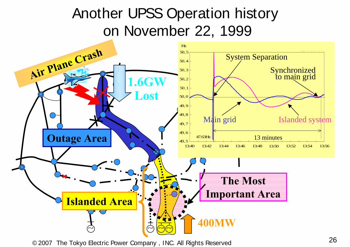
The Most Important Area
~ ~ ~ ~
Air Plane Crash
Another UPSS Operation historyon November 22, 1999
400MW
49.5
49.6
49.7
49.8
49.9
50.0
50.1
50.2
50.3
50.4
50.5
13:40 13:42 13:44 13:46 13:48 13:50 13:52 13:54 13:56時刻
Hz 本系統都心単独系統
13分
51.2Hz
47.63Hz 13 minutes
System SeparationSynchronized
Main grid Islanded system
Outage Area
1.6GWLost
Islanded Area
to main grid
27©2007 The Tokyo Electric Power Company , INC. All Rights Reserved
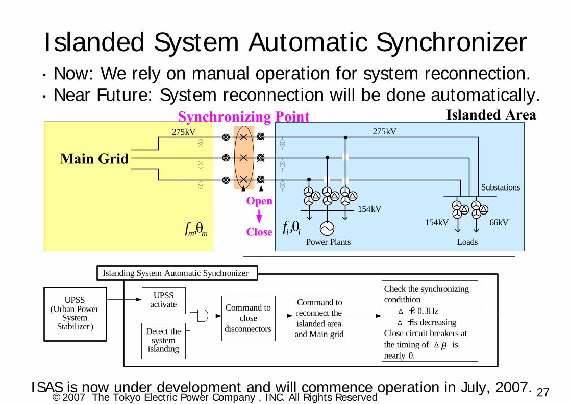
mm,f θ
UPSSactivateUPSS
(Urban Power System
Stabilizer)
Islanding System Automatic Synchronizer
Detect the system
islanding
Command to reconnect the islanded area and Main grid
275kV
154kV
Power Plants
Substations
66kV154kV
Command to close
disconnectors
Check the synchronizing condithion Δf< 0.3HzΔf is decreasing
Close circuit breakers at the timing of Δ is nearly 0.
Islanded Area
Main Grid
Synchronizing Point275kV
Loads
Open
Close ii ,f θmm,f θ
・ Now: We rely on manual operation for system reconnection.・ Near Future: System reconnection will be done automatically.
Islanded System Automatic Synchronizer
ISAS is now under development and will commence operation in July, 2007.
28©2007 The Tokyo Electric Power Company , INC. All Rights Reserved
Challenges for future• Retaining and keeping expertise especially for
system design and testing• Accelerated obsolescence of microprocessor
based technology and spare parts problem• Utilization of standardized technologies, products
and communication protocols• Sophisticated automated system restoration• Coordinated setting and tuning among voltage
controllers and SIPS by conducting many numerical calculations by more efficient manner
• Utilization of fast, reliable and high accurate data and information collected from whole of TEPCO’spower system with synchronization.

29©2007 The Tokyo Electric Power Company , INC. All Rights Reserved
Questions or Comments
30©2007 The Tokyo Electric Power Company , INC. All Rights Reserved
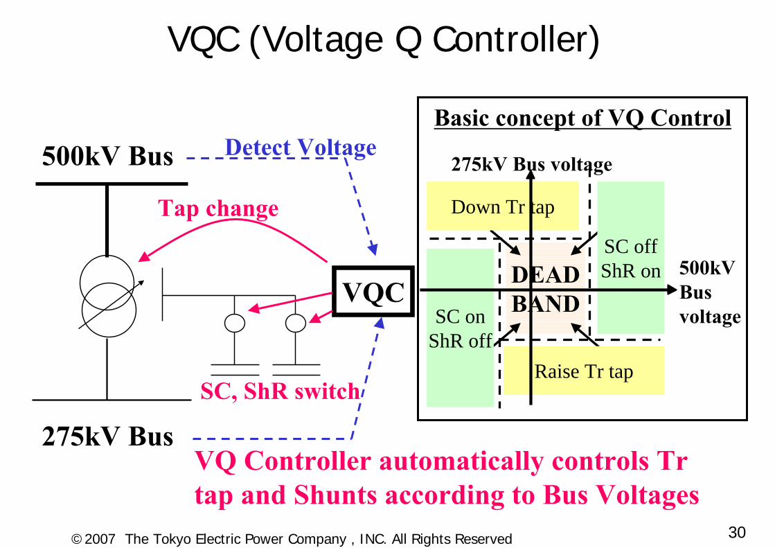
VQC (Voltage Q Controller)
275kV Bus voltage
DEADBAND
SC offShR on
SC onShR off
Down Tr tap
Raise Tr tap
500kV Bus voltage
500kV Bus
275kV BusSC, ShR switch
Tap change
Detect Voltage
VQC
VQ Controller automatically controls Trtap and Shunts according to Bus Voltages
Basic concept of VQ Control
31©2007 The Tokyo Electric Power Company , INC. All Rights Reserved
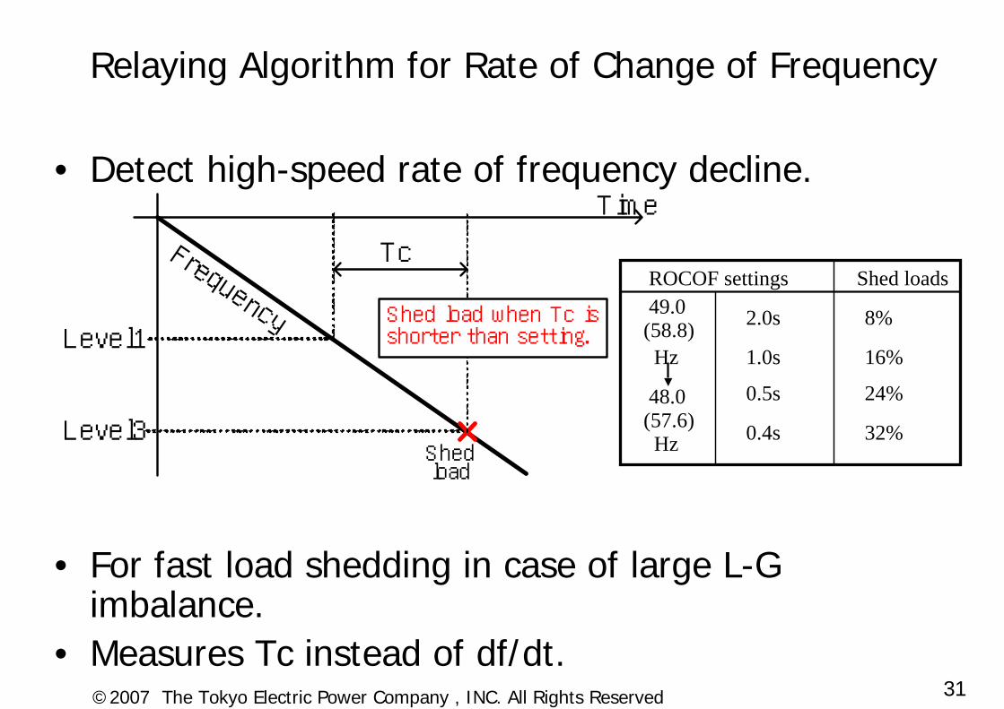
• Detect high-speed rate of frequency decline.
• For fast load shedding in case of large L-G imbalance.
• Measures Tc instead of df/dt.
Relaying Algorithm for Rate of Change of Frequency
ROCOF settings Shed loads49.0
(58.8)Hz
2.0s 8%
1.0s 16%
0.5s 24%
0.4s 32%
48.0(57.6)Hz
Time
FrequencyLevel1
Level3Shedload
Shed load when Tc isshorter than setting.
Tc
32©2007 The Tokyo Electric Power Company , INC. All Rights Reserved
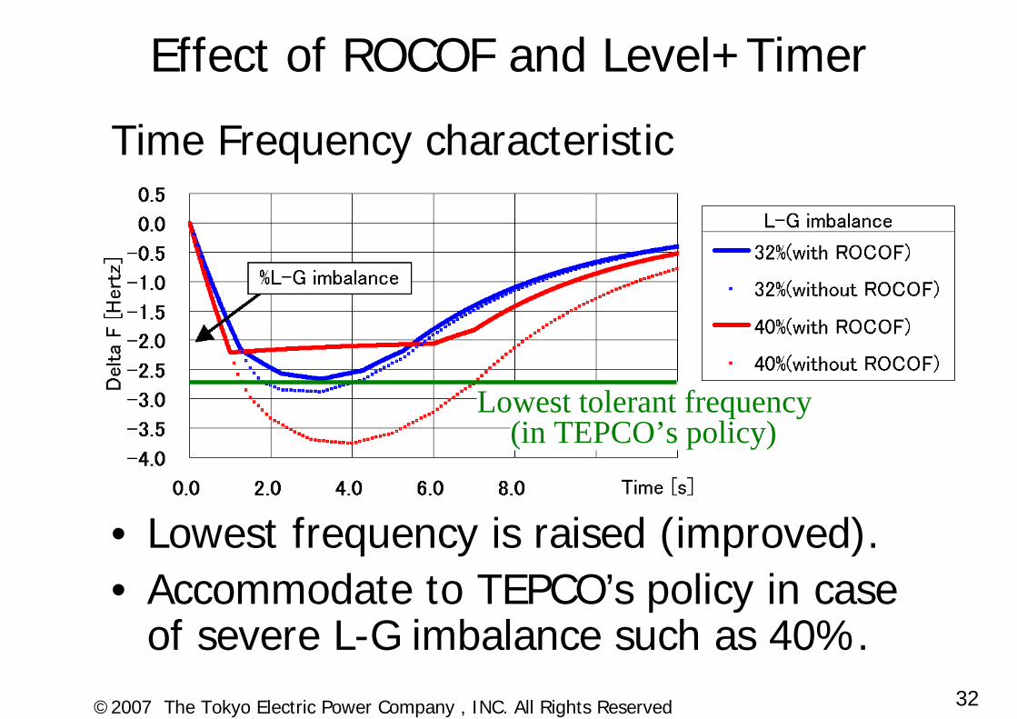
Effect of ROCOF and Level+Timer
Time Frequency characteristic
• Lowest frequency is raised (improved).• Accommodate to TEPCO’s policy in case
of severe L-G imbalance such as 40%.
(in TEPCO’s policy)Lowest tolerant frequency
33©2007 The Tokyo Electric Power Company , INC. All Rights Reserved
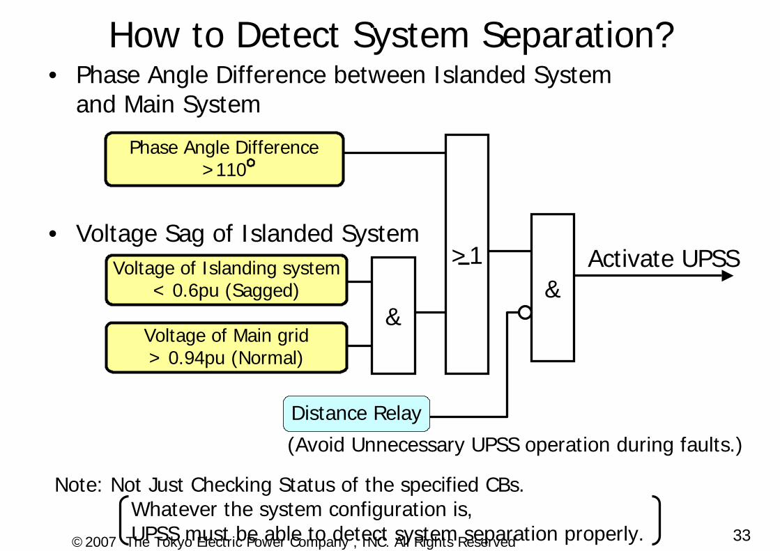
How to Detect System Separation?• Phase Angle Difference between Islanded System
and Main System
• Voltage Sag of Islanded System
&
>1Voltage of Islanding system < 0.6pu (Sagged)
Voltage of Main grid> 0.94pu (Normal)
Phase Angle Difference>110
(Avoid Unnecessary UPSS operation during faults.)
&
Distance Relay
Activate UPSS
Note: Not Just Checking Status of the specified CBs.Whatever the system configuration is, UPSS must be able to detect system separation properly.
34©2007 The Tokyo Electric Power Company , INC. All Rights Reserved
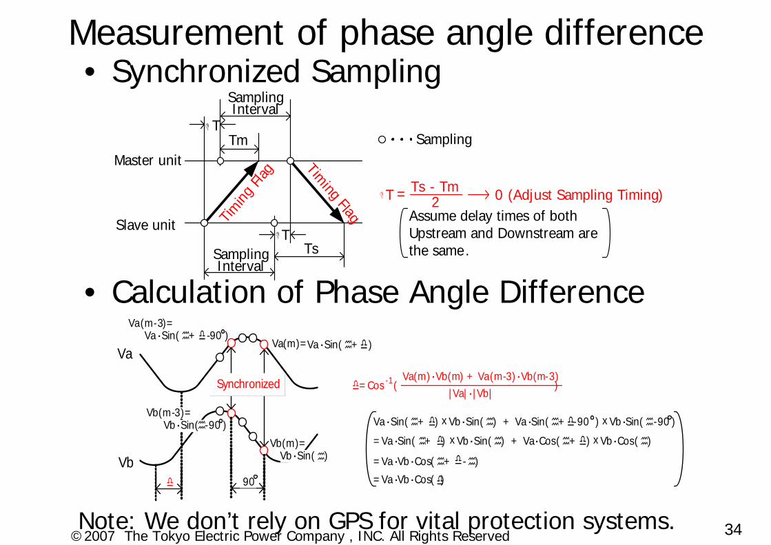
Measurement of phase angle difference• Synchronized Sampling
• Calculation of Phase Angle Difference
Note: We don’t rely on GPS for vital protection systems.
Va
Vb
Synchronized
Va・Sin( + -90 )Va・Sin( + )
Vb・Sin( )
Vb・Sin( -90 )
90
Va(m)=
Va(m-3)=
Vb(m-3)=
Vb(m)=
Va(m)・Vb(m) + Va(m-3)・Vb(m-3) -1|Va|・|Vb|
=Cos ( )
Va・Sin( + ) Vb・Sin( ) + Va・Sin( + -90 ) Vb・Sin( -90 )x x
=Va・Vb・Cos( + - )
=Va・Vb・Cos( )
=Va・Sin( + ) Vb・Sin( ) + Va・Cos( + ) Vb・Cos( )x x
Master unit
Slave unit Timin
g Fla
g
TmT
Timing Flag
TsT
Sampling Interval
Assume delay times of both Upstream and Downstream are the same.
T Ts - Tm2= 0 (Adjust Sampling Timing)
Sampling Interval
Sampling

35©2007 The Tokyo Electric Power Company , INC. All Rights Reserved
P
Failure
Main Grid
PowerStation
L L
L L
SubstationSubstation
SC
L L
ShR
α
Substation
L
L L
X~
~
β2
Q1 Q2
β1
L
275kV154kV 275kV
275kV154kV
66 kV
66 kV
Substation
P: Excess Active Power which was received from the main grid. The same amount of load must be shed to maintain the frequency.Q1, Q2: Reactive Power which was passing the central transformer of the islanded system must be maintained to keep voltage proper.
α : Detection point of receiving Active Powerwhich is used for Load shedding Calculation.
β : Detection points of passing Reactive Powerwhich is used for Voltage Control Calculation.
Simplified Power System Model for Active & Reactive Power Balance Calculation


![PowerPoint 프레젠테이션 - donar.messe.de · [ Capacitor Bank ] Your happy life, Hankwang Electric is always with you A. Genea - Low / Medium / High Voltage Capacitor Bank Automatic](https://img.pdfslide.tips/doc/110x75/5d505f3788c993e54b8be690/powerpoint-donarmessede-capacitor-bank-your-happy.jpg)