Embed Size (px)
Citation preview
Tel: +45 8691 5542
Fax: +45 7734 4371
Mobile +45 2096 8598
EC VAT no.: DK3159 2585
www.ChimneyLab.dk [email protected]
ChimneyLab Europe ApS
Godthaabsvej 6
DK-8370 Hadsten
Test report Requested by ........................... Näldens Värmeindustri AB Date ....................... 02-06-2011 Contact person ........................ Mr Carlolof Hallström Page ....................... 1 of 22 Address .................................... Näldenvägen 40 No of appendices . 3 Town ......................................... SE-83540 Nälden Country ..................................... Sweden Telephone ................................ +0046 0640-681160 Email ......................................... [email protected]
Report no ................................. ChimneyLab-101 Order no ................................... 0232
Product: Manufacturer ........................... Näldens Värmeindustri AB, Sweden Function ................................... Chimney Type .......................................... NVI 2000 Serial no ................................... -
Received date .......................... 12-05-2011 Test date................................... 18-05-2011 – 30-05-2011 Procedure................................. Thermal test according to EN 1856-1:2009 and EN 1859:2009,
Paragraph 4.5, only heat stress test and different test rig.
Results ..................................... See Chapter 5 Conclusion ............................... See Chapter 6 Terms ........................................ This test report or extracts from it may not be reproduced without the written
permission of ChimneyLab Europe ApS. The test results concern only the tested objects.
Lyngaa, Denmark 02-06-2011
Finn Petersen Process Engineer
ChimneyLabEurope
Date: 02-06-2011 Report No. ChimneyLab-101 Page 2 of 22
E:\ChimneyLab\A Prøvninger\ChimneyLab-101 NVI Finsk prøvning\ChimneyLab-101 Report.doc
Table of Content
1. Introduction ............................................................................................................................... 3
2. Description of test specimen ..................................................................................................... 3
2.1. Double wall steel chimney .............................................................................................. 3
3. Test description ......................................................................................................................... 4
3.1. Gas tightness test............................................................................................................. 4
3.2. Thermal test ChimneyLab-101-A ................................................................................... 4
3.3. Thermal test ChimneyLab-101-B ................................................................................... 9
3.4. Thermal test ChimneyLab-101-C ................................................................................. 14
4. Instrumentation ....................................................................................................................... 19
5. Test results .............................................................................................................................. 20
5.1. Thermal results ChimneyLab-101-A ............................................................................ 20
5.2. Thermal results ChimneyLab-101-B ............................................................................ 21
5.3. Thermal results ChimneyLab-101-C ............................................................................ 21
6. Conclusion .............................................................................................................................. 22
7. Remarks .................................................................................................................................. 22
Appendices
Appendix 1: Thermal results
Appendix 2: Paroc pipe section 140
Appendix 3: Rockwool wired mat 105
ChimneyLabEurope
Date: 02-06-2011 Report No. ChimneyLab-101 Page 3 of 22
E:\ChimneyLab\A Prøvninger\ChimneyLab-101 NVI Finsk prøvning\ChimneyLab-101 Report.doc
1. Introduction
The purpose of this test is to determine the chimney thermal behaviour with insulated floor
penetration.
The thermal performance test was accomplished according to EN 1856-1:2009 and EN
1859:2009, paragraph 4.5, only heat stress test, and with modified test rig, which is described in
paragraph 3.
The test was carried out at ChimneyLab Europe ApS in Lyngaa, Denmark, by Process Engineer
Finn Petersen.
2. Description of test specimen
2.1. Double wall steel chimney
The test specimen is a black modular chimney, consisting of two circular steel pipes.
Between the two pipes is 60 mm insulation.
The tested chimney has a nominal diameter of 190 mm.
The standard modular length is 1170 mm, and the construction length 1150 mm. The chimney
modules are provided with nipple and sleeve, which gives a depth of the insert joint of 30 mm
for the outer pipe.
The cylindrical joints of the outer pipe are provided with circular beads, and secured by locking
bands which cover the joint. The width of the locking bands is 44 mm.
There are no metallic connections between inner and outer pipe.
Between the two pipes is 60 mm insulation, Paroc Pro Section 140 ALC F2, which is aluminium
coated on the outside, and is delivered in 1 whole piece. The insulation has a nominal density of
140 kg/m3 and a thermal conductivity of 0,083 W ∙ m-1 ∙ K-1 at an average temperature of 300
°C (without aluminium coating).
According to EN 1856-1:2009, paragraph 6.5.2, the inner pipe is manufactured in material type
60 (material no.1.4436) with a wall thickness of 1,0 mm.
The outer pipe is manufactured in hot-dip galvanized powder coated sheet steel and has a wall
thickness of 0,70 mm.
The chimney is CE-marked with the certificate number 0402-CPD-265403.
ChimneyLabEurope
Date: 02-06-2011 Report No. ChimneyLab-101 Page 4 of 22
E:\ChimneyLab\A Prøvninger\ChimneyLab-101 NVI Finsk prøvning\ChimneyLab-101 Report.doc
3. Test description
3.1. Gas tightness test
The chimney is classified as pressure type N1. As the chimney is already CE-marked, no gas
tightness tests are performed.
3.2. Thermal test ChimneyLab-101-A
Thermal test according to EN 1859:2009, paragraph 4.5, but the test rig is a modified type, to
enable test of penetrations with insulation heights up to 1000 mm. The test rig has only 1st floor
penetration, and no walls, since the critical temperatures are in the 1st floor penetration.
The chimney was mounted in modified thermal test rig with a distance of 102 mm to
combustibles,, and in 1st floor penetration the chimney was insulated with Paroc Pro Lock
Section 140, with an insulation height of 800 mm.
The pipe section has a nominal inner diameter of 324 mm and the outer diameter is 518 mm.
Between the chimney and pipe section is an air gap of approx. 5 mm.
The pipe section has a nominal density of 140 kg/m3 and a thermal conductivity of 0,083 W ∙ m-
1 ∙ K-1 at an average temperature of 300 °C
A blank ceiling plate was mounted below 1st floor. In the air gap between the chimney and the
ceiling plate was mounted a silicon rubber sealing.
Temperature sensors were mounted on combustibles in the test rig according to EN 1859:2000
Annex E (1) but with a distance of 100 mm between the thermocouples. Temperature sensor for
flue gas temperature was placed 50 mm before inlet of the tee.
Flue gas is generated by an LPG (Light Propane Gas) burner with a nominal thermal output of
90 kW.
The flue gas temperature is controlled via a programmable temperature controller and a thermal
mass flow controller.
Flue gas flow according to EN 1859:2009, Table 1, is controlled by the combustion air flow,
which is delivered to the combustion chamber by a centrifugal ventilator.
For this chimney, with a nominal diameter of 190 mm, the flue gas flow is set to 134 Nm3/h for
550 °C flue gas temperature.

ChimneyLabEurope
Date: 02-06-2011 Report No. ChimneyLab-101 Page 5 of 22
E:\ChimneyLab\A Prøvninger\ChimneyLab-101 NVI Finsk prøvning\ChimneyLab-101 Report.doc
Photo 1: Chimney installed in test rig
Photo 2: Top of floor penetration

ChimneyLabEurope
Date: 02-06-2011 Report No. ChimneyLab-101 Page 6 of 22
E:\ChimneyLab\A Prøvninger\ChimneyLab-101 NVI Finsk prøvning\ChimneyLab-101 Report.doc
Side 1
TE 1.1-1.5
Position of thermocouples
A A
Joist 1st floor
80
0
980
10
0
23
00
Side 3
TE 3.1-3.5
Side 4
TE 4.1-4.5
Side 1
TE 1.1 to 1.5
A-A
Joist 1st floor
Side 2
TE 2.1 to 2.5
Side 3
TE 3.1 to 3.5Side 4
TE 4.1 to 4.5
Air gap 7,5 mm
520
330
556
315
X = Thermocouples on combustibles
1 = Ceiling plate
2 = Sealing between chimney and ceiling plate
3 = Costumer insulation in floor penetration
4 = Building insulation
1
2
3
4
21
00
95
0
Figure 1: Test ChimneyLab-101-A
Position of thermocouples

ChimneyLabEurope
Date: 02-06-2011 Report No. ChimneyLab-101 Page 7 of 22
E:\ChimneyLab\A Prøvninger\ChimneyLab-101 NVI Finsk prøvning\ChimneyLab-101 Report.doc
The chimney was mounted and tested under the following conditions:
Test no. ChimneyLab-101-A
Temperature class T450
Pressure class N1
Soot fire test (1000 °C) No
Distance to walls in zone B, mm -
Shaft in zone B -
1st floor penetration:
Distance to combustibles, mm 102
Ceiling plate below floor penetration Yes
Air gap between lower ceiling plate and chimney, mm 0
Rubber gasket on lower ceiling plate Yes
Ceiling plate above floor penetration No
Air gap between upper ceiling plate and chimney, mm -
Rubber gasket on upper ceiling plate -
Insulation height in floor penetration, mm 800
Insulation type in floor penetration Air gap/Paroc Pro Section 140
Table 1: Test conditions

ChimneyLabEurope
Date: 02-06-2011 Report No. ChimneyLab-101 Page 8 of 22
E:\ChimneyLab\A Prøvninger\ChimneyLab-101 NVI Finsk prøvning\ChimneyLab-101 Report.doc
The chimney was tested in the following order:
Test order Description EN 1859:2009
Paragraph
1 Installation of chimney in thermal test rig. 4.5.3
2 Heat stress test T450 1st time
550 °C until steady state
4.5.3.1
Table 2: Thermal test order
Chimney elements used for the test were weighted and measured before installation:
Element
No.
Description Color Total
weight
kg
1 Tee Black 12,44
2 0,55 m section Black 9,21
3 0,55 m section Black 9,30
4 1,2 m section Black 18,64
5 1,2 m section Black 19,09
6 0,55 m section Black 9,01
Table 3: Chimney elements used in the test
ChimneyLabEurope
Date: 02-06-2011 Report No. ChimneyLab-101 Page 9 of 22
E:\ChimneyLab\A Prøvninger\ChimneyLab-101 NVI Finsk prøvning\ChimneyLab-101 Report.doc
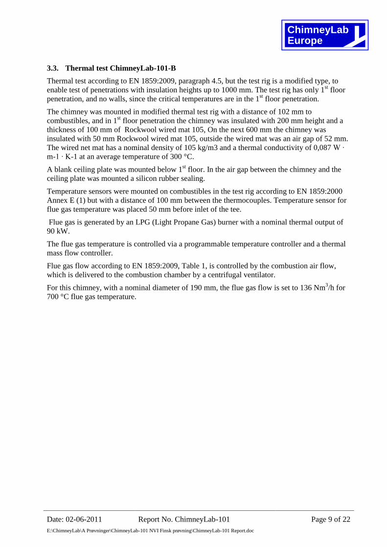
3.3. Thermal test ChimneyLab-101-B
Thermal test according to EN 1859:2009, paragraph 4.5, but the test rig is a modified type, to
enable test of penetrations with insulation heights up to 1000 mm. The test rig has only 1st floor
penetration, and no walls, since the critical temperatures are in the 1st floor penetration.
The chimney was mounted in modified thermal test rig with a distance of 102 mm to
combustibles, and in 1st floor penetration the chimney was insulated with 200 mm height and a
thickness of 100 mm of Rockwool wired mat 105, On the next 600 mm the chimney was
insulated with 50 mm Rockwool wired mat 105, outside the wired mat was an air gap of 52 mm.
The wired net mat has a nominal density of 105 kg/m3 and a thermal conductivity of 0,087 W ∙
m-1 ∙ K-1 at an average temperature of 300 °C.
A blank ceiling plate was mounted below 1st floor. In the air gap between the chimney and the
ceiling plate was mounted a silicon rubber sealing.
Temperature sensors were mounted on combustibles in the test rig according to EN 1859:2000
Annex E (1) but with a distance of 100 mm between the thermocouples. Temperature sensor for
flue gas temperature was placed 50 mm before inlet of the tee.
Flue gas is generated by an LPG (Light Propane Gas) burner with a nominal thermal output of
90 kW.
The flue gas temperature is controlled via a programmable temperature controller and a thermal
mass flow controller.
Flue gas flow according to EN 1859:2009, Table 1, is controlled by the combustion air flow,
which is delivered to the combustion chamber by a centrifugal ventilator.
For this chimney, with a nominal diameter of 190 mm, the flue gas flow is set to 136 Nm3/h for
700 °C flue gas temperature.
ChimneyLabEurope
Date: 02-06-2011 Report No. ChimneyLab-101 Page 10 of 22
E:\ChimneyLab\A Prøvninger\ChimneyLab-101 NVI Finsk prøvning\ChimneyLab-101 Report.doc
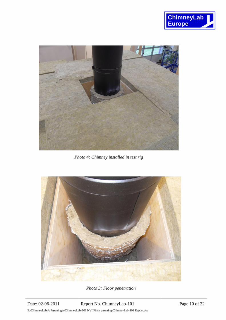
Photo 4: Chimney installed in test rig
Photo 3: Floor penetration
ChimneyLabEurope
Date: 02-06-2011 Report No. ChimneyLab-101 Page 11 of 22
E:\ChimneyLab\A Prøvninger\ChimneyLab-101 NVI Finsk prøvning\ChimneyLab-101 Report.doc
Side 1
TE 1.1-1.5
Position of thermocouples
A A
Joist 1st floor
80
0
980
10
0
23
00
Side 3
TE 3.1-3.5
Side 4
TE 4.1-4.5
Side 1
TE 1.1 to 1.5
A-A
Joist 1st floor
Side 2
TE 2.1 to 2.5
Side 3
TE 3.1 to 3.5Side 4
TE 4.1 to 4.5
Air gap 7,5 mm
520
324
556
315
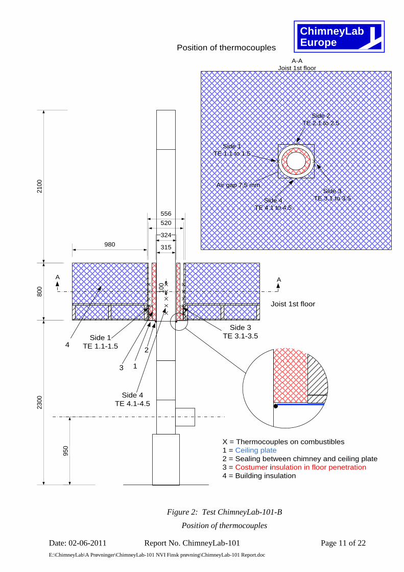
X = Thermocouples on combustibles
1 = Ceiling plate
2 = Sealing between chimney and ceiling plate
3 = Costumer insulation in floor penetration
4 = Building insulation
1
2
3
4
21
00
95
0
Figure 2: Test ChimneyLab-101-B
Position of thermocouples

ChimneyLabEurope
Date: 02-06-2011 Report No. ChimneyLab-101 Page 12 of 22
E:\ChimneyLab\A Prøvninger\ChimneyLab-101 NVI Finsk prøvning\ChimneyLab-101 Report.doc
The chimney was mounted and tested under the following conditions:
Test no. ChimneyLab-101-B
Temperature class T600
Pressure class N1
Soot fire test (1000 °C) No
Distance to walls in zone B, mm -
Shaft in zone B -
1st floor penetration:
Distance to combustibles, mm 102
Ceiling plate below floor penetration Yes
Air gap between lower ceiling plate and chimney, mm 0
Rubber gasket on lower ceiling plate Yes
Ceiling plate above floor penetration No
Air gap between upper ceiling plate and chimney, mm -
Rubber gasket on upper ceiling plate -
Insulation height in floor penetration, mm 800
Insulation type in floor penetration Rockwool wired mat/air gap
Table 4: Test conditions

ChimneyLabEurope
Date: 02-06-2011 Report No. ChimneyLab-101 Page 13 of 22
E:\ChimneyLab\A Prøvninger\ChimneyLab-101 NVI Finsk prøvning\ChimneyLab-101 Report.doc
The chimney was tested in the following order:
Test order Description EN 1859:2009
Paragraph
1 Installation of chimney in thermal test rig. 4.5.3
2 Heat stress test T600 1st time
700 °C until steady state
4.5.3.1
Table 5: Thermal test order
Chimney elements used for the test were weighted and measured before installation:
Element
No.
Description Color Total
weight
kg
1 Tee Black 12,44
2 0,55 m section Black 9,21
3 0,55 m section Black 9,30
4 1,2 m section Black 18,64
5 1,2 m section Black 19,09
6 0,55 m section Black 9,01
Table 6: Chimney elements used in the test

ChimneyLabEurope
Date: 02-06-2011 Report No. ChimneyLab-101 Page 14 of 22
E:\ChimneyLab\A Prøvninger\ChimneyLab-101 NVI Finsk prøvning\ChimneyLab-101 Report.doc
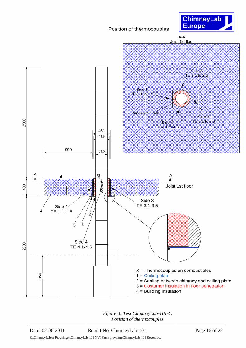
3.4. Thermal test ChimneyLab-101-C
Thermal test according to EN 1859:2009, paragraph 4.5, but the test rig is a modified type, to
enable test of penetrations with insulation heights up to 1000 mm. The test rig has only 1st floor
penetration, and no walls, since the critical temperatures are in the 1st floor penetration.
The chimney was mounted in modified thermal test rig with a distance of 50 mm to
combustibles, and in 1st floor penetration the chimney was insulated with 400 mm height and a
thickness of 50 mm of Rockwool wired mat 105.
The wired net mat has a nominal density of 105 kg/m3 and a thermal conductivity of 0,087 W ∙
m-1 ∙ K-1 at an average temperature of 300 °C
A blank ceiling plate was mounted below 1st floor. In the air gap between the chimney and the
ceiling plate was mounted a silicon rubber sealing.
Temperature sensors were mounted on combustibles in the test rig according to EN 1859:2000
Annex E (1) with a distance of 50 mm between the thermocouples. Temperature sensor for flue
gas temperature was placed 50 mm before inlet of the tee.
Flue gas is generated by an LPG (Light Propane Gas) burner with a nominal thermal output of
90 kW.
The flue gas temperature is controlled via a programmable temperature controller and a thermal
mass flow controller.
Flue gas flow according to EN 1859:2009, Table 1, is controlled by the combustion air flow,
which is delivered to the combustion chamber by a centrifugal ventilator.
For this chimney, with a nominal diameter of 190 mm, the flue gas flow is set to 134 Nm3/h for
550 °C flue gas temperature.
ChimneyLabEurope
Date: 02-06-2011 Report No. ChimneyLab-101 Page 15 of 22
E:\ChimneyLab\A Prøvninger\ChimneyLab-101 NVI Finsk prøvning\ChimneyLab-101 Report.doc
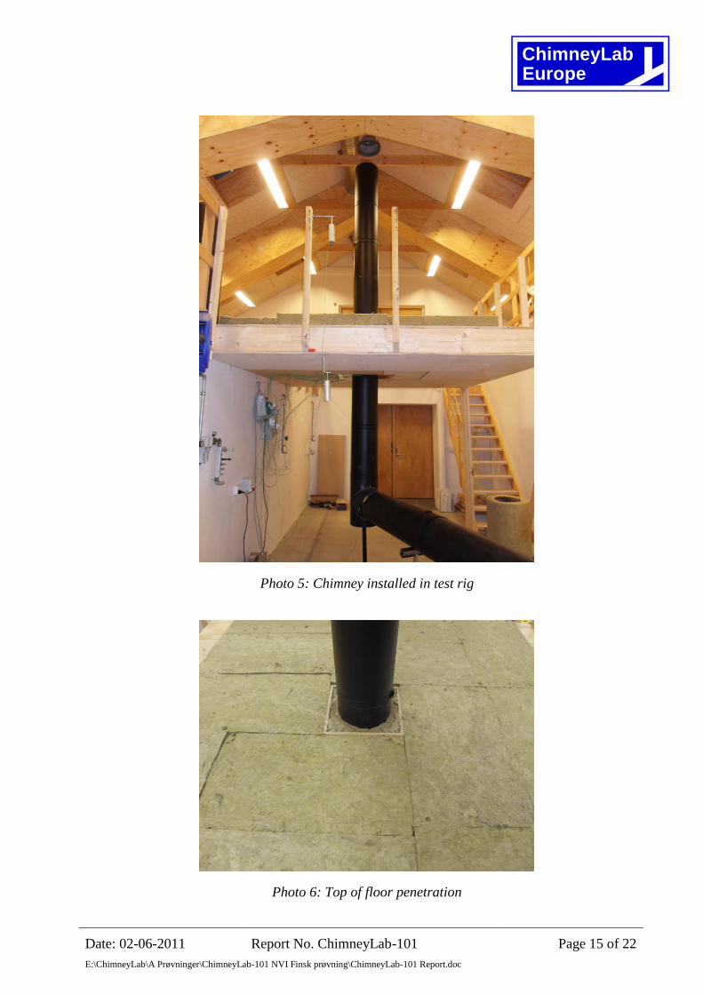
Photo 5: Chimney installed in test rig
Photo 6: Top of floor penetration
ChimneyLabEurope
Date: 02-06-2011 Report No. ChimneyLab-101 Page 16 of 22
E:\ChimneyLab\A Prøvninger\ChimneyLab-101 NVI Finsk prøvning\ChimneyLab-101 Report.doc
Side 1
TE 1.1-1.5
Position of thermocouples
Joist 1st floor
40
0
990
50
23
00
Side 3
TE 3.1-3.5
Side 4
TE 4.1-4.5
Side 1
TE 1.1 to 1.5
A-A
Joist 1st floor
Side 2
TE 2.1 to 2.5
Side 3
TE 3.1 to 3.5Side 4
TE 4.1 to 4.5
Air gap 7,5 mm
415
451
315
X = Thermocouples on combustibles
1 = Ceiling plate
2 = Sealing between chimney and ceiling plate
3 = Costumer insulation in floor penetration
4 = Building insulation
1
2
3
4
25
00
95
0
A A
Figure 3: Test ChimneyLab-101-C
Position of thermocouples
ChimneyLabEurope
Date: 02-06-2011 Report No. ChimneyLab-101 Page 17 of 22
E:\ChimneyLab\A Prøvninger\ChimneyLab-101 NVI Finsk prøvning\ChimneyLab-101 Report.doc
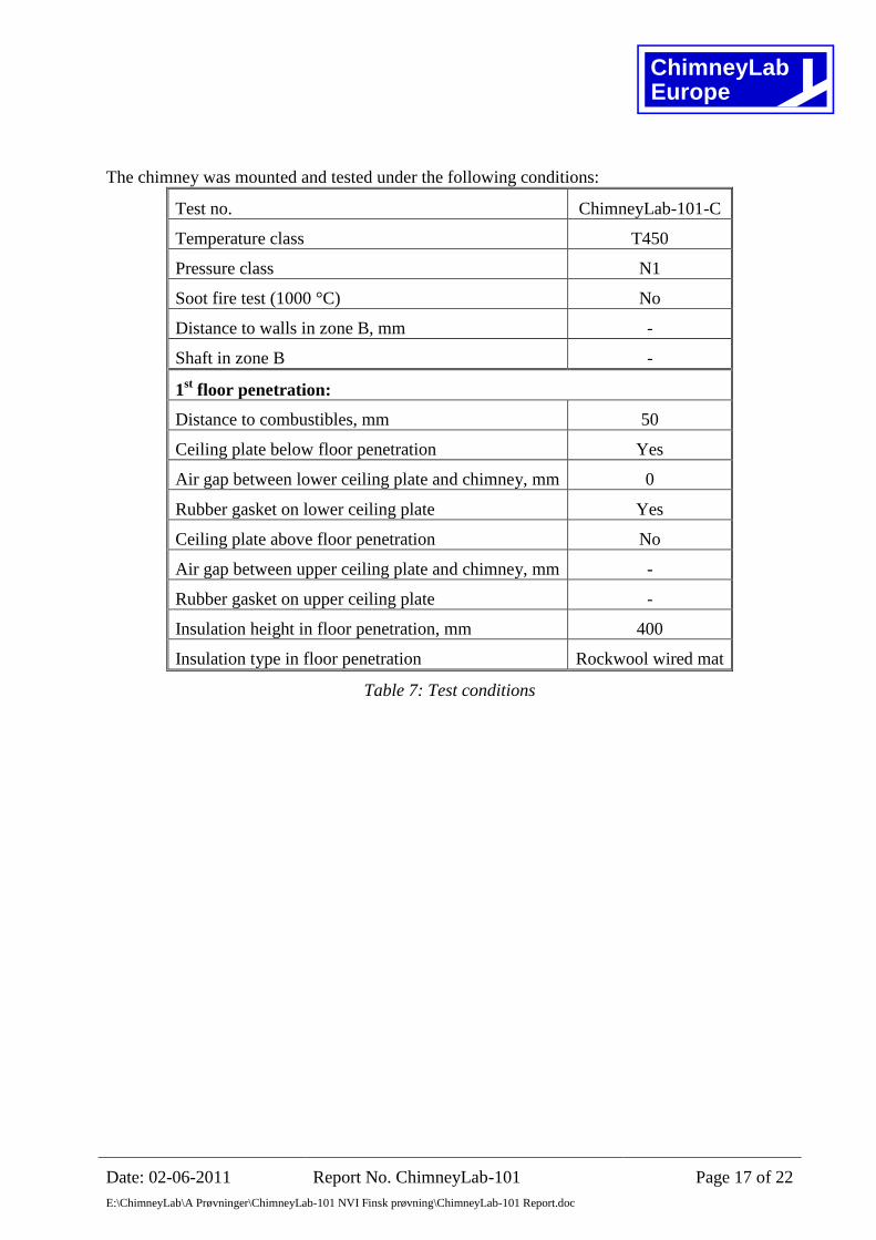
The chimney was mounted and tested under the following conditions:
Test no. ChimneyLab-101-C
Temperature class T450
Pressure class N1
Soot fire test (1000 °C) No
Distance to walls in zone B, mm -
Shaft in zone B -
1st floor penetration:
Distance to combustibles, mm 50
Ceiling plate below floor penetration Yes
Air gap between lower ceiling plate and chimney, mm 0
Rubber gasket on lower ceiling plate Yes
Ceiling plate above floor penetration No
Air gap between upper ceiling plate and chimney, mm -
Rubber gasket on upper ceiling plate -
Insulation height in floor penetration, mm 400
Insulation type in floor penetration Rockwool wired mat
Table 7: Test conditions
ChimneyLabEurope
Date: 02-06-2011 Report No. ChimneyLab-101 Page 18 of 22
E:\ChimneyLab\A Prøvninger\ChimneyLab-101 NVI Finsk prøvning\ChimneyLab-101 Report.doc
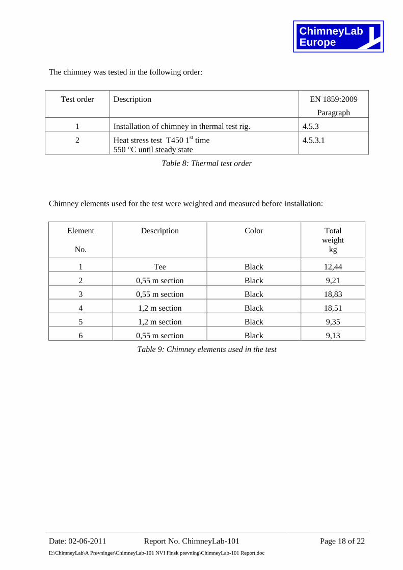
The chimney was tested in the following order:
Test order Description EN 1859:2009
Paragraph
1 Installation of chimney in thermal test rig. 4.5.3
2 Heat stress test T450 1st time
550 °C until steady state
4.5.3.1
Table 8: Thermal test order
Chimney elements used for the test were weighted and measured before installation:
Element
No.
Description Color Total
weight
kg
1 Tee Black 12,44
2 0,55 m section Black 9,21
3 0,55 m section Black 18,83
4 1,2 m section Black 18,51
5 1,2 m section Black 9,35
6 0,55 m section Black 9,13
Table 9: Chimney elements used in the test
ChimneyLabEurope
Date: 02-06-2011 Report No. ChimneyLab-101 Page 19 of 22
E:\ChimneyLab\A Prøvninger\ChimneyLab-101 NVI Finsk prøvning\ChimneyLab-101 Report.doc
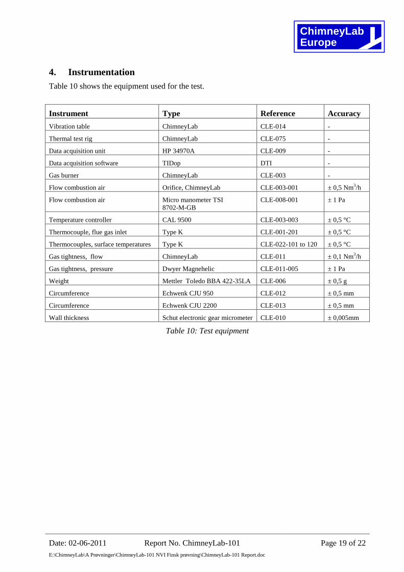
4. Instrumentation
Table 10 shows the equipment used for the test.
Instrument Type Reference Accuracy
Vibration table ChimneyLab CLE-014 -
Thermal test rig ChimneyLab CLE-075 -
Data acquisition unit HP 34970A CLE-009 -
Data acquisition software TIDop DTI -
Gas burner ChimneyLab CLE-003 -
Flow combustion air Orifice, ChimneyLab CLE-003-001 ± 0,5 Nm3/h
Flow combustion air Micro manometer TSI
8702-M-GB
CLE-008-001 ± 1 Pa
Temperature controller CAL 9500 CLE-003-003 ± 0,5 °C
Thermocouple, flue gas inlet Type K CLE-001-201 ± 0,5 °C
Thermocouples, surface temperatures Type K CLE-022-101 to 120 ± 0,5 °C
Gas tightness, flow ChimneyLab CLE-011 ± 0,1 Nm3/h
Gas tightness, pressure Dwyer Magnehelic CLE-011-005 ± 1 Pa
Weight Mettler Toledo BBA 422-35LA CLE-006 ± 0,5 g
Circumference Echwenk CJU 950 CLE-012 ± 0,5 mm
Circumference Echwenk CJU 2200 CLE-013 ± 0,5 mm
Wall thickness Schut electronic gear micrometer CLE-010 ± 0,005mm
Table 10: Test equipment
ChimneyLabEurope
Date: 02-06-2011 Report No. ChimneyLab-101 Page 20 of 22
E:\ChimneyLab\A Prøvninger\ChimneyLab-101 NVI Finsk prøvning\ChimneyLab-101 Report.doc
5. Test results
5.1. Gas tightness test
The chimney is classified as pressure type N1. As the chimney is already CE-marked, no gas
tightness tests are performed.
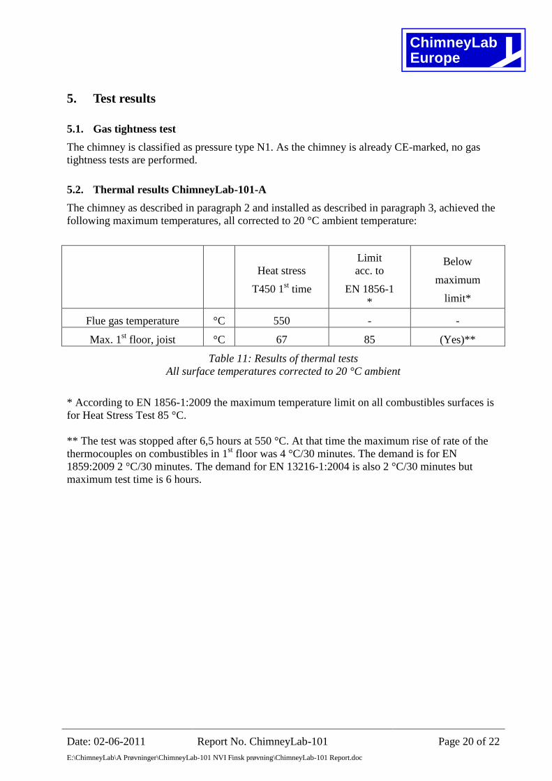
5.2. Thermal results ChimneyLab-101-A
The chimney as described in paragraph 2 and installed as described in paragraph 3, achieved the
following maximum temperatures, all corrected to 20 °C ambient temperature:
Heat stress
T450 1st time
Limit
acc. to
EN 1856-1
*
Below
maximum
limit*
Flue gas temperature °C 550 - -
Max. 1st floor, joist °C 67 85 (Yes)**
Table 11: Results of thermal tests
All surface temperatures corrected to 20 °C ambient
* According to EN 1856-1:2009 the maximum temperature limit on all combustibles surfaces is
for Heat Stress Test 85 °C.
** The test was stopped after 6,5 hours at 550 °C. At that time the maximum rise of rate of the
thermocouples on combustibles in 1st floor was 4 °C/30 minutes. The demand is for EN
1859:2009 2 °C/30 minutes. The demand for EN 13216-1:2004 is also 2 °C/30 minutes but
maximum test time is 6 hours.
ChimneyLabEurope
Date: 02-06-2011 Report No. ChimneyLab-101 Page 21 of 22
E:\ChimneyLab\A Prøvninger\ChimneyLab-101 NVI Finsk prøvning\ChimneyLab-101 Report.doc
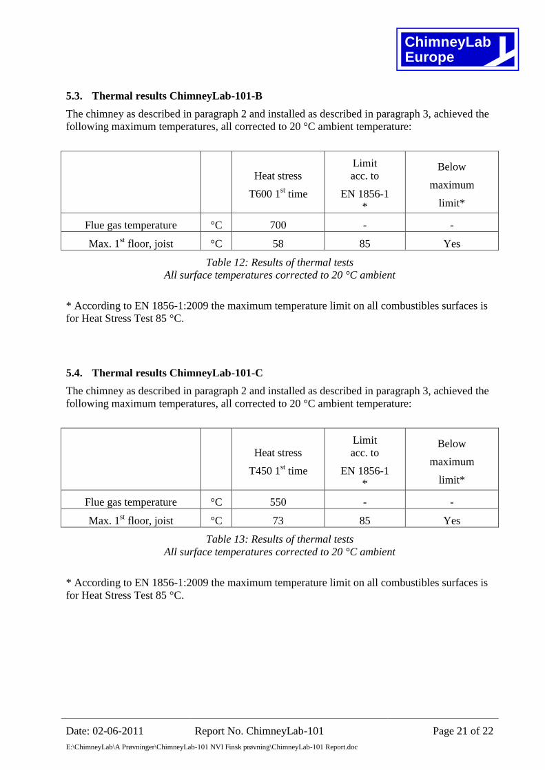
5.3. Thermal results ChimneyLab-101-B
The chimney as described in paragraph 2 and installed as described in paragraph 3, achieved the
following maximum temperatures, all corrected to 20 °C ambient temperature:
Heat stress
T600 1st time
Limit
acc. to
EN 1856-1
*
Below
maximum
limit*
Flue gas temperature °C 700 - -
Max. 1st floor, joist °C 58 85 Yes
Table 12: Results of thermal tests
All surface temperatures corrected to 20 °C ambient
* According to EN 1856-1:2009 the maximum temperature limit on all combustibles surfaces is
for Heat Stress Test 85 °C.
5.4. Thermal results ChimneyLab-101-C
The chimney as described in paragraph 2 and installed as described in paragraph 3, achieved the
following maximum temperatures, all corrected to 20 °C ambient temperature:
Heat stress
T450 1st time
Limit
acc. to
EN 1856-1
*
Below
maximum
limit*
Flue gas temperature °C 550 - -
Max. 1st floor, joist °C 73 85 Yes
Table 13: Results of thermal tests
All surface temperatures corrected to 20 °C ambient
* According to EN 1856-1:2009 the maximum temperature limit on all combustibles surfaces is
for Heat Stress Test 85 °C.
ChimneyLabEurope
Date: 02-06-2011 Report No. ChimneyLab-101 Page 22 of 22
E:\ChimneyLab\A Prøvninger\ChimneyLab-101 NVI Finsk prøvning\ChimneyLab-101 Report.doc
6. Conclusion
The chimney, tested under the conditions described in chapter 3, meets the requirements in EN
1856-1:2009 regarding:
Combustibles surface temperatures during 1st heat stress test
However test ChimneyLab-101-A was stopped after 6,5 hours without having reached
steady state.
7. Remarks
All information from the manufacturer regarding materials used for the chimney has been
assumed by ChimneyLab Europe ApS. The materials have not been subject to any qualitative
tests, except from an immediate visual evaluation.
This report is not an approval, but the result of a test. Producer/importing company are obligated
to ensure that all relevant regulations during sale and installation of the chimney are fulfilled.
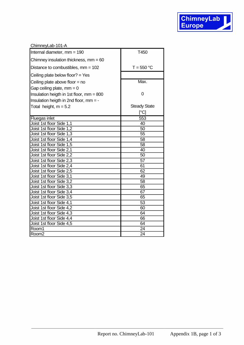
Report no. ChimneyLab-101 Appendix 1B, page 1 of 3
ChimneyLab-101-A
Internal diameter, mm = 190 T450
Chimney insulation thickness, mm = 60
Distance to combustibles, mm = 102 T = 550 °C
Ceiling plate below floor? = Yes
Ceiling plate above floor = no Max.
Gap ceiling plate, mm = 0
Insulation heigth in 1st floor, mm = 800 0
Insulation heigth in 2nd floor, mm = -
Total height, m = 5.2 Steady State
[°C]
Fluegas inlet 553Joist 1st floor Side 1,1 40Joist 1st floor Side 1,2 50Joist 1st floor Side 1,3 55
Joist 1st floor Side 1,4 58Joist 1st floor Side 1,5 58Joist 1st floor Side 2,1 40Joist 1st floor Side 2,2 50
Joist 1st floor Side 2,3 57Joist 1st floor Side 2,4 61Joist 1st floor Side 2,5 62Joist 1st floor Side 3,1 49Joist 1st floor Side 3,2 58Joist 1st floor Side 3,3 65Joist 1st floor Side 3,4 67Joist 1st floor Side 3,5 65
Joist 1st floor Side 4,1 53Joist 1st floor Side 4,2 60Joist 1st floor Side 4,3 64Joist 1st floor Side 4,4 66Joist 1st floor Side 4,5 64Room1 24Room2 24
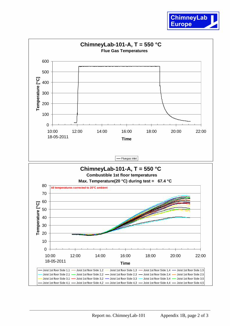
Report no. ChimneyLab-101 Appendix 1B, page 2 of 3
ChimneyLab-101-A, T = 550 °C
0
100
200
300
400
500
600
10:00 12:00 14:00 16:00 18:00 20:00 22:00
Time
Tem
pera
ture
[°C
]
Fluegas inlet
18-05-2011
Flue Gas Temperatures
ChimneyLab-101-A, T = 550 °C
0
10
20
30
40
50
60
70
80
10:00 12:00 14:00 16:00 18:00 20:00 22:00
Time
Tem
pera
ture
[°C
]
Joist 1st floor Side 1,1 Joist 1st floor Side 1,2 Joist 1st floor Side 1,3 Joist 1st floor Side 1,4 Joist 1st floor Side 1,5
Joist 1st floor Side 2,1 Joist 1st floor Side 2,2 Joist 1st floor Side 2,3 Joist 1st floor Side 2,4 Joist 1st floor Side 2,5
Joist 1st floor Side 3,1 Joist 1st floor Side 3,2 Joist 1st floor Side 3,3 Joist 1st floor Side 3,4 Joist 1st floor Side 3,5
Joist 1st floor Side 4,1 Joist 1st floor Side 4,2 Joist 1st floor Side 4,3 Joist 1st floor Side 4,4 Joist 1st floor Side 4,5
18-05-2011
Combustible 1st floor temperatures
Max. Temperature(20 °C) during test = 67.4 °C
All temperatures corrected to 20°C ambient
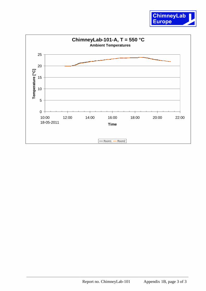
Report no. ChimneyLab-101 Appendix 1B, page 3 of 3
ChimneyLab-101-A, T = 550 °C
0
5
10
15
20
25
10:00 12:00 14:00 16:00 18:00 20:00 22:00
Time
Tem
pera
ture
[°C
]
Room1 Room2
18-05-2011
Ambient Temperatures
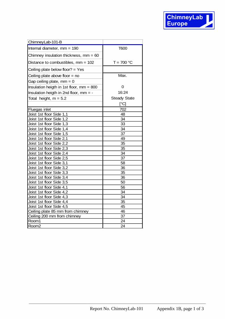
Report No. ChimneyLab-101 Appendix 1B, page 1 of 3
ChimneyLab-101-B
Internal diameter, mm = 190 T600
Chimney insulation thickness, mm = 60
Distance to combustibles, mm = 102 T = 700 °C
Ceiling plate below floor? = Yes
Ceiling plate above floor = no Max.
Gap ceiling plate, mm = 0
Insulation heigth in 1st floor, mm = 800 0
Insulation heigth in 2nd floor, mm = - 16:24
Total height, m = 5.2 Steady State
[°C]
Fluegas inlet 702
Joist 1st floor Side 1,1 48
Joist 1st floor Side 1,2 34
Joist 1st floor Side 1,3 33
Joist 1st floor Side 1,4 34
Joist 1st floor Side 1,5 37
Joist 1st floor Side 2,1 49
Joist 1st floor Side 2,2 35
Joist 1st floor Side 2,3 35
Joist 1st floor Side 2,4 34
Joist 1st floor Side 2,5 37
Joist 1st floor Side 3,1 58
Joist 1st floor Side 3,2 36
Joist 1st floor Side 3,3 35
Joist 1st floor Side 3,4 36
Joist 1st floor Side 3,5 50
Joist 1st floor Side 4,1 56
Joist 1st floor Side 4,2 34
Joist 1st floor Side 4,3 34
Joist 1st floor Side 4,4 35
Joist 1st floor Side 4,5 45
Ceiling plate 85 mm from chimney 46
Ceiling 200 mm from chimney 37
Room1 24
Room2 24
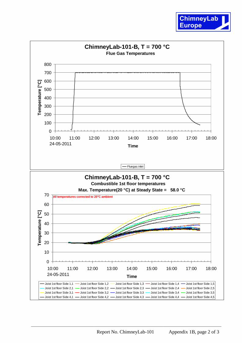
Report No. ChimneyLab-101 Appendix 1B, page 2 of 3
ChimneyLab-101-B, T = 700 °C
0
100
200
300
400
500
600
700
800
10:00 11:00 12:00 13:00 14:00 15:00 16:00 17:00 18:00
Time
Tem
pera
ture
[°C
]
Fluegas inlet
24-05-2011
Flue Gas Temperatures
ChimneyLab-101-B, T = 700 °C
0
10
20
30
40
50
60
70
10:00 11:00 12:00 13:00 14:00 15:00 16:00 17:00 18:00
Time
Tem
pera
ture
[°C
]
Joist 1st floor Side 1,1 Joist 1st floor Side 1,2 Joist 1st floor Side 1,3 Joist 1st floor Side 1,4 Joist 1st floor Side 1,5
Joist 1st floor Side 2,1 Joist 1st floor Side 2,2 Joist 1st floor Side 2,3 Joist 1st floor Side 2,4 Joist 1st floor Side 2,5
Joist 1st floor Side 3,1 Joist 1st floor Side 3,2 Joist 1st floor Side 3,3 Joist 1st floor Side 3,4 Joist 1st floor Side 3,5
Joist 1st floor Side 4,1 Joist 1st floor Side 4,2 Joist 1st floor Side 4,3 Joist 1st floor Side 4,4 Joist 1st floor Side 4,5
24-05-2011
Combustible 1st floor temperatures
Max. Temperature(20 °C) at Steady State = 58.0 °C
All temperatures corrected to 20°C ambient
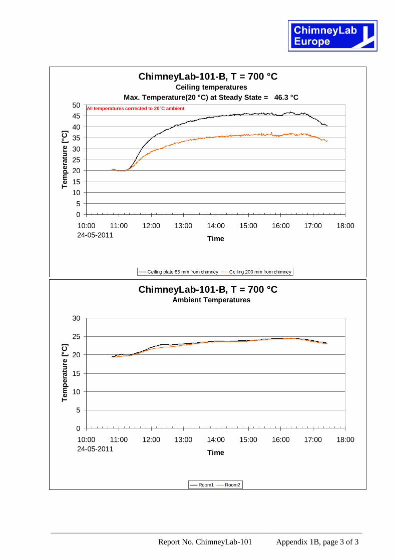
Report No. ChimneyLab-101 Appendix 1B, page 3 of 3
ChimneyLab-101-B, T = 700 °C
0
5
10
15
20
25
30
35
40
45
50
10:00 11:00 12:00 13:00 14:00 15:00 16:00 17:00 18:00
Time
Tem
pera
ture
[°C
]
Ceiling plate 85 mm from chimney Ceiling 200 mm from chimney
24-05-2011
Ceiling temperatures
Max. Temperature(20 °C) at Steady State = 46.3 °C
All temperatures corrected to 20°C ambient
ChimneyLab-101-B, T = 700 °C
0
5
10
15
20
25
30
10:00 11:00 12:00 13:00 14:00 15:00 16:00 17:00 18:00
Time
Tem
pera
ture
[°C
]
Room1 Room2
24-05-2011
Ambient Temperatures
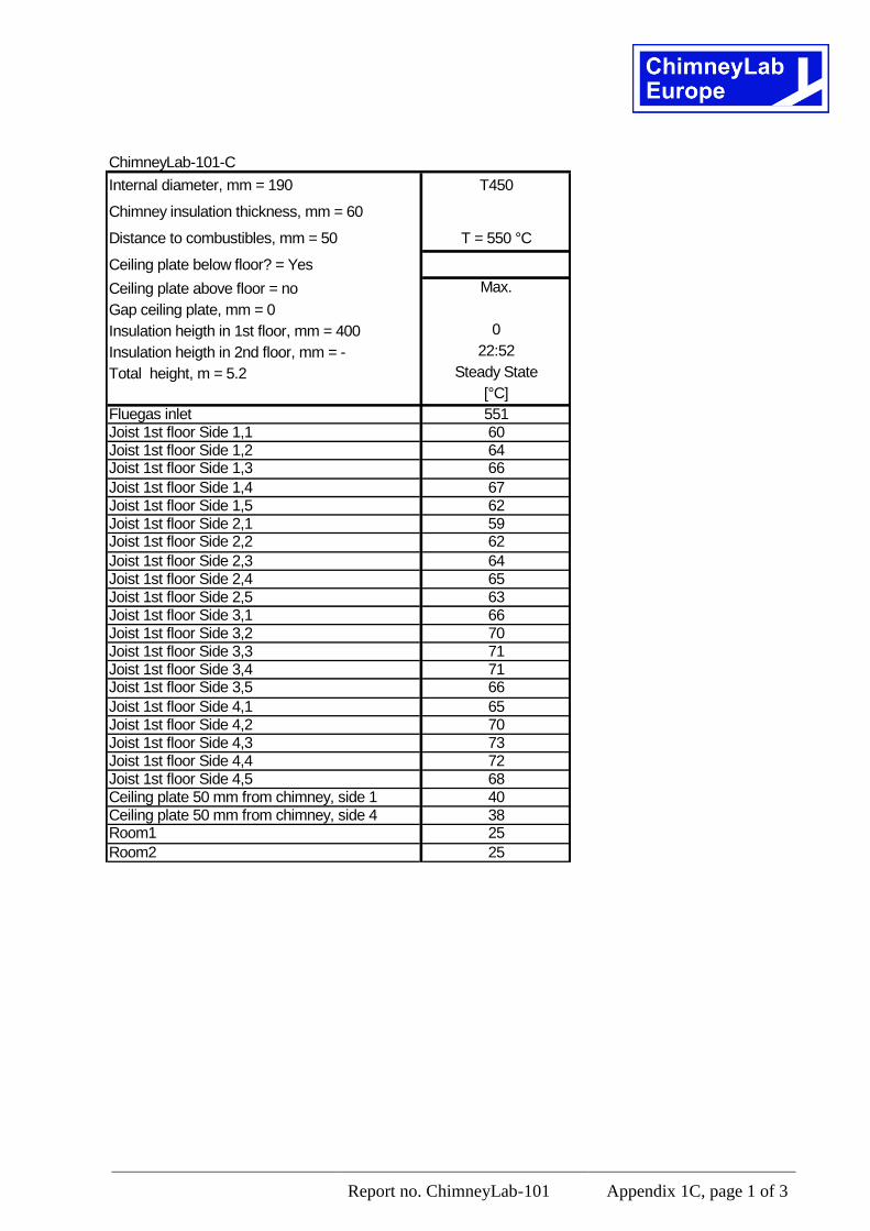
Report no. ChimneyLab-101 Appendix 1C, page 1 of 3
ChimneyLab-101-C
Internal diameter, mm = 190 T450
Chimney insulation thickness, mm = 60
Distance to combustibles, mm = 50 T = 550 °C
Ceiling plate below floor? = Yes
Ceiling plate above floor = no Max.
Gap ceiling plate, mm = 0
Insulation heigth in 1st floor, mm = 400 0
Insulation heigth in 2nd floor, mm = - 22:52
Total height, m = 5.2 Steady State
[°C]
Fluegas inlet 551Joist 1st floor Side 1,1 60Joist 1st floor Side 1,2 64Joist 1st floor Side 1,3 66
Joist 1st floor Side 1,4 67Joist 1st floor Side 1,5 62Joist 1st floor Side 2,1 59Joist 1st floor Side 2,2 62
Joist 1st floor Side 2,3 64Joist 1st floor Side 2,4 65Joist 1st floor Side 2,5 63Joist 1st floor Side 3,1 66Joist 1st floor Side 3,2 70Joist 1st floor Side 3,3 71Joist 1st floor Side 3,4 71Joist 1st floor Side 3,5 66
Joist 1st floor Side 4,1 65Joist 1st floor Side 4,2 70Joist 1st floor Side 4,3 73Joist 1st floor Side 4,4 72Joist 1st floor Side 4,5 68Ceiling plate 50 mm from chimney, side 1 40Ceiling plate 50 mm from chimney, side 4 38Room1 25
Room2 25
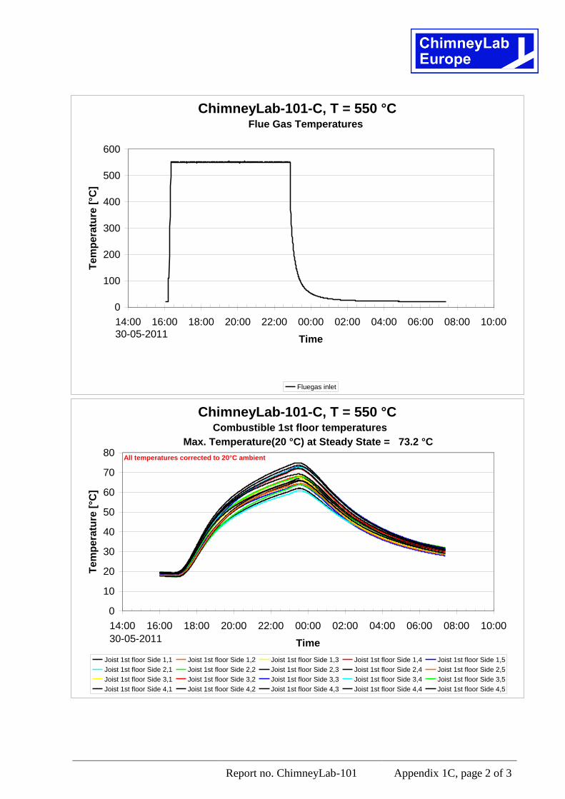
Report no. ChimneyLab-101 Appendix 1C, page 2 of 3
ChimneyLab-101-C, T = 550 °C
0
100
200
300
400
500
600
14:00 16:00 18:00 20:00 22:00 00:00 02:00 04:00 06:00 08:00 10:00
Time
Te
mp
era
ture
[°C
]
Fluegas inlet
30-05-2011
Flue Gas Temperatures
ChimneyLab-101-C, T = 550 °C
0
10
20
30
40
50
60
70
80
14:00 16:00 18:00 20:00 22:00 00:00 02:00 04:00 06:00 08:00 10:00
Time
Te
mp
era
ture
[°C
]
Joist 1st floor Side 1,1 Joist 1st floor Side 1,2 Joist 1st floor Side 1,3 Joist 1st floor Side 1,4 Joist 1st floor Side 1,5
Joist 1st floor Side 2,1 Joist 1st floor Side 2,2 Joist 1st floor Side 2,3 Joist 1st floor Side 2,4 Joist 1st floor Side 2,5
Joist 1st floor Side 3,1 Joist 1st floor Side 3,2 Joist 1st floor Side 3,3 Joist 1st floor Side 3,4 Joist 1st floor Side 3,5
Joist 1st floor Side 4,1 Joist 1st floor Side 4,2 Joist 1st floor Side 4,3 Joist 1st floor Side 4,4 Joist 1st floor Side 4,5
30-05-2011
Combustible 1st floor temperatures
Max. Temperature(20 °C) at Steady State = 73.2 °C
All temperatures corrected to 20°C ambient
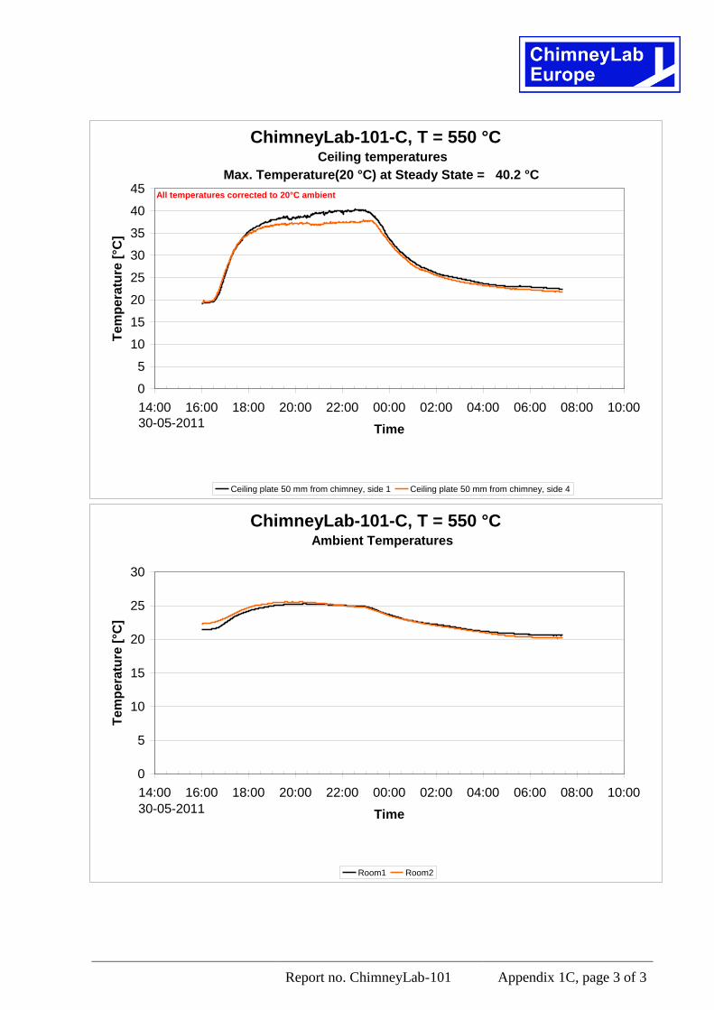
Report no. ChimneyLab-101 Appendix 1C, page 3 of 3
ChimneyLab-101-C, T = 550 °C
0
5
10
15
20
25
30
35
40
45
14:00 16:00 18:00 20:00 22:00 00:00 02:00 04:00 06:00 08:00 10:00
Time
Te
mp
era
ture
[°C
]
Ceiling plate 50 mm from chimney, side 1 Ceiling plate 50 mm from chimney, side 4
30-05-2011
Ceiling temperatures
Max. Temperature(20 °C) at Steady State = 40.2 °C
All temperatures corrected to 20°C ambient
ChimneyLab-101-C, T = 550 °C
0
5
10
15
20
25
30
14:00 16:00 18:00 20:00 22:00 00:00 02:00 04:00 06:00 08:00 10:00
Time
Te
mp
era
ture
[°C
]
Room1 Room2
30-05-2011
Ambient Temperatures
Mer info på www.paroc.se
PRODUKTER ■
11
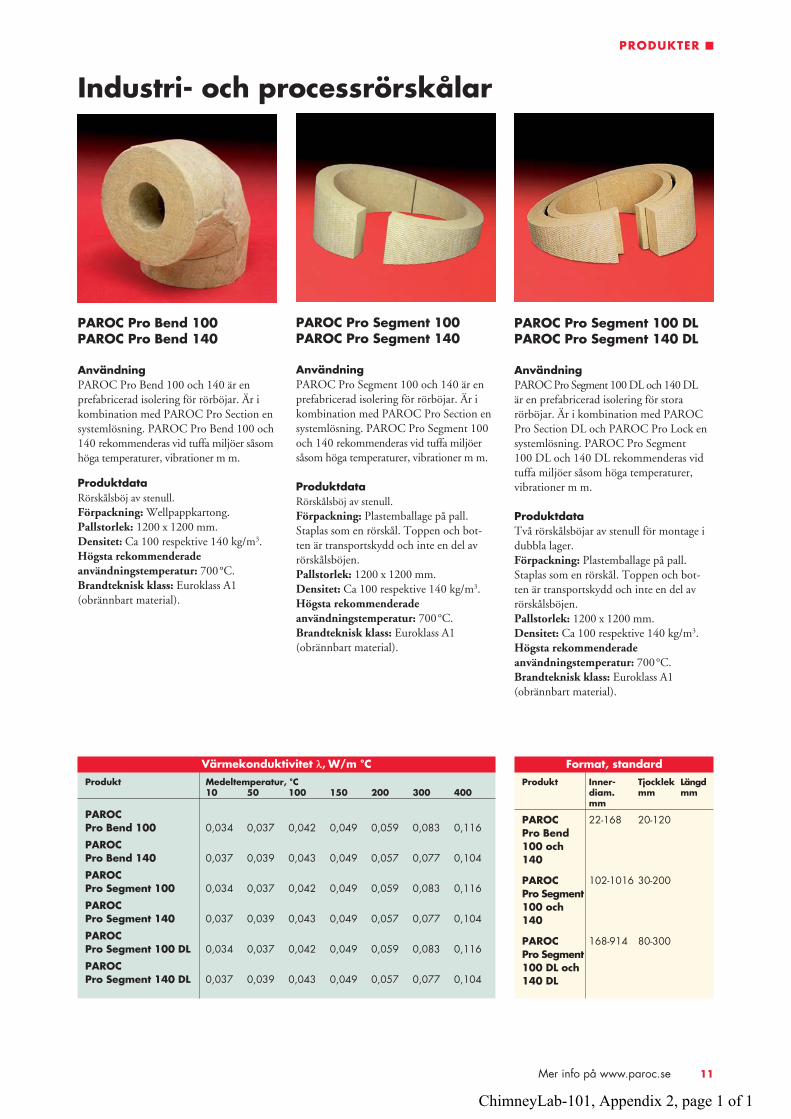
Industri- och processrörskålar
PAROC Pro Bend 100 PAROC Pro Bend 140
AnvändningPAROC Pro Bend 100 och 140 är en prefabricerad isolering för rörböjar. Är i kombination med PAROC Pro Section en systemlösning. PAROC Pro Bend 100 och 140 rekommenderas vid tuffa miljöer såsom höga temperaturer, vibrationer m m.
ProduktdataRörskålsböj av stenull.Förpackning: Wellpappkartong.Pallstorlek: 1200 x 1200 mm.Densitet: Ca 100 respektive 140 kg/m3.Högsta rekommenderade användningstemperatur: 700°C. Brandteknisk klass: Euroklass A1 (obrännbart material).
Värmekonduktivitet λ, W/m °CProdukt Medeltemperatur, °C 10 50 100 150 200 300 400
PAROCPro Bend 100 0,034 0,037 0,042 0,049 0,059 0,083 0,116
PAROCPro Bend 140 0,037 0,039 0,043 0,049 0,057 0,077 0,104
PAROCPro Segment 100 0,034 0,037 0,042 0,049 0,059 0,083 0,116
PAROCPro Segment 140 0,037 0,039 0,043 0,049 0,057 0,077 0,104
PAROCPro Segment 100 DL 0,034 0,037 0,042 0,049 0,059 0,083 0,116
PAROCPro Segment 140 DL 0,037 0,039 0,043 0,049 0,057 0,077 0,104
PAROC Pro Segment 100 PAROC Pro Segment 140
AnvändningPAROC Pro Segment 100 och 140 är en prefabricerad isolering för rörböjar. Är i kombination med PAROC Pro Section en systemlösning. PAROC Pro Segment 100 och 140 rekommenderas vid tuffa miljöer såsom höga temperaturer, vibrationer m m.
ProduktdataRörskålsböj av stenull.Förpackning: Plast emballage på pall. Staplas som en rörskål. Toppen och bot-ten är transportskydd och inte en del av rörskålsböjen.Pallstorlek: 1200 x 1200 mm.Densitet: Ca 100 respektive 140 kg/m3.Högsta rekommenderade användningstemperatur: 700°C. Brandteknisk klass: Euroklass A1 (obrännbart material).
PAROC Pro Segment 100 DL PAROC Pro Segment 140 DL
AnvändningPAROC Pro Segment 100 DL och 140 DL är en prefabricerad isolering för stora rörböjar. Är i kombination med PAROC Pro Section DL och PAROC Pro Lock en systemlösning. PAROC Pro Segment100 DL och 140 DL rekommenderas vid tuffa miljöer såsom höga temperaturer, vibrationer m m.
ProduktdataTvå rörskålsböjar av stenull för montage i dubbla lager.Förpackning: Plast emballage på pall. Staplas som en rörskål. Toppen och bot-ten är transportskydd och inte en del av rörskålsböjen.Pallstorlek: 1200 x 1200 mm.Densitet: Ca 100 respektive 140 kg/m3.Högsta rekommenderade användningstemperatur: 700°C. Brandteknisk klass: Euroklass A1 (obrännbart material).
Format, standardProdukt Inner- Tjocklek Längd diam. mm mm mm
PAROC 22-168 20-120 Pro Bend 100 och140
PAROC 102-1016 30-200 Pro Segment100 och140
PAROC 168-914 80-300 Pro Segment 100 DL och140 DL
ChimneyLab-101, Appendix 2, page 1 of 1
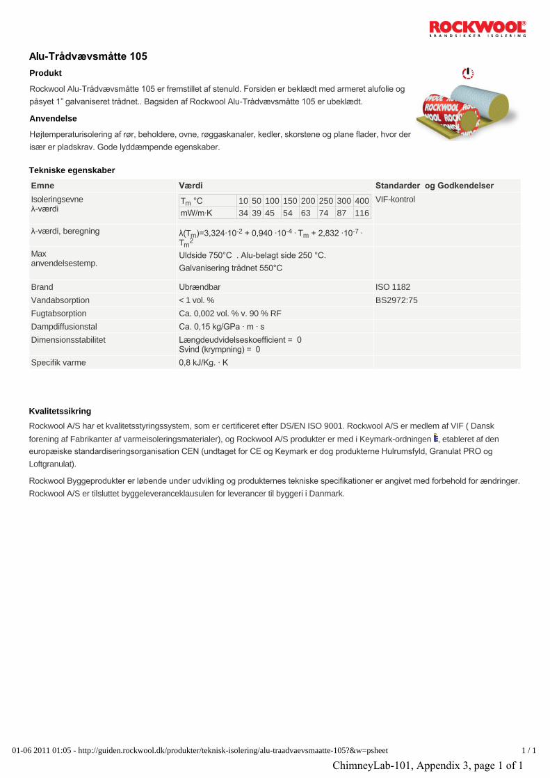
Alu-Trådvævsmåtte 105
Tekniske egenskaber
Kvalitetssikring
Produkt
Anvendelse
Rockwool Alu-Trådvævsmåtte 105 er fremstillet af stenuld. Forsiden er beklædt med armeret alufolie og
påsyet 1” galvaniseret trådnet.. Bagsiden af Rockwool Alu-Trådvævsmåtte 105 er ubeklædt.
Højtemperaturisolering af rør, beholdere, ovne, røggaskanaler, kedler, skorstene og plane flader, hvor der
især er pladskrav. Gode lyddæmpende egenskaber.
Emne Værdi Standarder og Godkendelser
Isoleringsevneλ-værdi
T °C 10 50 100 150 200 250 300 400
mW/m∙K 34 39 45 54 63 74 87 116
VIF-kontrol
λ-værdi, beregning λ(T )=3,324∙10 + 0,940 ∙10 ∙ T + 2,832 ∙10 ∙ T
Maxanvendelsestemp.
Uldside 750°C . Alu-belagt side 250 °C.
Galvanisering trådnet 550°C
Brand Ubrændbar ISO 1182
Vandabsorption < 1 vol. % BS2972:75
Fugtabsorption Ca. 0,002 vol. % v. 90 % RF
Dampdiffusionstal Ca. 0,15 kg/GPa ∙ m ∙ s
Dimensionsstabilitet Længdeudvidelseskoefficient = 0 Svind (krympning) = 0
Specifik varme 0,8 kJ/Kg. ∙ K
Rockwool A/S har et kvalitetsstyringssystem, som er certificeret efter DS/EN ISO 9001. Rockwool A/S er medlem af VIF ( Dansk
forening af Fabrikanter af varmeisoleringsmaterialer), og Rockwool A/S produkter er med i Keymark-ordningen , etableret af den
europæiske standardiseringsorganisation CEN (undtaget for CE og Keymark er dog produkterne Hulrumsfyld, Granulat PRO og
Loftgranulat).
Rockwool Byggeprodukter er løbende under udvikling og produkternes tekniske specifikationer er angivet med forbehold for ændringer.
Rockwool A/S er tilsluttet byggeleveranceklausulen for leverancer til byggeri i Danmark.
m
m-2 -4
m-7
m2
01-06 2011 01:05 - http://guiden.rockwool.dk/produkter/teknisk-isolering/alu-traadvaevsmaatte-105?&w=psheet 1 / 1
ChimneyLab-101, Appendix 3, page 1 of 1