Embed Size (px)
Citation preview
Measurement setup
¸RTO2044
UE
Antennaarray
RF/RRH
Meas. 3
Meas. 2
Meas. 1
Ref. 3
Base-band
Base station
Beamforming in the antenna diagram
0 °
Four antenna elements, correlated, copolarized, ½ wavelength separation, 90 ° shift per antenna element
+30 °
+60 °
+90 °
–60 °
–90 °
–30 °–3 dB
–20 dB
φ
Main lobe, Side lobe
Test
& M
easu
rem
ent
Appl
icat
ion
Card
| 01
.01
Test
ing
of L
TE b
eam
form
ing
Testing of LTE beamformingLTE is becoming the predominant wireless technology. Among several new features of this standard, the multiple input multiple output (MIMO) technology offers various advantages. It improves the throughput, extends the reach, reduces interference and improves the signal to interference plus noise ratio (SINR) with beamforming. LTE supports various modes in order to optimize the transmission settings. An LTE MIMO base station consists of a baseband unit, a remote radio head (RRH) and an array of up to eight antennas. The RRH upconverts the digital signals of the baseband unit into analog signals for each antenna.
Your taskIn the described scenario, the base station software con-trols the weighting of the individual antenna signals to pan the main beam lobe to the UE. These signals look intricate. The relationship of the weighting among the channels is a multiplication with a complex vector due to polarization. For software tests or system debugging, it is important to examine the signals and verify the weighting, which might be either predefined according to the standard, or adaptive to the position of the UE.
T&M solutionFor this task, the R&S®RTO2044 and the R&S®RTO1044 are powerful exploration tools for analyzing the magnitude and phase shift between antenna channels. Due to the high acquisition rate and the high-performance FFT, signal changes can be detected quickly and no downconversion is necessary. The bandwidth of the R&S®RTO covers the defined frequency bands.
Beamforming is typically used in LTE time division duplex mode (TDD), when the signal is not contiguous. For these signals, the R&S®RTO oscilloscopes have the trigger types width and window, which support capturing the down-stream pulse and prevent recording of pause times. This significantly simplifies spectral analysis. A further benefit is the multichannel capability of the R&S®RTO. It can easily be extended across several scopes if more than four chan-nels need to be analyzed in parallel.
RTO2044_ac_en_3607-5590-92_v0101.indd 1 12.08.2016 09:58:24
2
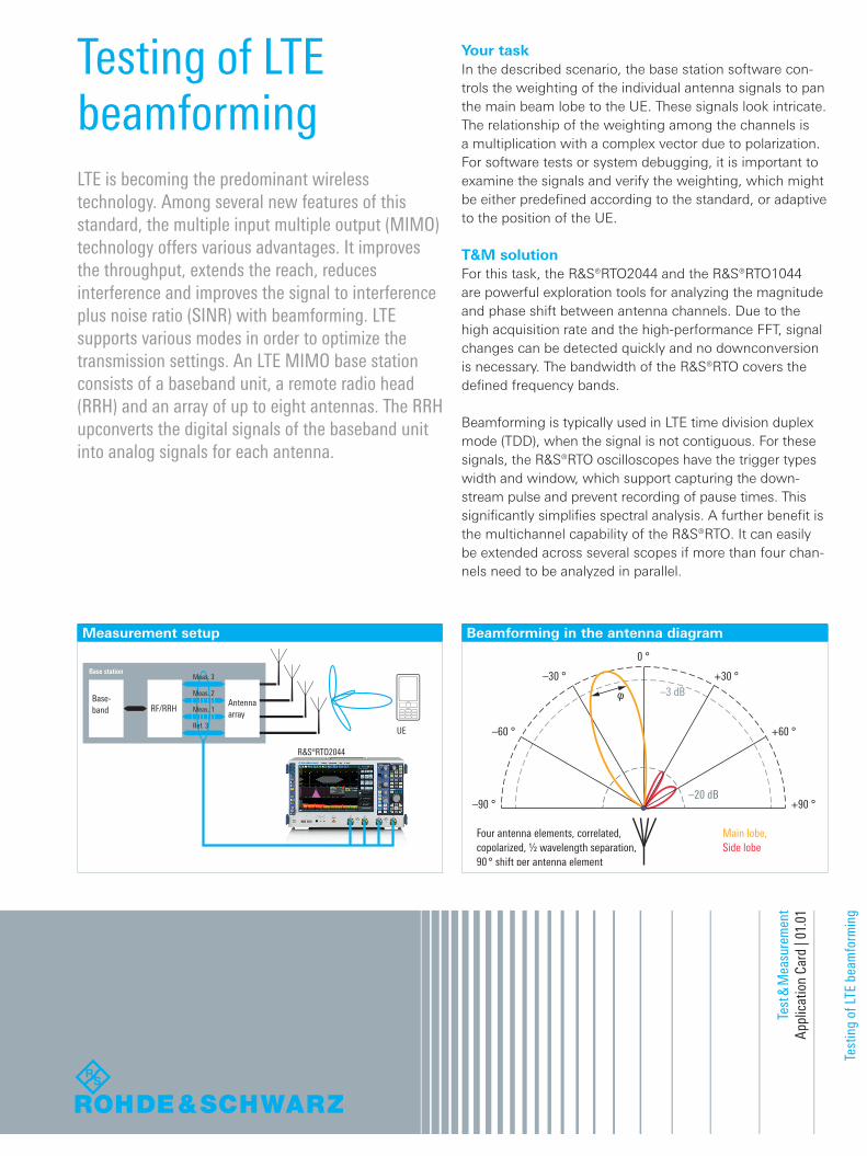
Signal powerTo check the spectral conformity of the signal, the spec-trum of the REF channel is displayed below, and as expect-ed it is a 15 MHz wide signal at 2.0175 GHz (LTE band). Weighting in terms of magnitude can be measured using the automated VRMS measurement function for the REF and MEAS channels. The ratio of RMS voltages between the REF and MEAS channels gives the magnitude of the weighting factor. Fig. 4 shows the RMS voltage measure-ment on the right, below are the traces of the REF (blue) and the MEAS (pink) channels. The measurement provides an accurate value since it is focused only on the signal. The trigger setup ensures that noise during a gap is ex-cluded from the measurement.
Phase shiftFor the phase shift between the REF and the MEAS chan-nels, a MATH channel is set up to calculate the phase dif-ference. The result is shown in Fig.5. Two things are notable: ❙ First, the occasional spikes on the waveform. These spikes are caused by non-symbol synchronous sampling. They can be reduced by locking the scope to the transmitter clock, setting the FFT resolution bandwidth (RBW) equal to the LTE subcarrier bandwidth of 15 kHz and adjusting the trigger position to the optimal point of 40 µs for this example. The improved phase difference is displayed in Fig. 6, which appears much smoother. The spectrum of the REF channel has also improved compared to Fig. 4
ApplicationIn the example measurement setup, the REF and the MEAS1 channels of an LTE transmitter were connected to an R&S®RTO, which corresponds to a 1×2 MIMO system.
Vertical and horizontal settingsIn a first measurement, the LTE transmitter asserts an LTE TDD signal and the oscilloscope acquires this signal using two channels with a vertical scale higher than 80 % of the full scale. The horizontal scale is set to achieve a compro-mise between a high acquisition rate and having enough samples for the FFT and a sufficient resolution bandwidth (RBW).
The width trigger of the R&S®RTO is used to capture only the bursts of an LTE TDD signal. The gaps inbetween the pulses are ignored and the FFT measurement of the signal is not biased by the noise of the gap sections.
Fig. 3 shows a stable graph of two LTE TDD bursts cap-tured with a width trigger of 1 ms and a large acquisition time of 20 ms. The trigger level is shown as a red dashed line.
Fig.3: Stable trigger of an LTE TDD signal.
Fig. 4: Spectrum and RMS measurement of the LTE TDD signal.
Fig. 5: Phase difference between the REF and MEAS channel. Fig. 6: Phase difference with optimized acquisition parameters.
RTO2044_ac_en_3607-5590-92_v0101.indd 2 12.08.2016 09:58:25
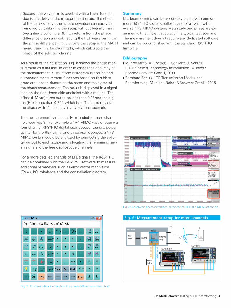
Fig. 9: Measurement setup for more channels
......
...
...
Antennaarray
Powersplitter
RF/RRH
MEAS n
MEAS
REF
Base-band
Base station
¸RTO2044¸RTO2044
MEA
S ch
anne
l
REF
chan
nel
UE
Rohde & Schwarz Testing of LTE beamforming 3
SummaryLTE beamforming can be accurately tested with one or more R&S®RTO digital oscilloscopes for a 1×2, 1×4 or even a 1×8 MIMO system. Magnitude and phase are ex-amined with sufficient accuracy in a typical test scenario. The measurement doesn’t require any dedicated software and can be accomplished with the standard R&S®RTO firmware.
Bibliography ❙ M. Kottkamp, A. Rössler, J. Schlienz, J. Schütz. LTE Release 9 Technology Introduction. Munich : Rohde & Schwarz GmbH, 2011
❙ Bernhard Schulz. LTE Transmission Modes and Beamforming. Munich : Rohde & Schwarz GmbH, 2015
❙ Second, the waveform is overlaid with a linear function due to the delay of the measurement setup. The effect of the delay or any other phase deviation can easily be removed by calibrating the setup without beamforming (weighting), building a REF waveform from the phase difference graph and subtracting the REF waveform from the phase difference. Fig. 7 shows the setup in the MATH menu using the function fftphi, which calculates the phase of the selected channel
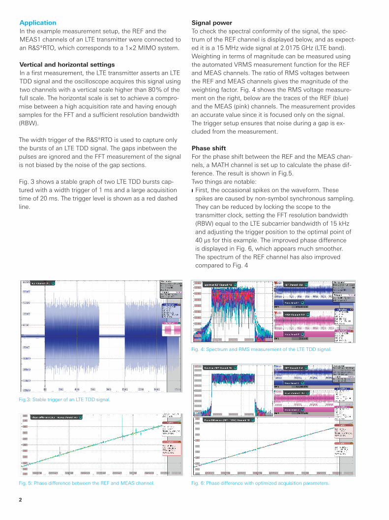
As a result of the calibration, Fig. 8 shows the phase mea-surement as a flat line. In order to assess the accuracy of the measurement, a waveform histogram is applied and automated measurement functions based on this histo-gram are used to determine the mean and the sigma of the phase measurement. The result is displayed in a signal icon on the right-hand side encircled with a red line. The offset (HMean) turns out to be less than 0.1° and the sig-ma (Hσ) is less than 0.25°, which is sufficient to measure the phase with 1° accuracy in a typical test scenario.
The measurement can be easily extended to more chan-nels (see Fig. 9). For example a 1×4 MIMO would require a four-channel R&S®RTO digital oscilloscope. Using a power splitter for the REF signal and three oscilloscopes, a 1×8 MIMO system could be analyzed by connecting the split-ter output to each scope and allocating the remaining sev-en signals to the free oscilloscope channels.
For a more detailed analysis of LTE signals, the R&S®RTO can be combined with the R&S®VSE software to measure additional parameters such as error vector magnitude (EVM), I/Q imbalance and the constellation diagram.
Fig. 8: Calibrated phase difference between the REF and MEAS channels.
Fig. 7: Formula editor to calculate the phase difference without bias.
RTO2044_ac_en_3607-5590-92_v0101.indd 3 12.08.2016 09:58:26
Service that adds value❙ Worldwide ❙ Local and personalized❙ Customized and flexible❙ Uncompromising quality ❙ Long-term dependability
R&S® is a registered trademark of Rohde & Schwarz GmbH & Co. KG
Trade names are trademarks of the owners
PD 3607.5590.92 | Version 01.01 | August 2016 (as)
Testing of LTE beamforming
Data without tolerance limits is not binding | Subject to change
© 2016 Rohde & Schwarz GmbH & Co. KG | 81671 Munich, Germany
About Rohde & SchwarzThe Rohde & Schwarz electronics group offers innova-tive solutions in the following business fields: test and measurement, broadcast and media, secure communica-tions, cybersecurity, radiomonitoring and radiolocation. Founded more than 80 years ago, the independent com-pany which is headquartered in Munich, Germany, has an extensive sales and service network with locations in more than 70 countries.
3607
.559
0.92
01.
01 P
DP
1 e
n
Regional contact ❙ Europe, Africa, Middle East | +49 89 4129 12345 [email protected]
❙ North America | 1 888 TEST RSA (1 888 837 87 72) [email protected]
❙ Latin America | +1 410 910 79 88 [email protected]
❙ Asia Pacific | +65 65 13 04 88 [email protected]
❙ China | +86 800 810 82 28 | +86 400 650 58 96 [email protected]
Rohde & Schwarz GmbH & Co. KGwww.rohde-schwarz.com
Rohde & Schwarz trainingwww.training.rohde-schwarz.com
Certified Environmental Management
ISO 14001Certified Quality Management
ISO 9001
Sustainable product design ❙ Environmental compatibility and eco-footprint ❙ Energy efficiency and low emissions ❙ Longevity and optimized total cost of ownership
3607559092
RTO2044_ac_en_3607-5590-92_v0101.indd 4 12.08.2016 09:58:26