Embed Size (px)
Citation preview

PO BOX 1200 305 Commerce Drive Winfield, Alabama 35594
TG-48-XB & TG-54-XBX ROTARY TILLER
OPERATOR MANUAL
Part No 999995 www.kingkutter.com


TO THE PURCHASER This manual contains valuable information about your new King Kutter XB or XBX Rotary Tiller. It has been carefully prepared to give you helpful suggestions for operating, ad-justing, servicing and ordering repair parts. Keep this manual in a convenient place for quick and easy reference. Study it carefully. You have purchased a de-pendable and sturdy tiller, but only by proper care and opera-tion can you expect to receive the service and long life de-signed and built into it. Sometime in the future your tiller may need new parts to replace those that are worn or broken. If so, go to your dealer and provide him with the model and part number.
Customer Information Name ______________________________________________ Purchased From ______________________________________ Date Purchased ______________________________________ Model No. ___________________________________________ Serial No. ___________________________________________
3

It is the purchaser and/or operator’s responsibility to…. l Read and understand the information contained in this
manual. l Operate, lubricate, assemble and maintain the
equipment in accordance with all instructions and safety procedures in this manual.
l Inspect the equipment and replace or repair any
parts that are damaged or worn which under contin-ued operation would cause damage, wear to other parts, or cause a safety hazard.
l Return the equipment or parts to the authorized
King Kutter dealer, from where it was purchased, for service or replacement of defective parts that are covered by warranty. (The King Kutter Factory may inspect equipment or parts before warranty claims are honored.)
l Payment of all costs incurred by the dealer for traveling
to or transporting the equipment for warranty inspection and or claims.
4

5
CONTENTS
ITEM PAGE Safety ......................................................................... 6 Assembly Instructions ................................................ 8 Before Putting Into Service ......................................... 8 Safety Training ......................................................... 11 Transportation Safety ............................................... 15 Attaching To Tractor ................................................. 16 Sizing PTO ............................................................... 18 Operating Instructions .............................................. 19 Maintenance ............................................................. 20 Maintenance Safety ................................................. 20 Safety Decal's And Locations ................................... 22 PTO Shaft Parts ....................................................... 27 Replacement Parts ................................................... 28 Side Gearbox Parts ................................................. 30 Top Gearbox Parts ............................................. …..32 Hub Parts………………………………………………...34 Warranty ………………………………………………...36

SAFETY READ AND FOLLOW THE INSTRUCTIONS IN THIS MANUAL AND ESPECIALLY IN THE SAFETY SECTION. FAILURE TO DO SO CAN RESULT IN SERIOUS INJURY OR DEATH. TAKE NOTE! THIS SAFETY ALERT SYMBOL FOUND THROUGHOUT THIS MANUAL IS USED TO CALL YOUR ATTENTION TO IN-STRUCTIONS INVOLVING YOUR PERSON-AL SAFETY AND THE SAFETY OF OTHERS. THIS SYMBOL MEANS
ATTENTION! BECOME ALERT!
YOUR SAFTEY IS INVOLVED
SIGNAL WORDS: The signal words DANGER, WARNING and CAUTION are used with the safety messages in this manual and with each safety signs. They are defined as follows: DANGER: Indicates an immediate hazardous situation that, if not avoided, could result in serious injury or death. This signal word is to be limited to the most ex-treme situations typically for machine components that, for functional purposes, cannot be guarded. WARNING: Indicates a potentially hazardous situation that, if not avoided, could result in serious injury or death, and includes hazards that are exposed when guards are removed. It may also be used to alert against unsafe practices. CAUTION: Indicates a potentially hazardous situation that, if not avoided, may result in minor or moderate injury. It may also be used to alert against unsafe prac-tice. If you have any questions not answered in this manual or require additional copies or the manual is damaged, please contact your dealer or King Kutter, Inc. P.O. Box 1200 Winfield, AL 35594 (205) 487-3202 or www.kingkutter.com
6

EQUIPMENT SAFETY GUIDELINES l Safety of the operator and bystanders is one of the main concerns in designing and develop-
ing a tiller. However, every year accidents occur which could have been avoided by a few seconds of thought and a more careful approach to handling equipment. You, the operator, can avoid many accidents by observing the following precautions and insist those working with you, or for you, follow them.
l In order to provide a better view, certain photographs or illustrations in this manual may show
an assembly with a safety shield removed. However, equipment should never be operated in this condition. Keep all shields in place. If shield removal becomes necessary for repairs, re-place the shield prior to use.
l Replace any safety sign that is not readable or missing. Location of such safety signs are in-
dicated in this manual. l Never use alcoholic beverages or drugs that can hinder alertness or coordination while oper-
ating this equipment. Consult your doctor about operating this machine while taking prescrip-tion medications.
l Under no circumstances should children under the age of 18 be allowed to work with
this equipment. Do not allow persons to operate or assemble this unit until they have read this manual and have developed a thorough understanding of the safety precau-tions and how it works. Review the safety instructions with all users annually.
l This equipment is dangerous to children and persons unfamiliar with its operation. The opera-
tor should be a responsible, properly trained and physically able person familiar with farm ma-chinery and trained in this equipment’s operations. If the elderly are assisting with farm work, their physical limitations need to be recognized and accommodated.
l Use a tractor equipped with a Roll Over Protective System and seat belts. (ROPS) l Never exceed the limits of a piece of machinery. If its ability to do a job, or to do so safely, is
in question- DON’T TRY IT. l Do not modify the equipment in any way. Unauthorized modification could result in serious
injury or death and may impair the function and life of the equipment. l In addition to the design and the confirmation of this implement, including safety signs and
safety equipment, hazard control and accident prevention are dependent upon the aware-ness, concern, prudence, and proper training of personnel involved in the operation, transport, maintenance, and storage of the machine. Refer also to safety messages and op-eration instruction in each of the appropriate sections of the tractor and tiller manuals. Pay close attention to the safety signs affixed to the tractor and the tiller.
7

XB & XBX-ROTARY TILLER ASSEMBLY INSTRUCTIONS
STEP 1 With rotary tiller still in crate, lay flat on a level surface. Cut banding straps on the two (2) upright crate posts.
STEP 2 Remove the top & upper side sections of the crate, leaving the rotary tiller resting on the bottom section. You may take the tiller off of crate but you must swing stand arm down and lock in position. (See Figure A and B) Snap stand out of clip, straight out, then swivel the stand down to locked position.
STEP 3 Remove wire tie holding the PTO shaft and set aside PTO. STEP 4 Attach tiller according to your tractors manual and using the instructions
on pages 16 and 17.
STEP 5 Install back plate chain. STEP 6 Install PTO shaft as outlined in the Attaching to Tractor Section, pg 16-
19. Note: The safety chains on the PTO shaft should be attached to the tractor and tiller to prevent the plastic safety shield from rotating.
BEFORE PUTTING ROTARY TILLER INTO SERVICE
(IMPORTANT-INSTRUCTIONS PRIOR TO START UP) SHIPPED WITH GEAR OIL IN GEAR BOXES
SHIPPED WITHOUT GREASE IN GREASE FITTINGS. UNIT MUST BE SERVICED BEFORE USING.
• *When Adding Oil Use Multi-Purpose Gear Oil (I.E. S.A.E. 80w/90 or S.A.E. 85w/140 Multi-purpose gear oil) in Gearbox.
• For all Grease Fittings use TYPE/grade II tube grease.
STEP 1 Place rotary tiller so that the deck is secure and level. STEP 2 Remove Breather Plug (Located at top of transmission gearbox) and
check plug located on back of gearbox. (See Figure C.) If oil comes out of check plug replace plug immediately and go to STEP 4, if no oil comes out continue to STEP 3.
STEP 3 Now that you have checked the gearbox lubrication level and it didn’t
come out of the check plug, add one of the multi-purpose gear oils listed above until it comes out the check plug. (See Fig. C).
STEP 4 Replace and tighten the (2) plugs and clean away any excess oil.
8

9
Figure A Figure B
Figure C
STEP 5 Remove Breather Plug (Located at top of side gearbox, See (FIG. D point 1 on next page), there is also a plug at the bottom (Located in the side of the side gearbox) (FIG. D point 2 on next page) if oil comes out of lower plug, replace plug immediately and go to STEP 6. Now that you have checked the gearbox lubrication level and it didn’t come out of the check plug, add one of the multi-purpose gear oils listed on page 8 until it comes out the check plug.
STEP 6 Replace and tighten the plugs. Clean away any excess oil. STEP 7 Grease the grease fitting on the "outboard hub, (Fig. E on next page) the
two (2) grease fittings on the PTO universal joints, the two (2) grease fit-tings on the PTO safety shield and the inner surface portion of the PTO shaft. See Figures F and G.
CAUTION: DO NOT over fill gearbox. This could cause damage to oil seals and can cause per-manent damage to the gearbox. This issue will not be covered under warranty.

10
Figure D
Figure E
Figure F Figure G

SAFETY TRAINING l Safety is a primary concern in the design and manufacturing of our product. Un-
fortunately, our efforts to provide safe equipment can be wiped out by a single careless act of an operator or bystander.
l In addition to the design and configuration of equipment, hazard control and ac-
cident prevention are dependent upon the awareness, concern, prudence and proper training of personnel involved in the operation, transport, maintenance and storage of this equipment.
l It has been said, “ The best safety device is an informed, careful operator.” We
ask you to be that kind of operator. It is the operator’s responsibility to read and understand all safety and operating instructions in the manual and to follow them. Accidents can be avoided.
l Working with unfamiliar equipment can lead to careless injuries. Read this man-
ual, and the manual for your tractor, before assembly or operating, to acquaint yourself with the machines. If this machine is used by any person other than you, or is loaned or rented, it is the rotary tiller owner’s responsibility to make certain that the owner's manual be available to the operator prior to operating:
1- Reads and understands the operator’s manuals. 2- Is instructed in safe and proper use.
l Know your controls and how to stop the tractor, engine, and tiller quickly in an
emergency. Read this manual and the one provided with your tractor. l Train all new personnel and review instructions frequently with existing workers.
Be certain only a properly trained and physically able person will operate the machinery. A person who has not read and understood all operating and safety instructions is not qualified to operate the machine. An untrained operator ex-poses himself and bystanders to possible serious injury or death. If the elderly are assisting with farm work, their physical limitations need to be recognized and accommodated.
11
PREPARTION l Never operate the tractor and tiller until you have read and completely under-
stand this manual, the Tractor Operator’s Manual, and each of the safety mes-sages found on the safety signs on the tractor and tiller.
l Personal protection equipment including hardhat, safety glasses, safety shoes, and gloves are recommended during assembly, installation, operation, adjustment, maintenance, re-pairing, removal, or moving the implement. Do not allow long hair, loose fitting clothing, or jewelry to be around equipment.
l PROLONGED EXPOSURE TO LOUD NOISE MAY CAUSE PERMANENT HEARING LOSS! Tractors with or without tillers attached can often be noisy enough to cause perma-nent, partial hearing loss. We recommend that you wear hearing protection on a full-time basis if the noise in the operator’s position exceeds 80 db. Noise over 80 db on a long-term basis can cause severe hearing loss. Noise over 90 db adjacent to the operator over a long-term basis may cause permanent, total hearing loss. NOTE: Hearing loss from loud noise (from tractors, chain saws, radios, and other such sources close to the ear) is cumu-lative over a lifetime without hope of natural recovery.
l Operate the tiller only with a tractor equipped with an approved Roll-Over-Protective Sys-tem (ROPS). Always wear your seat belt. Serious injury or even death could result from falling off the tractor — particularly during a turnover when the operator could be pinned under the ROPS or the tractor.
l Clear area to be tilled of stones, branches or other debris that might be thrown or entan-gled in the tiller, causing injury or damage.
l Operate only in daylight or good artificial light. l Ensure tiller is properly mounted, adjusted and in good operating condition. l Ensure that all safety shielding and safety signs are properly installed and in good condi-
tion. STARTING AND STOPPING SAFETY l Check the tractor master shield over the PTO stub shaft. Make sure it is in
good condition and fastened securely to the tractor. Purchase a new shield if old shield is damaged or missing.
l All tractors that are not equipped with a “live” power takeoff (PTO) need to be equipped with an over-running PTO clutch. These are available through most farm equipment stores. NOTE: The addition of an over-running PTO clutch may change the length of the PTO driveline required. Pay extra attention to the instructions on the PTO Driveline Instal-lation. Be sure that the driveline system guarding is adequate.
l Tiller operating power is supplied from the tractor PTO. Refer to your tractor manual for PTO engagement and disengagement instructions. Know how to stop tractor and tiller quickly in case of an emergency.
l When engaging PTO, the engine RPM should always be at idle speed. Once engaged and ready to start tilling, raise PTO speed to 540-RPM and maintain throughout tilling opera-tion.
12

13
OPERATIONAL SAFETY l The use of this equipment is subject to certain hazards that cannot be protected
against by the mechanical means or product design. All operators of this equip-ment must read and understand this entire manual, paying particular attention to safety and operating instructions, prior to using. If there is something in this manual you do not understand, ask your supervisor, or your dealer, to explain it to you.
l Most accidents occur because of neglect or carelessness. Keep all helpers and bystanders at least several hundred feet from an operating rotary tiller. Only properly trained people should operate this machine.
l When machine is operated in populated areas where thrown objects could injure persons or property, operation must be stopped when anyone comes within several hundred feet.
l The majority of the accidents involve entanglement on the driveline, injury of by-standers by the objects thrown by the rotating tines, and operators being knocked off the tractor by low hanging limbs and then being run over by the till-er. Accidents are most likely to occur with machines that are loaned or rented to someone who has not read the owner’s manual and is not familiar with a rotary tiller.
l The rotary tiller is designed for use only on tractors with the power take- off (PTO) turning at 540-RPM.
l Install and secure all guards and shields before starting or operating. The tiller tines, driveline guards and tractor, shields should be used and maintained in good working condition. They should be inspected carefully, at least daily, for missing or broken chain links, shields, or guards. (Worn items must be replaced at once to reduce possibility of injury.)
l Disengage power takeoff (PTO) and place transmission in neutral before at-tempting to start engine.
l Many varied objects, such as wire, cable, rope, or chains, can become entan-gled in the operating parts of the tiller. These items could then swing outside the housing at greater velocities than the tines. Such a situation is extremely haz-ardous. Inspect the cutting area for such objects before tilling. Remove any like objects from the site.

OPERATIONAL SAFETY continued... l Never allow the tilling tines to contact such items. Never assume an ar-
ea is clear. Always Check! l Always stop the tractor, disengage PTO, set brake, shut off the tractor engine,
remove the ignition key, lower implement to the ground and allow rotating pieces to come to a complete stop before dismounting tractor. Never leave equipment unattended with the tractor running.
l Never place hands or feet under tiller with tractor engine running or before you are sure all motion has stopped. Stay clear of all moving parts.
l Do not reach or place any part of your body under equipment until it is blocked securely.
l Do not allow riders on the rotary tiller or tractor at anytime. There is no safe place for any riders.
l Do not operate unless all personnel, livestock, and pets are several hundred feet away to prevent injury by thrown objects.
l Never operate tractor and rotary tiller under trees with low hanging limbs. Oper-ators can be knocked off the tractor and then run over by the rotating tines.
l The rotating parts of this machine have been designed and tested for rugged use. However, they could fail upon impact with heavy, solid objects such as steel guardrails and concrete abutment. Such impact could cause the broken objects to be thrown outward at very high velocities. To reduce the possibility of property damage, serious injury, or even death, never allow the tilling tines to contact such obstacles.
l Stop rotary tiller and tractor immediately upon striking an obstruction. Turn en-gine off, remove key, inspect and repair any damage before resuming operation.
l Stay alert for uneven terrain, holes, rocks, and roots and other hidden hazards. Keep away from drop-offs and hazards that could cause roll over. Use extreme care and maintain minimum ground speed when transporting or operating on hillsides, over rough ground and when operating close to ditches or fences. Be careful and slow down when turning sharp corners and changing direction on slopes. Do not start or stop suddenly on slopes. Avoid operation on steep slopes. In extremely uneven terrain, rear wheels weights, front tractor weight, and/or tire ballast should be used to improve stability.
14

15
OPERATIONAL SAFETY continued... l Pass rotary tiller diagonally through sharp dips and avoid sharp drops to prevent
“hanging up” tractor and rotary tiller. Practice will improve your skills in maneu-vering on rough terrain. Always cut down slopes, never across the face. Always check tractor manual for proper use on slopes.
l When using a unit, a minimum 20% of tractor and equipment weight must be on tractor front wheels. Without this weight, tractor could tip over, causing personal injury or death. The weight may be attained with a front- end loader, front wheel weights, ballast in the tires or front tractor weights. When attaining a minimum 20% of tractor and equipment weight on the front wheels, you must not exceed the ROPS weight certification. Weigh the tractor and equipment. Do not guess or estimate!
TRANSPORT SAFETY l Comply with state and local laws governing highway safety and movement of
farm machinery on public roads. l The use of flashing amber lights is acceptable in most localities. However, some
localities prohibit their use. Local laws should be checked for all lighting and marking requirements.
l At all times, when driving the tractor and equipment on the road or highway un-der 20mph (32kph) use flashing amber warning lights and a slow moving vehicle (SMV) identification emblem. Do not exceed 20 mph (32 kph). Reduce speed on rough roads and surfaces.
l Plan your route to avoid heavy traffic. l Always install transport locks, pins or brackets before transporting. l Do not drink and drive. l Be a safe and courteous driver. Always yield to oncoming traffic in all situations,
including narrow bridges, intersections, etc. Watch for traffic when operating near or crossing roadways.
l Turn curves or go up or down hills only at a low speed and at a gradual steering angle. Make certain that a least 20% of the tractor’s weight is on the front wheels to maintain safe steerage. Slow down on rough or uneven surface. Al-ways check tractor manual for proper use on slopes.
l Use extreme care and maintain minimum ground and when operating close to ditches or fences. Be careful when turning sharp corners.
l Never allow riders on either tractor or tiller.

16
ATTACHING TO TRACTOR STEP 1 Attach to trac- tor's category 1
three point hitch as described in the Tractor's Operator’s Man-ual.
STEP 2 Determine if the PTO shaft needs to be shortened. NOTE: Due to the many variations in the tractor hitch points and distances between
equipment gearbox input shaft and tractor PTO out put shafts, some combina-tions may require PTO shafts to be shortened as described by the following steps.
STEP 3 Raise and lower rotary tiller in order to locate the shortest distance between
equipment gearbox input shaft and tractor PTO output shaft. With the rotary till-er in the shortest distance position shut down the tractor and SECURELY BLOCK ROTARY TILLER IN POSITION.
WARNING: IF THE TILLER IS RAISED UP SO THAT THE PTO SHAFT IS AT AN
ANGLE SHARPER THAN 35 DEGREES PTO MUST BE STOPPED!
WARNING Never stand between tractor and rotary tiller while backing up tractor
to the hitch.
17
ATTACHING TO TRACTOR continued....
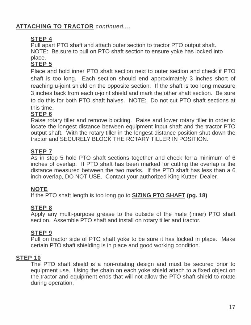
STEP 4 Pull apart PTO shaft and attach outer section to tractor PTO output shaft.
NOTE: Be sure to pull on PTO shaft section to ensure yoke has locked into place.
STEP 5 Place and hold inner PTO shaft section next to outer section and check if PTO
shaft is too long. Each section should end approximately 3 inches short of reaching u-joint shield on the opposite section. If the shaft is too long measure 3 inches back from each u-joint shield and mark the other shaft section. Be sure to do this for both PTO shaft halves. NOTE: Do not cut PTO shaft sections at this time.
STEP 6 Raise rotary tiller and remove blocking. Raise and lower rotary tiller in order to
locate the longest distance between equipment input shaft and the tractor PTO output shaft. With the rotary tiller in the longest distance position shut down the tractor and SECURELY BLOCK THE ROTARY TILLER IN POSITION.
STEP 7 As in step 5 hold PTO shaft sections together and check for a minimum of 6
inches of overlap. If PTO shaft has been marked for cutting the overlap is the distance measured between the two marks. If the PTO shaft has less than a 6 inch overlap, DO NOT USE. Contact your authorized King Kutter Dealer.
NOTE If the PTO shaft length is too long go to SIZING PTO SHAFT (pg. 18) STEP 8 Apply any multi-purpose grease to the outside of the male (inner) PTO shaft
section. Assemble PTO shaft and install on rotary tiller and tractor. STEP 9 Pull on tractor side of PTO shaft yoke to be sure it has locked in place. Make
certain PTO shaft shielding is in place and good working condition. STEP 10 The PTO shaft shield is a non-rotating design and must be secured prior to
equipment use. Using the chain on each yoke shield attach to a fixed object on the tractor and equipment ends that will not allow the PTO shaft shield to rotate during operation.

18
SIZING PTO SHAFT
STEP 1 Cutting the PTO shaft to length. NOTE: Be
sure to cut equal lengths of each PTO shaft section. Clamp end of PTO shaft in a vice and cut off shield where marked. (Figure 1-A & 1-B)
STEP 2 Using cut section of the shield as a guide
cut shaft off the same amount. (Figure 2) STEP 3 Repeat steps 1 and 2 for other PTO shaft
section. STEP 4 Use a file to deburr PTO shafts. Clean up
all chips, burrs and filings from both ends of the PTO shaft.
Figure 1-A
Figure 1-B
Figure 2
19
OPERATING INSTRUCTIONS
STEP 1 Before each use perform the maintenance described in maintenance section (page 20). STEP2 Read, understand, and follow the information on safety training, preparation, starting and stopping safety, operational safety, transport safety warning sections of this man-ual (pages 12 thru 15).
STEP 3 With the rotary tiller positioned on level ground, adjust the tractor lift arms so that when lifted, the rotor bar remains parallel to the ground. STEP 4 With the rotary tiller attached to the tractor, raise and support the tiller with suitable blocks. Adjust the skids, located on the sides of the tiller. The adjustment bolts for both right and left sides should be positioned in the same adjustment hole. This al-lows the tiller to till the same depth on each side. Adjust the back plate, with regulat-ing chain, until the desired mulching effect is found. Note: Never attempt to adjust the rotary tiller while the tractor is running. STEP 5 Raise the tiller and remove the blocks. Lower the tiller to the ground. STEP 6 With the tractor at idle RPM and the tiller lifted off of the ground, engage PTO and slowly advance throttle to 540 PTO RPM. NOTE: Rotary tiller is designed to run at 540 PTO RPM only. STEP 7
Select a low gear for the tractor and begin to move forward. Tractor ground speed is to be controlled by gear selection only and not engine speed. As the tractor moves forward, slowly lower the tiller down. Allow the tiller tines to gradually engage the ground.

Never travel at a fast ground speed while using the tiller, this could damage it. Never attempt to turn the tractor or travel in reverse with the PTO engaged and the tiller in the ground. Always raise the tiller out of the ground when backing up or attempting to turn. Failure to due so may cause damage to the tiller. STEP 8 After each use clean all debris from the tiller tines. Replace any missing or illegible safety decals. Inspect for any damaged or worn parts and replace before next use. Store rotary tiller in a dry environment. MAINTENANCE 1). Periodically check and maintain proper gear oil level. 2). Every 8 hours, (1) grease "out-board hub", (2) PTO shaft universal joints, (3)
PTO shaft safety shield and (4) PTO telescoping surface. NOTE: Use only a grade Type II tube grease.
NOTE: Do not grease the slip clutch assembly. 3). Before each use check to make sure all safety shields are installed and working
properly. 4). Check tiller tines for cracks and breaks before every use. Torque tine bolts to
100 ft/lbs. if you need to replace a tine. 5). Periodically check all nuts and bolts to insure they are tight and secure. The
bolts holding the top gearbox to the base plate and the “L” bracket need to be torqued at 75 ft/lbs. Also the bolts holding the cross over shaft from the top gearbox to the side gearbox should be torqued at 45 ft/lbs.
6). Periodically loosen torque spring bolts and allow slip clutch to slip for approxi-mately two (2) revolutions. Loosen the bolts until the springs lose contact with the flange yoke. This ensures that the slip clutch is not in a "locked" position.
7). Make sure that the clutch slips. 8). To retighten the slip clutch, tighten the torque spring bolts until the nut makes
contact with the flange yoke and further tighten one and a half turns (1-1/2). This is a good starting point , further adjustments may need to be made based on soil conditions.
NOTE: Do not over or under tighten slip clutch assembly or damage may occur.
NOTE: Do not allow the tractor engine or rotary tiller to bog down or stall. This causes undue wear and tear on the tiller and tractor. If this continues to happen reduce ground speed and raise tilling depth of rotary tiller. Never attempt to re-move objects from the rotor bar until the tractor has been shut down and the tiller tines have completely stopped.
WARNING
20

MAINTENANCE SAFETY l Good maintenance is your responsibility. Poor maintenance is an invita-
tion to trouble. l Follow good shop practices. l Keep service area clean and dry l Be sure electrical outlets and tools are properly grounded l Use adequate light for the job at hand. l Make sure there is plenty ventilation. Never operate the engine of the towing
vehicle in a closed building. The exhaust fumes may cause asphyxiation. l Before working on this machine, disengage the PTO, shut off the engine, set the
brakes, and remove the ignition keys. l Be certain all moving parts on attachments have come to a complete stop be-
fore attempting to perform maintenance. l Never work under equipment unless it is blocked securely. l Always use personal protection devices such as eye, hand and hearing protec-
tors, when performing any service or maintenance. l Frequently check tiller tines. They should be sharp, free of nicks and cracks and
securely fastened. l Periodically tighten all bolts, nuts, and screws and check that all cotter pins are
properly installed to ensure unit is in safe condition. l When completing a maintenance or service function, make sure all safety
shields and devices are installed before placing unit in service. l After servicing, be sure all tools, parts and service equipment are removed from
tiller. l Do not allow debris, grease or oil to build up on any deck or platform. l Where replacement parts are necessary for periodic maintenance and servicing,
genuine factory replacement parts must be used to restore your equipment to original specifications.
l The manufacturer will not be responsible for injuries or damages caused by use of unapproved parts and/or accessories.
l A fire extinguisher and the first aid kit should be kept readily accessible while performing maintenance on this equipment.
STORAGE SAFETY l Following operation, or when unhooking the tiller, stop the tractor, set the
brakes, disengage the PTO, shut off the engine and remove the ignition keys. l Store the unit in an area away from human activity. l Do not park equipment where it can be exposed to direct contact to livestock for
long periods of time. Damage and livestock injury could result. l Make sure all parked machines are on a hard, level surface and engage all safe-
ty devices.
21

SAFETY SIGN LOCATIONS The types of safety signs and locations on the equipment are shown in the illustration below. Good safety requires that you familiarize yourself with the various safety signs, the type of warning and the area, or particular function related to that area, that re-quires your SAFTY AWARENESS.
Note: The numbers represent the safety decals on the following pages. REMEMBER: If safety signs have been damaged, removed, become illegible or parts have been replaced without signs, new safety signs must be applied. New safety signs are available from your authorized dealer, distributor or factory.
Top View
22

23
1
2

24
3
4

25
5
6

26
7
8

27
22” PTO 147122
Ref. No. Part # 1 Safety Shield 197127
2 Roll Pin 170120
3 Male Tube End Yoke 151045
4 Female Tube End Yoke 151050
5 Tractor End Yoke 151035
6 Inner Tube 14 Series 151090
7 Outer Tube 14 Series 151091
8 Cross Kit # 4 170015
9 Quick Disconnect Pin 170110
10 Clutch Spring w/ Compression Bolts & nuts (Pkg. 8) 500150
11 Flanged Yoke 140226
12 Bushing 140221
13 Friction Hub 140220
14 10 x 70 Bolt 140224
15 Pressure Plate (Outer) 140216
16 Friction Disc for 6” Slip Clutch (4-3/4” OD x 2-11/16” ID) 140219
16 Friction Disc for 7” Slip Clutch (5-1/2” OD x 3-5/16” ID) 196008
17 Inner Disc 124317

28
XB & XBX TILLER: EXPLODED VIEW

29
TG-48-XB & TG-54-XBX TILLER PARTS LIST
Ref. No. Model # TG-48-XB TG-54-XBX
1 Lift Arm Brace 381001 381001
2 Lift Arm (LH) 404404 404404
3 Lift Arm (RH) 404405 404405
4 Tail Rod Assembly 505116 505117
5 Center Shield Assembly 505020 505020
6 Lift Arm Spacer Kit 505021 505021
7 Tine Pkg. (1-Right,1-Left) w/ Bolts 505002 505002
7 Tine Pkg. (3-Right,3-Left) w/ Bolts 505006 505006
7 Complete Tine Pkg. (36 pcs.) 505036 505036
8 Tine Bolt Pkg. (12 pcs.) 505012 505012
8 Tine Bolt Pkg. (72 pcs.) 505072 505072
9 Skid Assembly Left or Right 505060 505060
10 PTO Shaft w/ 6” Clutch Only 147122 147122
11 Chain & Shackle Kit 505140 505140
12 Top Gearbox 184073 184073
13 Lift Pins Cat. 1 (2/Pk) 500001 500001
14 Rotor CALL CALL
15 Back Plate 404406 404415
16 Support Stand Assembly 505022 505022
17 Hub Stub Shaft w/Disc See Page34 See Page34
18 Side Gearbox Hub & Shaft w/Disc See Page 30 See Page 30
Part #

30
TG-48-XB & TG-54-XBX SIDE GEARBOX PARTS

31
TG-48-XB & TG-54-XBX SIDE GEARBOX PARTS LIST
Ref. No. Part # Model # TG-48-XB
2 Hub 977028
3 Oil Seal (55 X 78 X 12) Dbl Lip 977029
4 Bearing (ISO 1209) 977030
5 Snap Ring (ID 85mm X OD 90.5) 977031
6 Spacer (55 X 46 X 23.5) 977032
7 Spur Gear (27 Teeth) 977033
8 Snap Ring (45mm X ID 41.5) 977034
9 Housing 977035
10 Bearing (6010) 977036
11 Snap Ring (50mm X ID 45.8) 977037
12 Spur Gear (38 Teeth) 977038
13 Gasket Round 977039
14 Gasket 977040
15 Pipe Plug 1/2” - 14 NPT 977019
16 Pressure Relief Plug 1/2” - 14NPT 902007
17 Hex Cap Screw, Lockwasher(Pkg.4) 505024
18 Cover 977041
19 Hex Cap Screw, Lock Washer, Nut (8-Pk) 505023
20 Snap Ring (80mm X OD 85.5) 977046
Part # TG-54-XBX
977028
977029
977030
977031
977032
977033
977034
977035
977036
977037
977038
977039
977040
977019
902007
505024
977041
505023
977046
1 Side Gearbox Hub & Shaft w/Disc 100106 100106

32
TG-48-XB & TG-54-XBX SERIES TOP GEARBOX

33
TG-48-XB & TG-54-XBX SERIES TOP GEARBOX PARTS LIST
Ref. No. Part # Model # TG-48-XB
2 Input Shaft 977002
3 Retaining Ring 30mm x 27.9 ID 977003
4 Bevel Pinion (13 Teeth) 977004
5 Bearing Cone (30305) 977005
6 Bearing Cup (30305) 977006
7 Bearing Cone (32007x) 977007
8 Bearing Cup (32007x) 977008
9 Retaining Ring 62mm X 66 OD 977009
10 Output Shaft 977010
11 Hub Cap 977011
12 Bearing (6307) 155007
13 Shim Pkg. (2) 1mm & (2) .5mm 502243
14 Bevel gear (19Teeth) 977012
15 Retaining Ring 34mm X 31.5 ID 977013
16 Seal Input (13997) 35 X 62 X 8 977014
17 Freeze Plug 977015
18 Spacer 45 X 36 X 12.4 977016
19 Spur Pinion (18 Teeth) 977017
20 Gasket 977018
21 Hex Cap Screw, Lockwasher(4-Pk) 505024
22 Pressure Relief Plug 1/2” - 14NPT 902007
23 Flange Plug 1/2” - 14NPT 977019
24 Shim, Input OD 60 X ID 50 977022
25 Flange Plug (M10 - 1.0) 977023
26 O-Ring(- 011) 977024
Part # TG-54-XBX
977002
977003
977004
977005
977006
977007
977008
977009
977025
977026
155007
502243
977012
977013
977014
977015
977016
977017
977018
505024
902007
977019
977022
977023
977024
1 Housing 977001 977001

TG-48-XB & TG-54-XBX HUB PARTS
34

Ref. No. Part # 1 Hub 977047
2 Hub Stub Shaft w/Disc 100107
3 Bearing (6208) 977048
4 Oil Seal (55 X 72 X 9) 977049
5 Snap Ring (40 x 1.5) 40mm X ID 36.5 977050
6 Snap Ring (80 x 2.5) 977046
7 Gasket 977039
8 Mounting Plate 977051
9 Cover 977052
10 Lock Washer (M10) 977021
11 Hex Cap Screw (M10-1.5 x 35) 977053
12 Nut (M10 -1.5) 977054
13 Grease Zerk (1/4”) 132018
35

1. Limited Warranty. King Kutter, Inc. (“King Kutter”), P.O. Box 1200, Winfield, Alabama 35594, warrants to the original retail pur-chaser (“Purchaser”) that the product that is the subject of this sale is free from defects in material and work-manship at the time of sale. Under this warranty, King Kutter will repair the defective product free of charge to the Purchaser, with either new or used and reconditioned replacement parts. All warranty service will be performed at service centers designated by King Kutter. If King Kutter is unable to repair the product to conform to the warranty after a reasonable number of attempts, King Kutter will provide, at its option, one of the following: (a) a replacement for the product or, (b) a full refund of the purchase price. Repair, replacement, or refunds are the Purchas-er’s EXCLUSIVE remedies against King Kutter under this limited warranty. King Kutter will not be liable for any special, incidental or consequential damages based upon breach or warranty, breach of contract, negli-gence, strict tort liability, or any other legal theory. Such damages include, but are not limited to, loss of prof-its, loss of savings or revenue, loss of use of the product or any associated equipment, cost of capital, cost of any substitute equipment, facilities or services, down time, the claims of third parties including customers, and injury to property. These limitations also apply, to the extent allowed by law, to personal injury. The purchaser must notify the Seller in writing of any defect in material or workmanship within one (1) year following the date of purchase. If the equipment is used for commercial purposes, the Purchaser must notify the Seller in writing of any defect in material or workmanship within ninety (90) days following the date of pur-chase. In no event will King Kutter be liable under this warranty unless written notice is received by the Seller within one (1) year from the date of original retail sale. 2. Warranty of Title. King Kutter warrants that it transfers a good title to the product free of any encumbrances, and free of the rightful claim of any third party for infringement of patent or copyright. 3. What is Not Covered by This Limited Warranty. King Kutter will not be responsible for damage to or failure in the product which results from accident, misuse, abuse, neglect, installation of attachments not provided by King Kutter, modifications to the product, or dam-age caused by use of the product for purposes other than those for which it was designed. 4. No Other Warranties. Unless modified in writing and signed by both parties, this agreement is understood to be the complete and exclusive agreement and warranty between King Kutter and Purchaser, superseding all prior agreements, oral and written, and all other communication between King Kutter and Purchaser related to the subject mat-ter of this agreement. THIS LIMITED WARRANTY IS IN LIEU OF ALL OTHER WARRANTIES, EXPRESS OR IMPLIED, INCLUD-ING, BUT NOT LIMITED TO, THE IMPLIED WARRANTY OF MERCHANTABILITY AND THE IMPLIED WARRANTY OF FITNESS FOR A PARTICULAR PURPOSE. No employee of King Kutter nor anyone else is authorized to make any warranty or representation in addition to or different from those made in this agree-ment. 5. Allocation of Risk. This agreement allocates the risk of product failure between King Kutter and the Purchaser. This Allocation is recognized by both parties as reflected in the price of the goods. The Purchaser acknowledges that he or she has read this agreement, understands it, and is bound by its terms.
KK008