Embed Size (px)
Citation preview
The complementary use of IDEF The complementary use of IDEF and UML modelling approachesand UML modelling approaches
第四組第四組M9401106 M9401106 莊承勳莊承勳M9401201 M9401201 陳德熙陳德熙M9401204 M9401204 吳炳煌吳炳煌M9401205 M9401205 吳自晟吳自晟
GuideGuide AbstractAbstract IntroductionIntroduction Background information on IDEF modelling Background information on IDEF modelling
constructsconstructs Background information on UML modelling Background information on UML modelling
constructsconstructs Analogy drawn between the use of IDEF and UML Analogy drawn between the use of IDEF and UML
for modelling business systemsfor modelling business systems Generating UML models from IDEF models---a Generating UML models from IDEF models---a
domain studydomain study ConclusionConclusion
AbstractAbstract
This study illustrates how semantic This study illustrates how semantic information encoded by different information encoded by different types of IDEF diagramming technique types of IDEF diagramming technique can be re-represented and reused as can be re-represented and reused as models expressed in alternative models expressed in alternative notations. notations.
The study illustrates benefits gained The study illustrates benefits gained from using IDEF as a business front from using IDEF as a business front end to UML.end to UML.

IntroductionIntroduction A shift in the industrial usage of IT system
s has been identified as moving from the application of ‘‘data-driven environments’’ to that of ‘‘co-operative information and knowledge driven environments’’
(1) enterprise modeling (1) enterprise modeling (2) enterprise integration (2) enterprise integration
(1) enterprise modeling (1) enterprise modeling
Enterprise modelling methods, architectures and Enterprise modelling methods, architectures and tools can be used in support of the life cycle engitools can be used in support of the life cycle engineering of large scale, complex and changing sysneering of large scale, complex and changing systemstems
The IDEF suite of enterprise modeling approacheThe IDEF suite of enterprise modeling approache
s, which comprises IDEF0, IDEF1,IDEF1x, IDEF3 as, which comprises IDEF0, IDEF1,IDEF1x, IDEF3 and other graphically based modeling Notations hnd other graphically based modeling Notations have been applied extensively in support of large iave been applied extensively in support of large industrial engineering projects.ndustrial engineering projects.
The Disadvantage of IDEFThe Disadvantage of IDEF
The IDEF modelling concept is no overarchiThe IDEF modelling concept is no overarching modelling framework that has been formng modelling framework that has been formally defined to interconnect individual IDEF ally defined to interconnect individual IDEF notations.notations.
When carrying out multi-perspective modellWhen carrying out multi-perspective modelling of any given complex domain, difficultieing of any given complex domain, difficulties will arise in communicating various domais will arise in communicating various domain concerns between different domain expern concerns between different domain experts.ts.
(2) Enterprise Integration (EI).(2) Enterprise Integration (EI).
The development of The development of distributed-object distributed-object technology.technology.
The development ofThe development of object-based object-based methods that enable IT systems to be methods that enable IT systems to be reused, reconfigured and scaled up and reused, reconfigured and scaled up and down is made possible by deploying a down is made possible by deploying a structured approach to software system structured approach to software system analysis and design.analysis and design.
(2) Enterprise Integration (EI).(2) Enterprise Integration (EI).
The The object-based object-based approach can approach can provide a framework for provide a framework for interoperation between software interoperation between software objects that may be referred to as objects that may be referred to as software components of IT systems. software components of IT systems.
UML is a UML is a object-basedobject-based methods. methods.
The Disadvantage of IDEFThe Disadvantage of IDEF
IDEF modelling notations were designed to provide IDEF modelling notations were designed to provide means of modelling enterprises in their entirety, so means of modelling enterprises in their entirety, so as to systematically deliver abstract representations as to systematically deliver abstract representations of different enterprise views that can be used by conof different enterprise views that can be used by concerned parties in different ways.cerned parties in different ways.

Goal of This paperGoal of This paper
The coherent use of IDEF and UML The coherent use of IDEF and UML models can offer significant potential to models can offer significant potential to develop develop
(i) large scale IT systems(i) large scale IT systems (ii) IT systems of limited scope that can (ii) IT systems of limited scope that can
be readily integrated into large scale co-be readily integrated into large scale co-operative information-drive operative information-drive environments.environments.
Background information on IDEF modelling Background information on IDEF modelling constructsconstructs
IDEF0 function modelling methodIDEF0 function modelling method IDEF1x data modelling methodIDEF1x data modelling method IDEF3 process modelling methodIDEF3 process modelling method IDEF3 provides two main groups of mod
elling mechanism (1)Process Flow Network (PFN) (2)Object State Transition Network (OSTN)
Process Flow Network (PFN)Process Flow Network (PFN)
Process Flow Networks represent the order in which, and conditions under which, activities are performed by a system.
PFN notation is based on the use of the four elements, namely: units of behaviour (UOB); junction; link; and referent.
Object State Transition NetworkObject State Transition Network
The Object State Transition Network describes the ‘‘transition states’’ that an object can pass through during the execution of a specific process.
OSTNs are constructed and represented graphically using state symbol, transition jun
ction, transition link and related UOB modelling constructs.
Background information on UML Background information on UML modelling constructsmodelling constructs
UML UML use caseuse case diagram diagram UML class diagram ( UML class diagram ( staticstatic ) ) DynamicDynamic modelling modelling
state diagramstate diagram
Activity diagramActivity diagram
Sequence diagramSequence diagram
collaboration diagramcollaboration diagram
The Unified Modelling Language (UML)
UML is a widely used de facto standard obUML is a widely used de facto standard object oriented visual modelling language.ject oriented visual modelling language.
It provides a set of modelling notations designed to support various domain specialisms and life phases involved in the engineering of object-oriented software systems.
UML use case and use case UML use case and use case diagramdiagram
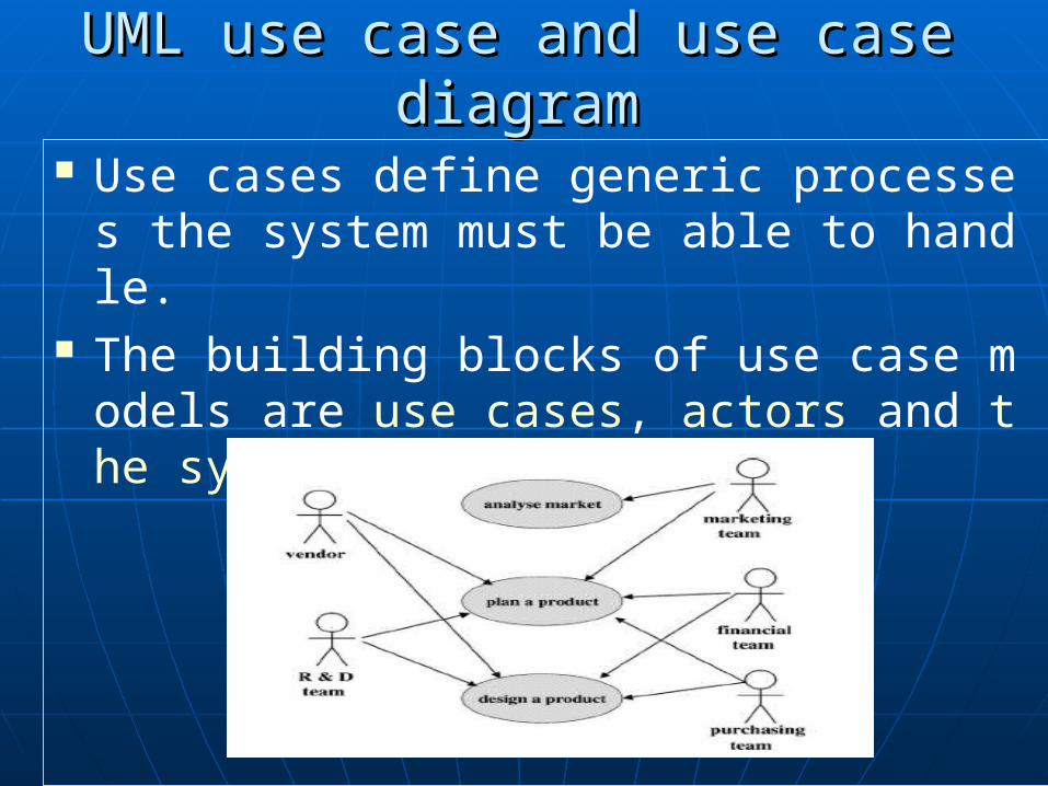
Use cases define generic processes the system must be able to handle.
The building blocks of use case models are use cases, actors and the system modelled.
UML class programs ( static)UML class programs ( static) The term ‘‘class’’ is a descriptor used in U
ML notation to refer to a set of objects with similar d
ata structure, behaviour and relationships. A class diagram can be used to provide a static v
iew of a system in terms of its object classes and the relationships among those classes.
Dynamic modellingDynamic modelling In UML notation, object interactions are desc
ribed using a dynamic model. UML provides modelling constructs to constr
uct four types of dynamic diagram, namely state diagrams, sequence diagrams, collaboration diagrams
and activity diagrams.
State diagramState diagram
A state diagram can show all possible states that can be reached by objects of the class, and which events trigger/cause state changes. An event can be encoded by an object initiating a message.
Activity diagram
Activity diagrams are used to model flows of activities, such as activities comprising a procedure.
In UML, it is assumed that states will be changed by activities, while transitions will be related to actions.
Sequece diagram
A sequence diagram is used to show how objects and actors take part in a collaboration. It defines and illustrates the sequence in which objects pass messages to each other.

Collaboration diagram
In UML notation, collaboration defines relationships between a set of objects in a particular context.
Collaboration diagrams can be used to show the sequence in which events occur by describing the structural organisation of objects that exchange messages
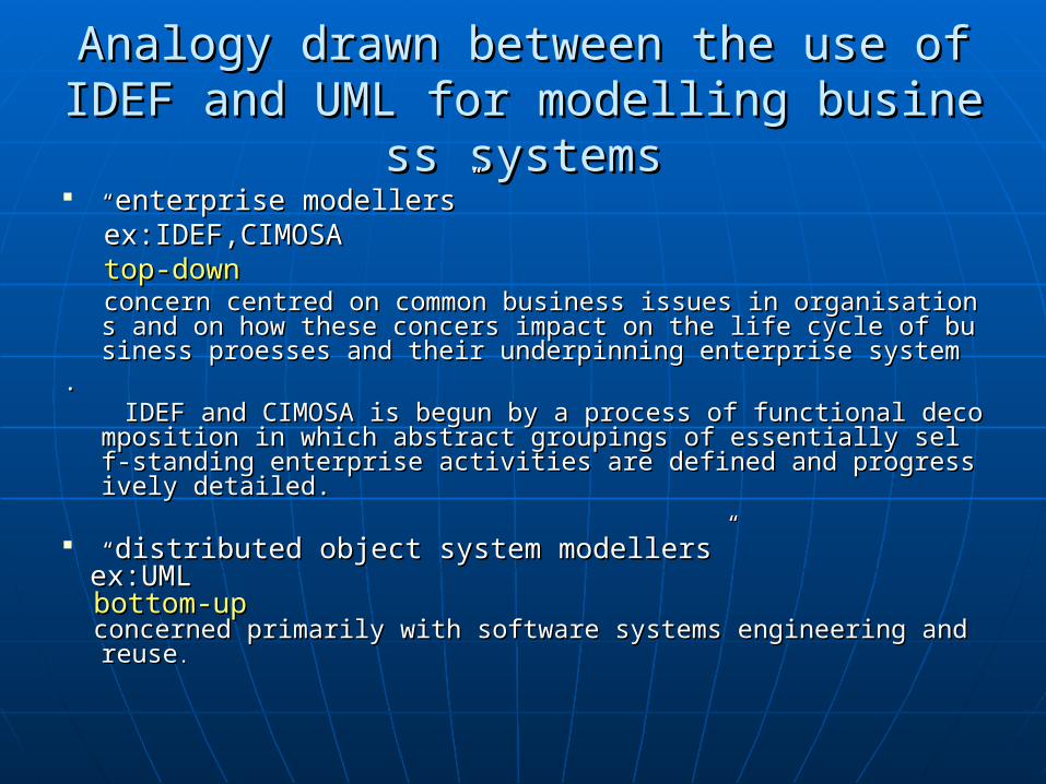
Analogy drawn between the use of IDEF anAnalogy drawn between the use of IDEF and UML for modelling business systemsd UML for modelling business systems
““enterprise modellersenterprise modellers”” ex:IDEF,CIMOSAex:IDEF,CIMOSA top-downtop-down concern centred on common business issues in organisations and on how concern centred on common business issues in organisations and on how
these concers impact on the life cycle of business proesses and their unthese concers impact on the life cycle of business proesses and their underpinning enterprise systemderpinning enterprise system
.. IDEF and CIMOSA is begun by a process of functional decomposition in wIDEF and CIMOSA is begun by a process of functional decomposition in w
hich abstract groupings of essentially self-standing enterprise activities hich abstract groupings of essentially self-standing enterprise activities are defined and progressively detailed.are defined and progressively detailed.
““distributed object system modellersdistributed object system modellers”” ex:UMLex:UML bottom-upbottom-up concerned primarily with software systems engineering and reuseconcerned primarily with software systems engineering and reuse..
A UML view of enterprise A UML view of enterprise engineering issuesengineering issues
The UML has emphasised the importancThe UML has emphasised the importance of defining “objects”.e of defining “objects”.
Eriksson and Penker refer in UML terms tEriksson and Penker refer in UML terms to the following types of object:o the following types of object:
ResourcesResources, , ProcessesProcesses, , GoalsGoals,, RulesRules, , MetamodelsMetamodels..
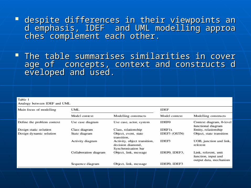
despite differences in their viewpoints and emphasis, Idespite differences in their viewpoints and emphasis, IDEF and UML modelling approaches complement eacDEF and UML modelling approaches complement each other. h other.
The table summarises similarities in coverage of concThe table summarises similarities in coverage of concepts, context and constructs developed and used. epts, context and constructs developed and used.
Generating UML models from IDEF Generating UML models from IDEF models---a domain studymodels---a domain study
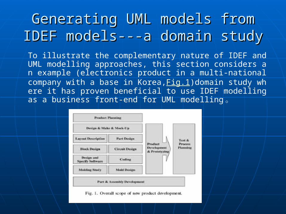
To illustrate the complementary nature of IDEF and UML modelling approaches, this section considers an example (electronics product in a multi-national company with a base in Korea,Fig.1)domain study where it has proven beneficial to use IDEF modelling as a business front-end for UML modelling 。
IDEF modelling during the domain study
IDEF0 modelThe product development process encompassed ‘‘product planning’’ through to ‘‘prototype product development’’ 。
Fig.2Fig.2 shows the top-level IDEF0 context diagram Fig.3 is IDEF0 functional diagram ‘‘develop a new product’’Fig.4 is‘‘design a part’’Fig.5 is‘‘record a new part’’

IDEF1X modelLike many products in this domain, the particular electronic consumer product is composed of both mechanical parts and electronic-electrical-mechanical parts, can be usefully described as a hierarchical structure expressed using IDEF1x modelling constructs.Fig.6 product levelFig.7 assembly level
IDEF3 modelIDEF3 modelIDEF3 units of behaviour are reference objects that can describe process flows, conditions and events 。Fig.8Fig.8 IDEF3 PFN IDEF3 PFNFig.9Fig.9 IDEF3 OSTN IDEF3 OSTN
UML model
Use case diagramsFig.10 shows a UML use case-centred view which has been drawn from IDEF0 models shown in Fig.2 and Fig.3。
Class diagramsFig.11 shows a class diagram developed by Fig.5 and Fig.6。Fig. 12 shows dependency relationships derived for the function class ‘‘register-a-new-part’’ and its related classes
State diagramState diagramState diagrams describe possible conditions of objects, the IDEF3 OSTN may be used to derive inputs to a UML state diagram 。
Fig.13 shows a UML state diagram derived from semantic information previously encoded by Fig.9。
Activity diagramInformation contained in an IDEF3 PFN can be used to develop equivalent UML activity diagrams.
Fig. 14 shows a UML activity diagram derived from the IDEF3 PFN shown in Fig. 8
Sequence diagramSequence diagramSequence diagrams can be derived from information contained in equivalent IDEF0 or IDEF3 models 。
Fig.15 shows a sequence diagram derived from Fig.5 which represents the sequence involved in registering a new part 。
Collaboration diagramCollaboration diagramCollaboration diagrams can also be derived from semantic information previously encoded within IDEF0 or IDEF3 models 。
Fig.16 shows an example collaboration diagram, which represents similar information to that contained in Fig.15 。
The benefits arising from the combined use of IDEF and UML
There is no explicit way in UML of linking abstract descriptions of process and resource requirements and structure to detailed descriptions of object behaviours and structure. For the case study example of product engineering, the combined use of IDEF and UML much improved this situation.
There is a need for frequent engineering There is a need for frequent engineering change in that company :change in that company :
requirements changerequirements change product technology changeproduct technology change business and manufacturing process business and manufacturing process
changechange
Enterprise situations different groupings of Enterprise situations different groupings of personnel were involved in deciding :personnel were involved in deciding :
what the enterprise should dowhat the enterprise should do
(IDEF)(IDEF) how the what might best be achieved how the what might best be achieved
(UML)(UML) doing what was necessary when it had doing what was necessary when it had
been decided how the what should be been decided how the what should be donedone
FIG
ConclusionConclusion In the near future component-based enterprise systems In the near future component-based enterprise systems
should be designed, constructed, distributed, integrateshould be designed, constructed, distributed, integrated and changed with a common ‘‘big picture’’ in mid and changed with a common ‘‘big picture’’ in mind. nd.
There is no direct one-to-one mapping of modelling conThere is no direct one-to-one mapping of modelling constructsstructs
CIMOSACIMOSA ( CIM Open System Architecture )( CIM Open System Architecture )
CimosaCimosa provides multi-perspective diagram provides multi-perspective diagramming templates and welldefined and intercoming templates and welldefined and interconnected sets of modelling constructs to enconnected sets of modelling constructs to encode business, people and IT aspects of enterprde business, people and IT aspects of enterprise requirements .ise requirements .
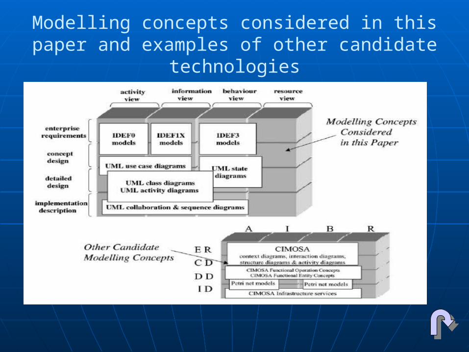
Modelling concepts considered in this paper and examples of other candidate technologies

The EndThe End ~Thank You~~Thank You~
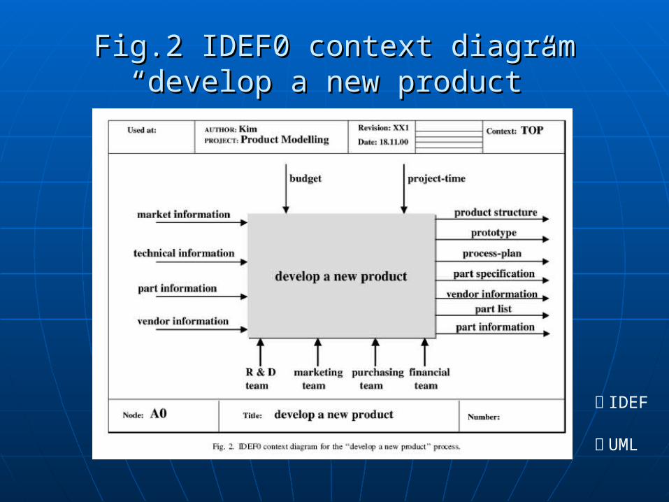
Fig.2 IDEF0 context diagramFig.2 IDEF0 context diagram“develop a new product”“develop a new product”
回 IDEF
回 UML
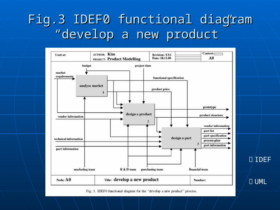
Fig.3 IDEF0 functional diagramFig.3 IDEF0 functional diagram“develop a new product”“develop a new product”
回 IDEF
回 UML
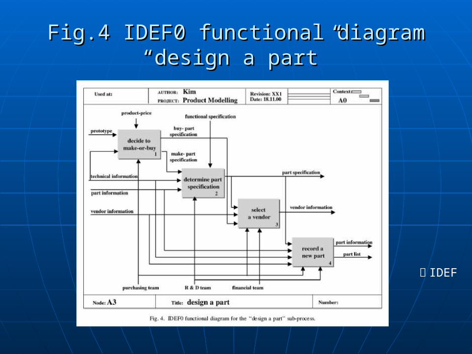
Fig.4 IDEF0 functional diagramFig.4 IDEF0 functional diagram“design a part”“design a part”
回 IDEF
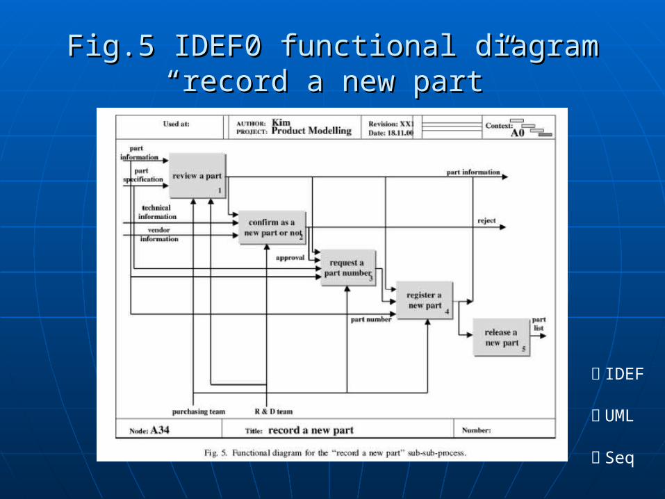
Fig.5 IDEF0 functional diagramFig.5 IDEF0 functional diagram“record a new part”“record a new part”
回 IDEF
回 UML
回 Seq

Fig.6 IDEF1x model developed at the Fig.6 IDEF1x model developed at the product levelproduct level
回 IDEF
回 UML

Fig.7 IDEF1x model developed at the assmeFig.7 IDEF1x model developed at the assmembly levelmbly level
回 IDEF
回 UML
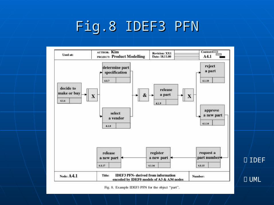
Fig.8 IDEF3 PFNFig.8 IDEF3 PFN
回 IDEF
回 UML
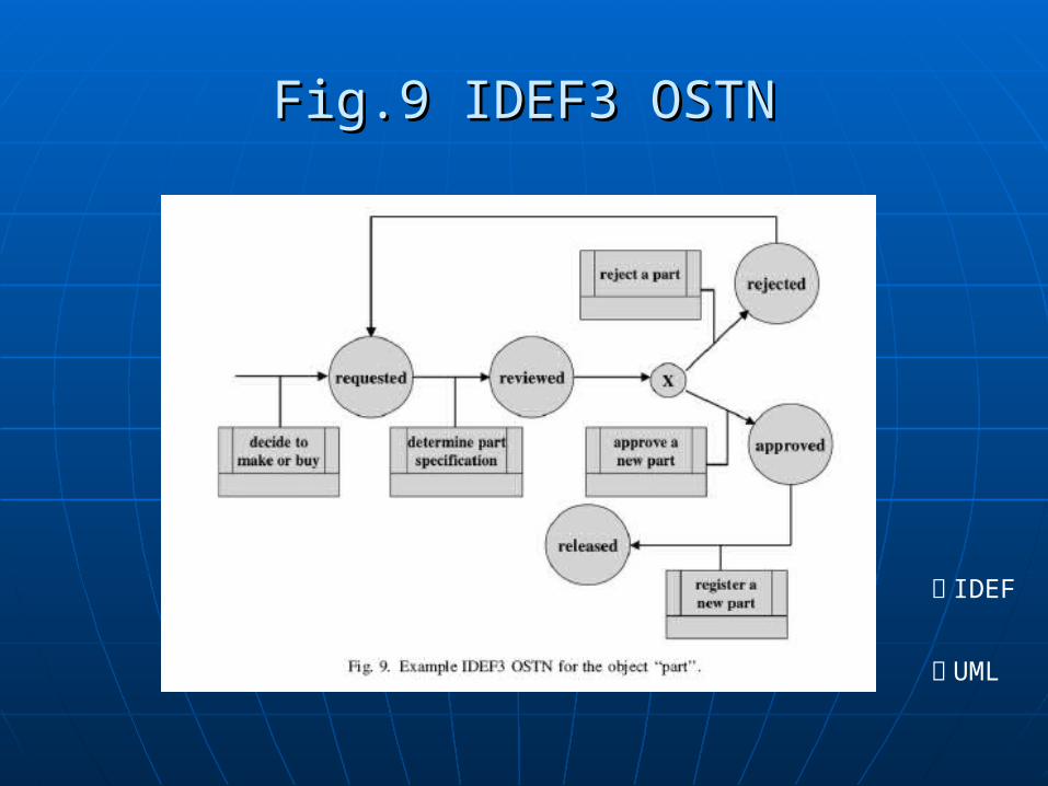
Fig.9 IDEF3 OSTNFig.9 IDEF3 OSTN
回 IDEF
回 UML
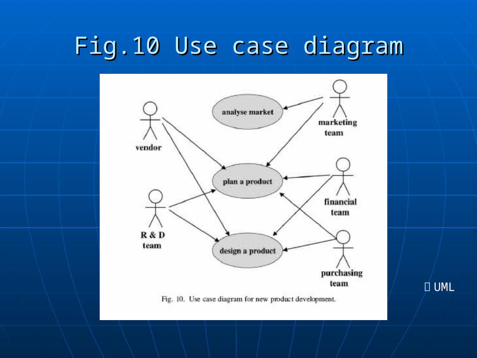
Fig.10 Use case diagramFig.10 Use case diagram
回 UML
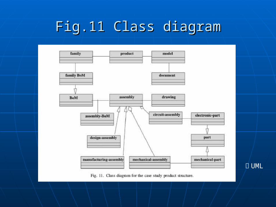
Fig.11 Class diagramFig.11 Class diagram
回 UML
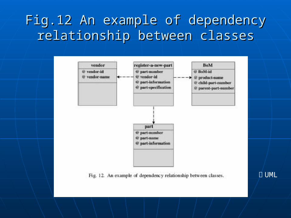
Fig.12 An example of dependency Fig.12 An example of dependency relationship between classesrelationship between classes
回 UML
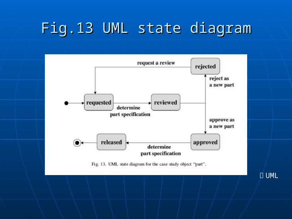
Fig.13 UML state diagramFig.13 UML state diagram
回 UML
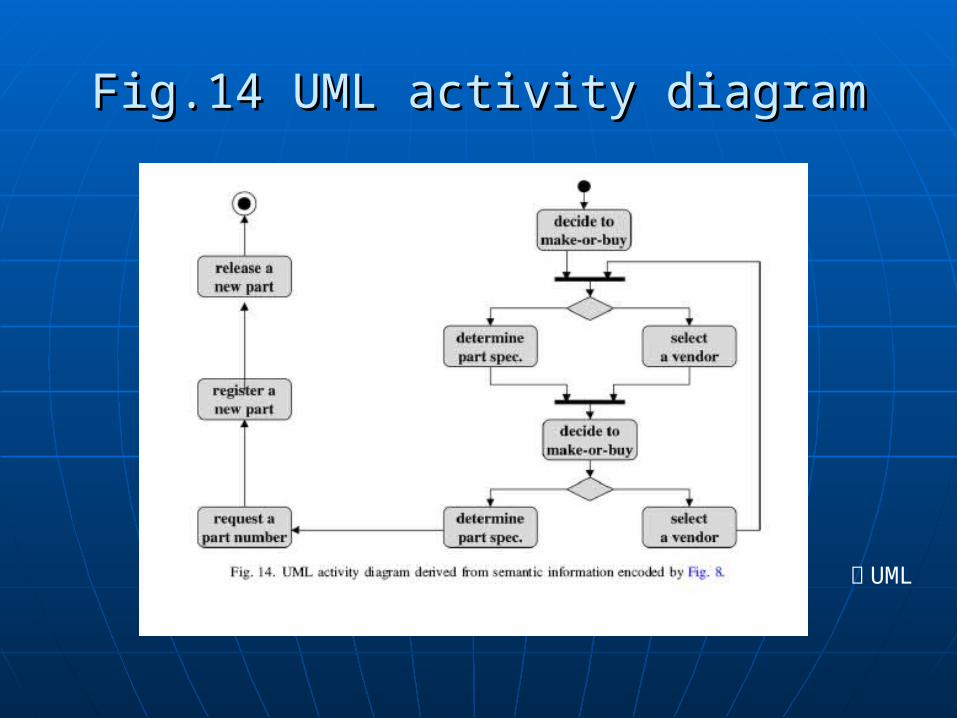
Fig.14 UML activity diagramFig.14 UML activity diagram
回 UML
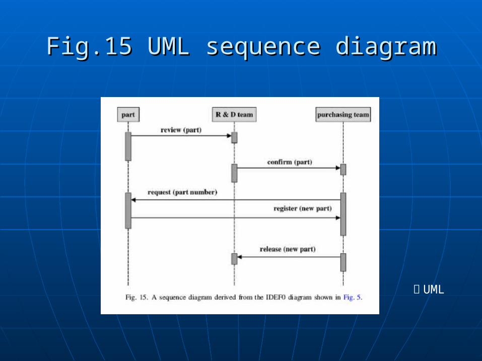
Fig.15 UML sequence diagramFig.15 UML sequence diagram
回 UML
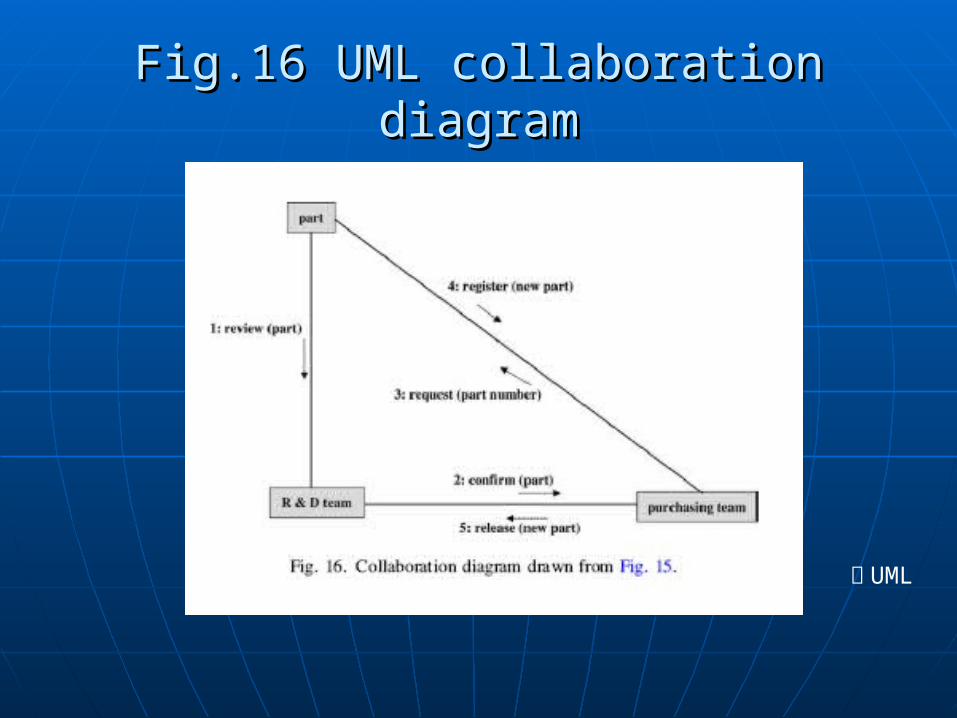
Fig.16 UML collaboration diagramFig.16 UML collaboration diagram
回 UML