Embed Size (px)
Citation preview
The GridThe Grid
Kyle Thornton DMI 50B
Kyle Thornton DMI 50B
What Is A Grid?
Invented in 1913 by Gustaf Bucky– Consisted of a framework containing lead foil strips
standing on edge, parallel and equidistant to each other
In 1920, Hollis Potter invented a mechanism for suspending the grid in a framework that moved between the patient and film– The motion eliminated the grid lines in the image
The grid is the most effective way to remove secondary radiation from large radiographic fields
What Does A Grid Do?
A grid is an important radiographic tool A grid absorbs scatter radiation before it
reaches the film A grid improves contrast on the film A grid has a special composition and
many different types Used properly, the grid is a technologist’s
best friend
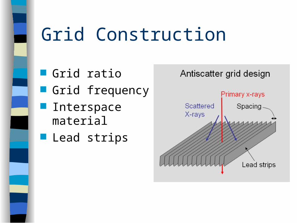
Grid Construction
Grid ratio Grid frequency Interspace material Lead strips
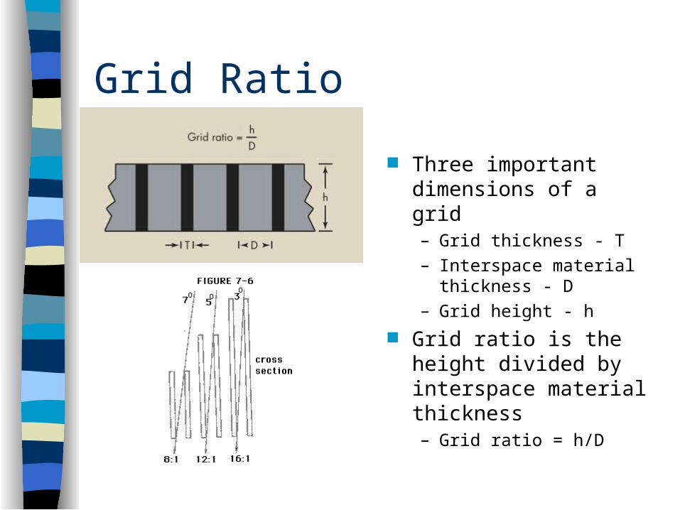
Grid Ratio
Three important dimensions of a grid– Grid thickness - T– Interspace material
thickness - D– Grid height - h
Grid ratio is the height divided by interspace material thickness– Grid ratio = h/D
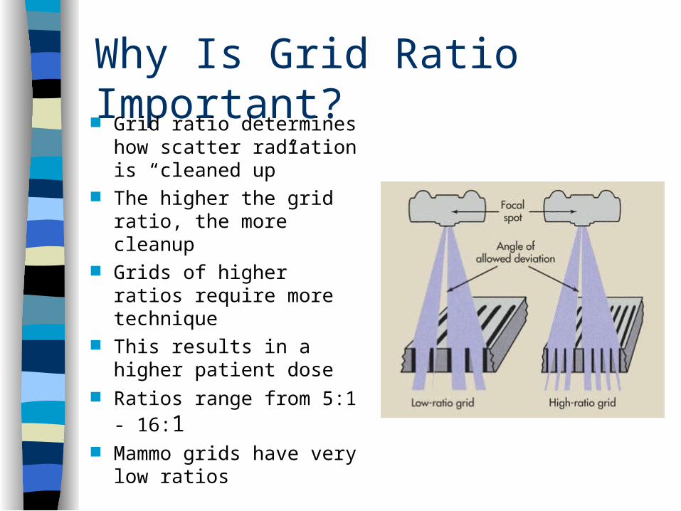
Why Is Grid Ratio Important? Grid ratio determines
how scatter radiation is “cleaned up”
The higher the grid ratio, the more cleanup
Grids of higher ratios require more technique
This results in a higher patient dose
Ratios range from 5:1 - 16:1
Mammo grids have very low ratios
Grid Ratio Equation
The distance between each grid strip is 200 m and the height is 2.4 mm. What is the grid ratio?
Hint: Ratio = h/D Step 1 – Identify h Step 2 – Identify D Step 3 – ???? Step 4 - ????
Grid Frequency
The number of strips or lines per inch or centimeter is grid frequency
Higher frequencies display less lines Higher frequencies affect patient dose Higher frequencies are generally associated with
higher ratios Most grid frequencies are 60-110 lines/inch Mammo grids have very high frequencies, but low
ratios
Interspace Material
The material between the grid strips Maintains a precise separation between
the strips Generally constructed from aluminum or
plastic fiber Aluminum has definite advantages over
fiber
Grid Strips
Should be very thin and have high scatter absorption properties
Lead is best The entire grid is encased in aluminum
for protection Sometimes it is further encased in
plastic for more protection
Grid Performance
Contrast improvement factor Bucky factor Selectivity
Contrast Improvement Factor
Grids remove scatter radiation before it reaches the film
Therefore it improves contrast Contrast improvement factor compares
contrast improvement with a grid to that without a grid
Contrast Improvement Factor Equation K = Radiographic contrast with grid
• Radiographic contrast without grid
Most grids have a contrast improvement of 1.5 - 2.5
Contrast improvement is higher with higher ratio grids
Lead content also determines contrast improvement
Bucky Factor
Also called grid factor This compares the increased technique necessary for
grid use Bucky factor will increase with with increasing grid
ratio It will also increase with increasing kVp B = Incident remnant radiation
• Transmitted remnant radiation The amount of radiation hitting the grid will always be
greater than the amount hitting the film
Grid Selectivity
Related to grid construction itself The total lead content of the grid has an
influence on selectivity The more lead, the more cleanup = Primary radiation transmitted through grid
• Scatter radiation transmitted through grid
General Rules Of Grid Characteristics High ratio grids have high contrast
improvement factors High frequency grids have thin strips of
interspace material and low contrast improvement factors
Heavy grids have high selectivity and high contrast improvement factors
Grid Types
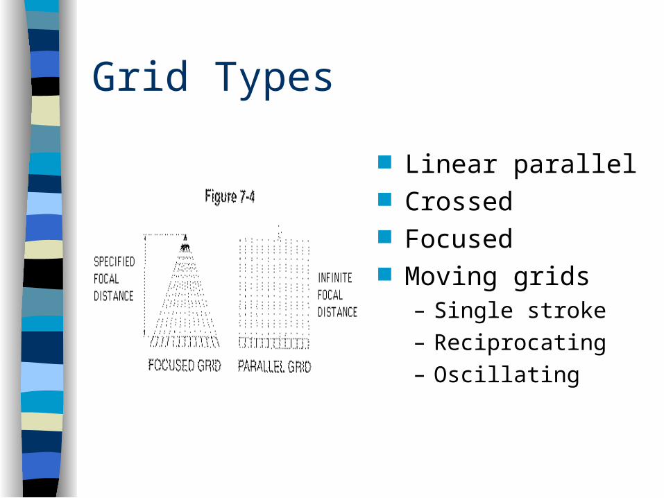
Linear parallel Crossed Focused Moving grids
– Single stroke – Reciprocating– Oscillating
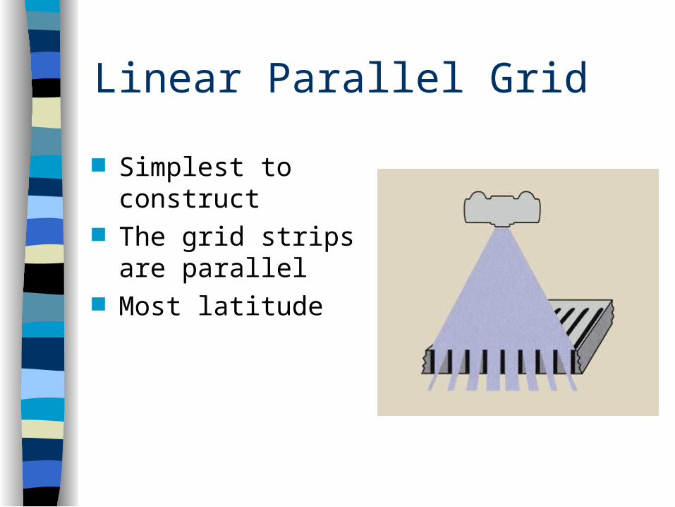
Linear Parallel Grid
Simplest to construct
The grid strips are parallel
Most latitude
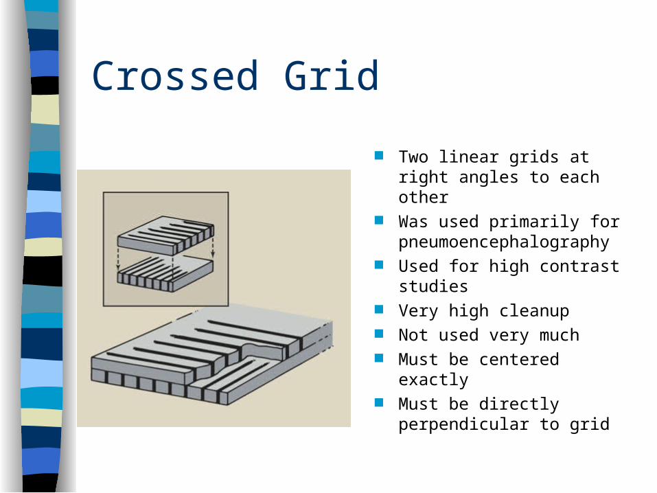
Crossed Grid
Two linear grids at right angles to each other
Was used primarily for pneumoencephalography
Used for high contrast studies
Very high cleanup Not used very much Must be centered exactly Must be directly
perpendicular to grid
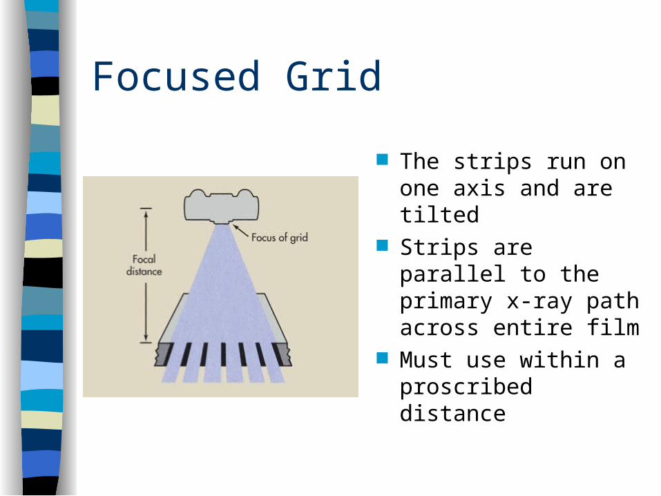
Focused Grid
The strips run on one axis and are tilted
Strips are parallel to the primary x-ray path across entire film
Must use within a proscribed distance
Moving GridsSingle Stroke Antiquated Grid had to be cocked with a spring
mechanism Worked in synch with exposure time The mechanism moved once
throughout exposure Had to be reset for each exposure
Reciprocating Grid
Moves back and forth during exposure Motor driven Does not have to be reset for each
exposure
Oscillating Grid
Similar to a reciprocating grid Moves in a circular motion as opposed
to back and forth
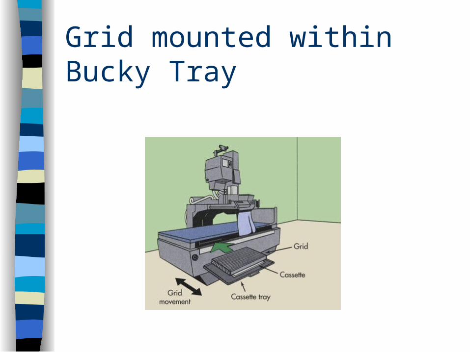
Grid mounted within Bucky Tray
Advantages And Disadvantages Of Moving Grids
Advantages– No grid lines– Problems occur infrequently
Disadvantages Mechanical problems may occur Very infrequently, motion is detected on
radiograph
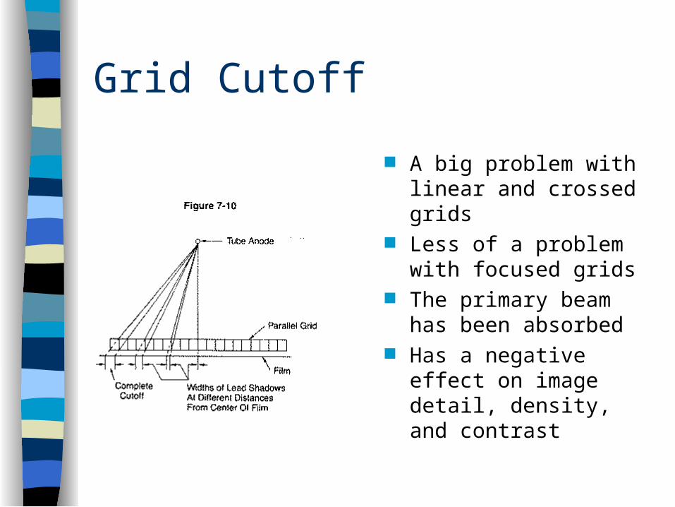
Grid Cutoff
A big problem with linear and crossed grids
Less of a problem with focused grids
The primary beam has been absorbed
Has a negative effect on image detail, density, and contrast
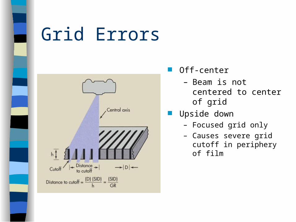
Grid Errors
Off-center– Beam is not centered to
center of grid Upside down
– Focused grid only
– Causes severe grid cutoff in periphery of film
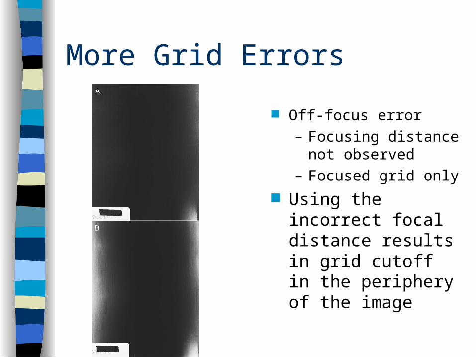
More Grid Errors
Off-focus error– Focusing distance
not observed – Focused grid only
Using the incorrect focal distance results in grid cutoff in the periphery of the image
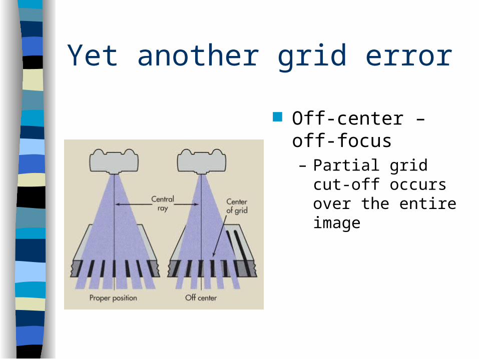
Yet another grid error
Off-center – off-focus– Partial grid cut-off
occurs over the entire image
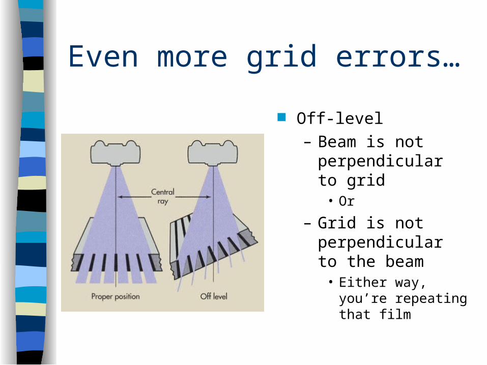
Even more grid errors…
Off-level– Beam is not
perpendicular to grid• Or
– Grid is not perpendicular to the beam
• Either way, you’re repeating that film
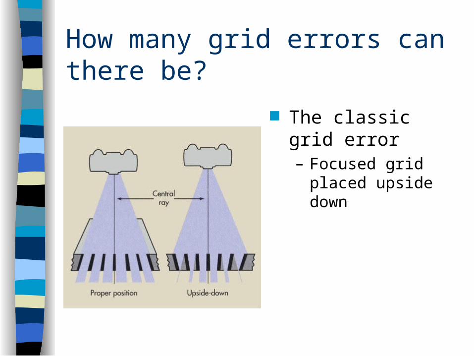
How many grid errors can there be?
The classic grid error– Focused grid placed
upside down
Demo of Focused Grid Used Upside Down
http://www.youtube.com/watch?v=HS4DPt0Gjz0&feature=related
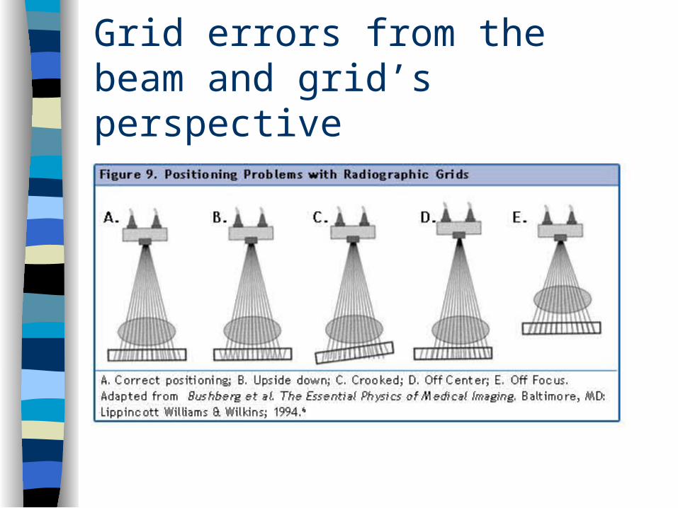
Grid errors from the beam and grid’s perspective
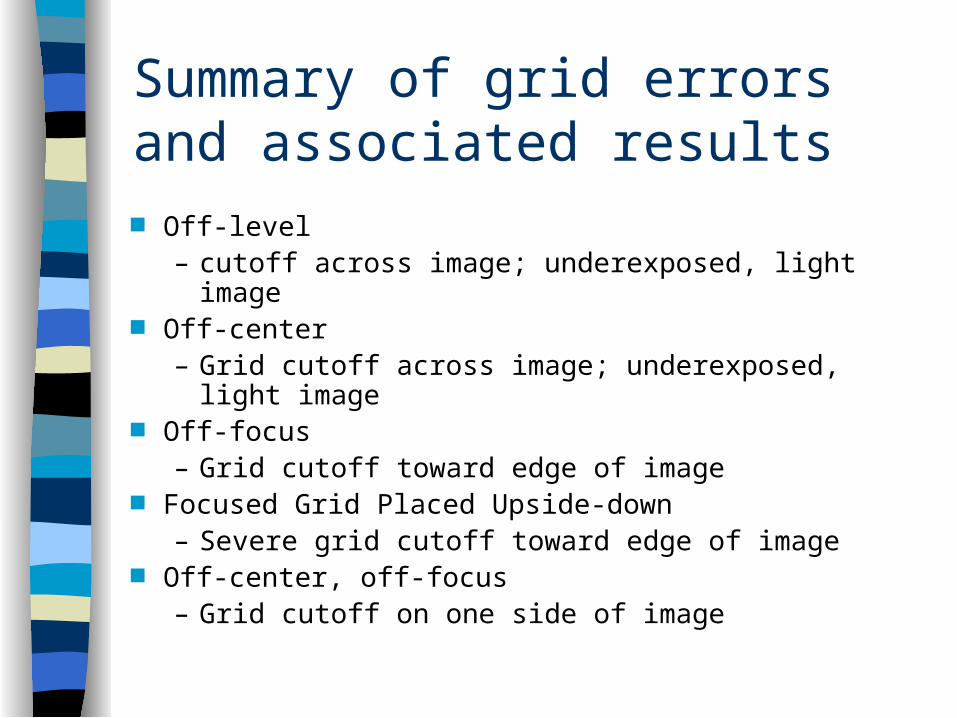
Summary of grid errors and associated results Off-level
– cutoff across image; underexposed, light image Off-center
– Grid cutoff across image; underexposed, light image Off-focus
– Grid cutoff toward edge of image Focused Grid Placed Upside-down
– Severe grid cutoff toward edge of image Off-center, off-focus
– Grid cutoff on one side of image
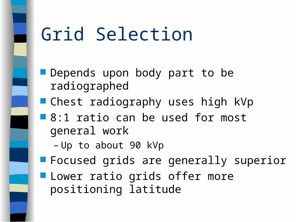
Grid Selection
Depends upon body part to be radiographed
Chest radiography uses high kVp 8:1 ratio can be used for most general work
– Up to about 90 kVp Focused grids are generally superior Lower ratio grids offer more positioning
latitude
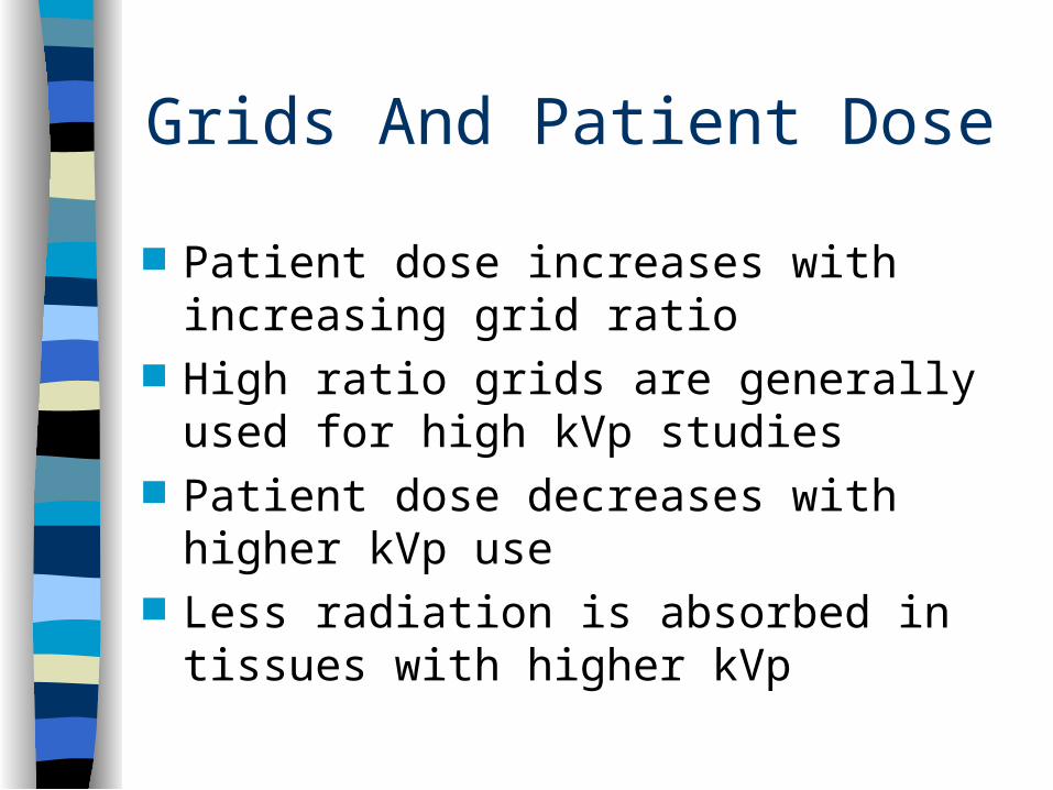
Grids And Patient Dose
Patient dose increases with increasing grid ratio
High ratio grids are generally used for high kVp studies
Patient dose decreases with higher kVp use
Less radiation is absorbed in tissues with higher kVp
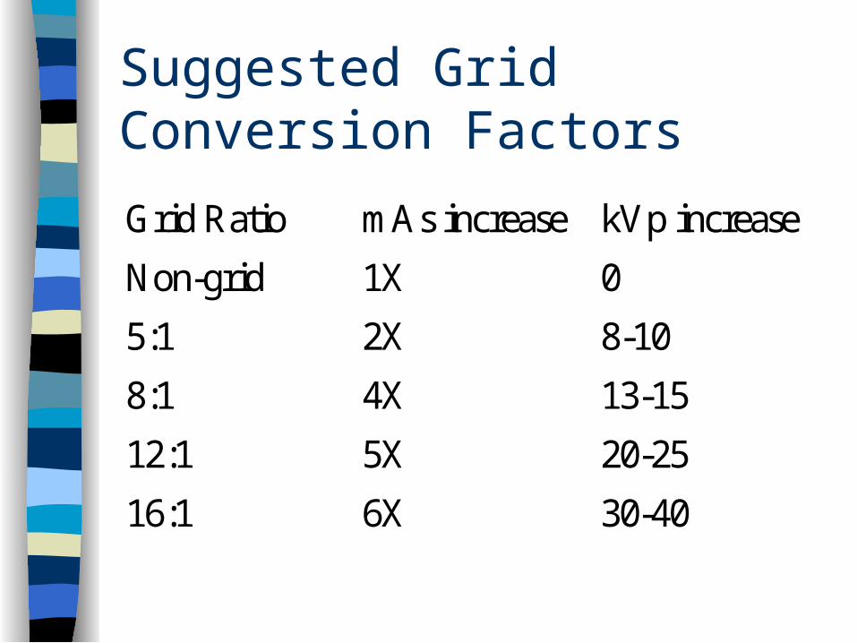
Suggested Grid Conversion Factors
Grid Ratio mAs increase kVp increase
Non-grid 1X 0
5:1 2X 8-10
8:1 4X 13-15
12:1 5X 20-25
16:1 6X 30-40
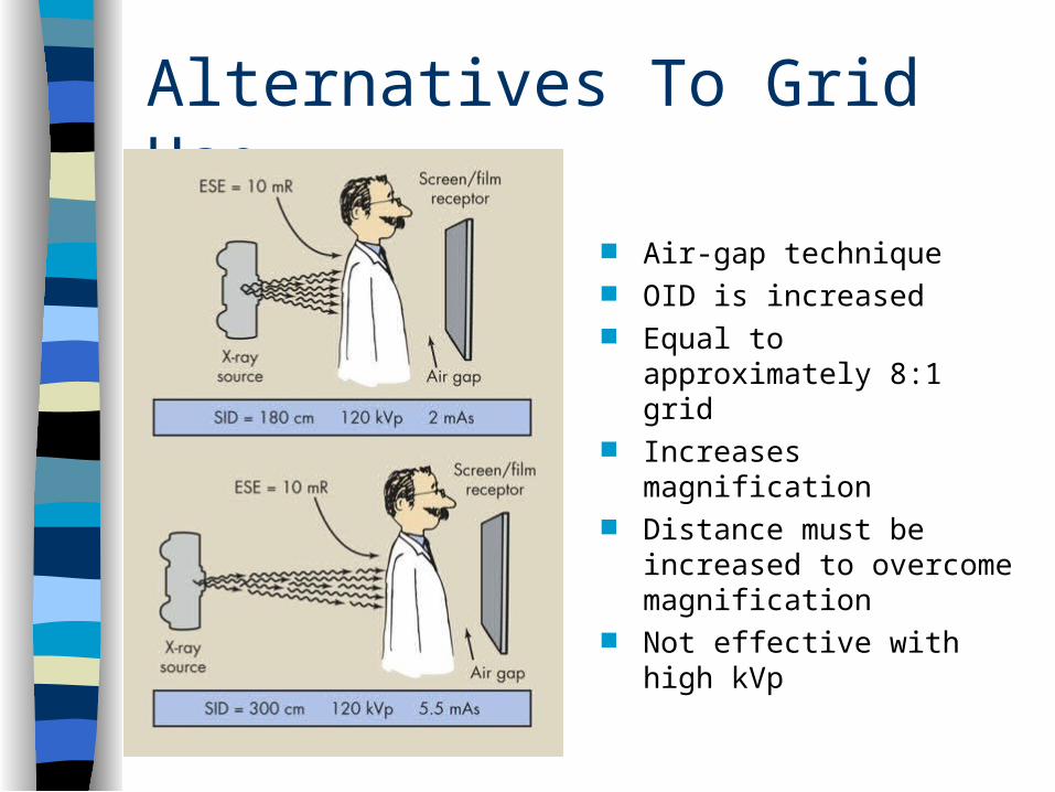
Alternatives To Grid Use
Air-gap technique OID is increased Equal to approximately 8:1
grid Increases magnification Distance must be increased
to overcome magnification Not effective with high kVp