Embed Size (px)
Citation preview
THE HYDROELECTRIC POWER PLANT ENG. SÉRGIOMOTTA (PORTO PRIMAVERA) IN THE PARANÁ RIVER
This paper was prepared by CESP Diretoria de Engenharia e Construção e Divisão Civil - ERC and Gerência de Obras de PortoPrimavera - EEP with the collaboration of CESP: Divisão Eletromecanica - ERE, Departamento de Meio Ambiente - AO, Departamentode Gestão da Produção - OP and the designer THEMAG Engenharia e Gerenciamento Ltda
Main Brazilian Dams III
306
THE HYDROELECTRIC POWER PLANT ENG. SÉRGIOMOTTA (PORTO PRIMAVERA) IN THE PARANÁ RIVER
1. INTRODUCTION
The Hydroelectric Development Eng. Sérgio Motta(Porto Primavera) is a large size power plant belongingto the CESP - Companhia Energética de São Paulo,located at the Southwestern end of the State of SãoPaulo, in the region called the Pontal do Paranapanema.It is situated in the Paraná River, 28 km upstream of itsconfluence with the Paranapanema River and 267 kmdownstream of the Hydroelectric Power Plant Eng. SouzaDias (Jupiá).
The area of implantation of the development comprisesthe regions of the municipalities of Anaurilândia, in theState of Mato Grosso do Sul, and Rosana, in the Stateof São Paulo, 789 km from the capital São Paulo.
The greater part of the area presents a uniform relief,configuring low and ample hills that advance in thedirection of the Paraná River, which has its principalriverbed running beside its left abutment, and an amplefloodplain extending to its right abutment, with widths ofthe order of 10 km.
The location of the dam permitted the connection byhighway between the Northeastern region of the State ofSão Paulo and the State of Mato Grosso do Sul, with a
planned future connection by railroad. The constructionof a navigation lock, located in the the left bank, permittedmaintaining and improving navigation of the Paraná Riverbetween Porto Primavera and Jupiá.
The firm responsible for the project in all its phases(feasibility, basic and executive) was THEMAGEngenharia Ltda.; the main constructor of the civil workswas the firm Construçoes e Comércio Camargo CorreaS/A, and the supplier of the electromechanical equipment,the consortium Consórcio Gipa - Grupamento IndustrialParaná - Paranapanema, whose principal associates werethe firms Alstom Hydro Energia Brasil S.A., Inepar S/AIndústrias e Construções and ABB Ltda.
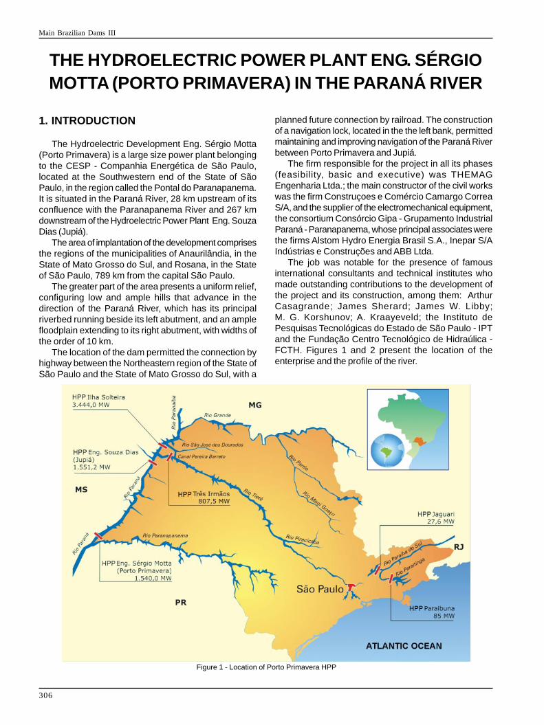
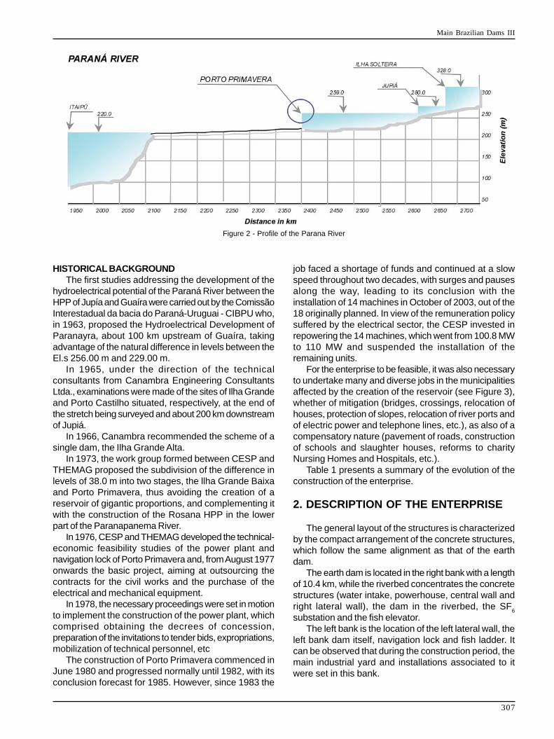
The job was notable for the presence of famousinternational consultants and technical institutes whomade outstanding contributions to the development ofthe project and its construction, among them: ArthurCasagrande; James Sherard; James W. Libby;M. G. Korshunov; A. Kraayeveld; the Instituto dePesquisas Tecnológicas do Estado de São Paulo - IPTand the Fundação Centro Tecnológico de Hidraúlica -FCTH. Figures 1 and 2 present the location of theenterprise and the profile of the river.
Figure 1 - Location of Porto Primavera HPP
Main Brazilian Dams III
307
HISTORICAL BACKGROUNDThe first studies addressing the development of the
hydroelectrical potential of the Paraná River between theHPP of Jupía and Guaíra were carried out by the ComissãoInterestadual da bacia do Paraná-Uruguai - CIBPU who,in 1963, proposed the Hydroelectrical Development ofParanayra, about 100 km upstream of Guaíra, takingadvantage of the natural difference in levels between theEl.s 256.00 m and 229.00 m.
In 1965, under the direction of the technicalconsultants from Canambra Engineering ConsultantsLtda., examinations were made of the sites of Ilha Grandeand Porto Castilho situated, respectively, at the end ofthe stretch being surveyed and about 200 km downstreamof Jupiá.
In 1966, Canambra recommended the scheme of asingle dam, the Ilha Grande Alta.
In 1973, the work group formed between CESP andTHEMAG proposed the subdivision of the difference inlevels of 38.0 m into two stages, the llha Grande Baixaand Porto Primavera, thus avoiding the creation of areservoir of gigantic proportions, and complementing itwith the construction of the Rosana HPP in the lowerpart of the Paranapanema River.
In 1976, CESP and THEMAG developed the technical-economic feasibility studies of the power plant andnavigation lock of Porto Primavera and, from August 1977onwards the basic project, aiming at outsourcing thecontracts for the civil works and the purchase of theelectrical and mechanical equipment.
In 1978, the necessary proceedings were set in motionto implement the construction of the power plant, whichcomprised obtaining the decrees of concession,preparation of the invitations to tender bids, expropriations,mobilization of technical personnel, etc
The construction of Porto Primavera commenced inJune 1980 and progressed normally until 1982, with itsconclusion forecast for 1985. However, since 1983 the
Figure 2 - Profile of the Parana River
job faced a shortage of funds and continued at a slowspeed throughout two decades, with surges and pausesalong the way, leading to its conclusion with theinstallation of 14 machines in October of 2003, out of the18 originally planned. In view of the remuneration policysuffered by the electrical sector, the CESP invested inrepowering the 14 machines, which went from 100.8 MWto 110 MW and suspended the installation of theremaining units.
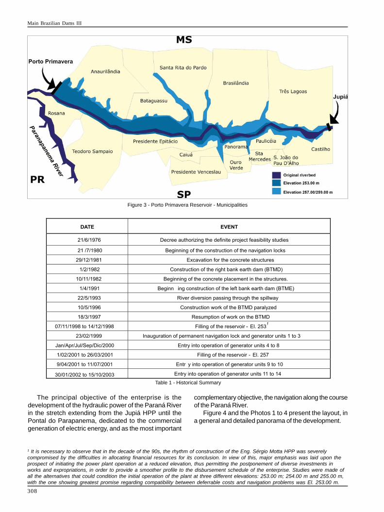
For the enterprise to be feasible, it was also necessaryto undertake many and diverse jobs in the municipalitiesaffected by the creation of the reservoir (see Figure 3),whether of mitigation (bridges, crossings, relocation ofhouses, protection of slopes, relocation of river ports andof electric power and telephone lines, etc.), as also of acompensatory nature (pavement of roads, constructionof schools and slaughter houses, reforms to charityNursing Homes and Hospitals, etc.).
Table 1 presents a summary of the evolution of theconstruction of the enterprise.
2. DESCRIPTION OF THE ENTERPRISE
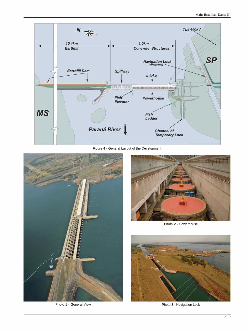
The general layout of the structures is characterizedby the compact arrangement of the concrete structures,which follow the same alignment as that of the earthdam.
The earth dam is located in the right bank with a lengthof 10.4 km, while the riverbed concentrates the concretestructures (water intake, powerhouse, central wall andright lateral wall), the dam in the riverbed, the SF
6
substation and the fish elevator.The left bank is the location of the left lateral wall, the
left bank dam itself, navigation lock and fish ladder. Itcan be observed that during the construction period, themain industrial yard and installations associated to itwere set in this bank.
Main Brazilian Dams III
308
Figure 3 - Porto Primavera Reservoir - Municipalities
1 It is necessary to observe that in the decade of the 90s, the rhythm of construction of the Eng. Sérgio Motta HPP was severelycompromised by the difficulties in allocating financial resources for its conclusion. In view of this, major emphasis was laid upon theprospect of initiating the power plant operation at a reduced elevation, thus permitting the postponement of diverse investments inworks and expropriations, in order to provide a smoother profile to the disbursement schedule of the enterprise. Studies were made ofall the alternatives that could condition the initial operation of the plant at three different elevations: 253.00 m; 254.00 m and 255.00 m,with the one showing greatest promise regarding compatibility between deferrable costs and navigation problems was El. 253.00 m.
The principal objective of the enterprise is thedevelopment of the hydraulic power of the Paraná Riverin the stretch extending from the Jupiá HPP until thePontal do Parapanema, dedicated to the commercialgeneration of electric energy, and as the most important
complementary objective, the navigation along the courseof the Paraná River.
Figure 4 and the Photos 1 to 4 present the layout, ina general and detailed panorama of the development.
Table 1 - Historical Summary
Main Brazilian Dams III
309
Figure 4 - General Layout of the Development
Photo 1 - General View Photo 3 - Navigation Lock
Photo 2 - Powerhouse
Main Brazilian Dams III
310
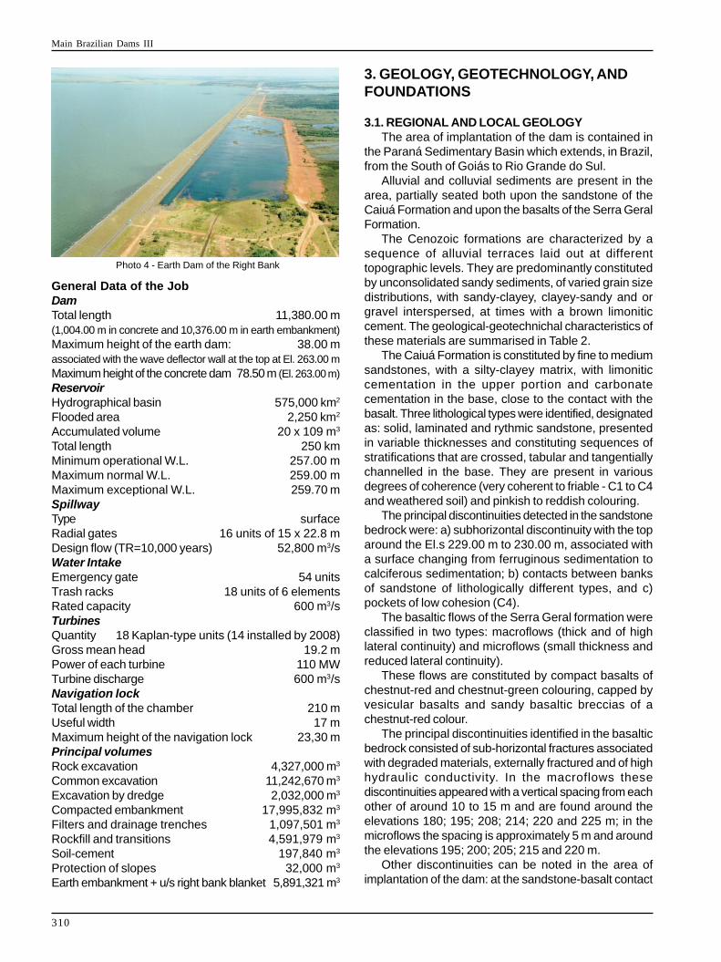
Photo 4 - Earth Dam of the Right Bank
General Data of the JobDamTotal length 11,380.00 m(1,004.00 m in concrete and 10,376.00 m in earth embankment)Maximum height of the earth dam: 38.00 massociated with the wave deflector wall at the top at El. 263.00 mMaximum height of the concrete dam 78.50 m (El. 263.00 m)ReservoirHydrographical basin 575,000 km2
Flooded area 2,250 km2
Accumulated volume 20 x 109 m3
Total length 250 kmMinimum operational W.L. 257.00 mMaximum normal W.L. 259.00 mMaximum exceptional W.L. 259.70 mSpillwayType surfaceRadial gates 16 units of 15 x 22.8 mDesign flow (TR=10,000 years) 52,800 m3/sWater IntakeEmergency gate 54 unitsTrash racks 18 units of 6 elementsRated capacity 600 m3/sTurbinesQuantity 18 Kaplan-type units (14 installed by 2008)Gross mean head 19.2 mPower of each turbine 110 MWTurbine discharge 600 m3/sNavigation lockTotal length of the chamber 210 mUseful width 17 mMaximum height of the navigation lock 23,30 mPrincipal volumesRock excavation 4,327,000 m3
Common excavation 11,242,670 m3
Excavation by dredge 2,032,000 m3
Compacted embankment 17,995,832 m3
Filters and drainage trenches 1,097,501 m3
Rockfill and transitions 4,591,979 m3
Soil-cement 197,840 m3
Protection of slopes 32,000 m3
Earth embankment + u/s right bank blanket 5,891,321 m3
3. GEOLOGY, GEOTECHNOLOGY, ANDFOUNDATIONS
3.1. REGIONAL AND LOCAL GEOLOGYThe area of implantation of the dam is contained in
the Paraná Sedimentary Basin which extends, in Brazil,from the South of Goiás to Rio Grande do Sul.
Alluvial and colluvial sediments are present in thearea, partially seated both upon the sandstone of theCaiuá Formation and upon the basalts of the Serra GeralFormation.
The Cenozoic formations are characterized by asequence of alluvial terraces laid out at differenttopographic levels. They are predominantly constitutedby unconsolidated sandy sediments, of varied grain sizedistributions, with sandy-clayey, clayey-sandy and orgravel interspersed, at times with a brown limoniticcement. The geological-geotechnichal characteristics ofthese materials are summarised in Table 2.
The Caiuá Formation is constituted by fine to mediumsandstones, with a silty-clayey matrix, with limoniticcementation in the upper portion and carbonatecementation in the base, close to the contact with thebasalt. Three lithological types were identified, designatedas: solid, laminated and rythmic sandstone, presentedin variable thicknesses and constituting sequences ofstratifications that are crossed, tabular and tangentiallychannelled in the base. They are present in variousdegrees of coherence (very coherent to friable - C1 to C4and weathered soil) and pinkish to reddish colouring.
The principal discontinuities detected in the sandstonebedrock were: a) subhorizontal discontinuity with the toparound the El.s 229.00 m to 230.00 m, associated witha surface changing from ferruginous sedimentation tocalciferous sedimentation; b) contacts between banksof sandstone of lithologically different types, and c)pockets of low cohesion (C4).
The basaltic flows of the Serra Geral formation wereclassified in two types: macroflows (thick and of highlateral continuity) and microflows (small thickness andreduced lateral continuity).
These flows are constituted by compact basalts ofchestnut-red and chestnut-green colouring, capped byvesicular basalts and sandy basaltic breccias of achestnut-red colour.
The principal discontinuities identified in the basalticbedrock consisted of sub-horizontal fractures associatedwith degraded materials, externally fractured and of highhydraulic conductivity. In the macroflows thesediscontinuities appeared with a vertical spacing from eachother of around 10 to 15 m and are found around theelevations 180; 195; 208; 214; 220 and 225 m; in themicroflows the spacing is approximately 5 m and aroundthe elevations 195; 200; 205; 215 and 220 m.
Other discontinuities can be noted in the area ofimplantation of the dam: at the sandstone-basalt contact
Main Brazilian Dams III
311
and at the contact between the micro and the macroflowsin the neighbourhood of Station 40. They appear withhigh hydraulic conductivity and sometimes fairlyweathered.
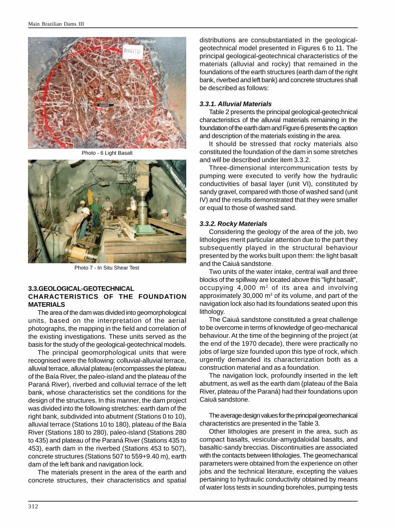
The existence of a peculiar lithology of the basalticflows is notable, characterized by a rock of low densityand strength, being designated in the Project as "lightbasalt" with a mineralogical composition essentiallyformed by expansive clayey-minerals (group of thesmectites and paligorskites). Various occurrences of"light basalt" were detected along the axis of the powerplant, although they only showed high continuity in theregion of the concrete structures.
The occurrence in the area of the concrete structuresis situated in the riverbed, within the limits investigatedpresenting an area of 17.000 m2 and semi-circulardevelopment, and its thickness increases towards thecentre of this occurrence, reaching approximately 18 m.
3.2. GEOTECHNICAL INVESTIGATIONSThe study of the existing materials in the area of the
dam was developed on the basis of the followingelements: satellite images, aerial photography, mappingin the field, prospection through 1,125 rotary drillings,1,857 percussion soundings, 163 auger soundings and42 exploratory pits; tests on-site and in the laboratory.The field tests included: SPT; continuous staticpenetration; vane shear tests; water loss tests; three-dimensional pumping tests to evaluate the hydraulicconductivity of the bedrocks (sandstone and basalt) andof the alluvium; deformability in situ; strength and pulling.The laboratory tests included characterization,deformability; strength, adhesion, tension and shear.
The so-called "light basalt" was specifically subjectedto tests in situ of direct shear, deformability, creep anddilatometry, for which a shaft was excavated in the regionof the permanent navigation lock.
An extensive programme was conducted to evaluatethe behaviour of the breaking of the basalt rock in thearea of the obligatory excavations for the concretestructures with a view to employing these materials forprotection of the slopes of the dam and as concreteaggregate.
Three-dimensional pumping tests were conducted inthe alluvium, at the top of the Caiuá sandstone and inthe fractured basalt which, together with the geological-structural knowledge permitted defining the values ofhydraulic conductivities, their principal directions and theirspecific storage coefficients.
A wide-ranging research programme was alsoconducted on the vegetation cover (grasses) to choosethe most adequate species to protect the downstreamslope between the crest of the dam of the right bank andthe elevation of the roadway.
3.2.1. Execution of the Exploratory Shaft in thePermanent Navigation lock
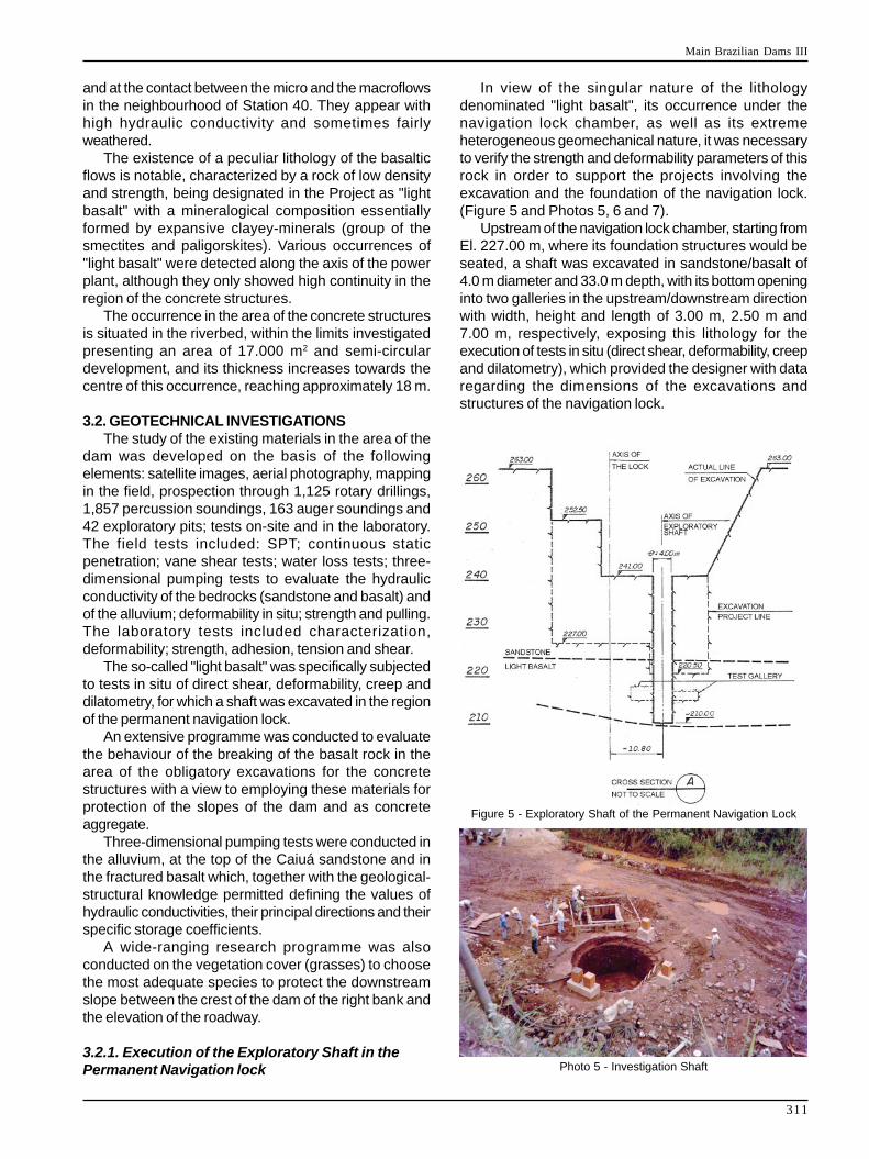
In view of the singular nature of the lithologydenominated "light basalt", its occurrence under thenavigation lock chamber, as well as its extremeheterogeneous geomechanical nature, it was necessaryto verify the strength and deformability parameters of thisrock in order to support the projects involving theexcavation and the foundation of the navigation lock.(Figure 5 and Photos 5, 6 and 7).
Upstream of the navigation lock chamber, starting fromEl. 227.00 m, where its foundation structures would beseated, a shaft was excavated in sandstone/basalt of4.0 m diameter and 33.0 m depth, with its bottom openinginto two galleries in the upstream/downstream directionwith width, height and length of 3.00 m, 2.50 m and7.00 m, respectively, exposing this lithology for theexecution of tests in situ (direct shear, deformability, creepand dilatometry), which provided the designer with dataregarding the dimensions of the excavations andstructures of the navigation lock.
Figure 5 - Exploratory Shaft of the Permanent Navigation Lock
Photo 5 - Investigation Shaft
Main Brazilian Dams III
312
Photo - 6 Light Basalt
Photo 7 - In Situ Shear Test
3.3.GEOLOGICAL-GEOTECHNICALCHARACTERISTICS OF THE FOUNDATIONMATERIALS
The area of the dam was divided into geomorphologicalunits, based on the interpretation of the aerialphotographs, the mapping in the field and correlation ofthe existing investigations. These units served as thebasis for the study of the geological-geotechnical models.
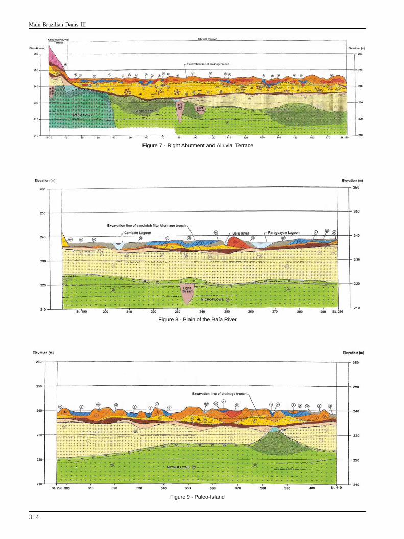
The principal geomorphological units that wererecognised were the following: colluvial-alluvial terrace,alluvial terrace, alluvial plateau (encompasses the plateauof the Baía River, the paleo-island and the plateau of theParaná River), riverbed and colluvial terrace of the leftbank, whose characteristics set the conditions for thedesign of the structures. In this manner, the dam projectwas divided into the following stretches: earth dam of theright bank, subdivided into abutment (Stations 0 to 10),alluvial terrace (Stations 10 to 180), plateau of the BaíaRiver (Stations 180 to 280), paleo-island (Stations 280to 435) and plateau of the Paraná River (Stations 435 to453), earth dam in the riverbed (Stations 453 to 507),concrete structures (Stations 507 to 559+9.40 m), earthdam of the left bank and navigation lock.
The materials present in the area of the earth andconcrete structures, their characteristics and spatial
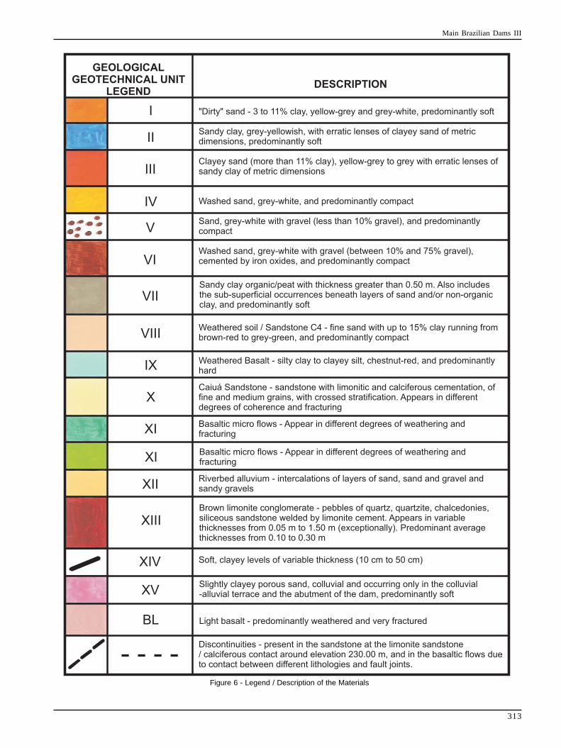
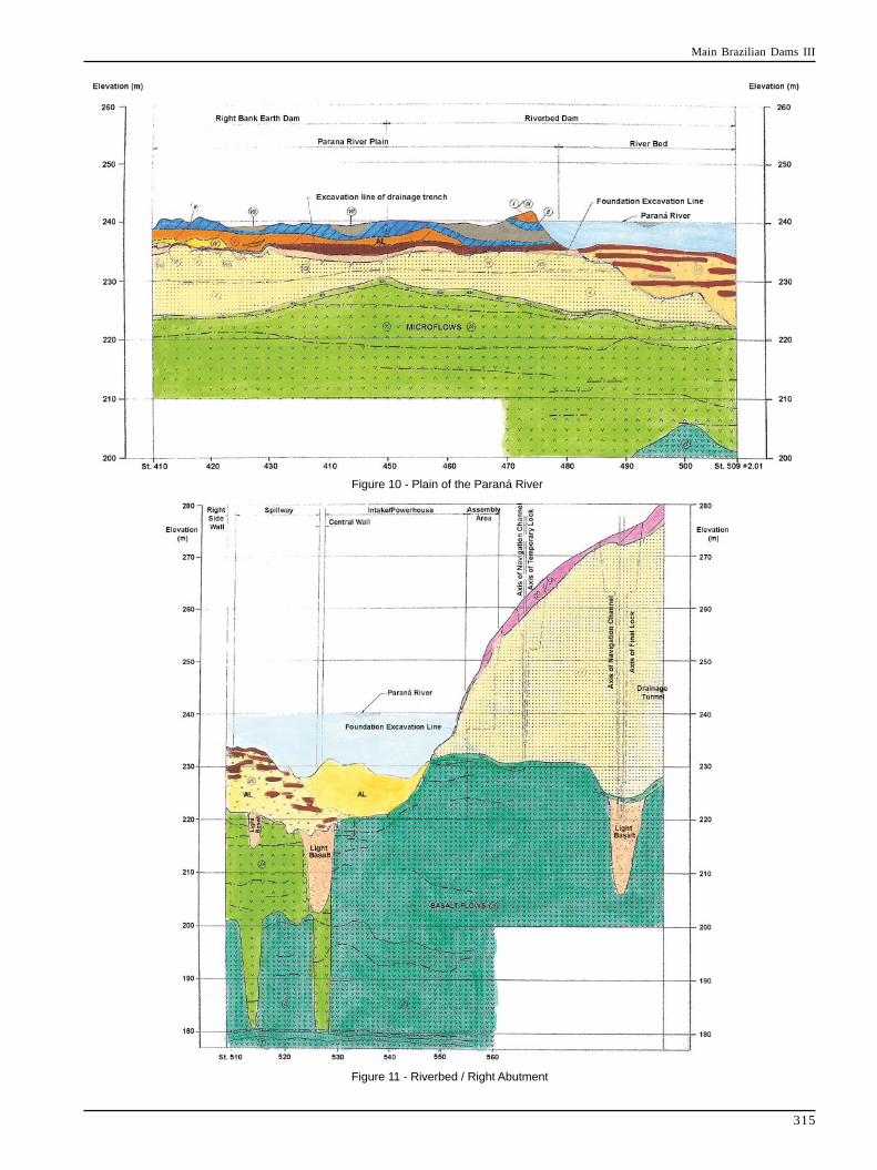
distributions are consubstantiated in the geological-geotechnical model presented in Figures 6 to 11. Theprincipal geological-geotechnical characteristics of thematerials (alluvial and rocky) that remained in thefoundations of the earth structures (earth dam of the rightbank, riverbed and left bank) and concrete structures shallbe described as follows:
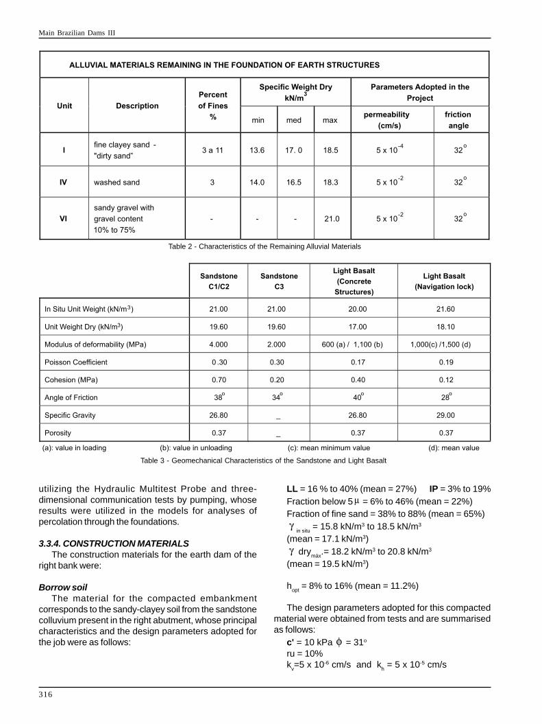
3.3.1. Alluvial MaterialsTable 2 presents the principal geological-geotechnical
characteristics of the alluvial materials remaining in thefoundation of the earth dam and Figure 6 presents the captionand description of the materials existing in the area.
It should be stressed that rocky materials alsoconstituted the foundation of the dam in some stretchesand will be described under item 3.3.2.
Three-dimensional intercommunication tests bypumping were executed to verify how the hydraulicconductivities of basal layer (unit VI), constituted bysandy gravel, compared with those of washed sand (unitIV) and the results demonstrated that they were smalleror equal to those of washed sand.
3.3.2. Rocky MaterialsConsidering the geology of the area of the job, two
lithologies merit particular attention due to the part theysubsequently played in the structural behaviourpresented by the works built upon them: the light basaltand the Caiuá sandstone.
Two units of the water intake, central wall and threeblocks of the spillway are located above this "light basalt",occupying 4,000 m2 of its area and involvingapproximately 30,000 m3 of its volume, and part of thenavigation lock also had its foundations seated upon thislithology.
The Caiuá sandstone constituted a great challengeto be overcome in terms of knowledge of geo-mechanicalbehaviour. At the time of the beginning of the project (atthe end of the 1970 decade), there were practically nojobs of large size founded upon this type of rock, whichurgently demanded its characterization both as aconstruction material and as a foundation.
The navigation lock, profoundly inserted in the leftabutment, as well as the earth dam (plateau of the BaíaRiver, plateau of the Paraná) had their foundations uponCaiuá sandstone.
The average design values for the principal geomechanicalcharacteristics are presented in the Table 3.
Other lithologies are present in the area, such ascompact basalts, vesicular-amygdaloidal basalts, andbasaltic-sandy breccias. Discontinuities are associatedwith the contacts between lithologies. The geomechanicalparameters were obtained from the experience on otherjobs and the technical literature, excepting the valuespertaining to hydraulic conductivity obtained by meansof water loss tests in sounding boreholes, pumping tests
Main Brazilian Dams III
313
Figure 6 - Legend / Description of the Materials
Main Brazilian Dams III
314
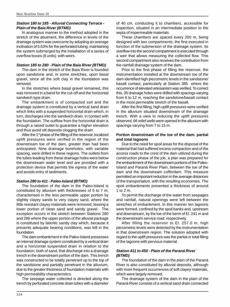
Figure 7 - Right Abutment and Alluvial Terrace
Figure 8 - Plain of the Baía River
Figure 9 - Paleo-Island
Main Brazilian Dams III
315
Figure 10 - Plain of the Paraná River
Figure 11 - Riverbed / Right Abutment
Main Brazilian Dams III
316
utilizing the Hydraulic Multitest Probe and three-dimensional communication tests by pumping, whoseresults were utilized in the models for analyses ofpercolation through the foundations.
3.3.4. CONSTRUCTION MATERIALSThe construction materials for the earth dam of the
right bank were:
Borrow soilThe material for the compacted embankment
corresponds to the sandy-clayey soil from the sandstonecolluvium present in the right abutment, whose principalcharacteristics and the design parameters adopted forthe job were as follows:
LL = 16 % to 40% (mean = 27%) IP = 3% to 19%Fraction below 5 = 6% to 46% (mean = 22%)Fraction of fine sand = 38% to 88% (mean = 65%)
in situ = 15.8 kN/m3 to 18.5 kN/m3
(mean = 17.1 kN/m3)
drymáx
.= 18.2 kN/m3 to 20.8 kN/m3
(mean = 19.5 kN/m3)
hopt
= 8% to 16% (mean = 11.2%)
The design parameters adopted for this compactedmaterial were obtained from tests and are summarisedas follows:
c' = 10 kPa = 31o
ru = 10%k
v=5 x 10⁻⁶ cm/s and k
h = 5 x 10⁻⁵ cm/s
Table 2 - Characteristics of the Remaining Alluvial Materials
Table 3 - Geomechanical Characteristics of the Sandstone and Light Basalt
Main Brazilian Dams III
317
Granular MaterialsThe granular materials (sand for filters, sand with gravel
for transition, gravel for drains) were obtained from dredgedfluvial deposits (the Jazida do Óleo Cru and in the riverbedclose to Aurora Island).
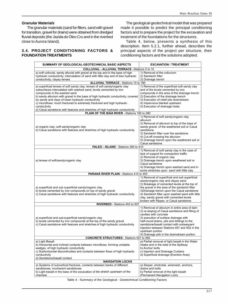
3.4. PROJECT CONDITIONING FACTORS &FOUNDATION TREATMENTS
Table 4 - Summary of the Geological - Geotechnical Conditioning Factors
The geological-geotechnical model that was preparedmade it possible to predict the principal conditioningfactors and to prepare the project for the excavation andtreatment of the foundations for the structures.
Table 4, below, presents a synthesis of thisdescription. Item 5.2.1, further ahead, describes theprincipal aspects of the project per structure, theirconditioning factors and the solutions adopted.
Main Brazilian Dams III
318
4. HYDROLOGY, HYDRAULICS ANDENERGY STUDIES
The development is located in the high Paranáhydrographical basin and is characterized by being thelast hydroelectric project of the Paraná River in the Stateof São Paulo. This river is formed by the confluence ofthe Paranaíba and Grande rivers. In the stretch inquestion, it is a tableland river and its most importanttributaries are the Tietê, Sucuriú, Verde, Peixe andParanapanema.
The hydrological regime of the watercourses in theregion is conditioned by the summer rains, with the floodperiod beginning in December and maximum floodsoccurring in March.
Due to the great extension of the high Paraná basinand the appreciable variations in the elevations that occurwithin it, the region presents great climatic variations fromhumid tropical to temperate. Prior to the phase of theproject, the area of the reservoir, with a predominantlysub-humid climate, presented the following data:• Mean annual temperature = 22 º C• Extreme temperatures = 37.8 º C absolute maximum(March) and 1 º C absolute minimum (May)• Mean annual precipitation = 1,250 mm• Average number of rainy days per year = 82• Predominant wind (permanence) = NE
The following data were considered in the study ofthe floods for the project:• Mean long term flood = 18,500 m3/s• Maximum mean daily flow = 30,670 m3/s• Minimum mean daily flow = 2,579 m3/s• Annual mean flow = 6,602 m3/s
The 1st phase of the diversion occurred in December1981 through the riverbed and the 2nd phase in May 1983through the spillway.
The design flows taken into consideration were thefollowing:• Probable Maximum Flood PMF: 62,000 m3/s• Ten thousand year flood: 45,000 m3/s• Diversion flow of the 2nd phase with a time of recurrenceof 100 years: 34,100 m3/s
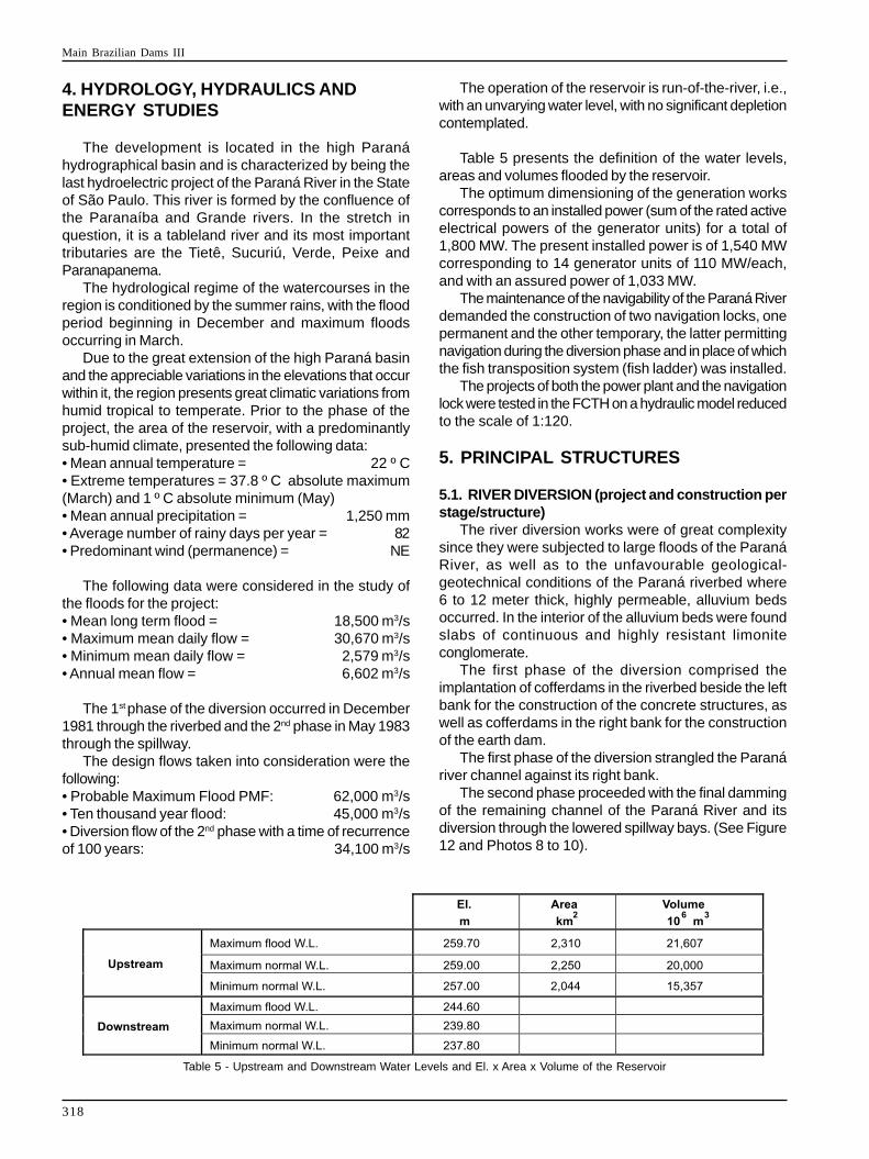
The operation of the reservoir is run-of-the-river, i.e.,with an unvarying water level, with no significant depletioncontemplated.
Table 5 presents the definition of the water levels,areas and volumes flooded by the reservoir.
The optimum dimensioning of the generation workscorresponds to an installed power (sum of the rated activeelectrical powers of the generator units) for a total of1,800 MW. The present installed power is of 1,540 MWcorresponding to 14 generator units of 110 MW/each,and with an assured power of 1,033 MW.
The maintenance of the navigability of the Paraná Riverdemanded the construction of two navigation locks, onepermanent and the other temporary, the latter permittingnavigation during the diversion phase and in place of whichthe fish transposition system (fish ladder) was installed.
The projects of both the power plant and the navigationlock were tested in the FCTH on a hydraulic model reducedto the scale of 1:120.
5. PRINCIPAL STRUCTURES
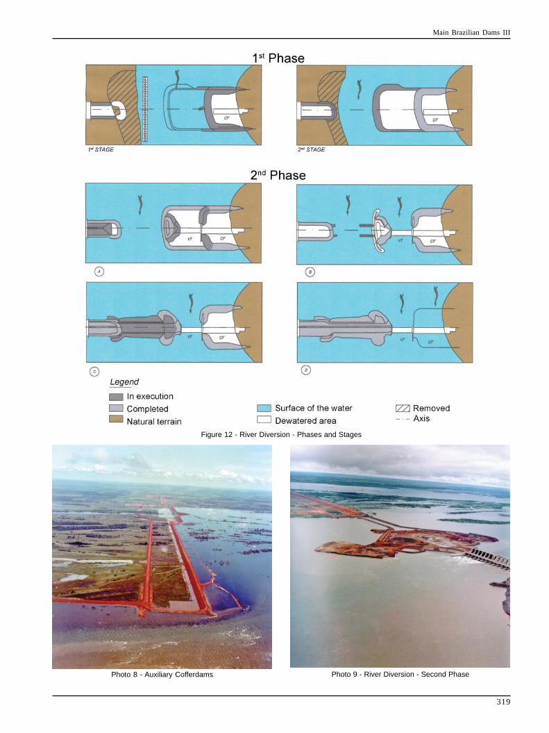
5.1. RIVER DIVERSION (project and construction perstage/structure)
The river diversion works were of great complexitysince they were subjected to large floods of the ParanáRiver, as well as to the unfavourable geological-geotechnical conditions of the Paraná riverbed where6 to 12 meter thick, highly permeable, alluvium bedsoccurred. In the interior of the alluvium beds were foundslabs of continuous and highly resistant limoniteconglomerate.
The first phase of the diversion comprised theimplantation of cofferdams in the riverbed beside the leftbank for the construction of the concrete structures, aswell as cofferdams in the right bank for the constructionof the earth dam.
The first phase of the diversion strangled the Paranáriver channel against its right bank.
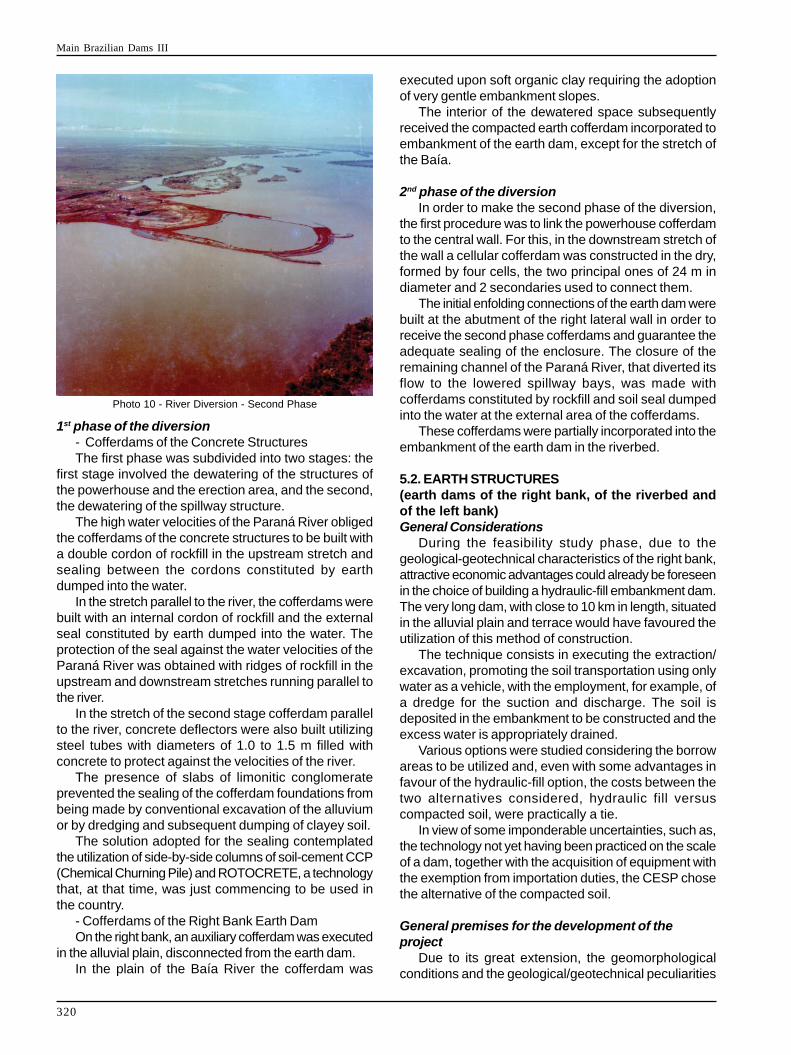
The second phase proceeded with the final dammingof the remaining channel of the Paraná River and itsdiversion through the lowered spillway bays. (See Figure12 and Photos 8 to 10).
Table 5 - Upstream and Downstream Water Levels and El. x Area x Volume of the Reservoir
Main Brazilian Dams III
319
Figure 12 - River Diversion - Phases and Stages
Photo 9 - River Diversion - Second PhasePhoto 8 - Auxiliary Cofferdams
Main Brazilian Dams III
320
1st phase of the diversion- Cofferdams of the Concrete StructuresThe first phase was subdivided into two stages: the
first stage involved the dewatering of the structures ofthe powerhouse and the erection area, and the second,the dewatering of the spillway structure.
The high water velocities of the Paraná River obligedthe cofferdams of the concrete structures to be built witha double cordon of rockfill in the upstream stretch andsealing between the cordons constituted by earthdumped into the water.
In the stretch parallel to the river, the cofferdams werebuilt with an internal cordon of rockfill and the externalseal constituted by earth dumped into the water. Theprotection of the seal against the water velocities of theParaná River was obtained with ridges of rockfill in theupstream and downstream stretches running parallel tothe river.
In the stretch of the second stage cofferdam parallelto the river, concrete deflectors were also built utilizingsteel tubes with diameters of 1.0 to 1.5 m filled withconcrete to protect against the velocities of the river.
The presence of slabs of limonitic conglomerateprevented the sealing of the cofferdam foundations frombeing made by conventional excavation of the alluviumor by dredging and subsequent dumping of clayey soil.
The solution adopted for the sealing contemplatedthe utilization of side-by-side columns of soil-cement CCP(Chemical Churning Pile) and ROTOCRETE, a technologythat, at that time, was just commencing to be used inthe country.
- Cofferdams of the Right Bank Earth DamOn the right bank, an auxiliary cofferdam was executed
in the alluvial plain, disconnected from the earth dam.In the plain of the Baía River the cofferdam was
executed upon soft organic clay requiring the adoptionof very gentle embankment slopes.
The interior of the dewatered space subsequentlyreceived the compacted earth cofferdam incorporated toembankment of the earth dam, except for the stretch ofthe Baía.
2nd phase of the diversionIn order to make the second phase of the diversion,
the first procedure was to link the powerhouse cofferdamto the central wall. For this, in the downstream stretch ofthe wall a cellular cofferdam was constructed in the dry,formed by four cells, the two principal ones of 24 m indiameter and 2 secondaries used to connect them.
The initial enfolding connections of the earth dam werebuilt at the abutment of the right lateral wall in order toreceive the second phase cofferdams and guarantee theadequate sealing of the enclosure. The closure of theremaining channel of the Paraná River, that diverted itsflow to the lowered spillway bays, was made withcofferdams constituted by rockfill and soil seal dumpedinto the water at the external area of the cofferdams.
These cofferdams were partially incorporated into theembankment of the earth dam in the riverbed.
5.2. EARTH STRUCTURES(earth dams of the right bank, of the riverbed andof the left bank)General Considerations
During the feasibility study phase, due to thegeological-geotechnical characteristics of the right bank,attractive economic advantages could already be foreseenin the choice of building a hydraulic-fill embankment dam.The very long dam, with close to 10 km in length, situatedin the alluvial plain and terrace would have favoured theutilization of this method of construction.
The technique consists in executing the extraction/excavation, promoting the soil transportation using onlywater as a vehicle, with the employment, for example, ofa dredge for the suction and discharge. The soil isdeposited in the embankment to be constructed and theexcess water is appropriately drained.
Various options were studied considering the borrowareas to be utilized and, even with some advantages infavour of the hydraulic-fill option, the costs between thetwo alternatives considered, hydraulic fill versuscompacted soil, were practically a tie.
In view of some imponderable uncertainties, such as,the technology not yet having been practiced on the scaleof a dam, together with the acquisition of equipment withthe exemption from importation duties, the CESP chosethe alternative of the compacted soil.
General premises for the development of theproject
Due to its great extension, the geomorphologicalconditions and the geological/geotechnical peculiarities
Photo 10 - River Diversion - Second Phase
Main Brazilian Dams III
321
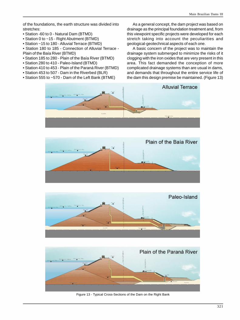
of the foundations, the earth structure was divided intostretches:• Station -60 to 0 - Natural Dam (BTMD)• Station 0 to ~15 - Right Abutment (BTMD)• Station ~15 to 180 - Alluvial Terrace (BTMD)• Station 180 to 185 - Connection of Alluvial Terrace -Plain of the Baía River (BTMD)• Station 185 to 280 - Plain of the Baía River (BTMD)• Station 280 to 410 - Paleo-Island (BTMD)• Station 410 to 453 - Plain of the Paraná River (BTMD)• Station 453 to 507 - Dam in the Riverbed (BLR)• Station 555 to ~570 - Dam of the Left Bank (BTME)
As a general concept, the dam project was based ondrainage as the principal foundation treatment and, fromthis viewpoint specific projects were developed for eachstretch taking into account the peculiarities andgeological-geotechnical aspects of each one.
A basic concern of the project was to maintain thedrainage system submerged to minimize the risks of itclogging with the iron oxides that are very present in thisarea. This fact demanded the conception of morecomplicated drainage systems than are usual in dams,and demands that throughout the entire service life ofthe dam this design premise be maintained. (Figure 13)
Figure 13 - Typical Cross-Sections of the Dam on the Right Bank
Main Brazilian Dams III
322
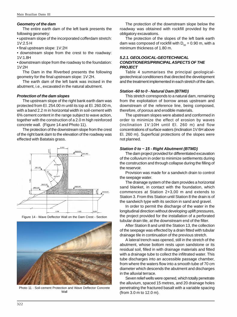
Figure 14 - Wave Deflector Wall on the Dam Crest - Section
Photo 11 - Soil-cement Protection and Wave Deflector ConcreteWall
Geometry of the damThe entire earth dam of the left bank presents the
following geometry:• upstream slope of the incorporated cofferdam stretch:1V:2.5 H• final upstream slope: 1V:2H• downstream slope from the crest to the roadway:1V:1.8H• downstream slope from the roadway to the foundation:1V:2H
The Dam in the Riverbed presents the followinggeometry for the final upstream slope: 1V:2H.
The earth dam of the left bank was incised in theabutment, i.e., excavated in the natural abutment.
Protection of the dam slopesThe upstream slope of the right bank earth dam was
protected from El. 254.00 m until its top at El. 260.00 m,with a band 2.2 m in horizontal width in soil-cement with6% cement content in the range subject to wave action,together with the construction of a 2.0 m high reinforcedconcrete wall. (Figure 14 and Photo 11).
The protection of the downstream slope from the crestof the right bank dam to the elevation of the roadway waseffected with Batatais grass.
The protection of the downstream slope below theroadway was obtained with rockfill provided by theobligatory excavations.
The protection of the slopes of the left bank earthdam was composed of rockfill with D
50 = 0.90 m, with a
minimum thickness of 1.80 m.
5.2.1. GEOLOGICAL-GEOTECHNICALCONDITIONERS/PRINCIPAL ASPECTS OF THEPROJECT
Table 4 summarises the principal geological-geotechnical conditioners that directed the developmentand the treatment implemented in each stretch of the dam.
Station -60 to 0 - Natural Dam (BTMD)This stretch corresponds to a natural dam, remaining
from the exploitation of borrow areas upstream anddownstream of the reference line, being composed,therefore, of porous and erodible materials.
The upstream slopes were abated and conformed inorder to minimize the effect of erosion by waves(inclination 1V:10H until El. 260 m) and flowconcentrations of surface waters (inclination 1V:6H aboveEl. 260 m). Superficial protections of the slopes werenot planned.
Station 0 to ~ 15 - Right Abutment (BTMD)The dam project provided for differentiated excavation
of the colluvium in order to minimize settlements duringthe construction and through collapse during the filling ofthe reservoir.
Provision was made for a sandwich drain to controlthe seepage water.
The drainage system of the dam provides a horizontalsand blanket, in contact with the foundation, whichcommences at Station 2+3,00 m and extends toStation 3. From this Station until Station 8 the drain is ofthe sandwich type with its section in sand and gravel.
In order to permit the discharge of the water in thelongitudinal direction without developing uplift pressures,the project provided for the installation of a perforatedtubular drain tile, at the downstream end of the filter.
After Station 8 and until the Station 13, the collectionof the seepage was effected by a drain fitted with tubulardrainage tile in continuation of the previous stretch.
A lateral trench was opened, still in the stretch of theabutment, whose bottom rests upon sandstone or itsresidual soil, filled in with drainage materials and fittedwith a drainage tube to collect the infiltrated water. Thistube discharges into an accessible passage chamber,from where the waters flow into a smooth tube of 70 cmdiameter which descends the abutment and dischargesin the alluvial terrace.
Seven relief wells were opened, which totally penetratethe alluvium, spaced 15 metres, and 20 drainage holespenetrating the fractured basalt with a variable spacing(from 3.0 m to 12.0 m).
Main Brazilian Dams III
323
Station ~15 to 180 - Alluvial Terrace (BTMD)The dam in the alluvial terrace is of the homogeneous
type in compacted soil fitted with a drainage blanket ofsoil located upstream.
The internal drainage system is of the homogeneoustype composed by a vertical sand filter and a suspendedhorizontal filter, also in sand, which discharges into adrainage trench which, in addition to receiving the waterof this system, is the principal control element of thewater seeping through the foundation. The compactedembankment is seated upon an alluvial package with anaverage thickness of around 12 m, with only the materialsof low shear strength and/or very deformable consistency,having been removed from the foundation.
Downstream of the trench, a line of relief wells wasexecuted, spaced 15 m.
After the first phase of the reservoir filling, upliftpressures were verified in the alluvium surpassing thoseinitially expected, leading to the execution of a line ofdrainage holes in the most permeable stretch of thebasalt, spaced from 6 to 12 m downstream of the dam,from the Station 10+16 to the Station 30.
The adoption of the suspended horizontal filterpermitted an increase in the seepage path and aconsequent reduction of the average gradient through thefoundation.
Drainage Downstream of the Alluvial TerraceThe project of the dam of the right bank has its principal
control and safety feature based on a straightforward andeffective drain downstream. The downstream stretch ofthe dam is extremely flat and tends to store rainwatertemporarily that, together with the high water table, hasthe potential to transform stretches of the region intopools.
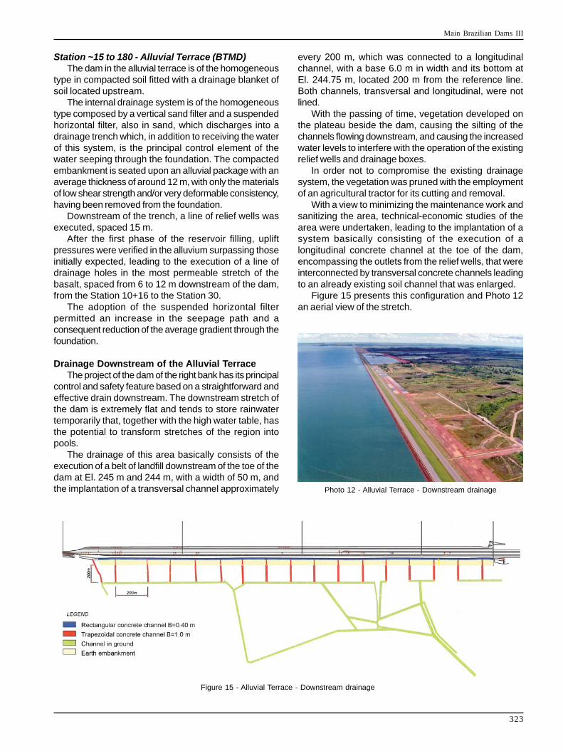
The drainage of this area basically consists of theexecution of a belt of landfill downstream of the toe of thedam at El. 245 m and 244 m, with a width of 50 m, andthe implantation of a transversal channel approximately
every 200 m, which was connected to a longitudinalchannel, with a base 6.0 m in width and its bottom atEl. 244.75 m, located 200 m from the reference line.Both channels, transversal and longitudinal, were notlined.
With the passing of time, vegetation developed onthe plateau beside the dam, causing the silting of thechannels flowing downstream, and causing the increasedwater levels to interfere with the operation of the existingrelief wells and drainage boxes.
In order not to compromise the existing drainagesystem, the vegetation was pruned with the employmentof an agricultural tractor for its cutting and removal.
With a view to minimizing the maintenance work andsanitizing the area, technical-economic studies of thearea were undertaken, leading to the implantation of asystem basically consisting of the execution of alongitudinal concrete channel at the toe of the dam,encompassing the outlets from the relief wells, that wereinterconnected by transversal concrete channels leadingto an already existing soil channel that was enlarged.
Figure 15 presents this configuration and Photo 12an aerial view of the stretch.
Figure 15 - Alluvial Terrace - Downstream drainage
Photo 12 - Alluvial Terrace - Downstream drainage
Main Brazilian Dams III
324
Station 180 to 185 - Alluvial Connecting Terrace -Plain of the Baía River (BTMD)
In analogous manner to the method adopted in thestretch of the abutment, the difference in levels of thedrainage system was overcome by adopting an averageinclination of 5.63% for the perforated tubing, maintainingthe system submerged by the installation of a series ofoverflow boxes (8 units) with weirs.
Station 185 to 280 - Plain of the Baía River (BTMD)The dam in the stretch of the Baía River is founded
upon sandstone and, in some stretches, upon basalgravel, since all the soft clay in the foundation wasremoved.
In the stretches where basal gravel remained, thiswas removed in a band for the cut-off and the horizontalsandwich type drain.
The embankment is of compacted soil and thedrainage system is constituted by a vertical sand drainwhich links with a suspended horizontal drain which, inturn, discharges into the sandwich drain, in contact withthe foundation. The outflow from the horizontal drain isthrough a raised outlet to guarantee a higher elevationand thus avoid silt deposits clogging the drain.
After the 1st phase of the filling of the reservoir, localizeduplift pressures were verified in the region of thedownstream toe of the dam, greater than had beenanticipated. Nine drainage boreholes, with variablespacing, were drilled in these regions. The outlets fromthe tubes leading from these drainage holes were belowthe downstream water level and are provided with aprotection device that permits the egress of the waterand avoids entry of sediments.
Station 280 to 411 - Paleo-Island (BTMD)The foundation of the dam in the Paleo-Island is
constituted by alluvium with thicknesses of 5 to 7 m,characterised in the less permeable upper portion byslightly clayey sands to very clayey sand, where thelittle resistant clayey materials were removed, leaving alower portion of clean sand and sandy gravel. Theexception occurs in the stretch between Stations 280and 296 where the upper portion of the alluvial packageis constituted by lateritic sandy clay which, because itpresents adequate bearing conditions, was left in thefoundation.
The dam embankment in the Paleo-Island possessesan internal drainage system constituted by a vertical drainand a horizontal suspended drain in relation to thefoundation, both of sand, that discharge into a drainagetrench in the downstream portion of the dam. This trenchwas constructed to be totally penetrant up to the top ofthe sandstone and partially penetrant in the alluvium,due to the greater thickness of foundation materials withhigh permeability characteristics.
The seepage water collected is directed along thetrench by perforated concrete drain tubes with a diameter
of 40 cm, conducting it to chambers, accessible forinspection, situated in an intermediate position to thesepta of impermeable materials.
These chambers are spaced every 200 m, beingdesigned with two compartments; the first executed infunction of the submersion of the drainage system. Itsoverflow into the second compartment is executed througha weir that allows measuring the collected flow. Thissecond compartment also receives the contribution fromthe rainfall drainage system of the dam.
Prior to the first phase of filling the reservoir, theinstrumentation installed at the downstream toe of thedam identified high piezometric levels in the sandstone/basalt contact, particularly at Station 385 where theoccurrence of elevated artesianism was verified. To correctthis, 35 drainage holes were drilled with spacings varyingfrom 6 to 12 m, reaching the sandstone/basalt contactin the most permeable stretch of the basalt.
After the first filling, high uplift pressures were verifiedin the alluvium situated downstream of the drainagetrench. With a view to reducing the uplift pressuresobserved, 66 relief wells were opened in the alluvium withspacings varying from 7 to 15 m.
Portion downstream of the toe of the dam: partialand total lagoons
Due to the need for spoil areas for the disposal of thematerial that had suffered excess compaction and of theaccess roads to the crest of the dam utilized during theconstruction phase of the job, a plan was prepared forthe embankment of the downstream portions of the Paleo-Island and Paraná River Plain, between the toe of thedam and the downstream cofferdam. This measurepermitted an important reduction in the average distancesof the transportation, with the resulting economies. Thespoil embankments presented a thickness of around1 to 2 m.
To permit the discharge of the water from seepagesand rainfall, natural openings were left between thestretches of embankment. In this manner ten lagoonswere formed, confined by the spoil banks and, upstreamand downstream, by the toe of the berm of El. 241 m andthe downstream service road, respectively.
After filling the reservoir to El. 257.0 m, highpiezometric levels were detected by the instrumentationin that downstream region. The solution adopted withregard to the uplift pressures was the partial or total fillingof the lagoons with pervious material.
Station 411 to 450 - Plain of the Paraná River(BTMD)
The foundation of the dam in the plain of the ParanáRiver is also constituted by alluvial deposits, althoughwith more frequent occurrences of soft clayey materials,which were largely removed.
The drainage system of the dam in the plain of theParaná River consists of a vertical sand drain connected
Main Brazilian Dams III
325
to a suspended horizontal drain discharging into asandwich drain in contact with the basal sandstone and/or gravel of the foundation. This drain is linked to adrainage trench that penetrates totally to the top of thesandstone.
After the end of the first reservoir filling, 16 drainageholes were executed with a spacing of 24 m, applyingthe same methodology as at the Paleo-Island, and withthe aim of reducing the piezometric pressures in thesandstone/basalt contact and in the more permeablefeatures of the sandstone.
Station 450 to 507 - Dam in the Riverbed (BLR)The area in which the dam in the riverbed is located
presents different characteristics in relation to the alluvialsediments, since part of the dam was implanted in thealluvial plateau of the Paraná River and part in the riverbed.
The River Paraná plain is characterised by plasticand organic clayey sediments, fine sands and sand withgravel at the base between Stations 410 and 475. Theriverbed between Stations 475 and 550 presentsessentially sandy material associated with gravels andconglomeratic layers.
All the alluvial material was excavated for theconstruction of the dam which was totally seated onsandstone. Different typical sections of the dam wereadopted along the stretch in function of the incorporation,or not, of the existing cofferdam.
The stretches of the Stations 450 to 457 and 477 to500 were executed in a homogeneous section, onlyincorporating the upstream rockfill pre-cofferdam, with avertical/inclined drain and a horizontal sandwich typedrain seated upon rock.
In the stretch between the Stations 457 and 477, theupstream and downstream cofferdams were incorporated,adopting an internal drainage analogous to the previousstretch.
After the first phase of the filling and due to the highuplift pressures verified, 52 drainage holes were executedand 2 pumping wells.
Station 555 to ~ 570 - Dam of the Left Bank (BTME)Despite its small extension, various interferences
conditioned the project, among which were: the roadwayand access system, the fish ladder, the provisionalnavigation lock and the left abutment.
The peculiar aspects existing in this stretch are thefollowing:• Horizontal drainage blanket under the downstreamslope.• The temporary navigation lock was banked with sandfrom the spoil area and at the base of this embankmenta sandwich drain was executed, in the interior of whichwere installed two perforated cast iron tubes.• The left abutment, which corresponds to the left slopeof the provisional navigation lock, was protected with
rockfill on a band of about 120 m long upstream of theconnection with the dam.
The protection of the slopes was composed by rockfillwith D
50 = 0,90 m with a minimum thickness of 1.80 m.
The rockfill protection commenced at El. 254.00 m andextended to the crest elevation of this stretch of the dam(263.00 m). The studies carried out indicated no need forthe implantation of a wave deflector on condition that theprotection of the slope was executed with rockfill.
5.3. CONCRETE STRUCTURES(Spillway, Water Intake, Powerhouse, Erection Area,Command Building, Navigation Lock)General
The principal conditioning factors guiding the designof the structures were: the "light basalt"; contactsbetween horizontal and inclined microflows formingunstable wedges of high hydraulic conductivity, sub-horizontal discontinuities and contacts between flows ofhigh hydraulic conductivity.
The project provided for the partial removal of the "lightbasalt" in the area of the water intake and its total removalin the area of the spillway, anchor bolts and a groutinjection and drainage curtain bypassing the upstreamstretch and the sides of the water intake/spillwayassembly and the sidewalls.
The grout curtain constituted by 3 lines of injectioninclined towards upstream (12°, 8° and 4° of inclination)with holes separated 3.0 m from each other inintermediate positions between the rows, reached thefinal elevation of 185.00 m.
The drainage curtain executed to El. 200.00 m isinclined 13º downstream with holes of ø 3" spaced at1.5 m intervals.
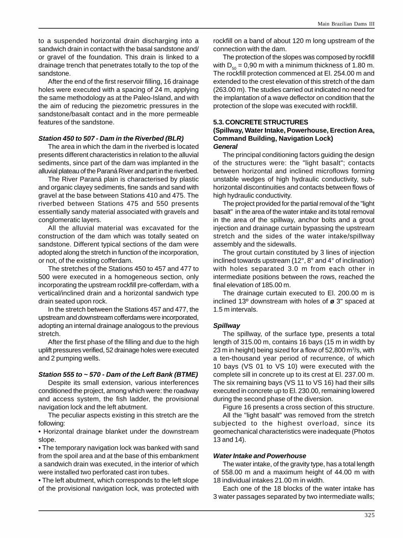
SpillwayThe spillway, of the surface type, presents a total
length of 315.00 m, contains 16 bays (15 m in width by23 m in height) being sized for a flow of 52,800 m3/s, witha ten-thousand year period of recurrence, of which10 bays (VS 01 to VS 10) were executed with thecomplete sill in concrete up to its crest at El. 237.00 m.The six remaining bays (VS 11 to VS 16) had their sillsexecuted in concrete up to El. 230.00, remaining loweredduring the second phase of the diversion.
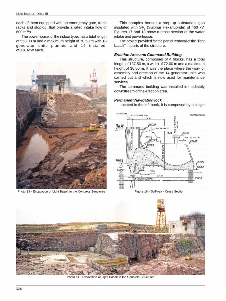
Figure 16 presents a cross section of this structure.All the "light basalt" was removed from the stretch
subjected to the highest overload, since itsgeomechanical characteristics were inadequate (Photos13 and 14).
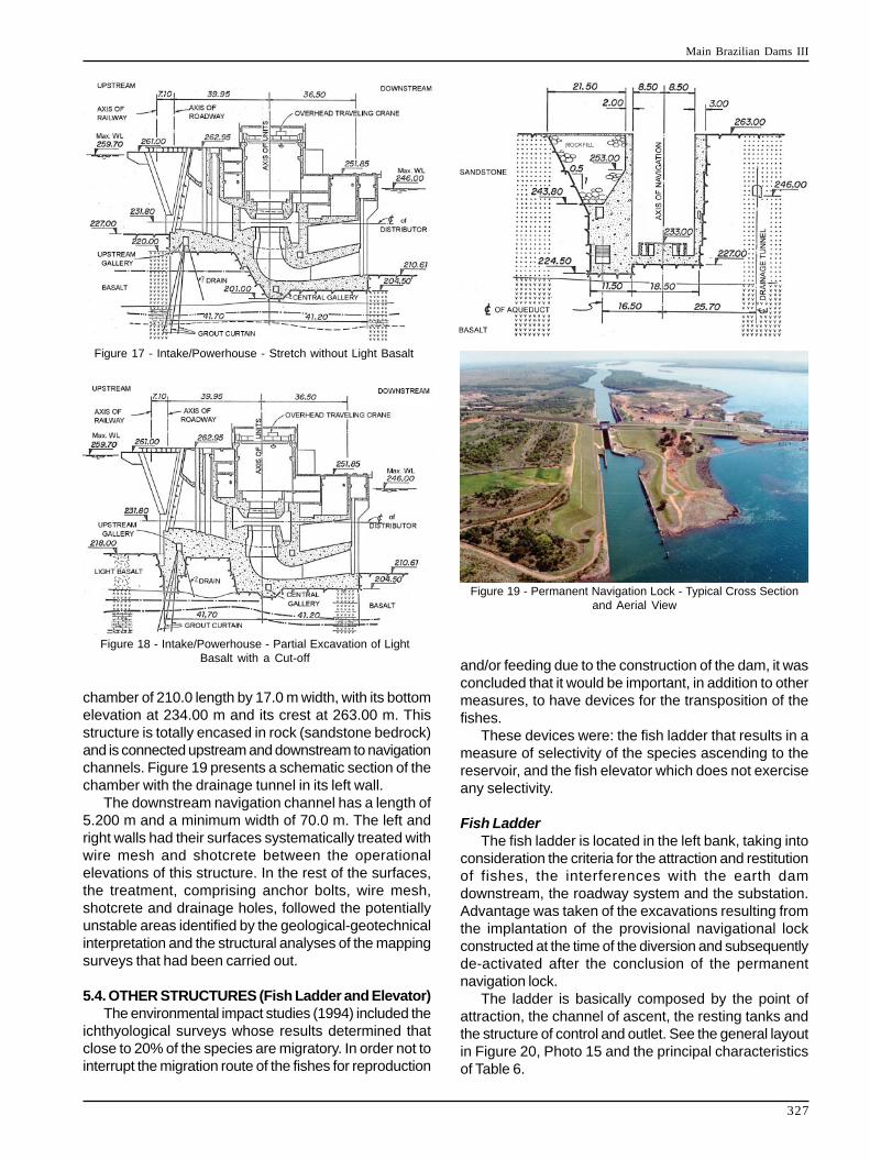
Water Intake and PowerhouseThe water intake, of the gravity type, has a total length
of 558.00 m and a maximum height of 44.00 m with18 individual intakes 21.00 m in width.
Each one of the 18 blocks of the water intake has3 water passages separated by two intermediate walls;
Main Brazilian Dams III
326
Photo 13 - Excavation of Light Basalt in the Concrete Structures
Photo 14 - Excavation of Light Basalt in the Concrete Structures
Figure 16 - Spillway - Cross Section
each of them equipped with an emergency gate, trashracks and stoplog, that provide a rated intake flow of600 m3/s.
The powerhouse, of the indoor type, has a total lengthof 558.00 m and a maximum height of 70.50 m with 18generator units planned and 14 installed,of 110 MW each.
This complex houses a step-up substation, gasinsulated with SF
6 (Sulphur Hexafluoride) of 460 kV.
Figures 17 and 18 show a cross section of the waterintake and powerhouse.
The project provided for the partial removal of the "lightbasalt" in parts of the structure.
Erection Area and Command BuildingThis structure, composed of 4 blocks, has a total
length of 137.50 m, a width of 72.00 m and a maximumheight of 36.50 m. It was the place where the work ofassembly and erection of the 14 generator units wascarried out and which is now used for maintenanceservices.
The command building was installed immediatelydownstream of the erection area.
Permanent Navigation lockLocated in the left bank, it is composed by a single
Main Brazilian Dams III
327
chamber of 210.0 length by 17.0 m width, with its bottomelevation at 234.00 m and its crest at 263.00 m. Thisstructure is totally encased in rock (sandstone bedrock)and is connected upstream and downstream to navigationchannels. Figure 19 presents a schematic section of thechamber with the drainage tunnel in its left wall.
The downstream navigation channel has a length of5.200 m and a minimum width of 70.0 m. The left andright walls had their surfaces systematically treated withwire mesh and shotcrete between the operationalelevations of this structure. In the rest of the surfaces,the treatment, comprising anchor bolts, wire mesh,shotcrete and drainage holes, followed the potentiallyunstable areas identified by the geological-geotechnicalinterpretation and the structural analyses of the mappingsurveys that had been carried out.
5.4. OTHER STRUCTURES (Fish Ladder and Elevator)The environmental impact studies (1994) included the
ichthyological surveys whose results determined thatclose to 20% of the species are migratory. In order not tointerrupt the migration route of the fishes for reproduction
and/or feeding due to the construction of the dam, it wasconcluded that it would be important, in addition to othermeasures, to have devices for the transposition of thefishes.
These devices were: the fish ladder that results in ameasure of selectivity of the species ascending to thereservoir, and the fish elevator which does not exerciseany selectivity.
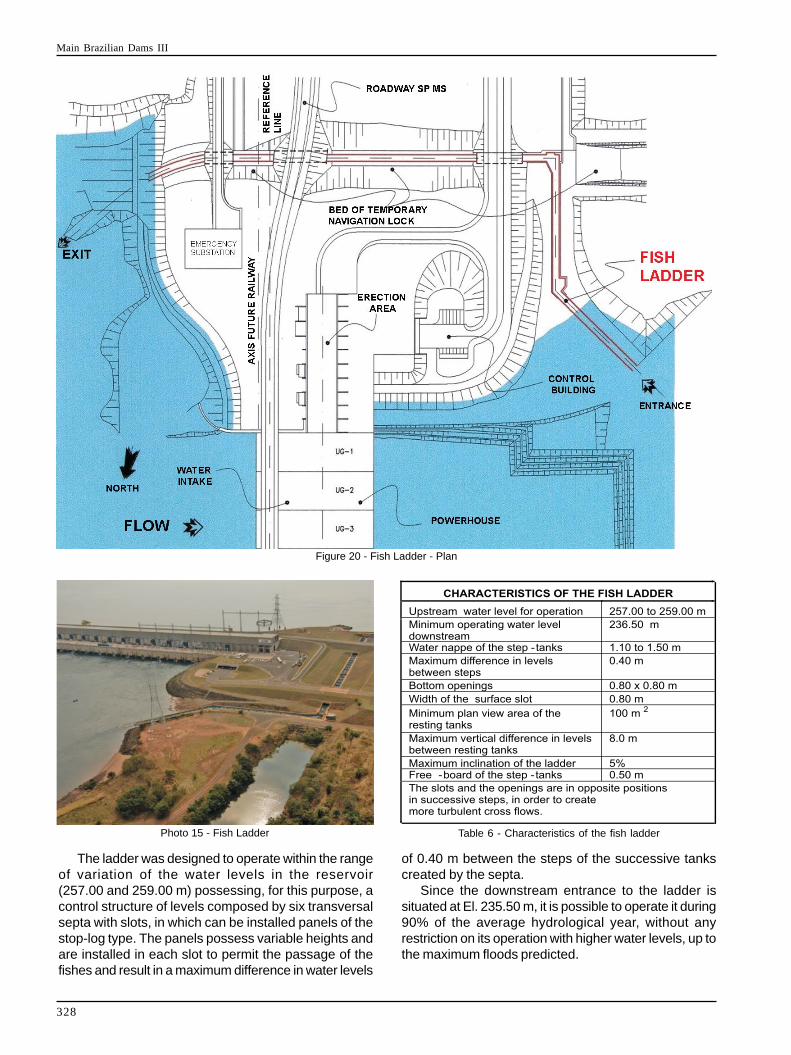
Fish LadderThe fish ladder is located in the left bank, taking into
consideration the criteria for the attraction and restitutionof fishes, the interferences with the earth damdownstream, the roadway system and the substation.Advantage was taken of the excavations resulting fromthe implantation of the provisional navigational lockconstructed at the time of the diversion and subsequentlyde-activated after the conclusion of the permanentnavigation lock.
The ladder is basically composed by the point ofattraction, the channel of ascent, the resting tanks andthe structure of control and outlet. See the general layoutin Figure 20, Photo 15 and the principal characteristicsof Table 6.
Figure 17 - Intake/Powerhouse - Stretch without Light Basalt
Figure 18 - Intake/Powerhouse - Partial Excavation of LightBasalt with a Cut-off
Figure 19 - Permanent Navigation Lock - Typical Cross Sectionand Aerial View
Main Brazilian Dams III
328
The ladder was designed to operate within the rangeof variation of the water levels in the reservoir(257.00 and 259.00 m) possessing, for this purpose, acontrol structure of levels composed by six transversalsepta with slots, in which can be installed panels of thestop-log type. The panels possess variable heights andare installed in each slot to permit the passage of thefishes and result in a maximum difference in water levels
of 0.40 m between the steps of the successive tankscreated by the septa.
Since the downstream entrance to the ladder issituated at El. 235.50 m, it is possible to operate it during90% of the average hydrological year, without anyrestriction on its operation with higher water levels, up tothe maximum floods predicted.
Figure 20 - Fish Ladder - Plan
Table 6 - Characteristics of the fish ladderPhoto 15 - Fish Ladder
Main Brazilian Dams III
329
In the development of the executive project of theladder, various tests and trials were conducted on thehydraulic small scale model of the dam, with a view toascertaining the best position for the attraction point.
It can be observed that the ladder was fitted with anupper protection in wire mesh along its route, with thepurpose of preventing that some fishes, in overcomingthe steps might leap over the sidewalls, as well as toprevent the action of predators.
The ladder entered operation in the spawning migrationof 2001/2002, since the reservoir only attained itsminimum elevation for the operation of the ladder(257.00 m) in April of 2001.
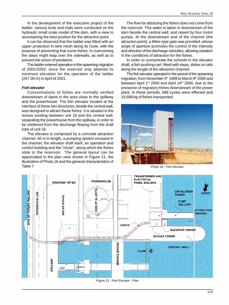
Fish elevatorConcentrations of fishes are normally verified
downstream of dams in the area close to the spillwayand the powerhouse. The fish elevator located at theinterface of these two structures, beside the central wall,was designed to attract these fishes. It is situated in therecess existing between unit 18 and the central wall,separating the powerhouse from the spillway, in order tobe sheltered from the discharge flowing from the drafttube of unit 18.
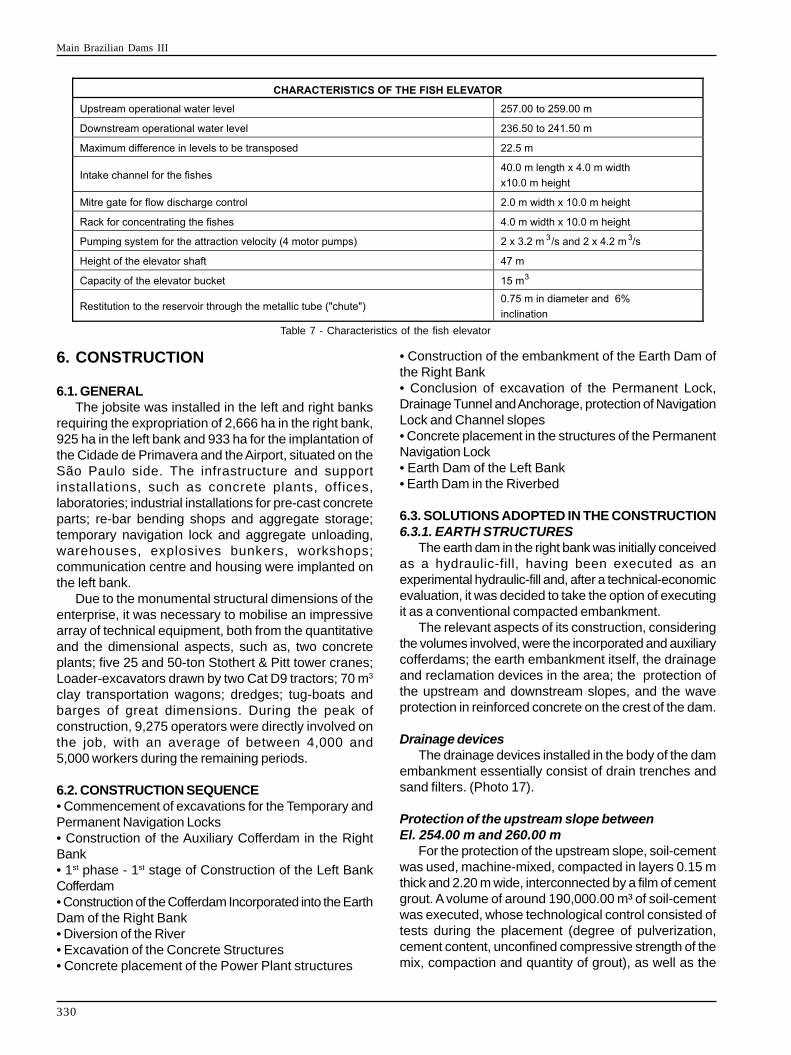
The elevator is composed by a concrete attractionchannel, 40 m in length, a pumping system encased inthe channel, the elevator shaft itself, an operation andcontrol building and the "chute", along which the fishesslide to the reservoir. The general layout can beappreciated in the plan view shown in Figure 21, theillustration of Photo 16 and the general characteristics ofTable 7. Photo 16 - Fish Elevator
Figure 21 - Fish Elevator - Plan
The flow for attracting the fishes does not come fromthe reservoir. This water is taken in downstream of thedam beside the central wall, and raised by four motorpumps. At the downstream end of the channel (theattraction point), a Mitre-type gate was provided, whoseangle of aperture promotes the control of the intensityand direction of the discharge velocities, allowing variationin the conditions of attraction for the fishes.
In order to concentrate the schools in the elevatorshaft, a fish-pushing cart, fitted with steps, slides on railsalong the length of the attraction channel.
The fish elevator operated in the period of the spawningmigration, from November 5th 1999 to March 9th 2000 andbetween April 1st 2000 and April 14th 2000, due to thepresence of migratory fishes downstream of the powerplant. In these periods, 688 cycles were effected and19,688 kg of fishes transported.
Main Brazilian Dams III
330
6. CONSTRUCTION
6.1. GENERALThe jobsite was installed in the left and right banks
requiring the expropriation of 2,666 ha in the right bank,925 ha in the left bank and 933 ha for the implantation ofthe Cidade de Primavera and the Airport, situated on theSão Paulo side. The infrastructure and supportinstallations, such as concrete plants, offices,laboratories; industrial installations for pre-cast concreteparts; re-bar bending shops and aggregate storage;temporary navigation lock and aggregate unloading,warehouses, explosives bunkers, workshops;communication centre and housing were implanted onthe left bank.
Due to the monumental structural dimensions of theenterprise, it was necessary to mobilise an impressivearray of technical equipment, both from the quantitativeand the dimensional aspects, such as, two concreteplants; five 25 and 50-ton Stothert & Pitt tower cranes;Loader-excavators drawn by two Cat D9 tractors; 70 m3
clay transportation wagons; dredges; tug-boats andbarges of great dimensions. During the peak ofconstruction, 9,275 operators were directly involved onthe job, with an average of between 4,000 and5,000 workers during the remaining periods.
6.2. CONSTRUCTION SEQUENCE• Commencement of excavations for the Temporary andPermanent Navigation Locks• Construction of the Auxiliary Cofferdam in the RightBank• 1st phase - 1st stage of Construction of the Left BankCofferdam• Construction of the Cofferdam Incorporated into the EarthDam of the Right Bank• Diversion of the River• Excavation of the Concrete Structures• Concrete placement of the Power Plant structures
• Construction of the embankment of the Earth Dam ofthe Right Bank• Conclusion of excavation of the Permanent Lock,Drainage Tunnel and Anchorage, protection of NavigationLock and Channel slopes• Concrete placement in the structures of the PermanentNavigation Lock• Earth Dam of the Left Bank• Earth Dam in the Riverbed
6.3. SOLUTIONS ADOPTED IN THE CONSTRUCTION6.3.1. EARTH STRUCTURES
The earth dam in the right bank was initially conceivedas a hydraulic-fill, having been executed as anexperimental hydraulic-fill and, after a technical-economicevaluation, it was decided to take the option of executingit as a conventional compacted embankment.
The relevant aspects of its construction, consideringthe volumes involved, were the incorporated and auxiliarycofferdams; the earth embankment itself, the drainageand reclamation devices in the area; the protection ofthe upstream and downstream slopes, and the waveprotection in reinforced concrete on the crest of the dam.
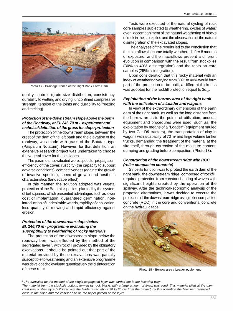
Drainage devicesThe drainage devices installed in the body of the dam
embankment essentially consist of drain trenches andsand filters. (Photo 17).
Protection of the upstream slope betweenEl. 254.00 m and 260.00 m
For the protection of the upstream slope, soil-cementwas used, machine-mixed, compacted in layers 0.15 mthick and 2.20 m wide, interconnected by a film of cementgrout. A volume of around 190,000.00 m³ of soil-cementwas executed, whose technological control consisted oftests during the placement (degree of pulverization,cement content, unconfined compressive strength of themix, compaction and quantity of grout), as well as the
Table 7 - Characteristics of the fish elevator
Main Brazilian Dams III
331
quality controls (grain size distribution, consistency,durability to wetting and drying, unconfined compressivestrength, tension of the joints and durability to freezingand melting).
Protection of the downstream slope above the bermof the Roadway, at El. 246.70 m - experiment andtechnical definition of the grass for slope protection
The protection of the downstream slope, between thecrest of the dam of the left bank and the elevation of theroadway, was made with grass of the Batatais type(Paspalum Notatum). However, for that definition, anextensive research project was undertaken to choosethe vegetal cover for these slopes.
The parameters evaluated were: speed of propagation,efficiency of the cover, rusticity (the capacity to supportadverse conditions), competitiveness (against the growthof invasive species), speed of growth and aestheticcharacteristics (landscape effect).
In this manner, the solution adopted was vegetalprotection of the Batatais species, planted by the systemof turf squares, which presented advantages such as lowercost of implantation, guaranteed germination, non-introduction of undesirable weeds, rapidity of application,less quantity of mowing and rapid efficiency againsterosion.
Protection of the downstream slope belowEl. 246,70 m - programme evaluating thesusceptibility to weathering of rocky materials
The protection of the downstream slope below theroadway berm was effected by the method of thesegregated layer 2, with rockfill provided by the obligatoryexcavations. It should be pointed out that part of thematerial provided by these excavations was partiallysusceptible to weathering and an extensive programmewas developed to evaluate quantitatively the disintegrationof these rocks.
Tests were executed of the natural cycling of rockcore samples subjected to weathering, cycles of water/oven, accompaniment of the natural weathering of blocksof rock in the stockpiles and the observation of the naturaldisintegration of the excavated slopes.
The analyses of the results led to the conclusion thatthe microflows become totally weathered after 8 monthsof exposure, and the macroflows present a differentevolution in comparison with the result from stockpiles(30% to 40% disintegration) and the tests on coresamples (25% disintegration).
Upon consideration that this rocky material with anindex of weathering varying from 30% to 40% would formpart of the protection to be built, a different thicknesswas adopted for the rockfill protection equal to 3d
50.
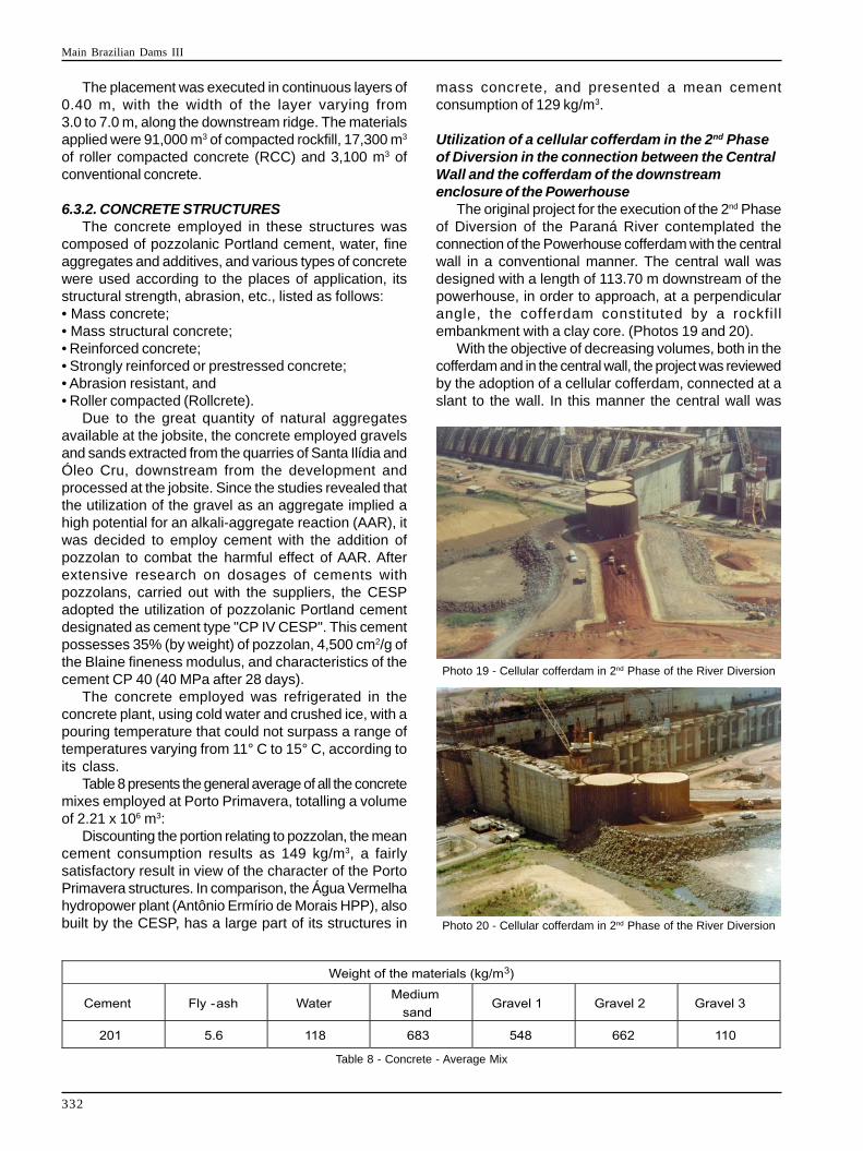
Exploitation of the borrow area of the right bankwith the utilization of a Loader and wagons
In view of the extraordinary dimensions of the earthdam of the right bank, as well as the long distance fromthe borrow areas to the points of utilization, unusualequipment and procedures were used, such as, theexploitation by means of a "Loader" (equipment hauledby two Cat D9 tractors), the transportation of clay inwagons with a capacity of 70 m³ and large volume tankertrucks, demanding the treatment of the material at thesite itself, through correction of the moisture content,dumping and grading before compaction. (Photo 18).
Construction of the downstream ridge with RCC(roller compacted concrete)
Since its function was to protect the earth dam of theright bank, the downstream ridge, composed of rockfill,required protection from constant beating of waves withsignificant heights created by the operation of thespillway. After the technical-economic analysis of theproposed alternatives, it was decided to execute theprotection of the downstream ridge using roller compactedconcrete (RCC) in the core and conventional concreteon the hydraulic face.
Photo 17 - Drainage trench of the Right Bank Earth Dam
Photo 18 - Borrow area / Loader equipment
2 The transition by the method of the single segregated layer was carried out in the following way:The material from the stockpile bottom, formed by rock blocks with a large amount of fines, was used. This material piled at the damcrest was pushed by a bulldozer with the blade raised about 20 to 30 cm from the ground, by this operation the finer part remainedclose to the slope and the coarser one on the upper portion of the layer.
Main Brazilian Dams III
332
The placement was executed in continuous layers of0.40 m, with the width of the layer varying from3.0 to 7.0 m, along the downstream ridge. The materialsapplied were 91,000 m3 of compacted rockfill, 17,300 m3
of roller compacted concrete (RCC) and 3,100 m3 ofconventional concrete.
6.3.2. CONCRETE STRUCTURESThe concrete employed in these structures was
composed of pozzolanic Portland cement, water, fineaggregates and additives, and various types of concretewere used according to the places of application, itsstructural strength, abrasion, etc., listed as follows:• Mass concrete;• Mass structural concrete;• Reinforced concrete;• Strongly reinforced or prestressed concrete;• Abrasion resistant, and• Roller compacted (Rollcrete).
Due to the great quantity of natural aggregatesavailable at the jobsite, the concrete employed gravelsand sands extracted from the quarries of Santa Ilídia andÓleo Cru, downstream from the development andprocessed at the jobsite. Since the studies revealed thatthe utilization of the gravel as an aggregate implied ahigh potential for an alkali-aggregate reaction (AAR), itwas decided to employ cement with the addition ofpozzolan to combat the harmful effect of AAR. Afterextensive research on dosages of cements withpozzolans, carried out with the suppliers, the CESPadopted the utilization of pozzolanic Portland cementdesignated as cement type "CP IV CESP". This cementpossesses 35% (by weight) of pozzolan, 4,500 cm2/g ofthe Blaine fineness modulus, and characteristics of thecement CP 40 (40 MPa after 28 days).
The concrete employed was refrigerated in theconcrete plant, using cold water and crushed ice, with apouring temperature that could not surpass a range oftemperatures varying from 11° C to 15° C, according toits class.
Table 8 presents the general average of all the concretemixes employed at Porto Primavera, totalling a volumeof 2.21 x 10⁶ m3:
Discounting the portion relating to pozzolan, the meancement consumption results as 149 kg/m3, a fairlysatisfactory result in view of the character of the PortoPrimavera structures. In comparison, the Água Vermelhahydropower plant (Antônio Ermírio de Morais HPP), alsobuilt by the CESP, has a large part of its structures in
mass concrete, and presented a mean cementconsumption of 129 kg/m3.
Utilization of a cellular cofferdam in the 2nd Phaseof Diversion in the connection between the CentralWall and the cofferdam of the downstreamenclosure of the Powerhouse
The original project for the execution of the 2nd Phaseof Diversion of the Paraná River contemplated theconnection of the Powerhouse cofferdam with the centralwall in a conventional manner. The central wall wasdesigned with a length of 113.70 m downstream of thepowerhouse, in order to approach, at a perpendicularangle, the cofferdam constituted by a rockfillembankment with a clay core. (Photos 19 and 20).
With the objective of decreasing volumes, both in thecofferdam and in the central wall, the project was reviewedby the adoption of a cellular cofferdam, connected at aslant to the wall. In this manner the central wall was
Table 8 - Concrete - Average Mix
Photo 19 - Cellular cofferdam in 2nd Phase of the River Diversion
Photo 20 - Cellular cofferdam in 2nd Phase of the River Diversion
Main Brazilian Dams III
333
shortened to a total length of 74.20 m downstream fromthe powerhouse (39.50 m less than the original design).
Part of this cofferdam corresponds to a cellularcofferdam 24.0 m in height, provided with 2 principal cellswith a diameter of 24.0 m and two connecting secondaries.
At the time, taking into account the costs and thetime limits, it was decided to reuse the sheet pilesemployed in the cellular cofferdams of the TucuruíHydroelectric Power Plant.
This cofferdam fulfilled its objectives of dewatering thearea downstream of the powerhouse, however, with theinstallation of a lane for the crossing to the right bank,and which was subjected to the traffic of off-road trucks,the sheet piles commenced to shift. This was verified inthe course of monitoring the instrumentation installed.After five years the connecting cell and one of the principalcells broke towards the side of the powerhouse
Immediately after the occurrence, the area wasisolated and measures were taken to repair the stabilityof the affected cells. There was a lowering of the elevationof the cofferdam by 2.80 m and the movement of traffic tothe right bank was effected by barge. There were nocasualties.
Execution of the drainage tunnel and anchorage ofthe lock
With the objective of lowering the water table andreducing the hydrostatic pressures, as well as anchoringthe right side wall of the navigation lock, a tunnel wasexecuted in the sandstone bedrock at El. 246.00, alongthe entire extension of the chamber, whose executivesequence of excavation was developed on two fronts.The apertures, protected by a row of anchor bolts in theperimeter at the level of the excavation, have their portalsprotected by wire mesh and shotcrete.
The average overall production was about 1.00 m/dayin the downstream face and 1.16 m/day in the upstreamface; figures that were considered normal and satisfactoryin jobs of these dimensions and rock of this nature. Meanvalues of around 3.35 m/day were attained under idealconditions.
Special precautions were taken during the excavationby blasting, principally as a result of the following factors:• The existence of an external slope already excavated to itsfinal geometry, between the El. 252.50 m and 263.00 m.• The occurrence in the rock mass of significant amountsof tie-rods, of 22.00 m, already installed previously, fortemporary stabilization of the above-mentioned slope.• The possibility of the occurrence, along the route forthe tunnel, of pockets of material with worsegeomechanical characteristics that might totally orpartially destabilize the work front.• The existence of subvertical discontinuities of greatextension that might destabilize or provoke largedeformations in the rock mass.
For these reasons, the excavation works were
monitored by measuring the vibrations induced by theblasting. The analyses of these vibrations showed a highdispersion of the results, which, without doubt, can beattributed to the phenomenon of the superposition of theeffects of one blasting delay upon another, demonstratinga more transmissive medium than the one considered inthe design.
This confirmation demonstrated the need forredoubling the precautions in future excavations, not somuch in the sense of reducing the values of the loadingrates or the maximum charges per delay, but moreoverto use sufficiently spaced delays to avoid thesuperimposition of unexpected effects.
Sealing the Foundation of the 1st Phase - 2nd StageCofferdam of the Left Bank
The cofferdam of the 1st Phase - 2nd Stage of the leftbank was seated upon a fairly permeable alluvial layer,with thickness varying form 6.0 to 12.0 m, essentiallycharacterised by sandy horizons intercalated withconglomeratic slabs (sandy gravel cemented byferruginous compounds) of a thickness varying from20 cm to 80 cm in up to 5 distinct levels, and withintercalations of soft clay levels.
The alternatives analysed for sealing the alluvial layerwere: concrete piles by the CCP process (ChemicalChurning Pile) or the execution of a plastic diaphragmwall. The CCP technique consists, fundamentally, inthe execution of soil improvement with cement "in situ",through the introduction of cement grout into the terrainat great speed by special devices. This injection isexecuted by pumping the grout at extremely highpressures, forcing it to traverse very small openings. Thejet obtained in this manner destroys the structure of thesoil, promoting the mixing and homogenization of thismaterial with the grout injected. The solution chosen wasthat of the CCP piles, since the alternative of the plasticdiaphragm faced its principal disadvantage in the difficultyof piercing the slabs of conglomerate and guaranteeingthe stability of the walls of the panels.
A similar process to that of the CCP, called theROTOCRETE, was executed on the upstream stretch ofthe cofferdam. This method consists in executing columnsthrough a drill that goes simultaneously perforating andmechanically executing in situ a mixture of cement groutand soil.
The analysis of the instrumentation, installed to verifythe behaviour of this sealing curtain, showed that itsperformance was lower than expected, not fulfilling theobjective of decreasing the gradients of seepage.Nevertheless, some sealing effect did occur, homogenizingand reducing the permeability of the materials of that layer,since the dewatering of the enclosure permitted observinga reduction in the seepage rate.
After the diversion, the location was excavated and inthe samples from the columns that had been executedgreat openings could be observed, resulting from the lack
Main Brazilian Dams III
334
of verticality between them, columns that didn't preservetheir initial diameter, lack of penetration into the rock mass,etc., which can be explained by the great differencebetween the strengths of the materials existing in the area(soft sands, conglomeratic slabs and lenses of soft clay).
7. ENVIRONMENTAL, SOCIAL ANDECONOMIC ASPECTS
In order to mitigate the impacts resulting from theimplantation of the development, and also taking intoconsideration that the impacts traditionally surpass thelegal obligations of mitigation and compensation, theCESP implanted various environmental programmes ofa mitigating and compensatory nature in accordance withEIA-RIMA (Environmental Impact Studies), developed inthe period of 1992 to 1994 by the consortium constitutedby THEMAG-ENGEA-UMAH.
These programmes, subdivided into social-economicand physical-biotic, were complemented by specificactivities of environmental management, whoseintroduction was granted priority in the last two years.
7.1. SOCIAL-ECONOMICS PROGRAMMESThese Programmes followed the results of the
EIA/RIMA, with the intention of minimizing the impactscaused by the implantation of power plants on thepopulations, the economic activities, the existinginfrastructure and the historical, cultural andarchaeological heritage of the region of influence.• Programmes for Resettling the Affected Population:involve rural and urban resettlements• Programmes for Maintaining the Economic Activities:involve the continuity of the activities relating to: brickkilns - ceramics, quarrying sand and gravel, fishery.• Programmes of Recomposition and Improvement of theHighway Infrastructure, Sanitation and Transport:implantation of roads, crossings, port structure, sanitationinfrastructure (public water supply and distribution,sewage collection and treatment), electric power andtelephone infrastructure (removal and reallocation ofelectricity networks), reallocation of community centres,schools and public health centres, where, in some casesof schools and health centres the compensation wasused to equip and enlarge the existing buildings.Recreation activities were also implemented by thecreation of specific areas and parks.• Programme of Archaeological Rescue and Valorisationof the Regional Memory: the rescue activitiescommenced in 1993, with records of an assembly of253 archaeological occurrence sites and the collectionof a heritage surpassing 50,000 artefacts.
7.2. PHYSICAL-BIOTIC PROGRAMMES7.2.1. BIOTIC
This programme covers four principal activities:
management of the flora, the fauna, fishery administrationand implementation of units for conservation and protectedareas.• Programme for Managing the Flora: its objective is therescue and preservation of the regional flora, providingrecuperation and maintenance of the environmentalquality in the areas of influence of reservoirs. At present,the CESP is in the process of certifying these projectsunder the clean development mechanism (CDM)promoted in the Kyoto Protocol of Emission Control.• Programme of Management and Conservation of theFauna: its objective is to document the fauna, subsidizeits management, develop reproduction projects andanalyse translocations of species. For example: themarsh deer, puma, jaguar, howler monkey and blackmonkey.• Programme of Fishery Management: is equipped withsystems for the transposition of fishes (elevator and fishladder) which address the monitoring of the ichthyofaunaand its population dynamics.
7.2.2. PHYSICAL ENVIRONMENTThis programme comprises five principal activities, i.e.:
• Programme of control of erosion - silt deposition: itsscope is the control over erosive processes andconsequently, the silt deposition in the basins thatcontribute to the reservoir.• Programme for protecting the slopes of the banks: itsobjective is to promote actions directed to theconservation and recuperation of unstable marginalslopes or those subject to instability within the reservoirby means of the systematic monitoring of the margins.• Programme for mitigating the impacts of the elevationof the water table: its purpose is to identify the impactsresulting from the elevation of the water table caused bythe filling of the reservoir, including the water quality, bymonitoring the water levels and the water quality.• Programme for recuperating degraded areas: its purposeis to restore to the dominating landscape of thesurrounding region the areas that were degraded by theexecution of the structures of the power plant andcomplementary works.• Programme of scientific research on the physicalenvironment: its purpose is to characterise the alluvialdeposits, their origin, constitution, lithogenetic processes,paleoclimatic influences, contemplating the areas ofgeology, geomorphology and lithology.
As a complement to the set of physical-bioticprogrammes, the CESP is implanting three state parksand one Private Reserve of the Natural Patrimony (PRNP),as follows:• Parque Estadual das Várzeas do RioIvinhema 73,345.15 ha• Parque Estadual do Rio Aguapeí 9,043.97 ha• Parque Estadual do Rio do Peixe 7,720.00 ha• PRNP Cisalpina 6,261.75 ha
Main Brazilian Dams III
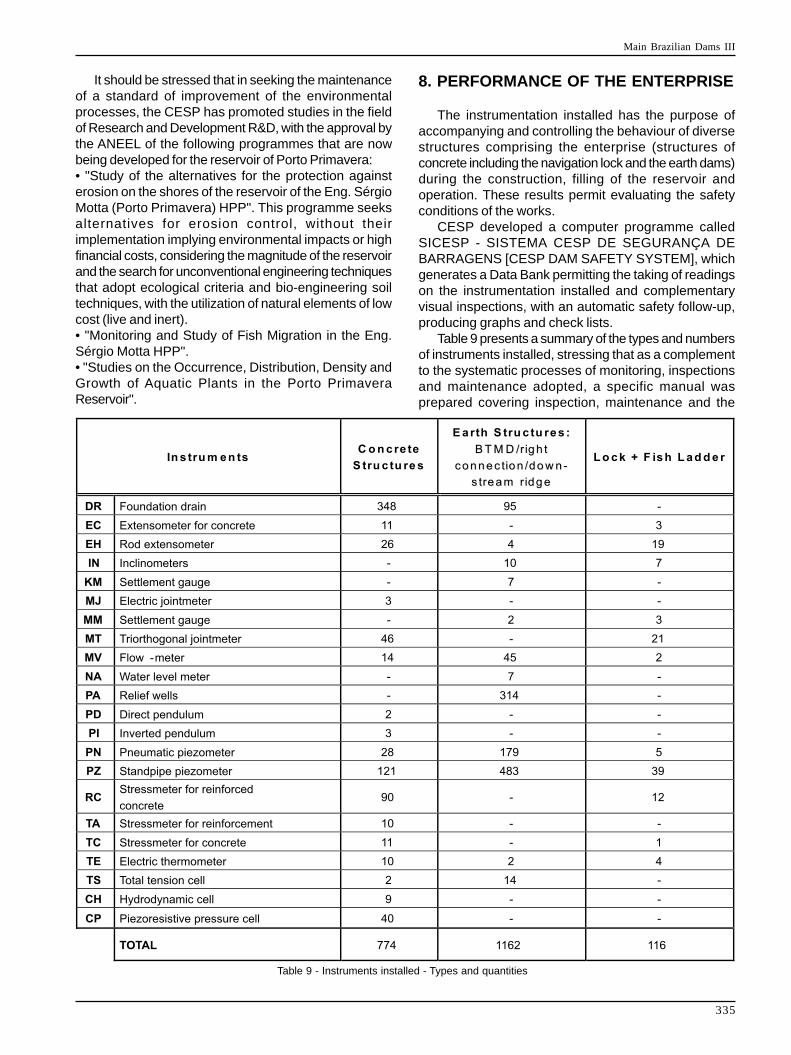
335
It should be stressed that in seeking the maintenanceof a standard of improvement of the environmentalprocesses, the CESP has promoted studies in the fieldof Research and Development R&D, with the approval bythe ANEEL of the following programmes that are nowbeing developed for the reservoir of Porto Primavera:• "Study of the alternatives for the protection againsterosion on the shores of the reservoir of the Eng. SérgioMotta (Porto Primavera) HPP". This programme seeksalternatives for erosion control, without theirimplementation implying environmental impacts or highfinancial costs, considering the magnitude of the reservoirand the search for unconventional engineering techniquesthat adopt ecological criteria and bio-engineering soiltechniques, with the utilization of natural elements of lowcost (live and inert).• "Monitoring and Study of Fish Migration in the Eng.Sérgio Motta HPP".• "Studies on the Occurrence, Distribution, Density andGrowth of Aquatic Plants in the Porto PrimaveraReservoir".
8. PERFORMANCE OF THE ENTERPRISE
The instrumentation installed has the purpose ofaccompanying and controlling the behaviour of diversestructures comprising the enterprise (structures ofconcrete including the navigation lock and the earth dams)during the construction, filling of the reservoir andoperation. These results permit evaluating the safetyconditions of the works.
CESP developed a computer programme calledSICESP - SISTEMA CESP DE SEGURANÇA DEBARRAGENS [CESP DAM SAFETY SYSTEM], whichgenerates a Data Bank permitting the taking of readingson the instrumentation installed and complementaryvisual inspections, with an automatic safety follow-up,producing graphs and check lists.
Table 9 presents a summary of the types and numbersof instruments installed, stressing that as a complementto the systematic processes of monitoring, inspectionsand maintenance adopted, a specific manual wasprepared covering inspection, maintenance and the
Table 9 - Instruments installed - Types and quantities
Main Brazilian Dams III
336
precautions to be observed in the earth dam of the rightbank and its foundations throughout the period ofoperation of the plant, with its principal focus on thequestions relating to the drainage system installed.
Taking into account the extent of the enterprise, with960 m relating to concrete structures and 10,400 m tothe earth dams of the right bank, in the riverbed and theleft bank, the considerations concerning dam safety weredivided into: Concrete Structures and Earth Structures.
It can be observed that with the filling of the reservoirin two stages - the first to El. 253.00 m and finally toEl. 257.00 m, in the analyses of the instrumentationinstalled in the first stage, despite the load imposedrepresenting a portion of the total to be effectivelysupported by the structures, it was possible tocharacterise a standard of behaviour and even checksome of the project parameters, implement additionaltreatments and revaluate criteria adopted in order toconduct all the structures within the standards of safetyforecast in the project of El. 257.00 m and 259.00 m.
8.1. EARTH STRUCTURESAs a general concept, the dam safety, whose design
was based on drainage as the principal foundationtreatment, particularly depends on the good functioningof this drainage system.
All the instrumentation existing in the earth dam(standpipe and pneumatic piezometers) served thepurpose of monitoring the behaviour of this system underthe effect of the uplift pressures. Corrective measures,such as, relief wells, drainage holes and blankets werecarried out in order to lower these uplift pressures. It cannow be concluded that the values observed are withinthe levels established by the design criteria and presentadequate conditions of safety.
As a complement to the safety measures andmonitoring, the planning included inspections and theeventual unblocking of the drainage tubing capable ofbeing accessed using filming equipment fitted to smalldiameter probes, called CCTV (closed circuit television).This measure was tested and proved efficient.
A noteworthy programme is that of the "goldenmussel" in the stretch of the earth dam, whose detectionwas reported in the concrete structures and in somemechanical equipment of the power plant.
The measures taken by the CESP for the downstreamportion went beyond the visual inspections, on the surfaceand underwater, involving the implantation of rosettes andacrylic plaques to control the occurrence while yet in itslarval stage in stretches of the dam where the internaldrainage outlets occurred under submerged conditionsin direct contact with the water of the Paraná or Baíarivers. (Stretches of the dam on the plain of the BaíaRiver and in the riverbed).
The inspections carried out up to the present havefailed to record the presence of this mollusc in the earthstructures and their downstream drainage systems.
The risk of this occurrence however, still exists and raisesfears concerning the performance and the safety of thedam.
While there is still no certainty regarding the questionsraised above, strict monitoring has also to be continuedin the regions of the alluvial terrace, paleo-island andParaná plateau, which, although presenting only a smallrisk of contamination without the occurrence of floods,are very fragile in the case of an infestation. In thesestretches, the drainage outlets occur through discretepoints that collect the water from the perforated tubing.An infestation of these tubes represents a serious riskto the safety of the dam.
8.2. CONCRETE STRUCTURESIt can be stated, in a general manner, that the
auscultation system is functioning perfectly, being fullysatisfactory to record any alterations of the stressesimposed on the structures and that the values observedare within the limits established in the design criteria,presenting adequate safety conditions.
With the piezometric data in hand, the real upliftpressure diagrams were compared with the projecthypotheses, permitting the assessment of the realconditions of seepage through the foundations, as wellas the stability conditions of the structures, thus provingtheir conformity with the design criteria.
The readings from the strain meters compared theobserved displacements with those predicted in theproject, thus checking the deformability of the structuresand their foundations, which were in line with the designprojections.
The instrumentation also checked the efficiency ofthe treatment system applied to the bedrock (Grout anddrainage curtain), with the effective control of the upliftpressures acting in the foundations, with readings withinthe predictions of the project.
The seepage flowing into the foundation drains, afterthe 2nd phase of the diversion (1993) was considerablygreater than estimated by the project, particularly in theregion of the microflows and in the vertical wall to theerection area. Measures were adopted, such as blockingsome drains with control of uplift pressures and whichproved effective and, together with the phenomenon ofthe silting of the reservoir, have resulted in a gradualdecrease, as shown in Table 10.
Analysis of the results of the takes by the groutcurtains eliminated the need for additional perforations,either complementary or quaternary, forecast by thetechnical specification. This situation can be explainedby the characteristics of the rock masses injected, wherethe groutable domains characterised by the horizontaldiscontinuities of high persistency (lateral extension) andhigh hydraulic conductivity present in the macroflows wereamply grouted, against the non-groutable domain in themicroflows, characterised by localized portions of highlyfractured rocky mass, low persistence and high hydraulic
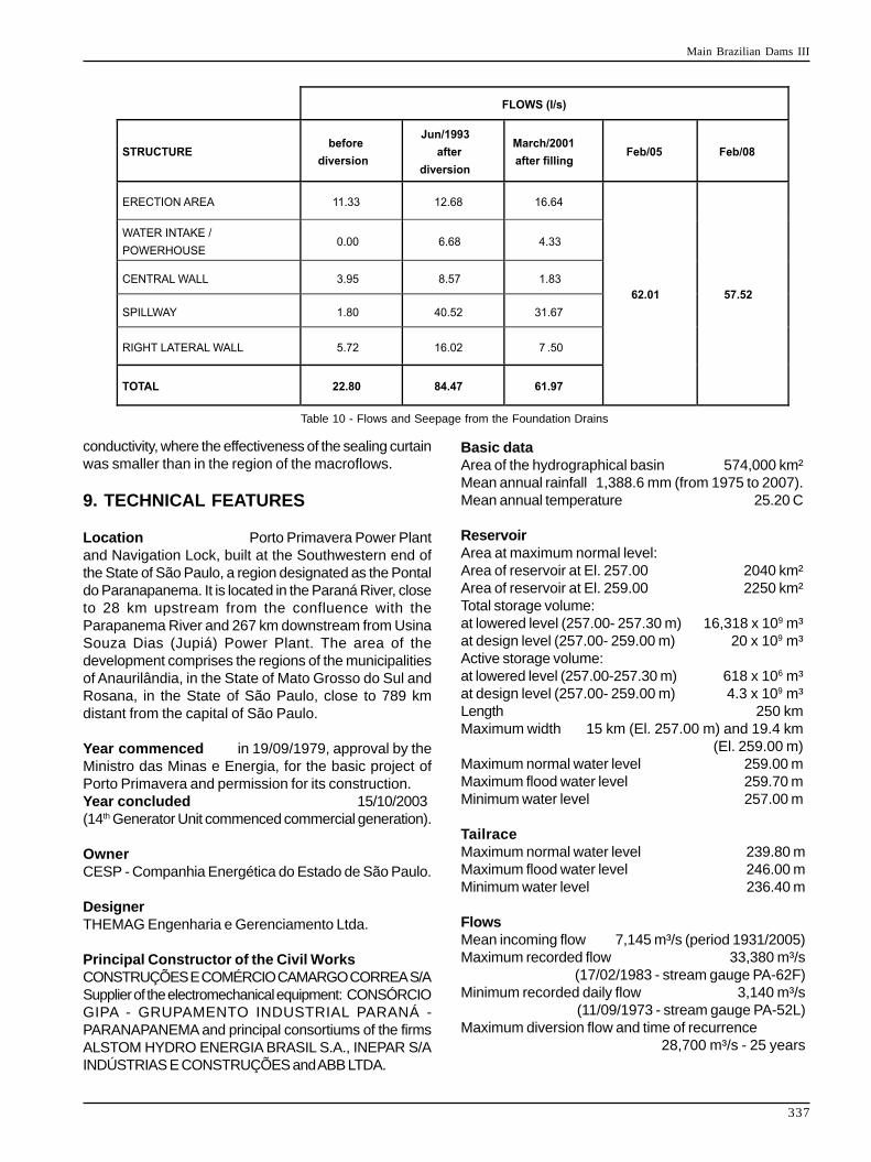
Main Brazilian Dams III
337
conductivity, where the effectiveness of the sealing curtainwas smaller than in the region of the macroflows.
9. TECHNICAL FEATURES
Location Porto Primavera Power Plantand Navigation Lock, built at the Southwestern end ofthe State of São Paulo, a region designated as the Pontaldo Paranapanema. It is located in the Paraná River, closeto 28 km upstream from the confluence with theParapanema River and 267 km downstream from UsinaSouza Dias (Jupiá) Power Plant. The area of thedevelopment comprises the regions of the municipalitiesof Anaurilândia, in the State of Mato Grosso do Sul andRosana, in the State of São Paulo, close to 789 kmdistant from the capital of São Paulo.
Year commenced in 19/09/1979, approval by theMinistro das Minas e Energia, for the basic project ofPorto Primavera and permission for its construction.Year concluded 15/10/2003(14th Generator Unit commenced commercial generation).
OwnerCESP - Companhia Energética do Estado de São Paulo.
DesignerTHEMAG Engenharia e Gerenciamento Ltda.
Principal Constructor of the Civil WorksCONSTRUÇÕES E COMÉRCIO CAMARGO CORREA S/ASupplier of the electromechanical equipment: CONSÓRCIOGIPA - GRUPAMENTO INDUSTRIAL PARANÁ -PARANAPANEMA and principal consortiums of the firmsALSTOM HYDRO ENERGIA BRASIL S.A., INEPAR S/AINDÚSTRIAS E CONSTRUÇÕES and ABB LTDA.
Basic dataArea of the hydrographical basin 574,000 km²Mean annual rainfall 1,388.6 mm (from 1975 to 2007).Mean annual temperature 25.20 C
ReservoirArea at maximum normal level:Area of reservoir at El. 257.00 2040 km²Area of reservoir at El. 259.00 2250 km²Total storage volume:at lowered level (257.00- 257.30 m) 16,318 x 109 m³at design level (257.00- 259.00 m) 20 x 109 m³Active storage volume:at lowered level (257.00-257.30 m) 618 x 106 m³at design level (257.00- 259.00 m) 4.3 x 10⁹ m³Length 250 kmMaximum width 15 km (El. 257.00 m) and 19.4 km
(El. 259.00 m)Maximum normal water level 259.00 mMaximum flood water level 259.70 mMinimum water level 257.00 m
TailraceMaximum normal water level 239.80 mMaximum flood water level 246.00 mMinimum water level 236.40 m
FlowsMean incoming flow 7,145 m³/s (period 1931/2005)Maximum recorded flow 33,380 m³/s
(17/02/1983 - stream gauge PA-62F)Minimum recorded daily flow 3,140 m³/s
(11/09/1973 - stream gauge PA-52L)Maximum diversion flow and time of recurrence
28,700 m³/s - 25 years
Table 10 - Flows and Seepage from the Foundation Drains
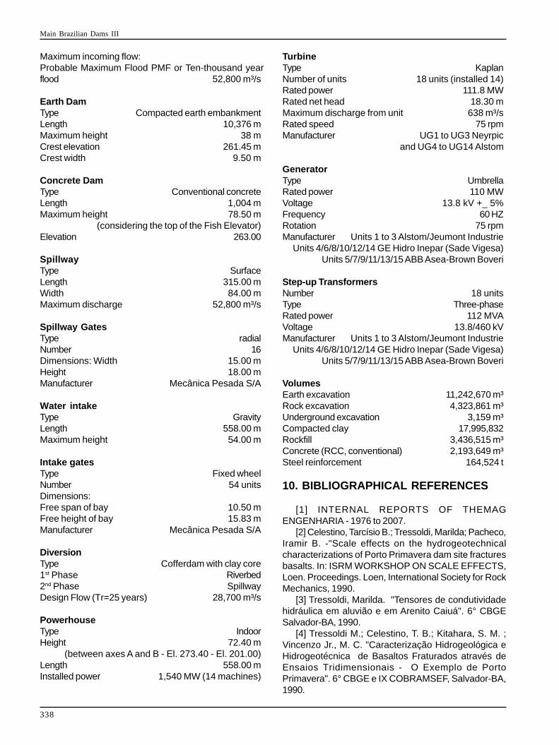
Main Brazilian Dams III
338
Maximum incoming flow:Probable Maximum Flood PMF or Ten-thousand yearflood 52,800 m³/s
Earth DamType Compacted earth embankmentLength 10,376 mMaximum height 38 mCrest elevation 261.45 mCrest width 9.50 m
Concrete DamType Conventional concreteLength 1,004 mMaximum height 78.50 m
(considering the top of the Fish Elevator)Elevation 263.00
SpillwayType SurfaceLength 315.00 mWidth 84.00 mMaximum discharge 52,800 m³/s
Spillway GatesType radialNumber 16Dimensions: Width 15.00 mHeight 18.00 mManufacturer Mecânica Pesada S/A
Water intakeType GravityLength 558.00 mMaximum height 54.00 m
Intake gatesType Fixed wheelNumber 54 unitsDimensions:Free span of bay 10.50 mFree height of bay 15.83 mManufacturer Mecânica Pesada S/A
DiversionType Cofferdam with clay core1st Phase Riverbed2nd Phase SpillwayDesign Flow (Tr=25 years) 28,700 m³/s
PowerhouseType IndoorHeight 72.40 m
(between axes A and B - El. 273.40 - El. 201.00)Length 558.00 mInstalled power 1,540 MW (14 machines)
TurbineType KaplanNumber of units 18 units (installed 14)Rated power 111.8 MWRated net head 18.30 mMaximum discharge from unit 638 m³/sRated speed 75 rpmManufacturer UG1 to UG3 Neyrpic
and UG4 to UG14 Alstom
GeneratorType UmbrellaRated power 110 MWVoltage 13.8 kV +_ 5%Frequency 60 HZRotation 75 rpmManufacturer Units 1 to 3 Alstom/Jeumont Industrie
Units 4/6/8/10/12/14 GE Hidro Inepar (Sade Vigesa)Units 5/7/9/11/13/15 ABB Asea-Brown Boveri
Step-up TransformersNumber 18 unitsType Three-phaseRated power 112 MVAVoltage 13.8/460 kVManufacturer Units 1 to 3 Alstom/Jeumont Industrie
Units 4/6/8/10/12/14 GE Hidro Inepar (Sade Vigesa)Units 5/7/9/11/13/15 ABB Asea-Brown Boveri
VolumesEarth excavation 11,242,670 m³Rock excavation 4,323,861 m³Underground excavation 3,159 m³Compacted clay 17,995,832Rockfill 3,436,515 m³Concrete (RCC, conventional) 2,193,649 m³Steel reinforcement 164,524 t
10. BIBLIOGRAPHICAL REFERENCES
[1] INTERNAL REPORTS OF THEMAGENGENHARIA - 1976 to 2007.
[2] Celestino, Tarcísio B.; Tressoldi, Marilda; Pacheco,Iramir B. -"Scale effects on the hydrogeotechnicalcharacterizations of Porto Primavera dam site fracturesbasalts. In: ISRM WORKSHOP ON SCALE EFFECTS,Loen. Proceedings. Loen, International Society for RockMechanics, 1990.
[3] Tressoldi, Marilda. "Tensores de condutividadehidráulica em aluvião e em Arenito Caiuá". 6° CBGESalvador-BA, 1990.
[4] Tressoldi M.; Celestino, T. B.; Kitahara, S. M. ;Vincenzo Jr., M. C. "Caracterização Hidrogeológica eHidrogeotécnica de Basaltos Fraturados através deEnsaios Tridimensionais - O Exemplo de PortoPrimavera". 6° CBGE e IX COBRAMSEF, Salvador-BA,1990.
Main Brazilian Dams III
339
[5] Tressoldi M.; Kitahara, S. M.; Vincenzo Jr., M. C."Alguns Aspectos Hidrogeológicos do Arenito Caiuá dasFundações da Barragem de Porto Primavera". 6° CBGEe IX COBRAMSEF, Salvador-BA, 1990.
[6] Jensen,Pedro D.; Barth,Rubens T.;Martins,Sidney.; Musarra, Maria Luiza; OliveiraFilho,José.E.; Dias, João H. P. "Sistema para atransposição de peixes na Usina Porto Primavera: estudode caso". XV Simpósio de Recursos Hídricos, Curitiba,2003.
[7] Negro, Arsenio; Santos, Newton B. "Hydraulic fillmethod: A feasible alternative for earth dam construction".VI Congresso Panamericano de Mecânica dos Solos eEngenharia de Fundações, Lima-Peru,1979.
[8] Moretti, M. R. "Parâmetros físicos do aterrohidráulico experimental de campo de Porto Primavera".VIII Congresso Brasileiro de Mecânica dos Solos e
Engenharia de fundações, Porto Alegre, 1986.[9]:Vargas, M; Pacheco, I. B.; Moretti, M. R.
"Drenagem versus impermeabilização na otimização dosprojetos de fundação de barragens de terra". XXIISeminário Nacional de Grandes Barragens, SãoPaulo,1997.
[10]:Moretti, M. R.; Pacheco, I. B.; Vargas, M."Behavior of a Dam on a Pervious Foundation withoutImpermeable Elements". 12th Panamerican Conferencefor Soil Mechanics and Geotechnical Engineering and39th US Rock Mechanics Symposium, Cambridge, USA,2003.
[11]:Guimarães M.C.B.; RE G.; Monteiro L.B. "CriticalAnalysis of the Geomechanical Characterization Resultsof an Unusual Basaltic Lithology in Porto PrimaveraPower Plant". VII International Congress of the IAEG,Lisbon, 1994.