Embed Size (px)
Citation preview

The Stirling WarWolf Trebuchet KitRLT.com Industries Copyright, 2007
If any part of these instructions are unreadable, you can download a PDF version from http://www.RLT.com/instructions/StirlingWarWolf.pdf
Tools you will need: Utility Knife Household Scissors Sandpaper Flat File Round or “rat-tail” file (¼ inch) Wood Glue Small clamps or rubber bands
IMPORTANT! Do not return this kit to the store. If any parts are damaged or defective, do not use! Send email to [email protected] to ask for replacement parts.
Finishing tip:Your machine will work better if you do not paint, stain or varnish it. The kind of wood we use will darken to a nice warm golden-brown color over time, faster if exposed to sunlight. However, if you still intend to stain, paint or varnish your model, it's best to do so after each major assembly is completed.
Separating the parts:Do not simply "pop" the parts off the panels with your fingers! If you do it this way you may hurt your fingers or split the wood. Instead, use a utility knife or sturdy pair of scissors to snip the tabs. A pair of wire cutters does an excellent job! Then trim any nubs or fuzzies with household scissors or a utility knife (an X-acto knife works well). Sand or file the edges smooth if necessary.
Putting square pegs in rounded holes:The tenons (pegs) on this model are squared, but the mortises (the holes) are rounded. You'll need to file or sand the edges of the tenons down a little bit so they'll fit into the mortises. Be sure to dry fit them to see if you've filed enough. Too much filing may leave a gap.
Page 1
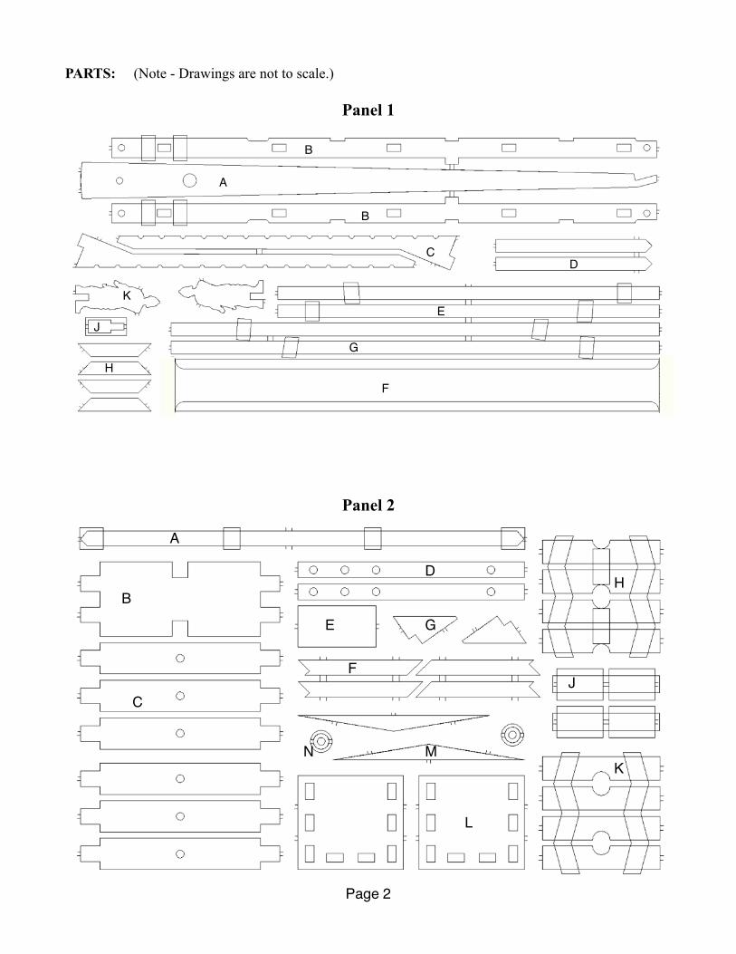
PARTS: (Note - Drawings are not to scale.)
Panel 1
Panel 2
Page 2
A
B
B
CD
E
F
GH
J
K
A
B
C
D
E
F
G
H
J
K
L
MN

Panel 3
Panel 4
Page 3
A
B
C
D
EF
AB
CD
E F
G
H
J

Building the Frame
Cutting dowels: The instructions will reference some dowels of specific lengths at various times. You’ll make these from the long 1/4” and 3/16” diameter dowels. This is easy to do with a pair of scissors. Determine where you will make the cut, then score the dowel at that location with the scissors. Score it all the way around, then just snap it off. If it won't snap easily, just score it a little deeper. Smooth the rough ends with a file or sandpaper, and that's it.
Assembling the sub-frame:
Assemble the parts as in the image on the right. Make sure that all the joints fit together easily and are un-stressed. If they don’t fit together easily, you may need to swap left-for-right so they will. Part 2-A should fit snugly into the corners at the diagonal.
Once you’re satisfied with the fit, glue all the pieces together. Part 2-A doesn’t have much surface contact to glue onto the rest of the frame. Just use enough to hold it in place for now. When we install the side A-frames (later), the A-frame brace will glue into the slot on each end of part 2-A to strengthen it.
Page 4
Part 2-A
Part 1-EPart 1-E
Part 1-GPart 1-G

The side A-Frames:Arrange the pieces according to the photo on the left, but don’t glue them yet. Parts 2-K and 2-H will fit together “clamshell” style to join the top of part 4-J with parts 3-A. When assembled, this is called the Pillow-Block and will hold the main axle (The axle rests on the pillow-block).
Here’s a detail view of the assembled pillow-block and keystone (part 4-B):
Use a straight-edge and verify that the bottom of the A-frame legs are flat and straight. If not, you may need to make some adjustments until they are. Part 4-J is intentionally a tiny bit short to insure that it fits. Just slide it down to meet the baseline, leaving the gap inside the pillow block at the top.
Use the notches in part 1-B to align the bottoms of the A-frame’s legs. You may need to file the corners a bit to get a perfect fit. Glue all the parts of the A-frame together, including part 1-B. IMPORTANT! the hole in part 2-G must be on the same end as the round hole in part 1-B! Be sure to clamp the parts, or use rubber bands to hold the pieces together while the glue sets. Build the other A-frame the same way, and be sure to check that it’s the same as the first A-frame. Lay one on top of the other and make sure the axle holes and base line are the same. If not, the pillow-blocks may be shifted a little bit one way or another, and if they’re not the same on each A-frame, then the axle may tilt or be crooked, and then the counterweight might strike the frame when firing.
Page 5
4-B
2-K
4-J
2-K2-H
2-H
3-A
3-A
2-G2-H
1-B

Attaching the A-Frames to the base:
First you’ll need to attach the a-frames to each other with the five cross-braces (Part 4-D). Cut ten dowel pegs, approximately 7/8” long from the 1/4” diameter dowel rod. Chamfer the ends with a file or sandpaper. Pegs
File or sand the corners of parts 4-D so that they fit easily into the slots in the A-frame base-beams. IMPORTANT! The cross-beams (part 4-D) should be flush with the TOP of the A-frame base beams. The extra space under the cross-beams will be used to route the winch lines.
Notice the keystone piece (4-B) at the top of the A-frame. Decide if you
want this to be facing the outside or inside of the finished machine (most people prefer the keystone to be towards the outside). When all the pegs are inserted into all the holes of the cross-braces, the two A-Frame sides should be fairly stable and no glue is needed.
To attach the A-frame assembly to the sub-frame, put the stubs on the bottom of the A-frame base beams into the notches on the sub-frame cross-beam (2-A). The outrigger braces (part 1-C) fit in the notches at
the corners of the sub-frame and just under the pillow-blocks. Glue and clamp all joints. We use rubber bands to clamp the parts together (photo at left.) (side view, completed)
Page 6

Building the Arm and Counterweight Box
Start with the counterweight box. Cut six dowels 7/8” long from the 1/4” dowel rod and sand or file the edges of all the tenons on parts 2-C and 2-B. Insert the tenons into the mortices on the end caps, part (2-L) so that the sides and bottom of the box are FLUSH with the edges of the end caps (more space inside the box). Once you’re satisfied with the fit, glue them together. (Once again, rubber bands are a great way to hold things together).
Insert parts 2-D into the holes at the bottom of the box so that the
three holes in part 2-D line up with the holes in parts 2-C. Insert the dowels you cut earlier into these holes. Glue part 2-E between the uprights, and parts 2-F bracing the uprights as in the photos at right:
Finally, glue the rockers to the bottom of the box (Parts 2-M).
Each half of the box will hold nine stacks of pennies, forty pennies high. This will provide about four and a half pounds of weight from the pennies. At 1/20th scale, that equates to 18 tons of counterweight!
So, why isn’t it just 4.5 pounds times 20 = 90 pounds? Because weight is another way to measure volume. If something weighs one pound per cubic inch, then 20 pounds of it will be 20 cubic inches. A square 1 inch on each side is 1 square inch. Scaled up 20 times, each side measures 20 inches, and 20 x 20 = 400 square inches in that square. Surface area scales as the square of the linear dimension. A cube that’s 1 inch on a side will be 1 cubic inch, but scaled up 20 times, each side will be 20 inches, and 20 x 20 x 20 = 8000 cubic inches! So, a cube scaled up 20 times will have 8000 times the weight! Weight and volume scale as the cube of the linear dimension. So, a 4.5 lbs, weight scaled up 20 times, is 4.5 x 20 x 20 x 20 = 36000 lbs, or 18 tons!
Page 7
2-L
2-L
2-B2-C
2-D
2-E2-F

The Arm:
Most ancient trebuchet arms seem to have been made from two beams, lashed together. To simulate this, you can draw a line with a pencil (or brown marker) down the center of each side of the arm (part 1-A).
Part 1-J is the release-pin for the sling.
Sand the pin smooth and as round as you can get it. You can glue it to the arm, but it may eventually break, or you might want to replace it with something else in the future. Instead of glue, we’ll use a lashing technique to attach it. Here’s the basic technique for lashing-
Step 1. Step 2. Step 3.
Step 1: Make a loop against your beam. Step 2: Wrap the cord around the beam and over the loop. Be sure to keep the cord as tight as you can during this process. Step 3: Insert the loose end of the cord through the open loop (make it a tight wrap) then pull the loose end under the wrapping using the other loose end (step 3). On some types of cord you can just cut the ends and leave it at that, but on the tip we’re going to need a loop to attach things to. So, bring the loose ends together over the wrapping and tie them together. You may want to practice this a couple of times before you make it permanent. Add some more wrappings (three or four) down the length of the arm for effect. When you’re done it should look something like this:
We added a loop around the pin so it can’t slip out. You’ll also need a loop near the axle (on the long side of the arm) to attach the trolly line. Here’s the arm with the trolley line and counterweight box:
Page 8

Attaching the Arm to the Counterweight Box and Frame: There are six spacers in the kit, but two of them are smaller than the rest. We need the small ones, Parts 2-N. We’ll also need a 1/4” diameter dowel 2-3/4 inches long.
Put a spacer between the arm and the counterweight hangers, and hold it all together with the dowel, as in the photo at right:
When you install the arm on the frame, the counterweight goes towards short end, and the sling goes towards the extended end of the frame. The pin should angle upwards when the arm is level.
OPTIONAL: glue the axle support gussets (Part 2-G) and axle cradles (Part 2-J) to the frame as in the photo at left. Insert the 1/2” diameter axle dowel to insure that they are straight and level. Don’t get any glue on the axle itself. If you ever need to remove the arm, you’ll have to remove the axle to do it.
Also Optional: We’ve included an extra set of axle cradles so you can put them on top of the axle, clam-shell style, if you don’t
like the look of an exposed axle (glue to the other cradle, not the axle!)
Another option: Glue the axle cradle clamshells together and use them as spacers to keep the arm centered. In medieval times, the axle would have been a square beam that was rounded only where it needed to be round- at the arm and/or at the pillow-blocks. Using the cradles as spacers would simulate this effect.
You must use one of these options to keep the arm centered, or the counterweight box will strike the frame when firing!
Page 9

The Winching System
The winch wheels (also called “squirrel cages”) are assembled from the sixteen wheel hub pieces (Part 3-E). You may need to clean and dress these more than the other parts on the kit. Use a 1/4” round file to clean out the notches if necessary.
Glue four of these together to make a circle - the ends should overlap so that the surfaces are flat. Make four circles. Glue the cross-bracing (parts 3-F) into the rims. All joints are lapped so your finished wheels should be perfectly flat.
Cut 56 dowels from the 1/4” diameter stock, 2-1/4 inches long each. We’ll call these the tread-dowels. Now put a rubber band around the rim - it will hold the tread-dowels in place. Insert the dowels in the notches of the rim, between the rubber band and the rim. As in the photos below.
Page 10

When all the dowels are in place, carefully slide the other wheel inside so that the cross-bracing aligns with the first wheel’s cross bracing. Use rubber bands to hold the entire assembly together. If you want to glue the dowels in place, that’s fine. An alternate method is to lash them onto the rims.
Examples of lashing:
Over-Under weave Cross Hash Weave Full Weave
Experiment with lashing the dowels to the wheel rims to find one you like. Our preference is the cross-hash weave. It’s probably the most authentic for the medieval period, but any could have been used.
The squirrel cages were the engines of the winch system. Men would get in them and walk, similar to a hamster in his exercise wheel, and the ropes would wind around the axles. This is a huge mechanical advantage. The wheels have a diameter of ten feet, and the axle would be about six inches. That 20-to-1 ratio means that 100 lbs of force on the edge of the wheel translates into 2000 lbs. of pull on the rope. Four men (two on each side) exerting 120 lbs. of force each, can pull 9600 lbs. (just under five tons). With a four-to-one arm ratio, they can easily hoist an 18 ton counterweight on a trebuchet, just by taking a walk inside the wheel.
To assemble the winch wheels onto the frame, cut two 1/4” diameter dowels 5 inches long, and one 13 inches long. Put the 5 inch dowels in the holes at the front and rear of the frame base, and the 13 inch dowel in the hole in the frame legs. These dowels need to turn freely, so you may need to ream out the holes with a small round (1/4”) file.
Page 11
Dowels
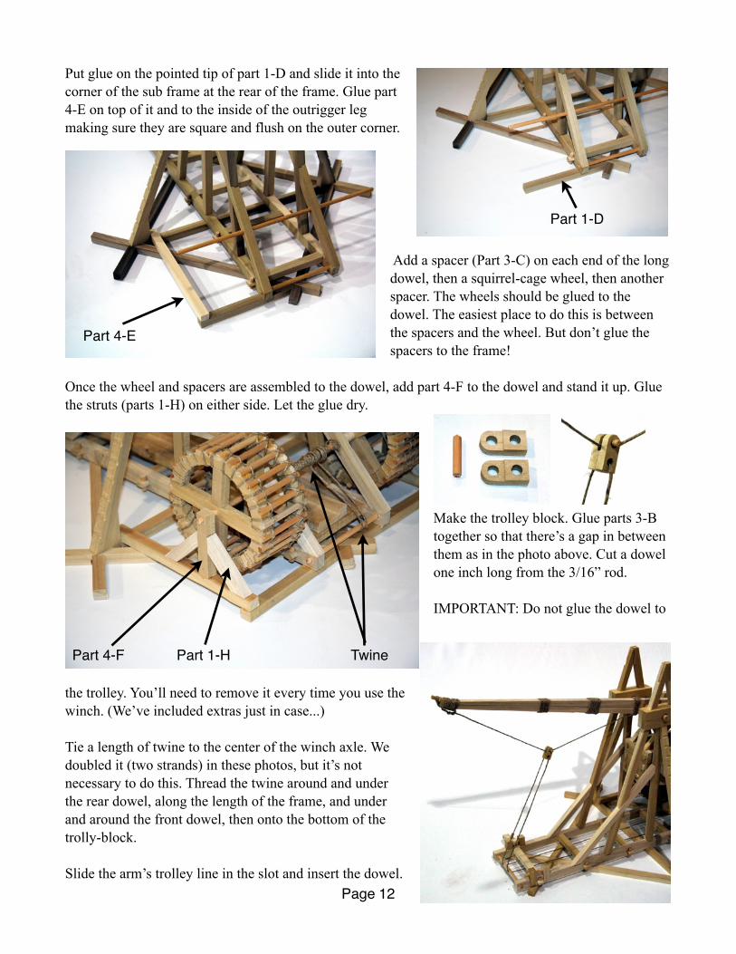
Put glue on the pointed tip of part 1-D and slide it into the corner of the sub frame at the rear of the frame. Glue part 4-E on top of it and to the inside of the outrigger leg making sure they are square and flush on the outer corner.
Add a spacer (Part 3-C) on each end of the long dowel, then a squirrel-cage wheel, then another spacer. The wheels should be glued to the dowel. The easiest place to do this is between the spacers and the wheel. But don’t glue the spacers to the frame!
Once the wheel and spacers are assembled to the dowel, add part 4-F to the dowel and stand it up. Glue the struts (parts 1-H) on either side. Let the glue dry.
Make the trolley block. Glue parts 3-B together so that there’s a gap in between them as in the photo above. Cut a dowel one inch long from the 3/16” rod.
IMPORTANT: Do not glue the dowel to
the trolley. You’ll need to remove it every time you use the winch. (We’ve included extras just in case...)
Tie a length of twine to the center of the winch axle. We doubled it (two strands) in these photos, but it’s not necessary to do this. Thread the twine around and under the rear dowel, along the length of the frame, and under and around the front dowel, then onto the bottom of the trolly-block.
Slide the arm’s trolley line in the slot and insert the dowel.Page 12
Part 1-D
Part 4-E
Part 4-F Part 1-H Twine
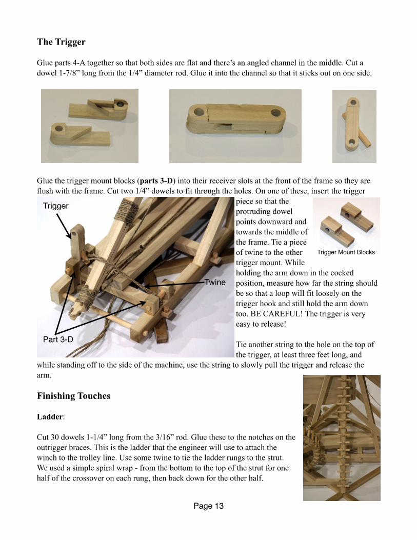
The Trigger
Glue parts 4-A together so that both sides are flat and there’s an angled channel in the middle. Cut a dowel 1-7/8” long from the 1/4” diameter rod. Glue it into the channel so that it sticks out on one side.
Glue the trigger mount blocks (parts 3-D) into their receiver slots at the front of the frame so they are flush with the frame. Cut two 1/4” dowels to fit through the holes. On one of these, insert the trigger
piece so that the protruding dowel points downward and towards the middle of the frame. Tie a piece of twine to the other trigger mount. While holding the arm down in the cocked position, measure how far the string should be so that a loop will fit loosely on the trigger hook and still hold the arm down too. BE CAREFUL! The trigger is very easy to release!
Tie another string to the hole on the top of the trigger, at least three feet long, and
while standing off to the side of the machine, use the string to slowly pull the trigger and release the arm.
Finishing Touches
Ladder:
Cut 30 dowels 1-1/4” long from the 3/16” rod. Glue these to the notches on the outrigger braces. This is the ladder that the engineer will use to attach the winch to the trolley line. Use some twine to tie the ladder rungs to the strut. We used a simple spiral wrap - from the bottom to the top of the strut for one half of the crossover on each rung, then back down for the other half.
Page 13
Trigger
Twine
Part 3-D
Trigger Mount Blocks

Sling:
Poke 4 small holes in each end of the pouch leather about 3/4” from the end.
Thread a string through the holes and fold the leather into an M shape (below). Turn the pouch upside down and push the center out to get a perfect pouch shape. Tie the string tightly around the end of the pouch. Use a good square knot or better if you know knots.
fig. 29 fig. 30
Tie a loop about 1 inch in diameter on the other end of the sling line so that the total length from the edge of the pouch to the looped end measures 16 (sixteen) inches (including the loop - see color photo).
Tie another string to the other end of the sling-pouch and tie the end of it to the wrapped loop (the same one the trolley line is tied to, under the arm-tip. See page 8), so that the sling line measures 15 (fifteen) inches from the arm to the pouch. Make sure that the loop slips off the wooden pin easily. If not, sand the pin smooth and/or put some petroleum jelly on it to make help slip off easily. This is the release pin, and the loop needs to slip off it at just the right time to sling the missile optimally.
Counterweight:
Stack 40 pennies, and carefully place the stack in the counterweight box. Do this 17 more times (nine stacks in each half of the box). You can tape the pennies together with cellophane tape to make this easier. If you don’t want to use pennies, use whatever you like, but try to keep the weight as close to 4 pounds as possible (not including the weight of the wooden box.)
Page 14
16 inches 15 inches

Here is the counterweight box shown with pennies. We’ve removed one of the hanger struts for clarity and we’ve taped the pennies so they won’t jostle out of the box if we accidentally dry-fire the machine.
Trough:
The trough is not glued down. By shifting the trough left or right, and/or twisting it a bit, you can actually aim the trebuchet without having to move the base. Not really a big deal for a small model, but the full sized version was immobile. So shifting the trough was the only way to aim the machine towards the left or right. Shift left to shoot right, and vice versa.
Trough alignment: Straight shot Shoot left Shoot more left
Cocking and firing.
Pick a spot that is flat and level to set the machine on. Winch the arm down and set the trigger. BE VERY CAREFUL! The trigger is very easy to release! Stay clear of the path of the arm and counterweight, and carefully remove the trolley-block dowel pin. Set the winch line and trolley block to the side, away from the sling paths.
Put the sling-loop over the wooden pin and pull the sling back into the trough so that the lines are straight and not twisted (see photo next page). Place the projectile in the pouch so that the pouch goes over and under the projectile, not horizontally around it. Make sure the sling lines are straight and have no slack. The pin-loop line should be on bottom, and the line attached to the arm should be on top. The machine is now loaded and ready to shoot!
Page 15
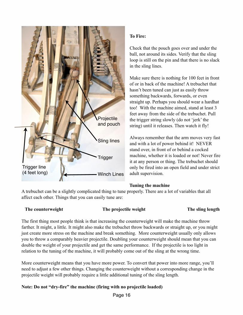
To Fire:
Check that the pouch goes over and under the ball, not around its sides. Verify that the sling loop is still on the pin and that there is no slack in the sling lines.
Make sure there is nothing for 100 feet in front of or in back of the machine! A trebuchet that hasn’t been tuned can just as easily throw something backwards, forwards, or even straight up. Perhaps you should wear a hardhat too! With the machine aimed, stand at least 3 feet away from the side of the trebuchet. Pull the trigger string slowly (do not ‘jerk’ the string) until it releases. Then watch it fly!
Always remember that the arm moves very fast and with a lot of power behind it! NEVER stand over, in front of or behind a cocked machine, whether it is loaded or not! Never fire it at any person or thing. The trebuchet should only be fired into an open field and under strict adult supervision.
Tuning the machineA trebuchet can be a slightly complicated thing to tune properly. There are a lot of variables that all affect each other. Things that you can easily tune are: The counterweight The projectile weight The sling length
The first thing most people think is that increasing the counterweight will make the machine throw farther. It might, a little. It might also make the trebuchet throw backwards or straight up, or you might just create more stress on the machine and break something. More counterweight usually only allows you to throw a comparably heavier projectile. Doubling your counterweight should mean that you can double the weight of your projectile and get the same performance. If the projectile is too light in relation to the tuning of the machine, it will probably come out of the sling at the wrong time.
More counterweight means that you have more power. To convert that power into more range, you’ll need to adjust a few other things. Changing the counterweight without a corresponding change in the projectile weight will probably require a little additional tuning of the sling length.
Note: Do not “dry-fire” the machine (firing with no projectile loaded)
Page 16
Projectile and pouch
Sling lines
Trigger
Winch LinesTrigger line(4 feet long)

The sling length:
Watch the missile very carefully while firing the machine. If it flies in a high lob, the sling probably needs to be shorter. To make it shorter you can just tie knots in both sides of the sling. This is a great way to make fine adjustments in the sling length.
If the missile flies low to the ground and not very far, a longer sling should make it fly higher, and therefore farther. (to a point...)
How to calculate your range efficiency:
The range efficiency is a measure of how well your machine converts all the energy available to it into throwing the ball. It’s really simple.
The ball travels in an arc when it’s hurled. There are two components to this arc, the vertical (how high it goes) and the horizontal (how far it goes). They relate to each other by the launch angle of the ball.
Using the physics of ballistic motion, gravity, and some trigonometry, we’ve derived this equation for the maximum theoretical range a machine like this can throw.
2 * (CW * drop) / P = Theoretical range.
CW is the weight of your total counterweight, including the box. The drop is the number of feet it falls when firing. This center of mass for the counterweight in this kit drops about 4.5 inches from highest point to lowest. If you have 4.5 lbs of counterweight, your available energy is 4.5 lbs * 4.5 inches = 20.25 inch-pounds of energy.
Multiply by 2, and then divide by P (the weight of your projectile). If your projectile is 0.2 ounces (0.0125 lbs), your maximum theoretical range is (20.25 * 2) inch-pounds / 0.0125 = 3240 inches, or 120 feet, IF you have a 100% efficient machine! The theoretical range is never really possible though. Most machines are never more than about 50% efficient due to things like friction, air resistance, non-perfect release angles, compression and elasticity of the various parts, etc., so your maximum realistic range is about half (50%) of your maximum theoretical range. Or:
CW * drop / P = realistic maximum range.
Now that you know the realistic and theoretical range of your machine, you can calculate your efficiency! If you calculate your theoretical range with the CW and projectile weights you have, then measure the actual distance of your shot, your efficiency is
Actual measured range / Theoretical range * 100 = percent efficiencyActual measured range / Realistic range * 100 = percent effectiveness
By using trial and error, careful observation and analysis, careful tuning can make your trebuchet do better than 50% efficiency. Work with it and see how much you can get out of this machine!
Page 17

Scale Models of Historical Figures:Cut out and glue to both sides of the wooden figure-forms (parts 1-K and 4-C).
Page 18


![Contentschordstrum.com/pdf/trebuchet/trebuchet new songs 02aug.pdf · 2017. 8. 2. · Sous le Ciel de Paris, Juliette Gréco Top [Gm] Sous le ciel de Paris s'envole une chanson [Cm]](https://img.pdfslide.tips/doc/110x75/6115e707b2e5a6058374802f/new-songs-02augpdf-2017-8-2-sous-le-ciel-de-paris-juliette-grco-top-gm.jpg)