Embed Size (px)
Citation preview

Thermodynamics of solids5. Unary systems
Kwangheon ParkKyung Hee University
Department of Nuclear Engineering
2
5.1. Unary heterogeneous system‐definition
Unary system: one component system. Unary heterogeneous system: one component with several phases
(water and ice, water‐ice‐steam at triple point of H2O, solid and liquid iron during melting)
H2O
Carbon
Copper
Allotropy: (Greek ʺotherʺ + ʺgrowʺ) is the property of some chemical elements to exist in two or more different forms, known as allotropes of these elements.
5.1. Unary heterogeneous system: definition
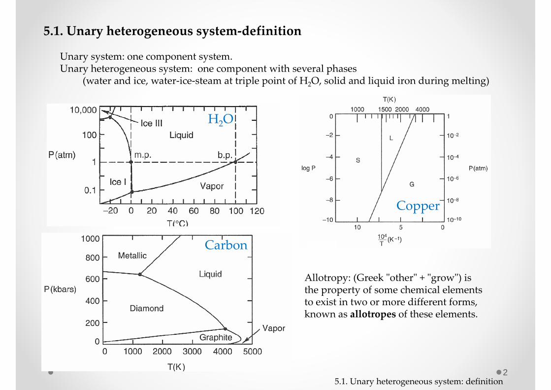
35.2. Gibbs free energy in a unary system
Unary system: one component system. Gibbs phase rule gives,
Hence, maximum number of phases in a unary system is 3.
(for one component system, 1)where : degree of freedom, : no. of components, : no. of phases
2 3 cf c p
f c p p
system
G(T,P,n)
( , , )dG T P n SdT VdP dn
,
where : chemical potential T P
Gn
Let g as a molar Gibbs free energy (J/mol),
, ,
then,( )
T P T P
G ng gn n
In a unary system, the chemical potential of the component in any state is identical with the molar Gibbs free energy for that state.
5.2. Gibbs free energy in a unary system
4
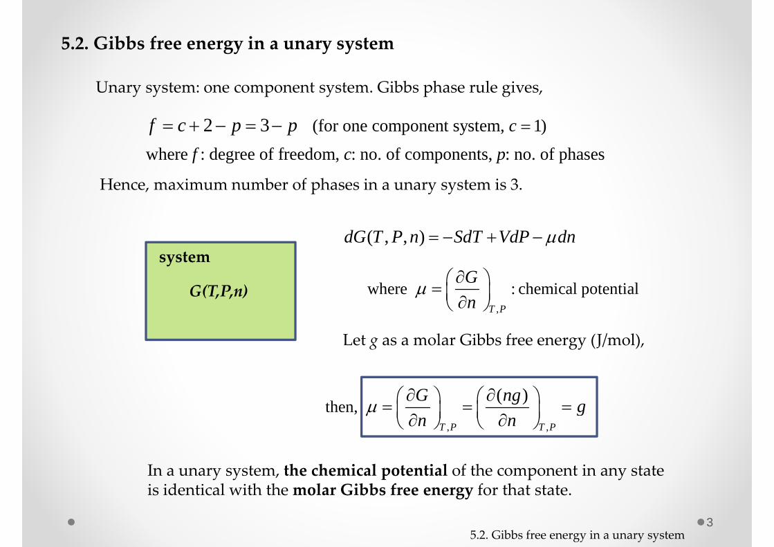
( , , n ) ( , , n )G G T P G T P
( , , )T P n
( , , )T P n TSYS=TSURR
PSYS=PSURR
Since ( , , )dG T P n SdT VdP dn
dG dG dG dn dn
At constant T and constant P,
And 0Totdn dn dn
At equilibrium, dG=0 (the minimum).
( ) 0dG dn dn dn
If two (or three) phases coexist at equilibrium,
if third phase coexists ( )
5.2. Gibbs free energy in a unary system
Equilibrium condition between 2 or 3 phases
( , )T T P P
(also , )T T P P

5
H2O
TTbTm
g
gICE
gLIQgVAP
Phase stability
Icestable
Liquid stableVaporstable
Equilibrium
Molar free energy
at 1atm.
g h Ts
ICE LIQ VAPs s s
5.2. Gibbs free energy in a unary system
6
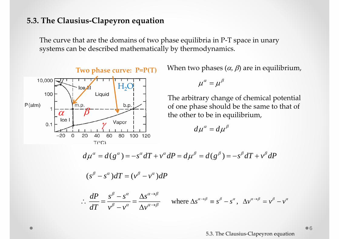
5.3. The Clausius‐Clapeyron equation
The curve that are the domains of two phase equilibria in P‐T space in unary systems can be described mathematically by thermodynamics.
H2O
Two phase curve: P=P(T)
When two phases () are in equilibrium,
The arbitrary change of chemical potential of one phase should be the same to that of the other to be in equilibrium,
d d
( ) ( )d d g s dT v dP d d g s dT v dP
( ) ( )s s dT v v dP
where , s s s v v vdP s s sdT v v v
5.3. The Clausius‐Clapeyron equation

7
dP hdT T v
Since,
g h s T g h s T
( 0 if transformation from solid to liquid) h h h s s sT T
Homework 5.1. Draw G vs. T graph for three phases of H2O at the triple point.
Homework 5.2. Calculate the slope of the curve indicating the equilibrium between water and ice at 1 atm. And find the slope of the curve between water and steam at 1 atm. Slope = dP/dT.
where : latent heat for transformation from to phase .h
Homework 5.3. Calculate the change of melting temperature of ice when the pressure is applied from 1 atm to 100 atm. What is the boiling temperature when we apply 10 atm to the water under heating?
use T vT Ph
5.3. The Clausius‐Clapeyron equation

8
Vaporization and sublimation curves
H2O dP hdT T v
when is a vapor phase. v v v v
Let’s assume the vapor as an ideal gas.RTv vP
2= dP h h PRTdT RTTP
2 dP h dTP RT
constantln hPRT
0 hRTP P e
5.3. The Clausius‐Clapeyron equation
9
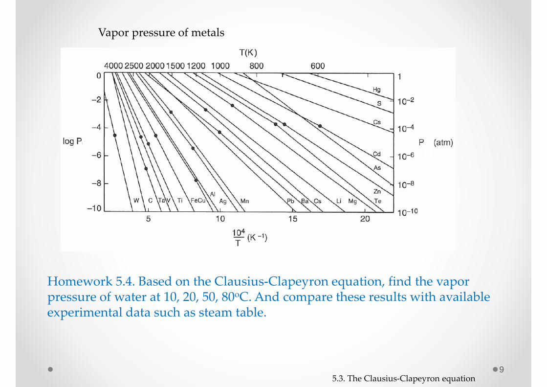
Vapor pressure of metals
Homework 5.4. Based on the Clausius‐Clapeyron equation, find the vapor pressure of water at 10, 20, 50, 80oC. And compare these results with available experimental data such as steam table.
5.3. The Clausius‐Clapeyron equation
10
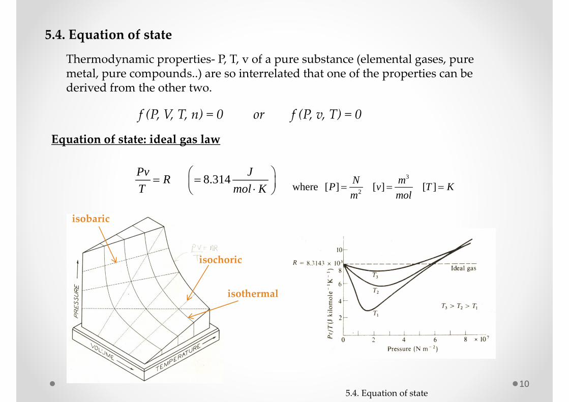
5.4. Equation of state
Thermodynamic properties‐ P, T, v of a pure substance (elemental gases, pure metal, pure compounds..) are so interrelated that one of the properties can be derived from the other two.
f (P, V, T, n) = 0 or f (P, v, T) = 0
8.314Pv JRT mol K
3
2where [ ] [ ] [ ]N mP v T Km mol
isobaric
isothermal
isochoric
Equation of state: ideal gas law
5.4. Equation of state
11
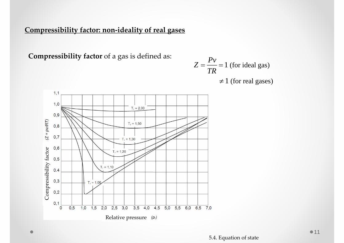
Compressibility factor: non‐ideality of real gases
(for ideal gas)
(for real gases)
1
1
PvZTR
Com
pressibility factor
Relative pressure
Compressibility factor of a gas is defined as:
5.4. Equation of state
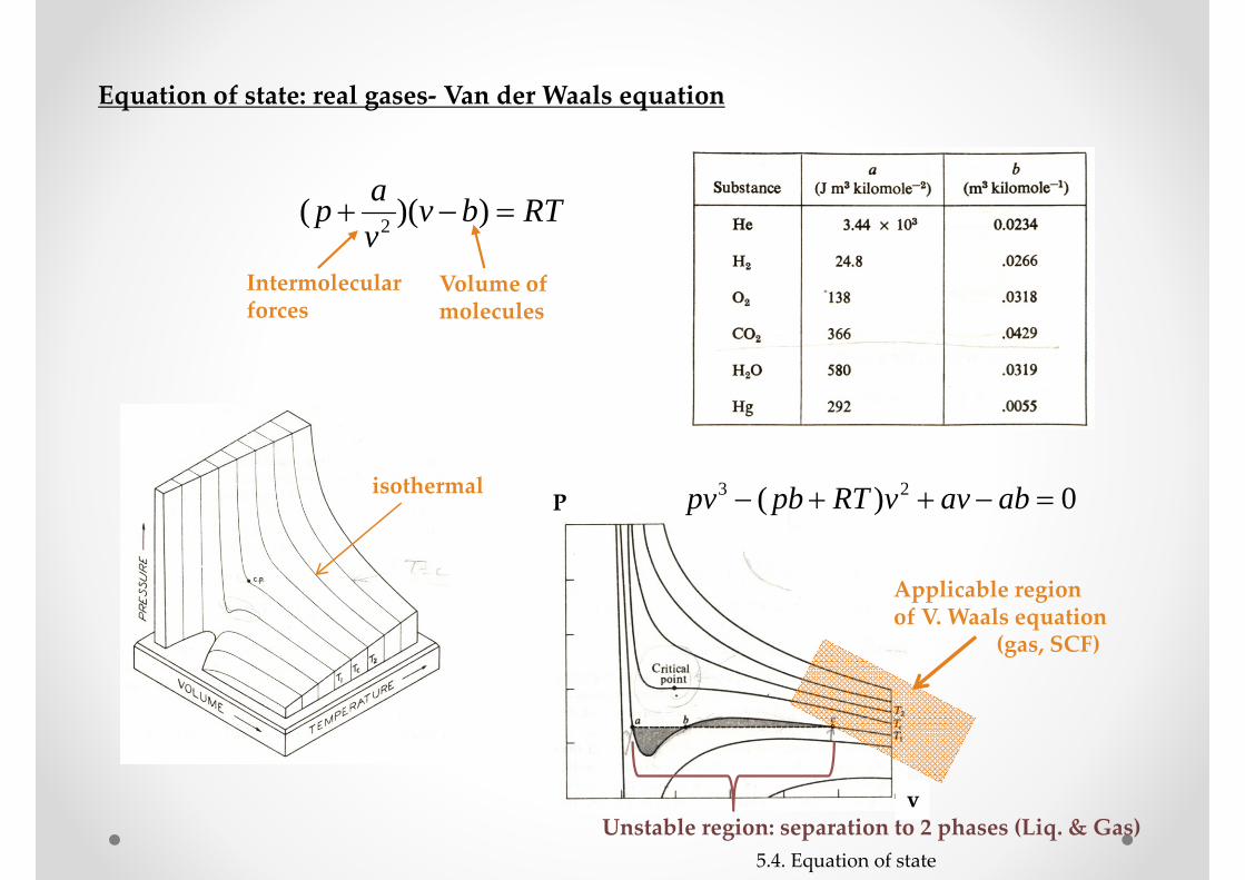
Unstable region: separation to 2 phases (Liq. & Gas)
P
v
Equation of state: real gases‐ Van der Waals equation
Intermolecularforces
Volume ofmolecules
RTbvvap ))(( 2
isothermal 0)( 23 abavvRTpbpv
5.4. Equation of state
Applicable regionof V. Waals equation
(gas, SCF)
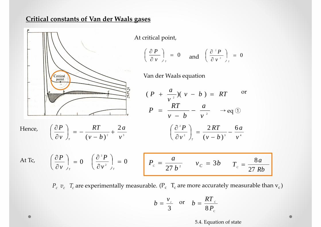
At critical point,
0
TvP
02
2
TvP
and
Van der Waals equation
RTbvvaP ))((
2
or
2va
bvRTP
→ eq ①
Hence, 32
2)( v
abv
RTvP
T
432
2 6)(
2va
bvRT
vP
T
At Tc, 0
TvP 0
2
2
TvP
227 baPC bvC 3
RbaTC 27
8
Pc vc Tc are experimentally measurable.
3cvb
C
C
PRTb8
or
(Pc Tc are more accurately measurable than vc )
Critical constants of Van der Waals gases
5.4. Equation of state
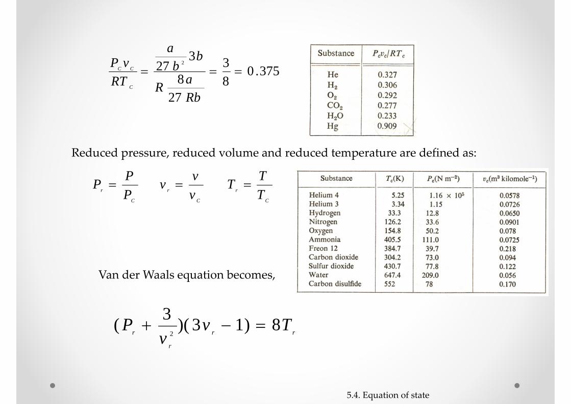
375.083
278
327 2
RbaR
bb
a
RTvP
C
CC
Reduced pressure, reduced volume and reduced temperature are defined as:
C
r PPP
C
r vvv
C
r TTT
rr
r
r Tvv
P 8)13)(3(2
Van der Waals equation becomes,
5.4. Equation of state
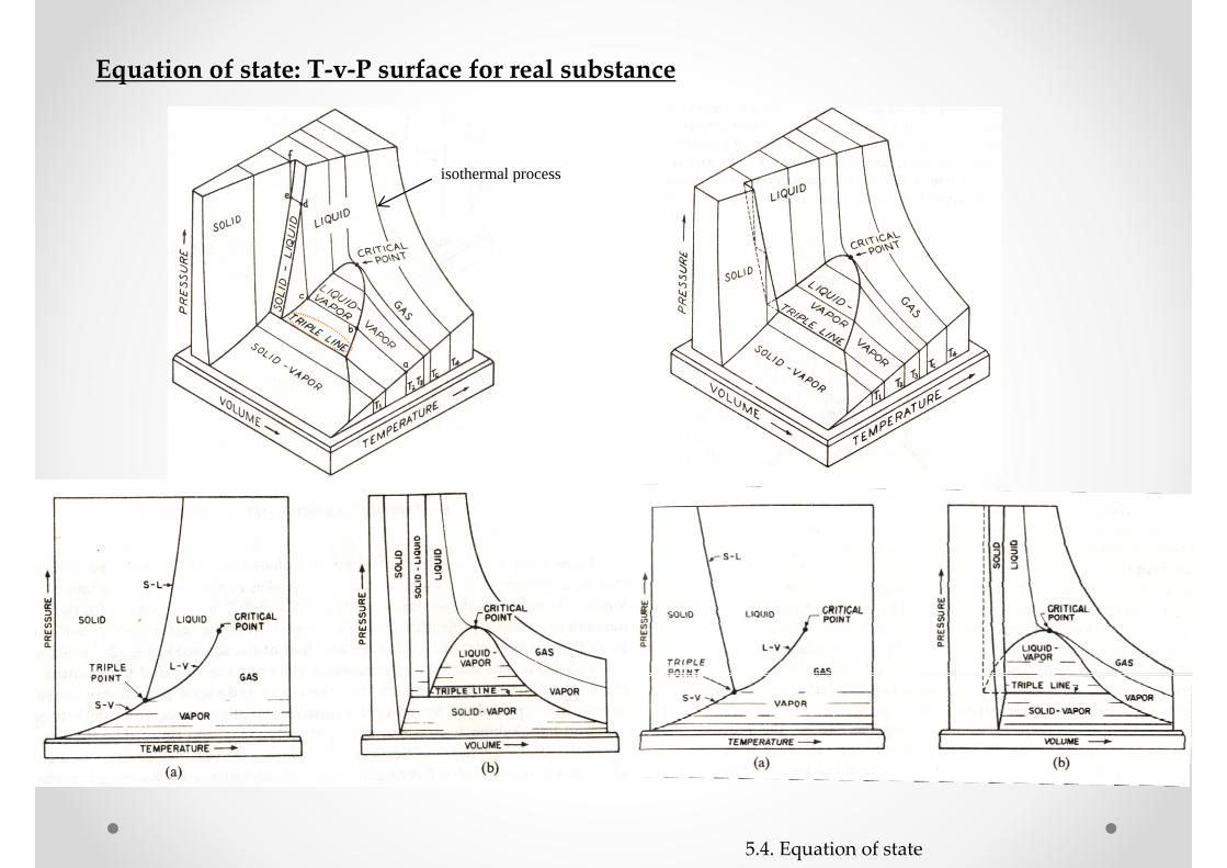
isothermal process
Equation of state: T‐v‐P surface for real substance
5.4. Equation of state

Triple-point data
PhaseSeparation
No PhaseSeparation
= 0.006 atm
5.4. Equation of state
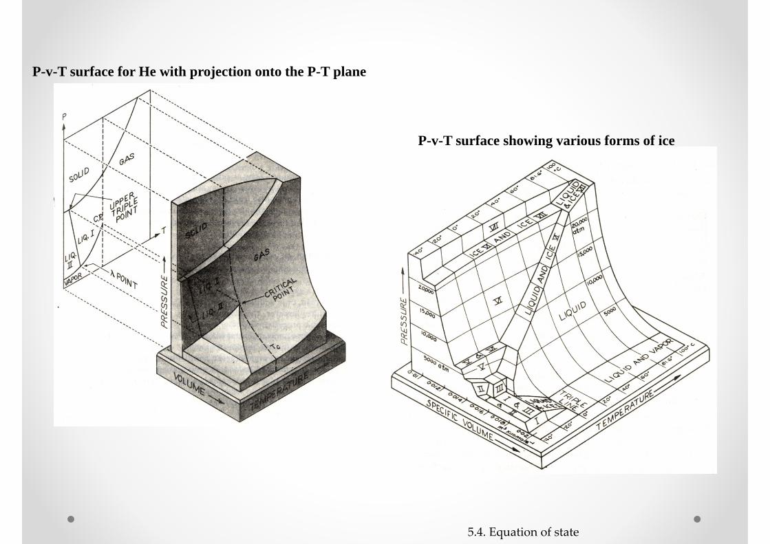
P-v-T surface for He with projection onto the P-T plane
P-v-T surface showing various forms of ice
5.4. Equation of state
18
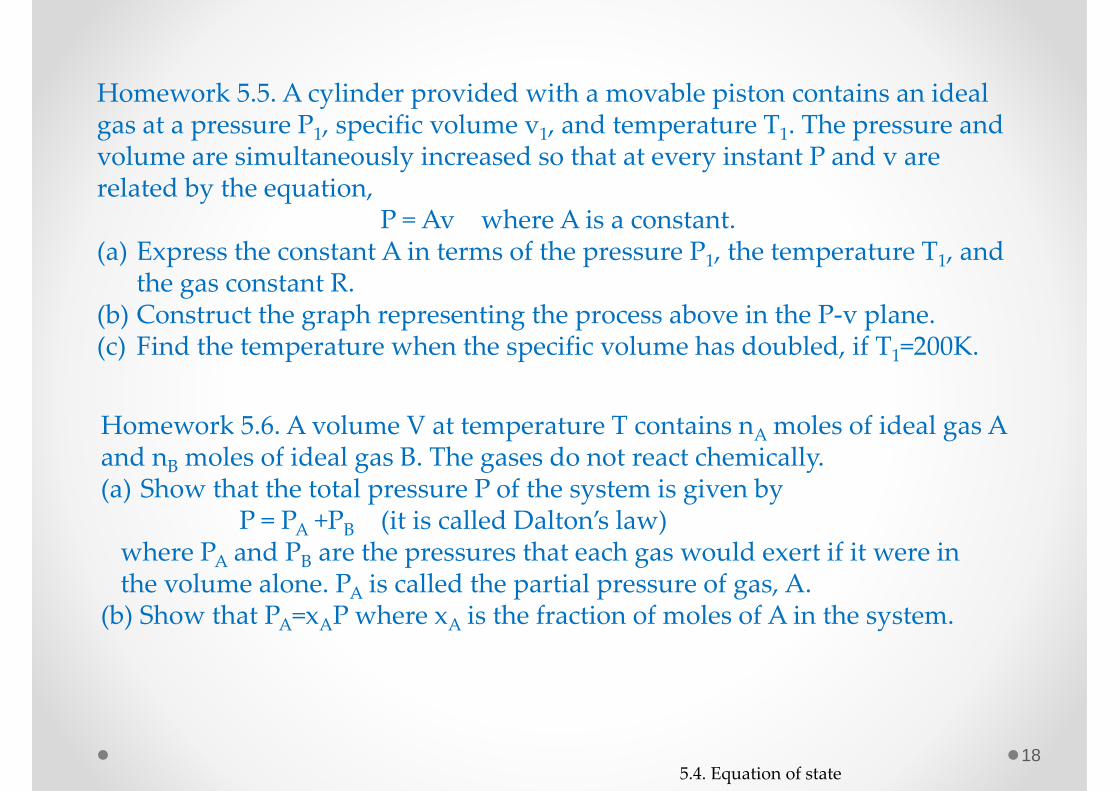
Homework 5.5. A cylinder provided with a movable piston contains an ideal gas at a pressure P1, specific volume v1, and temperature T1. The pressure and volume are simultaneously increased so that at every instant P and v are related by the equation,
P = Av where A is a constant.(a) Express the constant A in terms of the pressure P1, the temperature T1, and
the gas constant R.(b) Construct the graph representing the process above in the P‐v plane.(c) Find the temperature when the specific volume has doubled, if T1=200K.
Homework 5.6. A volume V at temperature T contains nAmoles of ideal gas A and nB moles of ideal gas B. The gases do not react chemically.(a) Show that the total pressure P of the system is given by
P = PA +PB (it is called Dalton’s law)where PA and PB are the pressures that each gas would exert if it were in the volume alone. PA is called the partial pressure of gas, A.
(b) Show that PA=xAP where xA is the fraction of moles of A in the system.
5.4. Equation of state

19
Stable and unstabe (metastable) equilibrium
a, b: thermodynamically stablec: metastable state due to NOT
forming liquid nuclides. It is called supercooled (gas) state.
e, f: thermodynamically stabled: metastable state due to NOT
forming gas nuclides in liquid.It is called superheated (liquid) state.
5.4. Equation of state
20
5.5. Joule – Thomson experiment
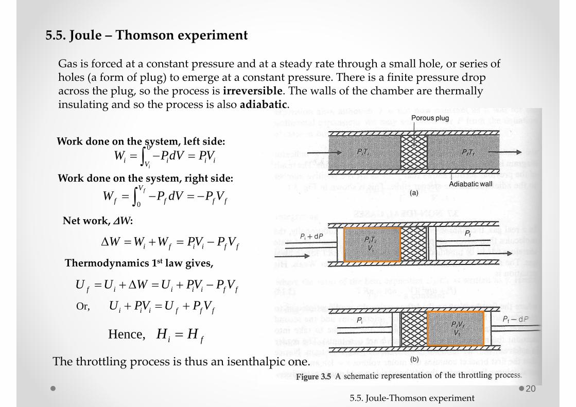
Gas is forced at a constant pressure and at a steady rate through a small hole, or series of holes (a form of plug) to emerge at a constant pressure. There is a finite pressure drop across the plug, so the process is irreversible. The walls of the chamber are thermally insulating and so the process is also adiabatic.
Work done on the system, left side:0
ii i i iV
W PdV PV Work done on the system, right side:
0
fV
f f f fW P dV P V Net work, W:
i f i i f fW W W PV P V
Thermodynamics 1st law gives,
Or,
f i i i i f f
i i i f f f
U U W U PV P V
U PV U P V
Hence, i fH H
The throttling process is thus an isenthalpic one.
5.5. Joule‐Thomson experiment
21
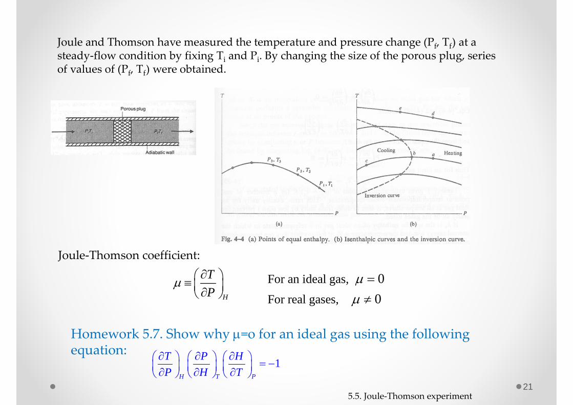
Joule and Thomson have measured the temperature and pressure change (Pf, Tf) at a steady‐flow condition by fixing Ti and Pi. By changing the size of the porous plug, series of values of (Pf, Tf) were obtained.
Joule‐Thomson coefficient:
H
TP
For an ideal gas,For real gases,
0 0
5.5. Joule‐Thomson experiment
Homework 5.7. Show why =o for an ideal gas using the following equation:
1H T P
T P HP H T
22
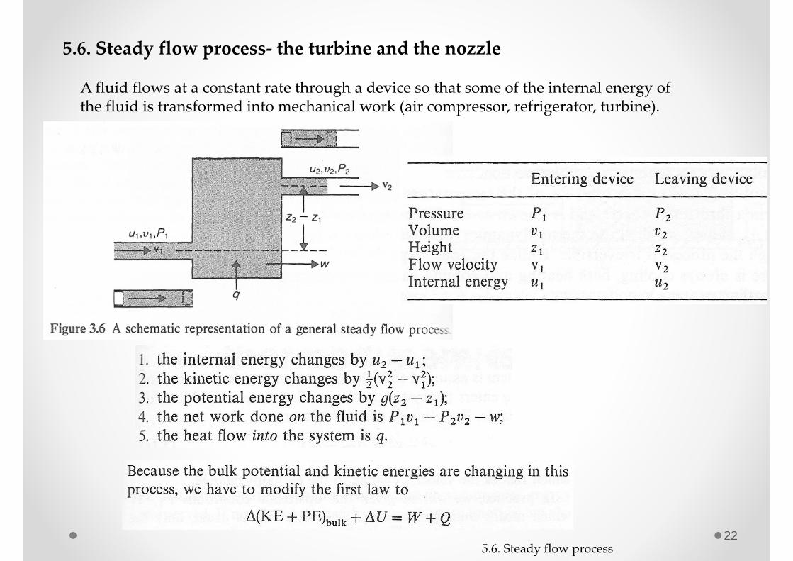
5.6. Steady flow process‐ the turbine and the nozzle
A fluid flows at a constant rate through a device so that some of the internal energy of the fluid is transformed into mechanical work (air compressor, refrigerator, turbine).
5.6. Steady flow process
23
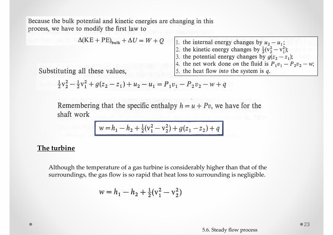
The turbine
Although the temperature of a gas turbine is considerably higher than that of the surroundings, the gas flow is so rapid that heat loss to surrounding is negligible.
5.6. Steady flow process
24
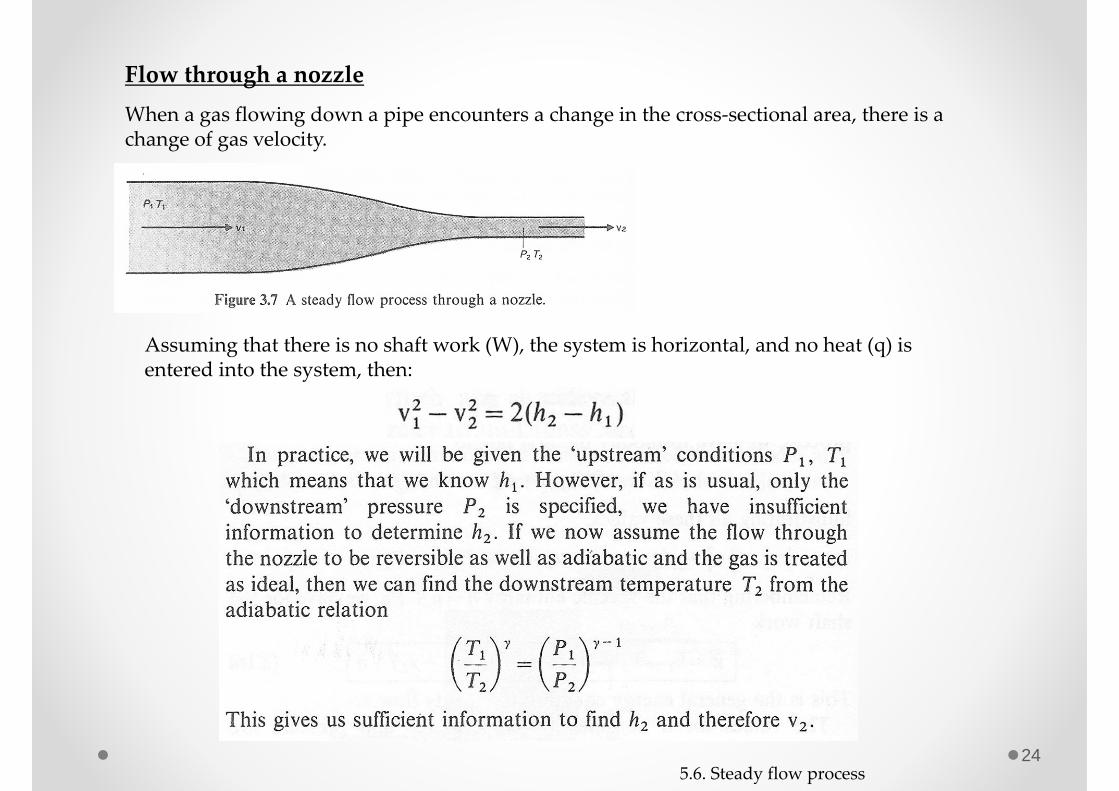
Flow through a nozzleWhen a gas flowing down a pipe encounters a change in the cross‐sectional area, there is a change of gas velocity.
Assuming that there is no shaft work (W), the system is horizontal, and no heat (q) is entered into the system, then:
5.6. Steady flow process
25
Homework 5.8. A steam turbine takes in steam at the rate of 600kg/h and its power output is 800 kW. Neglect any heat loss from the turbine. Find the change in the specific enthalpy of the steam as it passes through the turbine if,(a) the entrance and exit are at the same elevation and the entrance
and exit velocities are negligible.(b) the entrance velocity is 50 m/s and the exit velocity is 200 m/s, with
the outlet pipe being 2 m above the inlet.
5.6. Steady flow process
26
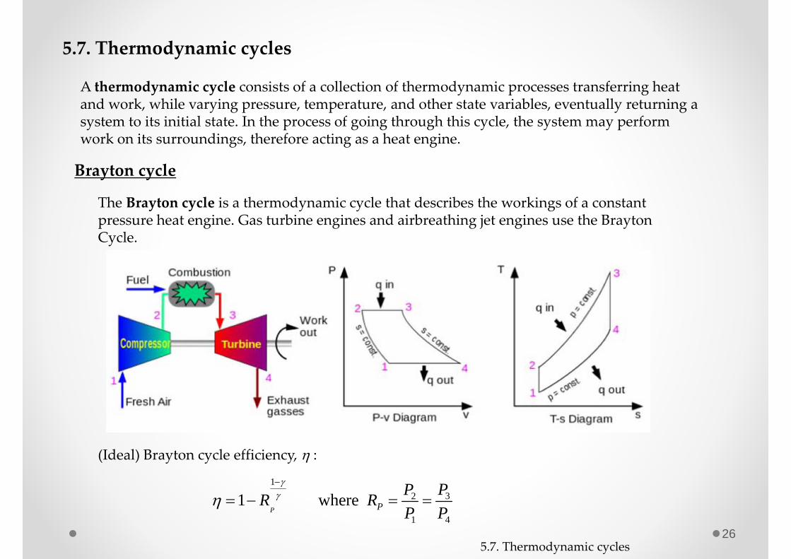
5.7. Thermodynamic cycles
A thermodynamic cycle consists of a collection of thermodynamic processes transferring heat and work, while varying pressure, temperature, and other state variables, eventually returning a system to its initial state. In the process of going through this cycle, the system may perform work on its surroundings, therefore acting as a heat engine.
The Brayton cycle is a thermodynamic cycle that describes the workings of a constant pressure heat engine. Gas turbine engines and airbreathing jet engines use the BraytonCycle.
Brayton cycle
(Ideal) Brayton cycle efficiency, :
132
1 4
1 where P P
PPR RP P
5.7. Thermodynamic cycles
27
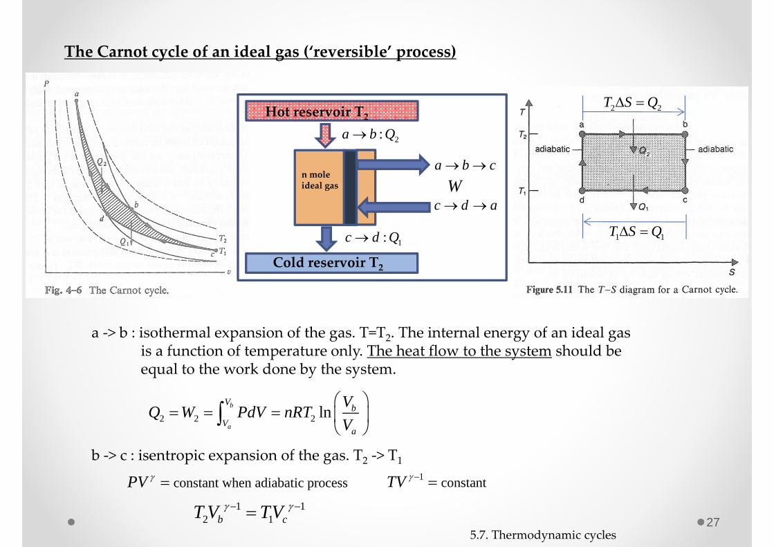
The Carnot cycle of an ideal gas (‘reversible’ process)
a ‐> b : isothermal expansion of the gas. T=T2. The internal energy of an ideal gas is a function of temperature only. The heat flow to the system should be equal to the work done by the system.
2 2 2 lnb
a
V bV
a
VQ W PdV nRTV
b ‐> c : isentropic expansion of the gas. T2 ‐> T1
constant when adiabatic processPV 1 constant TV 1 1
2 1b cT V TV
2 2T S Q
1 1T S Q
Hot reservoir T2
Cold reservoir T2
2:a b Q
1:c d Q
a b c
c d a
n moleideal gas W
5.7. Thermodynamic cycles

28
c ‐> d : isothermal compression of the gas. T=T1. The internal energy of an ideal gas is a function of temperature only. The heat flow to the surrounding should be equal to the work done by the surrounding on the system. (Q1>0)
1 1 1 lnd
c
V cV
d
VQ W PdV nRTV
d ‐> a : isentropic compression of the gas. T1 ‐> T2
1 11 2d aTV T V
1 1
2
1
d c
a b
V VTT V V
or, b c
a d
V VV V
2 2
1 1
Hence, Q TQ T
Total work done by the system after one cycle, W:
2 1
2 1
( )
W PdV TdS dU TdS dU TdS T S T S
Q Q
The efficiency of the Carnot cycle engine, :
2 1 2 2 2 1
2 1 1 1 1
= 1 1Q Q Q T T TWQ Q Q T T
No engine operating between two reservoirs can be more efficient than a Carnot engine operating between those same two reservoirs.
5.7. Thermodynamic cycles
29
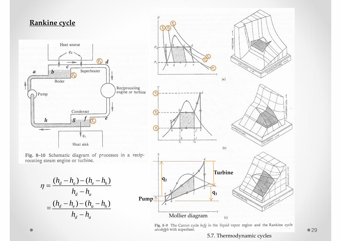
Rankine cycle
a bc
d
eh fg
Mollier diagram
q2
q1
Turbine
Pump
( ) ( )
( ) ( ) =
d a e h
d a
d e a h
d a
h h h hh h
h h h hh h
5.7. Thermodynamic cycles
30
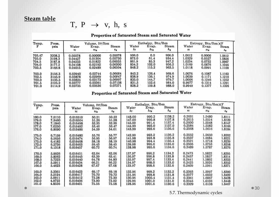
Steam tableT, P v, h, s
5.7. Thermodynamic cycles
31
Homework 5.9. Derive the efficiency of the Brayton cycle using the following equations;
qin= h3 ‐ h2 = CP (T3‐T2) qout= h4 – h1 = CP (T4‐T1)
out in
in
q qq
1 const. if the process is adiabatic.T P
Homework 5.10. A Caront engine can be made to operate as a refrigerator. Explain in detail, with the aid of (a) a pressure‐volume diagram, (b) an enthalpy‐entropy diagram, all the processes which occur during a complete cycle or operation. This refrigerator freezes water at 0oC and heat from the working substance is discharged into a tank containing water maintained at 20oC. Determine the minimum amount of work required to freeze 3 kg of water. (1048)
5.7. Thermodynamic cycles
Homework 5.11. Draw a Mollier diagram and a T‐S diagram of the Rankine cycle for the Korean standard nuclear power plant (OPR1000) using FSAR and the steam table. And calculate the efficiency of the cycle.

32
5.8. Phase transformation classified according to order
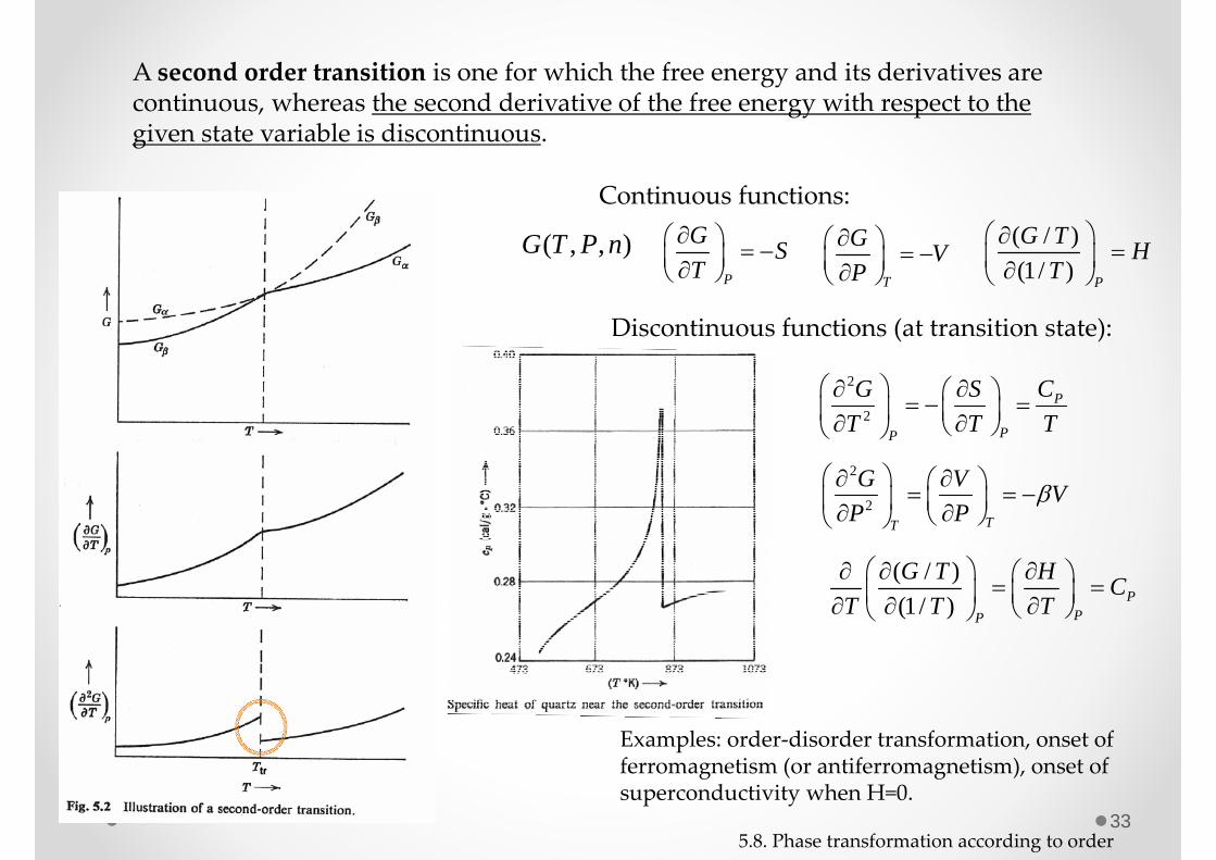
A first order transition is one for which the free energy as a function of a given state variable (V, P, T) is continuous, whereas the first derivative of the free energy with respect to the given state variable is discontinuous.
5.8. Phase transformation according to order
P
G ST
Continuous functions:
( , , )G T P n
Discontinuous functions (at transition state):
T
G VP
( / )(1/ ) P
G T HT
Discontinuity ofthe first derivative of G
Examples: fusion, vaporization and allotropic transformations
33
A second order transition is one for which the free energy and its derivatives are continuous, whereas the second derivative of the free energy with respect to the given state variable is discontinuous.
5.8. Phase transformation according to order
P
G ST
Continuous functions:
( , , )G T P n
Discontinuous functions (at transition state):
T
G VP
( / )(1/ ) P
G T HT
Examples: order‐disorder transformation, onset of ferromagnetism (or antiferromagnetism), onset of superconductivity when H=0.
2
2P
PP
CG ST T T
2
2TT
G V VP P
( / )(1/ ) P
PP
G T H CT T T
345.9. Gibbs free energy in a unary system
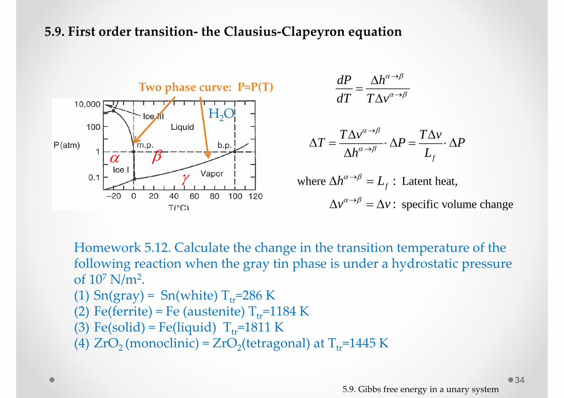
5.9. First order transition‐ the Clausius‐Clapeyron equation
H2O
Two phase curve: P=P(T)
dP hdT T v
f
T v T vT P Ph L
where Latent heat,
specific volume change
:
: fh L
v v
Homework 5.12. Calculate the change in the transition temperature of the following reaction when the gray tin phase is under a hydrostatic pressure of 107 N/m2.(1) Sn(gray) = Sn(white) Ttr=286 K(2) Fe(ferrite) = Fe (austenite) Ttr=1184 K(3) Fe(solid) = Fe(liquid) Ttr=1811 K(4) ZrO2 (monoclinic) = ZrO2(tetragonal) at Ttr=1445 K
35
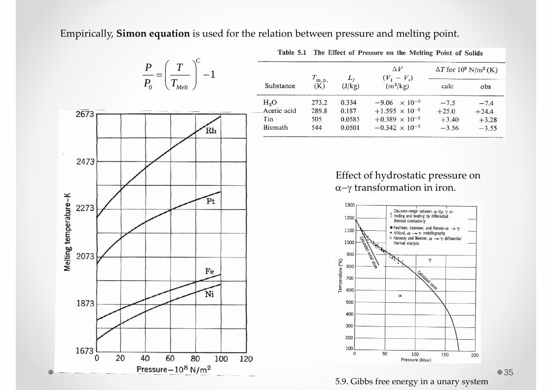
Empirically, Simon equation is used for the relation between pressure and melting point.
0
1C
Melt
P TP T
Effect of hydrostatic pressure on transformation in iron.
5.9. Gibbs free energy in a unary system
36
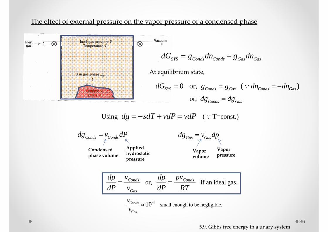
The effect of external pressure on the vapor pressure of a condensed phase
SYS Conds Conds Gas GasdG g dn g dn
At equilibrium state,
0 or, ( )SYS Conds Gas Conds GasdG g g dn dn
Using ( T=const.) dg sdT vdP vdP
or, Conds Gasdg dg
Conds Condsdg v dP
Applied hydrostatic pressure
Condensedphase volume
Gas Gasdg v dp
Vaporvolume
Vaporpressure
or, if an ideal gas. Conds Conds
Gas
v pvdp dpdP v dP RT
-4 small enough to be negligible.10 Conds
Gas
vv
5.9. Gibbs free energy in a unary system