Embed Size (px)
DESCRIPTION
Emphasis on Thermal Control of Electronics
Citation preview
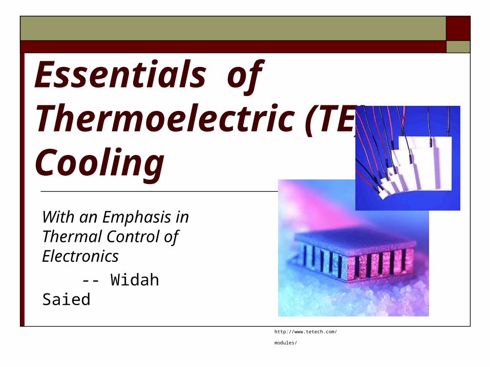
Essentials of Thermoelectric (TE) Cooling With an Emphasis in Thermal Control of Electronics
-- Widah Saied
http://www.tetech.com/modules/
Outline Introduction and Purpose
Why use TE coolers Disadvantages Which industries use TE cooling and their applications.
Basic Principles Semiconductor P and N Type Doping TE Design
Figure of` merit Thermoelectric materials Condensation TE performance Design methodology Improving performance
TE Electronics Cooling Applications TE Cooling Alternatives
Why are TE Coolers Used for Cooling? No moving parts make them very reliable; approximately 105
hrs of operation at 100 degrees Celsius, longer for lower temps (Goldsmid,1986).
Ideal when precise temperature control is required. Ability to lower temperature below ambient. Heat transport controlled by current input. Able to operate in any orientation. Compact size make them useful for applications where size
or weight is a constraint. Ability to alternate between heating and cooling. Excellent cooling alternative to vapor compression coolers
for systems that are sensitive to mechanical vibration.
(TE Tecnology, Inc., http://www.tetech.com/techinfo/)
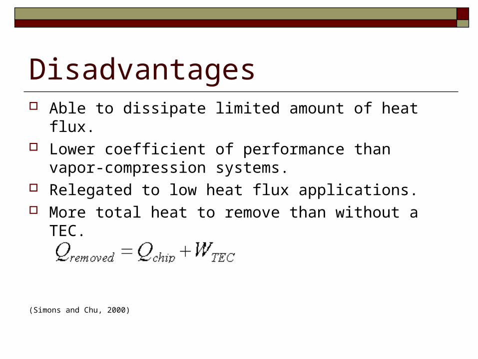
Disadvantages Able to dissipate limited amount of heat flux. Lower coefficient of performance than vapor-
compression systems. Relegated to low heat flux applications. More total heat to remove than without a TEC.
(Simons and Chu, 2000)
Which Industries Use TE Cooling? Electronic Medical Aerospace Telecommunications
(TE Tecnology, Inc., http://www.tetech.com/techinfo/)
What are Some Applications? Cooling: Electronic enclosures Laser diodes Laboratory instruments Temperature baths Refrigerators Telecommunications equipment Temperature control in missiles and space systems Heat transport ranges vary from a few milliwatts to several
thousand watts, however, since the efficiency of TE devices are low, smaller heat transfer applications are more practical.
(TE Tecnology, Inc.,http://www.tetech.com/techinfo/)
Basic Principles Peltier Effect- when a voltage or DC current is applied to two
dissimilar conductors, a circuit can be created that allows for continuous heat transport between the conductor’s junctions. The Seebeck Effect- is the reverse of the Peltier Effect. By applying heat to two different conductors a current can be generated. The Seebeck Coefficient is given by:
where is the electric field.
The current is transported through charge carriers (opposite the hole flow or with electron flow).
Heat transfer occurs in the direction of charge carrier movement.
(Tellurex, www.tellurex.com)
dxdTx
/
Basic Principles
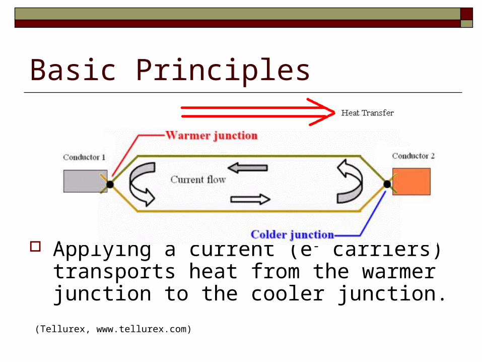
Applying a current (e- carriers) transports heat from the warmer junction to the cooler junction.(Tellurex, www.tellurex.com)
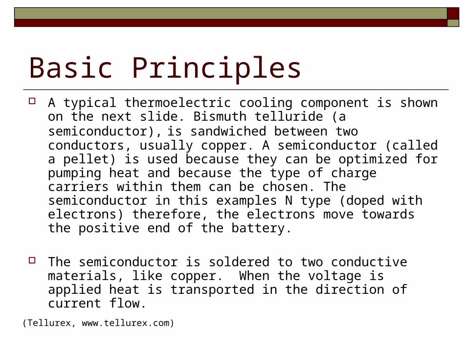
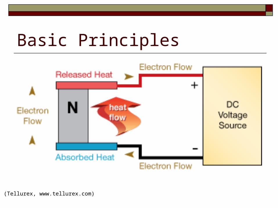
Basic Principles A typical thermoelectric cooling component is shown on the
next slide. Bismuth telluride (a semiconductor), is sandwiched between two conductors, usually copper. A semiconductor (called a pellet) is used because they can be optimized for pumping heat and because the type of charge carriers within them can be chosen. The semiconductor in this examples N type (doped with electrons) therefore, the electrons move towards the positive end of the battery.
The semiconductor is soldered to two conductive materials, like copper. When the voltage is applied heat is transported in the direction of current flow.
(Tellurex, www.tellurex.com)
Basic Principles
(Tellurex, www.tellurex.com)
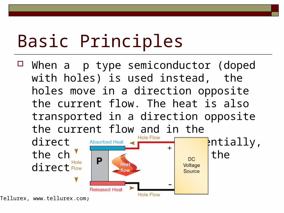
Basic Principles When a p type semiconductor (doped with holes) is
used instead, the holes move in a direction opposite the current flow. The heat is also transported in a direction opposite the current flow and in the direction of the holes. Essentially, the charge carriers dictate the direction of heat flow.
(Tellurex, www.tellurex.com)
Method of Heat Transport Electrons can travel freely in the copper conductors but not so freely in
the semiconductor. As the electrons leave the copper and enter the hot-side of the p-type,
they must fill a "hole" in order to move through the p-type. When the electrons fill a hole, they drop down to a lower energy level and release heat in the process.
Then, as the electrons move from the p-type into the copper conductor on the cold side, the electrons are bumped back to a higher energy level and absorb heat in the process.
Next, the electrons move freely through the copper until they reach the cold side of the n-type semiconductor. When the electrons move into the n-type, they must bump up an energy level in order to move through the semiconductor. Heat is absorbed when this occurs.
Finally, when the electrons leave the hot-side of the n-type, they can move freely in the copper. They drop down to a lower energy level and release heat in the process.
http://www.tetech.com/techinfo/#1
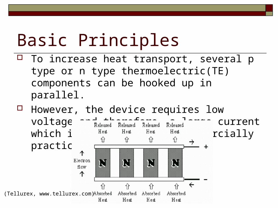
Basic Principles To increase heat transport, several p type or n type
thermoelectric(TE) components can be hooked up in parallel.
However, the device requires low voltage and therefore, a large current which is too great to be commercially practical.
(Tellurex, www.tellurex.com)
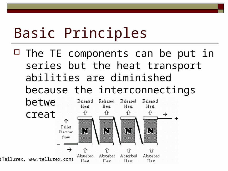
Basic Principles The TE components can be put in series but
the heat transport abilities are diminished because the interconnectings between the semiconductor creates thermal shorting.
(Tellurex, www.tellurex.com)
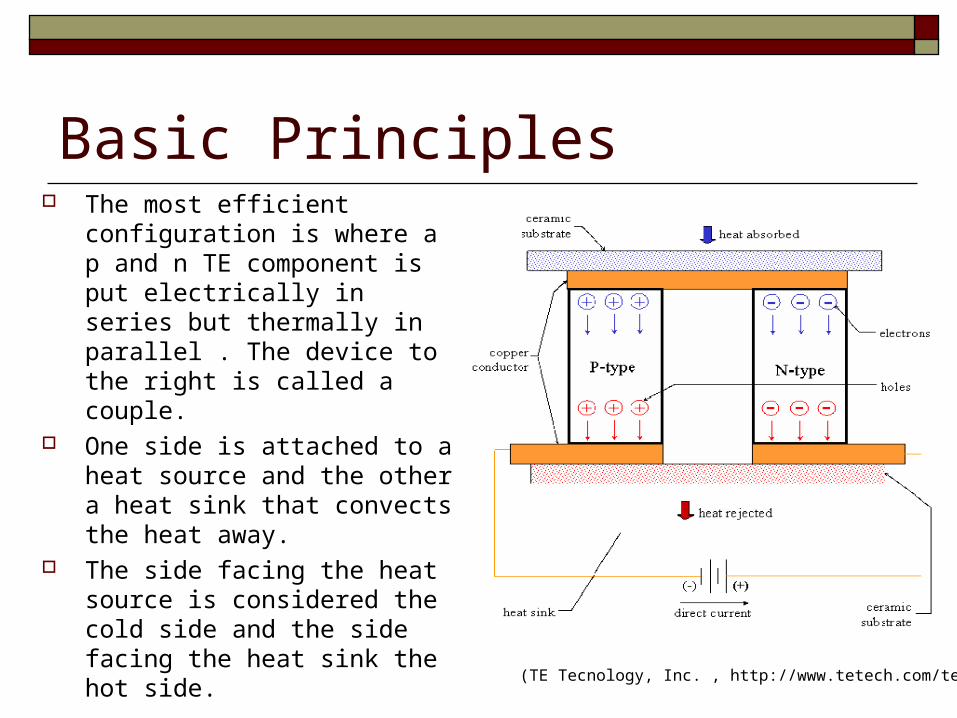
Basic Principles The most efficient
configuration is where a p and n TE component is put electrically in series but thermally in parallel . The device to the right is called a couple.
One side is attached to a heat source and the other a heat sink that convects the heat away.
The side facing the heat source is considered the cold side and the side facing the heat sink the hot side.
(TE Tecnology, Inc. , http://www.tetech.com/techinfo/)
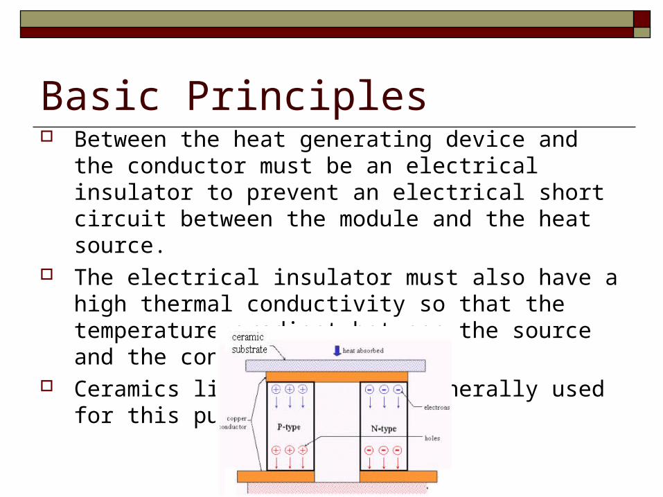
Basic Principles Between the heat generating device and the conductor must
be an electrical insulator to prevent an electrical short circuit between the module and the heat source.
The electrical insulator must also have a high thermal conductivity so that the temperature gradient between the source and the conductor is small.
Ceramics like alumina are generally used for this purpose. (Rowe, 1995).
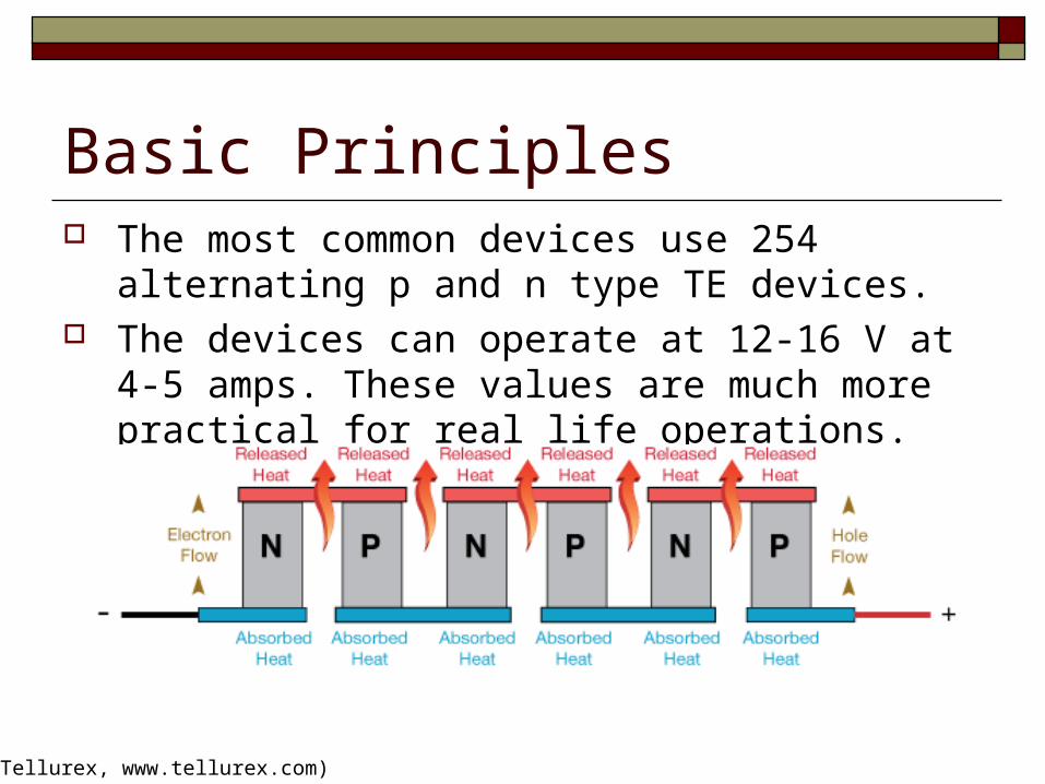
Basic Principles The most common devices use 254 alternating p and n
type TE devices. The devices can operate at 12-16 V at 4-5 amps. These
values are much more practical for real life operations.
(Tellurex, www.tellurex.com)
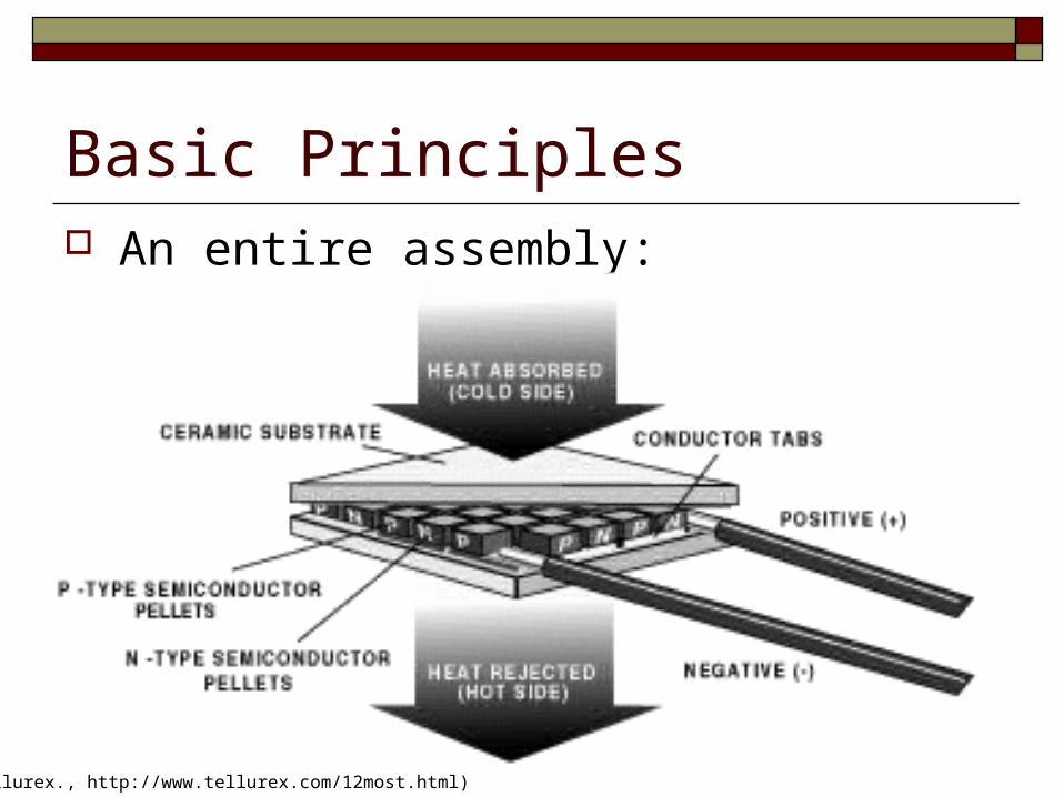
Basic Principles An entire assembly:
(Tellurex., http://www.tellurex.com/12most.html)
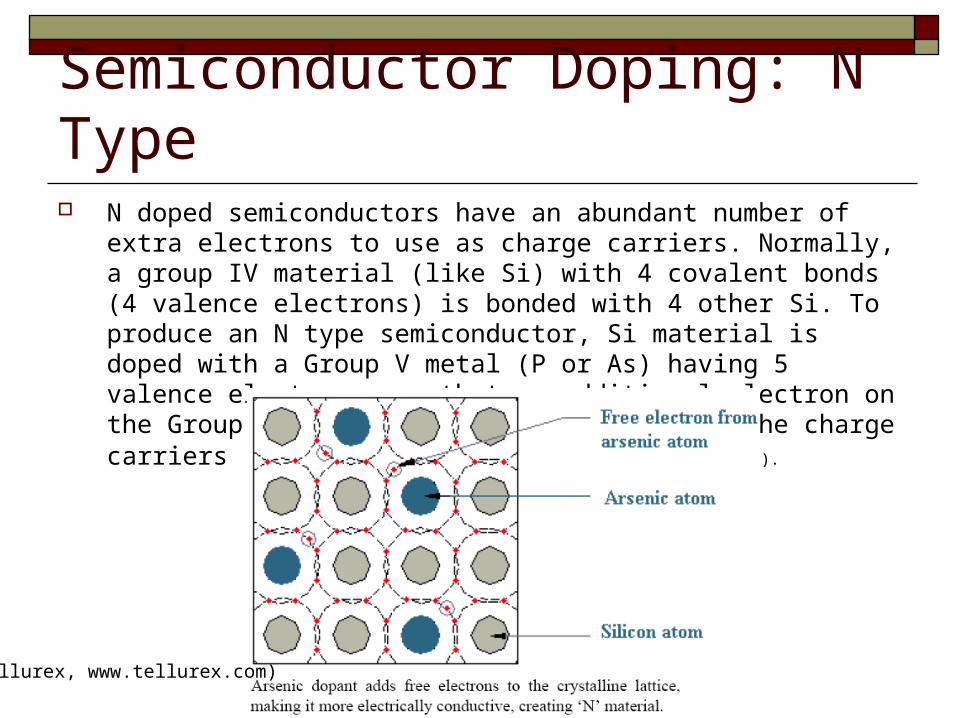
Semiconductor Doping: N Type N doped semiconductors have an abundant number of extra electrons to use as
charge carriers. Normally, a group IV material (like Si) with 4 covalent bonds (4 valence electrons) is bonded with 4 other Si. To produce an N type semiconductor, Si material is doped with a Group V metal (P or As) having 5 valence electrons, so that an additional electron on the Group V metal is free to move and are the charge carriers (Wikipedia, http://en.wikipedia.org/wiki/Semiconductor).
(Tellurex, www.tellurex.com)
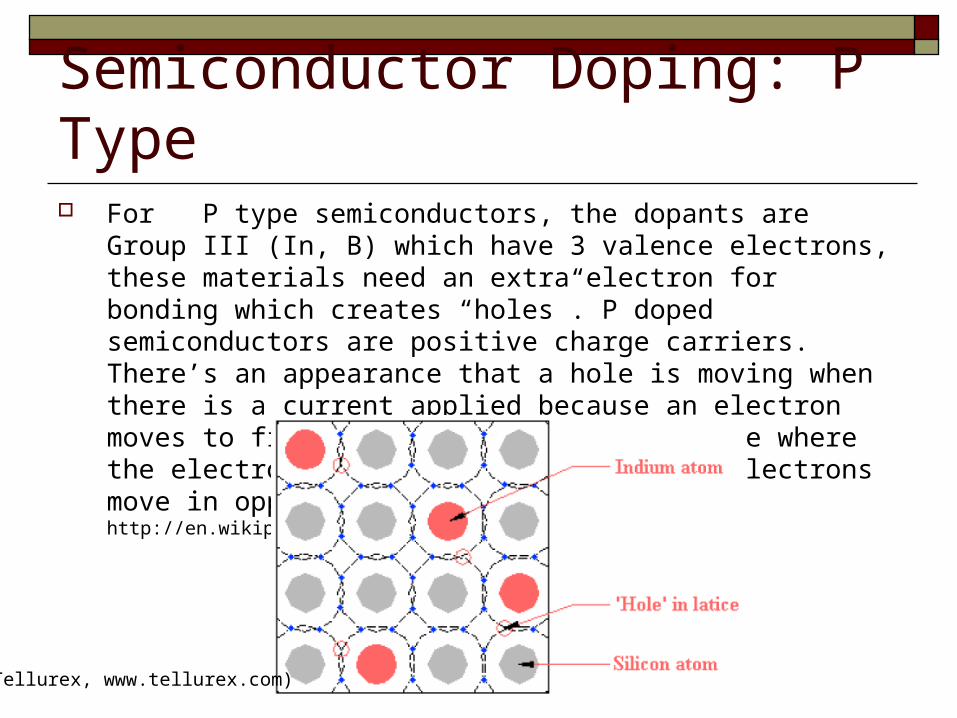
Semiconductor Doping: P Type For P type semiconductors, the dopants are Group III (In, B) which
have 3 valence electrons, these materials need an extra electron for bonding which creates “holes”. P doped semiconductors are positive charge carriers. There’s an appearance that a hole is moving when there is a current applied because an electron moves to fill a hole, creating a new hole where the electron was originally. Holes and electrons move in opposite directions. (Wikipedia, http://en.wikipedia.org/wiki/Semiconductor).
(Tellurex, www.tellurex.com)
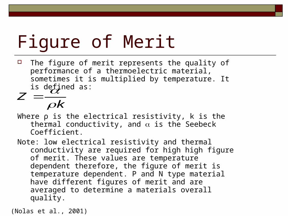
Figure of Merit The figure of merit represents the quality of performance of a
thermoelectric material, sometimes it is multiplied by temperature. It is defined as:
Where ρ is the electrical resistivity, k is the thermal conductivity, and is the Seebeck Coefficient.
Note: low electrical resistivity and thermal conductivity are required for high high figure of merit. These values are temperature dependent therefore, the figure of merit is temperature dependent. P and N type material have different figures of merit and are averaged to determine a materials overall quality.
kZ
(Nolas et al., 2001)
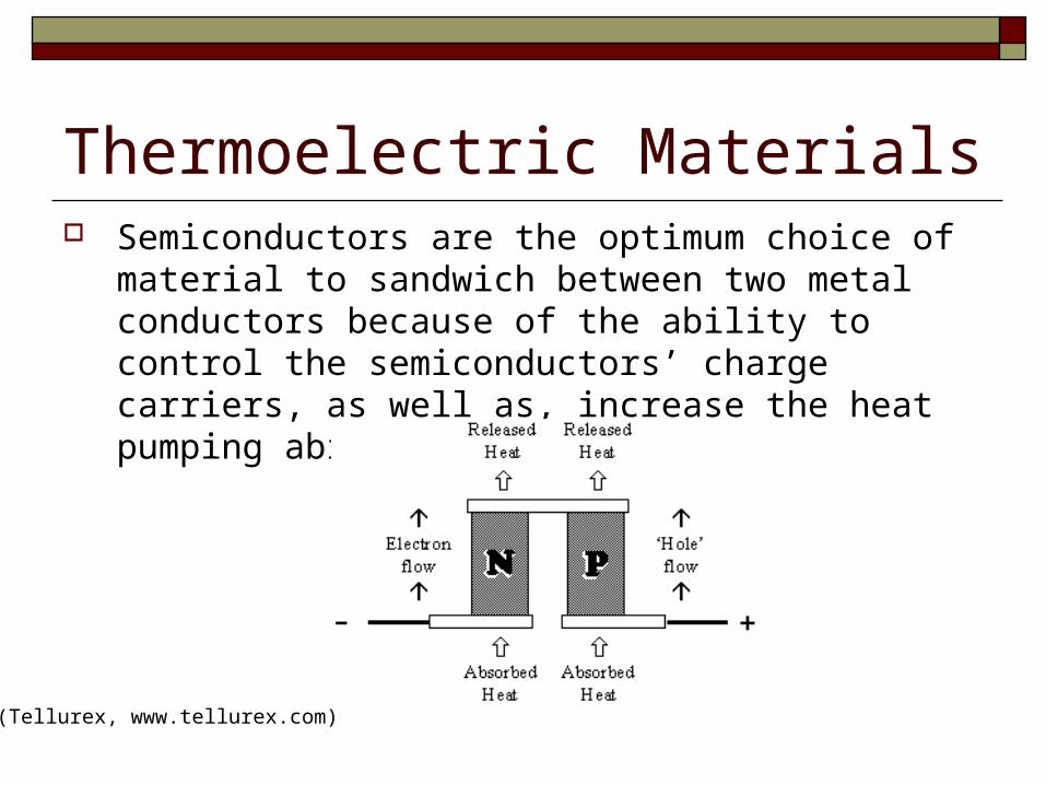
Thermoelectric Materials Semiconductors are the optimum choice of material to
sandwich between two metal conductors because of the ability to control the semiconductors’ charge carriers, as well as, increase the heat pumping ability.
(Tellurex, www.tellurex.com)
Thermoelectric Materials The most commonly used semiconductor for electronics
cooling applications is Bi2Te3 because of its relatively high figure of merit. However, the performance of this material is still relatively low and alternate materials are being investigated with possibly better performance.
Alternative materials include: Alternating thin film layers of Sb2Te3 and Bi2Te3. Lead telluride and its alloys SiGe Materials based on nanotechnology
(Sales, 2002)
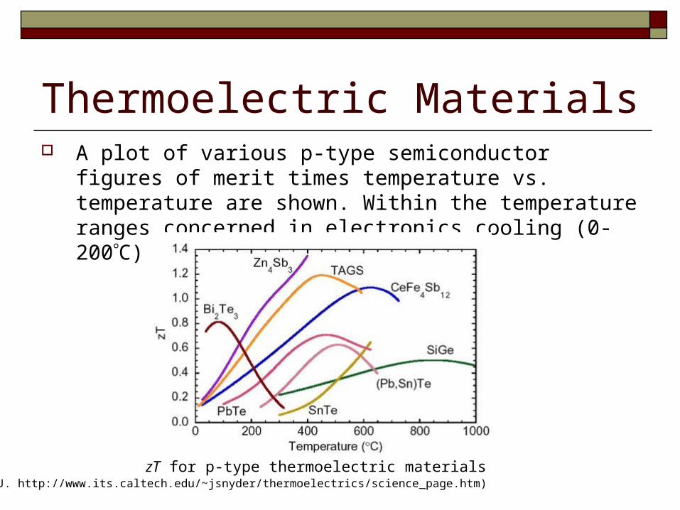
Thermoelectric Materials A plot of various p-type semiconductor figures of merit times
temperature vs. temperature are shown. Within the temperature ranges concerned in electronics cooling (0-200C) Bi2Te3 performs the best.
(Snyder, J. http://www.its.caltech.edu/~jsnyder/thermoelectrics/science_page.htm)zT for p-type thermoelectric materials
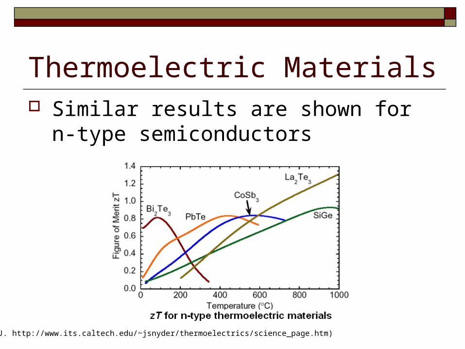
Thermoelectric Materials Similar results are shown for n-type
semiconductors
(Snyder, J. http://www.its.caltech.edu/~jsnyder/thermoelectrics/science_page.htm)
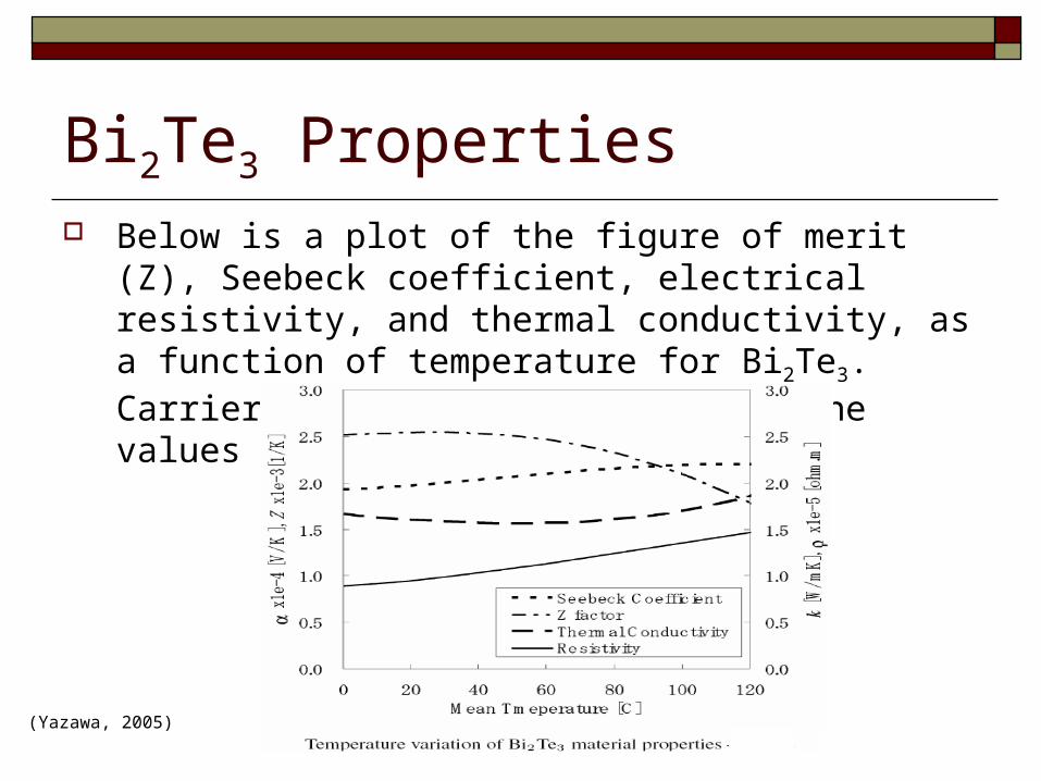
Bi2Te3 Properties Below is a plot of the figure of merit (Z), Seebeck coefficient,
electrical resistivity, and thermal conductivity, as a function of temperature for Bi2Te3. Carrier concentration will alter the values below.
(Yazawa, 2005)
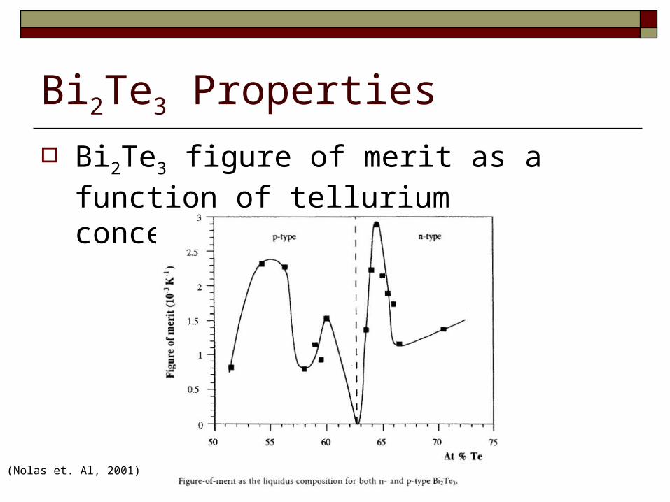
Bi2Te3 Properties
Bi2Te3 figure of merit as a function of tellurium concentration.
(Nolas et. Al, 2001)
Thermoelectric Materials Metals are used to sandwich the
semiconductor. Because the TE performance is also dependent on these materials, an optimal material must be chosen, usually copper.
Condensation A common problem with TE cooling is that condensation
may occur causing corrosion and eroding the TE’s inherent reliability.
Condensation occurs when the dew point is reached. The dew point is the temperature to which air must be cooled at constant pressure for the water vapor to start to condense
Condensation occurs because the air loses the ability to carry the water vapor that condenses. As the air’s temperature decreases its water vapor carrying capacity decreases.
Condensation Since TE coolers can cool to low and even below
ambient temperatures, condensation is a problem. The most common sealant employed is silicon
rubber (Nagy, 1997).
Research has been performed to determine the most effective sealing agent used to protect the chip from water.
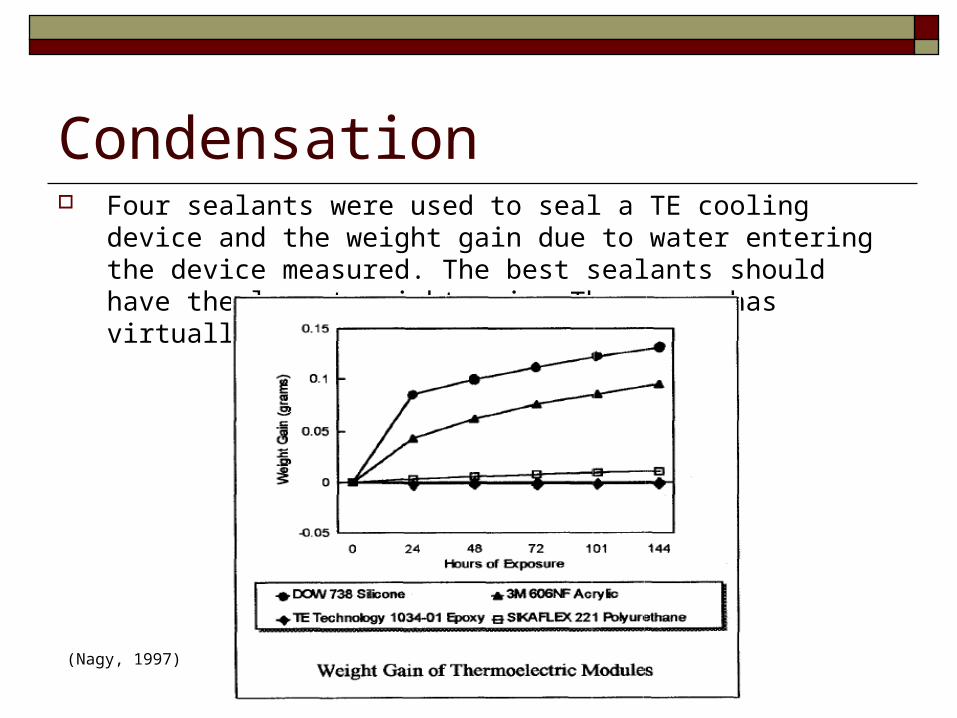
Condensation Four sealants were used to seal a TE cooling device and the weight gain
due to water entering the device measured. The best sealants should have the lowest weight gain. The epoxy has virtually no weight gain.
(Nagy, 1997)
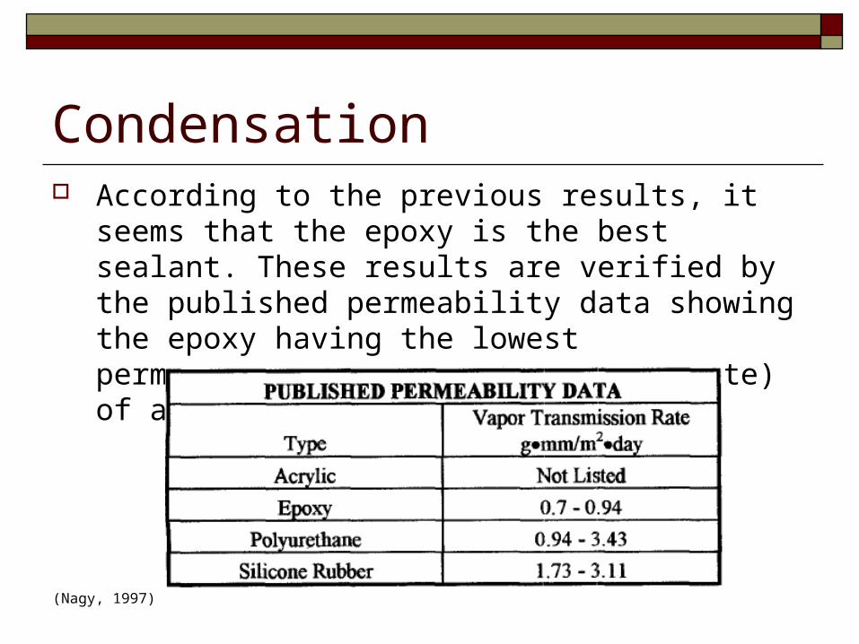
Condensation According to the previous results, it seems that the epoxy is
the best sealant. These results are verified by the published permeability data showing the epoxy having the lowest permeability (vapor transmission rate) of all the sealants.
(Nagy, 1997)
Thermoelectric Performance TE performance depends on the following factors:
The temperature of the cold and hot sides. Thermal and electrical conductivities of the device’s materials. Contact resistance between the TE device and heat source/heat sink. Thermal resistance of the heat sink.
(Chein and Huang, 1994)
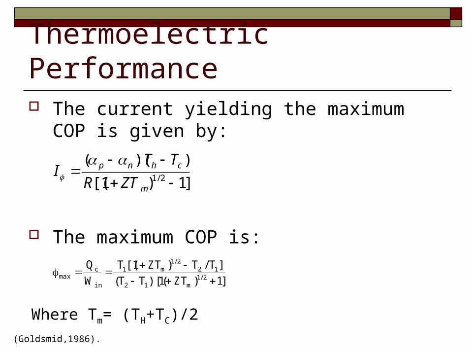
Thermoelectric Performance The current yielding the maximum COP is given
by:
The maximum COP is:
]1)1[(
))((2/1
m
chnp
ZTR
TTI
]1)ZT1)[(TT(
]T/T)ZT1[(T
W
Q2/1
m12
122/1
m1
in
cmax
(Goldsmid,1986).
Where Tm= (TH+TC)/2
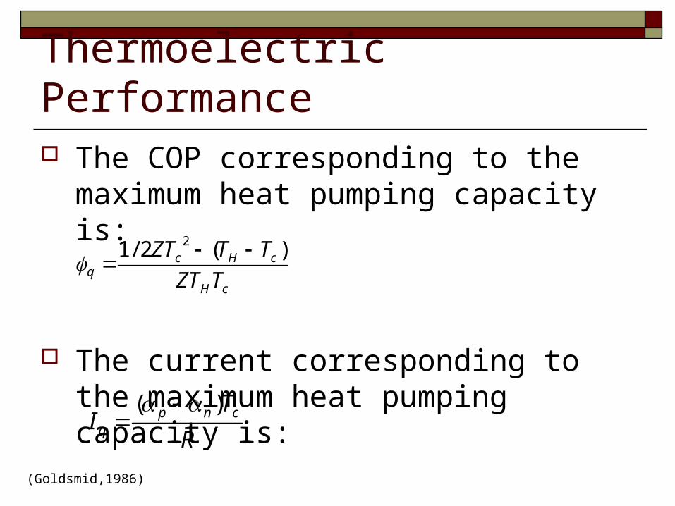
Thermoelectric Performance The COP corresponding to the maximum heat
pumping capacity is:
The current corresponding to the maximum heat pumping capacity is:
cH
cHcq TZT
TTZT )(2/1 2
R
TI cnp
q
)(
(Goldsmid,1986)
Coefficient of Performance A typical AC unit has a COP of
approximately 3. TE coolers usually have COP’s below 1; 0.4 to 0.7 is a typical range.
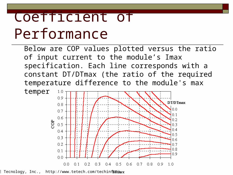
Coefficient of PerformanceBelow are COP values plotted versus the ratio of input current to the module’s Imax specification. Each line corresponds with a constant DT/DTmax (the ratio of the required temperature difference to the module's max temperature difference specification).
(TE Tecnology, Inc., http://www.tetech.com/techinfo/)
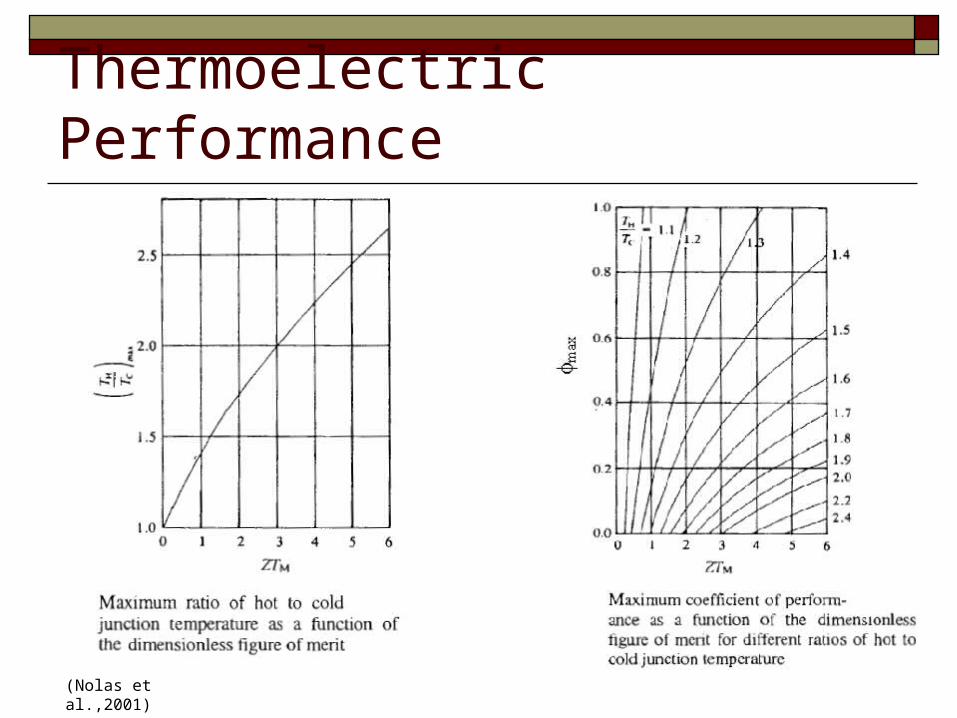
Thermoelectric Performance
(Nolas et al.,2001)
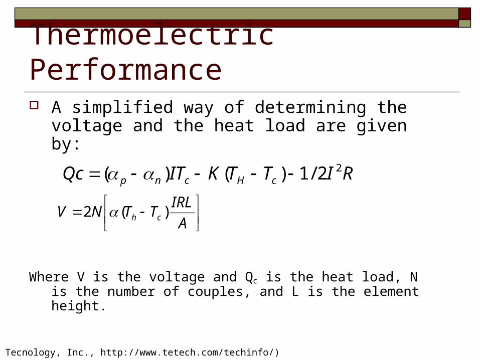
Thermoelectric Performance A simplified way of determining the voltage and
the heat load are given by:
Where V is the voltage and Qc is the heat load, N is the number of couples, and L is the element height.
A
IRLTTNV ch )(2
(TE Tecnology, Inc., http://www.tetech.com/techinfo/)
RITTKITQc cHcnp22/1)()(
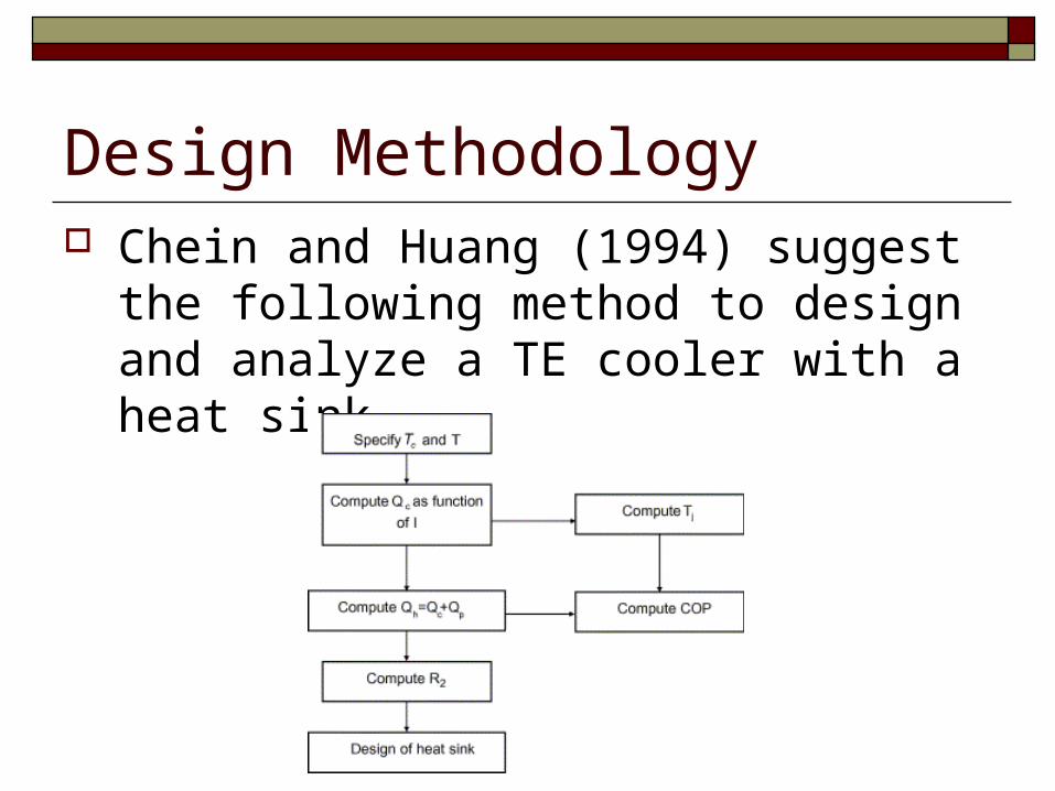
Design Methodology Chein and Huang (1994) suggest the
following method to design and analyze a TE cooler with a heat sink.
Design Methodology There are various ways to design a TE cooler. Each company
has a different methodology to design one that meets a given specification. Most companies have performance, current, temperature etc. data for their specific coolers which can be used for design. For example, the following websites by Tellurex (www.Tellurex.com) and Mollar (http://www.marlow.com/TechnicalInfo/themoelectric_cooler_selection_p.htm) have examples of their methodolgies. The next several sides displays Mollar’s design method. Note: or performance curve (or Figure 2) refers to the figure on the next slide.
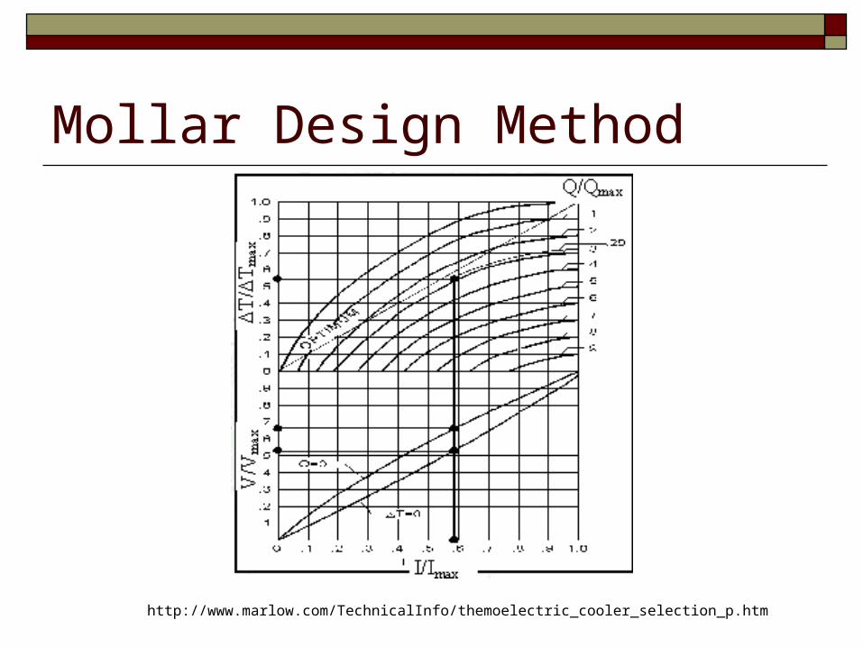
Mollar Design Method
http://www.marlow.com/TechnicalInfo/themoelectric_cooler_selection_p.htm
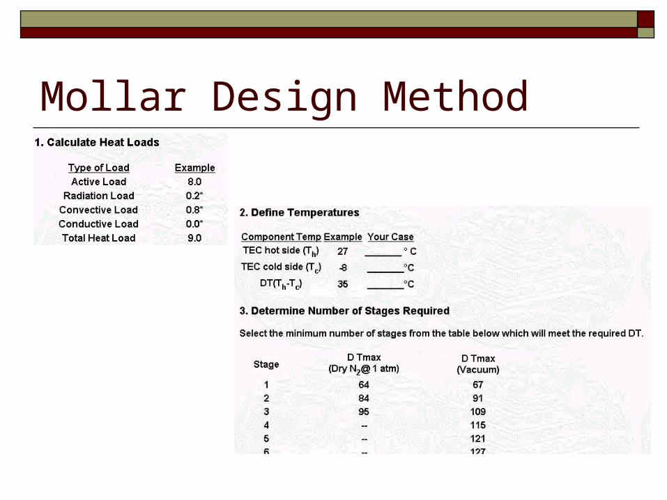
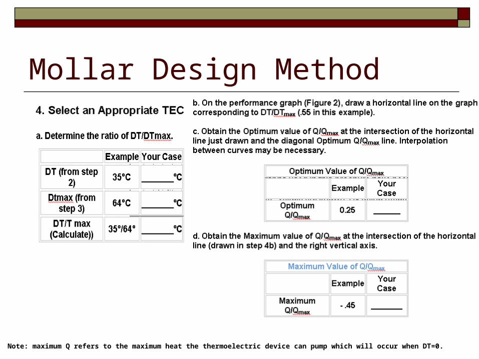
Mollar Design Method
Mollar Design Method
Note: maximum Q refers to the maximum heat the thermoelectric device can pump which will occur when DT=0.
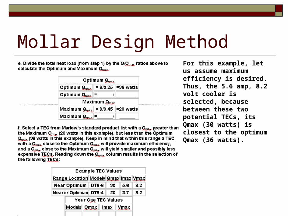
Mollar Design MethodFor this example, let us assume maximum efficiency is desired. Thus, the 5.6 amp, 8.2 volt cooler is selected, because between these two potential TECs, its Qmax (30 watts) is closest to the optimum Qmax (36 watts).
TE Technology, Inc. Some companies such as TE Technology, Inc. will offer
software (sometimes online applets) that allow the user to input certain design criteria and it will output the kind of TE cooler that will satisfy the criteria.
TE Technology, Inc’s. software (shown in the next couple of slides), allows the user to input the internal and external temperatures, as well as, the dimensions of the heat generating device and its heat production.
Among other things, the program will output the amount of power input to the TE cooler, its dimensions and the type of TE device that the company has available that will fulfill the design requirements.
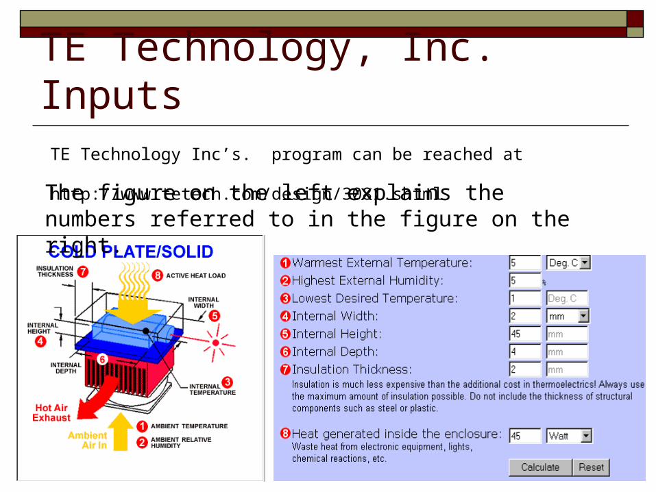
TE Technology, Inc. InputsTE Technology Inc’s. program can be reached at
http://www.tetech.com/design/3081.shtmlThe figure on the left explains the numbers referred to in the figure on the right.
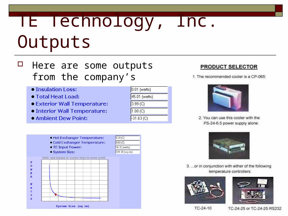
TE Technology, Inc. Outputs Here are some outputs from the
company’s program
Improving TE performance Various methods have been used to improve
the performance of TE coolers which are its major drawback.
Examples: thin film coolers or multistage (bulk) coolers.
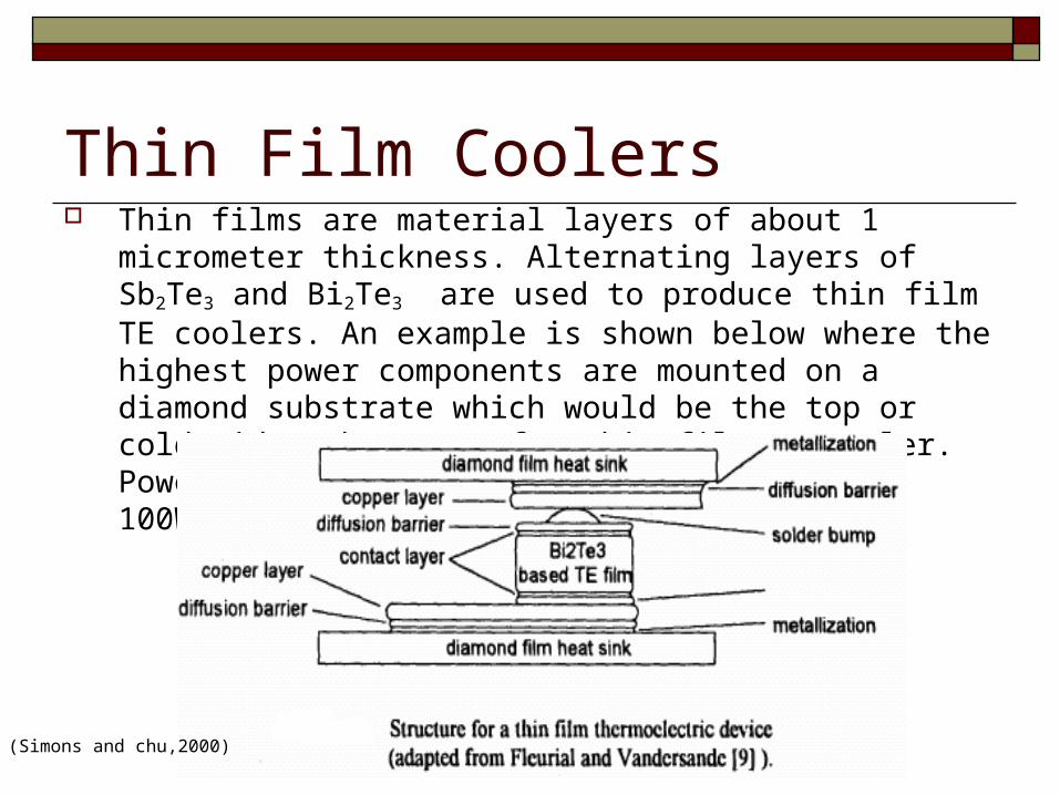
Thin Film Coolers Thin films are material layers of about 1 micrometer thickness.
Alternating layers of Sb2Te3 and Bi2Te3 are used to produce thin film TE coolers. An example is shown below where the highest power components are mounted on a diamond substrate which would be the top or cold side substrate of a thin film TE cooler. Power densities were reported to be above 100W/cm2.
(Simons and chu,2000)
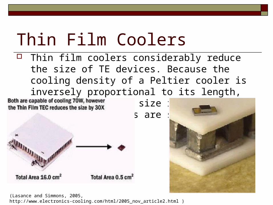
Thin Film Coolers Thin film coolers considerably reduce the size of TE
devices. Because the cooling density of a Peltier cooler is inversely proportional to its length, scaling to smaller size is desirable. A comparison of sizes are shown below.
(Lasance and Simmons, 2005, http://www.electronics-cooling.com/html/2005_nov_article2.html )
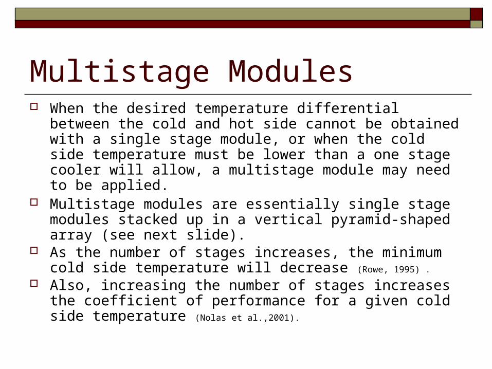
Multistage Modules When the desired temperature differential between the cold
and hot side cannot be obtained with a single stage module, or when the cold side temperature must be lower than a one stage cooler will allow, a multistage module may need to be applied.
Multistage modules are essentially single stage modules stacked up in a vertical pyramid-shaped array (see next slide).
As the number of stages increases, the minimum cold side temperature will decrease (Rowe, 1995) .
Also, increasing the number of stages increases the coefficient of performance for a given cold side temperature (Nolas et al.,2001).
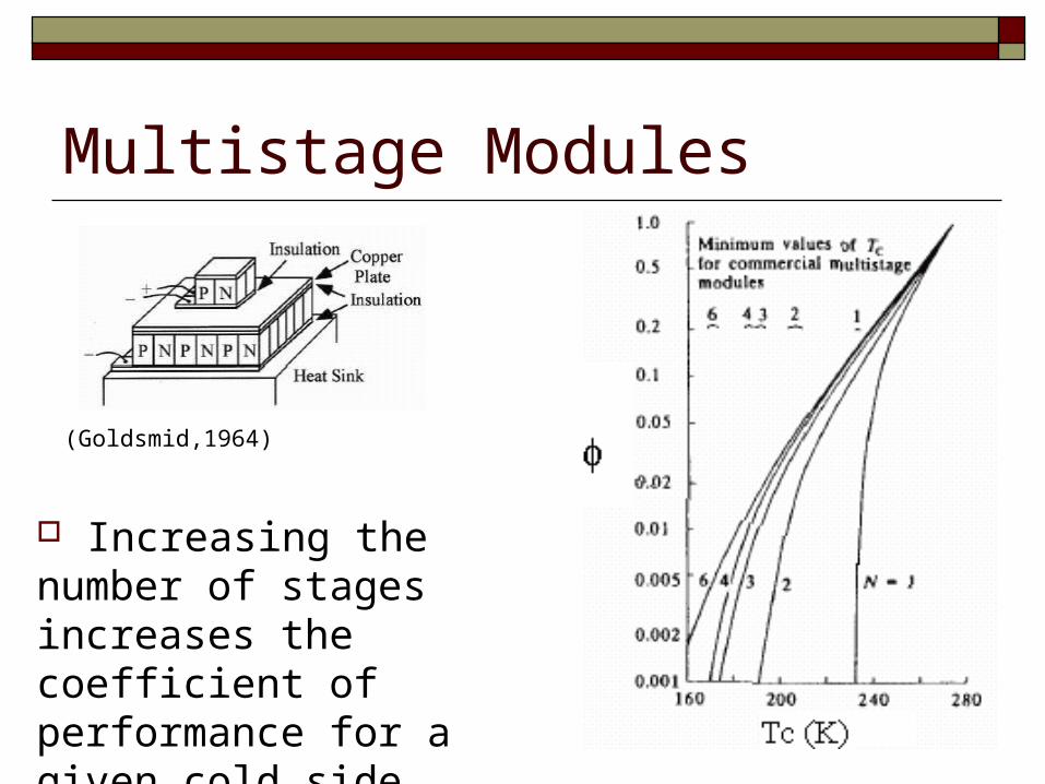
Multistage Modules
Increasing the number of stages increases the coefficient of performance for a given cold side temperature, as seen in the figure on the right (Goldsmid,1986).
(Goldsmid,1964)
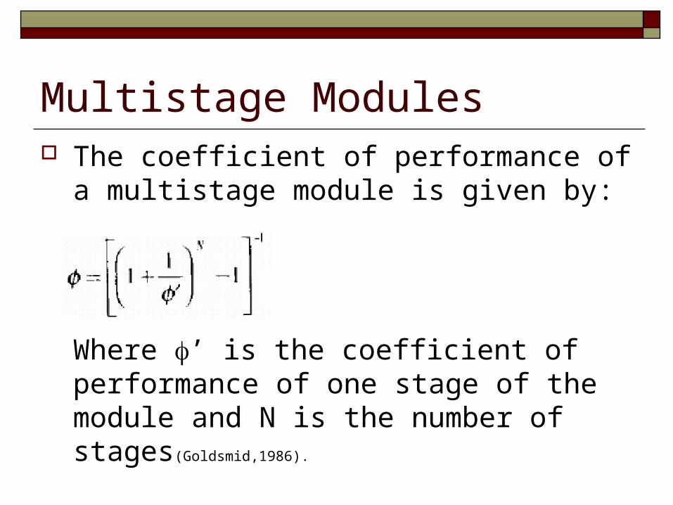
Multistage Modules The coefficient of performance of a
multistage module is given by:
Where ’ is the coefficient of performance of one stage of the module and N is the number of stages(Goldsmid,1986).
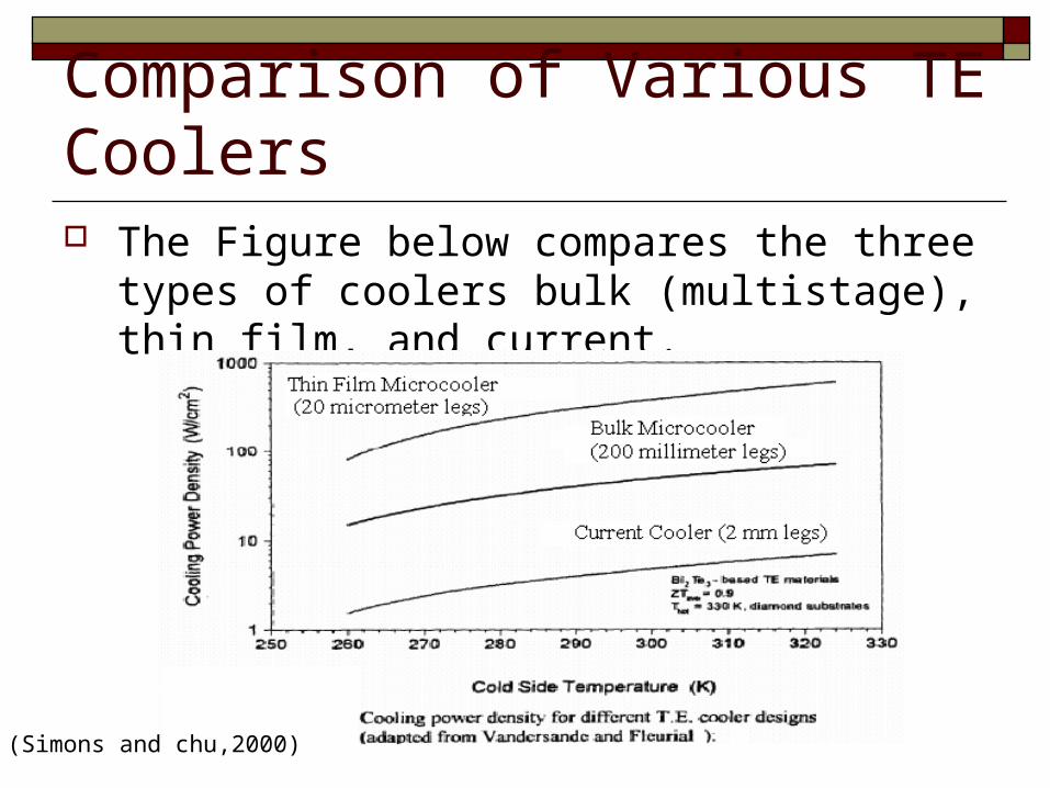
Comparison of Various TE Coolers The Figure below compares the three types of
coolers bulk (multistage), thin film, and current.
(Simons and chu,2000)
Improving Performance More exotic TE devices are being researched
that could result in better performance such as, superlattice structures, quantum wires and quantum wells, thin films using SiGe/Si, and thermionic cooling. However, research in these are preliminary and are not in widespread use.
Temperature stability TE cooling provides high degrees of temperature
stability because the amount of cooling it provides is proportional to the applied current.
The reported temperature stability of a TE device has been ±.0003 degrees celcius but considerable effort had to be used for this level of stability.
Several factors are involved in the temperature stability: The controller and its resolution. The response time of the specific cooling assembly The response time of the object being cooled.
(TE Tecnology, Inc., http://www.tetech.com/techinfo/)
TE Cooling of Electronics TE cooling devices are favorable in electronics cooling
systems because of their high reliability, flexibility in packaging and integration, low weight and ability to maintain a low junction temperature, even below ambient temperature.
Also, other cooling devices that can fit the tiny spaces required for electronics cooling, such as, a capillary loop heat or a miniature scale vapor compression refrigerator are not commercially available.
Disadvantages of these devices are the limit to their cooling capacity limit and coefficient of performance which may be restrictive in the future when heat transfer demands become much larger.(Chein and Huang, 1994)
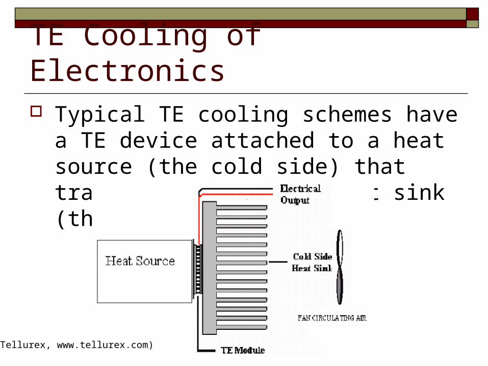
TE Cooling of Electronics Typical TE cooling schemes have a TE
device attached to a heat source (the cold side) that transports heat to a heat sink (the warm side).
(Tellurex, www.tellurex.com)
TE Cooling of Electronics Without a heat sink it is difficult to get an
adequate T but with a good airflow the heat sink size can be reduced.
A DC power supply is needed for the TE cooler.
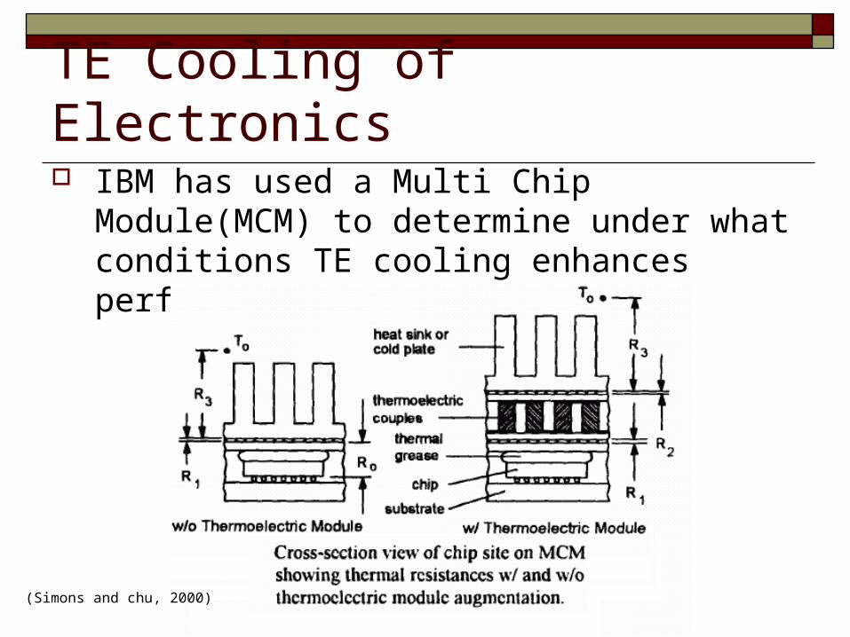
TE Cooling of Electronics IBM has used a Multi Chip Module(MCM) to
determine under what conditions TE cooling enhances performance.
(Simons and chu, 2000)
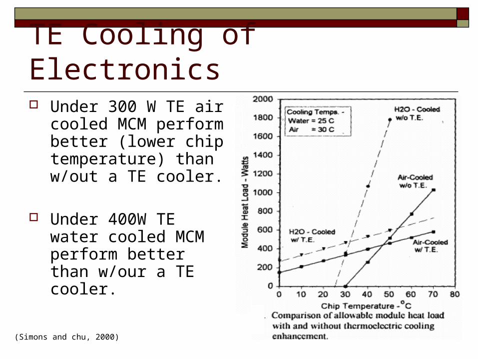
TE Cooling of Electronics Under 300 W TE air
cooled MCM perform better (lower chip temperature) than w/out a TE cooler.
Under 400W TE water cooled MCM perform better than w/our a TE cooler.
(Simons and chu, 2000)
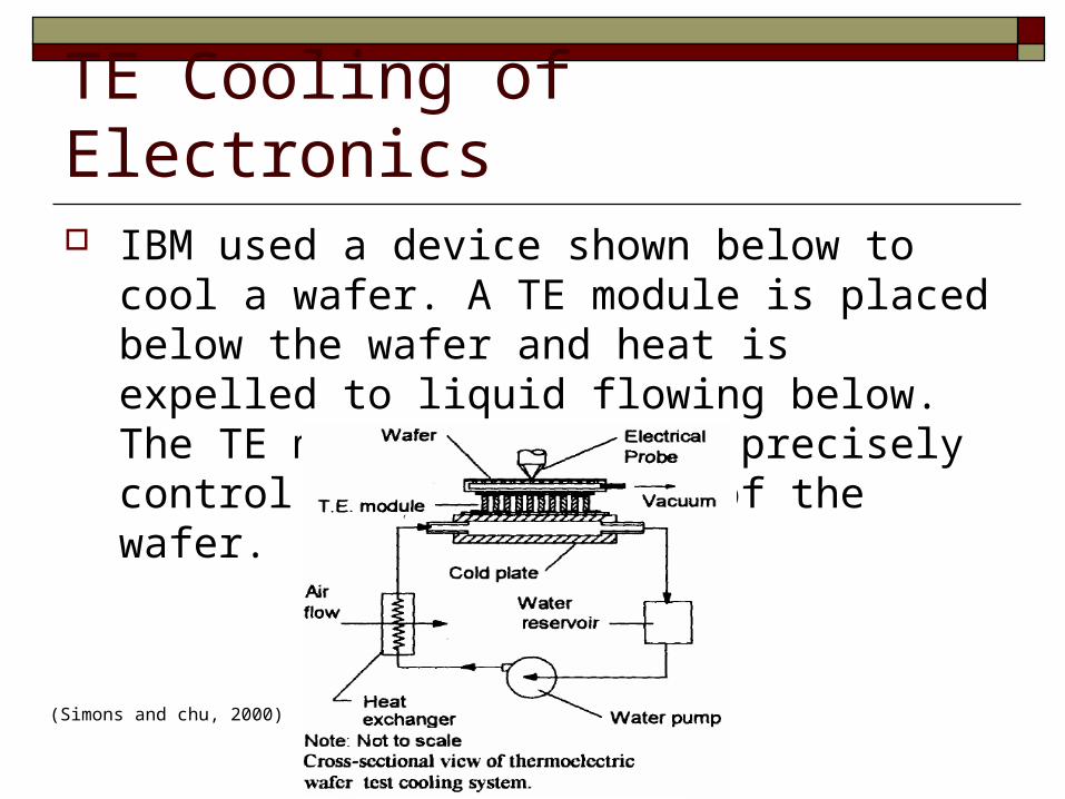
TE Cooling of Electronics IBM used a device shown below to cool a wafer. A
TE module is placed below the wafer and heat is expelled to liquid flowing below. The TE module is able to precisely control the temperature of the wafer.
(Simons and chu, 2000)
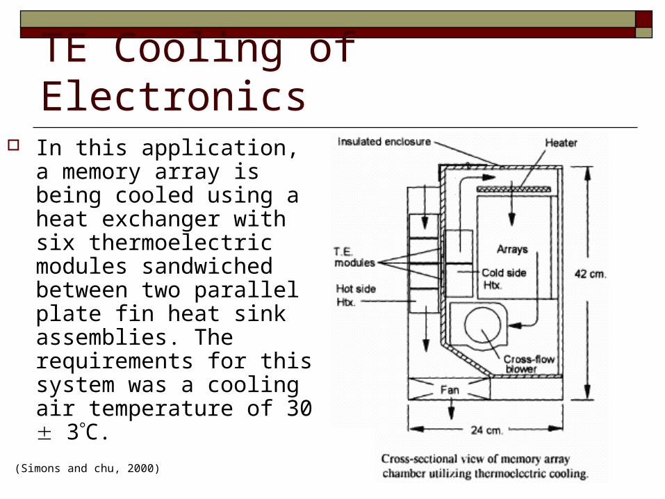
TE Cooling of Electronics In this application, a
memory array is being cooled using a heat exchanger with six thermoelectric modules sandwiched between two parallel plate fin heat sink assemblies. The requirements for this system was a cooling air temperature of 30 3C.
(Simons and chu, 2000)
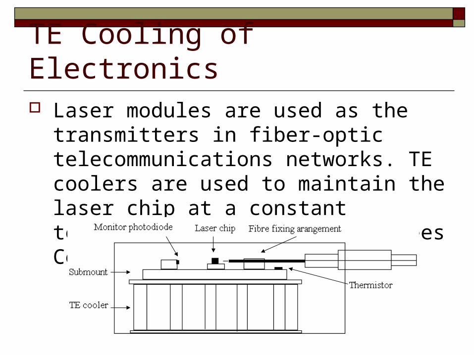
TE Cooling of Electronics Laser modules are used as the transmitters in
fiber-optic telecommunications networks. TE coolers are used to maintain the laser chip at a constant temperature typically, 25degrees Celsius (Rowe,1995).
Alternative Method of TE Cooling The heat produced by a computer chip can be used
to provide the electricity to run a fan that cools the chip. The fan uses a TE device operating on the Seebeck Effect to convert the heat to electricity.
When a laptop is running on batteries, the electricity used to power the fan comes from the battery. Therefore, to conserve battery life, a thermoelectric power generator is a good alternative.
(Bar-Cohen et al., 2005)
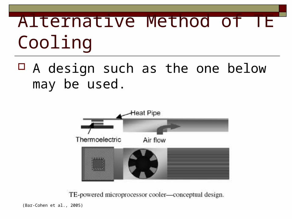
Alternative Method of TE Cooling A design such as the one below may be used.
(Bar-Cohen et al., 2005)
References Bar-Cohen, A., Solbrekken G. L., and Yazawa, K. (2005). Thermoelectric Powered Convective Cooling of Microprocessors. IEEE Transactions
of Advanced Packaging, 28(2). Chein, R. and Huang, G. (2004). Thermoelectric cooler application in electronic cooling. Applied Thermal Engineering, 24 (14-15), pp. 2207-
2217. Goldsmid H. (1986). Electronic Refrigeration.London:Pion. Goldsmid H.(1964). Thermoelectric Refrigeration. New York:Plenum. Lasance, C.J.M., and Simmons, R.E. (2005) Advances In High-Performance Cooling For Electronics. Electronics Cooling. Retrieved May2006.
http://www.electronics-cooling.com/html/2005_nov_article2.html Mollar(2003). Themoelectric Cooler Selection Procedure. Retieved June 2006.
http://www.marlow.com/TechnicalInfo/themoelectric_cooler_selection_p.htm Nagy, J. (1997). The Effectiveness of Water Vapor Sealing Agents When Used in Application With Thermoelectric Cooling Modules. 16th
International Conference on Thermoelectrics. Nolas, G.S. Goldsmid H., and Sharp J. (2001). Thermoelectrics : basic principles and new materials developments. New York: Springer. Rowe, D.M. (1995). CRC Handbook of Thermoelectrics. Boca Raton, FL: CRC Press. Sales, Brian. (February 2002). Thermoelectric Materials: Smaller is Cooler.. Science (Vol. 295. no. 5558, pp. 1248 – 1249). Retrieved April
2006. http://www.sciencemag.org/cgi/content/full/295/5558/1248 . Simons, R. E. and Chu, R. C. (2000) Application of thermoelectric cooling to electronic equipment: A review and analysis. Annual IEEE
Semiconductor Thermal Measurement and Management Symposium, pp1-9. Snyder, J. The Science and Materials behind Thermoelectrics. Caltech-JPL Thermoelectrics Website. Retrieved April 2006. Tellurex. (2002). Retrieved May 2006. http://www.tellurex.com Tellurex. (2002). The 12 Most Frequently Asked Questions About Themoelectric Cooling. Retrieved May 2006.
http://www.tellurex.com/12most.html TE Technology, Inc. (2005) Cold Plate/Solid. Free Design Service. Retrieved June 2006. http://www.tetech.com/design/3081.shtml TE Technology, Inc. Retrieved May 2006. http://www.tetech.com/techinfo/ TE Technology, Inc. (2005). Thermoelectric Modules. Retrieved April 2006. http://www.tetech.com/modules/ Wikipedia the Free Encyclopedia(May 2006). Semiconductor.. Retrieved May 2006. http://en.wikipedia.org/wiki/Semiconductor. Wikipedia the Free Encyclopedia (May 2006). Condensation. Retrieved May 2006. http://en.wikipedia.org/wiki/Condensation