Embed Size (px)
Citation preview

Powering Mesh Networks for Environmental Sensing in Remote Areas
Department of Electrical and Computer Engineering Graduate Studies
Doug Frome
2 April 2013

Introduction - MESA Project
– Mountainous Ecosystem Sensor Array
• Three dimensional monitoring of the ecosystem
• 78 sensors total – 26 per site – 3 sites (Micro-Nets)
• Located in the Frank Church Wilderness of No Return in the State of Idaho

MESA project Goals • To achieve real time wireless three dimensional monitoring of
a mountainous ecosystem.
• To make the system autonomous such that maintenance of the system is only required once per year.
• To physically install the system and have it functioning within one year.
• To have all sensors tested for precision and be within 10% tolerance of all other like sensors.
• To receive all data generated by all of the sensors with minimal interruptions.
• To develop a system to manage and store the data generated by the sensors in the project.
• To comply with all the minimum impact requirements in the Wilderness Act of 1964.

Mid site Upper site
Lower site

½ crown height
5
Sensor Sensor
#
CO2 (2 min) 1
Air T/RH (2 min) 2
soil h20/T (30 min) 3
WXT520 4
Net Radiation (2 min) 5
Snow Depth (2 hr) 6
Dendrometer (1 hr) 8
Leaf Wetness (2 min) 9
4
9 5
8
5
9 2 1
4
9 1
2m
½ crown radius
½ crown radius
Full crown radius
123W
Camo Solar Panel in Tree
Wind Turbine
Main Tree Sensor Locations
Aluminum Pipe
1

10W 10W 10W
8 8
6 6 6
3m 3m
3
3
3
3
3
3
3
3 ½ crown radius
Sensor Sensor
#
CO2 (2 min) 1
Air T/RH (2 min) 2
soil h20/T (30 min) 3
WXT520 4
Net Radiation (2 min) 5
Snow Depth (2 hr) 6
Dendrometer (1 hr) 8
Leaf Wetness (2 min) 9
Tree #1 Tree #2 Dead Snag
Tree #3
Solar Panel in Tree
Aluminum Pipe
50cm 50cm

Standards for mounting Equipment
• Can not harm the trees
• Has to have low visibility
• Animal proof
• Must be transportable by:
–human, mule, car, and small plane

Top Assembly – Main Tree
• Assembled in lowered position, then raised.
• Extension beam
gets equipment out of branches.
• As simple as this looks; it took a long time to get the design right.

Fastening the Main Mast • Mast pipe is secured by
two sets of tree braces with crosspieces.
• Crosspiece U-bolts hold mast pipe.

View of Tree braces, crosspiece, and mast pipes

Solar Panel in Main Tree • Meets min. impact • Camouflage • Black pipe • Low Visibility

• Tangential Tree Mount (Left)
• Radial Tree Mount (Below)
• Tree Braces • Ratchet Straps • Strut (Bolted) • Pipe Clamps • Anodized pipe and powder
coated strut (Low Visibility) Meets min. Impact Req.

Tertiary Tree – Snow Depth Sensor & Solar Panel
Nu-Rail allows two axis rotation for positioning of snow depth sensors parallel with the ground. Solar panel also has two directions of rotation.
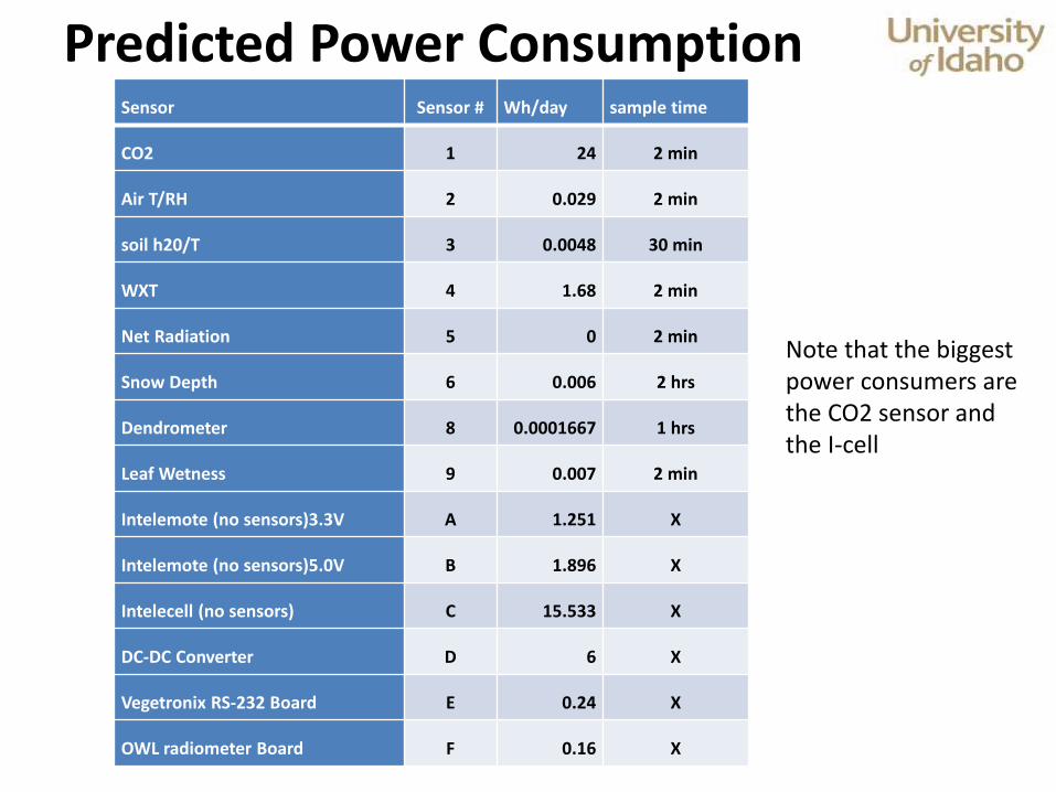
Sensor Sensor # Wh/day sample time
CO2 1 24 2 min
Air T/RH 2 0.029 2 min
soil h20/T 3 0.0048 30 min
WXT 4 1.68 2 min
Net Radiation 5 0 2 min
Snow Depth 6 0.006 2 hrs
Dendrometer 8 0.0001667 1 hrs
Leaf Wetness 9 0.007 2 min
Intelemote (no sensors)3.3V A 1.251 X
Intelemote (no sensors)5.0V B 1.896 X
Intelecell (no sensors) C 15.533 X
DC-DC Converter D 6 X
Vegetronix RS-232 Board E 0.24 X
OWL radiometer Board F 0.16 X
Predicted Power Consumption
Note that the biggest power consumers are the CO2 sensor and the I-cell

Main Tree Sensor #s Wh/year Wh/day # motes
Top 1,4,5,9,C,F 15103.7 41.38 1 cell
Mid Canopy 1,2,9,B,D 11655.18 31.932 1 mote
Base of Canopy 5,9,B,D 2884.595 7.903 1 mote
Base of Tree 1,4,5,8,B,B,B,D,D,D 18019.38085 49.3681667 3 motes
Main Tree Total: 47662.85585 130.5831667
Other Trees Sensor #s Wh/year Wh/day # motes
Tree 1 3,3,3,3,6,6,8,A,A,E 1012.278846 2.7733667 2 motes
Tree 2 3,3,3,3,6,A,E 553.413 1.5162 1 mote
Tree 3 8,A 456.6758455 1.2511667 1 mote
Predicted Power Consumption Per Power System

Wh/day Ah/day @12V W continious I continuous Wh/5days Ah/5days @ 12V
Main Tree 130.5832 10.88193056 5.440965279 0.453413773 652.915834 54.40965279
Wh/day Ah/day @3.3V W continuous I continuous Wh/5days Ah/5days @ 3.3V
Tree 1 2.773367 0.840414152 0.115556946 0.035017256 13.8668335 4.202070758
Tree 2 1.5162 0.459454545 0.063175 0.019143939 7.581 2.297272727
Tree 3 1.251167 0.379141424 0.052131946 0.015797559 6.2558335 1.895707121
Predicted Power and Current
Measured Power and current Wh/day Ah/day @12V W continious I continuous Wh/5days Ah/5days @ 12V
Main Tree 113.9328 9.4944 4.7472 0.3956 569.664 47.472
Wh/day Ah/day @3.3V W continuous I continuous Wh/5days Ah/5days @ 3.3V
Tree 1 2.66904 0.8088 0.11121 0.0337 13.3452 4.044
Tree 2 1.80576 0.5472 0.07524 0.0228 9.0288 2.736
Tree 3 1.09296 0.3312 0.04554 0.0138 5.4648 1.656
Measured Ah/5days values are used for battery bank sizing

Ah/5days @ 12V Battery Bank Size Ah
Main Tree 47.472 118.68
Ah/5days @ 3.3V Battery Bank Size Ah
Tree 1 4.044 10.11
Tree 2 2.736 6.84
Tree 3 1.656 4.14
Battery Bank Size = [Amp Hours Needed for 5 days/60%]*1.5
Values in the first column were taken from the table on the previous slide.

Batteries – Lead acid
• Sealed AGM used – does not leak acid during transport
• No need to refill fluids, no maintenance
– Lithium-ion
• Lithium iron phosphate (LiFePO4) used because of superior fire safety
• Other types of Lithium-ion batteries are pyrophoric
– Nickel
• cadmium, nickel-metal hydride
• Not used because of temperature and memory effects

Battery Configurations
• Main Tree
– Deka AGM
– 3 parallel 55Ah 12V batteries
– 165Ah total (main bus)
• Peripheral trees
– A123-26650 LiFePO4
– 4 parallel 2.5Ah 3.3V
– 10Ah total (per tree)
Battery Bank Size Ah
Main Tree = 118.68
Tree 1 = 10.11
Tree 2 = 6.84
Tree 3 = 4.14
Minimum Calculated Bank Size:

Main Tree Power System
Diode blocks reverse current flow into solar panels at night.
Main bus and Forgen wires are in 12-4 SJOW cable
Tertiary trees have similar power system, but no wind turbine.

Wire
gauge
ohms
@ 75ft
ohms
@ 100ft
V drop @ 75ft
@400mA
V drop @ 100ft
@ 400mA
P loss (Watts)
@ 75ft
P loss (Watts)
@ 100ft
10 0.0749175 0.09989 0.029967 0.039956 0.0119868 0.0159824
12 0.1191 0.1588 0.04764 0.06352 0.019056 0.025408
14 0.189375 0.2525 0.07575 0.101 0.0303 0.0404
22 1.2105 1.614 0.4842 0.6456 0.19368 0.25824
24 1.92525 2.567 0.7701 1.0268 0.30804 0.41072
Main Bus Voltage Drop Considerations: • 12 gauge wire was chosen • Less than a tenth of a volt drop across a 100 foot bus • 25mW of power consumption • Bus Current = 9.4944Ah/24h ≈ 400mA (Based off of measured current)

Solar Considerations:
• The Solar panel does not produce sufficient power when light is below a certain thresh-hold.
• Can not harvest all of the light in a day; low levels of radiance are not usable.
STAR 123 Warner Energy Panel • Vmpp = 20.95V • Impp = 5.93A • Nominal Power = 123W
1.9A @ 300W/m^2

Radiance (Mid Site) 12/2/12 – 12/6/12
0
100
200
300
400
500
600
700
6:00 7:12 8:24 9:36 10:48 12:00 13:12 14:24 15:36 16:48
12/6/2012
12/5/2012
12/4/2012
12/3/2012
12/2/2012
• Assume 12/3/2012 is a sunny day in December at MESA Mid Site with 2.5 hours of radiance above 300W/m^2
• Estimate 1.5 sunny December days out of every 5 days = bad weather
• This results in (1.5days)*(2.5hr/day) ≈ 3.75hr/5days of radiance greater than 300W/m^2
W/m
^2
Time of Day


Horizon H-series: days of operation @ full power
Norco Cylinder
Size
Volume (Liters)
@ 0.5atm
Days of Operation
H-12 (12 Watts)
Days of Operation
H-20 (20 Watts)
Days of Operation
H-30 (30 Watts)
Q 4528 17.47 11.23 7.48
S 8490 32.75 21.05 14.03
K 12452 48.04 30.88 20.59
• The Main Tree power consumption is 4.75W continuous.
• The “K” cylinder would power the main tree for 121.36 days if
the H-12 fuel cell was used.
• (12W/4.75W)*48.04days = 121.36days

Equipment

Definition of a Mesh Network
• The definition of a mesh network is a Local Area Network (LAN) where each node can operate as an independent router.
• This means that if one of the routers is removed, then the others readjust and re-route the network transmissions.
• For the MESA project, these nodes are referred to as “motes” or “i-cells”.

Mesh Networks in the MESA system
mote
mote
mote mote
mote
• Mote mesh system uses the Xbee-Pro® Radio and Digi-mesh algorithm.
• I-cell mesh system uses the Zigbee X-Tend® radio and a mesh algorithm developed by Intelesense.
• Each I-cell has a Xbee-Pro® Radio to mesh with motes.

XBee-PRO® 900/DigiMesh™ 900 OEM RF Modules
• 900MHz Radio • Proprietary Driver • Indoor/Urban: up to
450ft (140m) • Outdoor line-of-sight: up
to 1.8 miles (3 km) • Transmit Power Output:
50 mW (+17dBm) • Receiver Sensitivity: -100
dBm • RF Data Rate: 156.25
kbps

The main features of the Digi-mesh protocol are:
• The network is self healing.
• Peer-to-peer architecture.
• Route Discovery
• Selective Acknowledgements: –Only the destination mote will reply
to a route request
• Sleep modes

Sensor Interface – Radiometer & Soil

Radiometer Data Path
Radiometer OWL
(OP Amps)
Spark Fun RS232
converter
Intelecell
Low Voltage Signals
3V RS232
12V RS232

Intelecell
Soil Sensor Data Path
Veggie Tronix
SDI Bus
RS232 Bus
Soil
Sen
sors

LEM schematic – Power Monitoring

Questions ???