Embed Size (px)
Citation preview
3
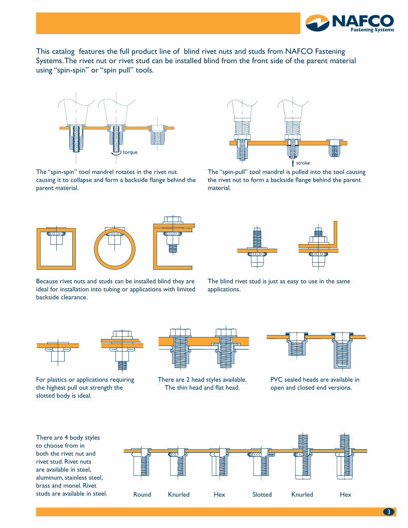
This catalog features the full product line of blind rivet nuts and studs from NAFCO Fastening Systems. The rivet nut or rivet stud can be installed blind from the front side of the parent material using “spin-spin” or “spin pull” tools.
The “spin-spin” tool mandrel rotates in the rivet nut causing it to collapse and form a backside flange behind the parent material.
The “spin-pull” tool mandrel is pulled into the tool causing the rivet nut to form a backside flange behind the parent material.
Because rivet nuts and studs can be installed blind they are ideal for installation into tubing or applications with limited backside clearance.
The blind rivet stud is just as easy to use in the same applications.
Round Knurled Hex Slotted Knurled Hex
There are 4 body styles to choose from in both the rivet nut and rivet stud. Rivet nuts are available in steel, aluminum, stainless steel, brass and monel. Rivet studs are available in steel.
For plastics or applications requiring the highest pull out strength the slotted body is ideal.
PVC sealed heads are available in open and closed end versions.
There are 2 head styles available. The thin head and flat head.
stroke
torque
4
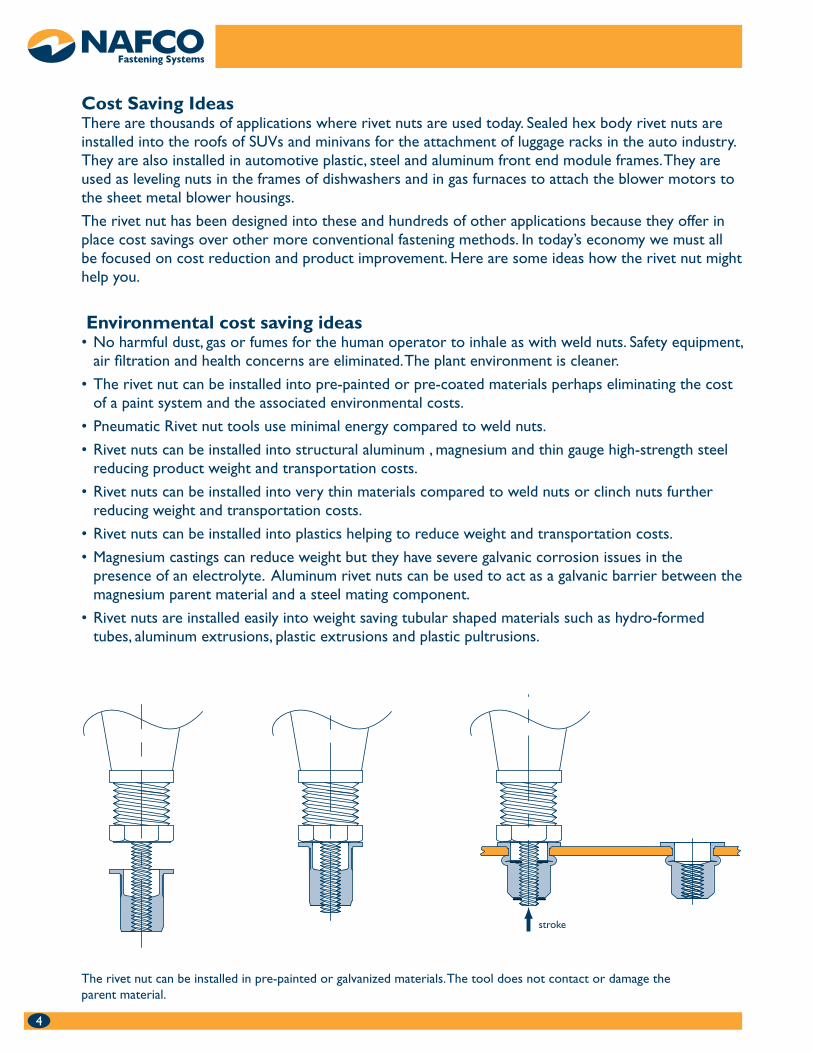
Environmental cost saving ideas No harmful dust, gas or fumes for the human operator to inhale as with weld nuts. Safety equipment, •air filtration and health concerns are eliminated. The plant environment is cleaner.
The rivet nut can be installed into pre-painted or pre-coated materials perhaps eliminating the cost •of a paint system and the associated environmental costs.
Pneumatic Rivet nut tools use minimal energy compared to weld nuts.•
Rivet nuts can be installed into structural aluminum , magnesium and thin gauge high-strength steel •reducing product weight and transportation costs.
Rivet nuts can be installed into very thin materials compared to weld nuts or clinch nuts further •reducing weight and transportation costs.
Rivet nuts can be installed into plastics helping to reduce weight and transportation costs.•
Magnesium castings can reduce weight but they have severe galvanic corrosion issues in the •presence of an electrolyte. Aluminum rivet nuts can be used to act as a galvanic barrier between the magnesium parent material and a steel mating component.
Rivet nuts are installed easily into weight saving tubular shaped materials such as hydro-formed •tubes, aluminum extrusions, plastic extrusions and plastic pultrusions.
Cost Saving IdeasThere are thousands of applications where rivet nuts are used today. Sealed hex body rivet nuts are installed into the roofs of SUVs and minivans for the attachment of luggage racks in the auto industry. They are also installed in automotive plastic, steel and aluminum front end module frames. They are used as leveling nuts in the frames of dishwashers and in gas furnaces to attach the blower motors to the sheet metal blower housings.
The rivet nut has been designed into these and hundreds of other applications because they offer in place cost savings over other more conventional fastening methods. In today’s economy we must all be focused on cost reduction and product improvement. Here are some ideas how the rivet nut might help you.
The rivet nut can be installed in pre-painted or galvanized materials. The tool does not contact or damage the parent material.
stroke
5
Rivet nut cost savings ideas Rivet nuts can be installed on a moving assembly line rather than in a separate remote location as •with weld nuts or clinch nuts. Material handling costs are reduced.
Rivet nut tools are significantly lower in cost than weld nut, pierce nut or clinch nut equipment. •
Why use a weld nut, pierce nut or clinch nut in an application where the attachment is an “option” •and not installed in every build. Make the hole and install the rivet nut or stud only if it is needed in final assembly after paint.
Weld nuts require the parent material to be thick enough to prevent burn through. The rivet nut can •be installed in thinner materials.
The heat from weld nuts cause warping of the parent material. There is no heat involved with the •rivet nut.
Weld flash in the threads of a weld nut calls for 100% thread gauging. The rivet nut tool acts as a •thread gauge when it installs the part.
Masking of threads in weld, pierce and clinch nuts is eliminated when the rivet nut is installed after •painting.
Rivet nuts have larger tolerance holes than clinch nuts. This reduces cost.•
Weld nuts require destructive testing to determine precise installation. Rivet nut tools can monitor •the installation process parameters of stroke and pressure eliminating the need for destructive testing. They can also count installations to be sure all rivet nuts were installed.
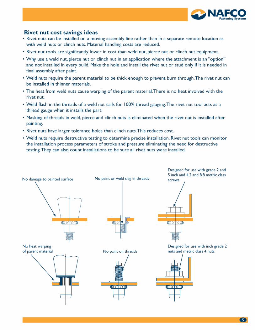
No paint or weld slag in threadsNo damage to painted surface
Designed for use with grade 2 and 5 inch and 4.2 and 8.8 metric class screws
No heat warpingof parent material No paint on threads
Designed for use with inch grade 2 nuts and metric class 4 nuts
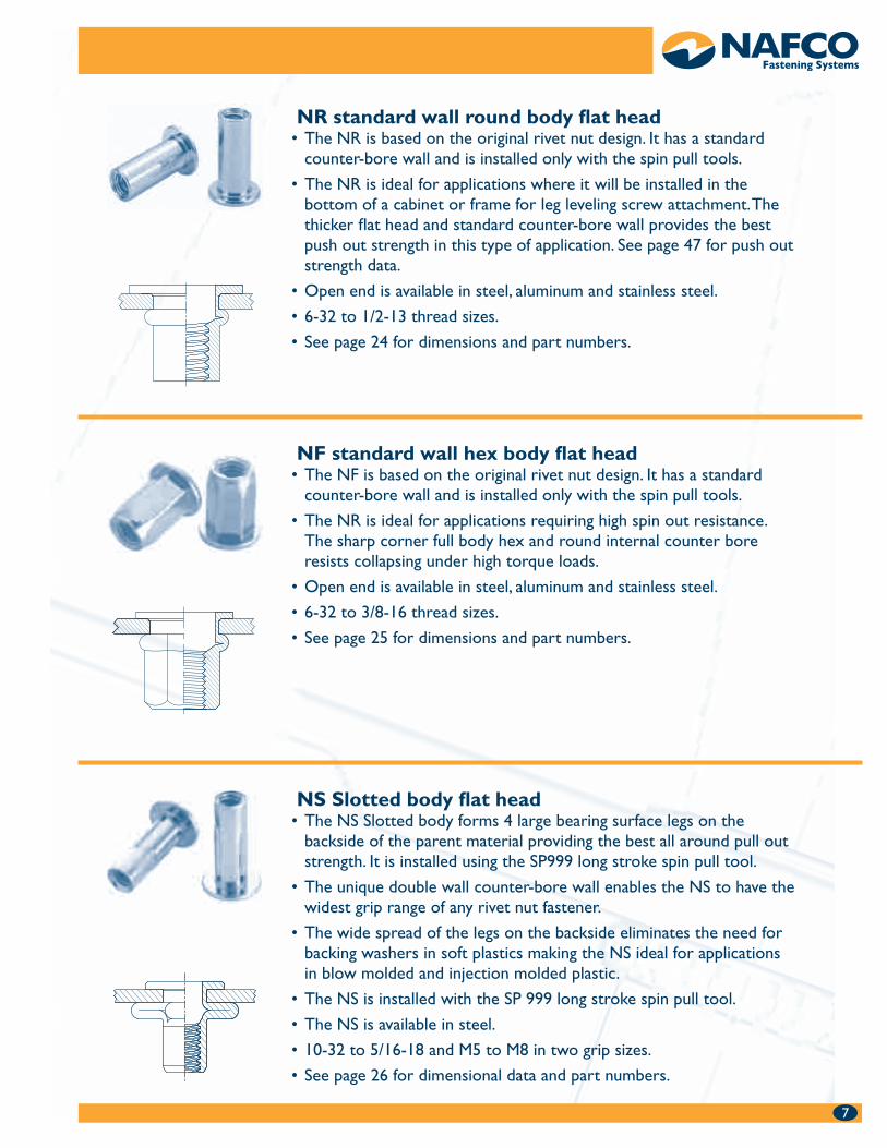
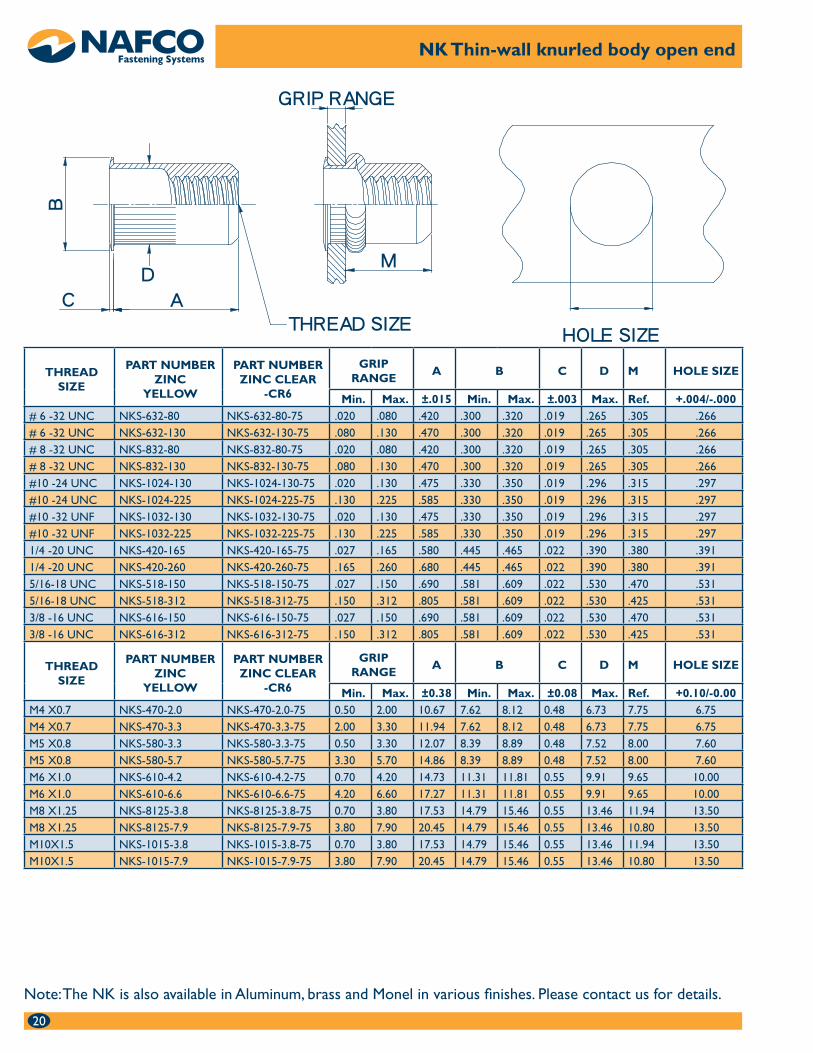
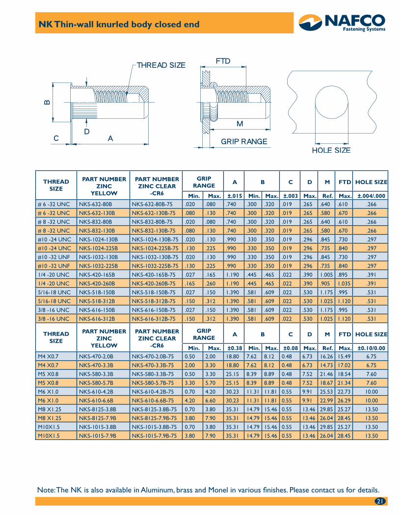
NK Thin wall knurled body thin head The thin wall counter-bore of the NK enables it to be installed into single, •variable or multiple thickness parent materials with the spin spin tool without adjustment for parent material thickness.
It can also be installed in single thickness parent materials with the spin •pull tools for ultimate installation speed.
The thin head allows the NK to be installed near flush with no special •hole preparation.
The knurled body provides increased spin out resistance.•
Available in open and closed end in steel, aluminum, brass and monel. •
6-32 to 3/8-16 and M4 to M10 thread sizes in various grip ranges.•
See page 20 and 21 for dimensional data and part numbers.•
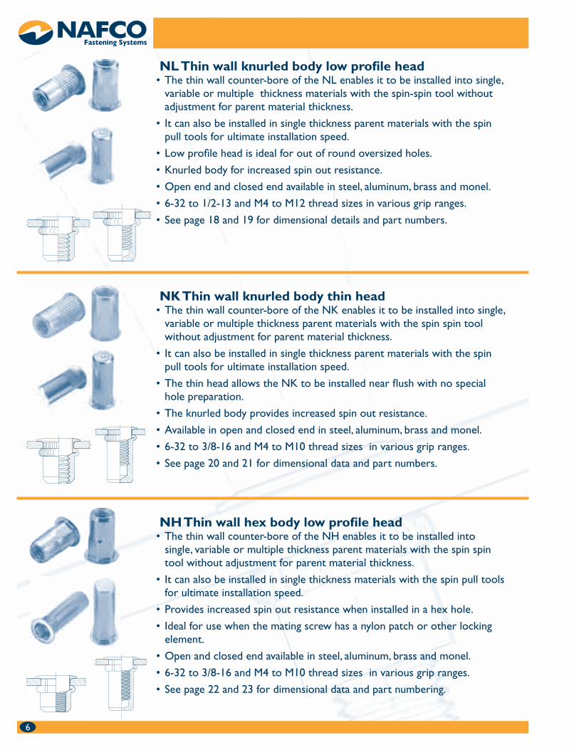
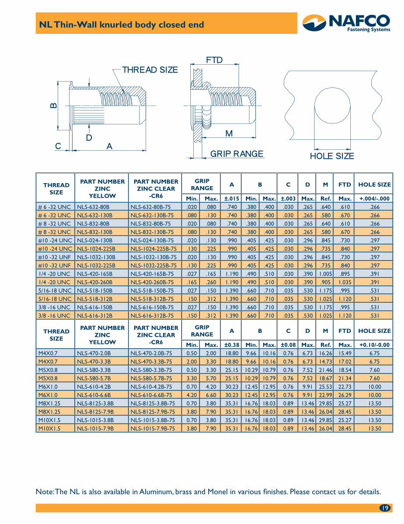
NL Thin wall knurled body low profile head The thin wall counter-bore of the NL enables it to be installed into single, •variable or multiple thickness materials with the spin-spin tool without adjustment for parent material thickness.
It can also be installed in single thickness parent materials with the spin •pull tools for ultimate installation speed.
Low profile head is ideal for out of round oversized holes.•
Knurled body for increased spin out resistance.•
Open end and closed end available in steel, aluminum, brass and monel.•
6-32 to 1/2-13 and M4 to M12 thread sizes in various grip ranges.•
See page 18 and 19 for dimensional details and part numbers.•
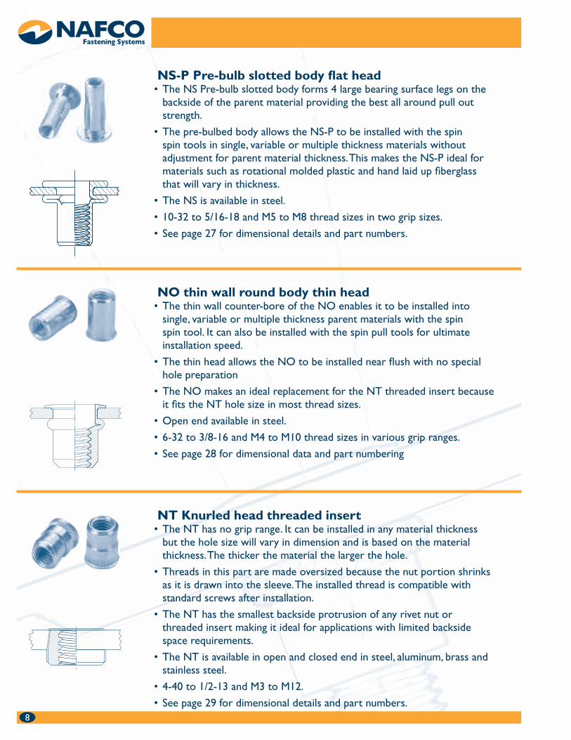
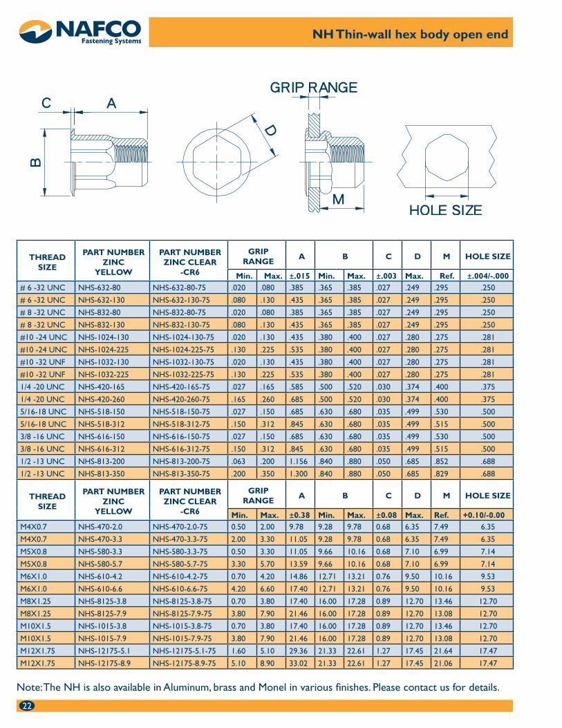
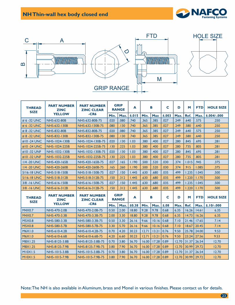
NH Thin wall hex body low profile head The thin wall counter-bore of the NH enables it to be installed into •single, variable or multiple thickness parent materials with the spin spin tool without adjustment for parent material thickness.
It can also be installed in single thickness materials with the spin pull tools •for ultimate installation speed.
Provides increased spin out resistance when installed in a hex hole.•
Ideal for use when the mating screw has a nylon patch or other locking •element.
Open and closed end available in steel, aluminum, brass and monel.•
6-32 to 3/8-16 and M4 to M10 thread sizes in various grip ranges.•
See page 22 and 23 for dimensional data and part numbering.•
6
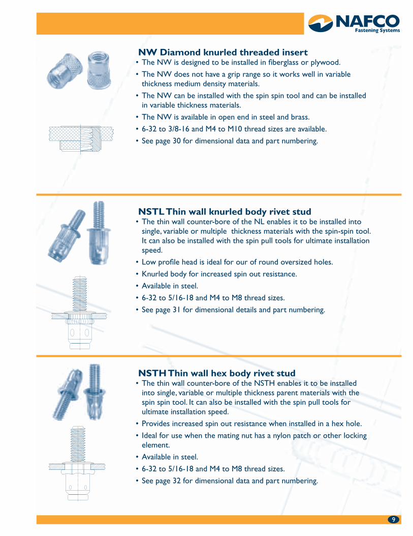
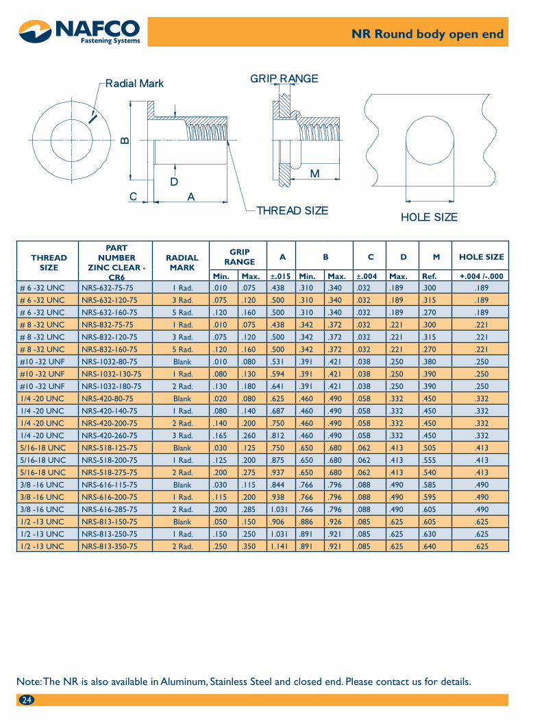
NR standard wall round body flat head The NR is based on the original rivet nut design. It has a standard •counter-bore wall and is installed only with the spin pull tools.
The NR is ideal for applications where it will be installed in the •bottom of a cabinet or frame for leg leveling screw attachment. The thicker flat head and standard counter-bore wall provides the best push out strength in this type of application. See page 47 for push out strength data.
Open end is available in steel, aluminum and stainless steel.•
6-32 to 1/2-13 thread sizes.•
See page 24 for dimensions and part numbers.•
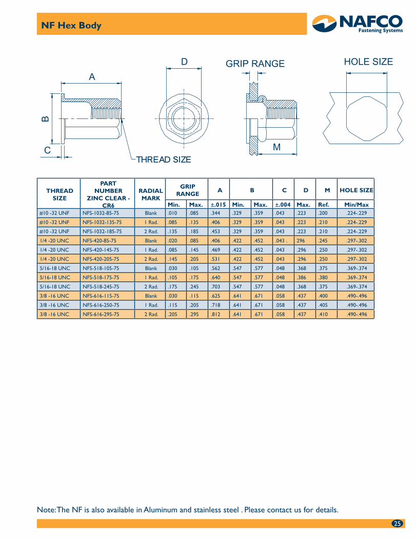
NF standard wall hex body flat head The NF is based on the original rivet nut design. It has a standard •counter-bore wall and is installed only with the spin pull tools.
The NR is ideal for applications requiring high spin out resistance. •The sharp corner full body hex and round internal counter bore resists collapsing under high torque loads.
Open end is available in steel, aluminum and stainless steel.•
6-32 to 3/8-16 thread sizes.•
See page 25 for dimensions and part numbers.•
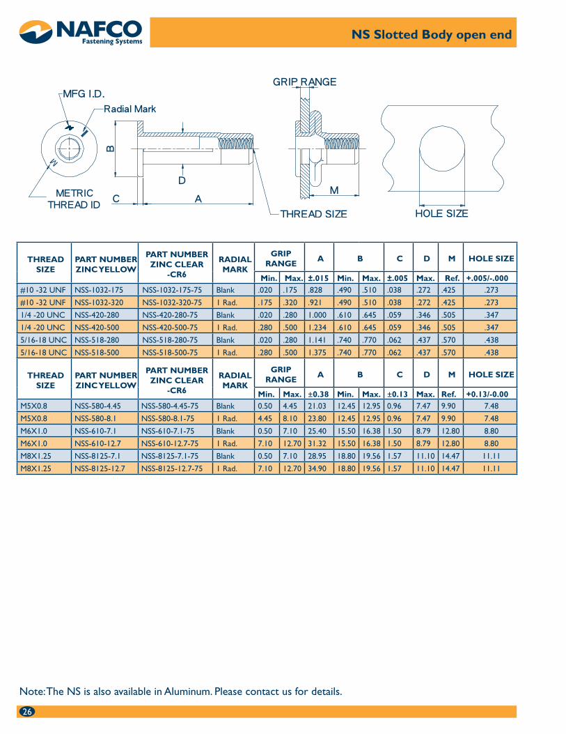
NS Slotted body flat head The NS Slotted body forms 4 large bearing surface legs on the •backside of the parent material providing the best all around pull out strength. It is installed using the SP999 long stroke spin pull tool.
The unique double wall counter-bore wall enables the NS to have the •widest grip range of any rivet nut fastener.
The wide spread of the legs on the backside eliminates the need for •backing washers in soft plastics making the NS ideal for applications in blow molded and injection molded plastic.
The NS is installed with the SP 999 long stroke spin pull tool. •
The NS is available in steel.•
10-32 to 5/16-18 and M5 to M8 in two grip sizes. •
See page 26 for dimensional data and part numbers.•
777
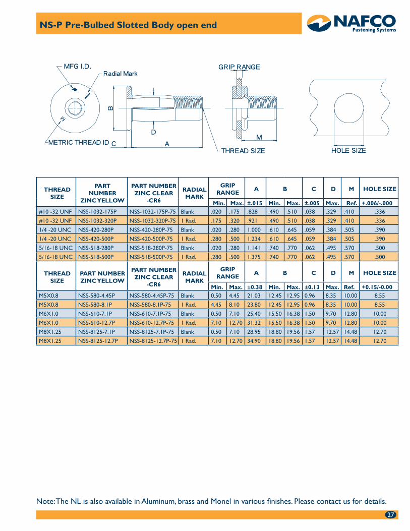
NS-P Pre-bulb slotted body flat head The NS Pre-bulb slotted body forms 4 large bearing surface legs on the •backside of the parent material providing the best all around pull out strength.
The pre-bulbed body allows the NS-P to be installed with the spin •spin tools in single, variable or multiple thickness materials without adjustment for parent material thickness. This makes the NS-P ideal for materials such as rotational molded plastic and hand laid up fiberglass that will vary in thickness.
The NS is available in steel.•
10-32 to 5/16-18 and M5 to M8 thread sizes in two grip sizes.•
See page 27 for dimensional details and part numbers. •
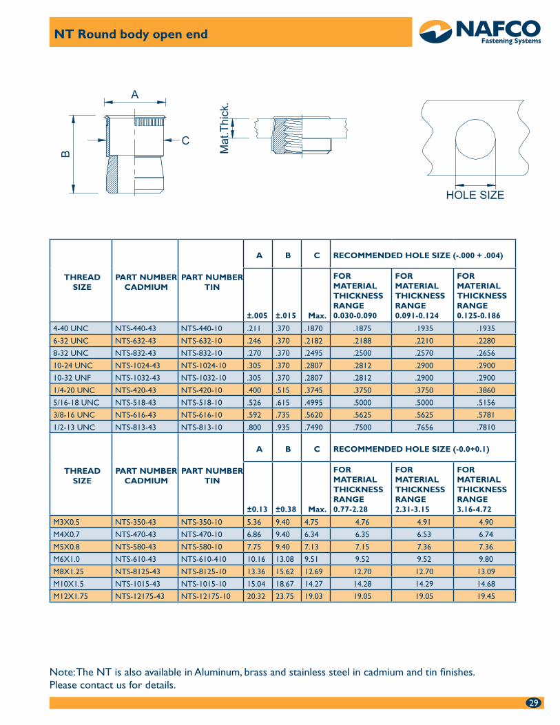
NT Knurled head threaded insert The NT has no grip range. It can be installed in any material thickness •but the hole size will vary in dimension and is based on the material thickness. The thicker the material the larger the hole.
Threads in this part are made oversized because the nut portion shrinks •as it is drawn into the sleeve. The installed thread is compatible with standard screws after installation.
The NT has the smallest backside protrusion of any rivet nut or •threaded insert making it ideal for applications with limited backside space requirements.
The NT is available in open and closed end in steel, aluminum, brass and •stainless steel.
4-40 to 1/2-13 and M3 to M12. •
See page 29 for dimensional details and part numbers.•
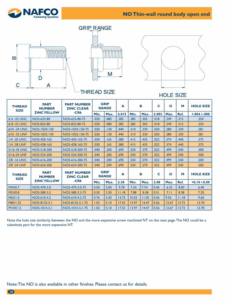
NO thin wall round body thin head The thin wall counter-bore of the NO enables it to be installed into •single, variable or multiple thickness parent materials with the spin spin tool. It can also be installed with the spin pull tools for ultimate installation speed.
The thin head allows the NO to be installed near flush with no special •hole preparation
The NO makes an ideal replacement for the NT threaded insert because •it fits the NT hole size in most thread sizes.
Open end available in steel.•
6-32 to 3/8-16 and M4 to M10 thread sizes in various grip ranges.•
See page 28 for dimensional data and part numbering•
8
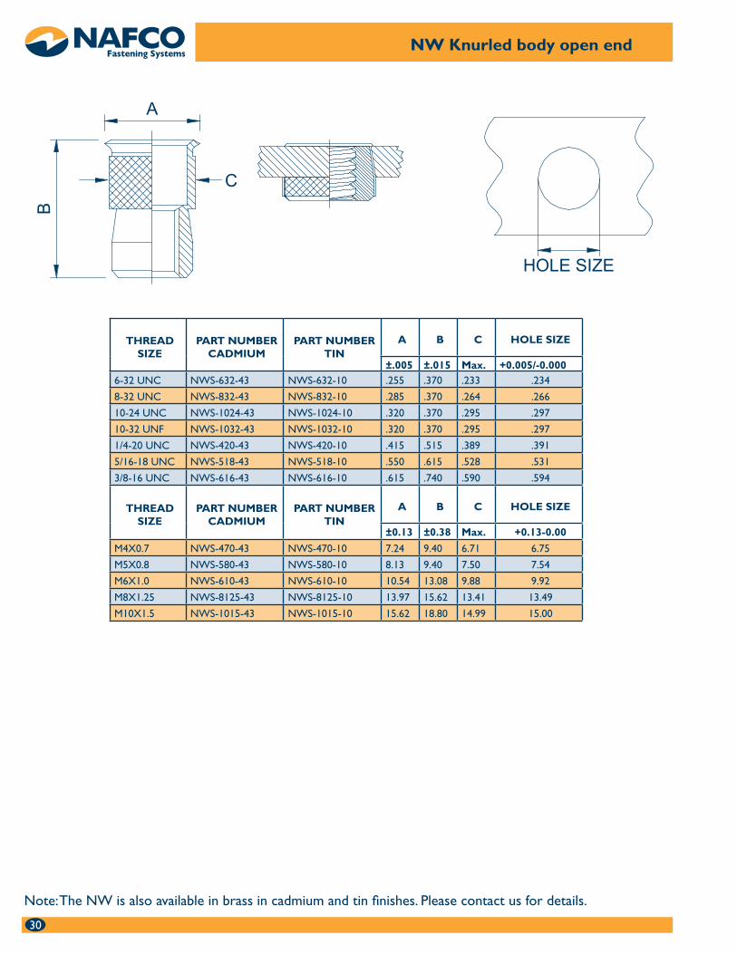
NW Diamond knurled threaded insert The NW is designed to be installed in fiberglass or plywood.•
The NW does not have a grip range so it works well in variable •thickness medium density materials.
The NW can be installed with the spin spin tool and can be installed •in variable thickness materials.
The NW is available in open end in steel and brass.•
6-32 to 3/8-16 and M4 to M10 thread sizes are available.•
See page 30 for dimensional data and part numbering.•
99
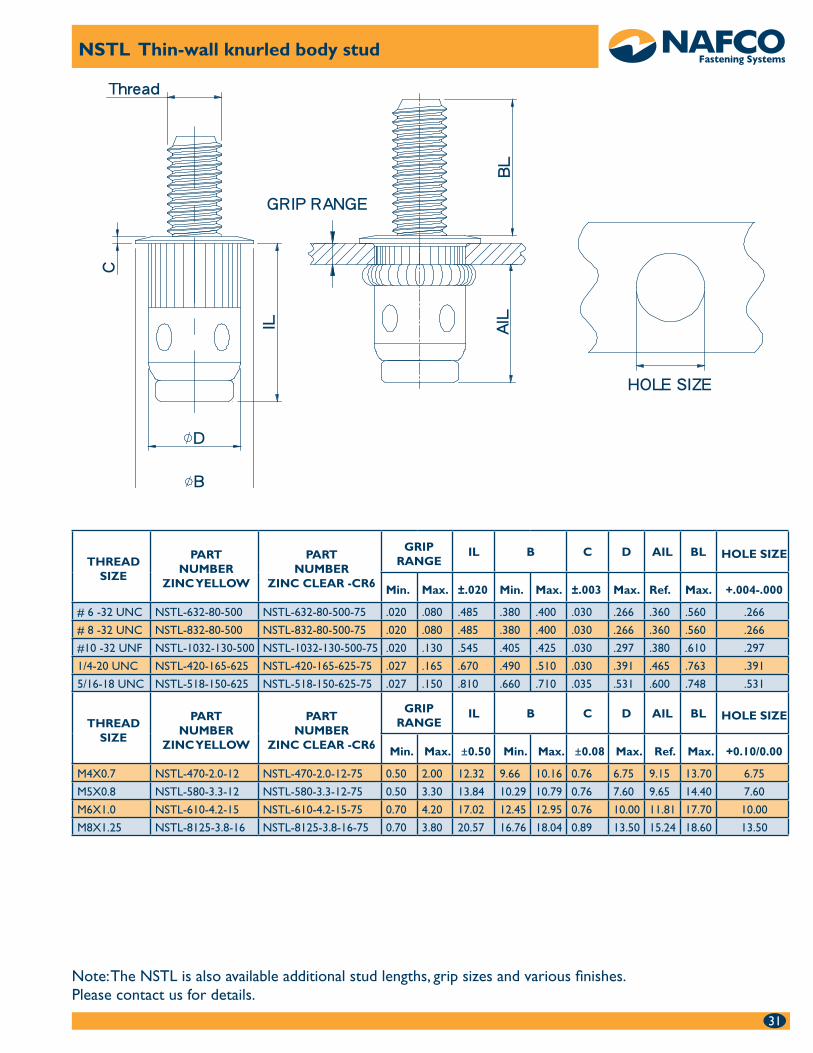
NSTL Thin wall knurled body rivet stud The thin wall counter-bore of the NL enables it to be installed into •single, variable or multiple thickness materials with the spin-spin tool. It can also be installed with the spin pull tools for ultimate installation speed.
Low profile head is ideal for our of round oversized holes.•
Knurled body for increased spin out resistance.•
Available in steel.•
6-32 to 5/16-18 and M4 to M8 thread sizes.•
See page 31 for dimensional details and part numbering.•
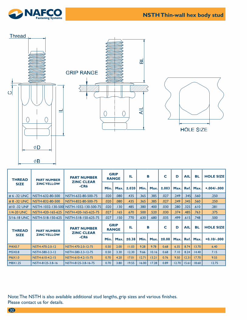
NSTH Thin wall hex body rivet stud The thin wall counter-bore of the NSTH enables it to be installed •into single, variable or multiple thickness parent materials with the spin spin tool. It can also be installed with the spin pull tools for ultimate installation speed.
Provides increased spin out resistance when installed in a hex hole.•
Ideal for use when the mating nut has a nylon patch or other locking •element.
Available in steel.•
6-32 to 5/16-18 and M4 to M8 thread sizes. •
See page 32 for dimensional data and part numbering.•
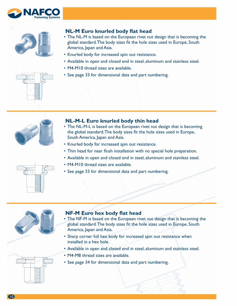
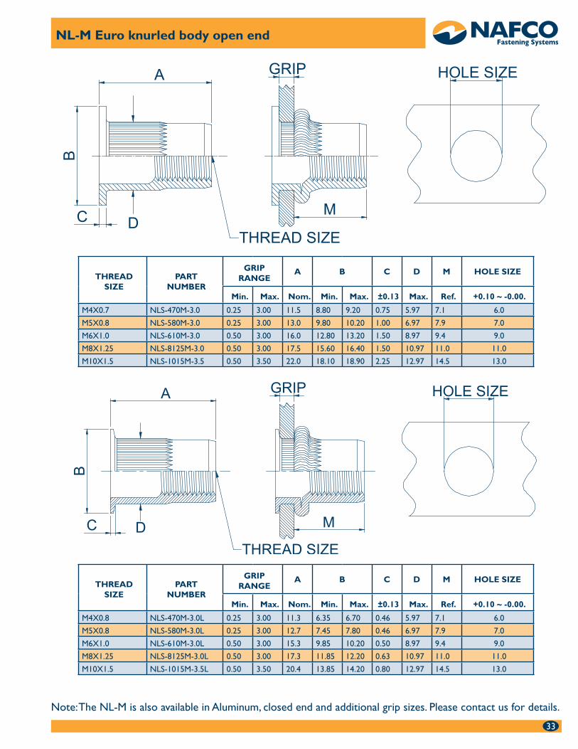
NL-M Euro knurled body flat head The NL-M is based on the European rivet nut design that is becoming the •global standard. The body sizes fit the hole sizes used in Europe, South America, Japan and Asia.
Knurled body for increased spin out resistance.•
Available in open and closed end in steel, aluminum and stainless steel.•
M4-M10 thread sizes are available.•
See page 33 for dimensional data and part numbering.•
10
NL-M-L Euro knurled body thin head The NL-M-L is based on the European rivet nut design that is becoming •the global standard. The body sizes fit the hole sizes used in Europe, South America, Japan and Asia.
Knurled body for increased spin out resistance.•
Thin head for near flush installation with no special hole preparation.•
Available in open and closed end in steel, aluminum and stainless steel.•
M4-M10 thread sizes are available.•
See page 33 for dimensional data and part numbering.•
NF-M Euro hex body flat head The NF-M is based on the European rivet nut design that is becoming the •global standard. The body sizes fit the hole sizes used in Europe, South America, Japan and Asia.
Sharp corner full hex body for increased spin out resistance when •installed in a hex hole.
Available in open and closed end in steel, aluminum and stainless steel.•
M4-M8 thread sizes are available.•
See page 34 for dimensional data and part numbering.•
NF-M-L Euro hex body thin head The NF-M-L is based on the European rivet nut design that is •becoming the global standard. The body sizes fit the hole sizes used in Europe, South America, Japan and Asia.
Thin head for near flush installation with no special hole preparation.•
Sharp corner full hex body for increased spin out resistance when •installed in a hex hole.
Available in open and closed end in steel, aluminum and stainless.•
M4-M8 thread sizes are available.•
See page 34 for dimensional data and part numbering.•
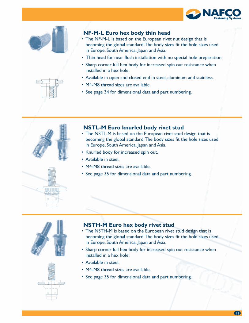
NSTL-M Euro knurled body rivet stud The NSTL-M is based on the European rivet stud design that is •becoming the global standard. The body sizes fit the hole sizes used in Europe, South America, Japan and Asia.
Knurled body for increased spin out.•
Available in steel.•
M4-M8 thread sizes are available.•
See page 35 for dimensional data and part numbering.•
NSTH-M Euro hex body rivet stud The NSTH-M is based on the European rivet stud design that is •becoming the global standard. The body sizes fit the hole sizes used in Europe, South America, Japan and Asia.
Sharp corner full hex body for increased spin out resistance when •installed in a hex hole.
Available in steel.•
M4-M8 thread sizes are available.•
See page 35 for dimensional data and part numbering.•
1111
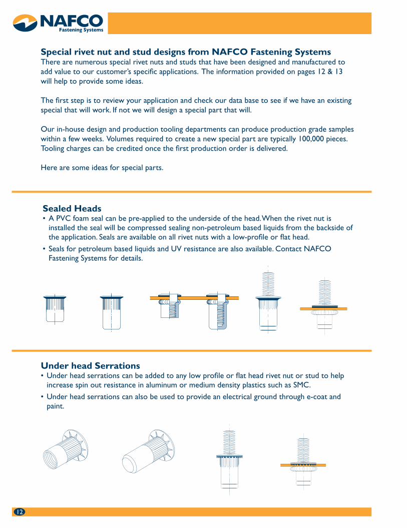
Sealed Heads A PVC foam seal can be pre-applied to the underside of the head. When the rivet nut is •installed the seal will be compressed sealing non-petroleum based liquids from the backside of the application. Seals are available on all rivet nuts with a low-profile or flat head.
Seals for petroleum based liquids and UV resistance are also available. Contact NAFCO •Fastening Systems for details.
12
Special rivet nut and stud designs from NAFCO Fastening SystemsThere are numerous special rivet nuts and studs that have been designed and manufactured to add value to our customer’s specific applications. The information provided on pages 12 & 13 will help to provide some ideas.
The first step is to review your application and check our data base to see if we have an existing special that will work. If not we will design a special part that will.
Our in-house design and production tooling departments can produce production grade samples within a few weeks. Volumes required to create a new special part are typically 100,000 pieces. Tooling charges can be credited once the first production order is delivered.
Here are some ideas for special parts.
Under head Serrations Under head serrations can be added to any low profile or flat head rivet nut or stud to help •increase spin out resistance in aluminum or medium density plastics such as SMC.
Under head serrations can also be used to provide an electrical ground through e-coat and •paint.
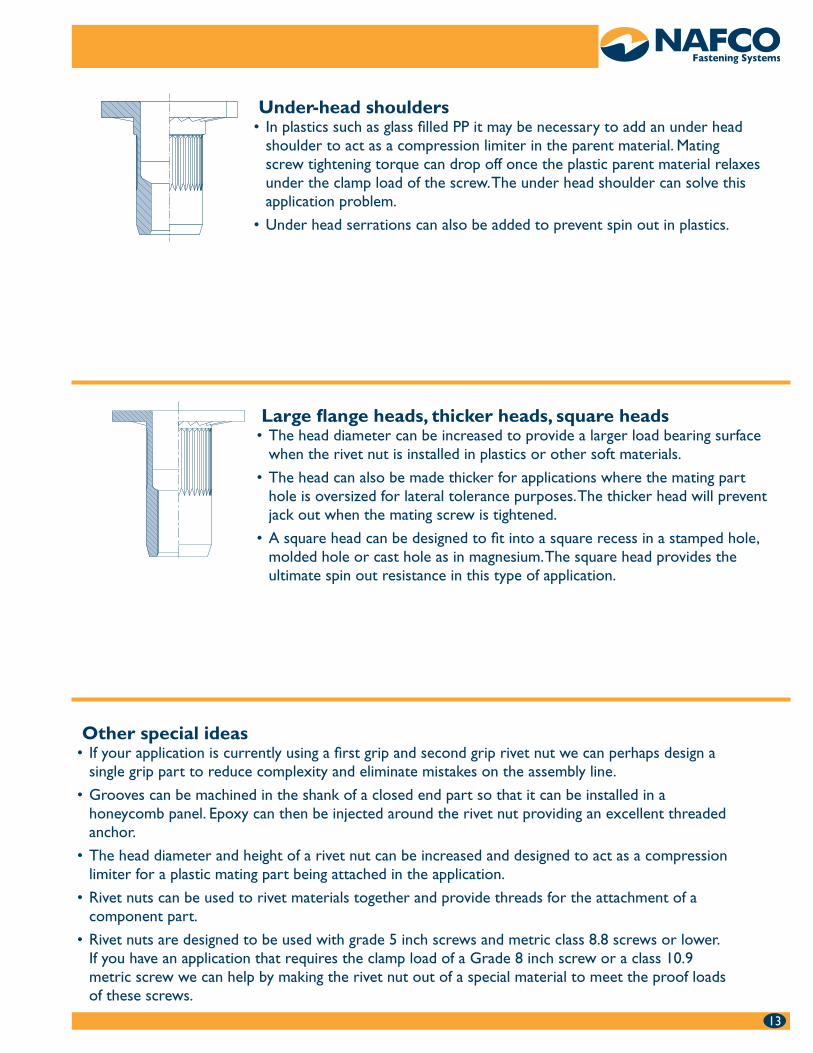
Under-head shoulders In plastics such as glass filled PP it may be necessary to add an under head •shoulder to act as a compression limiter in the parent material. Mating screw tightening torque can drop off once the plastic parent material relaxes under the clamp load of the screw. The under head shoulder can solve this application problem.
Under head serrations can also be added to prevent spin out in plastics.•
Large flange heads, thicker heads, square heads The head diameter can be increased to provide a larger load bearing surface •when the rivet nut is installed in plastics or other soft materials.
The head can also be made thicker for applications where the mating part •hole is oversized for lateral tolerance purposes. The thicker head will prevent jack out when the mating screw is tightened.
A square head can be designed to fit into a square recess in a stamped hole, •molded hole or cast hole as in magnesium. The square head provides the ultimate spin out resistance in this type of application.
Other special ideas If your application is currently using a first grip and second grip rivet nut we can perhaps design a •single grip part to reduce complexity and eliminate mistakes on the assembly line.
Grooves can be machined in the shank of a closed end part so that it can be installed in a •honeycomb panel. Epoxy can then be injected around the rivet nut providing an excellent threaded anchor.
The head diameter and height of a rivet nut can be increased and designed to act as a compression •limiter for a plastic mating part being attached in the application.
Rivet nuts can be used to rivet materials together and provide threads for the attachment of a •component part.
Rivet nuts are designed to be used with grade 5 inch screws and metric class 8.8 screws or lower. •If you have an application that requires the clamp load of a Grade 8 inch screw or a class 10.9 metric screw we can help by making the rivet nut out of a special material to meet the proof loads of these screws.
1313
14
Parent Material Drilled HolesPunched-Pierced-Laser
cut holesRound holes with a stamped
or molded square recess
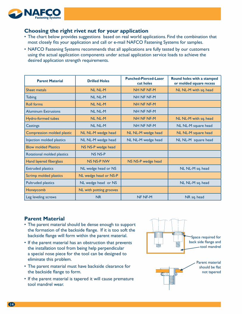
Sheet metals NL NL-M NH NF NF-M NL NL-M with sq. head
Tubing NL NL-M NH NF NF-M
Roll forms NL NL-M NH NF NF-M
Aluminum Extrusions NL NL-M NH NF NF-M
Hydro-formed tubes NL NL-M NH NF NF-M NL NL-M with sq. head
Castings NL NL-M NH NF NF-M NL NL-M square head
Compression molded plastic NL NL-M wedge head NL NL-M wedge head NL NL-M square head
Injection molded plastics NL NL-M wedge head NL NL-M wedge head NL NL-M square head
Blow molded Plastics NS NS-P wedge head
Rotational molded plastics NS NS-P
Hand layered fiberglass NS NS-P NW NS NS-P wedge head
Extruded plastics NL wedge head or NS NL NL-M sq. head
Scrimp molded plastics NL wedge head or NS-P
Pultruded plastics NL wedge head or NS NL NL-M sq. head
Honeycomb NL with potting grooves
Leg leveling screws NR NF NF-M NR sq. head
Parent Material The parent material should be dense enough to support •the formation of the backside flange. If it is too soft the backside flange will form within the parent material.
If the parent material has an obstruction that prevents •the installation tool from being help perpendicular a special nose piece for the tool can be designed to eliminate this problem.
The parent material must have backside clearance for •the backside flange to form.
If the parent material is tapered it will cause premature •tool mandrel wear.
Choosing the right rivet nut for your application The chart below provides suggestions based on real world applications. Find the combination that •most closely fits your application and call or e-mail NAFCO Fastening Systems for samples.
NAFCO Fastening Systems recommends that all applications are fully tested by our customers •using the actual application components under actual application service loads to achieve the desired application strength requirements.
Space required for back side flange and
tool mandrel
Parent material should be flat
not tapered
15
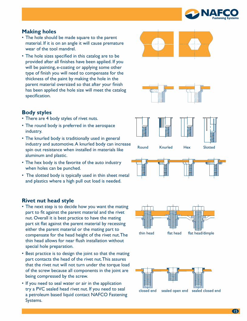
Rivet nut head style The next step is to decide how you want the mating •part to fit against the parent material and the rivet nut. Overall it is best practice to have the mating part sit flat against the parent material by recessing either the parent material or the mating part to compensate for the head height of the rivet nut. The thin head allows for near flush installation without special hole preparation.
Best practice is to design the joint so that the mating •part contacts the head of the rivet nut. This assures that the rivet nut will not turn under the torque load of the screw because all components in the joint are being compressed by the screw.
If you need to seal water or air in the application •try a PVC sealed head rivet nut. If you need to seal a petroleum based liquid contact NAFCO Fastening Systems.
Making holes The hole should be made square to the parent •material. If it is on an angle it will cause premature wear of the tool mandrel.
The hole sizes specified in this catalog are to be •provided after all finishes have been applied. If you will be painting, e-coating or applying some other type of finish you will need to compensate for the thickness of the paint by making the hole in the parent material oversized so that after your finish has been applied the hole size will meet the catalog specification.
Body stylesThere are 4 body styles of rivet nuts. •
The round body is preferred in the aerospace •industry.
The knurled body is traditionally used in general •industry and automotive. A knurled body can increase spin out resistance when installed in materials like aluminum and plastic.
The hex body is the favorite of the auto industry •when holes can be punched.
The slotted body is typically used in thin sheet metal •and plastics where a high pull out load is needed.
Round Knurled Hex Slotted
thin head flat head flat head/dimple
closed end sealed open end sealed closed end
16
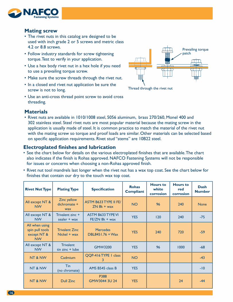
Materials Rivet nuts are available in 1010/1008 steel, 5056 aluminum, brass 270/260, Monel 400 and •302 stainless steel. Steel rivet nuts are most popular material because the mating screw in the application is usually made of steel. It is common practice to match the material of the rivet nut with the mating screw so torque and proof loads are similar. Other materials can be selected based on specific application requirements. Rivet stud “stems” are 10B22 steel.
Rivet Nut Type Plating Type SpecificationRohas
Compliant
Hours to white
corrosion
Hours to red
corrosion
Dash Number
All except NT & NW
Zinc yellow dichromate +
wax
ASTM B633 TYPE II FE/ZN 8k + wax
NO 96 240 None
All except NT & NW
Trivalent zinc + sealer + wax
ASTM B633 TYPE VI FE/ZN 8k + wax
YES 120 240 -75
All when using spin pull tools except NT &
NW
Trivalent Zinc Nickel + wax
MercedesDBL8451.76 + Wax
YES 240 720 -59
All except NT & NW
Trivalent tin zinc + lube
GMW3200 YES 96 1000 -68
NT & NW CadmiumQQP-416 TYPE 1 class
3NO -43
NT & NWTin
(no chromate)AMS B545 class B YES -10
NT & NW Dull ZincP388
GMW3044 3U 24 YES 24 -44
Mating screw The rivet nuts in this catalog are designed to be •used with inch grade 2 or 5 screws and metric class 4.2 or 8.8 screws.
Follow industry standards for screw tightening •torque. Test to verify in your application.
Use a hex body rivet nut in a hex hole if you need •to use a prevailing torque screw.
Make sure the screw threads through the rivet nut. •
In a closed end rivet nut application be sure the •screw is not to long.
Use an anti-cross thread point screw to avoid cross •threading.
Electroplated finishes and lubrication See the chart below for details on the various electroplated finishes that are available. The chart •also indicates if the finish is Rohas approved. NAFCO Fastening Systems will not be responsible for issues or concerns when choosing a non-Rohas approved finish.
Rivet nut tool mandrels last longer when the rivet nut has a wax top coat. See the chart below for •finishes that contain our dry to the touch wax top coat.
Prevailing torque patch
Thread through the rivet nut
17
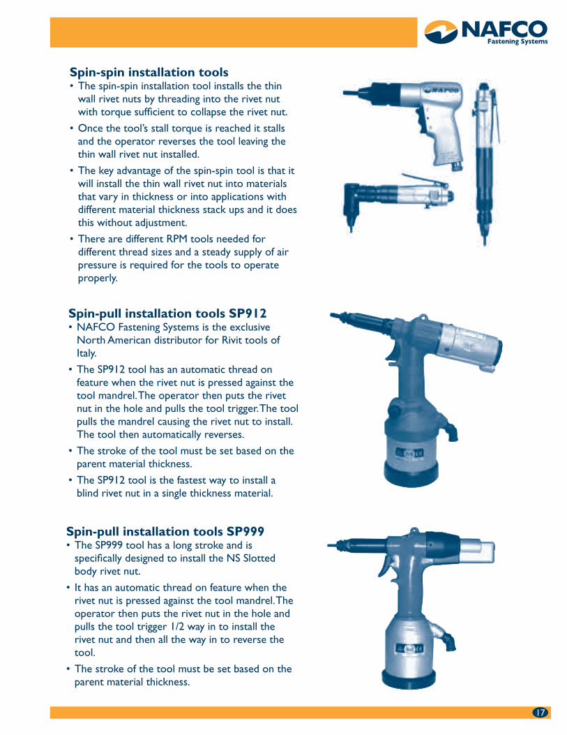
Spin-spin installation tools The spin-spin installation tool installs the thin •wall rivet nuts by threading into the rivet nut with torque sufficient to collapse the rivet nut.
Once the tool’s stall torque is reached it stalls •and the operator reverses the tool leaving the thin wall rivet nut installed.
The key advantage of the spin-spin tool is that it •will install the thin wall rivet nut into materials that vary in thickness or into applications with different material thickness stack ups and it does this without adjustment.
There are different RPM tools needed for •different thread sizes and a steady supply of air pressure is required for the tools to operate properly.
Spin-pull installation tools SP912 NAFCO Fastening Systems is the exclusive •North American distributor for Rivit tools of Italy.
The SP912 tool has an automatic thread on •feature when the rivet nut is pressed against the tool mandrel. The operator then puts the rivet nut in the hole and pulls the tool trigger. The tool pulls the mandrel causing the rivet nut to install. The tool then automatically reverses.
The stroke of the tool must be set based on the •parent material thickness.
The SP912 tool is the fastest way to install a •blind rivet nut in a single thickness material.
Spin-pull installation tools SP999 The SP999 tool has a long stroke and is •specifically designed to install the NS Slotted body rivet nut.
It has an automatic thread on feature when the •rivet nut is pressed against the tool mandrel. The operator then puts the rivet nut in the hole and pulls the tool trigger 1/2 way in to install the rivet nut and then all the way in to reverse the tool.
The stroke of the tool must be set based on the •parent material thickness.
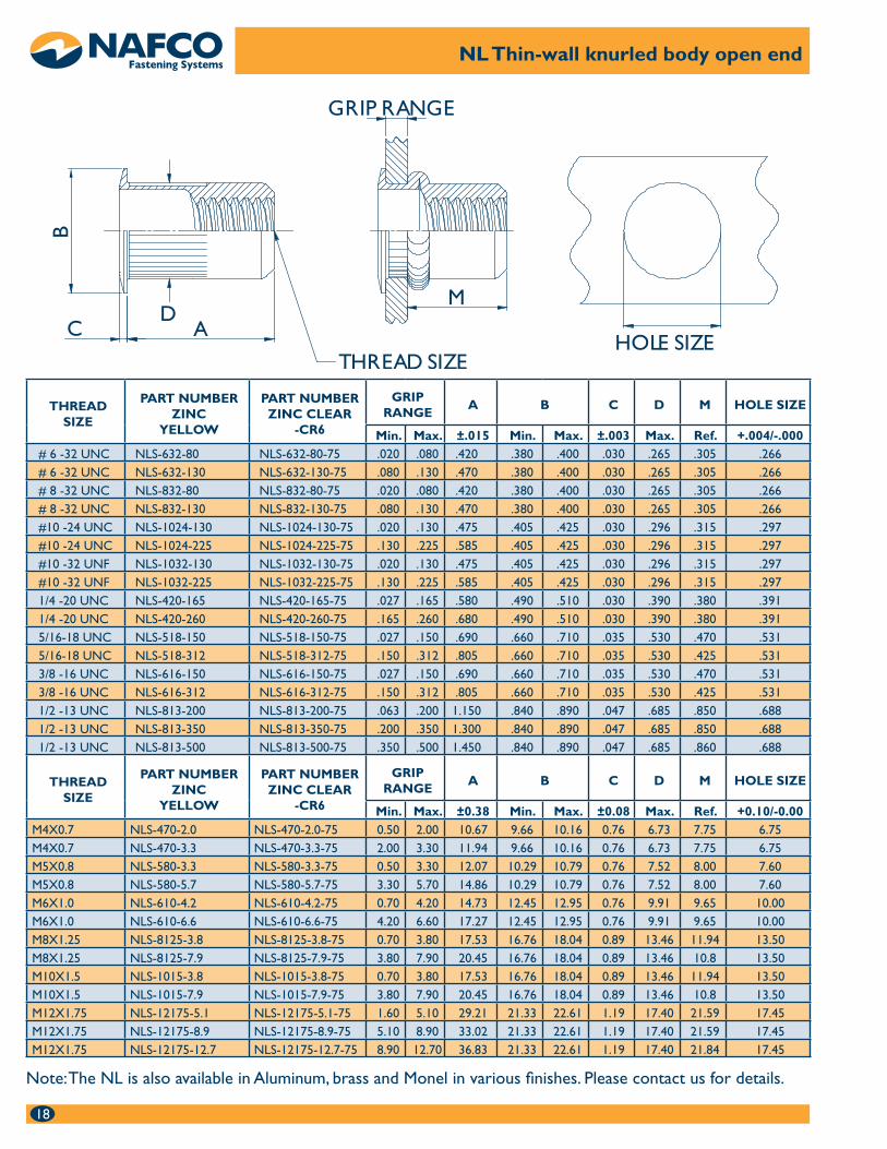
18
NL Thin-wall knurled body open end
Note: The NL is also available in Aluminum, brass and Monel in various finishes. Please contact us for details.
THREADSIZE
PART NUMBERZINC
YELLOW
PART NUMBERZINC CLEAR
-CR6
GRIPRANGE
A B C D M HOLE SIZE
Min. Max. ±.015 Min. Max. ±.003 Max. Ref. +.004/-.000# 6 -32 UNC NLS-632-80 NLS-632-80-75 .020 .080 .420 .380 .400 .030 .265 .305 .266# 6 -32 UNC NLS-632-130 NLS-632-130-75 .080 .130 .470 .380 .400 .030 .265 .305 .266# 8 -32 UNC NLS-832-80 NLS-832-80-75 .020 .080 .420 .380 .400 .030 .265 .305 .266# 8 -32 UNC NLS-832-130 NLS-832-130-75 .080 .130 .470 .380 .400 .030 .265 .305 .266#10 -24 UNC NLS-1024-130 NLS-1024-130-75 .020 .130 .475 .405 .425 .030 .296 .315 .297#10 -24 UNC NLS-1024-225 NLS-1024-225-75 .130 .225 .585 .405 .425 .030 .296 .315 .297#10 -32 UNF NLS-1032-130 NLS-1032-130-75 .020 .130 .475 .405 .425 .030 .296 .315 .297#10 -32 UNF NLS-1032-225 NLS-1032-225-75 .130 .225 .585 .405 .425 .030 .296 .315 .2971/4 -20 UNC NLS-420-165 NLS-420-165-75 .027 .165 .580 .490 .510 .030 .390 .380 .3911/4 -20 UNC NLS-420-260 NLS-420-260-75 .165 .260 .680 .490 .510 .030 .390 .380 .3915/16-18 UNC NLS-518-150 NLS-518-150-75 .027 .150 .690 .660 .710 .035 .530 .470 .5315/16-18 UNC NLS-518-312 NLS-518-312-75 .150 .312 .805 .660 .710 .035 .530 .425 .5313/8 -16 UNC NLS-616-150 NLS-616-150-75 .027 .150 .690 .660 .710 .035 .530 .470 .5313/8 -16 UNC NLS-616-312 NLS-616-312-75 .150 .312 .805 .660 .710 .035 .530 .425 .5311/2 -13 UNC NLS-813-200 NLS-813-200-75 .063 .200 1.150 .840 .890 .047 .685 .850 .6881/2 -13 UNC NLS-813-350 NLS-813-350-75 .200 .350 1.300 .840 .890 .047 .685 .850 .6881/2 -13 UNC NLS-813-500 NLS-813-500-75 .350 .500 1.450 .840 .890 .047 .685 .860 .688
THREADSIZE
PART NUMBERZINC
YELLOW
PART NUMBERZINC CLEAR
-CR6
GRIPRANGE
A B C D M HOLE SIZE
Min. Max. ±0.38 Min. Max. ±0.08 Max. Ref. +0.10/-0.00M4X0.7 NLS-470-2.0 NLS-470-2.0-75 0.50 2.00 10.67 9.66 10.16 0.76 6.73 7.75 6.75M4X0.7 NLS-470-3.3 NLS-470-3.3-75 2.00 3.30 11.94 9.66 10.16 0.76 6.73 7.75 6.75M5X0.8 NLS-580-3.3 NLS-580-3.3-75 0.50 3.30 12.07 10.29 10.79 0.76 7.52 8.00 7.60M5X0.8 NLS-580-5.7 NLS-580-5.7-75 3.30 5.70 14.86 10.29 10.79 0.76 7.52 8.00 7.60M6X1.0 NLS-610-4.2 NLS-610-4.2-75 0.70 4.20 14.73 12.45 12.95 0.76 9.91 9.65 10.00M6X1.0 NLS-610-6.6 NLS-610-6.6-75 4.20 6.60 17.27 12.45 12.95 0.76 9.91 9.65 10.00M8X1.25 NLS-8125-3.8 NLS-8125-3.8-75 0.70 3.80 17.53 16.76 18.04 0.89 13.46 11.94 13.50M8X1.25 NLS-8125-7.9 NLS-8125-7.9-75 3.80 7.90 20.45 16.76 18.04 0.89 13.46 10.8 13.50M10X1.5 NLS-1015-3.8 NLS-1015-3.8-75 0.70 3.80 17.53 16.76 18.04 0.89 13.46 11.94 13.50M10X1.5 NLS-1015-7.9 NLS-1015-7.9-75 3.80 7.90 20.45 16.76 18.04 0.89 13.46 10.8 13.50M12X1.75 NLS-12175-5.1 NLS-12175-5.1-75 1.60 5.10 29.21 21.33 22.61 1.19 17.40 21.59 17.45M12X1.75 NLS-12175-8.9 NLS-12175-8.9-75 5.10 8.90 33.02 21.33 22.61 1.19 17.40 21.59 17.45M12X1.75 NLS-12175-12.7 NLS-12175-12.7-75 8.90 12.70 36.83 21.33 22.61 1.19 17.40 21.84 17.45
19
NL Thin-Wall knurled body closed end
Note: The NL is also available in Aluminum, brass and Monel in various finishes. Please contact us for details.
THREADSIZE
PART NUMBERZINC
YELLOW
PART NUMBERZINC CLEAR
-CR6
GRIPRANGE
A B C D M FTD HOLE SIZE
Min. Max. ±.015 Min. Max. ±.003 Max. Ref. Max. +.004/-.000# 6 -32 UNC NLS-632-80B NLS-632-80B-75 .020 .080 .740 .380 .400 .030 .265 .640 .610 .266# 6 -32 UNC NLS-632-130B NLS-632-130B-75 .080 .130 .740 .380 .400 .030 .265 .580 .670 .266# 8 -32 UNC NLS-832-80B NLS-832-80B-75 .020 .080 .740 .380 .400 .030 .265 .640 .610 .266# 8 -32 UNC NLS-832-130B NLS-832-130B-75 .080 .130 .740 .380 .400 .030 .265 .580 .670 .266#10 -24 UNC NLS-024-130B NLS-024-130B-75 .020 .130 .990 .405 .425 .030 .296 .845 .730 .297#10 -24 UNC NLS-1024-225B NLS-1024-225B-75 .130 .225 .990 .405 .425 .030 .296 .735 .840 .297#10 -32 UNF NLS-1032-130B NLS-1032-130B-75 .020 .130 .990 .405 .425 .030 .296 .845 .730 .297#10 -32 UNF NLS-1032-225B NLS-1032-225B-75 .130 .225 .990 .405 .425 .030 .296 .735 .840 .2971/4 -20 UNC NLS-420-165B NLS-420-165B-75 .027 .165 1.190 .490 .510 .030 .390 1.005 .895 .3911/4 -20 UNC NLS-420-260B NLS-420-260B-75 .165 .260 1.190 .490 .510 .030 .390 .905 1.035 .3915/16-18 UNC NLS-518-150B NLS-518-150B-75 .027 .150 1.390 .660 .710 .035 .530 1.175 .995 .5315/16-18 UNC NLS-518-312B NLS-518-312B-75 .150 .312 1.390 .660 .710 .035 .530 1.025 1.120 .5313/8 -16 UNC NLS-616-150B NLS-616-150B-75 .027 .150 1.390 .660 .710 .035 .530 1.175 .995 .5313/8 -16 UNC NLS-616-312B NLS-616-312B-75 .150 .312 1.390 .660 .710 .035 .530 1.025 1.120 .531
THREADSIZE
PART NUMBERZINC
YELLOW
PART NUMBERZINC CLEAR
-CR6
GRIPRANGE
A B C D M FTD HOLE SIZE
Min. Max. ±0.38 Min. Max. ±0.08 Max. Ref. Max. +0.10/-0.00M4X0.7 NLS-470-2.0B NLS-470-2.0B-75 0.50 2.00 18.80 9.66 10.16 0.76 6.73 16.26 15.49 6.75M4X0.7 NLS-470-3.3B NLS-470-3.3B-75 2.00 3.30 18.80 9.66 10.16 0.76 6.73 14.73 17.02 6.75M5X0.8 NLS-580-3.3B NLS-580-3.3B-75 0.50 3.30 25.15 10.29 10.79 0.76 7.52 21.46 18.54 7.60M5X0.8 NLS-580-5.7B NLS-580-5.7B-75 3.30 5.70 25.15 10.29 10.79 0.76 7.52 18.67 21.34 7.60M6X1.0 NLS-610-4.2B NLS-610-4.2B-75 0.70 4.20 30.23 12.45 12.95 0.76 9.91 25.53 22.73 10.00M6X1.0 NLS-610-6.6B NLS-610-6.6B-75 4.20 6.60 30.23 12.45 12.95 0.76 9.91 22.99 26.29 10.00M8X1.25 NLS-8125-3.8B NLS-8125-3.8B-75 0.70 3.80 35.31 16.76 18.03 0.89 13.46 29.85 25.27 13.50M8X1.25 NLS-8125-7.9B NLS-8125-7.9B-75 3.80 7.90 35.31 16.76 18.03 0.89 13.46 26.04 28.45 13.50M10X1.5 NLS-1015-3.8B NLS-1015-3.8B-75 0.70 3.80 35.31 16.76 18.03 0.89 13.46 29.85 25.27 13.50M10X1.5 NLS-1015-7.9B NLS-1015-7.9B-75 3.80 7.90 35.31 16.76 18.03 0.89 13.46 26.04 28.45 13.50
20
NK Thin-wall knurled body open end
Note: The NK is also available in Aluminum, brass and Monel in various finishes. Please contact us for details.
THREADSIZE
PART NUMBERZINC
YELLOW
PART NUMBERZINC CLEAR
-CR6
GRIPRANGE
A B C D M HOLE SIZE
Min. Max. ±.015 Min. Max. ±.003 Max. Ref. +.004/-.000# 6 -32 UNC NKS-632-80 NKS-632-80-75 .020 .080 .420 .300 .320 .019 .265 .305 .266# 6 -32 UNC NKS-632-130 NKS-632-130-75 .080 .130 .470 .300 .320 .019 .265 .305 .266# 8 -32 UNC NKS-832-80 NKS-832-80-75 .020 .080 .420 .300 .320 .019 .265 .305 .266# 8 -32 UNC NKS-832-130 NKS-832-130-75 .080 .130 .470 .300 .320 .019 .265 .305 .266#10 -24 UNC NKS-1024-130 NKS-1024-130-75 .020 .130 .475 .330 .350 .019 .296 .315 .297#10 -24 UNC NKS-1024-225 NKS-1024-225-75 .130 .225 .585 .330 .350 .019 .296 .315 .297#10 -32 UNF NKS-1032-130 NKS-1032-130-75 .020 .130 .475 .330 .350 .019 .296 .315 .297#10 -32 UNF NKS-1032-225 NKS-1032-225-75 .130 .225 .585 .330 .350 .019 .296 .315 .2971/4 -20 UNC NKS-420-165 NKS-420-165-75 .027 .165 .580 .445 .465 .022 .390 .380 .3911/4 -20 UNC NKS-420-260 NKS-420-260-75 .165 .260 .680 .445 .465 .022 .390 .380 .3915/16-18 UNC NKS-518-150 NKS-518-150-75 .027 .150 .690 .581 .609 .022 .530 .470 .5315/16-18 UNC NKS-518-312 NKS-518-312-75 .150 .312 .805 .581 .609 .022 .530 .425 .5313/8 -16 UNC NKS-616-150 NKS-616-150-75 .027 .150 .690 .581 .609 .022 .530 .470 .5313/8 -16 UNC NKS-616-312 NKS-616-312-75 .150 .312 .805 .581 .609 .022 .530 .425 .531
THREADSIZE
PART NUMBERZINC
YELLOW
PART NUMBERZINC CLEAR
-CR6
GRIPRANGE
A B C D M HOLE SIZE
Min. Max. ±0.38 Min. Max. ±0.08 Max. Ref. +0.10/-0.00M4 X0.7 NKS-470-2.0 NKS-470-2.0-75 0.50 2.00 10.67 7.62 8.12 0.48 6.73 7.75 6.75M4 X0.7 NKS-470-3.3 NKS-470-3.3-75 2.00 3.30 11.94 7.62 8.12 0.48 6.73 7.75 6.75M5 X0.8 NKS-580-3.3 NKS-580-3.3-75 0.50 3.30 12.07 8.39 8.89 0.48 7.52 8.00 7.60M5 X0.8 NKS-580-5.7 NKS-580-5.7-75 3.30 5.70 14.86 8.39 8.89 0.48 7.52 8.00 7.60M6 X1.0 NKS-610-4.2 NKS-610-4.2-75 0.70 4.20 14.73 11.31 11.81 0.55 9.91 9.65 10.00M6 X1.0 NKS-610-6.6 NKS-610-6.6-75 4.20 6.60 17.27 11.31 11.81 0.55 9.91 9.65 10.00M8 X1.25 NKS-8125-3.8 NKS-8125-3.8-75 0.70 3.80 17.53 14.79 15.46 0.55 13.46 11.94 13.50M8 X1.25 NKS-8125-7.9 NKS-8125-7.9-75 3.80 7.90 20.45 14.79 15.46 0.55 13.46 10.80 13.50M10X1.5 NKS-1015-3.8 NKS-1015-3.8-75 0.70 3.80 17.53 14.79 15.46 0.55 13.46 11.94 13.50M10X1.5 NKS-1015-7.9 NKS-1015-7.9-75 3.80 7.90 20.45 14.79 15.46 0.55 13.46 10.80 13.50
21
NK Thin-wall knurled body closed end
Note: The NK is also available in Aluminum, brass and Monel in various finishes. Please contact us for details.
THREADSIZE
PART NUMBERZINC
YELLOW
PART NUMBERZINC CLEAR
-CR6
GRIPRANGE
A B C D M FTD HOLE SIZE
Min. Max. ±.015 Min. Max. ±.003 Max. Ref. Max. ±.004/.000# 6 -32 UNC NKS-632-80B NKS-632-80B-75 .020 .080 .740 .300 .320 .019 .265 .640 .610 .266
# 6 -32 UNC NKS-632-130B NKS-632-130B-75 .080 .130 .740 .300 .320 .019 .265 .580 .670 .266
# 8 -32 UNC NKS-832-80B NKS-832-80B-75 .020 .080 .740 .300 .320 .019 .265 .640 .610 .266
# 8 -32 UNC NKS-832-130B NKS-832-130B-75 .080 .130 .740 .300 .320 .019 .265 .580 .670 .266
#10 -24 UNC NKS-1024-130B NKS-1024-130B-75 .020 .130 .990 .330 .350 .019 .296 .845 .730 .297
#10 -24 UNC NKS-1024-225B NKS-1024-225B-75 .130 .225 .990 .330 .350 .019 .296 .735 .840 .297
#10 -32 UNF NKS-1032-130B NKS-1032-130B-75 .020 .130 .990 .330 .350 .019 .296 .845 .730 .297
#10 -32 UNF NKS-1032-225B NKS-1032-225B-75 .130 .225 .990 .330 .350 .019 .296 .735 .840 .297
1/4 -20 UNC NKS-420-165B NKS-420-165B-75 .027 .165 1.190 .445 .465 .022 .390 1.005 .895 .391
1/4 -20 UNC NKS-420-260B NKS-420-260B-75 .165 .260 1.190 .445 .465 .022 .390 .905 1.035 .391
5/16-18 UNC NKS-518-150B NKS-518-150B-75 .027 .150 1.390 .581 .609 .022 .530 1.175 .995 .531
5/16-18 UNC NKS-518-312B NKS-518-312B-75 .150 .312 1.390 .581 .609 .022 .530 1.025 1.120 .531
3/8 -16 UNC NKS-616-150B NKS-616-150B-75 .027 .150 1.390 .581 .609 .022 .530 1.175 .995 .531
3/8 -16 UNC NKS-616-312B NKS-616-312B-75 .150 .312 1.390 .581 .609 .022 .530 1.025 1.120 .531
THREADSIZE
PART NUMBERZINC
YELLOW
PART NUMBERZINC CLEAR
-CR6
GRIPRANGE
A B C D M FTD HOLE SIZE
Min. Max. ±0.38 Min. Max. ±0.08 Max. Ref. Max. ±0.10/0.00M4 X0.7 NKS-470-2.0B NKS-470-2.0B-75 0.50 2.00 18.80 7.62 8.12 0.48 6.73 16.26 15.49 6.75
M4 X0.7 NKS-470-3.3B NKS-470-3.3B-75 2.00 3.30 18.80 7.62 8.12 0.48 6.73 14.73 17.02 6.75
M5 X0.8 NKS-580-3.3B NKS-580-3.3B-75 0.50 3.30 25.15 8.39 8.89 0.48 7.52 21.46 18.54 7.60
M5 X0.8 NKS-580-5.7B NKS-580-5.7B-75 3.30 5.70 25.15 8.39 8.89 0.48 7.52 18.67 21.34 7.60
M6 X1.0 NKS-610-4.2B NKS-610-4.2B-75 0.70 4.20 30.23 11.31 11.81 0.55 9.91 25.53 22.73 10.00
M6 X1.0 NKS-610-6.6B NKS-610-6.6B-75 4.20 6.60 30.23 11.31 11.81 0.55 9.91 22.99 26.29 10.00
M8 X1.25 NKS-8125-3.8B NKS-8125-3.8B-75 0.70 3.80 35.31 14.79 15.46 0.55 13.46 29.85 25.27 13.50
M8 X1.25 NKS-8125-7.9B NKS-8125-7.9B-75 3.80 7.90 35.31 14.79 15.46 0.55 13.46 26.04 28.45 13.50
M10X1.5 NKS-1015-3.8B NKS-1015-3.8B-75 0.70 3.80 35.31 14.79 15.46 0.55 13.46 29.85 25.27 13.50
M10X1.5 NKS-1015-7.9B NKS-1015-7.9B-75 3.80 7.90 35.31 14.79 15.46 0.55 13.46 26.04 28.45 13.50
22
THREADSIZE
PART NUMBERZINC
YELLOW
PART NUMBERZINC CLEAR
-CR6
GRIPRANGE
A B C D M HOLE SIZE
Min. Max. ±.015 Min. Max. ±.003 Max. Ref. ±.004/-.000# 6 -32 UNC NHS-632-80 NHS-632-80-75 .020 .080 .385 .365 .385 .027 .249 .295 .250
# 6 -32 UNC NHS-632-130 NHS-632-130-75 .080 .130 .435 .365 .385 .027 .249 .295 .250
# 8 -32 UNC NHS-832-80 NHS-832-80-75 .020 .080 .385 .365 .385 .027 .249 .295 .250
# 8 -32 UNC NHS-832-130 NHS-832-130-75 .080 .130 .435 .365 .385 .027 .249 .295 .250
#10 -24 UNC NHS-1024-130 NHS-1024-130-75 .020 .130 .435 .380 .400 .027 .280 .275 .281
#10 -24 UNC NHS-1024-225 NHS-1024-225-75 .130 .225 .535 .380 .400 .027 .280 .275 .281
#10 -32 UNF NHS-1032-130 NHS-1032-130-75 .020 .130 .435 .380 .400 .027 .280 .275 .281
#10 -32 UNF NHS-1032-225 NHS-1032-225-75 .130 .225 .535 .380 .400 .027 .280 .275 .281
1/4 -20 UNC NHS-420-165 NHS-420-165-75 .027 .165 .585 .500 .520 .030 .374 .400 .375
1/4 -20 UNC NHS-420-260 NHS-420-260-75 .165 .260 .685 .500 .520 .030 .374 .400 .375
5/16-18 UNC NHS-518-150 NHS-518-150-75 .027 .150 .685 .630 .680 .035 .499 .530 .500
5/16-18 UNC NHS-518-312 NHS-518-312-75 .150 .312 .845 .630 .680 .035 .499 .515 .500
3/8 -16 UNC NHS-616-150 NHS-616-150-75 .027 .150 .685 .630 .680 .035 .499 .530 .500
3/8 -16 UNC NHS-616-312 NHS-616-312-75 .150 .312 .845 .630 .680 .035 .499 .515 .500
1/2 -13 UNC NHS-813-200 NHS-813-200-75 .063 .200 1.156 .840 .880 .050 .685 .852 .688
1/2 -13 UNC NHS-813-350 NHS-813-350-75 .200 .350 1.300 .840 .880 .050 .685 .829 .688
THREADSIZE
PART NUMBERZINC
YELLOW
PART NUMBERZINC CLEAR
-CR6
GRIPRANGE
A B C D M HOLE SIZE
Min. Max. ±0.38 Min. Max. ±0.08 Max. Ref. +0.10/-0.00M4X0.7 NHS-470-2.0 NHS-470-2.0-75 0.50 2.00 9.78 9.28 9.78 0.68 6.35 7.49 6.35
M4X0.7 NHS-470-3.3 NHS-470-3.3-75 2.00 3.30 11.05 9.28 9.78 0.68 6.35 7.49 6.35
M5X0.8 NHS-580-3.3 NHS-580-3.3-75 0.50 3.30 11.05 9.66 10.16 0.68 7.10 6.99 7.14
M5X0.8 NHS-580-5.7 NHS-580-5.7-75 3.30 5.70 13.59 9.66 10.16 0.68 7.10 6.99 7.14
M6X1.0 NHS-610-4.2 NHS-610-4.2-75 0.70 4.20 14.86 12.71 13.21 0.76 9.50 10.16 9.53
M6X1.0 NHS-610-6.6 NHS-610-6.6-75 4.20 6.60 17.40 12.71 13.21 0.76 9.50 10.16 9.53
M8X1.25 NHS-8125-3.8 NHS-8125-3.8-75 0.70 3.80 17.40 16.00 17.28 0.89 12.70 13.46 12.70
M8X1.25 NHS-8125-7.9 NHS-8125-7.9-75 3.80 7.90 21.46 16.00 17.28 0.89 12.70 13.08 12.70
M10X1.5 NHS-1015-3.8 NHS-1015-3.8-75 0.70 3.80 17.40 16.00 17.28 0.89 12.70 13.46 12.70
M10X1.5 NHS-1015-7.9 NHS-1015-7.9-75 3.80 7.90 21.46 16.00 17.28 0.89 12.70 13.08 12.70
M12X1.75 NHS-12175-5.1 NHS-12175-5.1-75 1.60 5.10 29.36 21.33 22.61 1.27 17.45 21.64 17.47
M12X1.75 NHS-12175-8.9 NHS-12175-8.9-75 5.10 8.90 33.02 21.33 22.61 1.27 17.45 21.06 17.47
NH Thin-wall hex body open end
Note: The NH is also available in Aluminum, brass and Monel in various finishes. Please contact us for details.
23
NH Thin-wall hex body closed end
Note: The NH is also available in Aluminum, brass and Monel in various finishes. Please contact us for details.
THREADSIZE
PART NUMBERZINC
YELLOW
PART NUMBERZINC CLEAR
-CR6
GRIPRANGE
A B C D M FTD HOLE SIZE
Min. Max. ±.015 Min. Max ±.003 Max. Ref. Max. ±.004/-.000# 6 -32 UNC NHS-632-80B NHS-632-80B-75 .020 .080 .740 .365 .385 .027 .249 .640 .575 .250
# 6 -32 UNC NHS-632-130B NHS-632-130B-75 .080 .130 .740 .365 .385 .027 .249 .580 .640 .250
# 8 -32 UNC NHS-832-80B NHS-832-80B-75 .020 .080 .740 .365 .385 .027 .249 .640 .575 .250
# 8 -32 UNC NHS-832-130B NHS-832-130B-75 .080 .130 .740 .365 .385 .027 .249 .580 .640 .250
#10 -24 UNC NHS-1024-130B NHS-1024-130B-75 .020 .130 1.03 .380 .400 .027 .280 .845 .695 .281
#10 -24 UNC NHS-1024-225B NHS-1024-225B-75 .130 .225 1.03 .380 .400 .027 .280 .735 .805 .281
#10 -32 UNF NHS-1032-130B NHS-1032-130B-75 .020 .130 1.03 .380 .400 .027 .280 .845 .695 .281
#10 -32 UNF NHS-1032-225B NHS-1032-225B-75 .130 .225 1.03 .380 .400 .027 .280 .735 .805 .281
1/4 -20 UNC NHS-420-165B NHS-420-165B-75 .027 .165 1.190 .500 .520 .030 .374 1.015 .945 .375
1/4 -20 UNC NHS-420-260B NHS-420-260B-75 .165 .260 1.190 .500 .520 .030 .374 .915 1.085 .375
5/16-18 UNC NHS-518-150B NHS-518-150B-75 .027 .150 1.445 .630 .680 .035 .499 1.235 1.045 .500
5/16-18 UNC NHS-518-312B NHS-518-312B-75 .150 .312 1.445 .630 .680 .035 .499 1.220 1.170 .500
3/8 -16 UNC NHS-616-150B NHS-616-150B-75 .027 .150 1.445 .630 .680 .035 .499 1.235 1.045 .500
3/8 -16 UNC NHS-616-312B NHS-616-312B-75 .150 .312 1.445 .630 .680 .035 .499 1.220 1.170 .500
THREADSIZE
PART NUMBERZINC
YELLOW
PART NUMBERZINC CLEAR
-CR6
GRIPRANGE
A B C D M FTD HOLE SIZE
Min. Max. ±0.38 Min. Max. ±.08 Max. Ref. Max. ±.10/-.000M4X0.7 NHS-470-2.0B NHS-470-2.0B-75 0.50 2.00 18.80 9.28 9.78 0.68 6.35 16.26 14.61 6.35
M4X0.7 NHS-470-3.3B NHS-470-3.3B-75 2.00 3.30 18.80 9.28 9.78 0.68 6.35 14.73 16.26 6.35
M5X0.8 NHS-580-3.3B NHS-580-3.3B-75 0.50 3.30 26.16 9.66 10.16 0.68 7.10 21.46 17.65 7.14
M5X0.8 NHS-580-5.7B NHS-580-5.7B-75 3.30 5.70 26.16 9.66 10.16 0.68 7.10 18.67 20.45 7.14
M6X1.0 NHS-610-4.2B NHS-610-4.2B-75 0.70 4.20 30.23 12.71 13.21 0.76 9.50 25.78 24.00 9.53
M6X1.0 NHS-610-6.6B NHS-610-6.6B-75 4.20 6.60 30.23 12.71 13.21 0.76 9.50 23.24 27.56 9.53
M8X1.25 NHS-8125-3.8B NHS-8125-3.8B-75 0.70 3.80 36.70 16.00 17.28 0.89 12.70 31.37 26.54 12.70
M8X1.25 NHS-8125-7.9B NHS-8125-7.9B-75 3.80 7.90 36.70 16.00 17.28 0.89 12.70 30.99 29.72 12.70
M10X1.5 NHS-1015-3.8B NHS-1015-3.8B-75 0.70 3.80 36.70 16.00 17.28 0.89 12.70 31.37 26.54 12.70
M10X1.5 NHS-1015-7.9B NHS-1015-7.9B-75 3.80 7.90 36.70 16.00 17.28 0.89 12.70 30.99 29.72 12.70
24
THREADSIZE
PART NUMBER
ZINC CLEAR - CR6
RADIAL MARK
GRIPRANGE
A B C D M HOLE SIZE
Min. Max. ±.015 Min. Max. ±.004 Max. Ref. +.004 /-.000# 6 -32 UNC NRS-632-75-75 1 Rad. .010 .075 .438 .310 .340 .032 .189 .300 .189
# 6 -32 UNC NRS-632-120-75 3 Rad. .075 .120 .500 .310 .340 .032 .189 .315 .189
# 6 -32 UNC NRS-632-160-75 5 Rad. .120 .160 .500 .310 .340 .032 .189 .270 .189
# 8 -32 UNC NRS-832-75-75 1 Rad. .010 .075 .438 .342 .372 .032 .221 .300 .221
# 8 -32 UNC NRS-832-120-75 3 Rad. .075 .120 .500 .342 .372 .032 .221 .315 .221
# 8 -32 UNC NRS-832-160-75 5 Rad. .120 .160 .500 .342 .372 .032 .221 .270 .221
#10 -32 UNF NRS-1032-80-75 Blank .010 .080 .531 .391 .421 .038 .250 .380 .250
#10 -32 UNF NRS-1032-130-75 1 Rad. .080 .130 .594 .391 .421 .038 .250 .390 .250
#10 -32 UNF NRS-1032-180-75 2 Rad. .130 .180 .641 .391 .421 .038 .250 .390 .250
1/4 -20 UNC NRS-420-80-75 Blank .020 .080 .625 .460 .490 .058 .332 .450 .332
1/4 -20 UNC NRS-420-140-75 1 Rad. .080 .140 .687 .460 .490 .058 .332 .450 .332
1/4 -20 UNC NRS-420-200-75 2 Rad. .140 .200 .750 .460 .490 .058 .332 .450 .332
1/4 -20 UNC NRS-420-260-75 3 Rad. .165 .260 .812 .460 .490 .058 .332 .450 .332
5/16-18 UNC NRS-518-125-75 Blank .030 .125 .750 .650 .680 .062 .413 .505 .413
5/16-18 UNC NRS-518-200-75 1 Rad. .125 .200 .875 .650 .680 .062 .413 .555 .413
5/16-18 UNC NRS-518-275-75 2 Rad. .200 .275 .937 .650 .680 .062 .413 .540 .413
3/8 -16 UNC NRS-616-115-75 Blank .030 .115 .844 .766 .796 .088 .490 .585 .490
3/8 -16 UNC NRS-616-200-75 1 Rad. .115 .200 .938 .766 .796 .088 .490 .595 .490
3/8 -16 UNC NRS-616-285-75 2 Rad. .200 .285 1.031 .766 .796 .088 .490 .605 .490
1/2 -13 UNC NRS-813-150-75 Blank .050 .150 .906 .886 .926 .085 .625 .605 .625
1/2 -13 UNC NRS-813-250-75 1 Rad. .150 .250 1.031 .891 .921 .085 .625 .630 .625
1/2 -13 UNC NRS-813-350-75 2 Rad. .250 .350 1.141 .891 .921 .085 .625 .640 .625
NR Round body open end
Note: The NR is also available in Aluminum, Stainless Steel and closed end. Please contact us for details.
25
NF Hex Body
Note: The NF is also available in Aluminum and stainless steel . Please contact us for details.
THREADSIZE
PART NUMBER
ZINC CLEAR - CR6
RADIAL MARK
GRIPRANGE
A B C D M HOLE SIZE
Min. Max. ±.015 Min. Max. ±.004 Max. Ref. Min/Max#10 -32 UNF NFS-1032-85-75 Blank .010 .085 .344 .329 .359 .043 .223 .200 .224-.229
#10 -32 UNF NFS-1032-135-75 1 Rad. .085 .135 .406 .329 .359 .043 .223 .210 .224-.229
#10 -32 UNF NFS-1032-185-75 2 Rad. .135 .185 .453 .329 .359 .043 .223 .210 .224-.229
1/4 -20 UNC NFS-420-85-75 Blank .020 .085 .406 .422 .452 .043 . 296 .245 .297-.302
1/4 -20 UNC NFS-420-145-75 1 Rad. .085 .145 .469 .422 .452 .043 .296 .250 .297-.302
1/4 -20 UNC NFS-420-205-75 2 Rad. .145 .205 .531 .422 .452 .043 .296 .250 .297-.302
5/16-18 UNC NFS-518-105-75 Blank .030 .105 .562 .547 .577 .048 .368 .375 .369-.374
5/16-18 UNC NFS-518-175-75 1 Rad. .105 .175 .640 .547 .577 .048 .386 .380 .369-.374
5/16-18 UNC NFS-518-245-75 2 Rad. .175 .245 .703 .547 .577 .048 .368 .375 .369-.374
3/8 -16 UNC NFS-616-115-75 Blank .030 .115 .625 .641 .671 .058 .437 .400 .490-.496
3/8 -16 UNC NFS-616-250-75 1 Rad. .115 .205 .718 .641 .671 .058 .437 .405 .490-.496
3/8 -16 UNC NFS-616-295-75 2 Rad. .205 .295 .812 .641 .671 .058 .437 .410 .490-.496
26
NS Slotted Body open end
THREADSIZE
PART NUMBERZINC YELLOW
PART NUMBERZINC CLEAR
-CR6
RADIAL MARK
GRIPRANGE
A B C D M HOLE SIZE
Min. Max. ±.015 Min. Max. ±.005 Max. Ref. +.005/-.000#10 -32 UNF NSS-1032-175 NSS-1032-175-75 Blank .020 .175 .828 .490 .510 .038 .272 .425 .273
#10 -32 UNF NSS-1032-320 NSS-1032-320-75 1 Rad. .175 .320 .921 .490 .510 .038 .272 .425 .273
1/4 -20 UNC NSS-420-280 NSS-420-280-75 Blank .020 .280 1.000 .610 .645 .059 .346 .505 .347
1/4 -20 UNC NSS-420-500 NSS-420-500-75 1 Rad. .280 .500 1.234 .610 .645 .059 .346 .505 .347
5/16-18 UNC NSS-518-280 NSS-518-280-75 Blank .020 .280 1.141 .740 .770 .062 .437 .570 .438
5/16-18 UNC NSS-518-500 NSS-518-500-75 1 Rad. .280 .500 1.375 .740 .770 .062 .437 .570 .438
THREADSIZE
PART NUMBERZINC YELLOW
PART NUMBERZINC CLEAR
-CR6
RADIAL MARK
GRIPRANGE
A B C D M HOLE SIZE
Min. Max. ±0.38 Min. Max. ±0.13 Max. Ref. +0.13/-0.00M5X0.8 NSS-580-4.45 NSS-580-4.45-75 Blank 0.50 4.45 21.03 12.45 12.95 0.96 7.47 9.90 7.48
M5X0.8 NSS-580-8.1 NSS-580-8.1-75 1 Rad. 4.45 8.10 23.80 12.45 12.95 0.96 7.47 9.90 7.48
M6X1.0 NSS-610-7.1 NSS-610-7.1-75 Blank 0.50 7.10 25.40 15.50 16.38 1.50 8.79 12.80 8.80
M6X1.0 NSS-610-12.7 NSS-610-12.7-75 1 Rad. 7.10 12.70 31.32 15.50 16.38 1.50 8.79 12.80 8.80
M8X1.25 NSS-8125-7.1 NSS-8125-7.1-75 Blank 0.50 7.10 28.95 18.80 19.56 1.57 11.10 14.47 11.11
M8X1.25 NSS-8125-12.7 NSS-8125-12.7-75 1 Rad. 7.10 12.70 34.90 18.80 19.56 1.57 11.10 14.47 11.11
Note: The NS is also available in Aluminum. Please contact us for details.
27
THREADSIZE
PART NUMBER
ZINC YELLOW
PART NUMBERZINC CLEAR
-CR6
RADIAL MARK
GRIPRANGE
A B C D M HOLE SIZE
Min. Max. ±.015 Min. Max. ±.005 Max. Ref. +.006/-.000#10 -32 UNF NSS-1032-175P NSS-1032-175P-75 Blank .020 .175 .828 .490 .510 .038 .329 .410 .336
#10 -32 UNF NSS-1032-320P NSS-1032-320P-75 1 Rad. .175 .320 .921 .490 .510 .038 .329 .410 .336
1/4 -20 UNC NSS-420-280P NSS-420-280P-75 Blank .020 .280 1.000 .610 .645 .059 .384 .505 .390
1/4 -20 UNC NSS-420-500P NSS-420-500P-75 1 Rad. .280 .500 1.234 .610 .645 .059 .384 .505 .390
5/16-18 UNC NSS-518-280P NSS-518-280P-75 Blank .020 .280 1.141 .740 .770 .062 .495 .570 .500
5/16-18 UNC NSS-518-500P NSS-518-500P-75 1 Rad. .280 .500 1.375 .740 .770 .062 .495 .570 .500
THREADSIZE
PART NUMBER ZINC YELLOW
PART NUMBERZINC CLEAR
-CR6
RADIAL MARK
GRIPRANGE
A B C D M HOLE SIZE
Min. Max. ±0.38 Min. Max. ±0.13 Max. Ref. +0.15/-0.00M5X0.8 NSS-580-4.45P NSS-580-4.45P-75 Blank 0.50 4.45 21.03 12.45 12.95 0.96 8.35 10.00 8.55
M5X0.8 NSS-580-8.1P NSS-580-8.1P-75 1 Rad. 4.45 8.10 23.80 12.45 12.95 0.96 8.35 10.00 8.55
M6X1.0 NSS-610-7.1P NSS-610-7.1P-75 Blank 0.50 7.10 25.40 15.50 16.38 1.50 9.70 12.80 10.00
M6X1.0 NSS-610-12.7P NSS-610-12.7P-75 1 Rad. 7.10 12.70 31.32 15.50 16.38 1.50 9.70 12.80 10.00
M8X1.25 NSS-8125-7.1P NSS-8125-7.1P-75 Blank 0.50 7.10 28.95 18.80 19.56 1.57 12.57 14.48 12.70
M8X1.25 NSS-8125-12.7P NSS-8125-12.7P-75 1 Rad. 7.10 12.70 34.90 18.80 19.56 1.57 12.57 14.48 12.70
NS-P Pre-Bulbed Slotted Body open end
Note: The NL is also available in Aluminum, brass and Monel in various finishes. Please contact us for details.
28
NO Thin-wall round body open end
Note: The NO is also available in other finishes. Please contact us for details.
THREADSIZE
PART NUMBER
ZINC YELLOW
PART NUMBER ZINC CLEAR
-CR6
GRIPRANGE
A B C D M HOLE SIZE
Min. Max. ±.015 Min. Max. ±.003 Max. Ref. +.004 /-.000# 6 -32 UNC NOS-632-80 NOS-632-80-75 .020 .080 .385 .285 .305 .018 .249 .315 .250
# 8 -32 UNC NOS-832-80 NOS-832-80-75 .020 .080 .385 .285 .305 .018 .249 .315 .250
#10 -24 UNC NOS-1024-130 NOS-1024-130-75 .020 .130 .440 .310 .330 .020 .280 .330 .281
#10 -32 UNF NOS-1032-130 NOS-1032-130-75 .020 .130 .440 .310 .330 .020 .280 .330 .281
1/4 -20 UNC NOS-420-165 NOS-420-165-75 .030 .165 .580 .415 .435 .022 .374 .440 .375
1/4 -28 UNF NOS-428-165 NOS-428-165-75 .030 .165 .580 .415 .435 .022 .374 .440 .375
5/16-18 UNC NOS-518-200 NOS-518-200-75 .040 .200 .690 .550 .570 .022 .499 .540 .500
5/16-24 UNF NOS-524-200 NOS-524-200-75 .040 .200 .690 .550 .570 .022 .499 .540 .500
3/8 -16 UNC NOS-616-200 NOS-616-200-75 .040 .200 .690 .550 .570 .022 .499 .540 .500
3/8 -24 UNF NOS-624-200 NOS-624-200-75 .040 .200 .690 .550 .570 .022 .499 .540 .500
THREADSIZE
PART NUMBER
ZINC YELLOW
PART NUMBER ZINC CLEAR
-CR6
GRIPRANGE
A B C D M HOLE SIZE
Min. Max. ±.38 Min. Max. ±.08 Max. Ref. +0.10 /-0.00
M4X0.7 NOS-470-2.0 NOS-470-2.0-75 0.50 2.00 9.78 7.24 7.74 0.46 6.32 8.00 6.40
M5X0.8 NOS-580-3.3 NOS-580-3.3-75 0.50 3.30 11.18 7.88 8.38 0.51 7.11 8.38 7.20
M6X1.0 NOS-610-4.2 NOS-610-4.2-75 0.76 4.20 14.73 10.55 11.05 0.56 9.50 11.18 9.60
M8X1.25 NOS-8125-5.1 NOS-8125-5.1-75 1.02 5.10 17.53 13.97 14.47 0.56 12.67 13.72 12.70
M10X1.5 NOS-1015-5.1 NOS-1015-5.1-75 1.02 5.10 17.53 13.97 14.47 0.56 12.67 13.72 12.70
Note the hole size similarity between the NO and the more expensive screw machined NT on the next page. The NO could be a substitute part for the more expensive NT.
29
NT Round body open end
Note: The NT is also available in Aluminum, brass and stainless steel in cadmium and tin finishes. Please contact us for details.
THREADSIZE
PART NUMBER CADMIUM
PART NUMBER TIN
A B C RECOMMENDED HOLE SIZE (-.000 + .004)
±.005 ±.015 Max.
FOR MATERIAL THICKNESS RANGE 0.030-0.090
FOR MATERIAL THICKNESS RANGE 0.091-0.124
FOR MATERIAL THICKNESS RANGE 0.125-0.186
4-40 UNC NTS-440-43 NTS-440-10 .211 .370 .1870 .1875 .1935 .1935
6-32 UNC NTS-632-43 NTS-632-10 .246 .370 .2182 .2188 .2210 .2280
8-32 UNC NTS-832-43 NTS-832-10 .270 .370 .2495 .2500 .2570 .2656
10-24 UNC NTS-1024-43 NTS-1024-10 .305 .370 .2807 .2812 .2900 .2900
10-32 UNF NTS-1032-43 NTS-1032-10 .305 .370 .2807 .2812 .2900 .2900
1/4-20 UNC NTS-420-43 NTS-420-10 .400 .515 .3745 .3750 .3750 .3860
5/16-18 UNC NTS-518-43 NTS-518-10 .526 .615 .4995 .5000 .5000 .5156
3/8-16 UNC NTS-616-43 NTS-616-10 .592 .735 .5620 .5625 .5625 .5781
1/2-13 UNC NTS-813-43 NTS-813-10 .800 .935 .7490 .7500 .7656 .7810
THREADSIZE
PART NUMBER CADMIUM
PART NUMBER TIN
A B C RECOMMENDED HOLE SIZE (-0.0+0.1)
±0.13 ±0.38 Max.
FOR MATERIALTHICKNESSRANGE0.77-2.28
FOR MATERIALTHICKNESS RANGE2.31-3.15
FORMATERIAL THICKNESS RANGE3.16-4.72
M3X0.5 NTS-350-43 NTS-350-10 5.36 9.40 4.75 4.76 4.91 4.90
M4X0.7 NTS-470-43 NTS-470-10 6.86 9.40 6.34 6.35 6.53 6.74
M5X0.8 NTS-580-43 NTS-580-10 7.75 9.40 7.13 7.15 7.36 7.36
M6X1.0 NTS-610-43 NTS-610-410 10.16 13.08 9.51 9.52 9.52 9.80
M8X1.25 NTS-8125-43 NTS-8125-10 13.36 15.62 12.69 12.70 12.70 13.09
M10X1.5 NTS-1015-43 NTS-1015-10 15.04 18.67 14.27 14.28 14.29 14.68
M12X1.75 NTS-12175-43 NTS-12175-10 20.32 23.75 19.03 19.05 19.05 19.45
30
THREADSIZE
PART NUMBER CADMIUM
PART NUMBER TIN
A B C HOLE SIZE
±.005 ±.015 Max. +0.005/-0.0006-32 UNC NWS-632-43 NWS-632-10 .255 .370 .233 .234
8-32 UNC NWS-832-43 NWS-832-10 .285 .370 .264 .266
10-24 UNC NWS-1024-43 NWS-1024-10 .320 .370 .295 .297
10-32 UNF NWS-1032-43 NWS-1032-10 .320 .370 .295 .297
1/4-20 UNC NWS-420-43 NWS-420-10 .415 .515 .389 .391
5/16-18 UNC NWS-518-43 NWS-518-10 .550 .615 .528 .531
3/8-16 UNC NWS-616-43 NWS-616-10 .615 .740 .590 .594
THREADSIZE
PART NUMBER CADMIUM
PART NUMBER TIN
A B C HOLE SIZE
±0.13 ±0.38 Max. +0.13-0.00
M4X0.7 NWS-470-43 NWS-470-10 7.24 9.40 6.71 6.75
M5X0.8 NWS-580-43 NWS-580-10 8.13 9.40 7.50 7.54
M6X1.0 NWS-610-43 NWS-610-10 10.54 13.08 9.88 9.92
M8X1.25 NWS-8125-43 NWS-8125-10 13.97 15.62 13.41 13.49
M10X1.5 NWS-1015-43 NWS-1015-10 15.62 18.80 14.99 15.00
NW Knurled body open end
Note: The NW is also available in brass in cadmium and tin finishes. Please contact us for details.
31
NSTL Thin-wall knurled body stud
Note: The NSTL is also available additional stud lengths, grip sizes and various finishes. Please contact us for details.
THREADSIZE
PART NUMBER
ZINC YELLOW
PART NUMBER
ZINC CLEAR -CR6
GRIPRANGE
IL B C D AIL BL HOLE SIZE
Min. Max. ±.020 Min. Max. ±.003 Max. Ref. Max. +.004-.000
# 6 -32 UNC NSTL-632-80-500 NSTL-632-80-500-75 .020 .080 .485 .380 .400 .030 .266 .360 .560 .266
# 8 -32 UNC NSTL-832-80-500 NSTL-832-80-500-75 .020 .080 .485 .380 .400 .030 .266 .360 .560 .266
#10 -32 UNF NSTL-1032-130-500 NSTL-1032-130-500-75 .020 .130 .545 .405 .425 .030 .297 .380 .610 .297
1/4-20 UNC NSTL-420-165-625 NSTL-420-165-625-75 .027 .165 .670 .490 .510 .030 .391 .465 .763 .391
5/16-18 UNC NSTL-518-150-625 NSTL-518-150-625-75 .027 .150 .810 .660 .710 .035 .531 .600 .748 .531
THREADSIZE
PART NUMBER
ZINC YELLOW
PART NUMBER
ZINC CLEAR -CR6
GRIPRANGE
IL B C D AIL BL HOLE SIZE
Min. Max. ±0.50 Min. Max. ±0.08 Max. Ref. Max. +0.10/0.00
M4X0.7 NSTL-470-2.0-12 NSTL-470-2.0-12-75 0.50 2.00 12.32 9.66 10.16 0.76 6.75 9.15 13.70 6.75
M5X0.8 NSTL-580-3.3-12 NSTL-580-3.3-12-75 0.50 3.30 13.84 10.29 10.79 0.76 7.60 9.65 14.40 7.60
M6X1.0 NSTL-610-4.2-15 NSTL-610-4.2-15-75 0.70 4.20 17.02 12.45 12.95 0.76 10.00 11.81 17.70 10.00
M8X1.25 NSTL-8125-3.8-16 NSTL-8125-3.8-16-75 0.70 3.80 20.57 16.76 18.04 0.89 13.50 15.24 18.60 13.50
32
NSTH Thin-wall hex body stud
Note: The NSTH is also available additional stud lengths, grip sizes and various finishes. Please contact us for details.
THREADSIZE
PART NUMBERZINC YELLOW
PART NUMBERZINC CLEAR
-CR6
GRIPRANGE
IL B C D AIL BL HOLE SIZE
Min. Max. ±.020 Min. Max. ±.003 Max. Ref. Max. +.004/-.000
# 6 -32 UNC NSTH-632-80-500 NSTH-632-80-500-75 .020 .080 .435 .365 .385 .027 .249 .345 .560 .250
# 8 -32 UNC NSTH-832-80-500 NSTH-832-80-500-75 .020 .080 .435 .365 .385 .027 .249 .345 .560 .250
#10 -32 UNF NSTH-1032-130-500 NSTH-1032-130-500-75 .020 .130 .485 .380 .400 .030 .280 .325 .610 .281
1/4-20 UNC NSTH-420-165-625 NSTH-420-165-625-75 .027 .165 .670 .500 .520 .030 .374 .485 .763 .375
5/16-18 UNC NSTH-518-150-625 NSTH-518-150-625-75 .027 .150 .770 .630 .680 .035 .499 .615 .748 .500
THREADSIZE
PART NUMBERZINC YELLOW
PART NUMBERZINC CLEAR
-CR6
GRIPRANGE
IL B C D AIL BL HOLE SIZE
Min. Max. ±0.38 Min. Max. ±0.08 Max. Ref. Max. +0.10/-.000
M4X0.7 NSTH-470-2.0-12 NSTH-470-2.0-12-75 0.50 2.00 11.03 9.28 9.78 0.68 6.35 8.74 13.70 6.40
M5X0.8 NSTH-580-3.3-12 NSTH-580-3.3-12-75 0.50 3.30 12.30 9.66 10.16 0.68 7.10 8.24 14.40 7.15
M6X1.0 NSTH-610-4.2-15 NSTH-610-4.2-15-75 0.70 4.20 17.01 12.71 13.21 0.76 9.50 12.31 17.70 9.55
M8X1.25 NSTH-8125-3.8-16 NSTH-8125-3.8-16-75 0.70 3.80 19.55 16.00 17.28 0.89 12.70 15.61 18.60 12.75
33
NL-M Euro knurled body open end
Note: The NL-M is also available in Aluminum, closed end and additional grip sizes. Please contact us for details.
THREADSIZE
PART NUMBER
GRIPRANGE
A B C D M HOLE SIZE
Min. Max. Nom. Min. Max. ±0.13 Max. Ref. +0.10 ~ -0.00.
M4X0.7 NLS-470M-3.0 0.25 3.00 11.5 8.80 9.20 0.75 5.97 7.1 6.0
M5X0.8 NLS-580M-3.0 0.25 3.00 13.0 9.80 10.20 1.00 6.97 7.9 7.0
M6X1.0 NLS-610M-3.0 0.50 3.00 16.0 12.80 13.20 1.50 8.97 9.4 9.0
M8X1.25 NLS-8125M-3.0 0.50 3.00 17.5 15.60 16.40 1.50 10.97 11.0 11.0
M10X1.5 NLS-1015M-3.5 0.50 3.50 22.0 18.10 18.90 2.25 12.97 14.5 13.0
THREADSIZE
PART NUMBER
GRIPRANGE
A B C D M HOLE SIZE
Min. Max. Nom. Min. Max. ±0.13 Max. Ref. +0.10 ~ -0.00.
M4X0.8 NLS-470M-3.0L 0.25 3.00 11.3 6.35 6.70 0.46 5.97 7.1 6.0
M5X0.8 NLS-580M-3.0L 0.25 3.00 12.7 7.45 7.80 0.46 6.97 7.9 7.0
M6X1.0 NLS-610M-3.0L 0.50 3.00 15.3 9.85 10.20 0.50 8.97 9.4 9.0
M8X1.25 NLS-8125M-3.0L 0.50 3.00 17.3 11.85 12.20 0.63 10.97 11.0 11.0
M10X1.5 NLS-1015M-3.5L 0.50 3.50 20.4 13.85 14.20 0.80 12.97 14.5 13.0
34
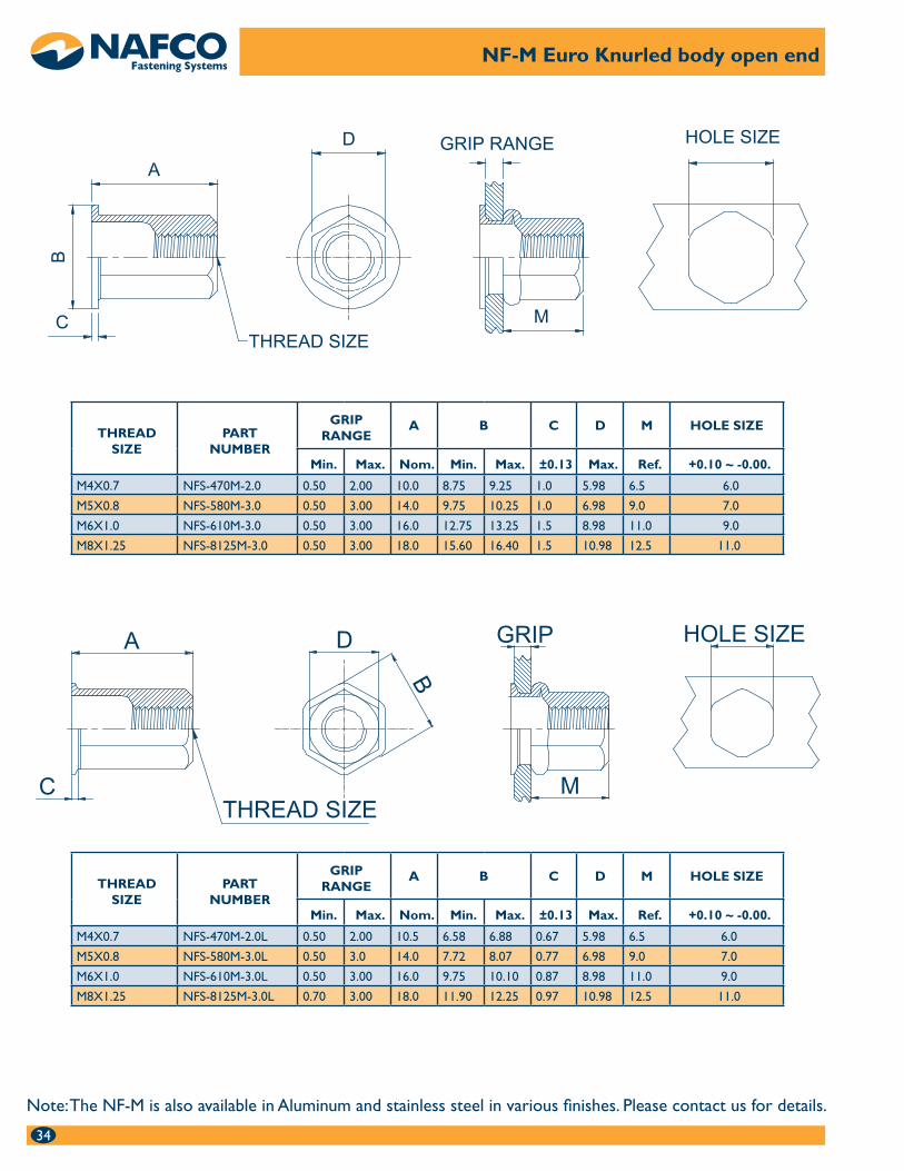
NF-M Euro Knurled body open end
Note: The NF-M is also available in Aluminum and stainless steel in various finishes. Please contact us for details.
THREADSIZE
PART NUMBER
GRIPRANGE
A B C D M HOLE SIZE
Min. Max. Nom. Min. Max. ±0.13 Max. Ref. +0.10 ~ -0.00.
M4X0.7 NFS-470M-2.0 0.50 2.00 10.0 8.75 9.25 1.0 5.98 6.5 6.0
M5X0.8 NFS-580M-3.0 0.50 3.00 14.0 9.75 10.25 1.0 6.98 9.0 7.0
M6X1.0 NFS-610M-3.0 0.50 3.00 16.0 12.75 13.25 1.5 8.98 11.0 9.0
M8X1.25 NFS-8125M-3.0 0.50 3.00 18.0 15.60 16.40 1.5 10.98 12.5 11.0
THREADSIZE
PART NUMBER
GRIPRANGE
A B C D M HOLE SIZE
Min. Max. Nom. Min. Max. ±0.13 Max. Ref. +0.10 ~ -0.00.
M4X0.7 NFS-470M-2.0L 0.50 2.00 10.5 6.58 6.88 0.67 5.98 6.5 6.0
M5X0.8 NFS-580M-3.0L 0.50 3.0 14.0 7.72 8.07 0.77 6.98 9.0 7.0
M6X1.0 NFS-610M-3.0L 0.50 3.00 16.0 9.75 10.10 0.87 8.98 11.0 9.0
M8X1.25 NFS-8125M-3.0L 0.70 3.00 18.0 11.90 12.25 0.97 10.98 12.5 11.0
35
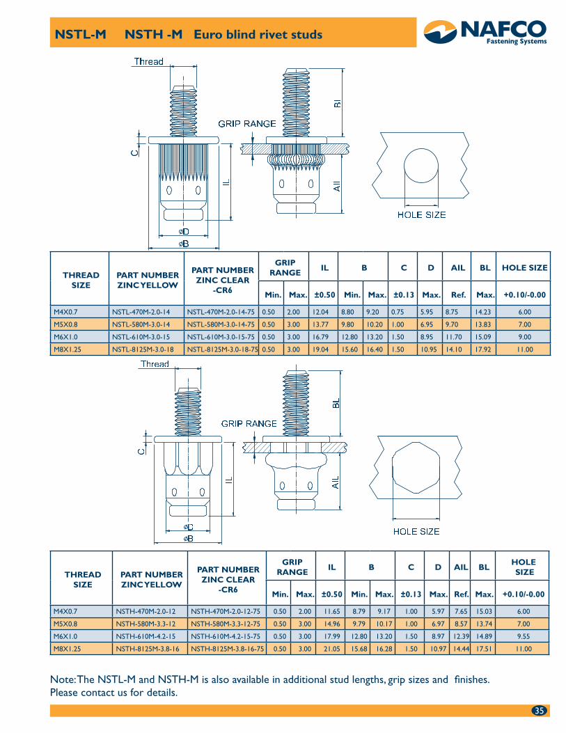
NSTL-M NSTH -M Euro blind rivet studs
Note: The NSTL-M and NSTH-M is also available in additional stud lengths, grip sizes and finishes. Please contact us for details.
THREADSIZE
PART NUMBERZINC YELLOW
PART NUMBERZINC CLEAR
-CR6
GRIPRANGE
IL B C D AIL BL HOLE SIZE
Min. Max. ±0.50 Min. Max. ±0.13 Max. Ref. Max. +0.10/-0.00
M4X0.7 NSTL-470M-2.0-14 NSTL-470M-2.0-14-75 0.50 2.00 12.04 8.80 9.20 0.75 5.95 8.75 14.23 6.00
M5X0.8 NSTL-580M-3.0-14 NSTL-580M-3.0-14-75 0.50 3.00 13.77 9.80 10.20 1.00 6.95 9.70 13.83 7.00
M6X1.0 NSTL-610M-3.0-15 NSTL-610M-3.0-15-75 0.50 3.00 16.79 12.80 13.20 1.50 8.95 11.70 15.09 9.00
M8X1.25 NSTL-8125M-3.0-18 NSTL-8125M-3.0-18-75 0.50 3.00 19.04 15.60 16.40 1.50 10.95 14.10 17.92 11.00
THREADSIZE
PART NUMBERZINC YELLOW
PART NUMBERZINC CLEAR
-CR6
GRIPRANGE
IL B C D AIL BLHOLE SIZE
Min. Max. ±0.50 Min. Max. ±0.13 Max. Ref. Max. +0.10/-0.00
M4X0.7 NSTH-470M-2.0-12 NSTH-470M-2.0-12-75 0.50 2.00 11.65 8.79 9.17 1.00 5.97 7.65 15.03 6.00
M5X0.8 NSTH-580M-3.3-12 NSTH-580M-3.3-12-75 0.50 3.00 14.96 9.79 10.17 1.00 6.97 8.57 13.74 7.00
M6X1.0 NSTH-610M-4.2-15 NSTH-610M-4.2-15-75 0.50 3.00 17.99 12.80 13.20 1.50 8.97 12.39 14.89 9.55
M8X1.25 NSTH-8125M-3.8-16 NSTH-8125M-3.8-16-75 0.50 3.00 21.05 15.68 16.28 1.50 10.97 14.44 17.51 11.00