Embed Size (px)
Citation preview
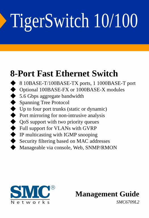
TigerSwitch 10/100
8-Port Fast Ethernet Switch
◆ 8 10BASE-T/100BASE-TX ports, 1 1000BASE-T port◆ Optional 100BASE-FX or 1000BASE-X modules◆ 5.6 Gbps aggregate bandwidth◆ Spanning Tree Protocol◆ Up to four port trunks (static or dynamic)◆ Port mirroring for non-intrusive analysis◆ QoS support with two priority queues◆ Full support for VLANs with GVRP◆ IP multicasting with IGMP snooping◆ Security filtering based on MAC addresses◆ Manageable via console, Web, SNMP/RMONManagement GuideSMC6709L2


38 TeslaIrvine, CA 92618Phone: (949) 679-8000
TigerSwitch 10/100Management Guide
From SMC’s Tiger line of feature-rich workgroup LAN solutions
May 2003Pub. # ?

Information furnished by SMC Networks, Inc. (SMC) is believed to be accurate and reliable. However, no responsibility is assumed by SMC for its use, nor for any infringements of patents or other rights of third parties which may result from its use. No license is granted by implication or otherwise under any patent or patent rights of SMC. SMC reserves the right to change specifications at any time without notice.
Copyright © 2003 by38 Tesla
Irvine, CA 92618All rights reserved. Printed in Taiwan
Trademarks:SMC is a registered trademark; and TigerSwitch is a trademark of SMC Networks, Inc. Other product and company names are trademarks or registered trademarks of their respective holders.
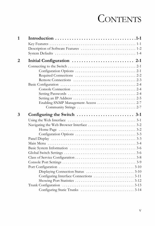
CONTENTS
1 Introduction . . . . . . . . . . . . . . . . . . . . . . . . . . . . . . . . . .1-1Key Features . . . . . . . . . . . . . . . . . . . . . . . . . . . . . . . . . . . . . . . . . . . . . . . 1-1Description of Software Features . . . . . . . . . . . . . . . . . . . . . . . . . . . . . . 1-2System Defaults . . . . . . . . . . . . . . . . . . . . . . . . . . . . . . . . . . . . . . . . . . . . 1-4
2 Initial Configuration . . . . . . . . . . . . . . . . . . . . . . . . . . 2-1Connecting to the Switch . . . . . . . . . . . . . . . . . . . . . . . . . . . . . . . . . . . . . 2-1
Configuration Options . . . . . . . . . . . . . . . . . . . . . . . . . . . . . . . . . 2-1Required Connections . . . . . . . . . . . . . . . . . . . . . . . . . . . . . . . . . 2-2Remote Connections . . . . . . . . . . . . . . . . . . . . . . . . . . . . . . . . . . 2-3
Basic Configuration . . . . . . . . . . . . . . . . . . . . . . . . . . . . . . . . . . . . . . . . . 2-4Console Connection . . . . . . . . . . . . . . . . . . . . . . . . . . . . . . . . . . . 2-4Setting Passwords . . . . . . . . . . . . . . . . . . . . . . . . . . . . . . . . . . . . . 2-4Setting an IP Address . . . . . . . . . . . . . . . . . . . . . . . . . . . . . . . . . . 2-5Enabling SNMP Management Access . . . . . . . . . . . . . . . . . . . . . 2-7
Community Strings . . . . . . . . . . . . . . . . . . . . . . . . . . . . . . . . 2-7
3 Configuring the Switch . . . . . . . . . . . . . . . . . . . . . . . . 3-1Using the Web Interface . . . . . . . . . . . . . . . . . . . . . . . . . . . . . . . . . . . . . 3-1Navigating the Web Browser Interface . . . . . . . . . . . . . . . . . . . . . . . . . . 3-2
Home Page . . . . . . . . . . . . . . . . . . . . . . . . . . . . . . . . . . . . . . . . . . 3-2Configuration Options . . . . . . . . . . . . . . . . . . . . . . . . . . . . . . . . . 3-3
Panel Display . . . . . . . . . . . . . . . . . . . . . . . . . . . . . . . . . . . . . . . . . . . . . . 3-3Main Menu . . . . . . . . . . . . . . . . . . . . . . . . . . . . . . . . . . . . . . . . . . . . . . . . 3-4Basic System Information . . . . . . . . . . . . . . . . . . . . . . . . . . . . . . . . . . . . 3-6Global Switch Settings . . . . . . . . . . . . . . . . . . . . . . . . . . . . . . . . . . . . . . . 3-6Class of Service Configuration . . . . . . . . . . . . . . . . . . . . . . . . . . . . . . . . . 3-8Console Port Settings . . . . . . . . . . . . . . . . . . . . . . . . . . . . . . . . . . . . . . . . 3-9Port Configuration . . . . . . . . . . . . . . . . . . . . . . . . . . . . . . . . . . . . . . . . . 3-10
Displaying Connection Status . . . . . . . . . . . . . . . . . . . . . . . . . . 3-10Configuring Interface Connections . . . . . . . . . . . . . . . . . . . . . . 3-11Showing Port Statistics . . . . . . . . . . . . . . . . . . . . . . . . . . . . . . . . 3-12
Trunk Configuration . . . . . . . . . . . . . . . . . . . . . . . . . . . . . . . . . . . . . . . 3-13Configuring Static Trunks . . . . . . . . . . . . . . . . . . . . . . . . . . . . . 3-14
v
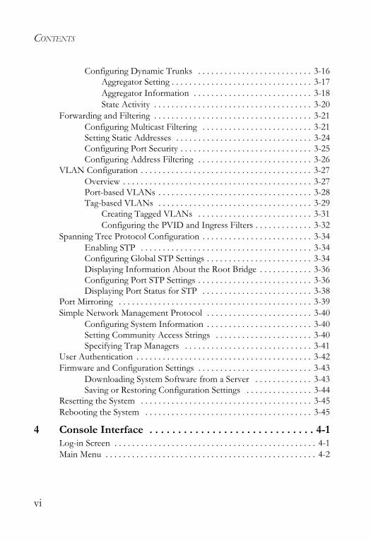
CONTENTS
Configuring Dynamic Trunks . . . . . . . . . . . . . . . . . . . . . . . . . . 3-16Aggregator Setting . . . . . . . . . . . . . . . . . . . . . . . . . . . . . . . . 3-17Aggregator Information . . . . . . . . . . . . . . . . . . . . . . . . . . . 3-18State Activity . . . . . . . . . . . . . . . . . . . . . . . . . . . . . . . . . . . . 3-20
Forwarding and Filtering . . . . . . . . . . . . . . . . . . . . . . . . . . . . . . . . . . . . 3-21Configuring Multicast Filtering . . . . . . . . . . . . . . . . . . . . . . . . . 3-21Setting Static Addresses . . . . . . . . . . . . . . . . . . . . . . . . . . . . . . . 3-24Configuring Port Security . . . . . . . . . . . . . . . . . . . . . . . . . . . . . . 3-25Configuring Address Filtering . . . . . . . . . . . . . . . . . . . . . . . . . . 3-26
VLAN Configuration . . . . . . . . . . . . . . . . . . . . . . . . . . . . . . . . . . . . . . . 3-27Overview . . . . . . . . . . . . . . . . . . . . . . . . . . . . . . . . . . . . . . . . . . . 3-27Port-based VLANs . . . . . . . . . . . . . . . . . . . . . . . . . . . . . . . . . . . 3-28Tag-based VLANs . . . . . . . . . . . . . . . . . . . . . . . . . . . . . . . . . . . 3-29
Creating Tagged VLANs . . . . . . . . . . . . . . . . . . . . . . . . . . 3-31Configuring the PVID and Ingress Filters . . . . . . . . . . . . . 3-32
Spanning Tree Protocol Configuration . . . . . . . . . . . . . . . . . . . . . . . . . 3-34Enabling STP . . . . . . . . . . . . . . . . . . . . . . . . . . . . . . . . . . . . . . . 3-34Configuring Global STP Settings . . . . . . . . . . . . . . . . . . . . . . . . 3-34Displaying Information About the Root Bridge . . . . . . . . . . . . 3-36Configuring Port STP Settings . . . . . . . . . . . . . . . . . . . . . . . . . . 3-36Displaying Port Status for STP . . . . . . . . . . . . . . . . . . . . . . . . . 3-38
Port Mirroring . . . . . . . . . . . . . . . . . . . . . . . . . . . . . . . . . . . . . . . . . . . . 3-39Simple Network Management Protocol . . . . . . . . . . . . . . . . . . . . . . . . 3-40
Configuring System Information . . . . . . . . . . . . . . . . . . . . . . . . 3-40Setting Community Access Strings . . . . . . . . . . . . . . . . . . . . . . 3-40Specifying Trap Managers . . . . . . . . . . . . . . . . . . . . . . . . . . . . . 3-41
User Authentication . . . . . . . . . . . . . . . . . . . . . . . . . . . . . . . . . . . . . . . . 3-42Firmware and Configuration Settings . . . . . . . . . . . . . . . . . . . . . . . . . . 3-43
Downloading System Software from a Server . . . . . . . . . . . . . 3-43Saving or Restoring Configuration Settings . . . . . . . . . . . . . . . 3-44
Resetting the System . . . . . . . . . . . . . . . . . . . . . . . . . . . . . . . . . . . . . . . 3-45Rebooting the System . . . . . . . . . . . . . . . . . . . . . . . . . . . . . . . . . . . . . . 3-45
4 Console Interface . . . . . . . . . . . . . . . . . . . . . . . . . . . . . 4-1Log-in Screen . . . . . . . . . . . . . . . . . . . . . . . . . . . . . . . . . . . . . . . . . . . . . . 4-1Main Menu . . . . . . . . . . . . . . . . . . . . . . . . . . . . . . . . . . . . . . . . . . . . . . . . 4-2
vi
CONTENTS
Status and Counters Menu . . . . . . . . . . . . . . . . . . . . . . . . . . . . . . . . . . . . 4-6Displaying Connection Status . . . . . . . . . . . . . . . . . . . . . . . . . . . 4-7Showing Port Statistics . . . . . . . . . . . . . . . . . . . . . . . . . . . . . . . . . 4-8Displaying System Information . . . . . . . . . . . . . . . . . . . . . . . . . . 4-9
Switch Static Configuration Menu . . . . . . . . . . . . . . . . . . . . . . . . . . . . . 4-10Administration Configuration Menu . . . . . . . . . . . . . . . . . . . . . 4-11
Configuring Device Information . . . . . . . . . . . . . . . . . . . . 4-12Configuring the IP Address . . . . . . . . . . . . . . . . . . . . . . . . 4-13Configuring the User Name . . . . . . . . . . . . . . . . . . . . . . . . 4-14Configuring the Password . . . . . . . . . . . . . . . . . . . . . . . . . 4-15
Configuring Interface Connections . . . . . . . . . . . . . . . . . . . . . . 4-16Configuring Port Mirroring . . . . . . . . . . . . . . . . . . . . . . . . . . . . 4-18VLAN Configuration Menu . . . . . . . . . . . . . . . . . . . . . . . . . . . . 4-20
Configuring Port-based VLANs . . . . . . . . . . . . . . . . . . . . 4-21Configuring Tag-based VLANs . . . . . . . . . . . . . . . . . . . . . 4-22
Configuring Queue Priorities . . . . . . . . . . . . . . . . . . . . . . . . . . . 4-24MAC Address Configuration Menu . . . . . . . . . . . . . . . . . . . . . . 4-26
Setting Static Addresses . . . . . . . . . . . . . . . . . . . . . . . . . . . 4-26Configuring Address Filtering . . . . . . . . . . . . . . . . . . . . . . 4-28
Miscellaneous Configuration Menu . . . . . . . . . . . . . . . . . . . . . . 4-29Configuring Port Security . . . . . . . . . . . . . . . . . . . . . . . . . . 4-30Configuring Address Aging . . . . . . . . . . . . . . . . . . . . . . . . 4-31Configuring Broadcast Storm Control . . . . . . . . . . . . . . . . 4-32Configuring the Transmit Delay Bound . . . . . . . . . . . . . . 4-33
Protocol Related Configuration Menu . . . . . . . . . . . . . . . . . . . . . . . . . 4-34Spanning Tree Protocol Menu . . . . . . . . . . . . . . . . . . . . . . . . . . 4-35
Enabling STP . . . . . . . . . . . . . . . . . . . . . . . . . . . . . . . . . . . 4-36Displaying Information About the Root Bridge . . . . . . . . 4-36Configuring Global STP Settings . . . . . . . . . . . . . . . . . . . . 4-38Configuring Port STP Settings . . . . . . . . . . . . . . . . . . . . . . 4-40
Simple Network Management Protocol Menu . . . . . . . . . . . . . 4-42Configuring System Information . . . . . . . . . . . . . . . . . . . . 4-43Setting Community Access Strings . . . . . . . . . . . . . . . . . . 4-44Specifying Trap Managers . . . . . . . . . . . . . . . . . . . . . . . . . 4-45
GVRP Configuration . . . . . . . . . . . . . . . . . . . . . . . . . . . . . . . . . 4-46
vii
CONTENTS
Link Access Control Protocol Menu . . . . . . . . . . . . . . . . . . . . . 4-47Configuring the Aggregator Setting . . . . . . . . . . . . . . . . . . 4-48Setting the State Activity . . . . . . . . . . . . . . . . . . . . . . . . . . . 4-49Displaying Aggregator Information . . . . . . . . . . . . . . . . . . 4-50
Reboot Switch Menu . . . . . . . . . . . . . . . . . . . . . . . . . . . . . . . . . . . . . . 4-52Set Logout Timer Menu . . . . . . . . . . . . . . . . . . . . . . . . . . . . . . . . . . . . . 4-53
5 Command Line Interface . . . . . . . . . . . . . . . . . . . . . . 5-1Accessing the CLI . . . . . . . . . . . . . . . . . . . . . . . . . . . . . . . . . . . . . . . . . . 5-1Entering Commands . . . . . . . . . . . . . . . . . . . . . . . . . . . . . . . . . . . . . . . . 5-1
Keywords and Arguments . . . . . . . . . . . . . . . . . . . . . . . . . . . . . . 5-1Minimum Abbreviation . . . . . . . . . . . . . . . . . . . . . . . . . . . . . . . . 5-2Getting Help on Commands . . . . . . . . . . . . . . . . . . . . . . . . . . . . 5-2
Command Groups . . . . . . . . . . . . . . . . . . . . . . . . . . . . . . . . . . . . . . . . . . 5-3System Configuration (advance) . . . . . . . . . . . . . . . . . . . . . . . . . . . . . . . 5-4Port Configuration (port) . . . . . . . . . . . . . . . . . . . . . . . . . . . . . . . . . . . . . 5-5VLAN Configuration (vlan) . . . . . . . . . . . . . . . . . . . . . . . . . . . . . . . . . . 5-6
Supported Protocols . . . . . . . . . . . . . . . . . . . . . . . . . . . . . . . . . . . 5-7Filter Database Configuration (fdb) . . . . . . . . . . . . . . . . . . . . . . . . . . . . 5-8Trunk Configuration (trkgrp) . . . . . . . . . . . . . . . . . . . . . . . . . . . . . . . . . 5-9Spanning Tree Protocol Configuration (stp) . . . . . . . . . . . . . . . . . . . . 5-10Quality of Service Configuration (qos) . . . . . . . . . . . . . . . . . . . . . . . . . 5-11IGMP Snooping Configuration (igmp) . . . . . . . . . . . . . . . . . . . . . . . . . 5-11Console Configuration (console) . . . . . . . . . . . . . . . . . . . . . . . . . . . . . . 5-12
A Software Specifications . . . . . . . . . . . . . . . . . . . . . . . . .A-1Switch Features . . . . . . . . . . . . . . . . . . . . . . . . . . . . . . . . . . . . . . . . . . . . A-1Management Features . . . . . . . . . . . . . . . . . . . . . . . . . . . . . . . . . . . . . . . A-2Standards . . . . . . . . . . . . . . . . . . . . . . . . . . . . . . . . . . . . . . . . . . . . . . . . . A-2
B Upgrading Firmware . . . . . . . . . . . . . . . . . . . . . . . . . .B-1C Troubleshooting . . . . . . . . . . . . . . . . . . . . . . . . . . . . . .C-1
Glossary
Index
viii
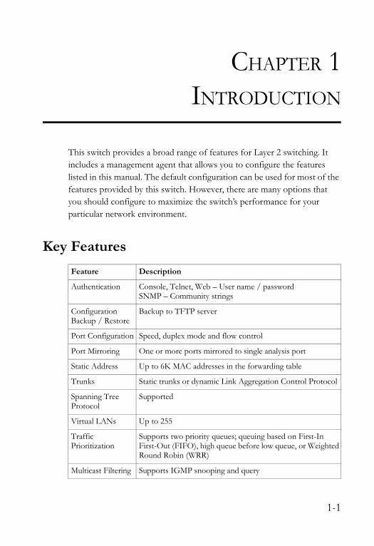
CHAPTER 1INTRODUCTION
This switch provides a broad range of features for Layer 2 switching. It includes a management agent that allows you to configure the features listed in this manual. The default configuration can be used for most of the features provided by this switch. However, there are many options that you should configure to maximize the switch’s performance for your particular network environment.
Key FeaturesFeature Description
Authentication Console, Telnet, Web – User name / passwordSNMP – Community strings
Configuration Backup / Restore
Backup to TFTP server
Port Configuration Speed, duplex mode and flow control
Port Mirroring One or more ports mirrored to single analysis port
Static Address Up to 6K MAC addresses in the forwarding table
Trunks Static trunks or dynamic Link Aggregation Control Protocol
Spanning Tree Protocol
Supported
Virtual LANs Up to 255
Traffic Prioritization
Supports two priority queues; queuing based on First-In First-Out (FIFO), high queue before low queue, or Weighted Round Robin (WRR)
Multicast Filtering Supports IGMP snooping and query
1-1
INTRODUCTION
Description of Software FeaturesIEEE 802.1D Bridge – The switch supports IEEE 802.1D transparent bridging. The address table facilitates data switching by learning addresses, and then filtering or forwarding traffic based on this information. The address table supports up to 6K addresses.
Store-and-Forward Switching – The switch copies each frame into its memory before forwarding them to another port. This ensures that all frames are a standard Ethernet size and have been verified for accuracy with the cyclic redundancy check (CRC). This prevents bad frames from entering the network and wasting bandwidth.
To avoid dropping frames on congested ports, the switch provides 8? MB for frame buffering. This buffer can queue packets awaiting transmission on congested networks.
Spanning Tree Protocol – The switch supports IEEE 802.1D Spanning Tree Protocol. This protocol adds a level of fault tolerance by allowing two or more redundant connections to be created between a pair of LAN segments. When there are multiple physical paths between segments, the protocol will choose a single path and disable all others to ensure that only one route exists between any two stations on the network. This prevents the creation of network loops. However, if the chosen path should fail for any reason, an alternate path will be activated to maintain the connection.
VLANs – This switch supports up to 255 VLANs. A Virtual LAN is a collection of network nodes that share the same collision domain regardless of their physical location or connection point in the network. By segmenting your network into VLANs, you can:
• Eliminate broadcast storms which severely degrade performance in a flat network.
1-2
DESCRIPTION OF SOFTWARE FEATURES
• Simplify network management for node changes/moves by remotely configuring VLAN membership for any port, rather than having to manually change the network connection.
• Provide data security by restricting all traffic to the originating VLAN.
Port Mirroring – The switch can unobtrusively mirror traffic from any port to a monitor port. You can then attach a protocol analyzer or RMON probe to this port to perform traffic analysis and verify connection integrity.
Port Trunking – Ports can be combined into an aggregate connection. Trunks can be manually set up or dynamically configured using IEEE 802.3ad Link Aggregation Control Protocol (LACP). The additional ports dramatically increase the throughput across any connection, and provide redundancy by taking over the load if a port in the trunk should fail. The switch supports four trunks, with up to eight up-link ports per trunk.
Broadcast Suppression – Broadcast suppression prevents broadcast traffic from overwhelming the network. When enabled on a port, the level of broadcast traffic passing through the port is restricted. If broadcast traffic rises above a pre-defined threshold, it will be throttled until the level falls back beneath the threshold.
Flow Control – Flow control reduces traffic during periods of congestion and prevent packets from being dropped when port buffers overflow. The switch supports flow control based on the IEEE 802.3x standard. By default, flow control is enabled on all ports.
Traffic Priority – This switch provides Quality of Service (QoS) by prioritizing each packet based on the required level of service, using two priority queues, and processing the high-priority queue before the low- priority queue, or using Weighted Round Robin Queuing (WRR). It uses IEEE 802.1p and 802.1Q tags to prioritize incoming traffic based on input from the end-station application. These functions can be used to provide independent priorities for delay-sensitive data and best-effort data.
1-3
INTRODUCTION
Multicast Filtering – Specific multicast traffic can be assigned to its own VLAN to ensure that it does not interfere with normal network traffic and to guarantee real-time delivery by setting the required priority level for the designated VLAN. The switch uses IGMP Snooping and Query to manage multicast group registration.
System DefaultsThe following table lists some of the basic system defaults.
Function Parameter Default
IP Settings IP Address 0.0.0.0
Subnet Mask 0.0.0.0
Default Gateway 0.0.0.0
SNMP Community Strings “public” (read only)
Traps Authentication traps ? Link-up-down events ?
Security Console, Telnet, Web Username “admin”Password “admin”
Address Learning Enabled (all ports)
Console Port Connection
Baud Rate 9600
Data bits 8
Stop bits 1
Parity none
Local Console Timeout 1 minute
Port Status Admin Status Enabled
Auto-negotiation Enabled
Flow Control Enabled
Link Aggregation
Static Trunks None
LACP (all ports) Disabled
1-4
SYSTEM DEFAULTS
Note: To reset the switch defaults, use the Reset System command (page 3-45).
Spanning Tree Protocol
Status Enabled(Defaults: All values based on IEEE 802.1D)
Address Table Aging Time 300 seconds
Forwarding and Filtering Static addresses: noneFilter addresses: none
Multicast Filtering
IGMP Snooping Disabled
IGMP Query Auto-negotiation
Virtual LANs VLAN Status Disabled
Default VLAN 1
PVID 1
Ingress Filtering (Rule 1)- Tag must match PVID
Enabled
Ingress Filtering (Rule 2)- Acceptable frame types
All
GVRP Disabled
Class of Service Weighted Round Robin Weight: 2 high, 1 lowQueues: 7-4 high, 3-0 low
Broadcast Storm Protection
Status Disabled (all ports)
Function Parameter Default
1-5

INTRODUCTION
1-6
CHAPTER 2INITIAL CONFIGURATION
Connecting to the Switch
Configuration OptionsThe switch includes a built-in network management agent. The agent offers a variety of management options, including SNMP, RMON, and a Web-based interface. A PC may also be connected directly to the switch for configuration and monitoring via the console menu.
Note: The IP address for this switch is unassigned by default. To change this address, see “Setting an IP Address” on page 2-5.
The switch’s HTTP Web agent allows you to configure switch parameters, monitor port connections, and display statistics using a standard Web browser such as Netscape Navigator version 6.2 and higher or Microsoft IE version 5.0 and higher. The switch’s Web management interface can be accessed from any computer attached to the network.
The switch’s management agent is based on SNMP (Simple Network Management Protocol). This SNMP agent permits the switch to be managed from any system in the network using management software, such as SMC’s free EliteView software.
The console menu can be accessed by a direct connection to the RS-232 serial console port on the switch, or remotely by a Telnet connection over the network.
2-1
INITIAL CONFIGURATION
The switch’s console menu, Web Interface, and SNMP agent allow you to perform the following management functions:
• Set user name and password • Set an IP interface for management access (console menu only)• Configure SNMP parameters • Enable/disable any Ethernet port• Set the speed/duplex mode for any port • Configure up to 255 IEEE 802.1Q VLANs • Enable GVRP automatic VLAN registration• Configure IGMP multicast filtering• Upload and download system firmware via TFTP• Upload and download switch configuration files via TFTP• Configure Spanning Tree parameters• Configure Class of Service (CoS) priority queuing• Configure up to four static or LACP trunks• Enable port mirroring• Prevent broadcast storms by limiting bandwidth for broadcast traffic• Display system information and statistics
Required Connections The switch provides an RS-232 serial port that enables a connection to a PC or terminal for monitoring and configuring the switch. A null-modem console cable is provided with the switch.
Attach a VT100-compatible terminal, or a PC running a terminal emulation program to the switch. You can use the console cable provided with this package, or use a null-modem cable that complies with the wiring assignments shown in the Installation Guide.
To connect a terminal to the console port, complete the following steps:
1. Connect the console cable to the serial port on a terminal, or a PC running terminal emulation software, and tighten the captive retaining screws on the DB-9 connector.
2-2
CONNECTING TO THE SWITCH
2. Connect the other end of the cable to the RS-232 serial port on the switch.
3. Make sure the terminal emulation software is set as follows:
• Select the appropriate serial port (COM port 1 or COM port 2). • Set the data rate to 9600 baud. • Set the data format to 8 data bits, 1 stop bit, and no parity. • Set flow control to none. • Set the emulation mode to VT100.
Note: Once you have set up the terminal correctly, the console login screen will be displayed.
Remote ConnectionsPrior to accessing the switch’s onboard agent via a network connection, you must first configure it with a valid IP address, subnet mask, and default gateway using a console connection.
The IP address for this switch is unassigned by default. To manually configure this address to one that matches your specific network requirements, see “Setting an IP Address” on page 2-5.
After configuring the switch’s IP parameters, you can access the onboard configuration program from anywhere within the attached network. The onboard configuration program can be accessed using Telnet from any computer attached to the network. The switch can also be managed by any computer using a Web browser (Internet Explorer 5.0 or above, or Netscape Navigator 6.2 or above), or from a network computer using network management software such as EliteView.
Notes: 1. Only one management session is supported.
2. The onboard program only provides access to basic configuration functions. To access the full range of SNMP management functions, you must use SNMP-based network management software, such as EliteView.
2-3
INITIAL CONFIGURATION
Basic Configuration
Console ConnectionAccess to the console menu is controlled by a user name and password. The default setting is “admin” for both the user name and password. To log into the console menu, perform these steps:
1. Enter “admin” at the user name prompt.
2. Enter “admin” at the password prompt. (The password characters are not displayed on the console screen.)
The session is opened and the Main Menu displays.
Setting PasswordsNote: If this is your first time to log into the CLI program, you should
define a new user name and password, record them and put them in a safe place.
A user name or password can consist of up to 15 alphanumeric characters and are not case sensitive. To prevent unauthorized access to the switch, set the user name and password as follows:
1. Open the console interface with the default user name and password “admin” to access the Main Menu.
2. Navigate from the Main Menu to –Switch Static Configuration, and thenAdministration Configuration.
3. Select “Change Username” and press <Enter>.• Select <Edit>, type in the new user name, and press <Enter>.• Select <Save> and press Enter.
2-4
BASIC CONFIGURATION
4. Select “Change Password” and press <Enter>.• Type the old password and press <Enter>.• Type the new password and press <Enter>.• Then re-enter the new password for verification, press <Enter>.
Setting an IP AddressYou must establish IP address information for the switch to obtain management access through the network. You can manually assign an IP address to the switch. You may also need to specify a default gateway that resides between this device and management stations that exist on another network segment. Valid IP addresses consist of four decimal numbers, 0 to 255, separated by periods. Anything outside this format will not be accepted by the configuration program.
Note: The IP address for this switch is unassigned by default.
Before you can assign an IP address to the switch, you must obtain the following information from your network administrator:
• IP address for the switch • Network mask for this network • Default gateway for the network
2-5
INITIAL CONFIGURATION
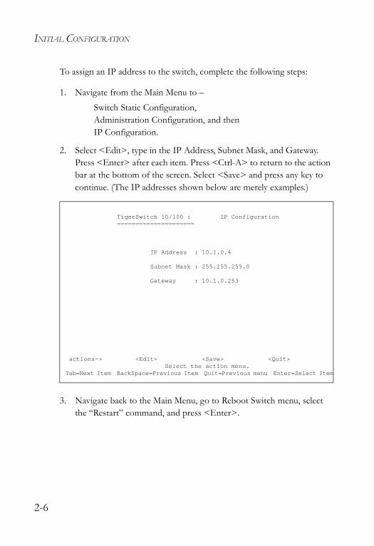
To assign an IP address to the switch, complete the following steps:
1. Navigate from the Main Menu to –Switch Static Configuration, Administration Configuration, and thenIP Configuration.
2. Select <Edit>, type in the IP Address, Subnet Mask, and Gateway. Press <Enter> after each item. Press <Ctrl-A> to return to the action bar at the bottom of the screen. Select <Save> and press any key to continue. (The IP addresses shown below are merely examples.)
3. Navigate back to the Main Menu, go to Reboot Switch menu, select the “Restart” command, and press <Enter>.
TigerSwitch 10/100 : IP Configuration=====================
IP Address : 10.1.0.4
Subnet Mask : 255.255.255.0
Gateway : 10.1.0.253
actions-> <Edit> <Save> <Quit>Select the action menu.
Tab=Next Item BackSpace=Previous Item Quit=Previous menu Enter=Select Item
2-6
BASIC CONFIGURATION
Enabling SNMP Management Access The switch can be configured to accept management commands from Simple Network Management Protocol (SNMP) applications such as SMC’s EliteView. You also can configure the switch to generate SNMP traps.
When SNMP management stations send requests to the switch (either to return information or to set a parameter), the switch provides the requested data or sets the specified parameter. The switch can also be configured to send information to SNMP managers (without being requested by the managers) through trap messages that inform the manager that certain events have occurred.
Community StringsCommunity strings are used to control management access to SNMP stations, as well as to authorize SNMP stations to receive trap messages from the switch. You therefore need to assign community strings to specified users or user groups, and set the access level.
The default string is “public” with read-only access. Authorized management stations are only able to retrieve MIB objects.
Note: If you do not intend to use SNMP, it is recommended that you delete all community strings. If there are no community strings, then SNMP management access to the switch is disabled.
To configure a community string, complete the following steps:
1. Navigate from the Main Menu to –Protocol Related Configuration, SNMP, and thenCommunity Strings.
2. Click <Add>, then <Edit>.
3. Type in the Community Name, and press <Enter>.
2-7

INITIAL CONFIGURATION
4. Use the scroll-bar to toggle the Write Access Field to “Restricted” or “Unrestricted.”
5. Press <Ctrl-A> to return to the action bar at the bottom of the screen. Select <Save> and press any key to continue. (The community string shown below is an example.)
TigerSwitch 10/100 : Add SNMP Community=====================
Community Name :private
Write Access :Unrestricted
actions-> <Edit> <Save> <Quit>Select the action menu.
Tab=Next Item BackSpace=Previous Item Space=Toggle Ctrl+A=Action menu
2-8
CHAPTER 3CONFIGURING THE SWITCH
Using the Web InterfaceThis switch provides an embedded HTTP Web agent. Using a Web browser you can configure the switch and view statistics to monitor network activity. The Web agent can be accessed by any computer on the network using a standard Web browser (Internet Explorer 5.0 or above, or Netscape Navigator 6.2 or above.)
Note: You can also use the console menu to manage the switch over a serial connection to the console port or via Telnet. For more information on using the console menu, refer to Chapter 4, “Console Interface.”
Prior to accessing the switch from a Web browser, be sure you have first performed the following tasks:
1. Configure the switch with a valid IP address, subnet mask, and default gateway using an out-of-band serial connection. (See “Setting an IP Address” on page 2-5.)
2. Set a user name and password. Access to the Web agent is controlled by the same user name and password as the console configuration program. (See “Setting Passwords” on page 2-4.)
3. After you enter a user name and password, you will have access to the system configuration program.
Note: You are allowed three attempts to enter the correct password; on the third failed attempt the current connection is terminated.
3-1
CONFIGURING THE SWITCH
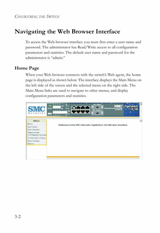
Navigating the Web Browser InterfaceTo access the Web-browser interface you must first enter a user name and password. The administrator has Read/Write access to all configuration parameters and statistics. The default user name and password for the administrator is “admin.”
Home PageWhen your Web browser connects with the switch’s Web agent, the home page is displayed as shown below. The interface displays the Main Menu on the left side of the screen and the selected menu on the right side. The Main Menu links are used to navigate to other menus, and display configuration parameters and statistics.
3-2
PANEL DISPLAY
Configuration OptionsConfigurable parameters have a dialog box or a drop-down list. Once a configuration change has been made on a page, be sure to click on the “Apply” button to confirm the new setting. The following table summarizes the Web page configuration buttons.
Notes: 1. To ensure proper screen refresh, be sure that Internet Explorer 5.x is configured as follows: Under the menu “Tools / Internet Options / General / Temporary Internet Files / Settings,” the setting for item “Check for newer versions of stored pages” should be “Every visit to the page.”
2. When using Internet Explorer 5.0, you may have to manually refresh the screen after making configuration changes by pressing the browser’s refresh button.
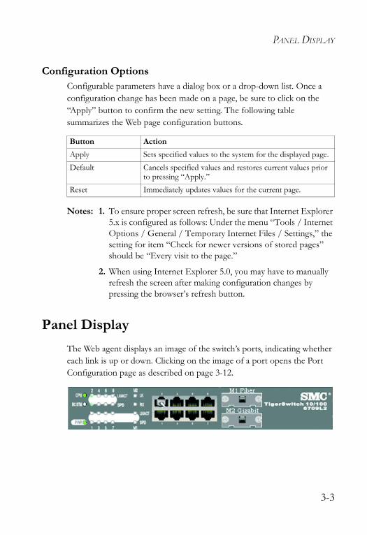
Panel DisplayThe Web agent displays an image of the switch’s ports, indicating whether each link is up or down. Clicking on the image of a port opens the Port Configuration page as described on page 3-12.
Button ActionApply Sets specified values to the system for the displayed page. Default Cancels specified values and restores current values prior
to pressing “Apply.”Reset Immediately updates values for the current page.
3-3
CONFIGURING THE SWITCH
Main Menu Using the onboard Web agent, you can define system parameters, manage and control the switch, or monitor network conditions. The following table briefly describes the selections available from this program.
Menu Description PageHome Main Menu 3-2Port Status Displays port connection status 3-10Port Statistics Lists Ethernet statistics 3-12Administrator
Switch SettingsBasic Shows system model number, MAC address,
hardware version, and firmware version3-6
Advanced Provides settings for address aging time, maximum queue delay, broadcast storm control, priority queue options, and global settings for STP, IGMP, and VLANs
3-6
Console Port Info Displays settings for the console port 3-9Port Controls 3-10
Port Controls Configures connection settings including speed, duplex mode, and flow control
3-11
Port Status Displays the current connection settings 3-10Trunking
Aggregator Setting Configures static or dynamic trunks 3-17Aggregator Information
Shows trunks and associated ports, and detailed information for dynamic links
3-18
State Activity Actively or passively configures a trunk 3-20Filter Database
IGMP Snooping Displays active multicast groups, VLAN identifier, and associated ports
3-21
Static MAC Addresses
Sets entries for address, port number, and VLAN identifier
3-24
Port Security Enables and disables address learning 3-25MAC Filtering Filters specified addresses 3-26
3-4
MAIN MENU
VLAN Configuration 3-27Basic Configures VLAN groups, including name,
identifier, and if limited to a specific protocol 3-283-29
Port VID Sets port VID and ingress filters 3-32Spanning Tree Configures global bridge and port settings
for STP; also displays current port status3-34
Port Sniffer Sets the source and target ports for mirroring 3-39SNMP 3-40
System Options Provides basic system description, including contact information
3-40
Community Strings Configures community strings 3-40Trap Managers Sets trap management stations 3-41
Security Manager Assigns a user name and password 3-42TFTP Update Firmware Downloads a new code image 3-43Configuration Backup 3-44
TFTP Restore Configuration
Restores configuration settings 3-44
TFTP Backup Configuration
Backs up configuration settings 3-44
Reset System Resets switch to the default configuration 3-45Reboot Reboots the switch 3-45
Menu Description Page
3-5
CONFIGURING THE SWITCH
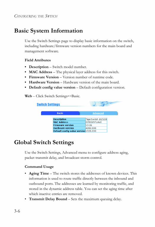
Basic System InformationUse the Switch Settings page to display basic information on the switch, including hardware/firmware version numbers for the main board and management software.
Field Attributes
• Description – Switch model number.• MAC Address – The physical layer address for this switch. • Firmware Version – Version number of runtime code.• Hardware Version – Hardware version of the main board.• Default config value version – Default configuration version.
Web – Click Switch Settings=>Basic.
Global Switch SettingsUse the Switch Settings, Advanced menu to configure address aging, packet transmit delay, and broadcast storm control.
Command Usage
• Aging Time – The switch stores the addresses of known devices. This information is used to route traffic directly between the inbound and outbound ports. The addresses are learned by monitoring traffic, and stored in the dynamic address table. You can set the aging time after which inactive entries are removed.
• Transmit Delay Bound – Sets the maximum queuing delay.
3-6
GLOBAL SWITCH SETTINGS
• Broadcast Storm Control – Broadcast storms may occur when a device on your network is malfunctioning, or if application programs are not well designed or properly configured. If there is too much broadcast traffic on your network, performance can be severely degraded or everything can come to a complete halt. You can protect your network from broadcast storms by setting a maximum threshold for broadcast traffic.
Field Attributes
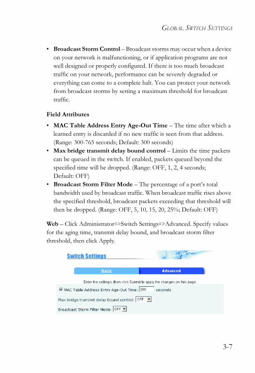
• MAC Table Address Entry Age-Out Time – The time after which a learned entry is discarded if no new traffic is seen from that address. (Range: 300-765 seconds; Default: 300 seconds)
• Max bridge transmit delay bound control – Limits the time packets can be queued in the switch. If enabled, packets queued beyond the specified time will be dropped. (Range: OFF, 1, 2, 4 seconds; Default: OFF)
• Broadcast Storm Filter Mode – The percentage of a port’s total bandwidth used by broadcast traffic. When broadcast traffic rises above the specified threshold, broadcast packets exceeding that threshold will then be dropped. (Range: OFF, 5, 10, 15, 20, 25%; Default: OFF)
Web – Click Administrator=>Switch Settings=>Advanced. Specify values for the aging time, transmit delay bound, and broadcast storm filter threshold, then click Apply.
3-7
CONFIGURING THE SWITCH
Class of Service ConfigurationClass of Service (CoS) allows you to specify which data packets have greater precedence when traffic is buffered in the switch due to congestion. This switch supports CoS with two priority queues for each port. Data packets in a port’s high-priority queue are transmitted before those in the lower-priority queue.
You can set the method used to process priority traffic (i.e., first-in first-out, all high before low, or weighted round-robin), and also map the frame priority tags (i.e., 0 - 7) to the high or low priority queues.
Field Attributes
• First Come First Served – Packets are processed first-in first-out. • All High before Low – All packets in the high-priority queue are
processed before any packets in the low-priority queue.• Weighted Round Robin – Sets the preference given to packets in the
high-priority queue. This specifies the number of high-priority packets sent before one low-priority packet is sent. (Range: 1-7; Default: 2)
• Enable Delay Bound – Limits the queuing time for low-priority packets. Any low-priority packets that exceed the delay bound will be sent. Note that the “Max bridge transmit delay bound control” must be enabled (page 3-6) for the Enable Delay Bound to function. (Range: 0-255 ms; Default: 0 ms)
• QoS Policy (High Priority Levels) – The default priority levels are assigned according to recommendations in the IEEE 802.1p standard. However, you can map the priority levels to the switch’s output queues in any way that benefits application traffic for your own network. (Range: Level 0 - 7; Default: Level 4 - 7)
Web – Click Administrator=>Switch Settings=>Advanced. Select the priority method (First Come First Serve, All High before Low, or WRR), set the high-priority queue weight preference when using WRR, set a delay
3-8
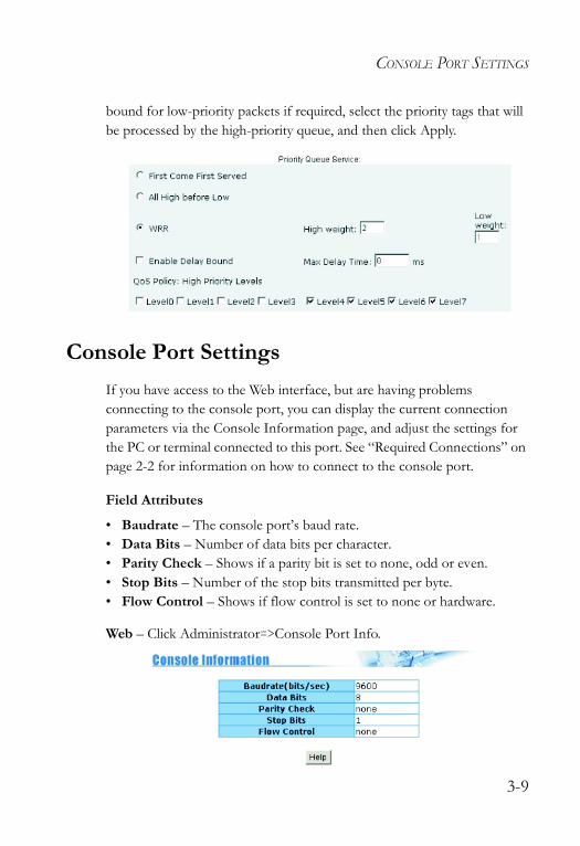
CONSOLE PORT SETTINGS
bound for low-priority packets if required, select the priority tags that will be processed by the high-priority queue, and then click Apply.
Console Port SettingsIf you have access to the Web interface, but are having problems connecting to the console port, you can display the current connection parameters via the Console Information page, and adjust the settings for the PC or terminal connected to this port. See “Required Connections” on page 2-2 for information on how to connect to the console port.
Field Attributes
• Baudrate – The console port’s baud rate.• Data Bits – Number of data bits per character. • Parity Check – Shows if a parity bit is set to none, odd or even.• Stop Bits – Number of the stop bits transmitted per byte.• Flow Control – Shows if flow control is set to none or hardware.
Web – Click Administrator=>Console Port Info.
3-9
CONFIGURING THE SWITCH
Port Configuration
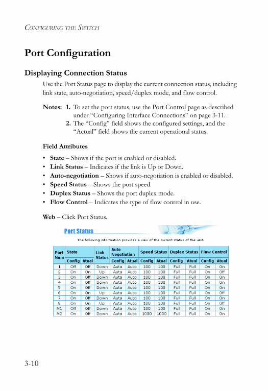
Displaying Connection StatusUse the Port Status page to display the current connection status, including link state, auto-negotiation, speed/duplex mode, and flow control.
Notes: 1. To set the port status, use the Port Control page as described under “Configuring Interface Connections” on page 3-11.
2. The “Config” field shows the configured settings, and the “Actual” field shows the current operational status.
Field Attributes
• State – Shows if the port is enabled or disabled. • Link Status – Indicates if the link is Up or Down. • Auto-negotiation – Shows if auto-negotiation is enabled or disabled.• Speed Status – Shows the port speed.• Duplex Status – Shows the port duplex mode.• Flow Control – Indicates the type of flow control in use.
Web – Click Port Status.
3-10
PORT CONFIGURATION
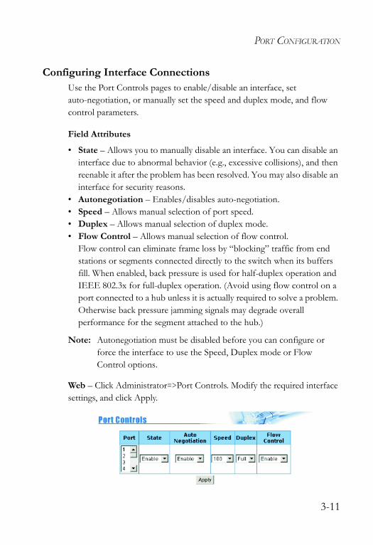
Configuring Interface ConnectionsUse the Port Controls pages to enable/disable an interface, set auto-negotiation, or manually set the speed and duplex mode, and flow control parameters.
Field Attributes
• State – Allows you to manually disable an interface. You can disable an interface due to abnormal behavior (e.g., excessive collisions), and then reenable it after the problem has been resolved. You may also disable an interface for security reasons.
• Autonegotiation – Enables/disables auto-negotiation. • Speed – Allows manual selection of port speed.• Duplex – Allows manual selection of duplex mode.• Flow Control – Allows manual selection of flow control.
Flow control can eliminate frame loss by “blocking” traffic from end stations or segments connected directly to the switch when its buffers fill. When enabled, back pressure is used for half-duplex operation and IEEE 802.3x for full-duplex operation. (Avoid using flow control on a port connected to a hub unless it is actually required to solve a problem. Otherwise back pressure jamming signals may degrade overall performance for the segment attached to the hub.)
Note: Autonegotiation must be disabled before you can configure or force the interface to use the Speed, Duplex mode or Flow Control options.
Web – Click Administrator=>Port Controls. Modify the required interface settings, and click Apply.
3-11
CONFIGURING THE SWITCH
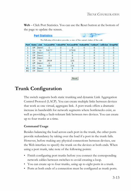
Showing Port StatisticsYou can display standard statistics on network traffic from the Interfaces Group MIB, Ethernet-like MIB, and RMOM MIB. These statistics display errors on the traffic passing through each port. This information can be used to identify potential problems with the switch (such as a faulty port or unusually heavy loading). All values displayed have been accumulated since the last system reboot, and are shown as counts per second. Statistics are refreshed every 5 seconds.
Note: RMON groups 2, 3 and 9 can only be accessed using SNMP management software.
Field Attributes
• State – Shows whether or not the port is operational.• Link – Indicates if the link is Up or Down. • TxGoodPkt – The total number of packets transmitted out of the
interface, including framing characters.• TxBadPkt – The number of outbound packets that could not be
transmitted because of errors.• RxGoodPkt – The total number of packets received on the interface,
including framing characters.• RxBadPkt – The number of inbound packets that contained errors
preventing them from being delivered to a higher-layer protocol.• TxAbort – The number of outbound packets which were chosen to be
discarded even though no errors had been detected to prevent their being transmitted. One possible reason for discarding such a packet could be to free up buffer space.
• Collision – The best estimate of the total number of collisions on this Ethernet segment.
• DropPkt – The total number of events in which packets were dropped due to lack of resources.
3-12
TRUNK CONFIGURATION
Web – Click Port Statistics. You can use the Reset button at the bottom of the page to update the screen.
Trunk ConfigurationThe switch supports both static trunking and dynamic Link Aggregation Control Protocol (LACP). You can create multiple links between devices that work as one virtual, aggregate link. A port trunk offers a dramatic increase in bandwidth for network segments where bottlenecks exist, as well as providing a fault-tolerant link between two devices. You can create up to four trunks at a time.
Command Usage
Besides balancing the load across each port in the trunk, the other ports provide redundancy by taking over the load if a port in the trunk fails. However, before making any physical connections between devices, use the Web interface to specify the trunk on the devices at both ends. When using a port trunk, take note of the following points:
• Finish configuring port trunks before you connect the corresponding network cables between switches to avoid creating a loop.
• You can create up to four trunks, using up to eight ports in a trunk.• Ports at both ends of a connection must be configured as trunk ports.
3-13
CONFIGURING THE SWITCH
• The ports at both ends of a trunk must be configured in an identical manner, including communication mode (i.e., speed, duplex mode and flow control), VLAN assignments, and CoS settings.
• All the ports in a trunk have to be treated as a whole when moved from/to, added or deleted from a VLAN.
• The same STP, VLAN, and IGMP settings must be configured for all the ports in a trunk.
Configuring Static TrunksYou can manually assign specific ports to a static trunk.
Command Usage
• To avoid creating a loop in the network, be sure that you add a static trunk via the Web interface before connecting the ports, and also disconnect ports before removing a static trunk via the Web interface.
• When using static trunks, you may not be able to link to switches of different types, depending on the manufacturer’s implementation.
Field Attributes
Aggregator Setting page
• System Priority – Not applicable for static trunks.• Group ID – Specifies the static trunk group. (Range: 1-4)• LACP – Set this field to “Disable” when configuring a static trunk.• Work Ports – Assigns port members to the static trunk. (Range: 1-8)
Aggregator Information page
• Group Key – Displays active static trunks.• Port No – Shows the port members assigned to each static trunk.
3-14
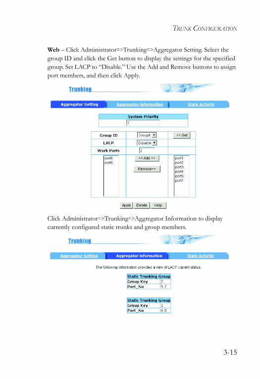
TRUNK CONFIGURATION
Web – Click Administrator=>Trunking=>Aggregator Setting. Select the group ID and click the Get button to display the settings for the specified group. Set LACP to “Disable.” Use the Add and Remove buttons to assign port members, and then click Apply.
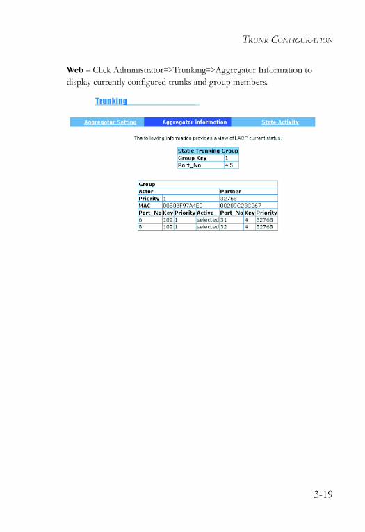
Click Administrator=>Trunking=>Aggregator Information to display currently configured static trunks and group members.
3-15
CONFIGURING THE SWITCH
Configuring Dynamic TrunksPorts configured for LACP can automatically negotiate a trunked link with LACP-configured ports on another device.
Command Usage
• To avoid creating a loop in the network, be sure you enable LACP before connecting the ports; also disconnect the ports before disabling LACP.
• If the target switch has also enabled LACP on the connected ports, and port members at one or both ends of the link are set to actively initiate a link, the trunk will be activated automatically.
• If the number of active ports (i.e., Work Ports) is less than the number of assigned port, all the other ports will be placed in a standby mode. Should one link in the trunk fail, one of the standby ports will automatically be activated to replace it.
• All ports on both ends of an LACP trunk must be configured for full duplex, either by forced mode or auto-negotiation.
• The Spanning Tree Protocol must be enabled for LACP to function properly. (See “Configuring Global STP Settings” on page 3-34.)
3-16
TRUNK CONFIGURATION
Aggregator Setting
Field Attributes
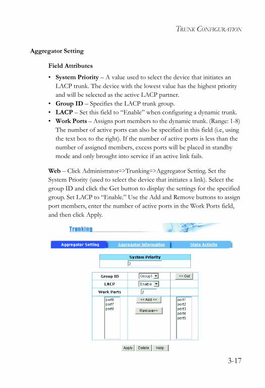
• System Priority – A value used to select the device that initiates an LACP trunk. The device with the lowest value has the highest priority and will be selected as the active LACP partner.
• Group ID – Specifies the LACP trunk group. • LACP – Set this field to “Enable” when configuring a dynamic trunk.• Work Ports – Assigns port members to the dynamic trunk. (Range: 1-8)
The number of active ports can also be specified in this field (i.e, using the text box to the right). If the number of active ports is less than the number of assigned members, excess ports will be placed in standby mode and only brought into service if an active link fails.
Web – Click Administrator=>Trunking=>Aggregator Setting. Set the System Priority (used to select the device that initiates a link). Select the group ID and click the Get button to display the settings for the specified group. Set LACP to “Enable.” Use the Add and Remove buttons to assign port members, enter the number of active ports in the Work Ports field, and then click Apply.
3-17
CONFIGURING THE SWITCH
Aggregator Information
Field Attributes
Static Trunks• Group Key – Displays static trunks.• Port No – The port members assigned to the trunk.
Dynamic Trunks• Actor – The device that initiated the trunk.• Partner – The device that responded to a link initialization request.• Priority – The priority used to select the device that initiates the trunk if
both ends of the link are set to the LACP State of “Active.” This is the same as System Priority on the Aggregator Setting page.
• MAC – The physical address of the devices at both ends of the link.• Port No – Active port members. (Other ports may be in standby mode.)• Key – Only one dynamic trunk can be activated between two devices, so
a key is sent to the partner device to uniquely identify each trunk. A trunk can only be formed if the devices at both ends of a link use the same key. A key is automatically generated by the switch when configuring a trunk.
• Active – Indicates whether a port has been set to actively initiate a trunk when an LACP partner is detected at the other end of the link. This field is configured in the State Activity page.
3-18
TRUNK CONFIGURATION
Web – Click Administrator=>Trunking=>Aggregator Information to display currently configured trunks and group members.
3-19
CONFIGURING THE SWITCH
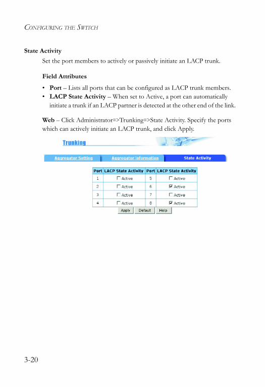
State Activity Set the port members to actively or passively initiate an LACP trunk.
Field Attributes
• Port – Lists all ports that can be configured as LACP trunk members.• LACP State Activity – When set to Active, a port can automatically
initiate a trunk if an LACP partner is detected at the other end of the link.
Web – Click Administrator=>Trunking=>State Activity. Specify the ports which can actively initiate an LACP trunk, and click Apply.
3-20
FORWARDING AND FILTERING
Forwarding and FilteringThis switch supports the following types of traffic filtering:
• Multicast Filtering – This switch can forward multicast traffic to host devices that request to join a multicast service, and filter multicast traffic for all other ports which do not require multicast services.
• Static MAC Address – Binds a physical address to a specific port and VLAN. Traffic with a source or destination address found in the static address table will only be passed through the specified interface.
• Port Security – Disables address learning for the specified port. Valid addresses must be learned during a initial training period or statically configured.
• MAC Filtering – Filters specified addresses from the switch or from a specific VLAN.
Configuring Multicast FilteringMulticasting is used to support real-time applications such as video conferencing or streaming audio. A multicast server does not have to establish a separate connection with each client. It merely broadcasts its service to the network, and any hosts that want to receive the multicast register with their local multicast switch/router. Although this approach reduces the network overhead required by a multicast server, the broadcast traffic must be carefully pruned at every multicast switch/router it passes through to ensure that traffic is only passed on to hosts that subscribed to this service.
This switch uses Internet Group Management Protocol (IGMP) to query for any attached hosts that want to receive a specific multicast service. It identifies the ports containing hosts requesting to join a service and sends data out to those ports only. It then propagates the service request up to any neighboring multicast switch/router to ensure that it will continue to receive the multicast service. This procedure is also called multicast filtering.
3-21
CONFIGURING THE SWITCH
The purpose of multicast filtering is to optimize a switched network’s performance, so multicast packets will only be forwarded to those ports containing multicast group hosts or multicast routers/switches, instead of flooding traffic to all ports in the subnet.
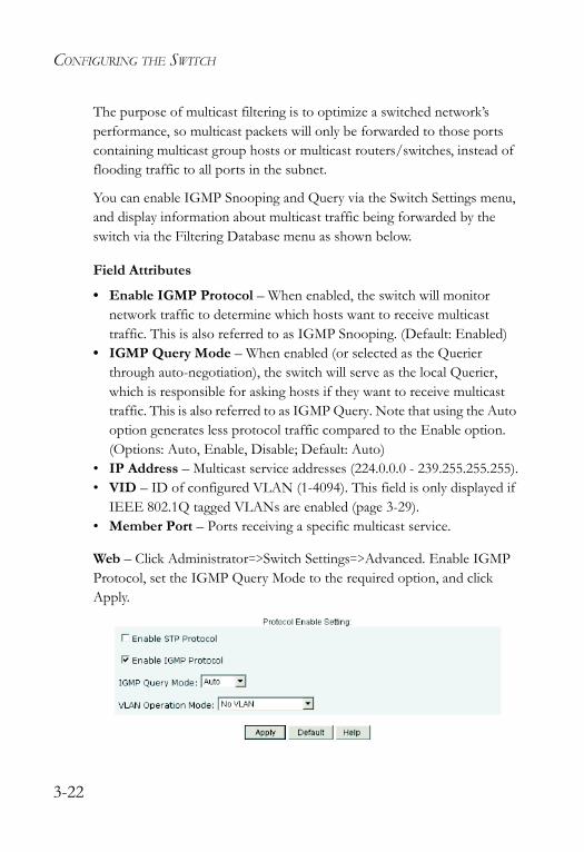
You can enable IGMP Snooping and Query via the Switch Settings menu, and display information about multicast traffic being forwarded by the switch via the Filtering Database menu as shown below.
Field Attributes
• Enable IGMP Protocol – When enabled, the switch will monitor network traffic to determine which hosts want to receive multicast traffic. This is also referred to as IGMP Snooping. (Default: Enabled)
• IGMP Query Mode – When enabled (or selected as the Querier through auto-negotiation), the switch will serve as the local Querier, which is responsible for asking hosts if they want to receive multicast traffic. This is also referred to as IGMP Query. Note that using the Auto option generates less protocol traffic compared to the Enable option. (Options: Auto, Enable, Disable; Default: Auto)
• IP Address – Multicast service addresses (224.0.0.0 - 239.255.255.255).• VID – ID of configured VLAN (1-4094). This field is only displayed if
IEEE 802.1Q tagged VLANs are enabled (page 3-29).• Member Port – Ports receiving a specific multicast service.
Web – Click Administrator=>Switch Settings=>Advanced. Enable IGMP Protocol, set the IGMP Query Mode to the required option, and click Apply.
3-22

FORWARDING AND FILTERING
Click Administrator=>Filtering Database=>IGMP Snooping.
3-23
CONFIGURING THE SWITCH
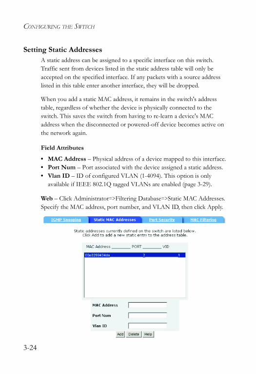
Setting Static AddressesA static address can be assigned to a specific interface on this switch. Traffic sent from devices listed in the static address table will only be accepted on the specified interface. If any packets with a source address listed in this table enter another interface, they will be dropped.
When you add a static MAC address, it remains in the switch's address table, regardless of whether the device is physically connected to the switch. This saves the switch from having to re-learn a device's MAC address when the disconnected or powered-off device becomes active on the network again.
Field Attributes
• MAC Address – Physical address of a device mapped to this interface.• Port Num – Port associated with the device assigned a static address.• Vlan ID – ID of configured VLAN (1-4094). This option is only
available if IEEE 802.1Q tagged VLANs are enabled (page 3-29).
Web – Click Administrator=>Filtering Database=>Static MAC Addresses. Specify the MAC address, port number, and VLAN ID, then click Apply.
3-24
FORWARDING AND FILTERING
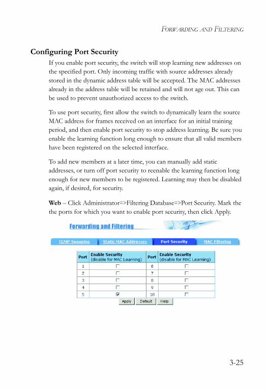
Configuring Port SecurityIf you enable port security, the switch will stop learning new addresses on the specified port. Only incoming traffic with source addresses already stored in the dynamic address table will be accepted. The MAC addresses already in the address table will be retained and will not age out. This can be used to prevent unauthorized access to the switch.
To use port security, first allow the switch to dynamically learn the source MAC address for frames received on an interface for an initial training period, and then enable port security to stop address learning. Be sure you enable the learning function long enough to ensure that all valid members have been registered on the selected interface.
To add new members at a later time, you can manually add static addresses, or turn off port security to reenable the learning function long enough for new members to be registered. Learning may then be disabled again, if desired, for security.
Web – Click Administrator=>Filtering Database=>Port Security. Mark the the ports for which you want to enable port security, then click Apply.
3-25
CONFIGURING THE SWITCH
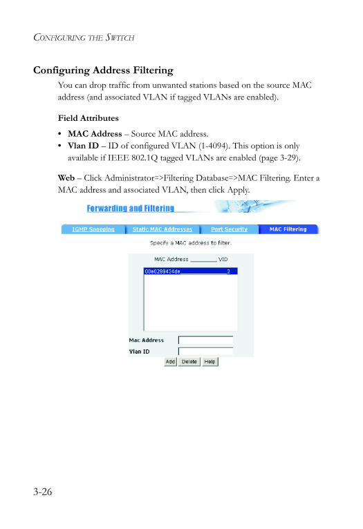
Configuring Address FilteringYou can drop traffic from unwanted stations based on the source MAC address (and associated VLAN if tagged VLANs are enabled).
Field Attributes
• MAC Address – Source MAC address.• Vlan ID – ID of configured VLAN (1-4094). This option is only
available if IEEE 802.1Q tagged VLANs are enabled (page 3-29).
Web – Click Administrator=>Filtering Database=>MAC Filtering. Enter a MAC address and associated VLAN, then click Apply.
3-26
VLAN CONFIGURATION
VLAN Configuration
OverviewIn large networks, routers are used to isolate broadcast traffic for each subnet into separate domains. This switch provides a similar service at Layer 2 by using VLANs to organize any group of network nodes into separate broadcast domains. VLANs confine broadcast traffic to the originating group, and can eliminate broadcast storms in large networks. This also provides a more secure and cleaner network environment.
VLANs provide greater network efficiency by reducing broadcast traffic, and allow you to make network changes without having to update IP addresses or IP subnets. VLANs provide a high level of network security since traffic must pass through a Layer 3 switch to reach a different VLAN.
This switch supports the following VLAN features:
• Port-based VLANs for isolating user groups or subnets • Protocol-based VLANs for isolating specific protocol subnets• IEEE 802.1Q tagged VLANs that can span across the network
(Up to 255 VLANs based on the IEEE 802.1Q standard)• Distributed VLAN learning across multiple switches using tagging and
GVRP dynamic registration protocol• Port overlapping, allowing a port to participate in multiple VLANs
3-27
CONFIGURING THE SWITCH
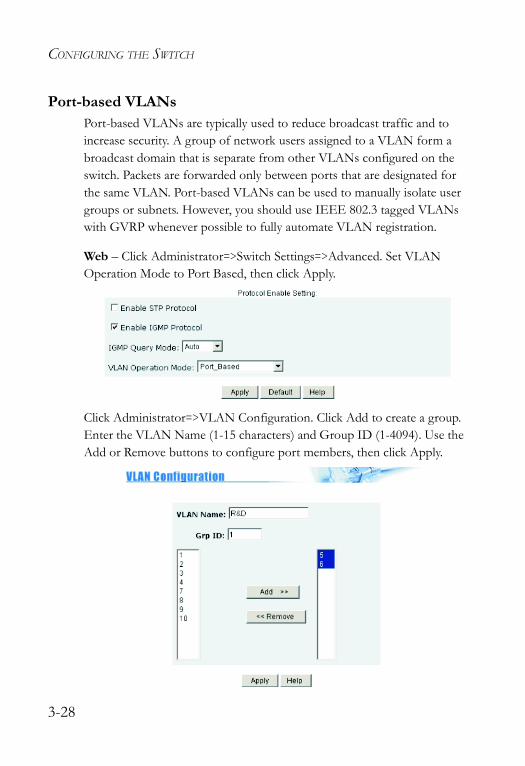
Port-based VLANsPort-based VLANs are typically used to reduce broadcast traffic and to increase security. A group of network users assigned to a VLAN form a broadcast domain that is separate from other VLANs configured on the switch. Packets are forwarded only between ports that are designated for the same VLAN. Port-based VLANs can be used to manually isolate user groups or subnets. However, you should use IEEE 802.3 tagged VLANs with GVRP whenever possible to fully automate VLAN registration.
Web – Click Administrator=>Switch Settings=>Advanced. Set VLAN Operation Mode to Port Based, then click Apply.
Click Administrator=>VLAN Configuration. Click Add to create a group.Enter the VLAN Name (1-15 characters) and Group ID (1-4094). Use the Add or Remove buttons to configure port members, then click Apply.
3-28
VLAN CONFIGURATION
Tag-based VLANsAn IEEE 802.1Q VLAN is a group of ports located anywhere in the network, but communicate as though they belong to the same physical segment by using frame tags to indicate VLAN membership. Tagged VLANs can help to simplify network management by allowing you to move devices to a new VLAN without having to change any physical connections. You can also configure the switch to interoperate with existing tag-based VLAN networks and legacy non-tag networks by specifying whether or not the switch ports transmit tagged frames.
Assigning Ports to VLANs – You must assign each port to the VLAN group(s) in which it will participate. By default all ports are assigned to VLAN 1 as untagged ports. Add a port as a tagged port if you want it to carry traffic for one or more VLANs, and any intermediate network devices or the host at the other end of the connection supports VLANs. Then assign ports on the other VLAN-aware network devices along the path that will carry this traffic to the same VLAN(s), either manually or dynamically using GVRP. However, if you want a port on this switch to participate in one or more VLANs, but none of the intermediate network devices nor the host at the other end of the connection supports VLANs, then you should add this port to the VLAN as an untagged port.
Note: VLAN-tagged frames can pass through VLAN-aware or VLAN- unaware network interconnection devices, but should not be used for any end-node host that does not support VLAN tagging.
VLAN Classification – When the switch receives a frame, it classifies the frame in one of two ways. If the frame is untagged, the switch assigns the frame to an associated VLAN (based on the PVID of the receiving port). If the frame is tagged, the switch uses the tagged VLAN ID to identify the port broadcast domain of the frame.
Port Overlapping – Port overlapping can be used to allow access to commonly shared network resources among different VLAN groups, such as file servers or printers. Note that if you implement VLANs which do
3-29
CONFIGURING THE SWITCH
not overlap, but still need to communicate, you can connect them by using a Layer-3 router or switch.
Protocol VLANs – This switch also supports VLANs based on specific protocol types, such as IPX and AppleTalk. When a protocol is bound to a VLAN, the switch will only forward packets carrying the specified protocol tag. However, regardless of the protocol type, remember that traffic must still be passed though a router to reach a different subnet.
Automatic VLAN Registration – GVRP (GARP VLAN Registration Protocol) defines a system whereby the switch can automatically learn the VLANs to which each endstation should be assigned. If an endstation (or its network adapter) supports the IEEE 802.1Q VLAN protocol, it can be configured to broadcast a message to your network indicating the VLAN groups it wants to join. When this switch receives these messages, it will automatically place the receiving port in the specified VLANs and forward the message to all other ports. When the message arrives at another switch that supports GVRP, it will also place the receiving port in the specified VLANs and pass the message on to all other ports. VLAN requirements are propagated in this way throughout the network. This allows GVRP-compliant devices to be automatically configured for VLAN groups based solely on endstation requests.
To implement GVRP in a network, first add the host devices to the required VLANs (using the operating system or other application software), so that these VLANs can be propagated onto the network. For both the edge switches attached directly to these hosts, and core switches in the network, enable GVRP on the links between these devices. You should also determine security boundaries in the network and disable GVRP on ports to prevent advertisements from being propagated.
Note: If you have host devices that do not support GVRP, you should configure port-based or untagged VLANs for the switch ports connected to these devices. But you can still enable GVRP on network ports for these edge switches, as well as on the core switches in the network.
3-30
VLAN CONFIGURATION
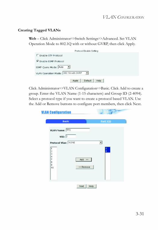
Creating Tagged VLANs
Web – Click Administrator=>Switch Settings=>Advanced. Set VLAN Operation Mode to 802.1Q with or without GVRP, then click Apply.
Click Administrator=>VLAN Configuration=>Basic. Click Add to create a group. Enter the VLAN Name (1-15 characters) and Group ID (2-4094). Select a protocol type if you want to create a protocol based VLAN. Use the Add or Remove buttons to configure port members, then click Next.
3-31
CONFIGURING THE SWITCH
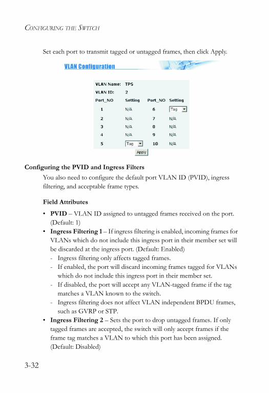
Set each port to transmit tagged or untagged frames, then click Apply.
Configuring the PVID and Ingress FiltersYou also need to configure the default port VLAN ID (PVID), ingress filtering, and acceptable frame types.
Field Attributes
• PVID – VLAN ID assigned to untagged frames received on the port. (Default: 1)
• Ingress Filtering 1 – If ingress filtering is enabled, incoming frames for VLANs which do not include this ingress port in their member set will be discarded at the ingress port. (Default: Enabled)- Ingress filtering only affects tagged frames. - If enabled, the port will discard incoming frames tagged for VLANs
which do not include this ingress port in their member set. - If disabled, the port will accept any VLAN-tagged frame if the tag
matches a VLAN known to the switch. - Ingress filtering does not affect VLAN independent BPDU frames,
such as GVRP or STP.• Ingress Filtering 2 – Sets the port to drop untagged frames. If only
tagged frames are accepted, the switch will only accept frames if the frame tag matches a VLAN to which this port has been assigned. (Default: Disabled)
3-32
VLAN CONFIGURATION
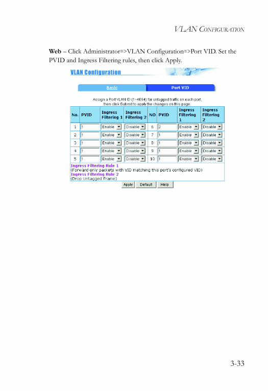
Web – Click Administrator=>VLAN Configuration=>Port VID. Set the PVID and Ingress Filtering rules, then click Apply.
3-33
CONFIGURING THE SWITCH
Spanning Tree Protocol ConfigurationThe Spanning Tree Protocol (STP) detects and disables network loops and provides backup links between switches, bridges, and routers to ensure that only one route exists between any two stations on the network. The backup links automatically take over when a primary link goes down.
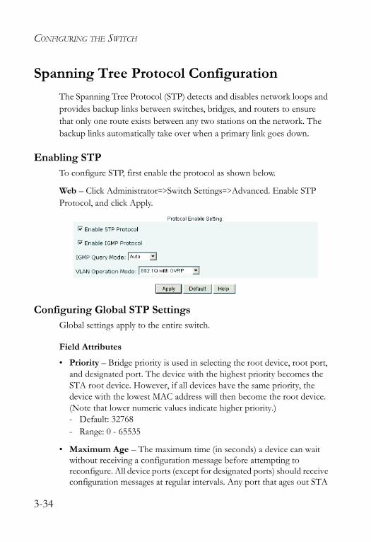
Enabling STPTo configure STP, first enable the protocol as shown below.
Web – Click Administrator=>Switch Settings=>Advanced. Enable STP Protocol, and click Apply.
Configuring Global STP SettingsGlobal settings apply to the entire switch.
Field Attributes
• Priority – Bridge priority is used in selecting the root device, root port, and designated port. The device with the highest priority becomes the STA root device. However, if all devices have the same priority, the device with the lowest MAC address will then become the root device. (Note that lower numeric values indicate higher priority.)- Default: 32768- Range: 0 - 65535
• Maximum Age – The maximum time (in seconds) a device can wait without receiving a configuration message before attempting to reconfigure. All device ports (except for designated ports) should receive configuration messages at regular intervals. Any port that ages out STA
3-34
SPANNING TREE PROTOCOL CONFIGURATION
information (provided in the last configuration message) becomes the designated port for the attached LAN. If it is a root port, a new root port is selected from among the device ports attached to the network. - Default: 20- Minimum: The higher of 6 or [2 x (Hello Time + 1)]- Maximum: The lower of 40 or [2 x (Forward Delay - 1)]
• Hello Time – Interval (in seconds) at which the root device transmits a configuration message. - Default: 2- Minimum: 1 - Maximum: The lower of 10 or [(Max. Message Age / 2) -1]
• Forward Delay Time – The maximum time (in seconds) the root device will wait before changing states (i.e., listening to learning to forwarding). This delay is required because every device must receive information about topology changes before it starts to forward frames. In addition, each port needs time to listen for conflicting information that would make it return to a blocking state; otherwise, temporary data loops might result.- Default: 15- Minimum: The higher of 4 or [(Max. Message Age / 2) + 1]- Maximum: 30
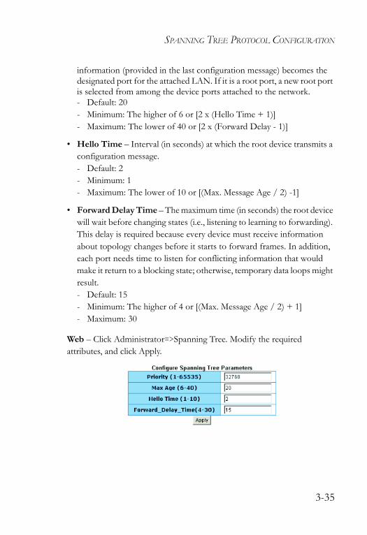
Web – Click Administrator=>Spanning Tree. Modify the required attributes, and click Apply.
3-35
CONFIGURING THE SWITCH
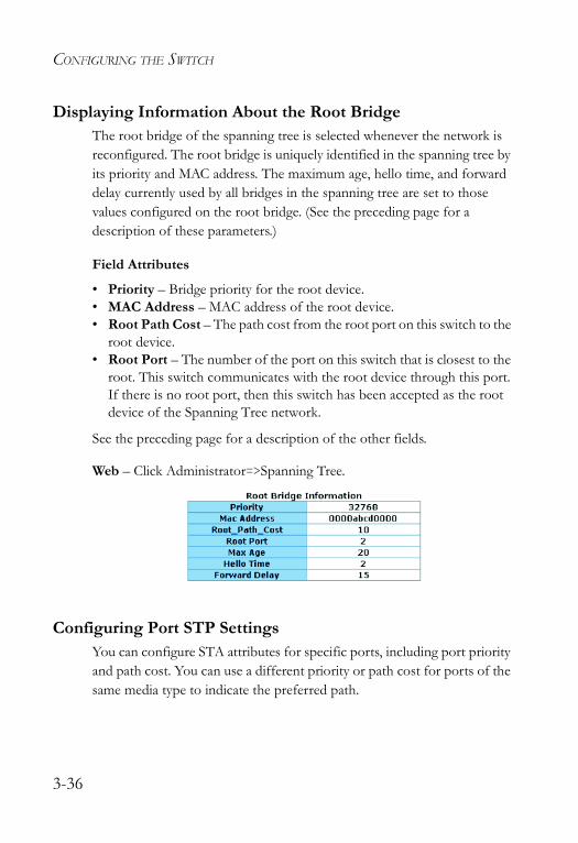
Displaying Information About the Root BridgeThe root bridge of the spanning tree is selected whenever the network is reconfigured. The root bridge is uniquely identified in the spanning tree by its priority and MAC address. The maximum age, hello time, and forward delay currently used by all bridges in the spanning tree are set to those values configured on the root bridge. (See the preceding page for a description of these parameters.)
Field Attributes
• Priority – Bridge priority for the root device.• MAC Address – MAC address of the root device.• Root Path Cost – The path cost from the root port on this switch to the
root device.• Root Port – The number of the port on this switch that is closest to the
root. This switch communicates with the root device through this port. If there is no root port, then this switch has been accepted as the root device of the Spanning Tree network.
See the preceding page for a description of the other fields.
Web – Click Administrator=>Spanning Tree.
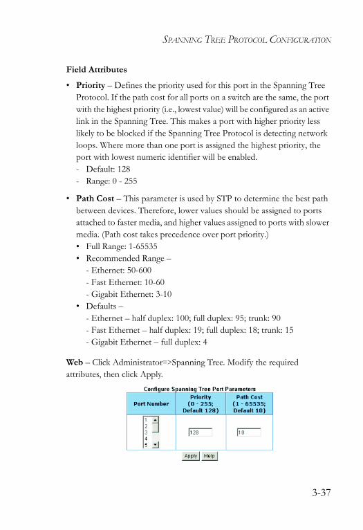
Configuring Port STP SettingsYou can configure STA attributes for specific ports, including port priority and path cost. You can use a different priority or path cost for ports of the same media type to indicate the preferred path.
3-36
SPANNING TREE PROTOCOL CONFIGURATION
Field Attributes
• Priority – Defines the priority used for this port in the Spanning Tree Protocol. If the path cost for all ports on a switch are the same, the port with the highest priority (i.e., lowest value) will be configured as an active link in the Spanning Tree. This makes a port with higher priority less likely to be blocked if the Spanning Tree Protocol is detecting network loops. Where more than one port is assigned the highest priority, the port with lowest numeric identifier will be enabled.- Default: 128- Range: 0 - 255
• Path Cost – This parameter is used by STP to determine the best path between devices. Therefore, lower values should be assigned to ports attached to faster media, and higher values assigned to ports with slower media. (Path cost takes precedence over port priority.) • Full Range: 1-65535• Recommended Range –
- Ethernet: 50-600- Fast Ethernet: 10-60- Gigabit Ethernet: 3-10
• Defaults –- Ethernet – half duplex: 100; full duplex: 95; trunk: 90- Fast Ethernet – half duplex: 19; full duplex: 18; trunk: 15- Gigabit Ethernet – full duplex: 4
Web – Click Administrator=>Spanning Tree. Modify the required attributes, then click Apply.
3-37
CONFIGURING THE SWITCH
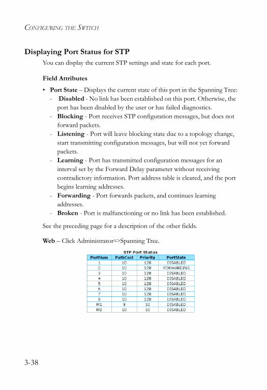
Displaying Port Status for STP You can display the current STP settings and state for each port.
Field Attributes
• Port State – Displays the current state of this port in the Spanning Tree:- Disabled - No link has been established on this port. Otherwise, the
port has been disabled by the user or has failed diagnostics.- Blocking - Port receives STP configuration messages, but does not
forward packets.- Listening - Port will leave blocking state due to a topology change,
start transmitting configuration messages, but will not yet forward packets.
- Learning - Port has transmitted configuration messages for an interval set by the Forward Delay parameter without receiving contradictory information. Port address table is cleared, and the port begins learning addresses.
- Forwarding - Port forwards packets, and continues learning addresses.
- Broken - Port is malfunctioning or no link has been established.
See the preceding page for a description of the other fields.
Web – Click Administrator=>Spanning Tree.
3-38
PORT MIRRORING
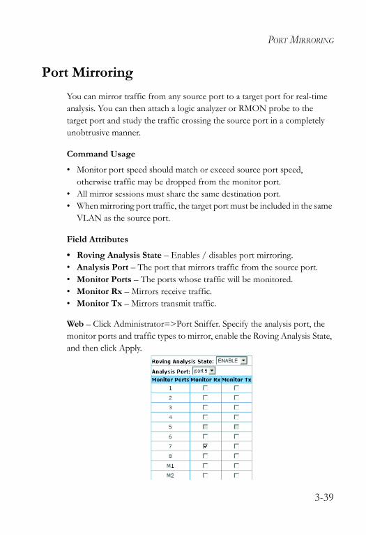
Port MirroringYou can mirror traffic from any source port to a target port for real-time analysis. You can then attach a logic analyzer or RMON probe to the target port and study the traffic crossing the source port in a completely unobtrusive manner.
Command Usage
• Monitor port speed should match or exceed source port speed, otherwise traffic may be dropped from the monitor port.
• All mirror sessions must share the same destination port.• When mirroring port traffic, the target port must be included in the same
VLAN as the source port.
Field Attributes
• Roving Analysis State – Enables / disables port mirroring.• Analysis Port – The port that mirrors traffic from the source port.• Monitor Ports – The ports whose traffic will be monitored.• Monitor Rx – Mirrors receive traffic.• Monitor Tx – Mirrors transmit traffic.
Web – Click Administrator=>Port Sniffer. Specify the analysis port, the monitor ports and traffic types to mirror, enable the Roving Analysis State, and then click Apply.
3-39
CONFIGURING THE SWITCH
Simple Network Management ProtocolThe switch includes an onboard agent that continuously monitors the status of its hardware, as well as the traffic passing through its ports, based on the Simple Network Management Protocol (SNMP). A network management station can access this information using software such as EliteView. Access rights to the onboard agent are controlled by community strings. To communicate with the switch, the management station must first submit a valid community string for authentication. The options for configuring community strings and related trap functions are described in the following sections.
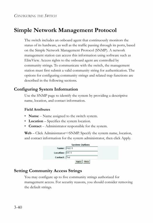
Configuring System InformationUse the SNMP page to identify the system by providing a descriptive name, location, and contact information.
Field Attributes
• Name – Name assigned to the switch system.• Location – Specifies the system location. • Contact – Administrator responsible for the system.
Web – Click Administrator=>SNMP. Specify the system name, location, and contact information for the system administrator, then click Apply.
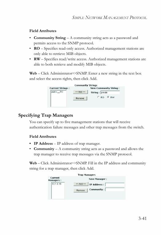
Setting Community Access Strings You may configure up to five community strings authorized for management access. For security reasons, you should consider removing the default strings.
3-40
SIMPLE NETWORK MANAGEMENT PROTOCOL
Field Attributes
• Community String – A community string acts as a password and permits access to the SNMP protocol.
• RO – Specifies read-only access. Authorized management stations are only able to retrieve MIB objects.
• RW – Specifies read/write access. Authorized management stations are able to both retrieve and modify MIB objects.
Web – Click Administrator=>SNMP. Enter a new string in the text box and select the access rights, then click Add.
Specifying Trap Managers You can specify up to five management stations that will receive authentication failure messages and other trap messages from the switch.
Field Attributes
• IP Address – IP address of trap manager.• Community – A community string acts as a password and allows the
trap manager to receive trap messages via the SNMP protocol.
Web – Click Administrator=>SNMP. Fill in the IP address and community string for a trap manager, then click Add.
3-41
CONFIGURING THE SWITCH
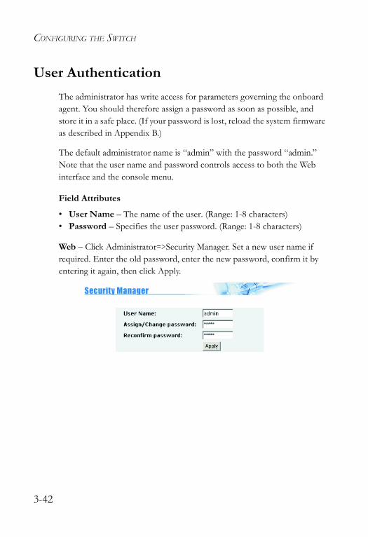
User AuthenticationThe administrator has write access for parameters governing the onboard agent. You should therefore assign a password as soon as possible, and store it in a safe place. (If your password is lost, reload the system firmware as described in Appendix B.)
The default administrator name is “admin” with the password “admin.” Note that the user name and password controls access to both the Web interface and the console menu.
Field Attributes
• User Name – The name of the user. (Range: 1-8 characters)• Password – Specifies the user password. (Range: 1-8 characters)
Web – Click Administrator=>Security Manager. Set a new user name if required. Enter the old password, enter the new password, confirm it by entering it again, then click Apply.
3-42
FIRMWARE AND CONFIGURATION SETTINGS
Firmware and Configuration Settings
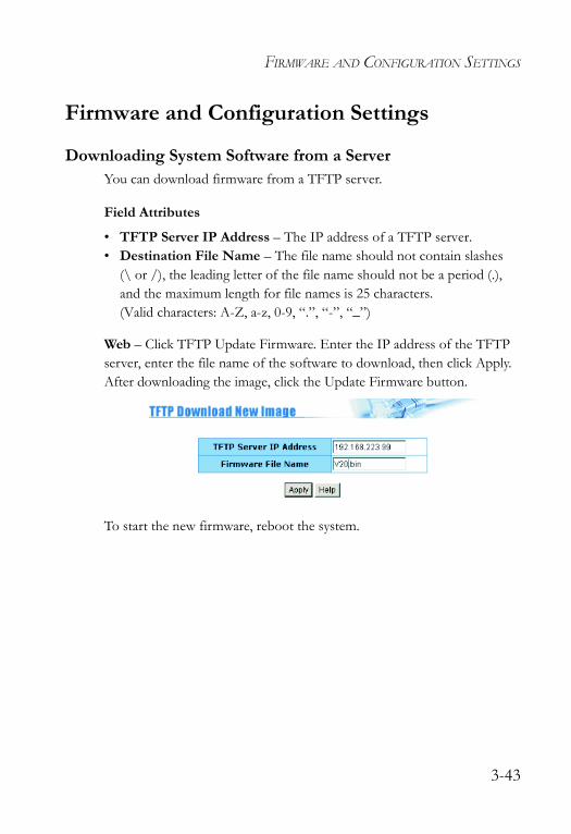
Downloading System Software from a ServerYou can download firmware from a TFTP server.
Field Attributes
• TFTP Server IP Address – The IP address of a TFTP server.• Destination File Name – The file name should not contain slashes
(\ or /), the leading letter of the file name should not be a period (.), and the maximum length for file names is 25 characters. (Valid characters: A-Z, a-z, 0-9, “.”, “-”, “_”)
Web – Click TFTP Update Firmware. Enter the IP address of the TFTP server, enter the file name of the software to download, then click Apply. After downloading the image, click the Update Firmware button.
To start the new firmware, reboot the system.
3-43
CONFIGURING THE SWITCH
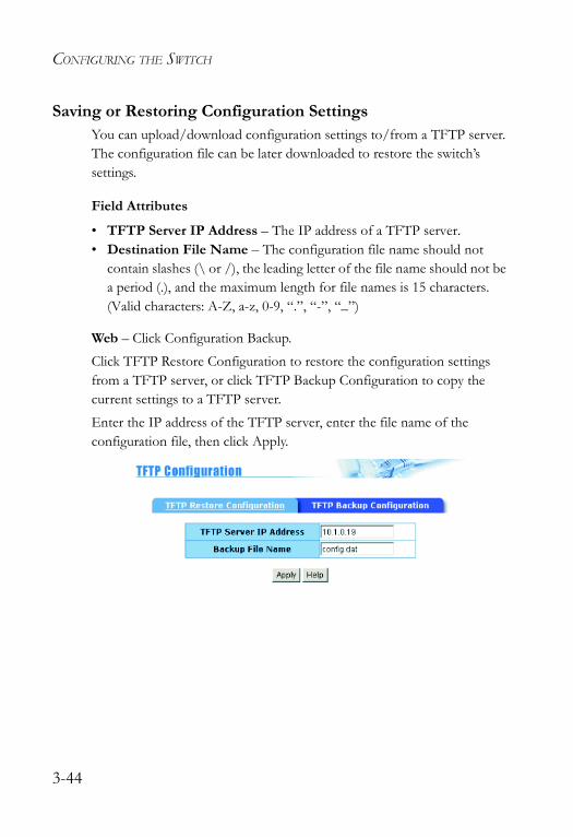
Saving or Restoring Configuration SettingsYou can upload/download configuration settings to/from a TFTP server. The configuration file can be later downloaded to restore the switch’s settings.
Field Attributes
• TFTP Server IP Address – The IP address of a TFTP server.• Destination File Name – The configuration file name should not
contain slashes (\ or /), the leading letter of the file name should not be a period (.), and the maximum length for file names is 15 characters. (Valid characters: A-Z, a-z, 0-9, “.”, “-”, “_”)
Web – Click Configuration Backup. Click TFTP Restore Configuration to restore the configuration settings from a TFTP server, or click TFTP Backup Configuration to copy the current settings to a TFTP server.Enter the IP address of the TFTP server, enter the file name of the configuration file, then click Apply.
3-44

RESETTING THE SYSTEM
Resetting the SystemWeb – Click Reset System. Click the Reset button to restore the default configuration settings.
Note: When restarting the system, it always runs the Power-On Self-Test.
Rebooting the SystemWeb – Click Reboot. Click the Reboot button to restart the switch.
Note: When restarting the system, it always runs the Power-On Self-Test.
3-45

CONFIGURING THE SWITCH
3-46
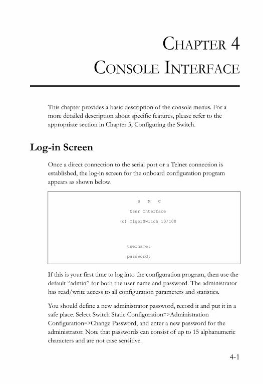
CHAPTER 4CONSOLE INTERFACE
This chapter provides a basic description of the console menus. For a more detailed description about specific features, please refer to the appropriate section in Chapter 3, Configuring the Switch.
Log-in ScreenOnce a direct connection to the serial port or a Telnet connection is established, the log-in screen for the onboard configuration program appears as shown below.
If this is your first time to log into the configuration program, then use the default “admin” for both the user name and password. The administrator has read/write access to all configuration parameters and statistics.
You should define a new administrator password, record it and put it in a safe place. Select Switch Static Configuration=>Administration Configuration=>Change Password, and enter a new password for the administrator. Note that passwords can consist of up to 15 alphanumeric characters and are not case sensitive.
S M C
User Interface
(c) TigerSwitch 10/100
username:
password:
4-1
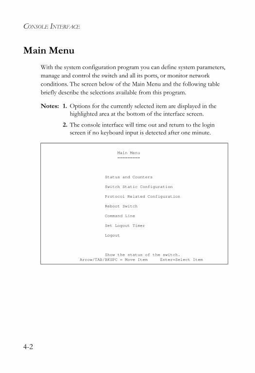
CONSOLE INTERFACE
Main MenuWith the system configuration program you can define system parameters, manage and control the switch and all its ports, or monitor network conditions. The screen below of the Main Menu and the following table briefly describe the selections available from this program.
Notes: 1. Options for the currently selected item are displayed in the highlighted area at the bottom of the interface screen.
2. The console interface will time out and return to the login screen if no keyboard input is detected after one minute.
Main Menu=========
Status and Counters
Switch Static Configuration
Protocol Related Configuration
Reboot Switch
Command Line
Set Logout Timer
Logout
Show the status of the switch.Arrow/TAB/BKSPC = Move Item Enter=Select Item
4-2
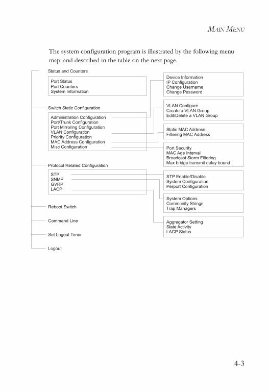
MAIN MENU
The system configuration program is illustrated by the following menu map, and described in the table on the next page.
Port Status
Port CountersSystem Information
Administration ConfigurationPort/Trunk ConfigurationPort Mirroring ConfigurationVLAN ConfigurationPriority ConfigurationMAC Address ConfigurationMisc Configuration
Device InformationIP ConfigurationChange UsernameChange Password
STPSNMPGVRPLACP
STP Enable/DisableSystem ConfigurationPerport Configuration
System OptionsCommunity StringsTrap Managers
Aggregator SettingState ActivityLACP Status
Status and Counters
Protocol Related Configuration
Switch Static Configuration
Reboot Switch
Command Line
Set Logout Timer
VLAN ConfigureCreate a VLAN GroupEdit/Delete a VLAN Group
Static MAC AddressFiltering MAC Address
Port SecurityMAC Age IntervalBroadcast Storm FilteringMax bridge transmit delay bound
Logout
4-3
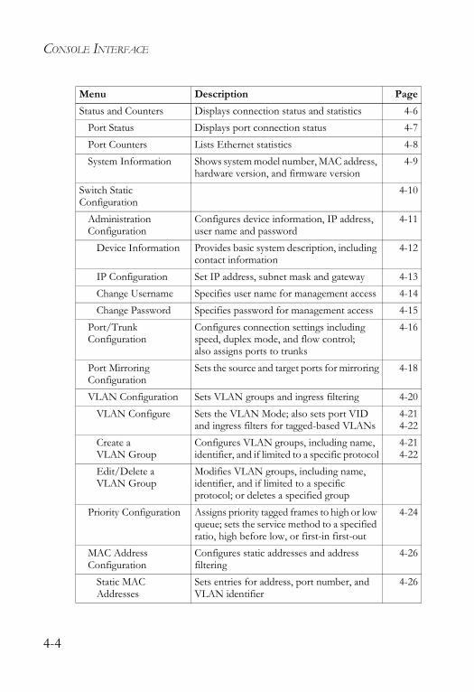
CONSOLE INTERFACE
Menu Description PageStatus and Counters Displays connection status and statistics 4-6
Port Status Displays port connection status 4-7Port Counters Lists Ethernet statistics 4-8System Information Shows system model number, MAC address,
hardware version, and firmware version4-9
Switch Static Configuration
4-10
Administration Configuration
Configures device information, IP address, user name and password
4-11
Device Information Provides basic system description, including contact information
4-12
IP Configuration Set IP address, subnet mask and gateway 4-13Change Username Specifies user name for management access 4-14Change Password Specifies password for management access 4-15
Port/Trunk Configuration
Configures connection settings including speed, duplex mode, and flow control; also assigns ports to trunks
4-16
Port Mirroring Configuration
Sets the source and target ports for mirroring 4-18
VLAN Configuration Sets VLAN groups and ingress filtering 4-20VLAN Configure Sets the VLAN Mode; also sets port VID
and ingress filters for tagged-based VLANs4-214-22
Create a VLAN Group
Configures VLAN groups, including name, identifier, and if limited to a specific protocol
4-214-22
Edit/Delete a VLAN Group
Modifies VLAN groups, including name, identifier, and if limited to a specific protocol; or deletes a specified group
Priority Configuration Assigns priority tagged frames to high or low queue; sets the service method to a specified ratio, high before low, or first-in first-out
4-24
MAC Address Configuration
Configures static addresses and address filtering
4-26
Static MAC Addresses
Sets entries for address, port number, and VLAN identifier
4-26
4-4
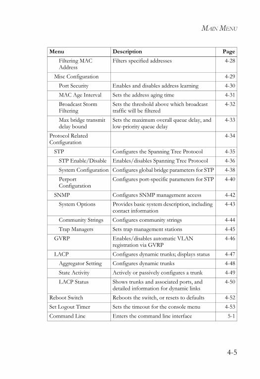
MAIN MENU
Filtering MAC Address
Filters specified addresses 4-28
Misc Configuration 4-29Port Security Enables and disables address learning 4-30MAC Age Interval Sets the address aging time 4-31Broadcast Storm Filtering
Sets the threshold above which broadcast traffic will be filtered
4-32
Max bridge transmit delay bound
Sets the maximum overall queue delay, and low-priority queue delay
4-33
Protocol Related Configuration
4-34
STP Configures the Spanning Tree Protocol 4-35STP Enable/Disable Enables/disables Spanning Tree Protocol 4-36System Configuration Configures global bridge parameters for STP 4-38Perport Configuration
Configures port-specific parameters for STP 4-40
SNMP Configures SNMP management access 4-42System Options Provides basic system description, including
contact information4-43
Community Strings Configures community strings 4-44Trap Managers Sets trap management stations 4-45
GVRP Enables/disables automatic VLAN registration via GVRP
4-46
LACP Configures dynamic trunks; displays status 4-47Aggregator Setting Configures dynamic trunks 4-48State Activity Actively or passively configures a trunk 4-49LACP Status Shows trunks and associated ports, and
detailed information for dynamic links4-50
Reboot Switch Reboots the switch, or resets to defaults 4-52Set Logout Timer Sets the timeout for the console menu 4-53Command Line Enters the command line interface 5-1
Menu Description Page
4-5
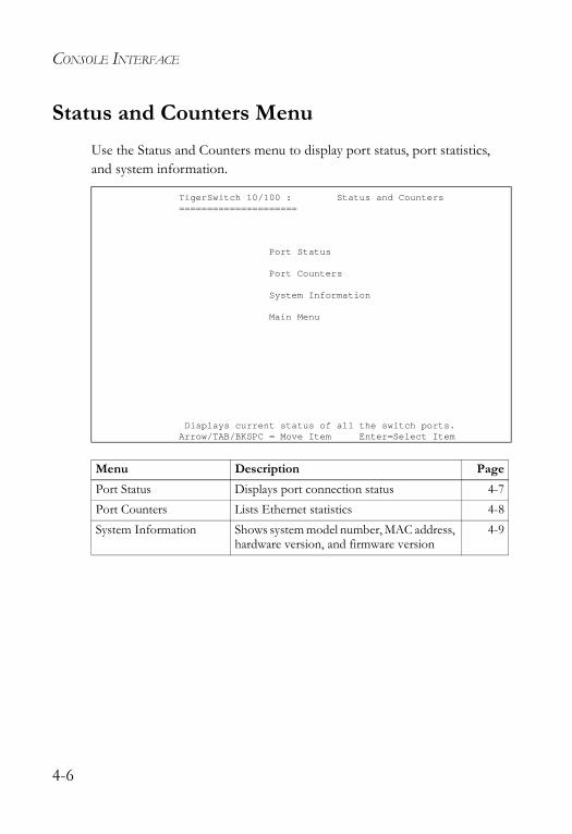
CONSOLE INTERFACE
Status and Counters MenuUse the Status and Counters menu to display port status, port statistics, and system information.
TigerSwitch 10/100 : Status and Counters=====================
Port Status
Port Counters
System Information
Main Menu
Displays current status of all the switch ports.Arrow/TAB/BKSPC = Move Item Enter=Select Item
Menu Description PagePort Status Displays port connection status 4-7Port Counters Lists Ethernet statistics 4-8System Information Shows system model number, MAC address,
hardware version, and firmware version4-9
4-6
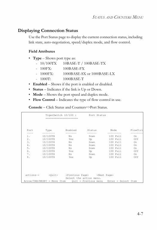
STATUS AND COUNTERS MENU
Displaying Connection Status Use the Port Status page to display the current connection status, including link state, auto-negotiation, speed/duplex mode, and flow control.
Field Attributes
• Type – Shows port type as:- 10/100TX 10BASE-T / 100BASE-TX- 100FX: 100BASE-FX - 1000FX: 1000BASE-SX or 1000BASE-LX - 1000T: 1000BASE-T
• Enabled – Shows if the port is enabled or disabled. • Status – Indicates if the link is Up or Down. • Mode – Shows the port speed and duplex mode.• Flow Control – Indicates the type of flow control in use.
Console – Click Status and Counters=>Port Status.
TigerSwitch 10/100 : Port Status=====================
Port Type Enabled Status Mode FlowCtrl---- -------- ------- ------ --------- --------1. 10/100TX No Down 100 Full On2. 10/100TX Yes Up 100 Full Off3. 10/100TX No Down 100 Full On4. 10/100TX No Down 100 Full On5. 10/100TX No Down 100 Full On6. 10/100TX Yes Up 100 Full Off7. 10/100TX No Down 100 Full On8. 10/100TX Yes Up 100 Full Off
actions-> <Quit> <Previous Page> <Next Page>Select the action menu.
Arrow/TAB/BKSPC = Move Item Quit = Previous menu Enter = Select Item
4-7
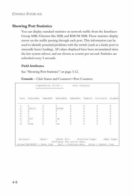
CONSOLE INTERFACE
Showing Port StatisticsYou can display standard statistics on network traffic from the Interfaces Group MIB, Ethernet-like MIB, and RMOM MIB. These statistics display errors on the traffic passing through each port. This information can be used to identify potential problems with the switch (such as a faulty port or unusually heavy loading). All values displayed have been accumulated since the last system reboot, and are shown as counts per second. Statistics are refreshed every 5 seconds.
Field Attributes
See “Showing Port Statistics” on page 3-12.
Console – Click Status and Counters=>Port Counters.
TigerSwitch 10/100 : Port Counters=====================
Port TxGoodPkt TxBadPkt RxGoodPkt RxBadPkt TxAbort Collision DropPkt
----------------------------------------------------------------------------1. 0 0 0 0 0 0 02. 386113 0 481088 0 0 0 03. 0 0 0 0 0 0 04. 0 0 0 0 0 0 05. 0 0 0 0 0 0 06. 2527 0 136 0 0 0 07. 0 0 0 0 0 0 08. 2928 0 136 0 0 0 0
actions-> <Quit> <Reset All> <Previous Page> <Next Page>Configure the action menu.
Arrow/TAB/BKSPC = Move Item Quit = Previous menu Enter = Select Item
4-8
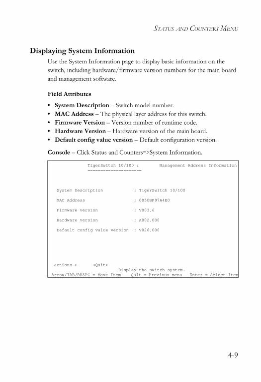
STATUS AND COUNTERS MENU
Displaying System InformationUse the System Information page to display basic information on the switch, including hardware/firmware version numbers for the main board and management software.
Field Attributes
• System Description – Switch model number.• MAC Address – The physical layer address for this switch. • Firmware Version – Version number of runtime code.• Hardware Version – Hardware version of the main board.• Default config value version – Default configuration version.
Console – Click Status and Counters=>System Information.
TigerSwitch 10/100 : Management Address Information=====================
System Description : TigerSwitch 10/100
MAC Address : 0050BF97A4E0
Firmware version : V003.6
Hardware version : A002.000
Default config value version : V026.000
actions-> <Quit>Display the switch system.
Arrow/TAB/BKSPC = Move Item Quit = Previous menu Enter = Select Item
4-9
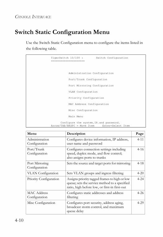
CONSOLE INTERFACE
Switch Static Configuration MenuUse the Switch Static Configuration menu to configure the items listed in the following table.
TigerSwitch 10/100 : Switch Configuration=====================
Administration Configuration
Port/Trunk Configuration
Port Mirroring Configuration
VLAN Configuration
Priority Configuration
MAC Address Configuration
Misc Configuration
Main Menu
Configure the system,IP,and password.Arrow/TAB/BKSPC = Move Item Enter=Select Item
Menu Description PageAdministration Configuration
Configures device information, IP address, user name and password
4-11
Port/Trunk Configuration
Configures connection settings including speed, duplex mode, and flow control; also assigns ports to trunks
4-16
Port Mirroring Configuration
Sets the source and target ports for mirroring 4-18
VLAN Configuration Sets VLAN groups and ingress filtering 4-20Priority Configuration Assigns priority tagged frames to high or low
queue; sets the service method to a specified ratio, high before low, or first-in first-out
4-24
MAC Address Configuration
Configures static addresses and address filtering
4-26
Misc Configuration Configures port security, address aging, broadcast storm control, and maximum queue delay
4-29
4-10
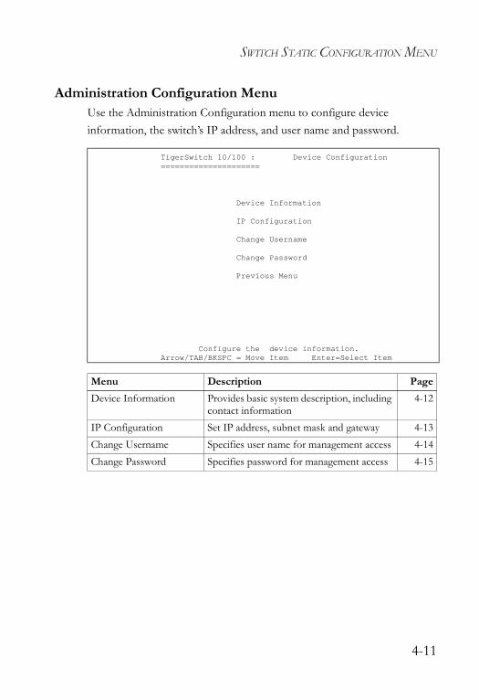
SWITCH STATIC CONFIGURATION MENU
Administration Configuration MenuUse the Administration Configuration menu to configure device information, the switch’s IP address, and user name and password.
TigerSwitch 10/100 : Device Configuration=====================
Device Information
IP Configuration
Change Username
Change Password
Previous Menu
Configure the device information.Arrow/TAB/BKSPC = Move Item Enter=Select Item
Menu Description PageDevice Information Provides basic system description, including
contact information4-12
IP Configuration Set IP address, subnet mask and gateway 4-13Change Username Specifies user name for management access 4-14Change Password Specifies password for management access 4-15
4-11
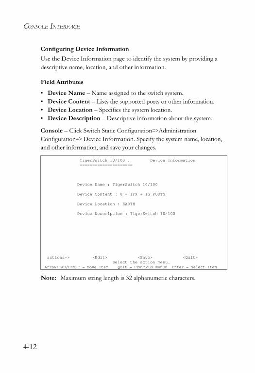
CONSOLE INTERFACE
Configuring Device InformationUse the Device Information page to identify the system by providing a descriptive name, location, and other information.
Field Attributes
• Device Name – Name assigned to the switch system.• Device Content – Lists the supported ports or other information.• Device Location – Specifies the system location. • Device Description – Descriptive information about the system.
Console – Click Switch Static Configuration=>Administration Configuration=> Device Information. Specify the system name, location, and other information, and save your changes.
Note: Maximum string length is 32 alphanumeric characters.
TigerSwitch 10/100 : Device Information=====================
Device Name : TigerSwitch 10/100
Device Content : 8 + 1FX + 1G PORTS
Device Location : EARTH
Device Description : TigerSwitch 10/100
actions-> <Edit> <Save> <Quit>Select the action menu.
Arrow/TAB/BKSPC = Move Item Quit = Previous menuu Enter = Select Item
4-12
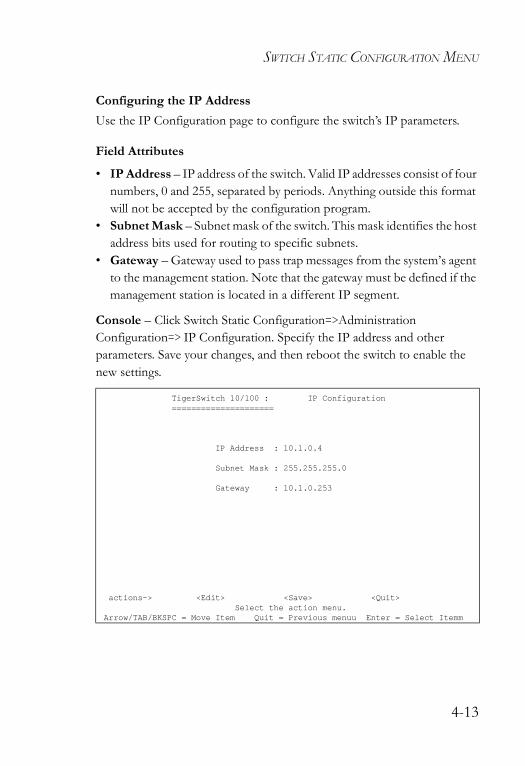
SWITCH STATIC CONFIGURATION MENU
Configuring the IP AddressUse the IP Configuration page to configure the switch’s IP parameters.
Field Attributes
• IP Address – IP address of the switch. Valid IP addresses consist of four numbers, 0 and 255, separated by periods. Anything outside this format will not be accepted by the configuration program.
• Subnet Mask – Subnet mask of the switch. This mask identifies the host address bits used for routing to specific subnets.
• Gateway – Gateway used to pass trap messages from the system’s agent to the management station. Note that the gateway must be defined if the management station is located in a different IP segment.
Console – Click Switch Static Configuration=>Administration Configuration=> IP Configuration. Specify the IP address and other parameters. Save your changes, and then reboot the switch to enable the new settings.
TigerSwitch 10/100 : IP Configuration=====================
IP Address : 10.1.0.4
Subnet Mask : 255.255.255.0
Gateway : 10.1.0.253
actions-> <Edit> <Save> <Quit>Select the action menu.
Arrow/TAB/BKSPC = Move Item Quit = Previous menuu Enter = Select Itemm
4-13

CONSOLE INTERFACE
Configuring the User NameUse the Change Username page to change the user name used to authenticate management access.
The default administrator name is “admin.” Note that the user name and password control access to both the Web interface and the console menu.
Console – Click Switch Static Configuration=>Administration Configuration=> Change Username. Set a new user name, and save it.
Note: Maximum string length is 8 alphanumeric characters.
TigerSwitch 10/100 : UserName Configuration.=====================
UserName : admin
actions-> <Edit> <Save> <Quit>Select the action menu.
Arrow/TAB/BKSPC = Move Item Quit = Previous menuu Enter = Select Item
4-14
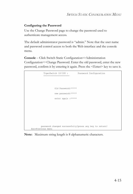
SWITCH STATIC CONFIGURATION MENU
Configuring the PasswordUse the Change Password page to change the password used to authenticate management access.
The default administrator password is “admin.” Note that the user name and password control access to both the Web interface and the console menu.
Console – Click Switch Static Configuration=>Administration Configuration=> Change Password. Enter the old password, enter the new password, confirm it by entering it again. Press the <Enter> key to save it.
Note: Maximum string length is 8 alphanumeric characters.
TigerSwitch 10/100 : Password Configuration=====================
Old Password:*****
new password:*****
enter again :*****
password changed successfully!press any key to return!Esc=Previous menu
4-15
CONSOLE INTERFACE
Configuring Interface ConnectionsUse the Port/Trunk Configuration page to enable/disable an interface, set auto-negotiation, or manually set the speed and duplex mode, and flow control parameters.
Field Attributes
• Type – Shows port type (page 4-7).• Enabled – Allows you to manually disable an interface. You can disable
an interface due to abnormal behavior (e.g., excessive collisions), and then reenable it after the problem has been resolved. You may also disable an interface for security reasons.
• Auto Negotiate – Enables/disables auto-negotiation. • Speed/Duplex Config – Manually sets port speed and duplex mode.• Flow Control – Allows automatic or manual selection of flow control.
Flow control can eliminate frame loss by “blocking” traffic from end stations or segments connected directly to the switch when its buffers fill. When enabled, back pressure is used for half-duplex operation and IEEE 802.3x for full-duplex operation. (Avoid using flow control on a port connected to a hub unless it is actually required to solve a problem. Otherwise back pressure jamming signals may degrade overall performance for the segment attached to the hub.)
• Group – Assigns a port to a trunk group. (Range: 1-4)To set a trunk as a dynamic link, use the LACP menu (page 4-47).
Note: Auto-negotiation must be disabled before you can manually force a port to use the speed/duplex mode or flow control options.
4-16
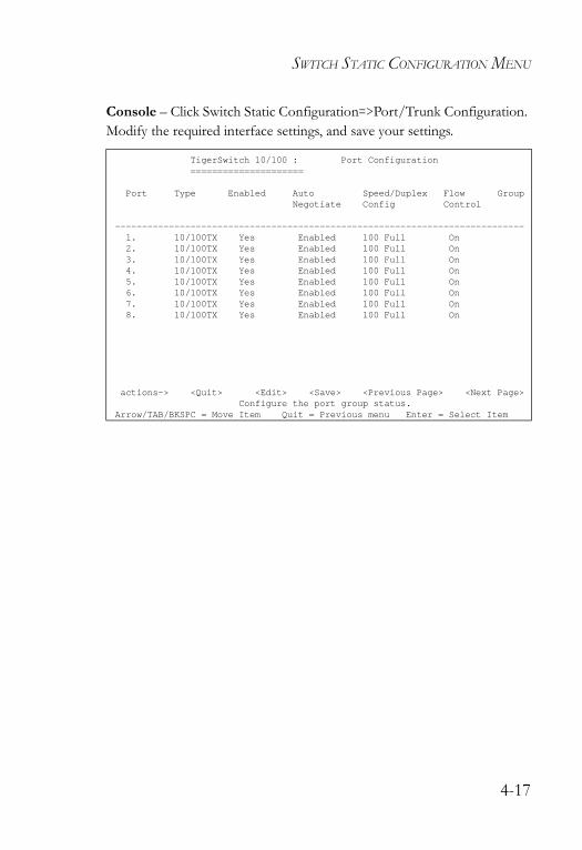
SWITCH STATIC CONFIGURATION MENU
Console – Click Switch Static Configuration=>Port/Trunk Configuration. Modify the required interface settings, and save your settings.
TigerSwitch 10/100 : Port Configuration=====================
Port Type Enabled Auto Speed/Duplex Flow GroupNegotiate Config Control
----------------------------------------------------------------------------1. 10/100TX Yes Enabled 100 Full On2. 10/100TX Yes Enabled 100 Full On3. 10/100TX Yes Enabled 100 Full On4. 10/100TX Yes Enabled 100 Full On5. 10/100TX Yes Enabled 100 Full On6. 10/100TX Yes Enabled 100 Full On7. 10/100TX Yes Enabled 100 Full On8. 10/100TX Yes Enabled 100 Full On
actions-> <Quit> <Edit> <Save> <Previous Page> <Next Page>Configure the port group status.
Arrow/TAB/BKSPC = Move Item Quit = Previous menu Enter = Select Item
4-17

CONSOLE INTERFACE
Configuring Port MirroringYou can mirror traffic from any source port to a target port for real-time analysis. You can then attach a logic analyzer or RMON probe to the target port and study the traffic crossing the source port in a completely unobtrusive manner.
Command Usage
• Monitor port speed should match or exceed source port speed, otherwise traffic may be dropped from the monitor port.
• All mirror sessions must share the same destination port.• When mirroring port traffic, the target port must be included in the same
VLAN as the source port.
4-18
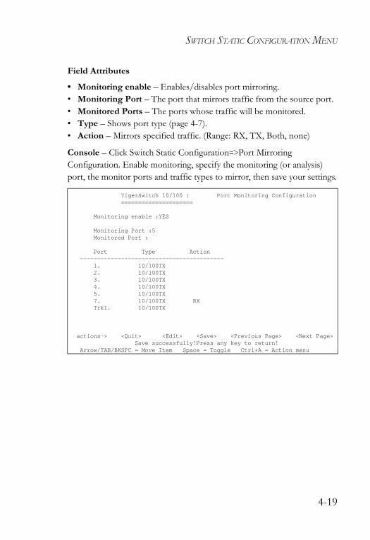
SWITCH STATIC CONFIGURATION MENU
Field Attributes
• Monitoring enable – Enables/disables port mirroring.• Monitoring Port – The port that mirrors traffic from the source port.• Monitored Ports – The ports whose traffic will be monitored.• Type – Shows port type (page 4-7).• Action – Mirrors specified traffic. (Range: RX, TX, Both, none)
Console – Click Switch Static Configuration=>Port Mirroring Configuration. Enable monitoring, specify the monitoring (or analysis) port, the monitor ports and traffic types to mirror, then save your settings.
TigerSwitch 10/100 : Port Monitoring Configuration=====================
Monitoring enable :YES
Monitoring Port :5Monitored Port :
Port Type Action------------------------------------------
1. 10/100TX2. 10/100TX3. 10/100TX4. 10/100TX5. 10/100TX7. 10/100TX RXTrk1. 10/100TX
actions-> <Quit> <Edit> <Save> <Previous Page> <Next Page>Save successfully!Press any key to return!
Arrow/TAB/BKSPC = Move Item Space = Toggle Ctrl+A = Action menu
4-19
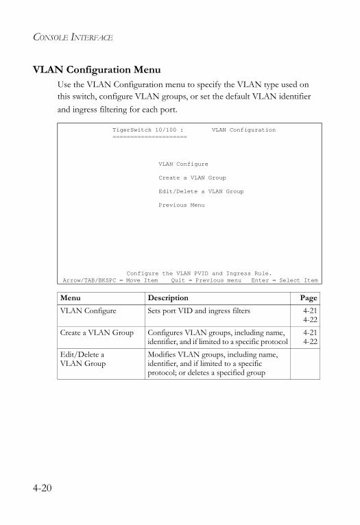
CONSOLE INTERFACE
VLAN Configuration MenuUse the VLAN Configuration menu to specify the VLAN type used on this switch, configure VLAN groups, or set the default VLAN identifier and ingress filtering for each port.
TigerSwitch 10/100 : VLAN Configuration=====================
VLAN Configure
Create a VLAN Group
Edit/Delete a VLAN Group
Previous Menu
Configure the VLAN PVID and Ingress Rule.Arrow/TAB/BKSPC = Move Item Quit = Previous menu Enter = Select Item
Menu Description PageVLAN Configure Sets port VID and ingress filters 4-21
4-22Create a VLAN Group Configures VLAN groups, including name,
identifier, and if limited to a specific protocol4-214-22
Edit/Delete a VLAN Group
Modifies VLAN groups, including name, identifier, and if limited to a specific protocol; or deletes a specified group
4-20
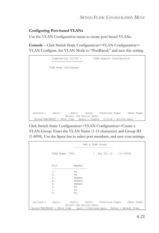
SWITCH STATIC CONFIGURATION MENU
Configuring Port-based VLANsUse the VLAN Configuration menu to create port-based VLANs.
Console – Click Switch Static Configuration=>VLAN Configuration=> VLAN Configure. Set VLAN Mode to “PortBased,” and save this setting.
Click Switch Static Configuration=>VLAN Configuration=>Create a VLAN Group. Enter the VLAN Name (1-15 characters) and Group ID (1-4094). Use the Space bar to select port members, and save your settings.
TigerSwitch 10/100 : VLAN Support Configuraton=====================
VLAN Mode :PortBased
actions-> <Quit> <Edit> <Save> <Previous Page> <Next Page>Select the Action menu.
Arrow/TAB/BKSPC = Move Item Space = Toggle Ctrl+A = Action menu
Add a VLAN Group--------------------------
VLAN Name: [TPS ] Grp ID: [2 ](1~4094)
Port Member------------------------1. No2. No3. Member4. Member5. Member6. No7. No8. No
actions-> <Quit> <Edit> <Save> <Previous Page> <Next Page>Select the Action menu.
Arrow/TAB/BKSPC = Move Item Quit = Previous menu Enter = Select Item
4-21
CONSOLE INTERFACE
Configuring Tag-based VLANsUse the VLAN Configuration menu to create tag-based VLANs.
Field Attributes
When the VLAN mode is set “802.1Q” or “802.1QwithGVRP” (on the VLAN Configure page), the following attributes are displayed.
• PVID – VLAN ID assigned to untagged frames received on the port. (Default: 1)
• Ingress Filter 1 (NonMember Pkt) – If ingress filtering is enabled, incoming frames for VLANs which do not include this ingress port in their member set will be discarded at the ingress port. (Default: Drop)- Ingress filtering only affects tagged frames. - If enabled, the port will discard incoming frames tagged for VLANs
which do not include this ingress port in their member set. - If disabled, the port will accept any VLAN-tagged frame if the tag
matches a VLAN known to the switch. - Ingress filtering does not affect VLAN independent BPDU frames,
such as GVRP or STP.• Ingress Filter 2 (Untagged Pkt) – Sets the port to drop untagged frames.
If only tagged frames are accepted, the switch will only accept frames if the frame tag matches a VLAN to which this port has been assigned. (Default: Forward)
4-22
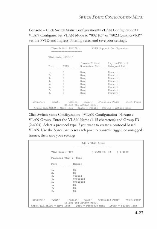
SWITCH STATIC CONFIGURATION MENU
Console – Click Switch Static Configuration=>VLAN Configuration=> VLAN Configure. Set VLAN Mode to “802.1Q” or “802.1QwithGVRP.” Set the PVID and Ingress Filtering rules, and save your settings.
Click Switch Static Configuration=>VLAN Configuration=>Create a VLAN Group. Enter the VLAN Name (1-15 characters) and Group ID (2-4094). Select a protocol type if you want to create a protocol based VLAN. Use the Space bar to set each port to transmit tagged or untagged frames, then save your settings.
TigerSwitch 10/100 : VLAN Support Configuraton=====================
VLAN Mode :802.1Q
IngressFilter1 IngressFilter2Port PVID NonMember Pkt Untagged Pkt-------------------------------------------------------1. 1 Drop Forward2. 1 Drop Forward3. 1 Drop Forward4. 1 Drop Forward5. 1 Drop Forward6. 1 Drop Forward7. 1 Drop Forward8. 1 Drop Forward
actions-> <Quit> <Edit> <Save> <Previous Page> <Next Page>Select the Action menu.
Arrow/TAB/BKSPC = Move Item Space = Toggle Ctrl+A = Action menu
Add a VLAN Group--------------------------
VLAN Name: [TPS ] VLAN ID: [2 ](1~4094)
Protocol VLAN : None
Port Member------------------------1. No2. No3. Tagged4. UnTagged5. UnTagged6. No7. No8. No
actions-> <Quit> <Edit> <Save> <Previous Page> <Next Page>Select the Action menu.
Arrow/TAB/BKSPC = Move Item Quit = Previous menu Enter = Select Item
4-23
CONSOLE INTERFACE
Configuring Queue PrioritiesUse the Priority Configuration page to specify which data packets have greater precedence when traffic is buffered in the switch due to congestion. This switch has two priority queues for each port. Data packets in a port’s high-priority queue is transmitted before those in the lower-priority queue.
You can map the frame priority tags (i.e., 0 - 7) to the high or low priority queues, and also set the method used to process priority traffic (i.e., first-in first-out, all high before low, or weighted round-robin).
Field Attributes
• Queue Assignment – The default priority levels are assigned according to recommendations in the IEEE 802.1p standard. However, you can map the priority levels to the switch’s output queues in any way that benefits application traffic for your own network. (Range: Low, High; Default: Low - Priority Tags 0-3, High - Priority Tags 4-7)
• High/Low Queue Service Ratio (H:L)- #:# (Weighted Round Robin) – Sets the preference given to packets
in the high-priority queue. This specifies the number of high-priority packets sent before one low-priority packet is sent. You can set this field to 1:1 to disable priority service. (Range: 1:1 - 7:1; Default: 2)
- FIFO (First Come First Served) – Packets are processed first-in first-out.
- H->L (All High before Low) – All packets in the high-priority queue are processed before any packets in the low-priority queue.
4-24
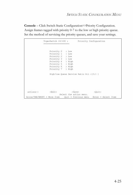
SWITCH STATIC CONFIGURATION MENU
Console – Click Switch Static Configuration=>Priority Configuration. Assign frames tagged with priority 0-7 to the low or high priority queue. Set the method of servicing the priority queues, and save your settings.
TigerSwitch 10/100 : Priority Configuration=====================
Priority 0 : LowPriority 1 : LowPriority 2 : LowPriority 3 : LowPriority 4 : HighPriority 5 : HighPriority 6 : HighPriority 7 : High
High/Low Queue Service Ratio H:L :[2:1 ]
actions-> <Edit> <Save> <Quit>Select the action menu.
Arrow/TAB/BKSPC = Move Item Quit = Previous menu Enter = Select Item
4-25
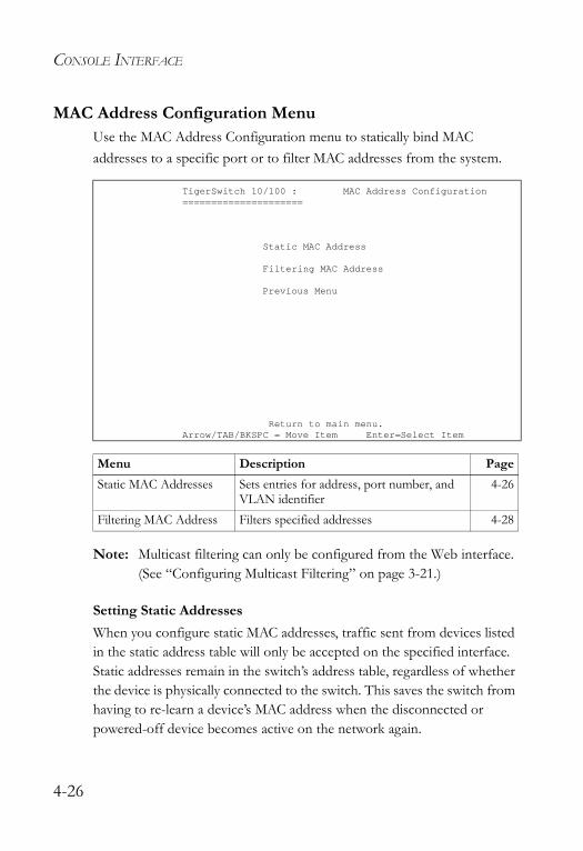
CONSOLE INTERFACE
MAC Address Configuration MenuUse the MAC Address Configuration menu to statically bind MAC addresses to a specific port or to filter MAC addresses from the system.
Note: Multicast filtering can only be configured from the Web interface. (See “Configuring Multicast Filtering” on page 3-21.)
Setting Static AddressesWhen you configure static MAC addresses, traffic sent from devices listed in the static address table will only be accepted on the specified interface. Static addresses remain in the switch’s address table, regardless of whether the device is physically connected to the switch. This saves the switch from having to re-learn a device’s MAC address when the disconnected or powered-off device becomes active on the network again.
TigerSwitch 10/100 : MAC Address Configuration=====================
Static MAC Address
Filtering MAC Address
Previous Menu
Return to main menu.Arrow/TAB/BKSPC = Move Item Enter=Select Item
Menu Description PageStatic MAC Addresses Sets entries for address, port number, and
VLAN identifier4-26
Filtering MAC Address Filters specified addresses 4-28
4-26
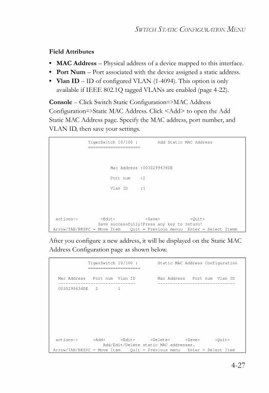
SWITCH STATIC CONFIGURATION MENU
Field Attributes
• MAC Address – Physical address of a device mapped to this interface.• Port Num – Port associated with the device assigned a static address.• Vlan ID – ID of configured VLAN (1-4094). This option is only
available if IEEE 802.1Q tagged VLANs are enabled (page 4-22).
Console – Click Switch Static Configuration=>MAC Address Configuration=>Static MAC Address. Click <Add> to open the Add Static MAC Address page. Specify the MAC address, port number, and VLAN ID, then save your settings.
After you configure a new address, it will be displayed on the Static MAC Address Configuration page as shown below.
TigerSwitch 10/100 : Add Static MAC Address=====================
Mac Address :0030299434DE
Port num :2
Vlan ID :1
actions-> <Edit> <Save> <Quit>Save successfully!Press any key to return!
Arrow/TAB/BKSPC = Move Item Quit = Previous menuu Enter = Select Itemm
TigerSwitch 10/100 : Static MAC Address Configuration=====================
Mac Address Port num Vlan ID Mac Address Port num Vlan ID------------------------------- -------------------------------0030299434DE 2 1
actions-> <Add> <Edit> <Delete> <Save> <Quit>Add/Edit/Delete static MAC addresses.
Arrow/TAB/BKSPC = Move Item Quit = Previous menu Enter = Select Item
4-27
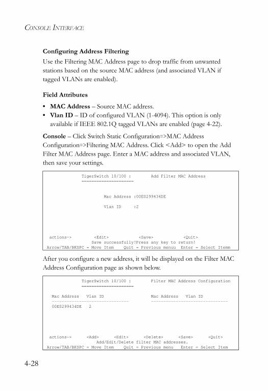
CONSOLE INTERFACE
Configuring Address FilteringUse the Filtering MAC Address page to drop traffic from unwanted stations based on the source MAC address (and associated VLAN if tagged VLANs are enabled).
Field Attributes
• MAC Address – Source MAC address.• Vlan ID – ID of configured VLAN (1-4094). This option is only
available if IEEE 802.1Q tagged VLANs are enabled (page 4-22).
Console – Click Switch Static Configuration=>MAC Address Configuration=>Filtering MAC Address. Click <Add> to open the Add Filter MAC Address page. Enter a MAC address and associated VLAN, then save your settings.
After you configure a new address, it will be displayed on the Filter MAC Address Configuration page as shown below.
TigerSwitch 10/100 : Add Filter MAC Address=====================
Mac Address :00E0299434DE
Vlan ID :2
actions-> <Edit> <Save> <Quit>Save successfully!Press any key to return!
Arrow/TAB/BKSPC = Move Item Quit = Previous menuu Enter = Select Itemm
TigerSwitch 10/100 : Filter MAC Address Configuration=====================
Mac Address Vlan ID Mac Address Vlan ID------------------------------- -------------------------------00E0299434DE 2
actions-> <Add> <Edit> <Delete> <Save> <Quit>Add/Edit/Delete filter MAC addresses.
Arrow/TAB/BKSPC = Move Item Quit = Previous menu Enter = Select Item
4-28
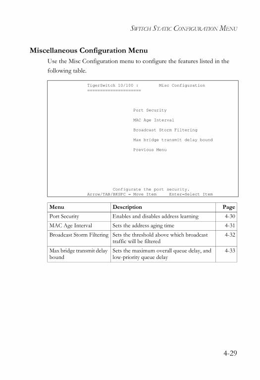
SWITCH STATIC CONFIGURATION MENU
Miscellaneous Configuration MenuUse the Misc Configuration menu to configure the features listed in the following table.
TigerSwitch 10/100 : Misc Configuration=====================
Port Security
MAC Age Interval
Broadcast Storm Filtering
Max bridge transmit delay bound
Previous Menu
Configurate the port security.Arrow/TAB/BKSPC = Move Item Enter=Select Item
Menu Description PagePort Security Enables and disables address learning 4-30MAC Age Interval Sets the address aging time 4-31Broadcast Storm Filtering Sets the threshold above which broadcast
traffic will be filtered4-32
Max bridge transmit delay bound
Sets the maximum overall queue delay, and low-priority queue delay
4-33
4-29
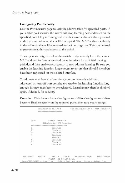
CONSOLE INTERFACE
Configuring Port SecurityUse the Port Security page to lock the address table for specified ports. If you enable port security, the switch will stop learning new addresses on the specified port. Only incoming traffic with source addresses already stored in the dynamic address table will be accepted. The MAC addresses already in the address table will be retained and will not age out. This can be used to prevent unauthorized access to the switch.
To use port security, first allow the switch to dynamically learn the source MAC address for frames received on an interface for an initial training period, and then enable port security to stop address learning. Be sure you enable the learning function long enough to ensure that all valid members have been registered on the selected interface.
To add new members at a later time, you can manually add static addresses, or turn off port security to reenable the learning function long enough for new members to be registered. Learning may then be disabled again, if desired, for security.
Console – Click Switch Static Configuration=>Misc Configuration=>Port Security. Enable security on the required ports, then save your settings.
TigerSwitch 10/100 : The Configuration of Port Security=====================
Port Enable Security(disable for MAC Learning)
-------------------------------1. Disabled2. Disabled3. Disabled4. Disabled5. enabled6. Disabled7. Disabled8. Disabled
actions-> <Quit> <Edit> <Save> <Previous Page> <Next Page>Select the Action menu.
Arrow/TAB/BKSPC = Move Item Quit = Previous menu Enter = Select Item
4-30
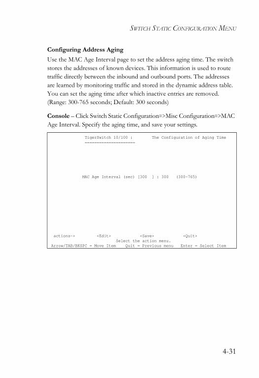
SWITCH STATIC CONFIGURATION MENU
Configuring Address AgingUse the MAC Age Interval page to set the address aging time. The switch stores the addresses of known devices. This information is used to route traffic directly between the inbound and outbound ports. The addresses are learned by monitoring traffic and stored in the dynamic address table. You can set the aging time after which inactive entries are removed. (Range: 300-765 seconds; Default: 300 seconds)
Console – Click Switch Static Configuration=>Misc Configuration=>MAC Age Interval. Specify the aging time, and save your settings.
TigerSwitch 10/100 : The Configuration of Aging Time=====================
MAC Age Interval (sec) [300 ] : 300 (300~765)
actions-> <Edit> <Save> <Quit>Select the action menu.
Arrow/TAB/BKSPC = Move Item Quit = Previous menu Enter = Select Item
4-31
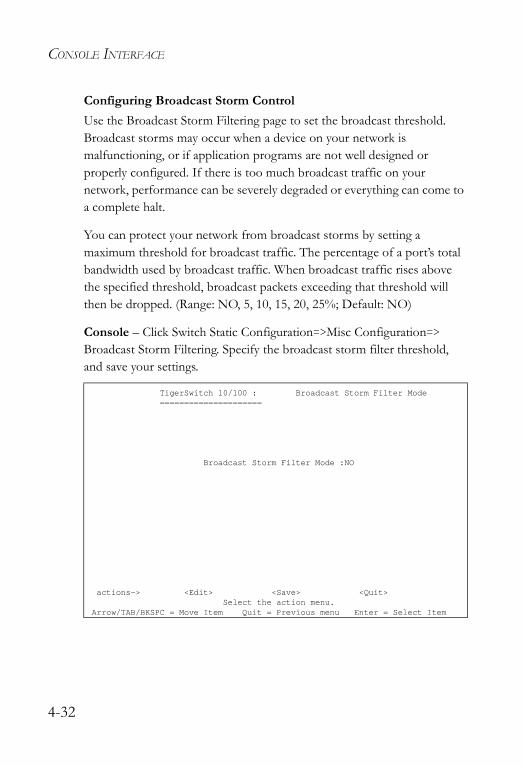
CONSOLE INTERFACE
Configuring Broadcast Storm ControlUse the Broadcast Storm Filtering page to set the broadcast threshold. Broadcast storms may occur when a device on your network is malfunctioning, or if application programs are not well designed or properly configured. If there is too much broadcast traffic on your network, performance can be severely degraded or everything can come to a complete halt.
You can protect your network from broadcast storms by setting a maximum threshold for broadcast traffic. The percentage of a port’s total bandwidth used by broadcast traffic. When broadcast traffic rises above the specified threshold, broadcast packets exceeding that threshold will then be dropped. (Range: NO, 5, 10, 15, 20, 25%; Default: NO)
Console – Click Switch Static Configuration=>Misc Configuration=> Broadcast Storm Filtering. Specify the broadcast storm filter threshold, and save your settings.
TigerSwitch 10/100 : Broadcast Storm Filter Mode=====================
Broadcast Storm Filter Mode :NO
actions-> <Edit> <Save> <Quit>Select the action menu.
Arrow/TAB/BKSPC = Move Item Quit = Previous menu Enter = Select Item
4-32
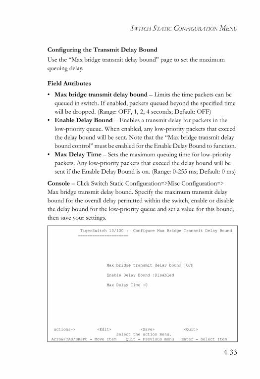
SWITCH STATIC CONFIGURATION MENU
Configuring the Transmit Delay BoundUse the “Max bridge transmit delay bound” page to set the maximum queuing delay.
Field Attributes
• Max bridge transmit delay bound – Limits the time packets can be queued in switch. If enabled, packets queued beyond the specified time will be dropped. (Range: OFF, 1, 2, 4 seconds; Default: OFF)
• Enable Delay Bound – Enables a transmit delay for packets in the low-priority queue. When enabled, any low-priority packets that exceed the delay bound will be sent. Note that the “Max bridge transmit delay bound control” must be enabled for the Enable Delay Bound to function.
• Max Delay Time – Sets the maximum queuing time for low-priority packets. Any low-priority packets that exceed the delay bound will be sent if the Enable Delay Bound is on. (Range: 0-255 ms; Default: 0 ms)
Console – Click Switch Static Configuration=>Misc Configuration=> Max bridge transmit delay bound. Specify the maximum transmit delay bound for the overall delay permitted within the switch, enable or disable the delay bound for the low-priority queue and set a value for this bound, then save your settings.
TigerSwitch 10/100 : Configure Max Bridge Transmit Delay Bound=====================
Max bridge transmit delay bound :OFF
Enable Delay Bound :Disabled
Max Delay Time :0
actions-> <Edit> <Save> <Quit>Select the action menu.
Arrow/TAB/BKSPC = Move Item Quit = Previous menu Enter = Select Item
4-33
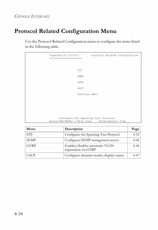
CONSOLE INTERFACE
Protocol Related Configuration MenuUse the Protocol Related Configuration menu to configure the items listed in the following table.
TigerSwitch 10/100 : Protocol Related Configuration=====================
STP
SNMP
GVRP
LACP
Previous Menu
Configure the Spanning Tree Protocol.Arrow/TAB/BKSPC = Move Item Enter=Select Item
Menu Description PageSTP Configures the Spanning Tree Protocol 4-35SNMP Configures SNMP management access 4-42GVRP Enables/disables automatic VLAN
registration via GVRP4-46
LACP Configures dynamic trunks; displays status 4-47
4-34
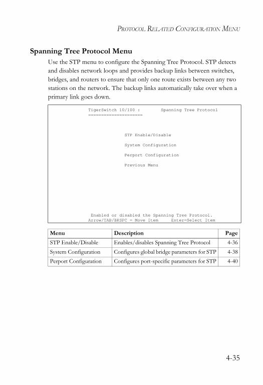
PROTOCOL RELATED CONFIGURATION MENU
Spanning Tree Protocol MenuUse the STP menu to configure the Spanning Tree Protocol. STP detects and disables network loops and provides backup links between switches, bridges, and routers to ensure that only one route exists between any two stations on the network. The backup links automatically take over when a primary link goes down.
TigerSwitch 10/100 : Spanning Tree Protocol=====================
STP Enable/Disable
System Configuration
Perport Configuration
Previous Menu
Enabled or disabled the Spanning Tree Protocol.Arrow/TAB/BKSPC = Move Item Enter=Select Item
Menu Description PageSTP Enable/Disable Enables/disables Spanning Tree Protocol 4-36System Configuration Configures global bridge parameters for STP 4-38Perport Configuration Configures port-specific parameters for STP 4-40
4-35
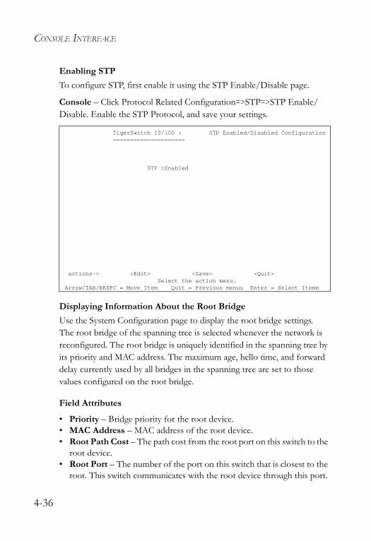
CONSOLE INTERFACE
Enabling STPTo configure STP, first enable it using the STP Enable/Disable page.
Console – Click Protocol Related Configuration=>STP=>STP Enable/Disable. Enable the STP Protocol, and save your settings.
Displaying Information About the Root BridgeUse the System Configuration page to display the root bridge settings. The root bridge of the spanning tree is selected whenever the network is reconfigured. The root bridge is uniquely identified in the spanning tree by its priority and MAC address. The maximum age, hello time, and forward delay currently used by all bridges in the spanning tree are set to those values configured on the root bridge.
Field Attributes
• Priority – Bridge priority for the root device.• MAC Address – MAC address of the root device.• Root Path Cost – The path cost from the root port on this switch to the
root device.• Root Port – The number of the port on this switch that is closest to the
root. This switch communicates with the root device through this port.
TigerSwitch 10/100 : STP Enabled/Disabled Configuration=====================
STP :Enabled
actions-> <Edit> <Save> <Quit>Select the action menu.
Arrow/TAB/BKSPC = Move Item Quit = Previous menuu Enter = Select Itemm
4-36
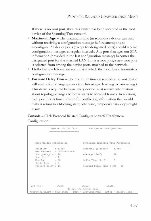
PROTOCOL RELATED CONFIGURATION MENU
If there is no root port, then this switch has been accepted as the root device of the Spanning Tree network.
• Maximum Age – The maximum time (in seconds) a device can wait without receiving a configuration message before attempting to reconfigure. All device ports (except for designated ports) should receive configuration messages at regular intervals. Any port that ages out STA information (provided in the last configuration message) becomes the designated port for the attached LAN. If it is a root port, a new root port is selected from among the device ports attached to the network.
• Hello Time – Interval (in seconds) at which the root device transmits a configuration message.
• Forward Delay Time – The maximum time (in seconds) the root device will wait before changing states (i.e., listening to learning to forwarding.) This delay is required because every device must receive information about topology changes before it starts to forward frames. In addition, each port needs time to listen for conflicting information that would make it return to a blocking state; otherwise, temporary data loops might result.
Console – Click Protocol Related Configuration=>STP=>System Configuration.
TigerSwitch 10/100 : STP System Configuration=====================
Root Bridge Information Configure Spanning Tree Parameters------------------------ -----------------------------------Priority : 32768 Priority (1-65535) :32768Mac Address : 0000ABCD0000Root_Path_Cost: 10 Max Age (6-40) :20Root Port : 2Max Age : 20 Hello Time (1-10) :2Hello Time : 2Forward Delay : 15 Forward_Delay_Time(4-30) :15
actions-> <Edit> <Save> <Quit>Select the action menu.
Arrow/TAB/BKSPC = Move Item Quit = Previous menu Enter = Select Item
4-37
CONSOLE INTERFACE
Configuring Global STP SettingsUse the System Configuration page to configure global settings for STP which apply to the entire switch.
Field Attributes
• Priority – Bridge priority is used in selecting the root device, root port, and designated port. The device with the highest priority becomes the STA root device. However, if all devices have the same priority, the device with the lowest MAC address will then become the root device. (Note that lower numeric values indicate higher priority.)- Default: 32768- Range: 0 - 65535
• Maximum Age – The maximum time (in seconds) a device can wait without receiving a configuration message before attempting to reconfigure. All device ports (except for designated ports) should receive configuration messages at regular intervals. Any port that ages out STA information (provided in the last configuration message) becomes the designated port for the attached LAN. If it is a root port, a new root port is selected from among the device ports attached to the network. - Default: 20- Minimum: The higher of 6 or [2 x (Hello Time + 1)]- Maximum: The lower of 40 or [2 x (Forward Delay - 1)]
• Hello Time – Interval (in seconds) at which the root device transmits a configuration message. - Default: 2- Minimum: 1 - Maximum: The lower of 10 or [(Max. Message Age / 2) -1]
4-38
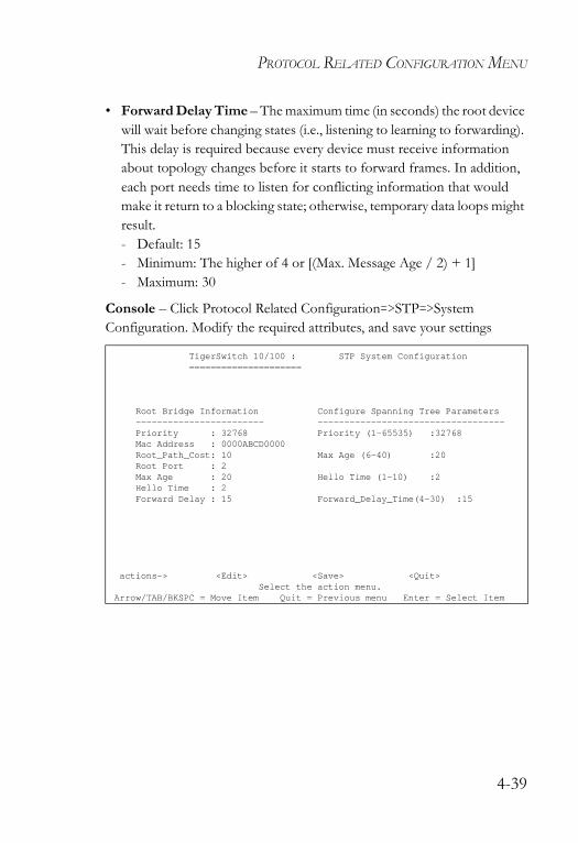
PROTOCOL RELATED CONFIGURATION MENU
• Forward Delay Time – The maximum time (in seconds) the root device will wait before changing states (i.e., listening to learning to forwarding). This delay is required because every device must receive information about topology changes before it starts to forward frames. In addition, each port needs time to listen for conflicting information that would make it return to a blocking state; otherwise, temporary data loops might result.- Default: 15- Minimum: The higher of 4 or [(Max. Message Age / 2) + 1]- Maximum: 30
Console – Click Protocol Related Configuration=>STP=>System Configuration. Modify the required attributes, and save your settings
TigerSwitch 10/100 : STP System Configuration=====================
Root Bridge Information Configure Spanning Tree Parameters------------------------ -----------------------------------Priority : 32768 Priority (1-65535) :32768Mac Address : 0000ABCD0000Root_Path_Cost: 10 Max Age (6-40) :20Root Port : 2Max Age : 20 Hello Time (1-10) :2Hello Time : 2Forward Delay : 15 Forward_Delay_Time(4-30) :15
actions-> <Edit> <Save> <Quit>Select the action menu.
Arrow/TAB/BKSPC = Move Item Quit = Previous menu Enter = Select Item
4-39
CONSOLE INTERFACE
Configuring Port STP SettingsUse the Perport Configuration page to set STA attributes for specific ports, including port priority and path cost. You can use a different priority or path cost for ports of the same media type to indicate the preferred path.
Field Attributes
• Priority – Defines the priority used for this port in the Spanning Tree Protocol. If the path cost for all ports on a switch are the same, the port with the highest priority (i.e., lowest value) will be configured as an active link in the Spanning Tree. This makes a port with higher priority less likely to be blocked if the Spanning Tree Protocol is detecting network loops. Where more than one port is assigned the highest priority, the port with lowest numeric identifier will be enabled.- Default: 128- Range: 0 - 255
• Path Cost – This parameter is used by the STP to determine the best path between devices. Therefore, lower values should be assigned to ports attached to faster media, and higher values assigned to ports with slower media. (Path cost takes precedence over port priority.) • Full Range: 1-65535• Recommended Range –
- Ethernet: 50-600- Fast Ethernet: 10-60- Gigabit Ethernet: 3-10
• Defaults –- Ethernet – half duplex: 100; full duplex: 95; trunk: 90- Fast Ethernet – half duplex: 19; full duplex: 18; trunk: 15- Gigabit Ethernet – full duplex: 4
4-40
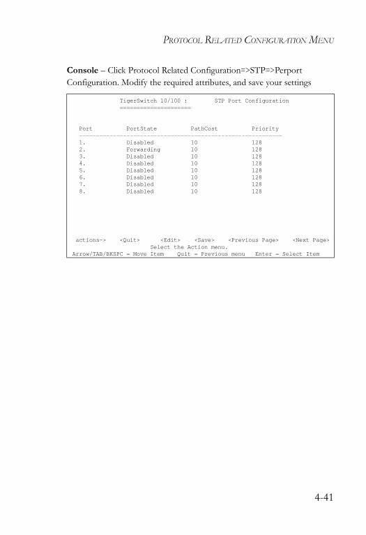
PROTOCOL RELATED CONFIGURATION MENU
Console – Click Protocol Related Configuration=>STP=>Perport Configuration. Modify the required attributes, and save your settings
TigerSwitch 10/100 : STP Port Configuration=====================
Port PortState PathCost Priority------------------------------------------------------------1. Disabled 10 1282. Forwarding 10 1283. Disabled 10 1284. Disabled 10 1285. Disabled 10 1286. Disabled 10 1287. Disabled 10 1288. Disabled 10 128
actions-> <Quit> <Edit> <Save> <Previous Page> <Next Page>Select the Action menu.
Arrow/TAB/BKSPC = Move Item Quit = Previous menu Enter = Select Item
4-41
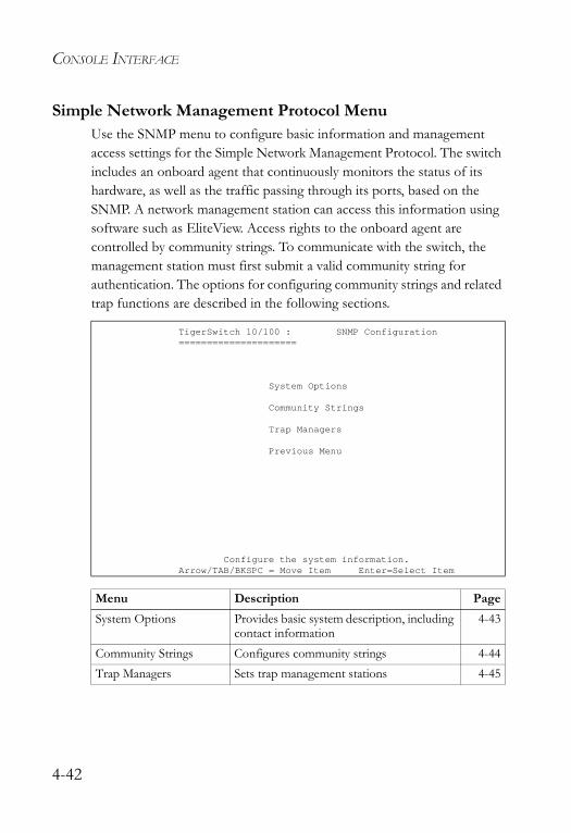
CONSOLE INTERFACE
Simple Network Management Protocol MenuUse the SNMP menu to configure basic information and management access settings for the Simple Network Management Protocol. The switch includes an onboard agent that continuously monitors the status of its hardware, as well as the traffic passing through its ports, based on the SNMP. A network management station can access this information using software such as EliteView. Access rights to the onboard agent are controlled by community strings. To communicate with the switch, the management station must first submit a valid community string for authentication. The options for configuring community strings and related trap functions are described in the following sections.
TigerSwitch 10/100 : SNMP Configuration=====================
System Options
Community Strings
Trap Managers
Previous Menu
Configure the system information.Arrow/TAB/BKSPC = Move Item Enter=Select Item
Menu Description PageSystem Options Provides basic system description, including
contact information4-43
Community Strings Configures community strings 4-44Trap Managers Sets trap management stations 4-45
4-42
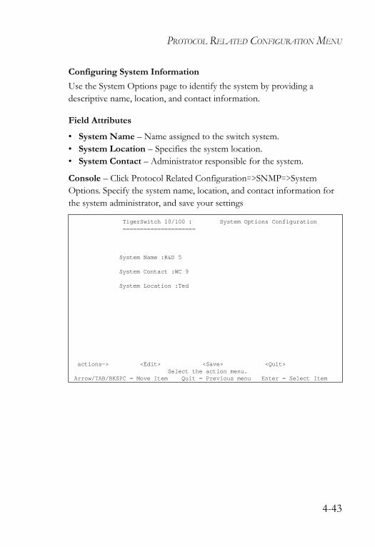
PROTOCOL RELATED CONFIGURATION MENU
Configuring System InformationUse the System Options page to identify the system by providing a descriptive name, location, and contact information.
Field Attributes
• System Name – Name assigned to the switch system.• System Location – Specifies the system location. • System Contact – Administrator responsible for the system.
Console – Click Protocol Related Configuration=>SNMP=>System Options. Specify the system name, location, and contact information for the system administrator, and save your settings
TigerSwitch 10/100 : System Options Configuration=====================
System Name :R&D 5
System Contact :WC 9
System Location :Ted
actions-> <Edit> <Save> <Quit>Select the action menu.
Arrow/TAB/BKSPC = Move Item Quit = Previous menu Enter = Select Item
4-43
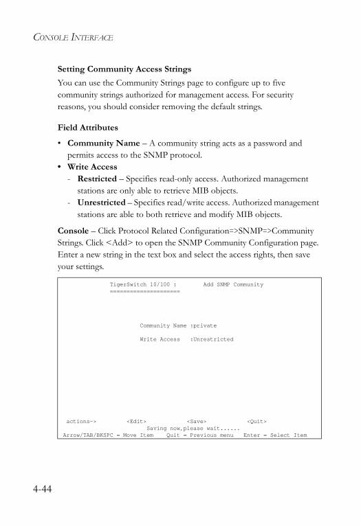
CONSOLE INTERFACE
Setting Community Access Strings You can use the Community Strings page to configure up to five community strings authorized for management access. For security reasons, you should consider removing the default strings.
Field Attributes
• Community Name – A community string acts as a password and permits access to the SNMP protocol.
• Write Access - Restricted – Specifies read-only access. Authorized management
stations are only able to retrieve MIB objects. - Unrestricted – Specifies read/write access. Authorized management
stations are able to both retrieve and modify MIB objects.
Console – Click Protocol Related Configuration=>SNMP=>Community Strings. Click <Add> to open the SNMP Community Configuration page. Enter a new string in the text box and select the access rights, then save your settings.
TigerSwitch 10/100 : Add SNMP Community=====================
Community Name :private
Write Access :Unrestricted
actions-> <Edit> <Save> <Quit>Saving now,please wait......
Arrow/TAB/BKSPC = Move Item Quit = Previous menu Enter = Select Item
4-44
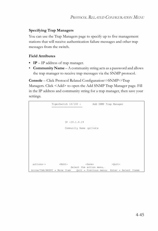
PROTOCOL RELATED CONFIGURATION MENU
Specifying Trap Managers You can use the Trap Managers page to specify up to five management stations that will receive authentication failure messages and other trap messages from the switch.
Field Attributes
• IP – IP address of trap manager.• Community Name – A community string acts as a password and allows
the trap manager to receive trap messages via the SNMP protocol.
Console – Click Protocol Related Configuration=>SNMP=>Trap Managers. Click <Add> to open the Add SNMP Trap Manager page. Fill in the IP address and community string for a trap manager, then save your settings.
TigerSwitch 10/100 : Add SNMP Trap Manager=====================
IP :10.1.0.19
Community Name :private
actions-> <Edit> <Save> <Quit>Select the action menu.
Arrow/TAB/BKSPC = Move Item Quit = Previous menuu Enter = Select Itemm
4-45
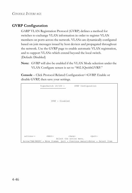
CONSOLE INTERFACE
GVRP ConfigurationGARP VLAN Registration Protocol (GVRP) defines a method for switches to exchange VLAN information in order to register VLAN members on ports across the network. VLANs are dynamically configured based on join messages issued by host devices and propagated throughout the network. Use the GVRP page to enable automatic VLAN registration, and to support VLANs which extend beyond the local switch. (Default: Disabled)
Note: GVRP will also be enabled if the VLAN Mode selection under the VLAN Configure screen is set to “802.1QwithGVRP.”
Console – Click Protocol Related Configuration=>GVRP. Enable or disable GVRP, then save your settings.
TigerSwitch 10/100 : GVRP Configuration=====================
GVRP : Disabled
actions-> <Edit> <Save> <Quit>Select the action menu.
Arrow/TAB/BKSPC = Move Itemem Quit = Previous menurl+Enter = Select Item
4-46
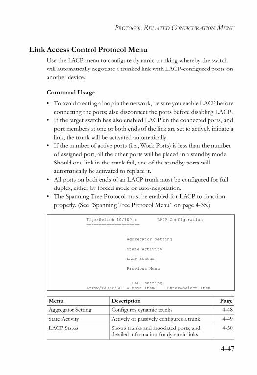
PROTOCOL RELATED CONFIGURATION MENU
Link Access Control Protocol MenuUse the LACP menu to configure dynamic trunking whereby the switch will automatically negotiate a trunked link with LACP-configured ports on another device.
Command Usage
• To avoid creating a loop in the network, be sure you enable LACP before connecting the ports; also disconnect the ports before disabling LACP.
• If the target switch has also enabled LACP on the connected ports, and port members at one or both ends of the link are set to actively initiate a link, the trunk will be activated automatically.
• If the number of active ports (i.e., Work Ports) is less than the number of assigned port, all the other ports will be placed in a standby mode. Should one link in the trunk fail, one of the standby ports will automatically be activated to replace it.
• All ports on both ends of an LACP trunk must be configured for full duplex, either by forced mode or auto-negotiation.
• The Spanning Tree Protocol must be enabled for LACP to function properly. (See “Spanning Tree Protocol Menu” on page 4-35.)
TigerSwitch 10/100 : LACP Configuration=====================
Aggregator Setting
State Activity
LACP Status
Previous Menu
LACP setting.Arrow/TAB/BKSPC = Move Item Enter=Select Item
Menu Description PageAggregator Setting Configures dynamic trunks 4-48State Activity Actively or passively configures a trunk 4-49LACP Status Shows trunks and associated ports, and
detailed information for dynamic links4-50
4-47
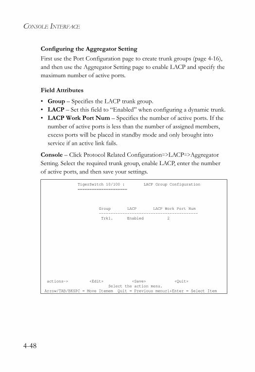
CONSOLE INTERFACE
Configuring the Aggregator SettingFirst use the Port Configuration page to create trunk groups (page 4-16), and then use the Aggregator Setting page to enable LACP and specify the maximum number of active ports.
Field Attributes
• Group – Specifies the LACP trunk group. • LACP – Set this field to “Enabled” when configuring a dynamic trunk.• LACP Work Port Num – Specifies the number of active ports. If the
number of active ports is less than the number of assigned members, excess ports will be placed in standby mode and only brought into service if an active link fails.
Console – Click Protocol Related Configuration=>LACP=>Aggregator Setting. Select the required trunk group, enable LACP, enter the number of active ports, and then save your settings.
TigerSwitch 10/100 : LACP Group Configuration=====================
Group LACP LACP Work Port Num------------------------------------------Trk1. Enabled 2
actions-> <Edit> <Save> <Quit>Select the action menu.
Arrow/TAB/BKSPC = Move Itemem Quit = Previous menurl+Enter = Select Item
4-48
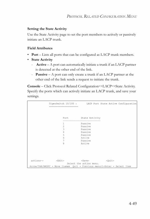
PROTOCOL RELATED CONFIGURATION MENU
Setting the State Activity Use the State Activity page to set the port members to actively or passively initiate an LACP trunk.
Field Attributes
• Port – Lists all ports that can be configured as LACP trunk members.• State Activity
- Active – A port can automatically initiate a trunk if an LACP partner is detected at the other end of the link.
- Passive – A port can only create a trunk if an LACP partner at the other end of the link sends a request to initiate the trunk.
Console – Click Protocol Related Configuration=>LACP=>State Activity. Specify the ports which can actively initiate an LACP trunk, and save your settings.
TigerSwitch 10/100 : LACP Port State Active Configuration=====================
Port State Activity---------------------------1 Passive2 Passive3 Passive4 Passive5 Passive6 Active7 Passive8 Active
actions-> <Edit> <Save> <Quit>Select the action menu.
Arrow/TAB/BKSPC = Move Itemem Quit = Previous menurl+Enter = Select Item
4-49
CONSOLE INTERFACE
Displaying Aggregator InformationUse the LACP Status page to show trunks and associated ports, and to display detailed information for dynamic links.
Field Attributes
Static Trunks• Group Key – Displays static trunks.• Port No – The port members assigned to the trunk.
Dynamic Trunks• Actor – The device that initiated the trunk.• Partner – The device that responded to a link initialization request.• Priority – The priority used to select the device that initiates the trunk if
both ends of the link are set to the LACP State of “Active.” This is the same as the System Priority on the Aggregator Setting page.
• MAC – The physical address of the devices at both ends of the link.• Port No – Active port members. (Other ports may be in standby mode.)• Key – Only one dynamic trunk can be activated between two devices, so
a key is sent to the partner device to uniquely identify each trunk. A trunk can only be formed if the devices at both ends of a link use the same key. A key is automatically generated by the switch when configuring a trunk.
• Active – Indicates whether a port has been set to actively initiate a trunk when an LACP partner is detected at the other end of the link. This field is configured in the State Activity page.
4-50
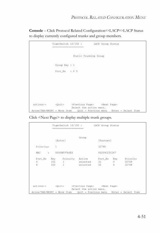
PROTOCOL RELATED CONFIGURATION MENU
Console – Click Protocol Related Configuration=>LACP=>LACP Status to display currently configured trunks and group members.
Click <Next Page> to display multiple trunk groups.
TigerSwitch 10/100 : LACP Group Status=====================
Static Trunking Group
Group Key : 1
Port_No : 4 5
actions-> <Quit> <Previous Page> <Next Page>Select the action menu.
Arrow/TAB/BKSPC = Move Item Quit = Previous menu Enter = Select Item
TigerSwitch 10/100 : LACP Group Status=====================
Group[Actor] [Partner]
Priority: 1 32768
MAC : 0050BF97A4E0 00209C23C267
Port_No Key Priority Active Port_No Key Priority6 102 1 selected 31 4 327688 102 1 selected 32 4 32768
actions-> <Quit> <Previous Page> <Next Page>Select the action menu.
Arrow/TAB/BKSPC = Move Item Quit = Previous menu Enter = Select Item
4-51
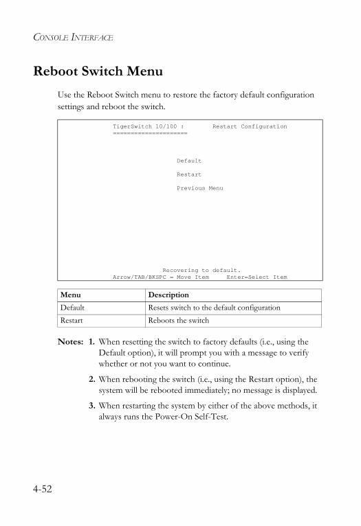
CONSOLE INTERFACE
Reboot Switch Menu Use the Reboot Switch menu to restore the factory default configuration settings and reboot the switch.
Notes: 1. When resetting the switch to factory defaults (i.e., using the Default option), it will prompt you with a message to verify whether or not you want to continue.
2. When rebooting the switch (i.e., using the Restart option), the system will be rebooted immediately; no message is displayed.
3. When restarting the system by either of the above methods, it always runs the Power-On Self-Test.
TigerSwitch 10/100 : Restart Configuration=====================
Default
Restart
Previous Menu
Recovering to default.Arrow/TAB/BKSPC = Move Item Enter=Select Item
Menu DescriptionDefault Resets switch to the default configurationRestart Reboots the switch
4-52

SET LOGOUT TIMER MENU
Set Logout Timer MenuUse the Set Logout Timer menu to set the timeout for detecting keyboard input before terminating the current console session. The default is 120 seconds, and the range is 5-960 seconds.
Note: The value of the logout timer is not saved in non-volatile memory. This timer is reset to the factory default when you reboot the switch.
TigerSwitch 10/100 : Logout Timer Configuration.=====================
Logout's Timer : 120 (5~960 Sec)
actions-> <Edit> <Save> <Quit>Select the action menu.
Arrow/TAB/BKSPC = Move Item Quit = Previous menuu Enter = Select Item
4-53

CONSOLE INTERFACE
4-54
CHAPTER 5COMMAND LINE INTERFACE
This chapter provides a basic description of the command line interface. For a more detailed description about specific features, please refer to the appropriate section in Chapter 3, Configuring the Switch.
Accessing the CLIThe switch can be managed by entering a sequence of command keywords and parameters. Using the switch’s command-line interface (CLI) is very similar to entering commands on a UNIX system. To use the CLI, choose Command Line in the console’s main menu, and then enter any of the commands described in this chapter.
Entering CommandsThis section describes how to enter CLI commands.
Keywords and ArgumentsA CLI command is a series of keywords and arguments. Keywords identify a command, and arguments specify configuration parameters. For example, in the command “show portstatus 1,” show and portstatus are keywords, and 1 is an argument that specifies the port.
5-1
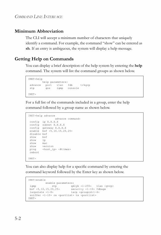
COMMAND LINE INTERFACE
Minimum AbbreviationThe CLI will accept a minimum number of characters that uniquely identify a command. For example, the command “show” can be entered as sh. If an entry is ambiguous, the system will display a help message.
Getting Help on CommandsYou can display a brief description of the help system by entering the help command. The system will list the command groups as shown below.
For a full list of the commands included in a group, enter the help command followed by a group name as shown below.
You can also display help for a specific command by entering the command keyword followed by the Enter key as shown below.
INET>helphelp parameters:
advance port vlan fdb trkgrpstp qos igmp console
INET>
INET>help advanceadvance command:
config ip X.X.X.Xconfig subnet X.X.X.Xconfig gateway X.X.X.Xenable bsf <5,10,15,20,25>disable bsfshow bsfshow ipshow macshow versionping <host_ip> <#times>reboot
INET>
INET>enableenable parameters:
igmp stp qdlyb <1-255> vlan {gvrp}bsf <5,10,15,20,25> security <1-10> fdbagelacpstate <1-8> lacp <groupid:1~4>sniffer <1-10> rx <portlist> tx <portlist>INET>
5-2
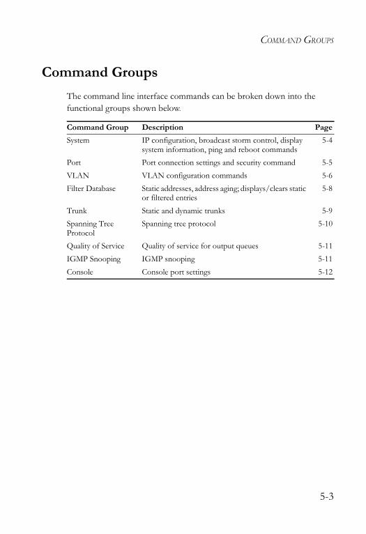
COMMAND GROUPS
Command GroupsThe command line interface commands can be broken down into the functional groups shown below.
Command Group Description PageSystem IP configuration, broadcast storm control, display
system information, ping and reboot commands5-4
Port Port connection settings and security command 5-5VLAN VLAN configuration commands 5-6Filter Database Static addresses, address aging; displays/clears static
or filtered entries5-8
Trunk Static and dynamic trunks 5-9Spanning Tree Protocol
Spanning tree protocol 5-10
Quality of Service Quality of service for output queues 5-11IGMP Snooping IGMP snooping 5-11Console Console port settings 5-12
5-3
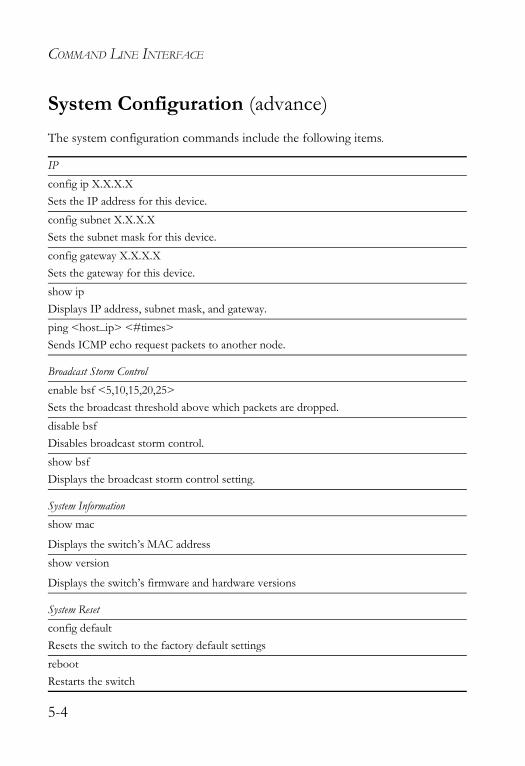
COMMAND LINE INTERFACE
System Configuration (advance)The system configuration commands include the following items.
IP config ip X.X.X.XSets the IP address for this device.config subnet X.X.X.XSets the subnet mask for this device.config gateway X.X.X.XSets the gateway for this device.show ipDisplays IP address, subnet mask, and gateway.ping <host_ip> <#times>Sends ICMP echo request packets to another node.
Broadcast Storm Controlenable bsf <5,10,15,20,25>Sets the broadcast threshold above which packets are dropped. disable bsfDisables broadcast storm control. show bsfDisplays the broadcast storm control setting.
System Informationshow mac
Displays the switch’s MAC address show version
Displays the switch’s firmware and hardware versions
System Resetconfig defaultResets the switch to the factory default settingsrebootRestarts the switch
5-4
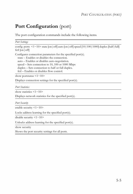
PORT CONFIGURATION (PORT)
Port Configuration (port)The port configuration commands include the following items.
Port Settingsconfig ports <1~10> state [on|off] auto [on|off] speed [10|100|1000] duplex [half|full] fctl [on|off]Configures connection parameters for the specified port(s).
state – Enables or disables the connection.auto – Enables or disables auto-negotiation.speed – Sets connection to 10, 100 or 1000 Mbpsduplex – Sets connection to half or full duplex.fctl – Enables or disables flow control.
show portstatus <1~10>Displays connection settings for the specified port(s).
Port Statisticsshow statistics <1~10>Displays network statistics for the specified port(s).
Port Securityenable security <1~10>
Locks address learning for the specified port(s).disable security <1~10>
Unlocks address learning for the specified port(s).show securityShows the port security settings for all ports.
5-5
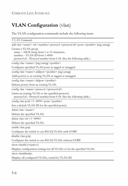
COMMAND LINE INTERFACE
VLAN Configuration (vlan)The VLAN configuration commands include the following items.
VLAN Commandsadd vlan <name> vid <number> protocol <protocol id> ports <portlist> [tag|untag]Creates a VLAN group.
name – ASCII string from 1 to 15 characters.number – VLAN ID from 1-4094.protocol id – Protocol number from 0-18. (See the following table.)
config vlan <name> [tag|untag] <portlist>Configures specified VLAN ports as tagged or untagged.config vlan <name> addport <portlist> [tag|untag]Adds port(s) to an existing VLAN as tagged or untagged.config vlan <name> delport <portlist>Deletes port(s) from an existing VLAN.config vlan <name> protocol <protocol id>Limits an existing VLAN to the specified protocol.
protocol id – Protocol number from 0-18. (See the following table.)config vlan pvid <1~4094> ports <portlist>Sets a default VLAN ID for the specified port(s).delete vlan <name>Deletes the specified VLAN.delete vlan vid <1~4094>Deletes the specified VLAN.enable vlan gvrpConfigures the switch to use 802.1Q VLANs with GVRP.disable vlan gvrpConfigures the switch to use 802.1Q VLANs without GVRP.show vlantbl [<name>]Displays configuration settings for all VLANs or for the specified VLAN.show vlantblindexDisplays all configured VLANs, sorted by VLAN ID.
5-6
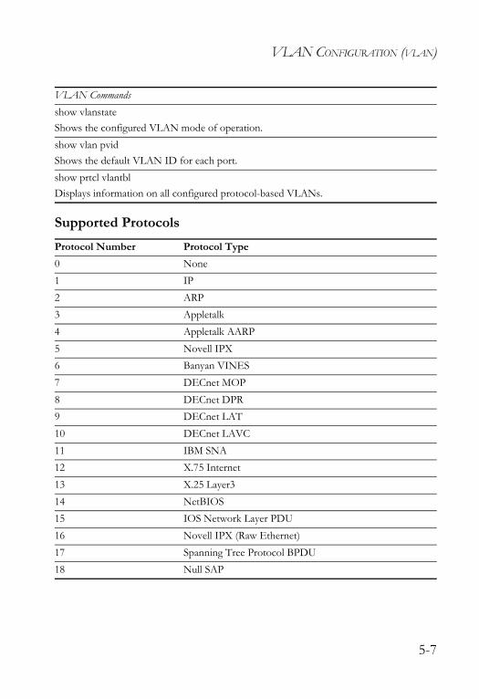
VLAN CONFIGURATION (VLAN)
Supported Protocols
show vlanstateShows the configured VLAN mode of operation.show vlan pvidShows the default VLAN ID for each port.show prtcl vlantblDisplays information on all configured protocol-based VLANs.
Protocol Number Protocol Type0 None1 IP2 ARP3 Appletalk4 Appletalk AARP5 Novell IPX6 Banyan VINES7 DECnet MOP8 DECnet DPR9 DECnet LAT10 DECnet LAVC11 IBM SNA12 X.75 Internet13 X.25 Layer314 NetBIOS15 IOS Network Layer PDU16 Novell IPX (Raw Ethernet)17 Spanning Tree Protocol BPDU18 Null SAP
VLAN Commands
5-7
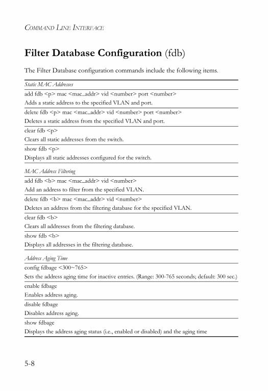
COMMAND LINE INTERFACE
Filter Database Configuration (fdb)The Filter Database configuration commands include the following items.
Static MAC Addressesadd fdb <p> mac <mac_addr> vid <number> port <number>Adds a static address to the specified VLAN and port.delete fdb <p> mac <mac_addr> vid <number> port <number>Deletes a static address from the specified VLAN and port.clear fdb <p>Clears all static addresses from the switch.show fdb <p>Displays all static addresses configured for the switch.
MAC Address Filteringadd fdb <b> mac <mac_addr> vid <number>Add an address to filter from the specified VLAN.delete fdb <b> mac <mac_addr> vid <number>Deletes an address from the filtering database for the specified VLAN.clear fdb <b>Clears all addresses from the filtering database.show fdb <b>Displays all addresses in the filtering database.
Address Aging Timeconfig fdbage <300~765>Sets the address aging time for inactive entries. (Range: 300-765 seconds; default: 300 sec.)enable fdbageEnables address aging.disable fdbageDisables address aging.show fdbageDisplays the address aging status (i.e., enabled or disabled) and the aging time
5-8
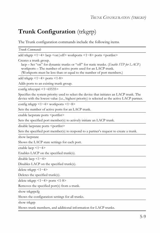
TRUNK CONFIGURATION (TRKGRP)
Trunk Configuration (trkgrp)The Trunk configuration commands include the following items.
Trunk Commandsadd trkgrp <1~4> lacp <on|off> workports <1~8> ports <portlist>Creates a trunk group.
lacp – Set “on” for dynamic trunks or “off” for static trunks. (Enable STP for LACP.)workports – The number of active ports used for an LACP trunk. (Workports must be less than or equal to the number of port members.)
add trkgrp <1~4> ports <1-8>Adds ports to an existing trunk group.config trksyspri <1~65535>Specifies the system priority used to select the device that initiates an LACP trunk. The device with the lowest value (i.e., highest priority) is selected as the active LACP partner.config trkgrp <1~4> workports <1~8>Sets the number of active ports for an LACP trunk.enable lacpstate ports <portlist>Sets the specified port member(s) to actively initiate an LACP trunk.disable lacpstate ports <portlist>Sets the specified port member(s) to respond to a partner’s request to create a trunk.show lacpstateShows the LACP state settings for each port.enable lacp <1~4>Enables LACP on the specified trunk(s).disable lacp <1~4>Disables LACP on the specified trunk(s).delete trkgrp <1~4>Deletes the specified trunk(s).delete trkgrp <1~4> ports <1-8>Removes the specified port(s) from a trunk.show trkgrpcfgShows the configuration settings for all trunks.show trkgrpShows trunk members, and additional information for LACP trunks.
5-9
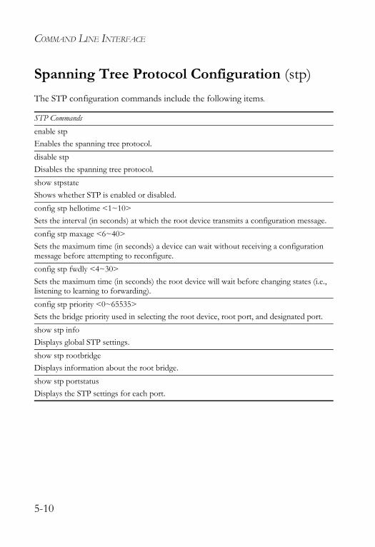
COMMAND LINE INTERFACE
Spanning Tree Protocol Configuration (stp)The STP configuration commands include the following items.
STP Commandsenable stpEnables the spanning tree protocol.disable stpDisables the spanning tree protocol.show stpstateShows whether STP is enabled or disabled.config stp hellotime <1~10>Sets the interval (in seconds) at which the root device transmits a configuration message. config stp maxage <6~40>Sets the maximum time (in seconds) a device can wait without receiving a configuration message before attempting to reconfigure. config stp fwdly <4~30>Sets the maximum time (in seconds) the root device will wait before changing states (i.e., listening to learning to forwarding).config stp priority <0~65535>Sets the bridge priority used in selecting the root device, root port, and designated port. show stp infoDisplays global STP settings.show stp rootbridgeDisplays information about the root bridge.show stp portstatusDisplays the STP settings for each port.
5-10
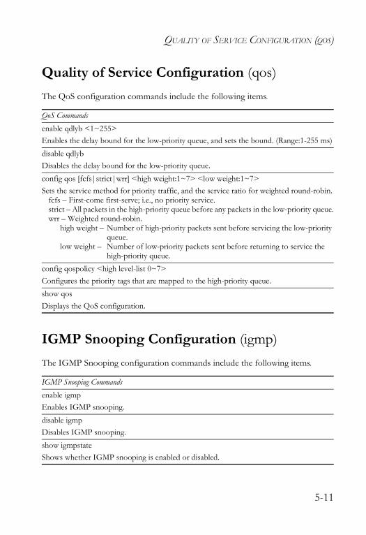
QUALITY OF SERVICE CONFIGURATION (QOS)
Quality of Service Configuration (qos)The QoS configuration commands include the following items.
IGMP Snooping Configuration (igmp)The IGMP Snooping configuration commands include the following items.
QoS Commandsenable qdlyb <1~255>Enables the delay bound for the low-priority queue, and sets the bound. (Range:1-255 ms)disable qdlybDisables the delay bound for the low-priority queue.config qos [fcfs|strict|wrr] <high weight:1~7> <low weight:1~7>Sets the service method for priority traffic, and the service ratio for weighted round-robin.
fcfs – First-come first-serve; i.e., no priority service.strict – All packets in the high-priority queue before any packets in the low-priority queue.wrr – Weighted round-robin.
high weight – Number of high-priority packets sent before servicing the low-priority queue.
low weight – Number of low-priority packets sent before returning to service the high-priority queue.
config qospolicy <high level-list 0~7>Configures the priority tags that are mapped to the high-priority queue.show qosDisplays the QoS configuration.
IGMP Snooping Commandsenable igmpEnables IGMP snooping.disable igmpDisables IGMP snooping.show igmpstateShows whether IGMP snooping is enabled or disabled.
5-11

COMMAND LINE INTERFACE
Console Configuration (console)The console configuration commands include the following items.
Console Commandsshow consoleDisplays the connection settings for the console port.
5-12
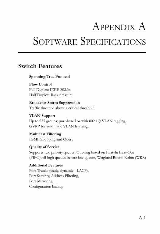
APPENDIX ASOFTWARE SPECIFICATIONS
Switch FeaturesSpanning Tree Protocol
Flow ControlFull Duplex: IEEE 802.3xHalf Duplex: Back pressure
Broadcast Storm Suppression Traffic throttled above a critical threshold
VLAN SupportUp to 255 groups; port-based or with 802.1Q VLAN tagging,GVRP for automatic VLAN learning,
Multicast Filtering IGMP Snooping and Query
Quality of ServiceSupports two priority queues, Queuing based on First-In First-Out (FIFO), all high queues before low queues, Weighted Round Robin (WRR)
Additional FeaturesPort Trunks (static, dynamic - LACP), Port Security, Address Filtering, Port Mirroring, Configuration backup
A-1
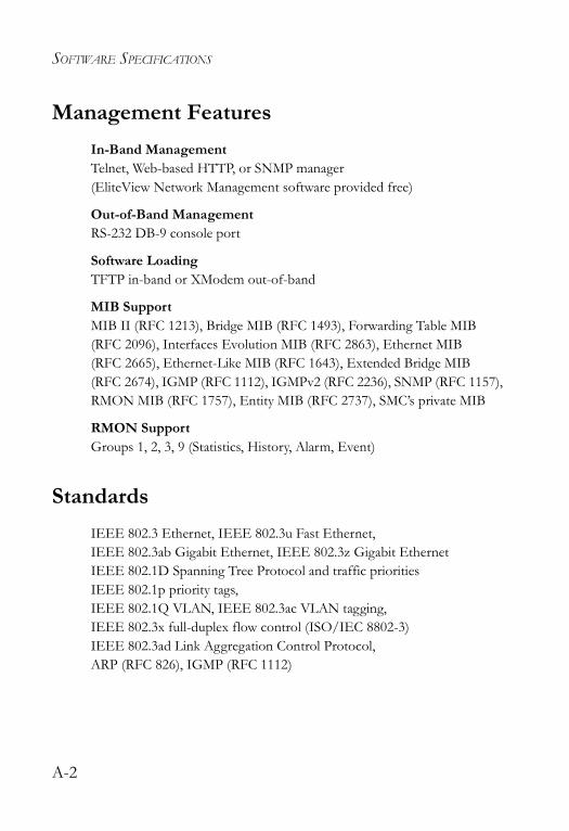
SOFTWARE SPECIFICATIONS
Management FeaturesIn-Band ManagementTelnet, Web-based HTTP, or SNMP manager(EliteView Network Management software provided free)
Out-of-Band ManagementRS-232 DB-9 console port
Software LoadingTFTP in-band or XModem out-of-band
MIB SupportMIB II (RFC 1213), Bridge MIB (RFC 1493), Forwarding Table MIB (RFC 2096), Interfaces Evolution MIB (RFC 2863), Ethernet MIB (RFC 2665), Ethernet-Like MIB (RFC 1643), Extended Bridge MIB (RFC 2674), IGMP (RFC 1112), IGMPv2 (RFC 2236), SNMP (RFC 1157), RMON MIB (RFC 1757), Entity MIB (RFC 2737), SMC’s private MIB
RMON SupportGroups 1, 2, 3, 9 (Statistics, History, Alarm, Event)
StandardsIEEE 802.3 Ethernet, IEEE 802.3u Fast Ethernet, IEEE 802.3ab Gigabit Ethernet, IEEE 802.3z Gigabit EthernetIEEE 802.1D Spanning Tree Protocol and traffic prioritiesIEEE 802.1p priority tags, IEEE 802.1Q VLAN, IEEE 802.3ac VLAN tagging,IEEE 802.3x full-duplex flow control (ISO/IEC 8802-3)IEEE 802.3ad Link Aggregation Control Protocol, ARP (RFC 826), IGMP (RFC 1112)
A-2
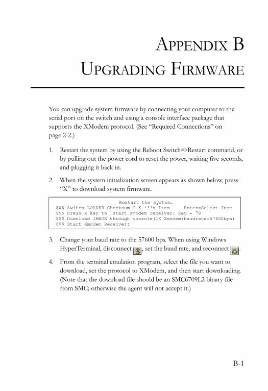
APPENDIX BUPGRADING FIRMWARE
You can upgrade system firmware by connecting your computer to the serial port on the switch and using a console interface package that supports the XModem protocol. (See “Required Connections” on page 2-2.)
1. Restart the system by using the Reboot Switch=>Restart command, or by pulling out the power cord to reset the power, waiting five seconds, and plugging it back in.
2. When the system initialization screen appears as shown below, press “X” to download system firmware.
3. Change your baud rate to the 57600 bps. When using Windows HyperTerminal, disconnect , set the baud rate, and reconnect .
4. From the terminal emulation program, select the file you want to download, set the protocol to XModem, and then start downloading. (Note that the download file should be an SMC6709L2 binary file from SMC; otherwise the agent will not accept it.)
Restart the system.$$$ Switch LOADER Checksum O.K !!!s Item Enter=Select Item$$$ Press X key to start Xmodem receiver: Key = 78$$$ Download IMAGE through console(1K Xmodem;baudrate=57600bps)$$$ Start Xmodem Receiver:
B-1

UPGRADING FIRMWARE
5. After the file has been downloaded, the console screen will display information similar to that shown below.
Change the baud rate back to 9600 bps. When using Windows HyperTerminal, disconnect , set the baud rate, and reconnect .
6. Then press Enter to open the Log-on screen.
For details on managing the switch, refer to the appropriate chapters in this manual.
$$$ Download IMAGE ....O.K !!!$$$ Update firmware .............................................
...................................................................
...................................................................
...................................................................
.............................$$$ Update firmware ....O.K !!!$$$ Note: console baudrate of new image is 9600bps..$$$ Reboot .....
S M C
User Interface
(c) TigerSwitch 10/100
username:
password:
B-2
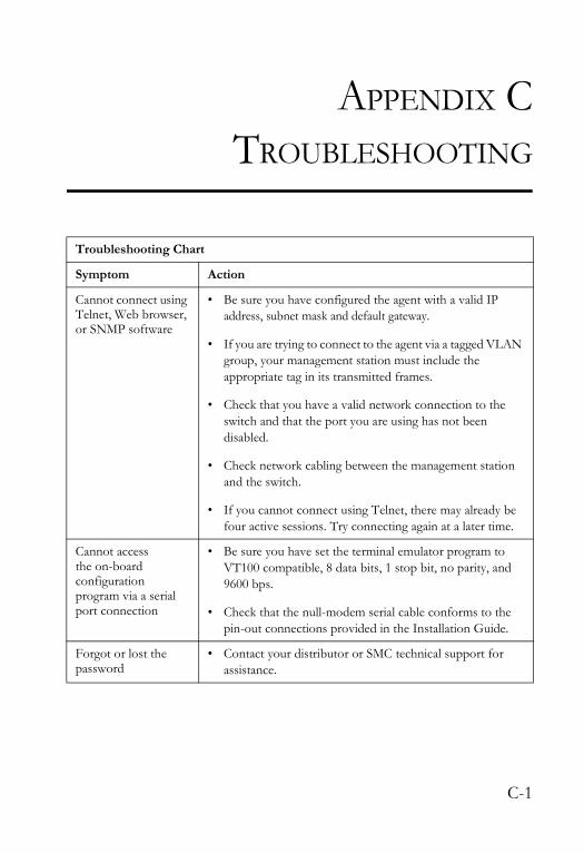
APPENDIX CTROUBLESHOOTING
Troubleshooting Chart
Symptom Action
Cannot connect using Telnet, Web browser, or SNMP software
• Be sure you have configured the agent with a valid IP address, subnet mask and default gateway.
• If you are trying to connect to the agent via a tagged VLAN group, your management station must include the appropriate tag in its transmitted frames.
• Check that you have a valid network connection to the switch and that the port you are using has not been disabled.
• Check network cabling between the management station and the switch.
• If you cannot connect using Telnet, there may already be four active sessions. Try connecting again at a later time.
Cannot access the on-board configuration program via a serial port connection
• Be sure you have set the terminal emulator program to VT100 compatible, 8 data bits, 1 stop bit, no parity, and 9600 bps.
• Check that the null-modem serial cable conforms to the pin-out connections provided in the Installation Guide.
Forgot or lost the password
• Contact your distributor or SMC technical support for assistance.
C-1

TROUBLESHOOTING
C-2
GLOSSARY
Auto-negotiationSignalling method allowing each node to select its optimum operational mode (e.g., 10 Mbps or 100 Mbps and half or full duplex) based on the capabilities of the node to which it is connected.
BOOTPBoot protocol used to load the operating system for devices connected to the network.
Dynamic Host Control Protocol (DHCP)Provides a framework for passing configuration information to hosts on a TCP/IP network. DHCP is based on the Bootstrap Protocol (BOOTP), adding the capability of automatic allocation of reusable network addresses and additional configuration options.
End StationA workstation, server, or other device that does not act as a network interconnection.
Full DuplexTransmission method that allows the switch and attached device to transmit and receive concurrently, effectively doubling the bandwidth of that link.
GARP VLAN Registration Protocol (GVRP)Defines a way for switches to exchange VLAN information in order to register necessary VLAN members on ports along the Spanning Tree so that VLANs defined in each switch can work automatically over a Spanning Tree network.
Generic Attribute Registration Protocol (GARP)GARP is a protocol that can be used by endstations and switches to register and propagate multicast group membership information in a switched environment so that multicast data frames are propagated only to those parts of a switched LAN containing registered endstations. Formerly called Group Address Registration Protocol.
Glossary-1
GLOSSARY
Group Attribute Registration Protocol See Generic Attribute Registration Protocol.
IEEE 802.1DSpecifies a general method for the operation of MAC bridges, including the Spanning Tree Protocol.
IEEE 802.1QVLAN Tagging—Defines Ethernet frame tags which carry VLAN information. It allows switches to assign endstations to different virtual LANs, and defines a standard way for VLANs to communicate across switched networks.
IEEE 802.1pAn IEEE standard for providing quality of service (QoS) in Ethernet networks. The standard uses packet tags that define up to eight traffic classes and allows switches to transmit packets based on the tagged priority value.
IEEE 802.3acDefines frame extensions for VLAN tagging.
IEEE 802.3xDefines Ethernet frame start/stop requests and timers used for flow control on full-duplex links.
IGMP SnoopingListening to IGMP Query and IGMP Report packets transferred between IP Multicast Routers and IP Multicast host groups to identify IP Multicast group members.
IGMP QueryOn each subnetwork, one IGMP-capable device should act as the querier — that is, the device that asks all hosts to report on the IP multicast groups they wish to join or to which they already belong. The elected querier will be the device with the lowest IP address in the subnetwork. Note that more than one device can be manually configured as a querier. However, this approach can generate an unnecessary amount of protocol traffic.
Glossary-2
GLOSSARY
Internet Group Management Protocol (IGMP)A protocol through which hosts can register with their local router for multicast services. If there is more than one multicast router on a given subnetwork, one of the routers is made the “querier” and assumes responsibility for keeping track of group membership.
In-Band ManagementManagement of the network from a station attached directly to the network.
IP Multicast FilteringA process whereby this switch can pass multicast traffic along to participating hosts.
Local Area Network (LAN) A group of interconnected computer and support devices.
Link AggregationSee Port Trunk.
Link Aggregation Control Protocol (LACP)Allows ports to automatically negotiate a trunked link with LACP-configured ports on another device.
Management Information Base (MIB)An acronym for Management Information Base. It is a set of database objects that contains information about a specific device.
Media Access Control (MAC)A portion of the networking protocol that governs access to the transmission medium, facilitating the exchange of data between network nodes.
Multicast SwitchingA process whereby the switch filters incoming multicast frames for services for which no attached host has registered, or forwards them to all ports contained within the designated multicast VLAN group.
Glossary-3
GLOSSARY
Out-of-Band ManagementManagement of the network from a station not attached to the network.
Port MirroringA method whereby data on a target port is mirrored to a monitor port for troubleshooting with a logic analyzer or RMON probe. This allows data on the target port to be studied unobtrusively.
Port TrunkDefines a network link aggregation and trunking method which specifies how to create a single high-speed logical link that combines several lower-speed physical links.
Remote Monitoring (RMON)RMON provides comprehensive network monitoring capabilities. It eliminates the polling required in standard SNMP, and can set alarms on a variety of traffic conditions, including specific error types.
Simple Network Management Protocol (SNMP)The application protocol in the Internet suite of protocols which offers network management services.
Spanning Tree Protocol (STP)A technology that checks your network for any loops. A loop can often occur in complicated or backup linked network systems. Spanning Tree detects and directs data along the shortest available path, maximizing the performance and efficiency of the network.
TelnetDefines a remote communication facility for interfacing to a terminal device over TCP/IP.
Transmission Control Protocol/Internet Protocol (TCP/IP)Protocol suite that includes TCP as the primary transport protocol, and IP as the network layer protocol.
Glossary-4

GLOSSARY
Trivial File Transfer Protocol (TFTP)A TCP/IP protocol commonly used for software downloads.
Virtual LAN (VLAN)A Virtual LAN is a collection of network nodes that share the same collision domain regardless of their physical location or connection point in the network. A VLAN serves as a logical workgroup with no physical barriers, and allows users to share information and resources as though located on the same LAN.
XModemA protocol used to transfer files between devices. Data is grouped in 128-byte blocks and error-corrected.
Glossary-5

GLOSSARY
Glossary-6
INDEX
Aaddress
aging 3-6, 4-31filtering 3-26, 4-28table 3-6, 3-24, 3-25, 4-26, 4-30, 4-31
aging time 3-6, 4-31
Bbroadcast storm control 3-7, 4-32
CClass of Service
configuring 3-8queue mapping 3-8
command line interface 5-1community string 3-40, 4-44
setting 2-7configuration settings, saving or
restoring 3-44connections, Web browser 2-1console
connecting 2-2, 2-4displaying port settings 3-9logout timer 4-53
Ddefault settings, system 1-4delay bound 3-8, 4-33downloading software 3-43, B-1
EEliteView management software 2-1
Ffeatures
management A-2switch A-1
firmwaredisplaying version 3-6, 4-9downloading 3-43, B-1upgrading 3-43, B-1
GGVRP 3-30, 4-46
Hhardware version, displaying 3-6, 4-9
IIEEE 802.1D 1-2IGMP
configuring 3-22static address 3-24
IP addresssetting 2-5, 4-13
Llog-in
console interface 4-1Web interface 3-2
Mmain menu
console interface 4-2Web interface 3-4
Index-1

INDEX
managementfeatures A-2options 2-1
menu map, console interface 4-3MIB support A-2mirror port, configuring 3-39, 4-18multicast filtering, configuring 3-21
Ppassword, setting 2-4, 3-42, 4-15port security 3-25, 4-30ports, configuring 3-10, 4-7priority queue 3-8, 4-24problems, troubleshooting C-1
Qquality of service 3-8, 4-24
Rrebooting the system 3-45, 4-52restarting the system 3-45, 4-52
SSNMP 2-1, 3-40, 4-42
community string 2-7, 3-40, 4-44enabling traps 3-41, 4-45trap manager 3-41, 4-45
software downloads 3-43, B-1software version, displaying 3-6, 4-9Spanning Tree Protocol 3-34, 4-35standards, IEEE A-2
static addresses 3-24, 4-26statistics, port 3-12, 4-8system software
downloading from server 3-43, B-1system, information 3-40, 4-9
Ttransmit delay bound 3-6, 4-33trap manager 3-41, 4-45troubleshooting C-1trunk
dynamic 3-16, 4-47static 3-14, 4-48
Uupgrading software 3-43, B-1user password 3-1, 3-42, 4-1
VVLANs, configuring 3-27, 4-20
WWeb browser connection 2-1Web interface
access requirements 3-1configuration buttons 3-3home page 3-2menu list 3-4panel display 3-3
Weighted Round Robin 3-8, 4-24
Index-2


38 TeslaIrvine, CA 92618Phone: (949) 679-8000
Model Number: SMC6709L2Publication Number: ?Revision Number: F3.08 E052003-R01
FOR TECHNICAL SUPPORT, CALL:From U.S.A. and Canada (24 hours a day, 7 days a week)
(800) SMC-4-YOU; (949) 679-8000; Fax: (949) 679-1481 From Europe (8:00 AM - 5:30 PM UK Time)
44 (0) 118 974 8700; Fax: 44 (0) 118 974 8701
INTERNETE-mail addresses:
[email protected]@smc-europe.com
Driver updates: http://www.smc.com/index.cfm?action=tech_support_drivers_downloads
World Wide Web: http://www.smc.com/http://www.smc-europe.com/
FOR LITERATURE OR ADVERTISING RESPONSE, CALL:
U.S.A. and Canada: (800) SMC-4-YOU; Fax (949) 679-1481Spain: 34-93-477-4935; Fax 34-93-477-3774UK: 44 (0) 118 974 8700; Fax 44 (0) 118 974 8701France: 33 (0) 41 38 32 32; Fax 33 (0) 41 38 01 58Italy: 39 02 739 12 33; Fax 39 02 739 14 17Benelux: 31 33 455 72 88; Fax 31 33 455 73 30Central Europe: 49 (0) 89 92861-0; Fax 49 (0) 89 92861-230Switzerland: 41 (0) 1 9409971; Fax 41 (0) 1 9409972Nordic: 46 (0) 868 70700; Fax 46 (0) 887 62 62Northern Europe: 44 (0) 118 974 8700; Fax 44 (0) 118 974 8701Eastern Europe: 34 -93-477-4920; Fax 34 93 477 3774Sub Saharan Africa: 27-11 314 1133; Fax 27-11 314 9133North Africa: 34 93 477 4920; Fax 34 93 477 3774Russia: 7 (095) 290 29 96; Fax 7 (095) 290 29 96PRC: 86-10-6235-4958; Fax 86-10-6235-4962Taiwan: 886-2-2659-9669; Fax 886-2-2659-9666Asia Pacific: (65) 238 6556; Fax (65) 238 6466Korea: 82-2-553-0860; Fax 82-2-553-7202Japan: 81-3-5645-5715; Fax 81-3-5645-5716Australia: 61-2-8875-7887; Fax 61-2-8875-7777India: 91-22-8204437; Fax 91-22-8204443
If you are looking for further contact information, please visit www.smc.com orwww.smc-europe.com.