Embed Size (px)
Citation preview
8/7/2019 Tìm hiểu thêm về xử lý tín hiệu Toolbox
http://slidepdf.com/reader/full/tim-hieu-them-ve-xu-ly-tin-hieu-toolbox 1/25
Tìm hiu thêm v x lý tín hiu Toolbox
FIR Filter Design Thit k b lc FIR
On this page« Trên trang này ...
FIR vs. IIR Filters B lc FIR so vi IIR
FIR Filter Summary Tóm tt lc FIR
Linear Phase Filters Giai on lc tuyn tính
Windowing Method Phng pháp ca s
Multiband FIR Filter Design with Transition Bands Thit k b lc FIR nhiu bng viBands chuyn
Constrained Least Squares FIR Filter Design Squares hn ch nht Thit k b lc FIR
Arbitrary-Response Filter Design Tùy tin, áp ng Filter Thit k
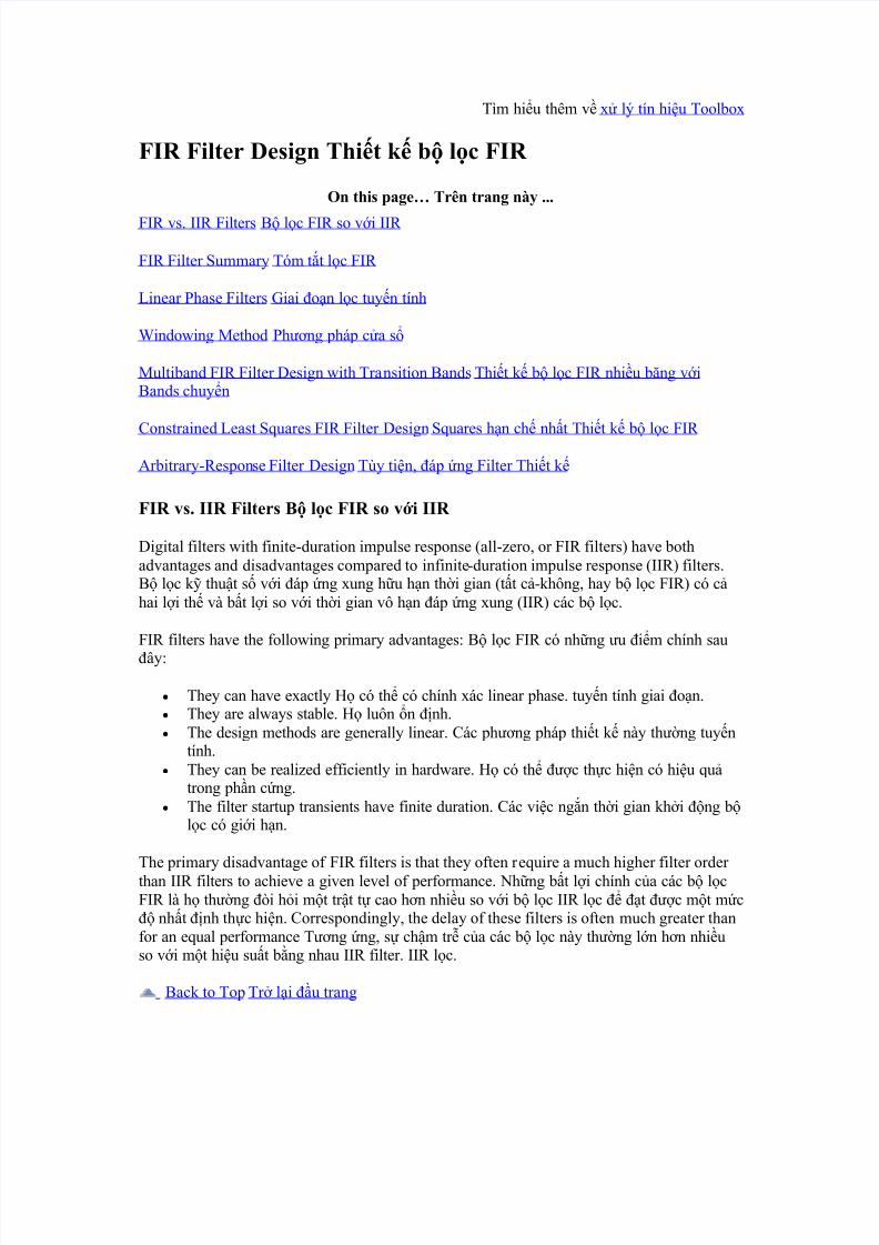
FIR vs. IIR Filters B lc FIR so vi IIR
Digital filters with finite-duration impulse response (all-zero, or FIR filters) have bothadvantages and disadvantages compared to infinite-duration impulse response (IIR) filters.B lc k thut s vi áp ng xung hu hn thi gian (tt c-không, hay b lc FIR) có chai li th và bt li so vi thi gian vô hn áp ng xung (IIR) các b lc.
FIR filters have the following primary advantages: B lc FIR có nhng u im chính sau
ây:
y They can have exactly H có th có chính xác linear phase. tuyn tính giai on.y They are always stable. H luôn n nh.y The design methods are generally linear. Các phng pháp thit k này thng tuyn
tính.y They can be realized efficiently in hardware. H có th c thc hin có hiu qu
trong phn cng.y The filter startup transients have finite duration. Các vic ngn thi gian khi ng b
lc có gii hn.
The primary disadvantage of FIR filters is that they often require a much higher filter order than IIR filters to achieve a given level of performance. Nhng bt li chính ca các b lcFIR là h thng òi hi mt trt t cao hn nhiu so vi b lc IIR lc t c mt mc nht nh thc hin. Correspondingly, the delay of these filters is often much greater thanfor an equal performance Tng ng, s chm tr ca các b lc này thng ln hn nhiuso vi mt hiu sut bng nhau IIR filter. IIR lc.
Back to Top Tr li u trang
8/7/2019 Tìm hiểu thêm về xử lý tín hiệu Toolbox
http://slidepdf.com/reader/full/tim-hieu-them-ve-xu-ly-tin-hieu-toolbox 2/25
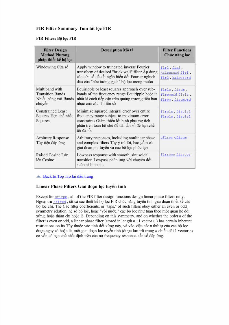
FIR Filter Summary Tóm tt lc FIR
FIR Filters B lc FIR
Filter Design
Method Phngpháp thit k b lc
Description Mô t Filter Functions
Chc nng lc
Windowing Ca s Apply window to truncated inverse Fourier transform of desired "brick wall" filter Áp dngcác ca s ct ngn bin i Fourier nghcho ca "bc tng gch" b lc mong mun
fir1 , fir2 ,kaiserord fir1 ,fir2 , kaiserord
Multiband withTransition Bands
Nhiu bng vi Bandschuyn
Equiripple or least squares approach over sub- bands of the frequency range Equiripple hoc ítnht là cách tip cn trên qung trng tiu bannhc ca các di tn s
firls , firpm ,firpmord firls ,firpm , firpmord
Constrained LeastSquares Hn ch nhtSquares
Minimize squared integral error over entirefrequency range subject to maximum error constraints Gim thiu li bình phng tích
phân trên toàn b ch di tn s hn chti a li
fircls , fircls1 fircls , fircls1
Arbitrary ResponseTùy tin áp ng
Arbitrary responses, including nonlinear phaseand complex filters Tùy ý tr li, bao gm cgiai on phi tuyn và các b lc phc tp
cfirpm cfirpm
Raised Cosine Lnlên Cosine
Lowpass response with smooth, sinusoidaltransition Lowpass phn ng vi chuyn isuôn s hình sin,
firrcos firrcos
Back to Top Tr li u trang
Linear Phase Filters Giai on lc tuyn tính
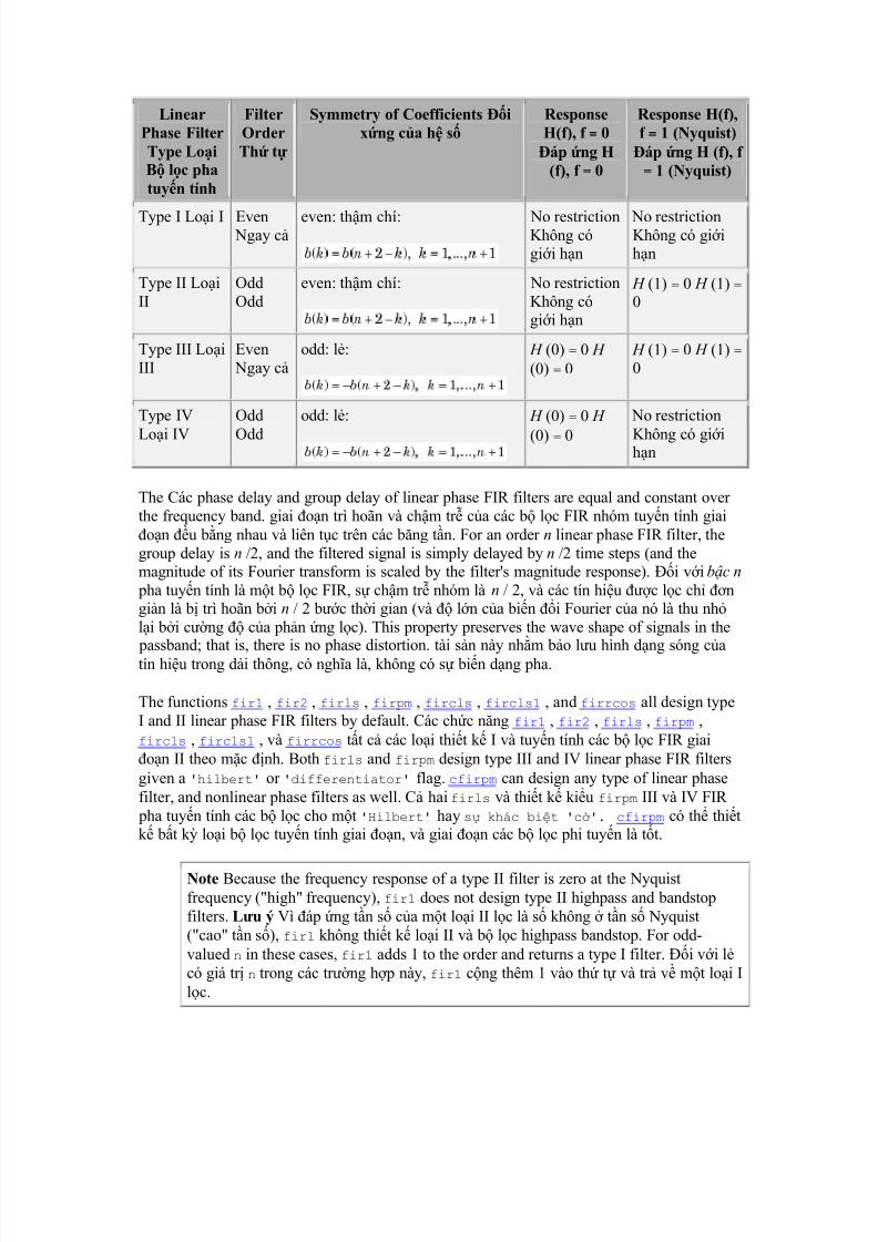
Except for cfirpm , all of the FIR filter design functions design linear phase filters only. Ngoi tr cfirpm , tt c các thit k b lc FIR chc nng tuyn tính giai on thit k các b lc ch. The Các filter coefficients, or "taps," of such filters obey either an even or oddsymmetry relation. h s b lc, hoc "vòi nc," các b lc nh tuân theo mt quan h ixng, hoc thm chí hoc l. Depending on this symmetry, and on whether the order n of thefilter is even or odd, a linear phase filter (stored in length n +1 vector b ) has certain inherent
restrictions on its Tùy thuc vào tính i xng này, và vào vic các n th t ca các b lcc ngay c hoc l, mt giai on lc tuyn tính (c lu tr trong n chiu dài 1 vector b) có vn có hn ch nht nh trên ca nó frequency response. tn s áp ng.
8/7/2019 Tìm hiểu thêm về xử lý tín hiệu Toolbox
http://slidepdf.com/reader/full/tim-hieu-them-ve-xu-ly-tin-hieu-toolbox 3/25
LinearPhase FilterType LoiB lc phatuyn tính
FilterOrderTh t
Symmetry of Coefficients ixng ca h s
ResponseH(f), f = 0
áp ng H(f), f = 0
Response H(f),f = 1 (Nyquist)
áp ng H (f), f = 1 (Nyquist)
Type I Loi I Even Ngay c even: thm chí: No restrictionKhông cógii hn
No restrictionKhông có giihn
Type II LoiII
OddOdd
even: thm chí: No restrictionKhông cógii hn
H (1) = 0 H (1) = 0
Type III LoiIII
Even Ngay c
odd: l: H (0) = 0 H (0) = 0
H (1) = 0 H (1) = 0
Type IV
Loi IV
Odd
Odd
odd: l: H (0) = 0 H
(0) = 0
No restriction
Không có giihn
The Các phase delay and group delay of linear phase FIR filters are equal and constant over the frequency band. giai on trì hoãn và chm tr ca các b lc FIR nhóm tuyn tính giaion u bng nhau và liên tc trên các bng tn. For an order n linear phase FIR filter, thegroup delay is n /2, and the filtered signal is simply delayed by n /2 time steps (and themagnitude of its Fourier transform is scaled by the filter's magnitude response). i vi bc n
pha tuyn tính là mt b lc FIR, s chm tr nhóm là n / 2, và các tín hiu c lc ch ngin là b trì hoãn bi n / 2 bc thi gian (và ln ca bin i Fourier ca nó là thu nhli bi cng ca phn ng lc). This property preserves the wave shape of signals in the
passband; that is, there is no phase distortion. tài sn này nhm bo lu hình dng sóng catín hiu trong di thông, có ngha là, không có s bin dng pha.
The functions fir1 , fir2 , firls , firpm , fircls , fircls1 , and firrcos all design typeI and II linear phase FIR filters by default. Các chc nng fir1 , fir2 , firls , firpm ,fircls , fircls1 , và firrcos tt c các loi thit k I và tuyn tính các b lc FIR giaion II theo mc nh. Both firls and firpm design type III and IV linear phase FIR filtersgiven a 'hilbert' or 'differentiator' flag. cfirpm can design any type of linear phasefilter, and nonlinear phase filters as well. C hai firls và thit k kiu firpm III và IV FIR
pha tuyn tính các b lc cho mt 'Hilbert' hay s khác bit 'c'. cfirpm có th thitk bt k loi b lc tuyn tính giai on, và giai on các b lc phi tuyn là tt.
Note Because the frequency response of a type II filter is zero at the Nyquistfrequency ("high" frequency), fir1 does not design type II highpass and bandstopfilters. Lu ý Vì áp ng tn s ca mt loi II lc là s không tn s Nyquist("cao" tn s), fir1 không thit k loi II và b lc highpass bandstop. For odd-valued n in these cases, fir1 adds 1 to the order and returns a type I filter. i vi lcó giá tr n trong các trng hp này, fir1 cng thêm 1 vào th t và tr v mt loi Ilc.
8/7/2019 Tìm hiểu thêm về xử lý tín hiệu Toolbox
http://slidepdf.com/reader/full/tim-hieu-them-ve-xu-ly-tin-hieu-toolbox 4/25
Back to Top Tr li u trang
Windowing Method Phng pháp ca s
Consider the Hãy xem xét ideal, or "brick wall," digital lý tng, hay "bc tng gch," kthut s lowpass filter with a cutoff frequency of 0 rad/s. lowpass filter vi mt tn s ct
ca 0 rad / s. This filter has magnitude 1 at all frequencies with magnitude less than 0 ,and magnitude 0 at frequencies with magnitude between 0 and . B lc này có ln 1 titt c các tn s có ln nh hn 0, và ln 0 các tn s vi ln gia 0 và . ItsCa nó impulse response sequence h ( n ) is chui phn ng xung h (n) là
This filter is not implementable since its impulse response is infinite and noncausal. B lcnày không implementable t áp ng xung ca nó là vô hn và noncausal. To create a finite-duration impulse response, truncate it by applying a to ra mt áp ng xung hu hn thi
gian, ct nó bng cách áp dng mt window. ca s. By retaining the central section of impulse response in this truncation, you obtain a linear phase FIR filter. Bng cách gi li phn trung tâm ca áp ng xung trong ct ngn này, bn có c mt b lc FIR pha tuyntính. For example, a length 51 filter with a lowpass cutoff frequency 0 of 0.4 rad/s is Víd, mt chiu dài 51 b lc vi mt tn s ct lowpass 0 trên 0,4 rad / s là
b = 0.4*sinc(0.4*(-25:25)); b = 0,4 * sinc ( 0,4 * (-25:25));
The window applied here is a simple Các ca s ng dng ây là mt n gin rectangular window. ca s hình ch nht. By Parseval's theorem, this is the length 51 filter that bestapproximates the ideal lowpass filter, in the integrated least squares sense. Bng nh lýParseval, iu này là chiu dài 51 b lc tt nht xp x vi lowpass b lc lý tng, trong ý
ngha tích hình vuông ít nht. The following command displays the filter's frequencyresponse in FVTool: Các lnh sau ây s hin th áp ng tn s ca b lc trong FVTool:
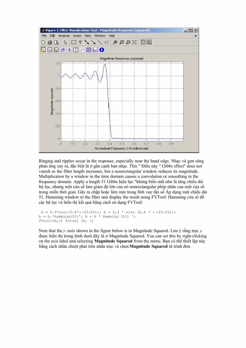
fvtool(b,1) fvtool (b, 1)
Note that the y -axis shown in the figure below is in Magnitude Squared. Lu ý rng trc y c hin th trong hình di ây là Magnitude Squared. You can set this by right-clickingon the axis label and selecting Magnitude Squared from the menu. Bn có th thit lp này
bng cách nhn chut phi trên nhãn trc và chn Magnitude Squared t trình n.
8/7/2019 Tìm hiểu thêm về xử lý tín hiệu Toolbox
http://slidepdf.com/reader/full/tim-hieu-them-ve-xu-ly-tin-hieu-toolbox 5/25
Ringing and ripples occur in the response, especially near the band edge. Nhc và gn sóng phn ng xy ra, c bit là gn cnh ban nhc. This " iu này " Gibbs effect" does notvanish as the filter length increases, but a nonrectangular window reduces its magnitude.Multiplication by a window in the time domain causes a convolution or smoothing in the
frequency domain. Apply a length 51 Gibbs hiu lc "không bin mt nh là tng chiu dài b lc, nhng mt ca s làm gim ln ca nó nonrectangular phép nhân ca mt ca strong min thi gian. Gây ra chp hoc làm mn trong lnh vc tn s Áp dng mt chiu dài51. Hamming window to the filter and display the result using FVTool: Hamming ca s các b lc và hin th kt qu bng cách s dng FVTool:
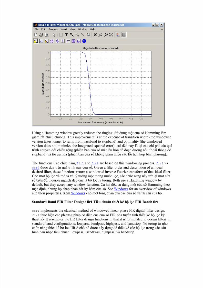
b = 0.4*sinc(0.4*(-25:25)); b = 0,4 * sinc (0,4 * ( -25:25)); b = b.*hamming(51)'; b = b * Hamming (51) '; fvtool(b,1) fvtool (b, 1)
Note that the y -axis shown in the figure below is in Magnitude Squared. Lu ý rng trc y c hin th trong hình di ây là Magnitude Squared. You can set this by right-clickingon the axis label and selecting Magnitude Squared from the menu. Bn có th thit lp này
bng cách nhn chut phi trên nhãn trc và chn Magnitude Squared t trình n.
8/7/2019 Tìm hiểu thêm về xử lý tín hiệu Toolbox
http://slidepdf.com/reader/full/tim-hieu-them-ve-xu-ly-tin-hieu-toolbox 6/25
Using a Hamming window greatly reduces the ringing. S dng mt ca s Hamming làmgim rt nhiu chuông. This improvement is at the expense of transition width (the windowedversion takes longer to ramp from passband to stopband) and optimality (the windowedversion does not minimize the integrated squared error). ci tin này là ti các chi phí ca quá
trình chuyn i chiu rng (phiên bn ca s mt lâu hn on ng ni t di thông stopband) và ti u hóa (phiên bn ca s không gim thiu các li tích hp bình phng).
The functions Các chc nng fir1 and fir2 are based on this windowing process. fir1 vàfir2 c da trên quá trình này ca s. Given a filter order and description of an idealdesired filter, these functions return a windowed inverse Fourier transform of that ideal filter.Cho mt b lc và mô t v lý tng mt mong mun lc, các chc nng này tr li mt cas bin i Fourier nghch o ca là b lc lý tng. Both use a Hamming window bydefault, but they accept any window function. C hai u s dng mt ca s Hamming theomc nh, nhng h chp nhn bt k hàm ca s. See Windows for an overview of windowsand their properties. Xem Windows cho mt tng quan ca các ca s và tài sn ca h.
Standard Band FIR Filter Design: fir1 Tiêu chun thit k b lc FIR Band: fir1
fir1 implements the classical method of windowed linear phase FIR digital filter design.fir1 thc hin các phng pháp c in ca ca s FIR pha tuyn tính thit k b lc kthut s. It resembles the IIR filter design functions in that it is formulated to design filters instandard band configurations: lowpass, bandpass, highpass, and bandstop. Nó tng t nhchc nng thit k b lc IIR ch nó c xây dng thit k các b lc trong các cuhình ban nhc tiêu chun: lowpass, BandPass, highpass, và bandstop.
8/7/2019 Tìm hiểu thêm về xử lý tín hiệu Toolbox
http://slidepdf.com/reader/full/tim-hieu-them-ve-xu-ly-tin-hieu-toolbox 7/25
The statements Các báo cáo
n = 50; n = 50; Wn = 0.4; WN = 0,4; b = fir1(n,Wn); b = fir1 (n, WN);
create row vector b
containing the coefficients of the order n
Hamming-windowed filter. tob vector hàng có cha các h s ca n-ca s Hamming lc. This is a ây là mt lowpass,linear phase FIR filter with cutoff frequency Wn . Wn is a number between 0 and 1, where 1corresponds to the Nyquist frequency, half the sampling frequency. lowpass, tuyn tính giaion lc FIR vi tn s ct WN. WN là mt con s gia 0 và 1, vi 1 tng ng vi các tn s
Nyquist, mt na tn s ly mu. (Unlike other methods, here Wn corresponds to the 6 dB point.) For a (Không ging nh các phng pháp khác, ây WN tng ng vi im dB 6.)i vi mt highpass filter, simply append the string 'high' to the function's parameter list.highpass lc, ch cn thêm chui 'cao' cho danh sách tham s ca hàm. For a bandpass or i vi mt BandPass hay bandstop filter, specify Wn as a two-element vector containing the
passband edge frequencies; append the string 'stop' for the bandstop configuration. bandstop lc, ch nh WN nh là mt phn t vector hai có cha cnh tn s di thông; thêm
stop 'chui' cho cu hình bandstop.
b = fir1(n,Wn,window) uses the b = fir1 (n, WN, ca s) s dng window specifiedin column vector window for the design. ca s quy nh ti ca s vector ct cho thit k.The vector window must be n+1 elements long. Ca s vector phi c n +1 phn t dài. If you do not specify a window, fir1 applies a Hamming window. Nu bn không ch nh mtca s, fir1 áp dng mt ca s Hamming.
K aiser Window Order Estimation. The kaiserord function estimates the filter order,cutoff frequency, and Kaiser window beta parameter needed to meet a given set of specifications. Theo c tính K aiser Window. Các kaiserord chc nng c tính các b
lc, tn s ct, và bn beta ca s Kaiser thông s cn thit áp ng mt tp các chi tit kthut. Given a vector of frequency band edges and a corresponding vector of magnitudes, aswell as maximum allowable ripple, kaiserord returns appropriate input parameters for thefir1 function. Cho mt vector ca các cnh tng ng vi bng tn s và vector mt ln,cng nh các gn sóng cho phép ti a, kaiserord tr v thông s u vào thích hp cho cácfir1 chc nng.
Multiband FIR Filter Design: fir2 Thit k b lc FIR nhiu bng: fir2
The fir2 function also designs windowed FIR filters, but with an arbitrarily shaped piecewise linear frequency response. Các fir2 chc nng cng thit k b lc FIR ca s,nhng vi mt piecewise tuyn tính tn s áp ng hình tùy tin. This is in contrast to fir1 ,
which only designs filters in standard lowpass, highpass, bandpass, and bandstopconfigurations. iu này trái ngc vi fir1 , mà ch thit k các b lc trong lowpass tiêuchun, highpass, BandPass, và cu hình bandstop.
The commands Các lnh
n = 50; n = 50; f = [0 .4 .5 1]; f = [0 0,4 0,5 1]; m = [1 1 0 0]; m = [1 1 0 0];
8/7/2019 Tìm hiểu thêm về xử lý tín hiệu Toolbox
http://slidepdf.com/reader/full/tim-hieu-them-ve-xu-ly-tin-hieu-toolbox 8/25
b = fir2(n,f,m); b = fir2 (n, e, m);
return row vector b containing the n+1 coefficients of the order n FIR filter whose frequency-magnitude characteristics match those given by vectors f and m . f is a vector of frequency
points ranging from 0 to 1, where 1 represents the Nyquist frequency. m is a vector containingthe desired magnitude response at the points specified in f . tr v vector b hàng có cha n
+1 h s ca b lc FIR n có ln phù hp vi nhng c tính tn s c a ra bivect f và m. f là mt vector các im tn s t 0 n 1, vi 1 là tn s Nyquist. m là mtvector cha các phn ng cng mong mun ti các im quy nh ti f. (The IIR counterpart of this function is yulewalk , which also designs filters based on arbitrary
piecewise linear magnitude responses. See IIR Filter Design for details.) (Các i tác IIR cachc nng này là yulewalk , mà cng thit k các b lc da trên các tuyn biên phn ng
piecewise tùy ý xem. IIR lc Thit k chi tit.)
Back to Top Tr li u trang
Multiband FIR Filter Design with Transition Bands Thit k b lc FIR nhiu
bng vi Bands chuynThe firls and firpm functions provide a more general means of specifying the ideal desiredfilter than the fir1 and fir2 functions. Các firls và firpm chc nng cung cp mt vtng có ngha là nhiu hn ch nh lý tng mong mun lc hn fir1 và fir2 chc nng.These functions design Hilbert transformers, differentiators, and other filters with oddsymmetric coefficients (type III and type IV linear phase). Nhng thit k chc nng Hilbert
bin, phân bit, và các b lc khác vi h s l i xng (loi III và loi IV giai on tuyntính). They also let you include transition or "don't care" regions in which the error is notminimized, and perform band dependent weighting of the minimization. H cng cho phép
bn bao gm chuyn i hoc "không quan tâm" khu vc mà li không phi là gim thiu, vàthc hin trng gim thiu ph thuc ca ban nhc này.
The firls function is an extension of the fir1 and fir2 functions in that it minimizes theChc nng firls là mt m rng ca các chc nng và fir2 fir1 ch nó gim thiuintegral of the square of the error between the desired frequency response and the actualfrequency response. tách ri ca các bình phng ca li gia mong mun áp ng tn s vàtn s áp ng thc t.
The firpm function implements the Parks-McClellan algorithm, which uses the Remezexchange algorithm and Chebyshev approximation theory to design filters with optimal fits
between the desired and actual frequency responses. Firpm chc nng thc hin các-McClellan thut toán Công viên, trong ó s dng các thut toán trao i và lý thuyt xp xRemez Chebyshev thit k các b lc vi phù hp vi ti u gia thc t và áp ng tns mong mun. The filters are optimal in the sense that they minimize the maximum Các blc c ti u theo ngha là h gim thiu ti a error between the desired frequencyresponse and the actual frequency response; they are sometimes called li gia mong munáp ng tn s và tn s áp ng thc t, h ôi khi c gi là minimax filters. minimax blc. Filters designed in this way exhibit an equiripple behavior in their frequency response,and hence are also known as B lc c thit k trong cuc trin lãm này là mt hành viequiripple cách áp ng tn s ca h, và vì th còn c gi là equiripple filters. equiripple
b lc. The Parks-McClellan FIR filter design algorithm is perhaps the most popular and
8/7/2019 Tìm hiểu thêm về xử lý tín hiệu Toolbox
http://slidepdf.com/reader/full/tim-hieu-them-ve-xu-ly-tin-hieu-toolbox 9/25
widely used FIR filter design methodology. Các khu-McClellan thut toán thit k b lc FIR có l là ph bin nht và s dng rng rãi phng pháp thit k b lc FIR.
The syntax for firls and firpm is the same; the only difference is their minimizationschemes. Cú pháp firls và firpm là nh nhau; s khác bit duy nht là gim thiu cácchng trình ca h. The next example shows how filters designed with firls and firpm
reflect these different schemes. Ví d tip theo cho thy các b lc c thit k vi firls và firpm phn ánh nhng án khác nhau.
Basic Configurations Cu hình c bn
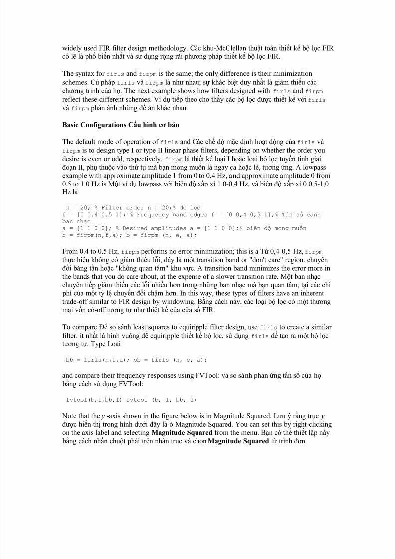
The default mode of operation of firls and Các ch mc nh hot ng ca firls vàfirpm is to design type I or type II linear phase filters, depending on whether the order youdesire is even or odd, respectively. firpm là thit k loi I hoc loi b lc tuyn tính giaion II, ph thuc vào th t mà bn mong mun là ngay c hoc l, tng ng. A lowpassexample with approximate amplitude 1 from 0 to 0.4 Hz, and approximate amplitude 0 from0.5 to 1.0 Hz is Mt ví d lowpass vi biên xp x 1 0-0,4 Hz, và biên xp x 0 0,5-1,0Hz là
n = 20; % Filter order n = 20;% lcf = [0 0.4 0.5 1]; % Frequency band edges f = [0 0,4 0,5 1];% Tn s cnhban nhca = [1 1 0 0]; % Desired amplitudes a = [1 1 0 0];% biên mong munb = firpm(n,f,a); b = firpm (n, e, a);
From 0.4 to 0.5 Hz, firpm performs no error minimization; this is a T 0,4-0,5 Hz, firpm thc hin không có gim thiu li, ây là mt transition band or "don't care" region. chuyni bng tn hoc "không quan tâm" khu vc. A transition band minimizes the error more inthe bands that you do care about, at the expense of a slower transition rate. Mt ban nhcchuyn tip gim thiu các li nhiu hn trong nhng ban nhc mà bn quan tâm, ti các chi
phí ca mt t l chuyn i chm hn. In this way, these types of filters have an inherenttrade-off similar to FIR design by windowing. Bng cách này, các loi b lc có mt thngmi vn có-off tng t nh thit k ca ca s FIR.
To compare so sánh least squares to equiripple filter design, use firls to create a similar filter. ít nht là hình vuông equiripple thit k b lc, s dng firls to ra mt b lctng t. Type Loi
bb = firls(n,f,a); bb = firls (n, e, a);
and compare their frequency responses using FVTool: và so sánh phn ng tn s ca h bng cách s dng FVTool:
fvtool(b,1,bb,1) fvtool (b, 1, bb, 1)
Note that the y -axis shown in the figure below is in Magnitude Squared. Lu ý rng trc y c hin th trong hình di ây là Magnitude Squared. You can set this by right-clickingon the axis label and selecting Magnitude Squared from the menu. Bn có th thit lp này
bng cách nhn chut phi trên nhãn trc và chn Magnitude Squared t trình n.
8/7/2019 Tìm hiểu thêm về xử lý tín hiệu Toolbox
http://slidepdf.com/reader/full/tim-hieu-them-ve-xu-ly-tin-hieu-toolbox 10/25
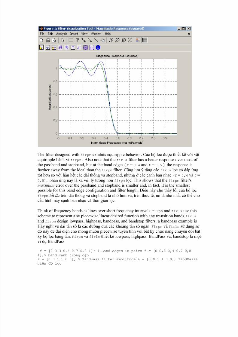
The filter designed with firpm exhibits equiripple behavior. Các b lc c thit k vi vtequiripple hành vi firpm. Also note that the firls filter has a better response over most of the passband and stopband, but at the band edges ( f = 0.4 and f = 0.5 ), the response isfurther away from the ideal than the firpm filter. Cng lu ý rng các firls lc có áp ng
tt hn so vi hu ht các di thông và stopband, nhng các cnh ban nhc (f = 0,4 và f =0,5), phn ng này là xa vi lý tng hn firpm lc. This shows that the firpm filter'smaximum error over the passband and stopband is smaller and, in fact, it is the smallest
possible for this band edge configuration and filter length. iu này cho thy li ca b lcfirpm t i a trên di thông và stopband là nh hn và, trên thc t, nó là nh nht có th chocu hình này cnh ban nhc và thi gian lc.
Think of frequency bands as lines over short frequency intervals. firpm and firls use thisscheme to represent any piecewise linear desired function with any transition bands.firls and firpm design lowpass, highpass, bandpass, and bandstop filters; a bandpass example isHãy ngh v di tn s là các ng qua các khong tn s ngn. Firpm và firls s dng s này i din cho mong mun piecewise tuyn tính vi bt k chc nng chuyn i bt
k b lc bng tn. Firpm và firls thit k lowpass, highpass, BandPass và, bandstop là mtví d BandPass
f = [0 0.3 0.4 0.7 0.8 1]; % Band edges in pairs f = [0 0,3 0,4 0,7 0,81];% Band cnh trong cpa = [0 0 1 1 0 0]; % Bandpass filter amplitude a = [0 0 1 1 0 0]; BandPass%biên lc
8/7/2019 Tìm hiểu thêm về xử lý tín hiệu Toolbox
http://slidepdf.com/reader/full/tim-hieu-them-ve-xu-ly-tin-hieu-toolbox 11/25
Technically, these f and a vectors define five bands: V k thut, các e và mt vect xác nhnm ban nhc:
y Two stopbands, from 0.0 to 0.3 and from 0.8 to 1.0 Hai stopbands, 0,0-0,3 và 0,8-1,0y A passband from 0.4 to 0.7 Mt di thông 0,4-0,7y Two transition bands, from 0.3 to 0.4 and from 0.7 to 0.8 Hai quá trình chuyn i các
ban nhc, 0,3-0,4 và 0,7-0,8
Example highpass and bandstop filters are Ví d và các b lc highpass bandstop c
f = [0 0.7 0.8 1]; % Band edges in pairs f = [0 0,7 0,8 1] ;% Band cnhtrong cpa = [0 0 1 1]; % Highpass filter amplitude a = [0 0 1 1]; Highpass% biên lcf = [0 0.3 0.4 0.5 0.8 1]; % Band edges in pairs f = [0 0,3 0,4 0,5 0,81];% Band cnh trong cpa = [1 1 0 0 1 1]; % Bandstop filter amplitude a = [1 1 0 0 1 1];% Bandstopbiên lc
An example multiband bandpass filter is Mt ví d BandPass nhiu bng b lc
f = [0 0.1 0.15 0.25 0.3 0.4 0.45 0.55 0.6 0.7 0.75 0.85 0.9 1]; f = [00,1 0,15 0,25 0,3 0,4 0,45 0,55 0,6 0,7 0,75 0,85 0,9 1]; a = [1 1 0 0 1 1 0 0 1 1 0 0 1 1]; a = [1 1 0 0 1 1 0 0 1 1 0 0 1 1];
Another possibility is a filter that has as a transition region the line connecting the passbandwith the stopband; this can help control "runaway" magnitude response in wide transitionregions: Mt kh nng khác là mt b lc mà ã là mt vùng chuyn tip các ng ngangni kt các di thông vi stopband các, iu này có th giúp kim soát phn ng cng "chy trn" trong khu vc chuyn tip rng:
f = [0 0.4 0.42 0.48 0.5 1]; f = [0 0,4 0,42 0,48 0,5 1]; a = [1 1 0.8 0.2 0 0]; % Passband, linear transition, a = [1 1 0,8 0,2 00];% di thông, tuyn tính chuyn tip,
% stopband % Stopband
The Weight Vector Các Vector Trng lng
Both firls and firpm allow C hai firls và firpm cho phép you to place more or lessemphasis on minimizing the error in certain frequency bands relative to others. bn t trngtâm nhiu hn hoc ít hn vào vic gim thiu các li trong các di tn s nht nh so vinhng ngi khác. To do this, specify a weight vector following the frequency and amplitudevectors. làm iu này, ch nh mt vector trng lng theo tn s và biên vect. Anexample lowpass equiripple filter with 10 times less ripple in the stopband than the passband
is An equiripple lowpass ví d b lc vi 10 ln ít gn trong stopband hn so vi di thông là
n = 20; % Filter order n = 20;% lcf = [0 0.4 0.5 1]; % Frequency band edges f = [0 0,4 0,5 1];% Tn s cnhban nhca = [1 1 0 0]; % Desired amplitudes a = [1 1 0 0];% biên mong munw = [1 10]; % Weight vector w = [1 10];% Trng lng vectorb = firpm(n,f,a,w); b = firpm (n, e, mt w,);
8/7/2019 Tìm hiểu thêm về xử lý tín hiệu Toolbox
http://slidepdf.com/reader/full/tim-hieu-them-ve-xu-ly-tin-hieu-toolbox 12/25
A legal weight vector is always half the length of the f and a vectors; there must be exactlyone weight per band. Mt vector trng pháp lut luôn luôn là mt na chiu dài ca e và mt vect, thì phi có chính xác mt trng lng mi ban nhc.
Anti-Symmetric Filters / Hilbert Transformers B lc chng i xng / HilbertTransformers
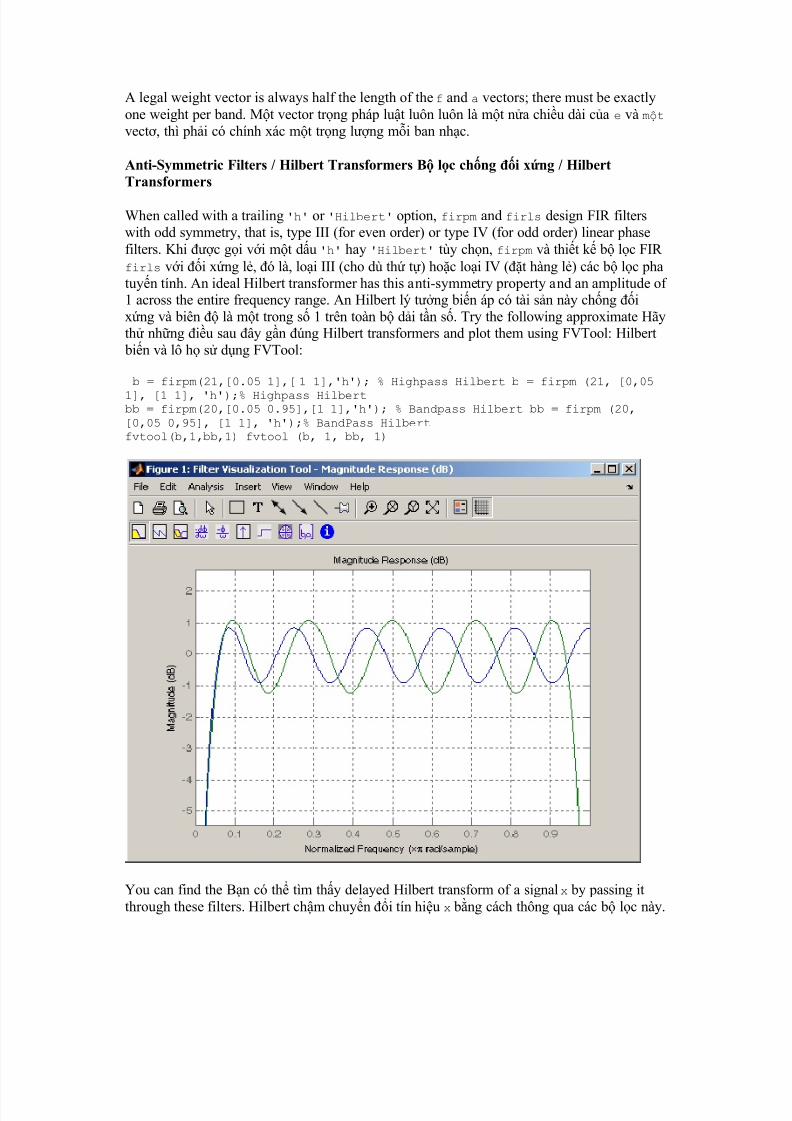
When called with a trailing 'h' or 'Hilbert' option, firpm and firls design FIR filterswith odd symmetry, that is, type III (for even order) or type IV (for odd order) linear phasefilters. Khi c gi vi mt du 'h' hay 'Hilbert' tùy chn, firpm và thit k b lc FIR firls vi i xng l, ó là, loi III (cho dù th t) hoc loi IV (t hàng l) các b lc phatuyn tính. An ideal Hilbert transformer has this anti-symmetry property and an amplitude of 1 across the entire frequency range. An Hilbert lý tng bin áp có tài sn này chng ixng và biên là mt trong s 1 trên toàn b di tn s. Try the following approximate Hãyth nhng iu sau ây gn úng Hilbert transformers and plot them using FVTool: Hilbert
bin và lô h s dng FVTool:
b = firpm(21,[0.05 1],[ 1 1],'h'); % Highpass Hilbert b = firpm (21, [0,05
1], [1 1], 'h');% Highpass Hilbertbb = firpm(20,[0.05 0.95],[1 1],'h'); % Bandpass Hilbert bb = firpm (20,[0,05 0,95], [1 1], 'h');% BandPass Hilbertfvtool(b,1,bb,1) fvtool (b, 1, bb, 1)
You can find the Bn có th tìm thy delayed Hilbert transform of a signal x by passing itthrough these filters. Hilbert chm chuyn i tín hiu x bng cách thông qua các b lc này.
8/7/2019 Tìm hiểu thêm về xử lý tín hiệu Toolbox
http://slidepdf.com/reader/full/tim-hieu-them-ve-xu-ly-tin-hieu-toolbox 13/25
fs = 1000; % Sampling frequency fs = 1000;% tn s ly mut = (0:1/fs:2)'; % Two second time vector t = (00:01 / fs: 2);% thi gianhai th hai vectorx = sin(2*pi*300*t); % 300 Hz sine wave example signal x = sin (2 * pi *300 * t);% 300 Hz Ví d tín hiu sóng sinxh = filter(bb,1,x); % Hilbert transform of x xh = lc (bb, 1, x);% Hil bertbin i ca x
The Các analytic signal corresponding to x is the complex signal that has x as its real part andthe Hilbert transform of x as its imaginary part. phân tích tín hiu tng ng vi x là tín hiu
phc tp có x là phn thc ca nó và bin i Hilbert ca x nh là mt phn tng tng camình. For this FIR method (an alternative to the i vi phng pháp này FIR (mt thay thcho hilbert function), you must delay x by half the filter order to create the analytic signal:Hilbert chc nng), bn phi trì hoãn x bi b lc trình t mt na to ra các tín hiu
phân tích:
xd = [zeros(10,1); x(1:length(x) -10)]; % Delay 10 samples xd = [s không(10,1); x (1: chiu dà i (x) -10)];% Delay 10 muxa = xd + j*xh; % Analytic signal xa = xd + k * xh;% phân tích tín hiu
This method does not work directly for filters of odd order, which require a Phng pháp nàykhông làm vic trc tip cho các b lc ca n hàng l, mà cn noninteger delay. s nguyênchm tr. In this case, the hilbert function, described in Specialized Transforms , estimatesthe analytic signal. Trong trng hp này, chc nng Hilbert, c mô t trong chuyênTransforms , c tính các tín hiu phân tích. Alternatively, use the resample function todelay the signal by a noninteger number of samples. Ngoài ra, s dng chc nng resample trì hoãn các tín hiu ca mt s s nguyên mu.
Differentiators Phân bit
Differentiation of a signal S khác bit ca tín hiu in the time domain is equivalent to
multiplication of the signal's Fourier transform by an imaginary ramp function. trong minthi gian là tng ng vi phép nhân ca Fourier ca tín hiu bin i ca mt hàm onng ni tng tng. That is, to differentiate a signal, pass it through a filter that has aresponse H () = j . ó là, phân bit mt tín hiu, vt qua nó thông qua mt b lc cómt phn ng H ) = k (. Approximate the ideal differentiator (with a delay) using Xp xkhác bit lý tng (vi mt s chm tr) bng cách s dng firpm or firls with a 'd' or 'differentiator' option: firpm hoc firls vi mt 'd' hoc 'khác bit' tùy chn:
b = firpm(21,[0 1],[0 pi],'d'); b = firpm (21 t ui, [0 1], [0 pi], 'd');
For a type III filter, the differentiation band should stop short of the Nyquist frequency, andthe amplitude vector must reflect that change to ensure the correct slope: i vi mt loi III
lc, ban nhc khác bit nên dng ngn ca các tn s Nyquist, và vector biên phi phnánh s thay i m bo dc úng:
bb = firpm(20,[0 0.9],[0 0.9*pi],'d'); bb = firpm (20, [0 0,9], [0 0,9 *pi], 'd');
In the 'd' mode, firpm weights the error by 1/ in nonzero amplitude bands to minimize themaximum relat ive error. firls weights the error by (1/) 2 in nonzero amplitude bands in the'd' mode. Trong ch 'd' là, trng lng firpm các li do 1 / trong các di biên khác
8/7/2019 Tìm hiểu thêm về xử lý tín hiệu Toolbox
http://slidepdf.com/reader/full/tim-hieu-them-ve-xu-ly-tin-hieu-toolbox 14/25
không gim thiu ti a li t ng i ch firls. T li bng cách (1 / ) 2 biên khác không trong ban nhc 'the' d trong.
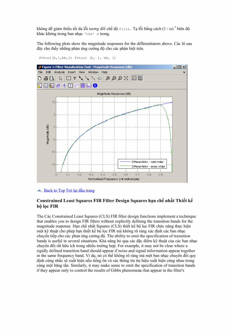
The following plots show the magnitude responses for the differentiators above. Các lô sauây cho thy nhng phn ng cng cho các phân bit trên.
fvtool(b,1,bb,1) fvtool (b, 1, bb, 1)
Back to Top Tr li u trang
Constrained Least Squares FIR Filter Design Squares hn ch nht Thit kb lc FIR
The Các Constrained Least Squares (CLS) FIR filter design functions implement a techniquethat enables you to design FIR filters without explicitly defining the transition bands for themagnitude response. Hn ch nht Squares (CLS) thit k b lc FIR chc nng thc hin
mt k thut cho phép bn thit k b lc FIR mà không rõ ràng xác nh các ban nhcchuyn tip cho các phn ng cng . The ability to omit the specification of transition bands is useful in several situations. Kh nng b qua các c im k thut ca các ban nhcchuyn i rt hu ích trong nhiu trng hp. For example, it may not be clear where arigidly defined transition band should appear if noise and signal information appear together in the same frequency band. Ví d, nó có th không rõ ràng mà mt ban nhc chuyn i quynh cng nhc s xut hin nu ting n và các thông tin tín hiu xut hin cùng nhau trongcùng mt bng tn. Similarly, it may make sense to omit the specification of transition bandsif they appear only to control the results of Gibbs phenomena that appear in the filter's
8/7/2019 Tìm hiểu thêm về xử lý tín hiệu Toolbox
http://slidepdf.com/reader/full/tim-hieu-them-ve-xu-ly-tin-hieu-toolbox 15/25
response. Tng t nh vy, nó có th làm cho tinh thn b qua các c im k thut cacác ban nhc chuyn i nu h xut hin ch kim soát các kt qu ca Gibbs hin tngxut hin trong phn ng ca b lc. See Selesnick, Lang, and Burrus [2] for discussion of this method. Xem Selesnick, Lang, và Burrus [2] tho lun các phng pháp này.
Instead of defining passbands, stopbands, and transition regions, the CLS method accepts a
cutoff frequency (for the highpass, lowpass, bandpass, or bandstop cases), or passband andstopband edges (for multiband cases), for the desired response. Thay vì passbands nh,stopbands, và vùng chuyn tip, các phng pháp CLS chp nhn mt tn s ct (i vihighpass, lowpass, BandPass, hoc trng hp bandstop), hoc di thông và stopband cnh(i vi trng hp nhiu bng), áp ng mong mun. In this way, the CLS methoddefines transition regions implicitly, rather than explicitly. Theo cách này, phng pháp xácnh vùng chuyn tip CLS ngm, ch không phi là rõ ràng.
The key feature of the CLS method is that it enables you to define upper and lower thresholdsthat contain the maximum allowable ripple in the magnitude response. Các tính nng chínhca phng pháp CLS là nó cho phép bn xác nh ngng trên và di có cha các gnsóng ti a cho phép trong áp ng cng . Given this constraint, the technique applies the
least square error minimization technique over the frequency range of the filter's response,instead of over specific bands. Do hn ch này, k thut này c áp dng các k thut gimthiu ít nht là hình vuông li trong di tn s áp ng ca b lc, thay vì trên các bng tnc th. The error minimization includes any areas of discontinuity in the ideal, "brick wall"response. Vic gim thiu li bao gm bt k lnh vc gián on trong lý tng, "bc tnggch" phn ng. An additional benefit is that the technique enables you to specify arbitrarilysmall peaks resulting from Gibbs' phenomena. Mt li ích na là k thut này cho phép bnch nh nh núi nh tùy tin thu c t hin tng Gibbs.
There are two toolbox functions that implement this design technique. Có hai chc nng hpcông c mà thc hin thit k k thut này.
Description Mô t FunctionChc nng
Constrained least square multiband FIR filter design Hn ch ít nht là hìnhvuông nhiu bng thit k b lc FIR
fircls fircls
Constrained least square filter design for lowpass and highpass linear phasefilters Hn ch ít nht là thit k b lc vuông lowpass và b lc giai onhighpass tuyn tính
fircls1 fircls1
For details on the calling syntax for these functions, see their reference descriptions in the
Function Reference. bit chi tit v các cú pháp cho các chc nng này, xem mô t tài liutham kho ca h trong chc nng tham kho.
Basic Lowpass and Highpass CLS Filter Design Lowpass c bn và Thit k HighpassFilter CLS
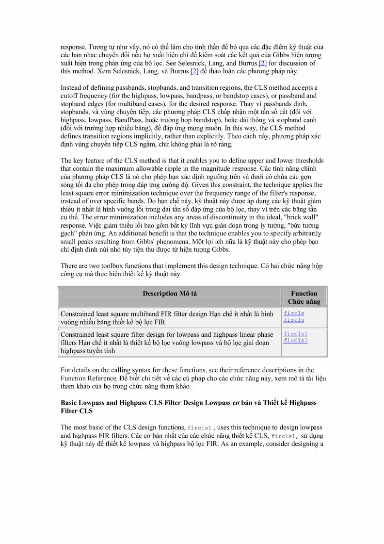
The most basic of the CLS design functions, fircls1 , uses this technique to design lowpassand highpass FIR filters. Các c bn nht ca các chc nng thit k CLS, fircls1, s dngk thut này thit k lowpass và highpass b lc FIR. As an example, consider designing a

8/7/2019 Tìm hiểu thêm về xử lý tín hiệu Toolbox
http://slidepdf.com/reader/full/tim-hieu-them-ve-xu-ly-tin-hieu-toolbox 16/25
filter with order 61 impulse response and cutoff frequency of 0.3 (normalized). Ví d, xemxét thit k mt b lc vi phn ng thúc y 61 và tn s ct ca 0,3 (bình thng).Further, define the upper and lower bounds that constrain the design process as: Hn na, xácnh các gii hn trên và di ó hn ch quá trình thit k nh:
y Maximum passband deviation from 1 (passband ripple) of 0.02. Di thông ti a
lch t 1 (di thông gn sóng) ca 0,02.y Maximum stopband deviation from 0 (stopband ripple) of 0.008. Stopband ti a
lch t 0 (stopband gn sóng) ca 0,008.
To approach this design problem using fircls1 , use the following commands: tip cnvn này thit k bng cách s dng fircls1, dùng các lnh sau ây:
n = 61; n = 61;
wo = 0.3; wo = 0,3; dp = 0.02; dp = 0,02; ds = 0.008; ds = 0,008; h = fircls1(n,wo,dp,ds); h = fircls1 (n, wo, dp, ds); fvtool(h,1) fvtool (h, 1)
Note that the y -axis shown below is in Magnitude Squared. Lu ý rng trc y c hin thdi ây là Magnitude Squared. You can set this by right-clicking on the axis label andselecting Magnitude Squared from the menu. Bn có th thit lp này bng cách nhn chut
phi trên nhãn trc và chn Magnitude Squared t trình n.
8/7/2019 Tìm hiểu thêm về xử lý tín hiệu Toolbox
http://slidepdf.com/reader/full/tim-hieu-them-ve-xu-ly-tin-hieu-toolbox 17/25
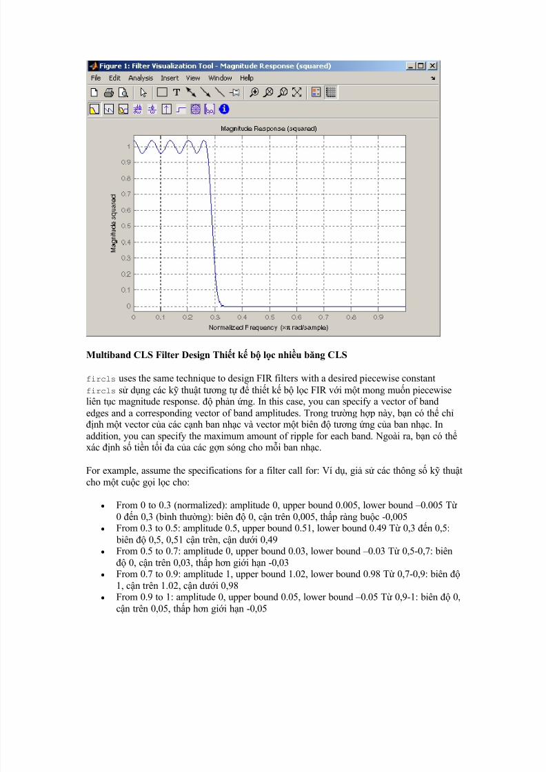
Multiband CLS Filter Design Thit k b lc nhiu bng CLS
fircls uses the same technique to design FIR filters with a desired piecewise constantfircls s dng các k thut tng t thit k b lc FIR vi mt mong mun piecewise
liên tc magnitude response. phn ng. In this case, you can specify a vector of bandedges and a corresponding vector of band amplitudes. Trong trng hp này, bn có th chnh mt vector ca các cnh ban nhc và vector mt biên tng ng ca ban nhc. Inaddition, you can specify the maximum amount of ripple for each band. Ngoài ra, bn có thxác nh s tin ti a ca các gn sóng cho mi ban nhc.
For example, assume the specifications for a filter call for: Ví d, gi s các thông s k thutcho mt cuc gi lc cho:
y From 0 to 0.3 (normalized): amplitude 0, upper bound 0.005, lower bound ±0.005 T0 n 0,3 (bình thng): biên 0, cn trên 0,005, thp ràng buc -0,005
y From 0.3 to 0.5: amplitude 0.5, upper bound 0.51, lower bound 0.49 T 0,3 n 0,5:
biên 0,5, 0,51 cn trên, cn di 0,49y From 0.5 to 0.7: amplitude 0, upper bound 0.03, lower bound ±0.03 T 0,5-0,7: biên
0, cn trên 0,03, thp hn gii hn -0,03y From 0.7 to 0.9: amplitude 1, upper bound 1.02, lower bound 0.98 T 0,7-0,9: biên
1, cn trên 1.02, cn di 0,98y From 0.9 to 1: amplitude 0, upper bound 0.05, lower bound ±0.05 T 0,9-1: biên 0,
cn trên 0,05, thp hn gii hn -0,05
8/7/2019 Tìm hiểu thêm về xử lý tín hiệu Toolbox
http://slidepdf.com/reader/full/tim-hieu-them-ve-xu-ly-tin-hieu-toolbox 18/25
Design a CLS filter with impulse response order 129 that meets these specifications: Thit kmt b lc vi CLS áp ng xung 129 áp ng các thông s k thut:
n = 129; n = 129; f = [0 0.3 0.5 0.7 0.9 1]; f = [0 0,3 0,5 0,7 0,9 1]; a = [0 0.5 0 1 0]; a = [0 0,5 0 1 0]; up = [0.005 0.51 0.03 1.02 0.05]; up = [0,005 0,51 0,03 1,02 0,05];
lo = [-0.005 0.49 -0.03 0.98 -0.05]; lo = [-0,005 0,49 -0,03 0,98 -0,05]; h = fircls(n,f,a,up,lo); h = fircls (n, e, mt, lên, l); fvtool(h,1) fvtool (h, 1)
Note that the y -axis shown below is in Magnitude Squared. Lu ý rng trc y c hin thdi ây là Magnitude Squared. You can set this by right-clicking on the axis label andselecting Magnitude Squared from the menu. Bn có th thit lp này bng cách nhn chut
phi trên nhãn trc và chn Magnitude Squared t trình n.
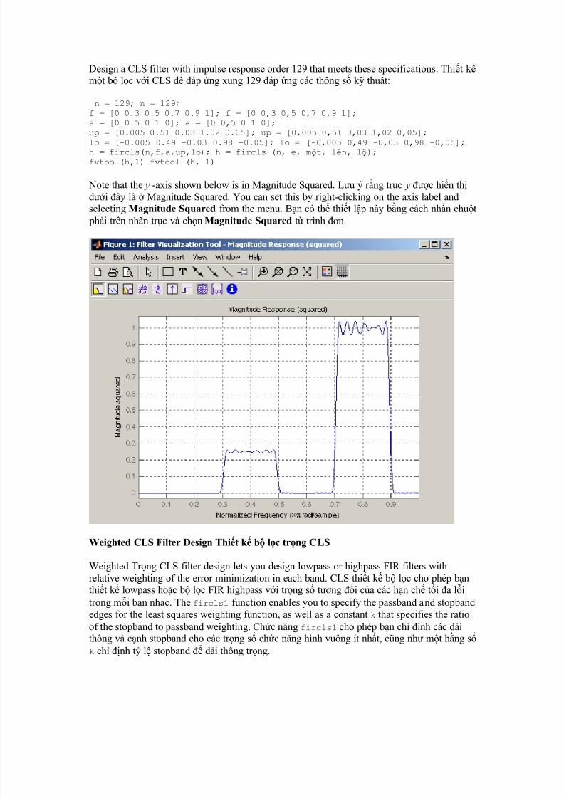
Weighted CLS Filter Design Thit k b lc trng CLS
Weighted Trng CLS filter design lets you design lowpass or highpass FIR filters withrelative weighting of the error minimization in each band. CLS thit k b lc cho phép bnthit k lowpass hoc b lc FIR highpass vi trng s tng i ca các hn ch ti a litrong mi ban nhc. The fircls1 function enables you to specify the passband and stopbandedges for the least squares weighting function, as well as a constant k that specifies the ratioof the stopband to passband weighting. Chc nng fircls1 cho phép bn ch nh các dithông và cnh stopband cho các trng s chc nng hình vuông ít nht, cng nh mt hng sk ch nh t l stopband di thông trng.
8/7/2019 Tìm hiểu thêm về xử lý tín hiệu Toolbox
http://slidepdf.com/reader/full/tim-hieu-them-ve-xu-ly-tin-hieu-toolbox 19/25
For example, consider specifications that call for an FIR filter with impulse response order of 55 and cutoff frequency of 0.3 (normalized). Ví d, hãy xem xét chi tit k thut ó gi chomt b lc FIR vi áp ng xung ca 55 và tn s ct ca 0,3 (bình thng). Also assumemaximum allowable passband ripple of 0.02 and maximum allowable stopband ripple of 0.004. Cng gi nh gn ti a cho phép ca các 0,02 di thông và gn stopband ti a cho
phép ca 0,004. In addition, add weighting requirements: Ngoài ra, thêm các yêu cu trng:
y Passband edge for the weight function of 0.28 (normalized) Cnh di thông cho cácchc nng trng lng 0,28 (bình thng)
y Stopband edge for the weight function of 0.32 Stopband cnh cho các chc nngtrng lng 0,32
y Weight error minimization 10 times as much in the stopband as in the passband Trnglng li gim thiu 10 ln so vi trong stopband nh trong di thông
To approach this using fircls1 , type tip cn này fircls1, loi s dng
n = 55; n = 55; wo = 0.3; wo = 0,3;
dp=
0.02; dp=
0,02; ds = 0.004; ds = 0,004; wp = 0.28; wp = 0,28; ws = 0.32; c = 0,32; k = 10; k = 10; h = fircls1(n,wo,dp,ds,wp,ws,k); h = fircls1 (n, wo, dp, ds, wp, c, k); fvtool(h,1) fvtool (h, 1)
Note that the y -axis shown below is in Magnitude Squared. Lu ý rng trc y c hin thdi ây là Magnitude Squared. You can set this by right-clicking on the axis label andselecting Magnitude Squared from the menu. Bn có th thit lp này bng cách nhn chut
phi trên nhãn trc và chn Magnitude Squared t trình n.
8/7/2019 Tìm hiểu thêm về xử lý tín hiệu Toolbox
http://slidepdf.com/reader/full/tim-hieu-them-ve-xu-ly-tin-hieu-toolbox 20/25
Back to Top Tr li u trang
Arbitrary-Response Filter Design Tùy tin, áp ng Filter Thit k
The cfirpm filter design function provides a tool for designing FIR filters with arbitrarycomplex responses. Các cfirpm chc nng thit k b lc cung cp mt công c thit k b lc FIR vi phn ng phc tp tùy ý. It differs from the other filter design functions inhow the frequency response of the filter is specified: it accepts the name of a function whichreturns the filter response calculated over a grid of frequencies. Nó khác vi các chc nngthit k b lc khác trong cách phn ng tn s ca b lc c xác nh: nó chp nhn tênca mt hàm tr v các phn ng lc c tính toán trên mt mng li các tn s. Thiscapability makes cfirpm a highly versatile and powerful technique for filter design. Khnng này làm cho cfirpm mt linh hot và mnh m k thut cao cho thit k b lc.
This design technique may be used to produce nonlinear-phase FIR filters, asymmetricfrequency-response filters (with complex coefficients), or more symmetric filters with custom
frequency responses. Thit k k thut này có th c s dng sn xut các b lc FIR pha phi tuyn, tn s áp ng b lc không i xng (vi h s phc tp), hoc nhiu b lci xng vi tn s phn ng tùy chnh.
The design algorithm optimizes the Chebyshev (or minimax) error using an extended Remez-exchange algorithm for an initial estimate. Các thut toán thit k ti u hóa Chebyshev(hoc minimax) li bng cách s dng mt thut toán Remez trao i m rng cho mt ctính ban u. If this exchange method fails to obtain the optimal filter, the algorithm switchesto an ascent-descent algorithm that takes over to finish the convergence to the optimal
8/7/2019 Tìm hiểu thêm về xử lý tín hiệu Toolbox
http://slidepdf.com/reader/full/tim-hieu-them-ve-xu-ly-tin-hieu-toolbox 21/25
solution. Nu phng pháp này không trao i có c nhng b lc ti u, thut toánchuyn sang mt thut toán leo-gc mà phi mt hn kt thúc s hi t các gii phápti u.
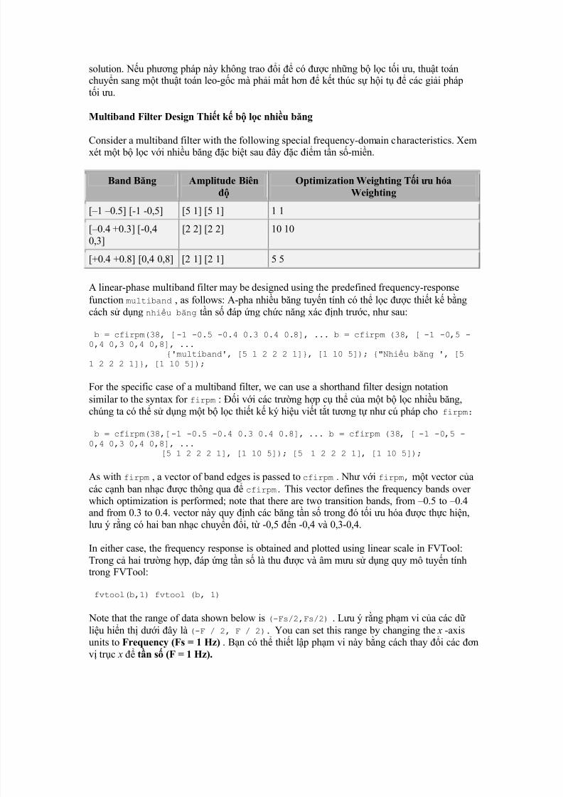
Multiband Filter Design Thit k b lc nhiu bng
Consider a multiband filter with the following special frequency-domain characteristics. Xemxét mt b lc vi nhiu bng c bit sau ây c im tn s-min.
Band Bng Amplitude Biên
OptimizationWeighting Ti u hóaWeighting
[±1 ±0.5] [-1 -0,5] [5 1] [5 1] 1 1
[±0.4 +0.3] [-0,40,3]
[2 2] [2 2] 10 10
[+0.4 +0.8] [0,4 0,8] [2 1] [2 1] 5 5
A linear-phase multiband filter may be designed using the predefined frequency-responsefunction multiband , as follows: A-pha nhiu bng tuyn tính có th lc c thit k bngcách s dng nhiu bng tn s áp ng chc nng xác nh trc, nh sau:
b = cfirpm(38, [-1 -0.5 -0.4 0.3 0.4 0.8], ... b = cfirpm (38, [ -1 -0,5 -0,4 0,3 0,4 0,8], ...
{'multiband', [5 1 2 2 2 1]}, [1 10 5]); {"Nhiu bng ', [51 2 2 2 1]}, [1 10 5]);
For the specific case of a multiband filter, we can use a shorthand filter design notationsimilar to the syntax for firpm : i vi các trng hp c th ca mt b lc nhiu bng,chúng ta có th s dng mt b lc thit k ký hiu vit tt tng t nh cú pháp cho firpm:
b = cfirpm(38,[-1 -0.5 -0.4 0.3 0.4 0.8], ... b = cfirpm (38, [ -1 -0,5 -0,4 0,3 0,4 0,8], ...
[5 1 2 2 2 1], [1 10 5]); [5 1 2 2 2 1], [1 10 5]);
As with firpm , a vector of band edges is passed to cfirpm . Nh vi firpm, mt vector cacác cnh ban nhc c thông qua cfirpm. This vector defines the frequency bands over which optimization is performed; note that there are two transition bands, from ±0.5 to ±0.4and from 0.3 to 0.4. vector này quy nh các bng tn s trong ó ti u hóa c thc hin,lu ý rng có hai ban nhc chuyn i, t -0,5 n -0,4 và 0,3-0,4.
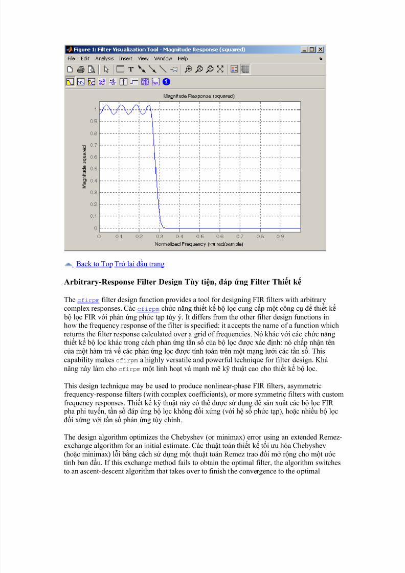
In either case, the frequency response is obtained and plotted using linear scale in FVTool:
Trong c hai trng hp, áp ng tn s là thu c và âm mu s dng quy mô tuyn tínhtrong FVTool:
fvtool(b,1) fvtool (b, 1)
Note that the range of data shown below is (-Fs/2,Fs/2) . Lu ý rng phm vi ca các dliu hin th di ây là (-F / 2, F / 2). You can set this range by changing the x -axisunits to Frequency (Fs = 1 Hz) . Bn có th thit lp phm vi này bng cách thay i các nv trc x tn s (F = 1 Hz).
8/7/2019 Tìm hiểu thêm về xử lý tín hiệu Toolbox
http://slidepdf.com/reader/full/tim-hieu-them-ve-xu-ly-tin-hieu-toolbox 22/25
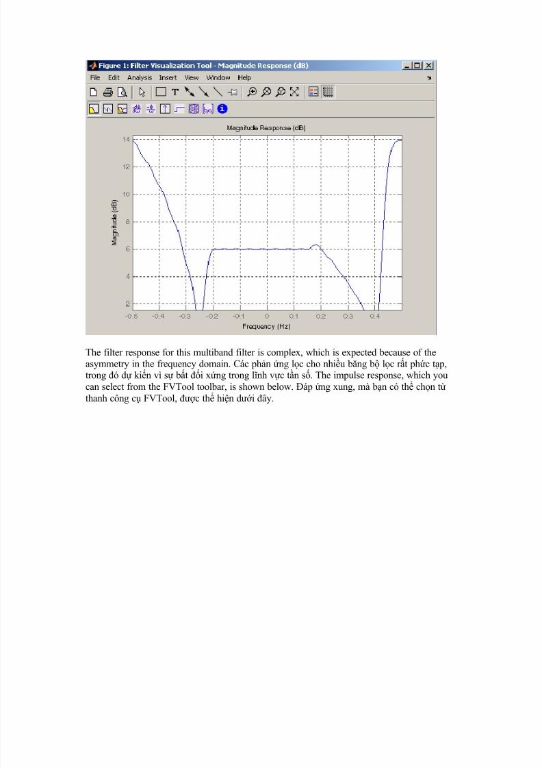
The filter response for this multiband filter is complex, which is expected because of theasymmetry in the frequency domain. Các phn ng lc cho nhiu bng b lc rt phc tp,trong ó d kin vì s bt i xng trong lnh vc tn s. The impulse response, which youcan select from the FVTool toolbar, is shown below. áp ng xung, mà bn có th chn tthanh công c FVTool, c th hin di ây.
8/7/2019 Tìm hiểu thêm về xử lý tín hiệu Toolbox
http://slidepdf.com/reader/full/tim-hieu-them-ve-xu-ly-tin-hieu-toolbox 23/25
Filter Design with Reduced Delay Thit k b lc vi Gim Delay
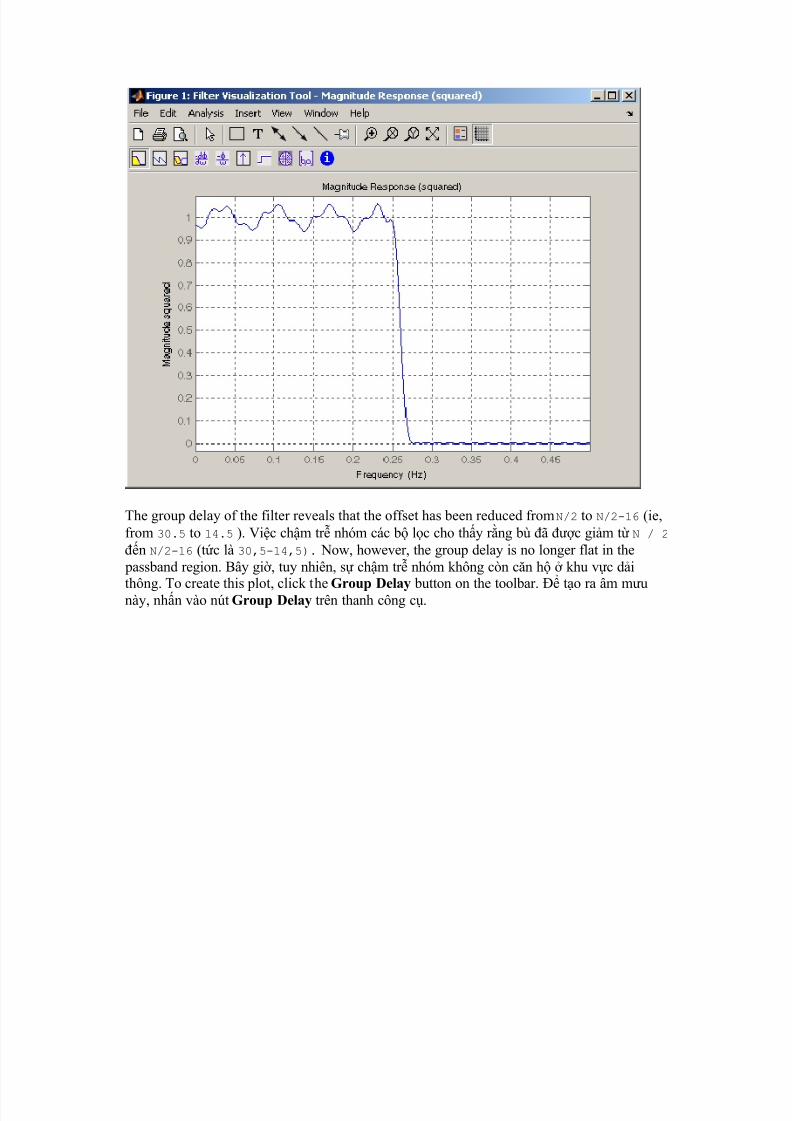
Consider the design of a 62-tap lowpass filter with a half-Nyquist cutoff. Xem xét các thit kca mt lowpass 62-tap lc vi mt ct na Nyquist. If we specify a negative offset value to
the lowpass filter design function, the group delay offset for the design is significantly lessthan that obtained for a standard linear-phase design. Nu chúng ta xác nh mt giá tr offsetâm lc lowpass thit k chc nng, s chm tr nhóm bù p cho vic thit k là ít hnáng k so vi thu c cho mt thit k pha tuyn tính tiêu chun. This filter design may becomputed as follows: Thit k b lc có th c tính nh sau:
b = cfirpm(61,[0 0.5 0.55 1],{'lowpass', -16}); b = cfirpm (61, [0 0,5 0,551], {'lowpass', -16});
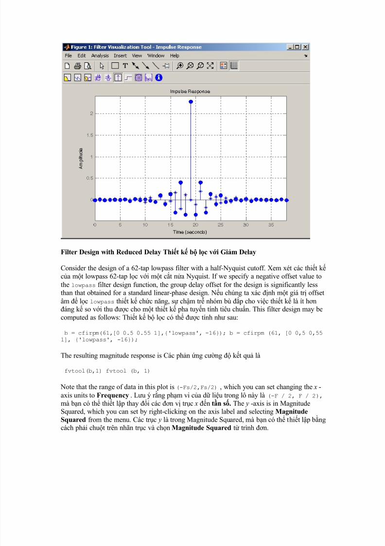
The resulting magnitude response is Các phn ng cng kt qu là
fvtool(b,1) fvtool (b, 1)
Note that the range of data in this plot is (-Fs/2,Fs/2) , which you can set changing the x -axis units to Frequency . Lu ý rng phm vi ca d liu trong lô này là (-F / 2, F / 2), mà bn có th thit lp thay i các n v trc x n tn s. The y -axis is in MagnitudeSquared, which you can set by right-clicking on the axis label and selecting MagnitudeSquared from the menu. Các trc y là trong Magnitude Squared, mà bn có th thit lp bngcách phi chut trên nhãn trc và chn Magnitude Squared t trình n.
8/7/2019 Tìm hiểu thêm về xử lý tín hiệu Toolbox
http://slidepdf.com/reader/full/tim-hieu-them-ve-xu-ly-tin-hieu-toolbox 24/25
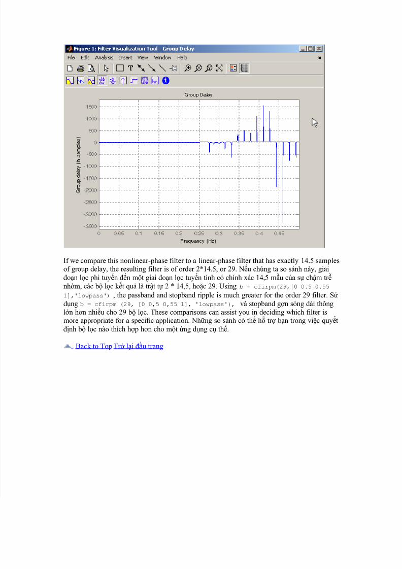
The group delay of the filter reveals that the offset has been reduced from N/2 to N/2-16 (ie,from 30.5 to 14.5 ). Vic chm tr nhóm các b lc cho thy rng bù ã c gim t N / 2 n N/2-16 (tc là 30,5-14,5). Now, however, the group delay is no longer flat in the
passband region. Bây gi, tuy nhiên, s chm tr nhóm không còn cn h khu vc di
thông. To create this plot, click the Group Delay button on the toolbar. to ra âm munày, nhn vào nút Group Delay trên thanh công c.
8/7/2019 Tìm hiểu thêm về xử lý tín hiệu Toolbox
http://slidepdf.com/reader/full/tim-hieu-them-ve-xu-ly-tin-hieu-toolbox 25/25
If we compare this nonlinear-phase filter to a linear-phase filter that has exactly 14.5 samplesof group delay, the resulting filter is of order 2*14.5, or 29. Nu chúng ta so sánh này, giaion lc phi tuyn n mt giai on lc tuyn tính có chính xác 14,5 mu ca s chm trnhóm, các b lc kt qu là trt t 2 * 14,5, hoc 29. Using b = cfirpm(29,[0 0.5 0.55
1],'lowpass') , the passband and stopband ripple is much greater for the order 29 filter. Sdng b = cfirpm (29, [0 0,5 0,55 1], 'lowpass'), và stopband gn sóng di thôngln hn nhiu cho 29 b lc. These comparisons can assist you in deciding which filter ismore appropriate for a specific application. Nhng so sánh có th h tr bn trong vic quytnh b lc nào thích hp hn cho mt ng dng c th.
Back to Top Tr li u trang