Embed Size (px)
Citation preview

TK206OBD
GPS+GPRS+OBD
1. Technical parameter
1).GSM:850/900/1800/1900 Quad band
2).GPRS: Class12, TCP/IP
3).Working Voltage:9-50V DC
4).Working current:≈22mA (12vDC)
5).Working current:≈12mA (24vDC)
6).GPS locating time:Cold start≈38s(Open sky)
Warm start≈32s
Hot start≈2s(Open sky)
7).GPS Precision:10m(2D RM)
8).Working temperature:-20℃~+70℃
9).Working humidity:20%~80%RH
10).Measurement:71(L)×49(W)×24(H)mm
11) GPS chips: U-bolx GSM chips: MT6261
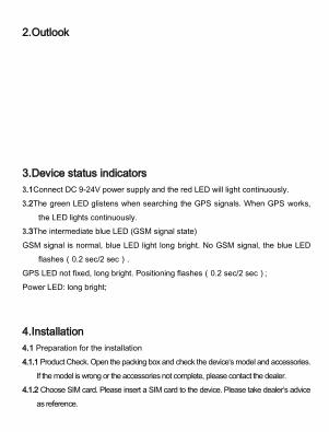
2.Outlook
3.Device status indicators
3.1Connect DC 9-24V power supply and the red LED will light continuously.
3.2The green LED glistens when searching the GPS signals. When GPS works,
the LED lights continuously.
3.3The intermediate blue LED (GSM signal state)
GSM signal is normal, blue LED light long bright. No GSM signal, the blue LED
flashes(0.2 sec/2 sec).
GPS LED not fixed, long bright. Positioning flashes(0.2 sec/2 sec);
Power LED: long bright;
4.Installation
4.1 Preparation for the installation
4.1.1 Product Check. Open the packing box and check the device‘s model and accessories.
If the model is wrong or the accessories not complete, please contact the dealer.
4.1.2 Choose SIM card. Please insert a SIM card to the device. Please take dealer’s advice
as reference.

4.1.3 SIM card installation. Discharge the cover of the device and uncover the SIM card
holder. Then insert the SIM card and cover SIM card holder (as follows).
4.1.4 Put back the front cover and screw it up.
4.1.5 Connect the device to the 9-50Vpower supply.(the red LED constant glow)
4.1.6 Install the device in the hidden place of the car;
The SIM card must be with GPRS function and enough deposit. If your SIM card need
input PIN when power on, please cancel it.
5.User Settings
5.1 Set class instruction
1) CENTER
Text command
Parameter Sample
CENTER Add
710#number# 711#number#
710#13500135000# 711#13800138000#
CENTER Del
D01# D02#
D01# D02#

Command Description
1)Center number can control the oil and power and resume factory settings
2) Center number can receive the call and text of vibration alarm and over speeding alarm. 3) SIM must display the income call number to control oil and
power. 4) Only one number can be center number. 5) Change center number must resend the command. 6)Add new center number by CETNER,A, and delete by CENTER,D
Command Feedback
Successful Setting:Add admin account 1 OK!
2) View administrator number
Text command
Parameter Sample
View 901# 901#
Command Description
This directive is used to view Device Manager number.
Command Feedback
Successful Setting:Admin1:
Admin2:
3) Authorized number set
Text command
Parameter Sample
Authorized Add
101# number # 102# number # 103# number #
1:101#13800138000#
2:102#12345678912#
3:103#12345678912#
Authorized Del
D11# D12# D13#
D11# D12# D13#
Command Description
1) Authorization number for SMS control oil.
2) only three numbers to set the authorization number
3) change the authorization number needs to delete the
previous number
Command Feedback
Successful Setting:Add Authorization account 1 OK!
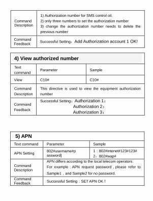
4) View authorized number
Text
command Parameter Sample
View C10# C10#
Command
Description
This directive is used to view the equipment authorization
number
Command
Feedback
Successful Setting:Authorization 1:
Authorization 2:
Authorization 3:
5) APN
Text command Parameter Sample
APN Setting 802#username#password]
1:802#intenet#123#123#
2:802#wap#
Command Description
APN differs according to the local telecom operators.
For example:APN request password,please refer to
Sample1,and Sample2 for no password.
Command Feedback
Successful Setting:SET APN OK!

6) Set / view SERVER
Text command Parameter Sample
SERVER Parameter
803#SERVER # port# 803#58.61.154.233#7018#
view SERVER
CIP# CIP#
Command Description
Change the IP and port when move to a new server
port:10~65535
1 is domain and 0 is IP;
Command Feedback
Successful Setting:set IP OK!
7) TIMER
Text command Parameter Sample
TIMEER Parameter setting
730#uploading interval# 730#20#
Command Description
Time scope:0,10~60 seconds; 0,no data uploading;
10~60,means time interval ; the default value is 15
seconds!
Command Feedback
Successful Setting:SET TIMER OK!
8) STATIC
Text command
Parameter Sample
STATIC SUP# time interval# SUP#5#
Command Description
Time scope : 1~60 minutes ; The device
has3Dtransmission and the default time interval are 5

minutes.
Command Feedback
Successful Setting:SET STATIC TIME OK!
9) Cancel the continuous upload
Text
command Parameter Sample
NUP NUP# NUP#
Command
Description
This command is used to cancel sending data to the
platform
If need again to restore the upload , you need to send
TIMEER Parameter setting or STATIC
Command
Feedback Successful Setting:Close upload gps information ok!
10) GMT
Text command
Parameter Sample
GMT 801#location, time#
801#E8#
Command Description
The default time zone is Beijing time. If time zone need revised, please operate according to the above command.
Command Feedback
Successful Setting:Set time zone ok!
11) VIBRATION

Text command Parameter Sample
VIBRATION Parameter
123#2#alarming way# 1) 123#2#3#
Set into vibration alarm time
V123#2# 1) V123#2# 2) V123#1#
Cancel vibration alarm
456# 456#
Command Description
the sensitivity value of the vibration is from 1 to 5,1is the
most sensitive and o is close. Alarming ways: 1, calling 2, texting, 3 calling and texting. Must set the center number and receiving number.
Command Feedback
set vibration alarm level,OK!
12) SPEEDING
Text
command Parameter Sample
SPEEDING
Parameter SSA#120#alarming way#
1)SPEEDING,120,3#
2)SPEEDING,120#
Command
Description
The speed scope is form 60-220, if the speed is no this
cope, the alarm is off.
Alarming :1, calling 2, texting, 3 calling and texting.
Must set the center number and receiving number.
Command
Feedback Successful Setting:set speeding alarm,OK!

13) RESET
Text
command Parameter Sample
RESET 930# 930#
Command
Description Reset the device
Command
Feedback Successful Setting:Reset system, ok!
14) FACTORY
Text
command Parameter Sample
Parameter 940# 940#
Command
Description
Restore the factory setting
Only center number can initial this function
Factory setting will recover to the original setting
Command
Feedback Successful Setting:FACTORY OK!
15) LANG

Text command
Parameter Sample
LANG Parameter
LANG1# LANG0#
LANG1# CHINESE,
LANG0# ENGLISH
Command Description
LANG1# :Command reply Chinese text LANG0# :Command reply English text
Command Feedback
Successful Setting:SET LANG OK!
16) WHERE
Text command
Parameter Sample
WHERE 988# 988#
Command Description
Check the longitude and altitude and other information of the device
Command Feedback
Reply with longitude and altitude, speed and IMEL.
17) URL
Text command
Parameter Sample
WHERE 666# 666#
Command Description
Check the location link of Google map
Command Feedback
<Datetime:12-07-05 13:21:30> http://maps.google.com/maps?q=N22.540885,E113.95265
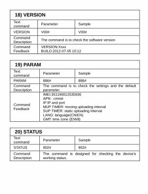
18) VERSION
Text command
Parameter Sample
VERSION V00# V00#
Command Description
The command is to check the software version
Command Feedback
VERSION:Xxxx BUILD:2012-07-05 10:12
19) PARAM
Text command
Parameter Sample
PARAM 886# 886#
Command Description
The command is to check the settings and the default parameter.
Command Feedback
IMEI:351190012535936 APN : cmnet IP:IP and port MUP TIMER: moving uploading interval SUP TIMER: static uploading interval LANG: language(CN/EN) GMT: time zone (E/W8)
20) STATUS Text command
Parameter Sample
STATUS 902# 902#
Command Description
The command is designed for checking the device’s working status.

Command Feedback
External power:ON/OFF GSM Signal:HIGH/MIDDLE/LOW GPS:FIXED/UNFIXED Vibrate Warning:ON/OFF
Pause:ON/OFF
6.OBD with diagnosis
1 Product Overview
This product is a professional-grade automotive OBD product has the following
characteristics:
1) Compact
2) the interface is simple (external interface simple and practical)
3) Easy to use (can be integrated via the serial port with a variety of automotive
electronic products)
4) Applicable models widely (equipped with OBD systems applicable to all
passenger cars)
This product has passed the standard diagnostic connector J1962 diagnostic
socket connection with the car, you can get all kinds of standard automotive OBD
data
And communicate via a standard serial port and other peripherals, as traditional
products to add new applications to bring customers more and better
Features and experiences.
This product is designed, excellent workmanship, stable and reliable performance,
online upgrades, new features can be instantly updated.
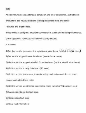
2:Function:
1)Get the vehicle to support the activities of data items (data flow item)
2)Get vehicle support freeze data items (freeze frame items)
3) Get the vehicle support vehicle information items (vehicle identification items)
4) Get the vehicle activity data items (90 more)
5) Get the vehicle freeze data items (including malfunction code freeze frame
storage and related field data)
6) Get the vehicle identification information items (vehicles VIN number, etc.)
7) has decided to get the fault code
8) Get pending fault code
9) Clear fault information

10) hard acceleration monitoring
11) rapid deceleration monitoring (brakes)
12) Parking is not flame monitoring (alarm)
13) Battery voltage monitoring (automatic low voltage alarm)
14) trip mileage statistics
15) trip fuel consumption statistics
16) Travel time statistics
17) to get the total mileage of the vehicle
18) to obtain instantaneous fuel consumption of vehicles
19) reading device parameters (model, displacement, mileage, low-voltage
threshold, parking is not flame threshold, alarm control ...)
20) set the device parameters (models, displacement, mileage, low-voltage
threshold, parking is not flame threshold, alarm control ...)
21) Other extensions
3. product protocol support
This product is a communication protocol for the international standard with the
car,including as follows:

1) SAE_ J1850_VPW
2) SAE_J1850_PWM
3) ISO_15765_STD_500
4) ISO_15765_EXT_500
5) ISO_15765_STD_250
6) ISO_15765_EXT_250
7) ISO_9141_08_Init
8) ISO_9141_94_Init
9) ISO_14230_Slow_Init
10) ISO_14230_Fast_Init
4. Inteface means
OBDII J1962 connector meets standards, can be mounted directly to the vehicle
OBD diagnostic seat to use.
OBD diagnostic seat vehicle signal is defined as follows:
Pin 2 - J1850 Bus+(VPW/PWM)
Pin 4 - Chassis Ground
Pin 5 - Signal Ground

Pin 6 - CAN High (CANBUS)
Pin 7 - ISO 9141-2 K Line(ISO9141-2/KWP2000)
Pin 10 - J1850 Bus-(PWM)
Pin 14 - CAN Low (CANBUS)
Pin 15 - ISO 9141-2 L Line(ISO9141-2/KWP2000)
Pin 16 - Battery Power
● Communication Interface Definition
Using serial communications, serial port level is TTL / CMOS (3.3V), the pin is
defined as follows:
1 red wire, power supply positive output, DC12V
2 white wire, serial data output, TxD
3 blue line, serial data input, RxD
4 black lines, power ground, GND
6 Technical parameters
Voltage DC9 ~ 16V
Current 35mA (normal) <10mA (standby)

Operating temperature -20 ℃ ~ +70 ℃
Storage temperature -40 ℃ ~ +85 ℃
Technical Documentation 5__
6: The OBD data is upload the platform by GPRS,and you can see this info. As like the photo:

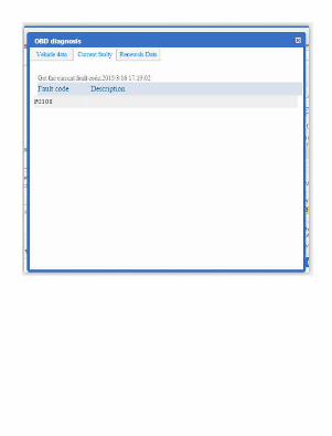

The mobile APP also support real time check the OBD data: