Embed Size (px)
Citation preview
1
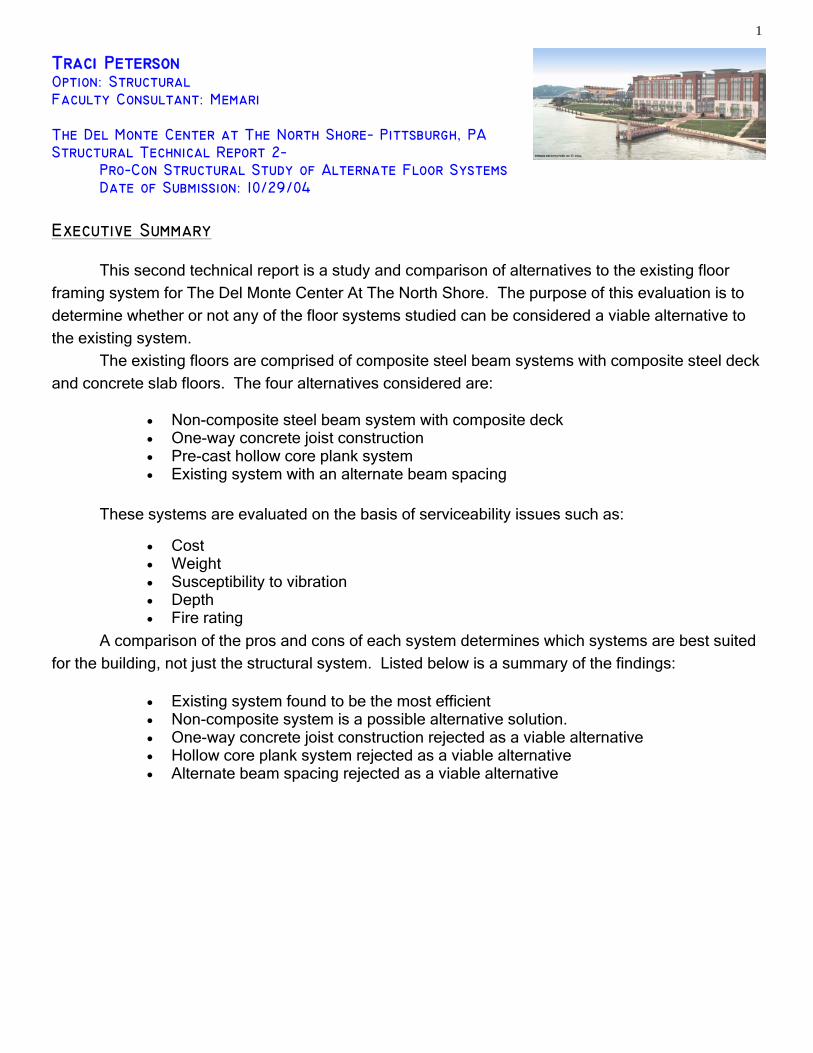
Traci Peterson Option: Structural Faculty Consultant: Memari The Del Monte Center at The North Shore− Pittsburgh, PA Structural Technical Report 2− Pro−Con Structural Study of Alternate Floor Systems Date of Submission: 10/29/04
• Non-composite steel beam system with composite deck • One-way concrete joist construction • Pre-cast hollow core plank system • Existing system with an alternate beam spacing
• Cost • Weight • Susceptibility to vibration • Depth • Fire rating
Executive Summary This second technical report is a study and comparison of alternatives to the existing floor framing system for The Del Monte Center At The North Shore. The purpose of this evaluation is to determine whether or not any of the floor systems studied can be considered a viable alternative to the existing system. The existing floors are comprised of composite steel beam systems with composite steel deck
and concrete slab floors. The four alternatives considered are:
These systems are evaluated on the basis of serviceability issues such as: A comparison of the pros and cons of each system determines which systems are best suited
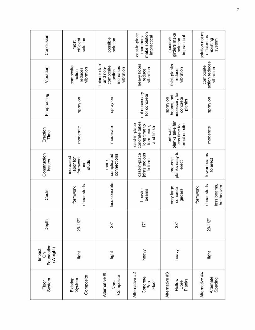
for the building, not just the structural system. Listed below is a summary of the findings:
• Existing system found to be the most efficient • Non-composite system is a possible alternative solution. • One-way concrete joist construction rejected as a viable alternative • Hollow core plank system rejected as a viable alternative • Alternate beam spacing rejected as a viable alternative
2
W18x35
W18x40
W18x40
W18x40
w24x6
2
w24x6
2
2
3
c b
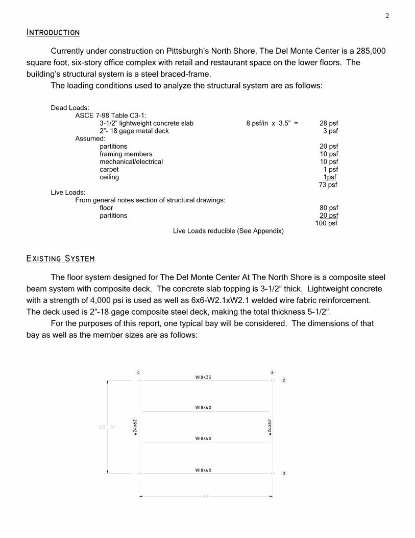
Existing System The floor system designed for The Del Monte Center At The North Shore is a composite steel
beam system with composite deck. The concrete slab topping is 3-1/2” thick. Lightweight concrete
with a strength of 4,000 psi is used as well as 6x6-W2.1xW2.1 welded wire fabric reinforcement.
The deck used is 2”-18 gage composite steel deck, making the total thickness 5-1/2”.
For the purposes of this report, one typical bay will be considered. The dimensions of that
bay as well as the member sizes are as follows:
Introduction Currently under construction on Pittsburgh’s North Shore, The Del Monte Center is a 285,000 square foot, six-story office complex with retail and restaurant space on the lower floors. The building’s structural system is a steel braced-frame. The loading conditions used to analyze the structural system are as follows: Dead Loads: ASCE 7-98 Table C3-1: 3-1/2” lightweight concrete slab 8 psf/in x 3.5” = 28 psf 2”- 18 gage metal deck 3 psf Assumed: partitions 20 psf framing members 10 psf mechanical/electrical 10 psf carpet 1 psf ceiling 1psf 73 psf Live Loads: From general notes section of structural drawings: floor 80 psf partitions 20 psf 100 psf Live Loads reducible (See Appendix)
3
W 8 x 18
W 8 x 13
W 8 x 13
W 8 x 18
w24
x55
w24
x55
2
3
c b
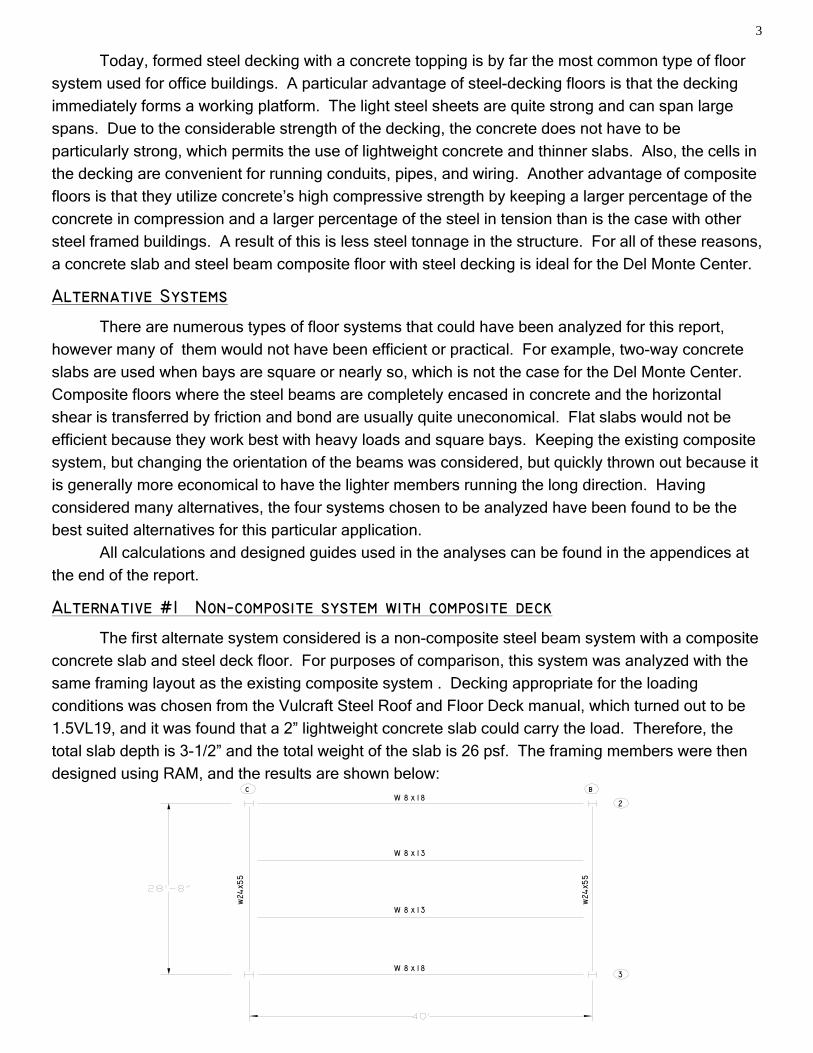
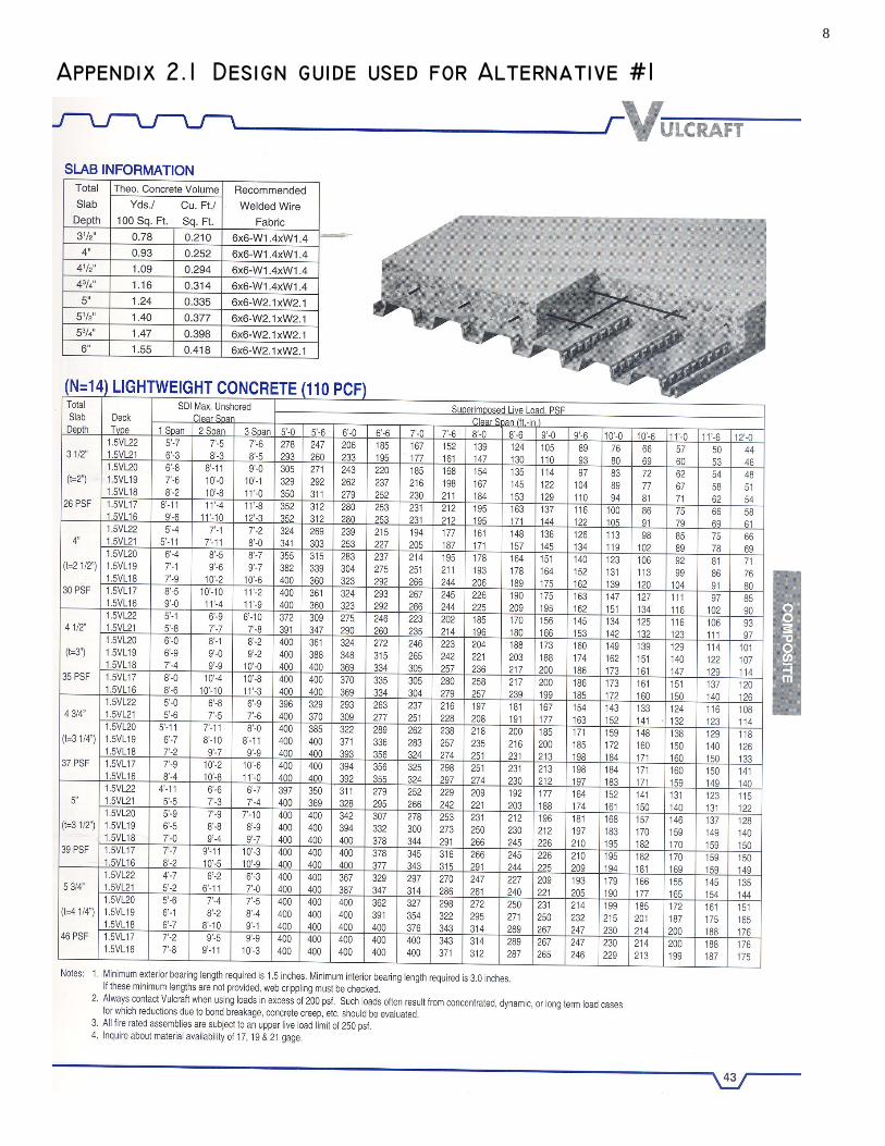
Alternative #1 Non−composite system with composite deck
The first alternate system considered is a non-composite steel beam system with a composite
concrete slab and steel deck floor. For purposes of comparison, this system was analyzed with the
same framing layout as the existing composite system . Decking appropriate for the loading conditions was chosen from the Vulcraft Steel Roof and Floor Deck manual, which turned out to be 1.5VL19, and it was found that a 2” lightweight concrete slab could carry the load. Therefore, the total slab depth is 3-1/2” and the total weight of the slab is 26 psf. The framing members were then
designed using RAM, and the results are shown below:
Today, formed steel decking with a concrete topping is by far the most common type of floor system used for office buildings. A particular advantage of steel-decking floors is that the decking immediately forms a working platform. The light steel sheets are quite strong and can span large spans. Due to the considerable strength of the decking, the concrete does not have to be particularly strong, which permits the use of lightweight concrete and thinner slabs. Also, the cells in the decking are convenient for running conduits, pipes, and wiring. Another advantage of composite floors is that they utilize concrete’s high compressive strength by keeping a larger percentage of the concrete in compression and a larger percentage of the steel in tension than is the case with other steel framed buildings. A result of this is less steel tonnage in the structure. For all of these reasons, a concrete slab and steel beam composite floor with steel decking is ideal for the Del Monte Center.
Alternative Systems
There are numerous types of floor systems that could have been analyzed for this report, however many of them would not have been efficient or practical. For example, two-way concrete
slabs are used when bays are square or nearly so, which is not the case for the Del Monte Center.
Composite floors where the steel beams are completely encased in concrete and the horizontal
shear is transferred by friction and bond are usually quite uneconomical. Flat slabs would not be
efficient because they work best with heavy loads and square bays. Keeping the existing composite
system, but changing the orientation of the beams was considered, but quickly thrown out because it
is generally more economical to have the lighter members running the long direction. Having
considered many alternatives, the four systems chosen to be analyzed have been found to be the best suited alternatives for this particular application.
All calculations and designed guides used in the analyses can be found in the appendices at
the end of the report.
4
top bars = #5 @ 11"
bottom bars = 2#5
2
3
c b35"x17"
35"x17"
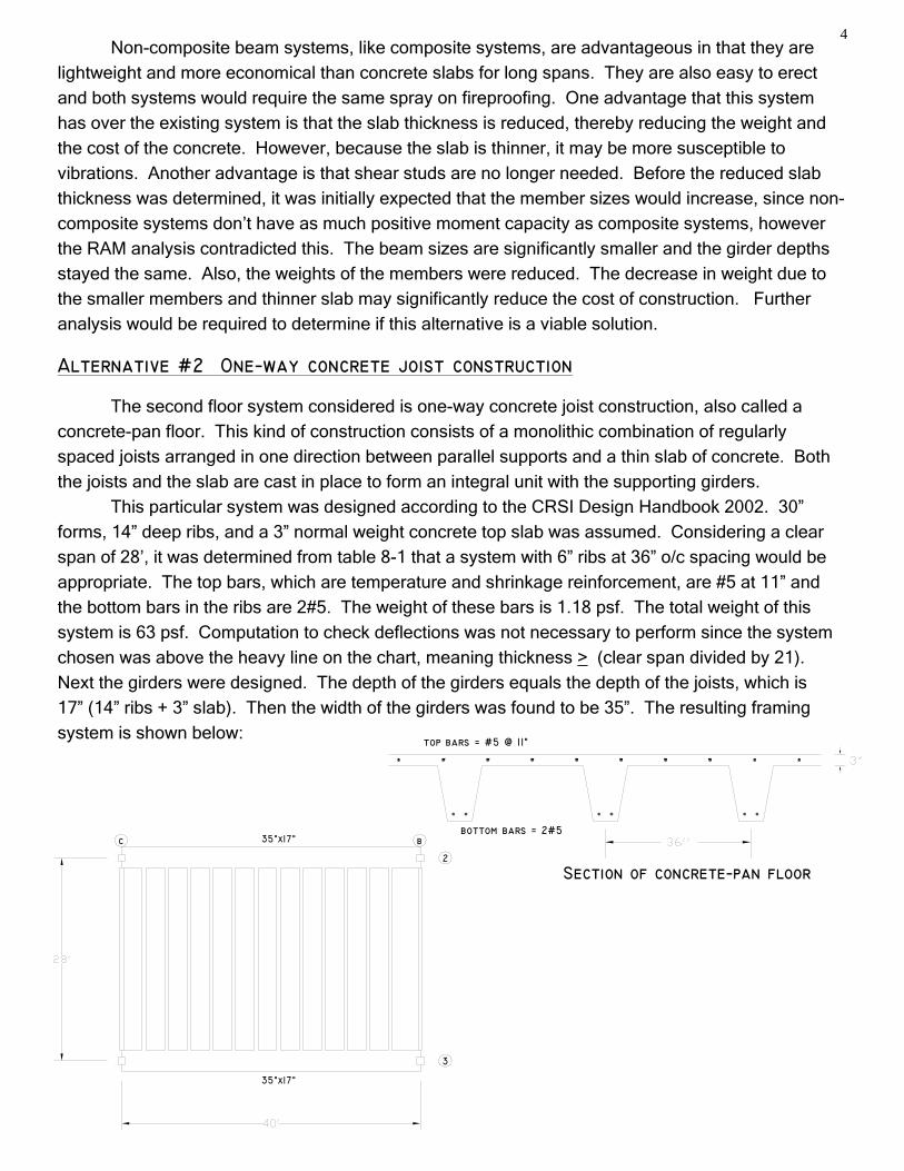
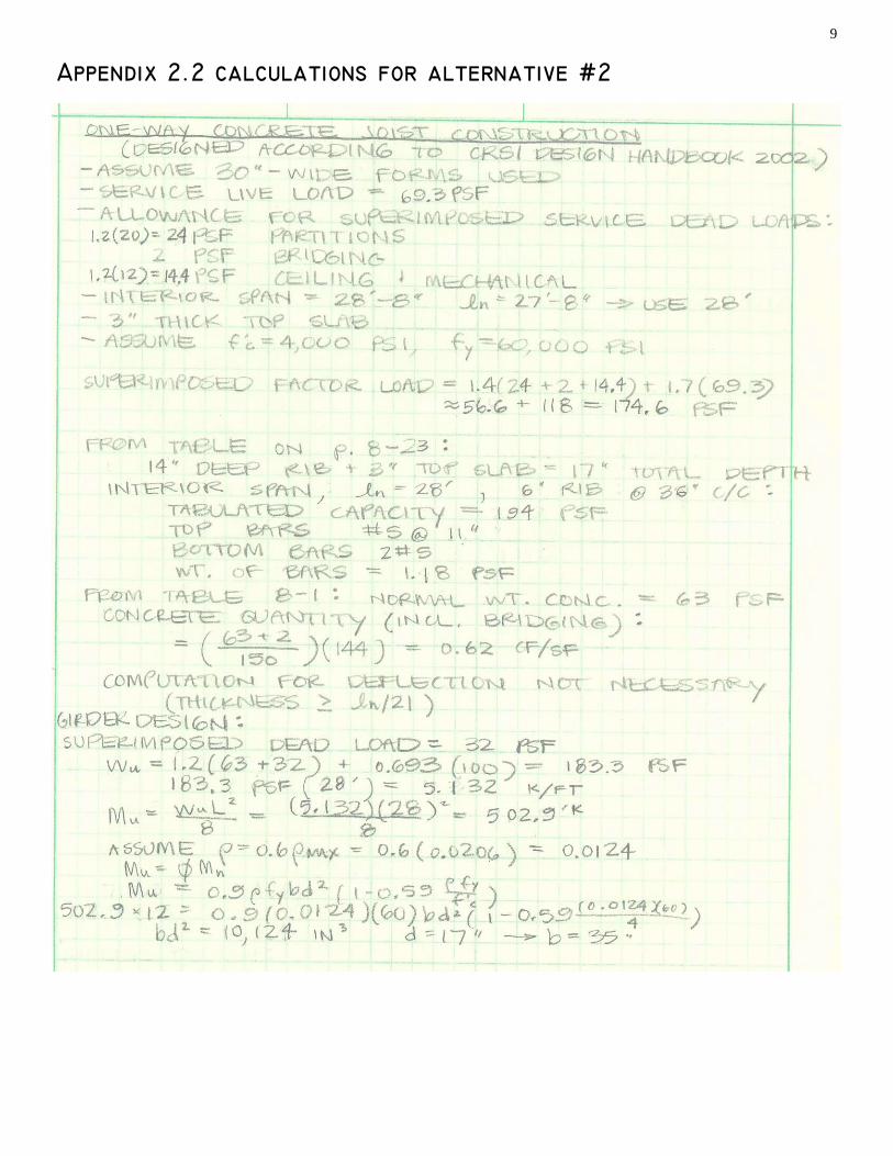
Alternative #2 One−way concrete joist construction The second floor system considered is one-way concrete joist construction, also called a
concrete-pan floor. This kind of construction consists of a monolithic combination of regularly
spaced joists arranged in one direction between parallel supports and a thin slab of concrete. Both
the joists and the slab are cast in place to form an integral unit with the supporting girders.
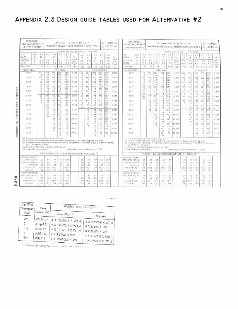
This particular system was designed according to the CRSI Design Handbook 2002. 30”
forms, 14” deep ribs, and a 3” normal weight concrete top slab was assumed. Considering a clear
span of 28’, it was determined from table 8-1 that a system with 6” ribs at 36” o/c spacing would be
appropriate. The top bars, which are temperature and shrinkage reinforcement, are #5 at 11” and
the bottom bars in the ribs are 2#5. The weight of these bars is 1.18 psf. The total weight of this
system is 63 psf. Computation to check deflections was not necessary to perform since the system
chosen was above the heavy line on the chart, meaning thickness > (clear span divided by 21).
Next the girders were designed. The depth of the girders equals the depth of the joists, which is
17” (14” ribs + 3” slab). Then the width of the girders was found to be 35”. The resulting framing
system is shown below:
Non-composite beam systems, like composite systems, are advantageous in that they are lightweight and more economical than concrete slabs for long spans. They are also easy to erect and both systems would require the same spray on fireproofing. One advantage that this system has over the existing system is that the slab thickness is reduced, thereby reducing the weight and the cost of the concrete. However, because the slab is thinner, it may be more susceptible to vibrations. Another advantage is that shear studs are no longer needed. Before the reduced slab thickness was determined, it was initially expected that the member sizes would increase, since non-composite systems don’t have as much positive moment capacity as composite systems, however the RAM analysis contradicted this. The beam sizes are significantly smaller and the girder depths stayed the same. Also, the weights of the members were reduced. The decrease in weight due to the smaller members and thinner slab may significantly reduce the cost of construction. Further analysis would be required to determine if this alternative is a viable solution.
Section of concrete−pan floor
5
W30x99
W30x99
W30x99
w24x6
2
w24x6
2
2
3
c b
8" x 4’ planks
One advantage to one-way concrete joist construction is that there is a high degree of structural redundancy, which lends to the ease of constructability. Also, the pans and formwork used to construct this system can be reused, which increases efficiency. And additional fireproofing is not required. However, cast-in-place concrete takes a long time to form, cure, and finish. This raises the cost and time to construct. And concrete systems are very heavy. This can impact the foundation design. Also, the girders designed for this system are very massive, and they may be impractical. Another aspect to consider is that the lateral system may need to be redesigned
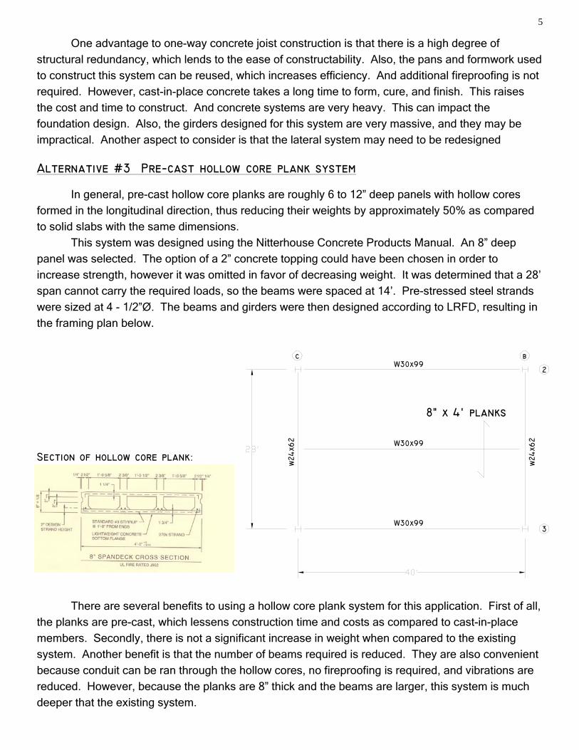
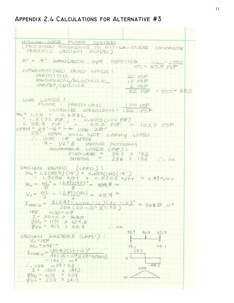
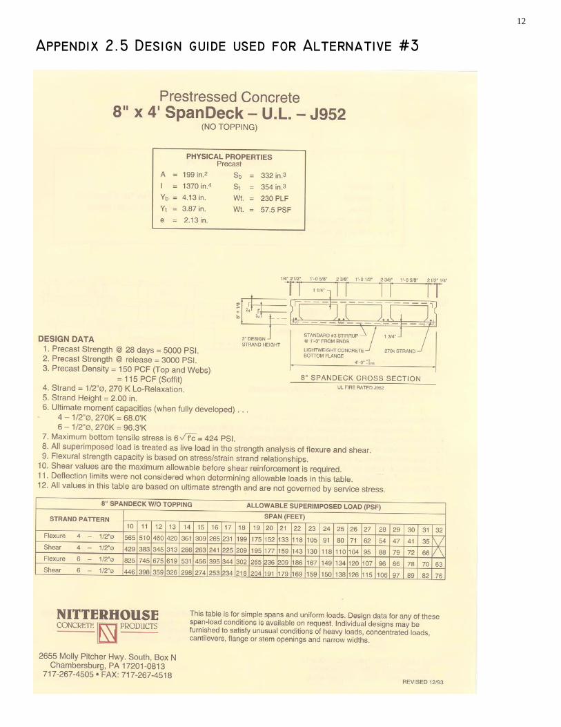
Alternative #3 Pre−cast hollow core plank system In general, pre-cast hollow core planks are roughly 6 to 12” deep panels with hollow cores formed in the longitudinal direction, thus reducing their weights by approximately 50% as compared to solid slabs with the same dimensions. This system was designed using the Nitterhouse Concrete Products Manual. An 8” deep panel was selected. The option of a 2” concrete topping could have been chosen in order to
increase strength, however it was omitted in favor of decreasing weight. It was determined that a 28’
span cannot carry the required loads, so the beams were spaced at 14’. Pre-stressed steel strands
were sized at 4 - 1/2ӯ. The beams and girders were then designed according to LRFD, resulting in
the framing plan below.
There are several benefits to using a hollow core plank system for this application. First of all,
the planks are pre-cast, which lessens construction time and costs as compared to cast-in-place members. Secondly, there is not a significant increase in weight when compared to the existing system. Another benefit is that the number of beams required is reduced. They are also convenient because conduit can be ran through the hollow cores, no fireproofing is required, and vibrations are
reduced. However, because the planks are 8” thick and the beams are larger, this system is much deeper that the existing system.
Section of hollow core plank:
6
W30x90
W30x90
W30X90
w21x
48
w21x
48
2
3
c b
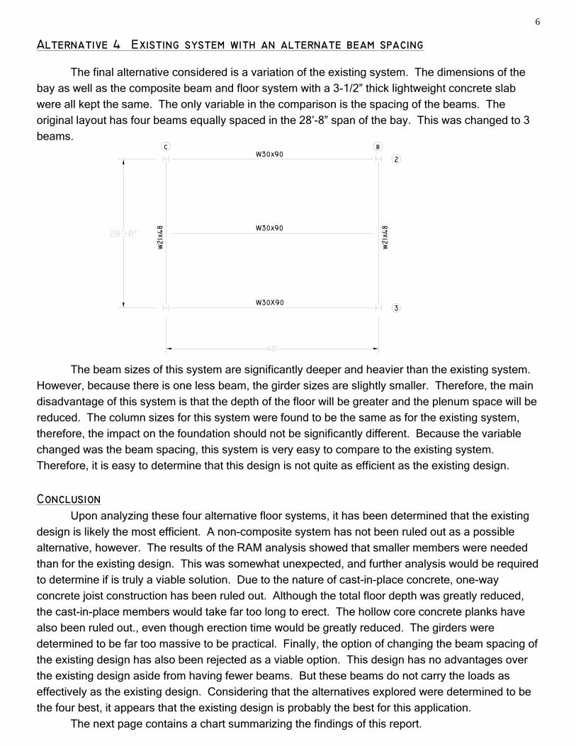
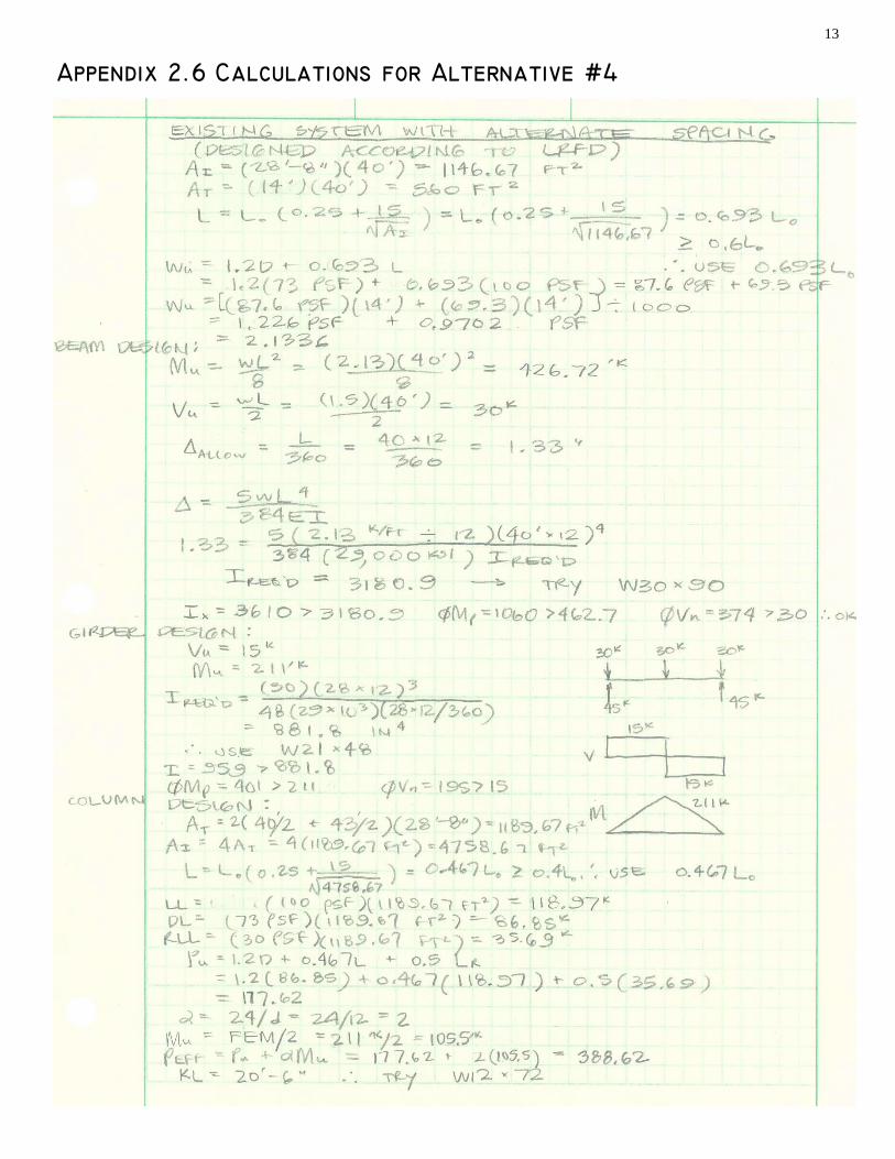
Alternative 4 Existing system with an alternate beam spacing The final alternative considered is a variation of the existing system. The dimensions of the bay as well as the composite beam and floor system with a 3-1/2” thick lightweight concrete slab were all kept the same. The only variable in the comparison is the spacing of the beams. The original layout has four beams equally spaced in the 28’-8” span of the bay. This was changed to 3 beams.
The beam sizes of this system are significantly deeper and heavier than the existing system.
However, because there is one less beam, the girder sizes are slightly smaller. Therefore, the main
disadvantage of this system is that the depth of the floor will be greater and the plenum space will be
reduced. The column sizes for this system were found to be the same as for the existing system,
therefore, the impact on the foundation should not be significantly different. Because the variable
changed was the beam spacing, this system is very easy to compare to the existing system.
Therefore, it is easy to determine that this design is not quite as efficient as the existing design.
Conclusion Upon analyzing these four alternative floor systems, it has been determined that the existing design is likely the most efficient. A non-composite system has not been ruled out as a possible
alternative, however. The results of the RAM analysis showed that smaller members were needed than for the existing design. This was somewhat unexpected, and further analysis would be required to determine if is truly a viable solution. Due to the nature of cast-in-place concrete, one-way concrete joist construction has been ruled out. Although the total floor depth was greatly reduced, the cast-in-place members would take far too long to erect. The hollow core concrete planks have
also been ruled out., even though erection time would be greatly reduced. The girders were determined to be far too massive to be practical. Finally, the option of changing the beam spacing of the existing design has also been rejected as a viable option. This design has no advantages over
the existing design aside from having fewer beams. But these beams do not carry the loads as effectively as the existing design. Considering that the alternatives explored were determined to be the four best, it appears that the existing design is probably the best for this application. The next page contains a chart summarizing the findings of this report.
7
Flo
or
Sys
tem
Impa
ct
On
F
ound
atio
n (W
eigh
t)
Dep
th
Cos
ts
Con
stru
ctio
n Is
sues
E
rect
ion
Tim
e F
irepr
oofin
g V
ibra
tion
Con
clus
ion
Exi
stin
g S
yste
m
C
ompo
site
light
29
-1/2
” fo
rmw
ork
sh
ear
stud
s
incr
ease
d
labo
r fo
r
form
wor
k an
d st
uds
mod
erat
e sp
ray
on
com
posi
te
actio
n
redu
ces
vi
brat
ion
mos
t ef
ficie
nt
solu
tion
Alte
rnat
ive
#!
N
on-
Com
posi
te
light
28
” le
ss c
oncr
ete
mor
e co
mpl
icat
ed
conn
ectio
ns
mod
erat
e sp
ray
on
thin
ner
slab
an
d no
n-co
mpo
site
ac
tion
incr
ease
s vi
brat
ion
poss
ible
so
lutio
n
Alte
rnat
ive
#2
C
oncr
ete
Pan
F
loor
heav
y 17
” he
avie
r be
ams
cast
-in-p
lace
jo
ists
tedi
ous
to fo
rm
cast
-in-p
lace
co
ncre
te ta
kes
long
tim
e to
fo
rm, c
ure,
an
d fin
ish
not n
eces
sary
fo
r co
ncre
te
heav
y flo
ors
redu
ce
vibr
atio
n
cast
-in-p
lace
m
embe
rs
mak
e so
lutio
n im
prac
tical
Alte
rnat
ive
#3
H
ollo
w
Cor
e P
lank
s
heav
y 38
” ve
ry la
rge
conc
rete
gi
rder
s
pre-
cast
pl
anks
eas
y to
er
ect
pre-
cast
pl
anks
take
far
less
tim
e to
er
ect o
n-si
te
spra
y on
be
ams,
not
ne
cess
ary
for
conc
rete
pl
anks
thic
k pl
anks
re
duce
vi
brat
ion
mas
sive
gi
rder
s m
ake
solu
tion
impr
actic
al
Alte
rnat
ive
#4
A
ltern
ate
Spa
cing
light
29
-1/2
”
form
wor
k
shea
r st
uds
le
ss b
eam
s,
but h
eavi
er
few
er b
eam
s to
ere
ct
mod
erat
e sp
ray
on
com
posi
te
actio
n re
duce
s vi
brat
ion
solu
tion
not a
s ef
ficie
nt a
s ex
istin
g sy
stem
8
Appendix 2.1 Design guide used for Alternative #1
9
Appendix 2.2 calculations for alternative #2
10
Appendix 2.3 Design guide tables used for Alternative #2
11
Appendix 2.4 Calculations for Alternative #3
12
Appendix 2.5 Design guide used for Alternative #3
13
Appendix 2.6 Calculations for Alternative #4