Embed Size (px)
Citation preview

| February March 2006 | Volume 24 Number 1
Trail building: Trendsin erosion control
Trail building: Trendsin erosion control
Brownfi eldsuccess in Oshkosh
Saving Prospect Lake
Richardson reminisces onWW II airfi eld engineering
Brownfi eldsuccess in Oshkosh
Saving Prospect Lake
Richardson reminisces onWW II airfi eld engineering
Subscribe at www.geosyntheticsmagazine.info
0206Geosyn_Cv1.indd 10206Geosyn_Cv1.indd 1 2/2/06 9:18:23 AM2/2/06 9:18:23 AM
14 | World War II engineers built airfields from thePacific islands to North Africa to Normandy usingprecursors to today’s geosynthetic materials.
EditorialSame magazine, new look
Panorama Award-winning erosion-control matsGeofoam in IowaInternational Achievement Awards
Designer’s ForumLost in history: “Geo-Airdromes”By Gregory Richardson
TerminologyChanging terms in the geosynthetics worldBy Helmut Zanzinger and Robert Mackey
Geosynthetic InstituteBoard of Directors
Calendar
Advertiser Index
| In Situ |
Project ShowcaseConstruction at a regional airport in Missouri andbaffle-curtain usage at a paper mill in Mississippishowcase geosynthetics.
Happy Trails: Erosion control andeffective drainageBy Kathy ShepardProper horse trail performance beginswith design, not repairs.
Engineering brownfield redevelopmentBy Patrick Grogan, and Paul TimmA geosynthetic clay liner barrier helps correct100+ years of pollution.
The formation of ochre biofilm ingeotextile filtersBy Marcos Barreto Mendonça, Mauricio Ehrlich,and Magali Christe CammarotaA closer look at drainage performance at the interfaceof aerated and non-aerated environments.
Saving Prospect LakeBy Stanford Slifer, Greg Monley,Kyle Hier, and Timothy StarkPVC geomembranes help restorea Colorado Springs landmark.
| On Site |
22
26
30
34
44
Making the world betterBy Ron Bygness, Editor, Geosynthetics (formerly GFR)
| Final Inspection |
56
30 | Redevelopment at this brownfield site included design of a GCL trench.
44 | A rejuvenated Prospect Lake was the result of this project.
| February March 2006 |volume 24 | number 1
2 www.geosyntheticsmagazine.info
Geo
synt
hetic
s Fe
brua
ry M
arch
200
6
26 | On the coverThis trail project in Ohio includedgeocell installation. See page 26.Cover design by Heidi Hanson.
Coming Next Issue | Greenroofs | Retaining walls | Agriculture | Private development | Infrastructure | Services
4
6
14
52
54
5557

With this issue, Geosynthetics (formerly GFR) enters its next growth phase. The magazine, originally titled Geotechnical Fabrics Report, published its first issue in the summer of 1983, less than a year after theSecond International Conference on Geotextiles, Las Vegas, and a few months before the International Geotextile Society’s (IGS) founding. As technologies expanded and terminology settled, the term “geosynthetics” was adopted to encompass the engineering field’s many product categories, such as geocells, geogrids, and geomembranes.
IGS became the International Geosynthetics Society (IGS). GFRcontinued with its original name, but the magazine’s publisher, the Indus-trial Fabrics Association International (IFAI), established the biennial Geosynthetics conference series (1987, New Orleans) with the IGS. Soon
thereafter, IFAI’s Geotextile and Geomembrane Divisions merged to form the Geosynthetic Materials Association (GMA).
The IGS and GMA continueto be vital organizations whose
members contribute a tremendous amount to the engineering community through conferences; funded research; and technology transfer through pub-lication of news articles, project case studies, and commentaries. This has, in turn, produced many contributions from the larger engineering community that plans, designs, installs, and constructs with geosynthetic materials.
Geosynthetics has been the product of this dialogue, and it has been a successful one. In the past year, the magazine won two awards for technical/scientific articles and one for the annual Specifier’s Guide. The magazine owes its success to the involvement, advice, and contributions of its readers.
This year, we’ve adopted (finally) the field’s umbrella term, Geosynthet-ics, and we’ve redesigned the front cover and interior look. We’re proud of these updates, and we look forward to the ever-evolving dialogue with our readers, our writers, and the organizations whose members provide theessential funding and events that help us grow.
Same magazine,new look
| Editorial |
| Susan Niemi, Editorial Director+1 651 225 [email protected]
| Geosynthetics encourages your contributions of case histories, photos and field tips. For submittal guidelines, contact
Ron Bygness at 800 225 4324 or +1 651 225 6988; e-mail: [email protected].
4 www.geosyntheticsmagazine.info
Geo
synt
hetic
s Fe
brua
ry M
arch
200
6
EDITORIAL ADVISORY COMMITTEE*
Melody A. AdamsEMCON/OWT Inc., USA
Sam R. AllenTRI/Environmental, USA
Richard J. BathurstRoyal Military College, Canada
Witty BindraPermathene Pty. Ltd., Australia
David A. CarsonU.S. EPA, USA
Daniele A. CazzuffiCESI Spa, Italy
Oscar R. CouttelancGMA, Mexico
Ronald K. FrobelR.K. Frobel & Associates, USA
Stephan M. GaleGale-Tec Engineering Inc., USA
Han-Yong JeonINHA University, Korea
Robert M. KoernerThe Geosynthetic Institute, USA
Robert E. MackeyS2L Inc., USA
Kent von MaubeugeNaue GmbH, Germany
Jacek MlynarekSAGEOS, Canada
Dhani NarejoGSE Lining Technology Inc., USA
Roy J. NelsenNorth American Green, USA
Jim OlstaCETCO, USA
Ian D. PeggsI-Corp International, USA
Greg N. RichardsonG.N. Richardson & Associates Inc., USA
Marco A. SánchezML Ingeniería, Mexico
Mark E. SmithVector Engineering, Peru
L. David SuitsNAGS, USA
Gary L. WillibeyAdvanced Drainage Systems, USA
Aigen ZhaoTenax Corp., USA
*The Editorial Advisory Committee reviews selected papers, case histories, and technical editorial copy in its areas of expertise. Individual advisors do not review every submission. Statements of fact and opinion are the author’s responsibility alone, and do not imply the viewpoints of Geosynthetics, its Editorial Advisory Committee, editors, or the association.
Geosynthetics (formerly GFR) is an international, bi-monthly publica-tion for civil engineers, contractors and government agencies in need ofexpert information on geosynthetic engineering solutions. Geosyntheticspresents articles from field professionals for innovative, exemplary practice.
Geosynthetics has been the product of this dialogue, and it has been a successful one.

6 www.geosyntheticsmagazine.info
Geo
synt
hetic
s Fe
brua
ry M
arch
200
6
| Panorama |
2005 BuildingGreen Top-10 featureserosion-control mats
Erosion-control mats from North American Green have been named to the Top-10 Green Bui ld ing Products for 2005, selected by theeditors of GreenSpec® and Environ-
mental Building News.™ These are all products that have been added to GreenSpec during the past year, though some may have been on the market longer. There is additional
information on these products in the online edition of GreenSpec, which is available by subscription as part of the BuildingGreen Suite (www.BuildingGreen.com).
BioNet erosion-control matsfrom North American Green
Erosion control is an important issue both on job sites and with ecological restoration projects. North American Green has been a leader in erosion-control products. Though
the 100% biodegradable BioNet® series oferosion-control mats have been around a long time (since 1993), this product was new to the GreenSpec Directory in 2005. BioNet mats have a core of straw or straw and coir(coconut fiber) held by woven jute net-ting and stitched with cotton thread. The mats are secured to the ground with bio-degradable stakes made of either corn-derived polylactic acid (PLA) or wood. The
company also makes erosion-control mats held together with photodegradable polypropylene, but these products are far less biodegradable than the natural fibers used in BioNet.
What makes this product green?• Agricultural waste material• Rapidly renewable products• Reduces pollution or waste from operations• Reduces construction impacts
LEED Credit relevance:• SS Prereq. 1 - Erosion and Sedimentation• MR Credit 6 - Rapidly Renewable Materials
Product information:North American Green14649 Highway 41 NorthEvansville, IN 47725Phone: 800 772 2040, 812 867 6632Fax: 812 867 0247www.nagreen.com
Media contact:Lynne FinneyMarketing ManagerNorth American Green+1 812 867 6632 x315;e-mail: [email protected]
Photos courtesty of North American Green
| Panorama |
8 www.geosyntheticsmagazine.info
Geo
synt
hetic
s Fe
brua
ry M
arch
200
6
| Professor Fumio Tatsuoka is the IGS vice president and chair of the 8ICG
Organizing Committee. Visit the conference Web site at www.8icg-yokohama.org.
Karina McInnis, editor of IGS News, arranged publication of this update.
Update: 8 ICG
By Fumio Tatsuoka
More than 400 paper abstracts have been accepted for the 8th International Conference on Geosynthetics (8ICG)—the largest number in the history of the International Conferences on Geosyn-thetics. The final papers will be peer-reviewed by the International PaperSelection Committee (IPSC). The con-ference will be held 18-22 September, 2006, in Yokohama, Japan.
Conference topics• Transport (roads, railways, tunnels,
airports, etc.)• Hydraulic structures (dams, canals,
reservoirs, etc.)• Erosion control and coastal works• Soil improvement and reinforcement• Mining• Waste landfills• Remediation of contaminated sites• Landscaping and environmental
mitigation• Prevention of natural and
technological risks• Agriculture and forests• Innovative geomaterials and
construction methods• Education and technology transfer
A special plenary session will be held during the 8ICG to help facilitate a dia-logue between geosynthetic researchers and practitioners. Richard J. Bathurst, International Geosynthetics Society (IGS) Past-President, will moderate. The goal is to have areas of research identi-fied by academics that have potential applications to practitioners and have potential geosynthetics research oppor-tunities identified by practitioners.
Case historiesA new and unique feature of 8ICG
will be sessions organized for more than 80 papers on geosynthetic engineering case histories that have been submitted by IGS chapters all over the world.
Special and keynote lectures• Giroud Lecture by C.R. Lawson (Ma-
laysia) on “Geotextile Containment: Old and New.”
• Keynote lecture by M. Heibaum (Germany), A. Fourie (Austra-lia), H. Girard (France), G.P.Karunaratne (Singapore), J. Laf-leur (Canada), and E.M. Palmeira (Brazil) on “Hydraulic Applicationsof Geosynthetics.”
• Keynote lecture by J. Koseki (Japan), R.J. Bathurst (Canada), E. Guler (Turkey), J. Kuwano (Japan), and M. Maugeri (Italy) on “Seismic Stability of Reinforced Soil Walls.”
• Keynote lecture by E. Kavazanjian (USA), H. Zanziger (Germany), P. Legg (South Africa), and A. Kor-tegast (New Zealand) on “Landfill and Environmental Issues.”
Keynote lecture by J.P. Giroud on “IGS History.”
Other Activities and EventsFollowing the tradition of the
past ICGs, an exhibition will also be held.
Excursions to various attractions in Kyoto and the surrounding area are planned. These will enable confer-ence participants and accompanying persons an opportunity to enjoy Japa-nese culture, including visits to modern and historical cities and a cruise on Tokyo Bay. Also, a number of post-conference technical tours to unique and interesting construction sites and structures are being organized.
Conference registration has already started. Visit the conference Web site at www.8icg-yokohama.org for more information on transportation, accom-modation, registration, and exhibitor applications; or contact the confer-ence secretary, Noboru Kiyokawa, 8th ICG, Yokohama 2006, Ueno TH Building 7F, 3-39-10 Yoshima, Bun-kyo-ku, Tokyo 113-0034, Japan; +81 3 3837 2503, fax +81 3 3837 5818, e-mail [email protected].
New location for PWT’s Eastern office
The Eastern States office of Plas-tic Welding Technologies (PWT) has relocated to Pittsburgh. Formerly in West Virginia, this PWT office is now at: 401 Parkway View Dr., Pittsburgh, PA 15205.
Rick Conrad is the primary contact in this office. He can be reached at: 888 793 7333, +1 412 787 9800, [email protected].
PWT’s Western States office remains at 6125 Enterprise Dr., #10, Diamond Springs, CA 95619. The main contact person is Greg Yaple: 800 635-6693,+1 530 622 2791.
Propex Fabrics acquires SI Corp.
Propex Fabrics Inc., SI Concrete Systems Corporation, and SI Geo-solutions Corporation (SI) haveannounced an agreement whereby Propex will purchase SI.
Ed Stanczak will remain CEO and president of the combined entity. Company headquarters will be re-located to northern Atlanta, where growing the companies’ international presence will be a priority.
According to Stanczak, “It is their intention to create a highly diversi-fied and balanced company which will become the best of the best. Theintended combination is a classic ex-ample of two good companies combin-ing to become one great company.
“This will be great for customers, em-ployees, shareholders, and suppliers.”
Joe Dana, current CEO of SI, will become the president of North American Operations, with its head-quarters located in Chattanooga, Tenn. Dana commented: “The com-bination will create opportunities to leverage the capabilities of each organization to optimize operations and generate profitable growth.
“They will continue to be market driven and innovation focused with special emphasis on maintainingex-ceptional service to all customers.”
The combined entity will be one of the world’s leading producers of poly-

| Panorama |
From Bend to BTLOregon-based Bend Tarp and Liner
has expanded again, this time prompt-ing a name change. The 25-year-old firm has changed its name to BTL Inc. in anticipation of opening a new facility outside of the city of Bend. The new Prineville location will offer 63,000 ft.2 (5,850 m2) of production space with an additional 40,000 ft.2 (3,715 m2) for covered storage. The site will allow further expansion too.
BTL’s clear fabrication area will now be 100 by 485 ft. The new facility will allow the company to continue producing its large single panel PPL®
24 and PPL® 30 mil liners up to 60,000 ft.2 (5,575 m2).
The company’s Web site, www.bendtarp.com, will remain unchanged.
For more information, contact BTL Inc., 20845 Sockeye Pl., Bend, OR 97701, United States; +1 541 388 0712, fax +1 541 388 0759, e-mail [email protected], Web site www.bendtarp.com.
propylene-based fabrics for primary and secondary carpet backing, geo-synthetics applications, and a variety of other industrial end uses.
The acquisition was completed January 31, 2006.
Iowa road company builds on success
Cedar Valley Corp., a Waterloo, Iowa-based highway construction firm, has paved new roads for itself with national awards.
The company won two national awards from the American Con-crete Paving Association: one for aninnovative divided highway project in Sioux County in northwest Iowa, the other for a an overlay project on a county “farm-to-market” road in Wapello County in southeast Iowa.
The Sioux County project, man-aged by CV’s Craig Hughes, was a U.S. Highway 60 bypass of Alton, part of a four-lane extension north from Sioux City and Le Mars to the Minnesota border. It utilized lightweight geofoam—large light-weight bricks of highly compressed foam sealed with plastic geomem-brane liners—as fill material and a
weather-resistant covering for part of the project.
“Your diligence in placing the geofoam for lightweight fill made its first-time use by the Iowa Depart-ment of Transportation a hugesuccess,” Iowa DOT engineer Darwin L. Bishop wrote in nominating Cedar Valley for the award.
Bishop also praised Cedar Valley for protecting the environment when it located a concrete plant site in an area designated for wetlands as part of the project.
“After much consideration, it was determined that we would allow your plant site to use this location with strict guidelines,” Bishop wrote. “At the completion of the project the plant site was removed without any major impact to the area. This site alone is evidence of Cedar Valley’s concern for the environment and the communities in which it works.”
It is the first time Cedar Valley has won an award in the “divided high-way rural” category, Cedar Valley vice president Willie Calderwood said.
Significant hurdles included nine bridges, extensive spring rains, and the first-time use of geofoam, Hughes said.
More geosynthetics in Africa
Note: In its October/November issue, Geosynthetics will examine the use ofgeosynthetic materials in Africa’s agriculture and transportation sectors. To contrib-ute project or business information, contact the editor at [email protected].
WASEW Technologies and the Ethiopian government have estab-lished a new plant in the nation’s capital, Addis Ababa. In the last few years, Ethiopia has bought $10 mil-lion–15 million worth of geomem-branes for agricultural use. Also, the country has purchased large quanti-ties of pipe for various applications.
The new company, Geosynthetic Industrial Works PLC, has built a factory with 43,055 ft.2 (4000 m2) of production space and 16,145 ft.2 (1500 m2) of offices. The venture is
part of a “Geosynthetics for Africa” initiative. Stage 1 production goals include high-density polyethylene (HDPE) pipe, polyvinyl chloride (PVC) pipe, HDPE geosynthetic net-ting and geomembranes.
WASEW Technologies is theoperating partner and has a large ownership position. With the estab-lishment of a domestic manufactur-ing source and a government stake in the venture, the opening of the plant is expected to halt the importation of geosynthetics into Ethiopia.
“This is the first award we’ve won on a national level for the kind of work that we do day in and day out,” Calderwood said.
The Wapello County project, near Hedrick, won for concrete overlays. It presented challenges because it spanned two counties—Wapello and Keokuk—and was built under two different county engineering staffs with two different concrete aggregates and two different paving techniques.
In addition, Wapello project man-ager Matt Proctor said work was slowed by nearly unprecedented rainfall in the area. “We had 12 inches of rain in two weeks,” he said. “We could have used a canoe to get from one end of the job to the other in certain places.”
The company also had to maintain access for property owners along the route, including several farms and a trucking company. “Keeping access to people on a county road is dif-ficult when there are no crossroads,” Proctor said.
Since 2001, Cedar Valley has won 26 state and national awards, said CV president and CEO, Steve Jackson.
| Lara Costa of geosynthetica.net contributed this information.
10 www.geosyntheticsmagazine.info
Geo
synt
hetic
s Fe
brua
ry M
arch
200
6
12 www.geosyntheticsmagazine.info
Geo
synt
hetic
s Fe
brua
ry M
arch
200
6
International Achievement AwardsAward of Excellence
Mirafi Construction Products(Ten Cate Geosynthetics)Pendergrass, Ga., United StatesTrump National Golf Club, Los Angeles
Trump National Golf Course is the first and only oceanfront golf course in Los Angeles County. However, a major landslide on 2 June 1999 threatened the course’s future. In the cliff, a 17-acre landslide zone geologically referred to as Ancient Landslide Area C, awoke and robbed the course of most of the 18th hole in a single, rapid event. It was determined that partial removal and re-building of the landward portion of the landslide would achieve the necessary stabilization, cause the least alteration of landforms, and be the most feasible from a geotechnical engineering viewpoint. The final repair plan consisted of four primary steps: (1) improve the stability
of the main slide block with shear pins; (2) open a slot by excavating and removing the upper benton-ite layer and stockpiling the exca-vated materials in a stable area; (3) simultaneously construct the geosynthetic-reinforced mechani-cally stabilized earth (MSE) wall buttress and backfilling the areas behind and in front of the buttress in the open slot using the materials excavated from the adjacent slot; and (4) construct a low permeability clay cap and top soil to the final grade. As a result of the many lay-ers of high-strength geosynthetics used to stabilize the new layers of earth, the hole is now one of the safest places on
the California coast. The club’s owner, Donald Trump, has taken notice. Rarely shy for a sound bite, he’s been quoted in the press as saying, “If I’m ever in Cali-fornia for an earthquake, this is where I want to be standing.”
Project Engineer: Bill Lu, Converse ConsultantsSupplier: White Cap Construction SuppliesFabrication: Mirafi (Ten Cate Geosynthetics)
Installation: Joe Sutter, J.W. Sutter Inc.Geotextiles: Geolon® 600, 300, 200, HS4200, FW404 from Mirafi (Ten Cate Geosynthetics)
Outstanding Achievement Award
Mirafi Construction Products (Ten Cate Geosynthetics)Pendergrass, Ga., United StatesTimmins/Frederick House River Bridge, Timmins, Ontario, Canada
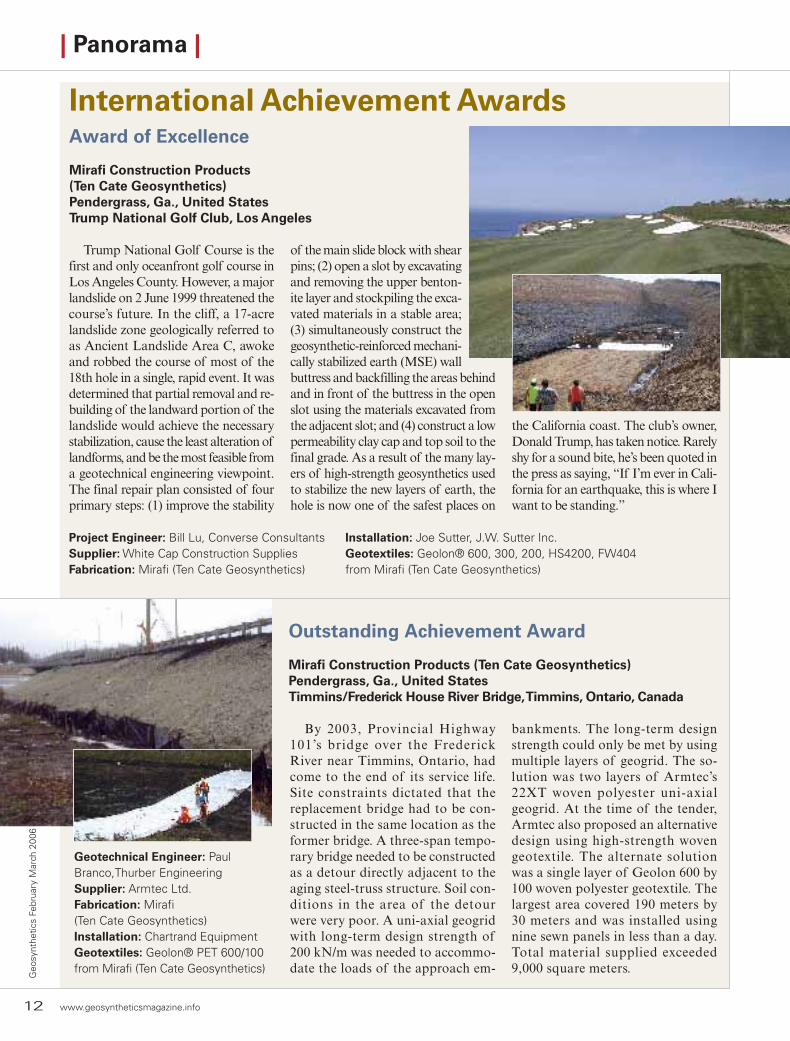
By 2003, Provincial Highway 101’s bridge over the Frederick River near Timmins, Ontario, had come to the end of its service life. Site constraints dictated that the replacement bridge had to be con-structed in the same location as the former bridge. A three-span tempo-rary bridge needed to be constructed as a detour directly adjacent to the aging steel-truss structure. Soil con-ditions in the area of the detour were very poor. A uni-axial geogrid with long-term design strength of 200 kN/m was needed to accommo-date the loads of the approach em-
bankments. The long-term design strength could only be met by using multiple layers of geogrid. The so-lution was two layers of Armtec’s 22XT woven polyester uni-axial geogrid. At the time of the tender, Armtec also proposed an alternative design using high-strength woven geotextile. The alternate solution was a single layer of Geolon 600 by 100 woven polyester geotextile. The largest area covered 190 meters by 30 meters and was installed using nine sewn panels in less than a day. Total material supplied exceeded 9,000 square meters.
Geotechnical Engineer: Paul Branco,Thurber EngineeringSupplier: Armtec Ltd.Fabrication: Mirafi(Ten Cate Geosynthetics)Installation: Chartrand EquipmentGeotextiles: Geolon® PET 600/100 from Mirafi (Ten Cate Geosynthetics)
| Panorama |

www.geosyntheticsmagazine.info 13
Geosynthetics February M
arch 2006
| Panorama |
Outstanding Achievement Award
Colbond Inc.Enka, N.C., United StatesAthletic Field Drainage, Santa Clarita, Calif.
In April 2004, members of the Hart Union School District in Santa Clarita, Calif., decided to spend $12 million to make the switch to synthetic turf at several high school athletic fields. Overall, 300,000 square feet of turf was installed. But while the synthetic turf greatly reduced maintenance needs, occasional flooding in the Santa Clarita Valley could still do considerable harm. The project team selected Enkaturf Drain, manufactured by Colbond Inc. The drain is a geocomposite made of a 1-inch-thick core of fused nylon fila-ments encapsulated within a geotextile fabric. The 95 percent open structure of the nylon core enables water to flow
freely. The geotextile fabric remains open and porous while holding back rock and soil fines. This allows the core to remain open and unobstructed for maximum flow. The drainage systeminstalls directly on the subgrade beneath the stone base and requires no trench-ing. Despite its light weight, the material can withstand up to 30,000 pounds per square foot without incurring damage.
Landscape architect: Purkiss-RoseTurf Supplier: Sportexe Inc.Geocomposite Supplier:Reed & GrahamGeocomposite: Enkaturf Drain from Colbond Inc.
Note: The Industrial Fabrics Association International (IFAI) invites entries for its IAA competition.For more information about the IAAs, contact Christine Malmgren +1 651 225 6926; [email protected]
| Designer’s Forum |
Having been born immediately fol-lowing the only global war in the his-tory of the world, tales of military adventure often filled our family gath-erings. One particular set of stories always touched the budding engineer in me and provided the root of my interest in geosynthetics. These stories followed my uncle as he moved across the European theater of war mounted, not on a tank, but on a bulldozer. This article provides a glimpse of the role of an unheralded aspect of military
Lost in history: “Geo-Airdromes”From World War II engineer battalions to today’s geosyntheticsBy Gregory Richardson
engineering and the life of individuals who implemented it. It also begs the question of the 30-plus-year interval between the military use of war-in-spired construction devices and their later introduction to civil engineering.
Engineer AviationBattalions (EABs)
At the beginning of World War II, 12 EABs existed to support the con-struction and maintenance of avia-
tion fields for the Army Air Force. The 804th repaired Hickman Airfield in Hawaii after the attack on Pearl Harbor in 1941 and later built Kua-loa Airdrome (airfield) that played an instrumental role in the battle of Mid-way. The 803rd maintained airfields in Bataan and Corregidor before they fell to Japanese troops. Few of the 803rd survived the war.
In the European theater, 16 avia-tion battalions were shipped to Eng-land in 1942 to construct airdromes in
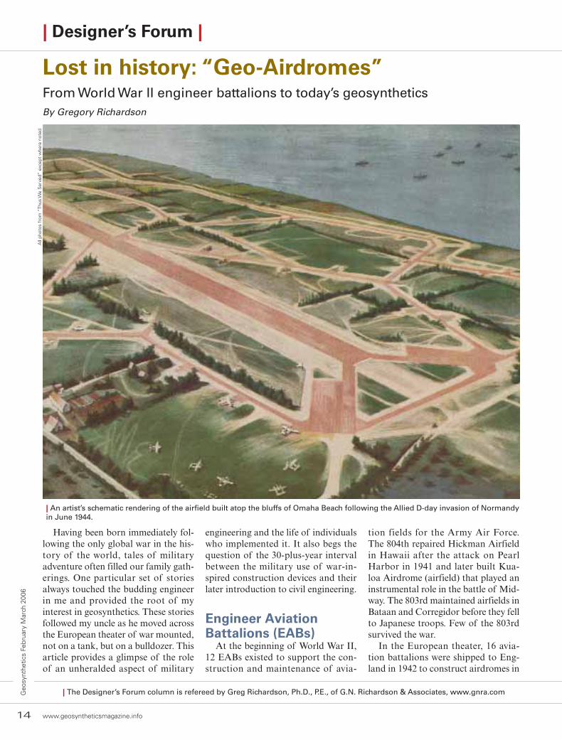
| An artist’s schematic rendering of the airfield built atop the bluffs of Omaha Beach following the Allied D-day invasion of Normandy in June 1944.
| The Designer’s Forum column is refereed by Greg Richardson, Ph.D., P.E., of G.N. Richardson & Associates, www.gnra.com
14 www.geosyntheticsmagazine.info
Geo
synt
hetic
s Fe
brua
ry M
arch
200
6
All
phot
os f
rom
“Th
us W
e S
erve
d” e
xcep
t w
here
not
ed

www.geosyntheticsmagazine.info 15
Geosynthetics February M
arch 2006
| Designer’s Forum |
England to support bombers and to prepare for operations in North Africa and eventually Europe. By December 1942, the number of EABs had grown to 51 worldwide. EABs were staffed with soldiers who had prior engineer-ing or construction experience.
In the battle for North Africa, four EABs were sent to support the air war. Their job was to rapidly repair cap-
tured airfields, construct new strips where needed, and remove mines from those areas. These new fields com-monly began life as Emergency Land-ing Strips (ELSs) to support spotter planes and provide emergency land-ing for damaged planes. Such fields were then upgraded to Refueling and Re-arming Strips (RRSs) to support fighter planes providing cover to ground troops. Such planes then (and today) have limited airtime and must be fueled close to battle if they are to provide adequate cover. Thus, as the fighting front moved, so did the RRS. A few of these fields were then up-graded to Advanced Landing Ground (ALG) to support long-range bomb-ers and stationing of fighters. The engineering requirements, of course, varied for each type of airfield. The EABs experienced notable successes in North Africa, such as the Biskra Airdrome in the Sahara receiving B-17 bombers within 24 hours of the
battalion arriving on site. Problems were experienced in both shipping of equipment and the utility of miniature equipment (compactors, pans, etc.) that had been developed to be flown into remote sites.
By the end of the North African campaign there were 10 EABs and 129 airdromes in action. This campaign provided valuable experience both in
the field and the command structure. Air power was playing an increasingly critical role, yet the integration of the Army Air Force and the EABs into the command and supply structure of the conventional Army was evolving as combat raged. In 1943, EABs par-ticipated in landings in Sicily, quickly establishing the airdromes required to support air cover for an advancing Al-
| Rolling out the “Hessian.”
Their job was to rapidlyrepair captured airfields[and] construct new stripswhere needed.
16 www.geosyntheticsmagazine.info
Geo
synt
hetic
s Fe
brua
ry M
arch
200
6
with grass simply growing through the mesh.
In 1939, the U.S. Army Air Force asked WES to study the European mats and to select or modify one for American planes. Much of this re-search was conducted at WES using heavy vehicle loadings over trial sub-grades built within a large Quonset hut at WES. This same location would be used some 30 years later for nearly identical research using geocells.
WES observed that both types of mesh disintegrated under service and that neither could support largebombers. At a joint industry and gov-ernment meeting, Gerald Greulich of Carnegie-Illinois Steel Corporation sketched out what would become the “pierced steel plank” (PSP) landing mat now familiar to all. After many alterations, the final steel mat was 10 ft. long, 15 in. wide, and ¼-in. thick, weighing 70 lbs. The planks were held together by spring clips and could sup-port a 60,000-lb. bomber.
Since these mats would be deployed worldwide, there was concern about the performance under varying soil conditions. In 1943 and 1944, the WES Flexible Paving Laboratory investi-gated the performance of the PSP mats in fat clays at a site near Mound, La.,
| Designer’s Forum |
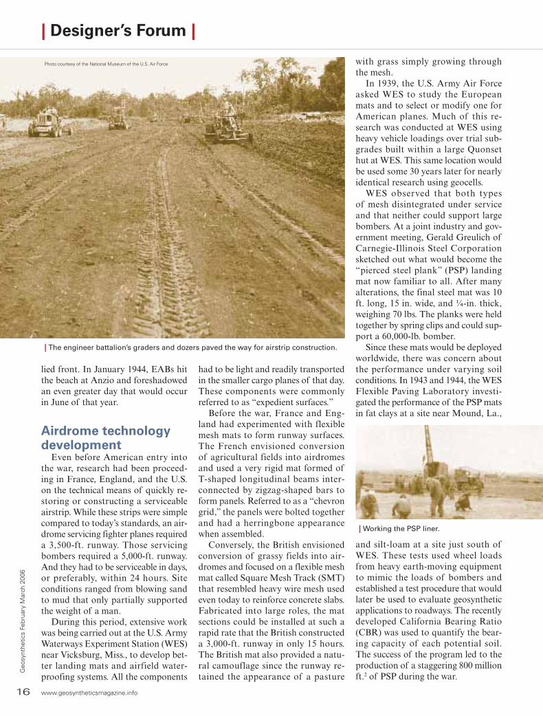
| The engineer battalion’s graders and dozers paved the way for airstrip construction.
lied front. In January 1944, EABs hit the beach at Anzio and foreshadowed an even greater day that would occur in June of that year.
Airdrome technologydevelopment
Even before American entry into the war, research had been proceed-ing in France, England, and the U.S. on the technical means of quickly re-storing or constructing a serviceable airstrip. While these strips were simple compared to today’s standards, an air-drome servicing fighter planes required a 3,500-ft. runway. Those servicing bombers required a 5,000-ft. runway. And they had to be serviceable in days, or preferably, within 24 hours. Site conditions ranged from blowing sand to mud that only partially supported the weight of a man.
During this period, extensive work was being carried out at the U.S. Army Waterways Experiment Station (WES) near Vicksburg, Miss., to develop bet-ter landing mats and airfield water-proofing systems. All the components
had to be light and readily transported in the smaller cargo planes of that day. These components were commonly referred to as “expedient surfaces.”
Before the war, France and Eng-land had experimented with flexible mesh mats to form runway surfaces. The French envisioned conversion of agricultural fields into airdromes and used a very rigid mat formed of T-shaped longitudinal beams inter-connected by zigzag-shaped bars to form panels. Referred to as a “chevron grid,” the panels were bolted together and had a herringbone appearance when assembled.
Conversely, the British envisioned conversion of grassy fields into air-dromes and focused on a flexible mesh mat called Square Mesh Track (SMT) that resembled heavy wire mesh used even today to reinforce concrete slabs. Fabricated into large roles, the mat sections could be installed at such a rapid rate that the British constructed a 3,000-ft. runway in only 15 hours. The British mat also provided a natu-ral camouflage since the runway re-tained the appearance of a pasture
Photo courtesy of the National Museum of the U.S. Air Force
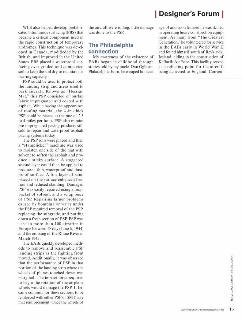
| Working the PSP liner.
and silt-loam at a site just south of WES. These tests used wheel loads from heavy earth-moving equipment to mimic the loads of bombers and established a test procedure that would later be used to evaluate geosynthetic applications to roadways. The recently developed California Bearing Ratio (CBR) was used to quantify the bear-ing capacity of each potential soil. The success of the program led to the production of a staggering 800 million ft.2 of PSP during the war.
www.geosyntheticsmagazine.info 17
Geosynthetics February M
arch 2006
| Designer’s Forum |
WES also helped develop prefabri-cated bituminous surfacing (PBS) that became a critical component used in the rapid construction of temporary airdromes. This technique was devel-oped in Canada, modifieded by the British, and improved in the United States. PBS placed a waterproof sur-facing over graded and compacted soil to keep the soil dry to maintain its bearing capacity.
PSP could be used to protect both the landing strip and areas used to park aircraft. Known as “Hessian Mat,” this PSP consisted of burlap fabric impregnated and coated with asphalt. While having the appearance of roofing material, the ¼-in.-thick PSP could be placed at the rate of 2.5 to 4 miles per hour. PSP also mimics pre-impregnated paving products still sold to repair and waterproof asphalt paving systems today.
The PSP rolls were placed and then a “stamplicker” machine was used to moisten one side of the mat with solvent to soften the asphalt and pro-duce a sticky surface. A staggered second layer could then be applied to produce a thin, waterproof and dust-proof surface. A fine layer of sand placed on the surface enhanced fric-tion and reduced skidding. Damaged PSP was easily repaired using a mop, bucket of solvent, and a scrap piece of PSP. Repairing larger problems caused by bombing or water under the PSP required removal of the PSP, replacing the subgrade, and putting down a fresh section of PSP. PSP was used in more than 100 airstrips in Europe between D-day (June 6, 1944) and the crossing of the Rhine River in March 1945.
The EABs quickly developed meth-ods to remove and reassemble PSP landing strips as the fighting front moved. Additionally, it was observed that the performance of PSP in that portion of the landing strip where the wheels of planes touched down was marginal. The impact force required to begin the rotation of the airplane wheels would damage the PSP. It be-came common for these sections to be reinforced with either PSP or SMT wire mat reinforcement. Once the wheels of
the aircraft were rolling, little damage was done to the PSP.
The Philadelphiaconnection
My awareness of the existence of EABs began in childhood through stories told by my uncle, Dan Ogborn. Philadelphia-born, he escaped home at
age 14 and soon learned he was skilled in operating heavy construction equip-ment. As many from “The Greatest Generation,” he volunteered for service in the EABs early in World War II and found himself south of Reykjavik, Iceland, aiding in the construction of Keflavik Air Base. This facility served as a refueling point for the aircraft being delivered to England. Conven-
18 www.geosyntheticsmagazine.info
Geo
synt
hetic
s Fe
brua
ry M
arch
200
6
| Designer’s Forum |
tional in construction, with concrete runways, this base was placed in ser-vice in March of 1943 and remains in service today.
Later that year, he was transferred to the 834th EAB stationed in Matching Green outside of Essex, England. The 834th was constructing a full-size heavy bomber base that included concrete runways, and an experienced dozer op-erator was in demand. Home was a tent but the wet weather of England
was better than the cold of Iceland. For Uncle Dan, ice was swapped for mud.
In addition to construction of the airfield, the 834th was being prepared for service on the continent. Courses in clearing minefields and training in concealment, chemical warfare, and other tactics were attended with inter-est because on Dec. 23, 1943, the men of the 834th were told that they would participate in a “strategic mission.” Most of the battalion was moved to
Chiseldon Camp, Wiltshire, for train-ing in construction of emergency land-ing strips and ALGs.
Battalion members also began experimenting with waterproofing equipment so that they could operate fully submerged––a hint of what was to come. As fate would have it, my uncle remained in Matching Green completing work on that airstrip. Being new to the battalion, but more-experienced in field construction, he was selected to stay and finish “a few minor details.” In the latter phase of training, the battalion was moved to Torquay, Devonshire, and participated in amphibious landing practice. Uncle Dan remained at Matching Green doing the finishing work.
The 834th returned briefly to Match-ing Green but by April 1, 1944, had moved to Great Barrington, Glouces-tershire, and on April 3 was alerted for a “short sea voyage.” Operation Overlord had begun and D-day was fast approaching. For the next two months the battalion prepared equip-ment, practiced loadings, and made ready. The 834th was divided into seven “serials” that would depart from different locations at different times. At this time they were effectively cut off from the outside world. Uncle Dan remained at Matching Green doing finish work.
A short sea voyageEarly in June 1944, Uncle Dan be-
came a replacement bulldozer operator for an echelon of the 834th designated A-1. Along with echelons A-2 and A-3, they were headed for a landing on
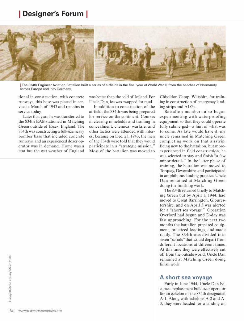
| The 834th Engineer Aviation Battalion built a series of airfields in the final year of World War II, from the beaches of Normandy across Europe and into Germany.

www.geosyntheticsmagazine.info 19
Geosynthetics February M
arch 2006
Omaha Beach at H+4 (4 hours after the initial landing). The short sea jour-ney began on June 3, with equipment and operators loaded in landing-ship tanks (LSTs) for transport across the English Channel.
Each piece of equipment had three operators, with the senior man se-lected to operate the equipment upon landing. Uncle Dan was senior on his dozer. The 24-hour delay of D-day was spent in the LST in the churn-ing channel. On June 6, D-day com-menced and personnel on the LSTs were transferred to a “Rhino Ferry” for transport to the beach. Equipment with operators remained on the LST. That day the Rhino Ferry was unable to reach the beach because of heavy enemy artillery fire. The men spent another night at sea in the LST.
On D+1 (June 7), while still under heavy enemy fire and with minefields uncleared, echelon A-1 finally reached Omaha Beach. Many LSTs could not reach the shoreline because of steel pilings driven in the shallows intended to rip out the bottoms of approach-ing vessels. However, the equipment had been waterproofed to operate completely submerged, though the operators still needed air.
That day, Uncle Dan had his first and last opportunity to drive a fully submerged bulldozer on a beach ap-proach. The ability of a dozer blade to repel machine gun fire was quickly appreciated by Uncle Dan. The sight of a large dozer coming ashore must have been confusing at best. Once on the beach, the operator had to quickly remove all of the now unneeded wa-terproofing. The 834th EAB had ar-rived in France.
ELS-1 at St.Pierre-du-Mont/St.Laurent-sur-Mer
The ground troops that now poured up the beaches needed air cover to protect them from continued enemy fire. The 819th EAB at Utah Beach had managed to establish an ELS airstrip on D-day that allowed spotter planes to land. The 834th landed on D+1 and found their in-
20 www.geosyntheticsmagazine.info
Geo
synt
hetic
s Fe
brua
ry M
arch
200
6
tended ELS site still in enemy hands. Lt. Col. John Livingston of the 834th requested permission to seek an alternate site and one was located between the villages of St.Pierre-du-Mont and St.Laurent-sur-Mer. The site was on the bluffs overlooking Omaha Beach (see artistic rendering on page 14).
By June 8 (D+2), the strip was op-erational as an ELS for small planes. In 24 hours it had been upgraded to handle C-47 transport planes. As an ELS it consisted simply of a graded and unsurfaced runway. By June 14 (D+8) it had been upgraded to Ad-vanced Landing Ground (ALG), with a PSP/mat-surfaced runway. An aver-age of 100 C-47s landed there daily during the next six weeks. In addition, P-30 and P-47 fighter planes oper-ated from the field as early as June 11, 1944.
With the air superiority of the Al-lies quickly established, the landing strip at St.Pierre-du-Mont/St.Laurent-sur-Mer was again upgraded for bomber support. This required exten-sion of the runway to 5,000 ft., plus the construction of support facilities and bomber parking areas. This site quickly returned to agricultural fields after the war.
Beyond D-dayAs the war advanced in Europe, the
capture of enemy airfields that were readily repaired reduced the need for ELS strips and more attention was paid to the repair of damaged con-ventional runways. Uncle Dan shipped home before the May 8, 1945 capitu-lation of Germany. Assigned to the Ordinance Arsenal in eastern Oregon, he met my aunt and became a part of my life.
The facility at WES that had served so well in evaluating landing mats for airplanes would return to service in the later 1970s and early ‘80s to evaluate geosynthetic alternatives for roadways and runways. Fabric im-pregnated with asphalt would provide a poor landing surface for today’s jet fighters but continues to serve a role in paving overlay applications.
On the worst days of my career, I have always thought of Uncle Dan driving a submerged bulldozer onto Omaha Beach.
Compared to that, mine has been an easy job.
References“Thus We Served: A History of the 834th
Engineering Aviation Battalion”“U.S. Army Air Forces Continental Airfields:
D-Day to V-E Day” Research Division, USAF Historical Research Center, Max-well Air Force Base, Alabama, 1988
“Landing Mat Development at WES” by Michael C. Robinson, in U.S. Army Engineers in World War II, U.S. Corps of Engineers, December 18, 1992.
Chapter 9, The Aviation Engineers in Af-rica and Europe, from ”The Army Air Force in World War II” edited by W.F. Craven and J.L. Cate
| Designer’s Forum |
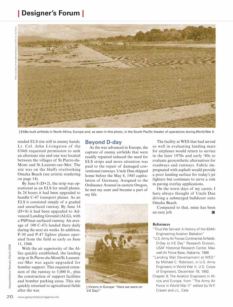
| EABs built airfields in North Africa, Europe and, as seen in this photo, in the South Pacific theater of operations during World War II.
Pho
to c
ourt
esy
of t
he N
atio
nal M
useu
m o
f th
e U
.S. A
ir Fo
rce
| Victory in Europe: “Here we were onV-E Day!”
Project Showcase| Rejunevation construction at a regional airport in Missouri and baffle-curtain usage at a paper mill in Mississippi showcase geosynthetics in action.
| E.Lyn Heying, P.G., of MECO Engineering Co. contributed to this article.
22 www.geosyntheticsmagazine.info
Geo
synt
hetic
s Fe
brua
ry M
arch
200
6
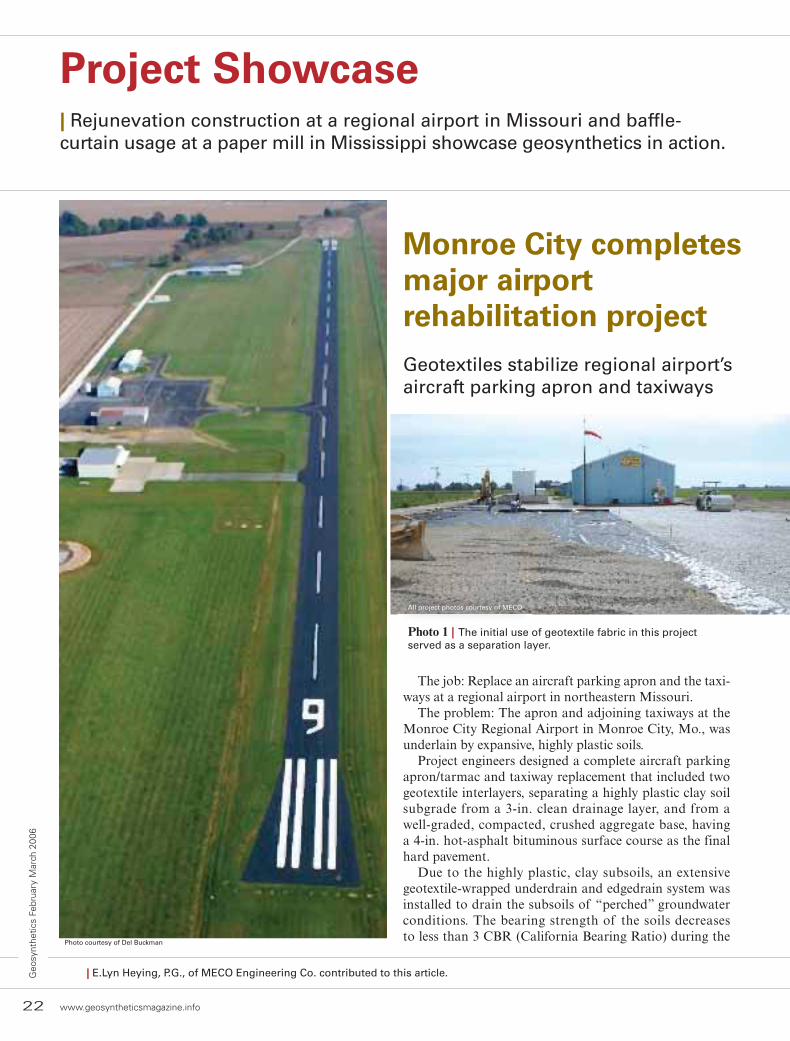
Monroe City completes major airportrehabilitation projectGeotextiles stabilize regional airport’saircraft parking apron and taxiways
The job: Replace an aircraft parking apron and the taxi-ways at a regional airport in northeastern Missouri.
The problem: The apron and adjoining taxiways at the Monroe City Regional Airport in Monroe City, Mo., was underlain by expansive, highly plastic soils.
Project engineers designed a complete aircraft parking apron/tarmac and taxiway replacement that included two geotextile interlayers, separating a highly plastic clay soil subgrade from a 3-in. clean drainage layer, and from a well-graded, compacted, crushed aggregate base, having a 4-in. hot-asphalt bituminous surface course as the final hard pavement.
Due to the highly plastic, clay subsoils, an extensive geotextile-wrapped underdrain and edgedrain system was installed to drain the subsoils of “perched” groundwater conditions. The bearing strength of the soils decreases to less than 3 CBR (California Bearing Ratio) during the
Photo courtesy of Del Buckman
All project photos courtesy of MECO
Photo 1 | The initial use of geotextile fabric in this project served as a separation layer.

www.geosyntheticsmagazine.info 23
Geosynthetics February M
arch 2006
spring months of March and April, thus requiring the geotextile solution.
Geotextile fabrics and high-density polyethylene (HDPE) drainage systems also helped create an innovative design to stabilize the aircraft parking apron pavement geometry.
In autumn of 2005, major improvements to the Monroe City Regional Airport were completed through the Federal Aviation Administration Airport, Capital Improvement Program, administered through the Missouri Department of Transpor-tation (MoDOT), Aviation Divi-sion. MECO Engineering Co. Inc. of Hannibal, Mo. provided the design engineering and construc-tion administration services for this project, emphasizing the use of geo-synthetic textiles.
Phase I of this project began in the fall of 2004 with the sealing and striping of the runway and taxiway. Phase II began with the removal of the apron and taxiways in the sum-mer of 2005. Placement of the geo-textile fabrics, a new pavement sur-face, and final construction activities were completed in the fall of 2005.
Before the geotextile separation fabric could be placed between the plastic soil subgrade, the existing apron and taxiway pavement foundation materials had to be removed. The excavated materials, including existing aggregate base and underlying subsoils, were transported to the aircraft protection zone at the east end of runway 9-27. Once in place, the soils were compacted by the Monroe City Street Department.
Airport improvements included removal and replacement of approximately 8,520 yd.2 of aircraft parking apron pave-ment; installation of 20,650 yd.2 of two separate layers of Propex 2006 woven geotextile separation and reinforcement fabric; installation of 1,048 ft. of pavement underdrain and edgedrain system; aircraft parking apron placement of ap-proximately 2,500 tons of hot-mix asphalt; aircraft tiedown
locations; Advanced Drainage System HDPE stormwater drainage piping, site grading, seeding, mulching; and con-struction of a 24-in., flat-bottom drainage ditch around the perimeter of the aircraft parking apron.
The woven geotextile fabric was used in a mattress design method, with a top and bottom layer. After all existing pavement materials were removed and the soil subgrade pre-pared, the first layer of woven geotextile fabric was placed
and overlapped on top of the soil subgrade. The first layer of geotextile fabric (Photo 1) served as a separation layer between natural highly plastic clay (CH) soils and a 6-in.-thick crushed stone aggregate drainage layer. The drainage layer was composed of 3-in. clean aggregate limestone.
Once the drainage layer was in place, and point-to-point contact was achieved, the second (top) layer of woven geotextile (Photos 2 & 3) was placed and over-lapped. The second layer of geotextile served as a separa-tion and reinforcement layer
between the open-graded drainage layer and the 6-in., compacted MoDOT Type 5 Aggregate Base (Photos 4 & 5). When specified base density was achieved, new 4-in.-thick asphalt aircraft parking apron and taxiways pavement mat were placed and compacted.
Previous improvements to the airport facilities in Monroe City include the replacement of runway 9-27 in 1998. Proj-ect components for that project required soil stabilization, full-depth, hot-mix asphalt runway surface, underdrain system, and runway lighting. MECO Engineering also as-sisted Monroe City officials in obtaining federal support for these projects, ensuring the continuation of operations at this facility that is central to the continued economic growth of the community and the region.
Photos 2 & 3 | A second layer of woven geotextile was placed and overlapped.
Photos 4 & 5 | The final aggregate layer is appliedand compacted.
24 www.geosyntheticsmagazine.info
Geo
synt
hetic
s Fe
brua
ry M
arch
200
6
Project Showcase
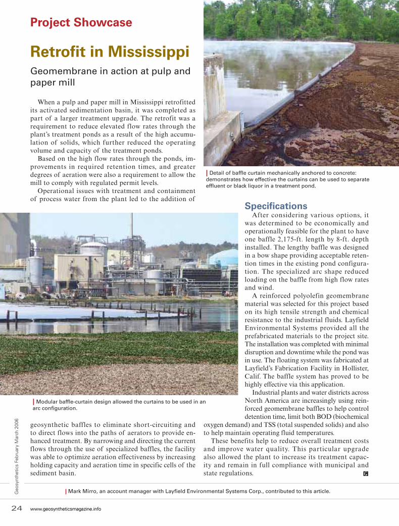
Retrofit in MississippiGeomembrane in action at pulp and paper mill
When a pulp and paper mill in Mississippi retrofitted its activated sedimentation basin, it was completed as part of a larger treatment upgrade. The retrofit was a requirement to reduce elevated flow rates through the plant’s treatment ponds as a result of the high accumu-lation of solids, which further reduced the operating volume and capacity of the treatment ponds.
Based on the high flow rates through the ponds, im-provements in required retention times, and greater degrees of aeration were also a requirement to allow the mill to comply with regulated permit levels.
Operational issues with treatment and containment of process water from the plant led to the addition of
Specifications After considering various options, it
was determined to be economically and operationally feasible for the plant to have one baffle 2,175-ft. length by 8-ft. depth installed. The lengthy baffle was designed in a bow shape providing acceptable reten-tion times in the existing pond configura-tion. The specialized arc shape reduced loading on the baffle from high flow rates and wind.
A reinforced polyolefin geomembrane material was selected for this project based on its high tensile strength and chemical resistance to the industrial fluids. Layfield Environmental Systems provided all the prefabricated materials to the project site. The installation was completed with minimal disruption and downtime while the pond was in use. The floating system was fabricated at Layfield’s Fabrication Facility in Hollister, Calif. The baffle system has proved to be highly effective via this application.
Industrial plants and water districts across North America are increasingly using rein-forced geomembrane baffles to help control detention time, limit both BOD (biochemical
oxygen demand) and TSS (total suspended solids) and also to help maintain operating fluid temperatures.
These benefits help to reduce overall treatment costs and improve water quality. This particular upgrade also allowed the plant to increase its treatment capac-ity and remain in full compliance with municipal andstate regulations.
| Modular baffle-curtain design allowed the curtains to be used in anarc configuration.
| Detail of baffle curtain mechanically anchored to concrete:demonstrates how effective the curtains can be used to separate effluent or black liquor in a treatment pond.
geosynthetic baffles to eliminate short-circuiting and to direct flows into the paths of aerators to provide en-hanced treatment. By narrowing and directing the current flows through the use of specialized baffles, the facility was able to optimize aeration effectiveness by increasing holding capacity and aeration time in specific cells of the sediment basin.
24 www.geosyntheticsmagazine.info
Geo
synt
hetic
s Fe
brua
ry M
arch
200
6
| Mark Mirro, an account manager with Layfield Environmental Systems Corp., contributed to this article.
26 www.geosyntheticsmagazine.info
Geo
synt
hetic
s Fe
brua
ry M
arch
200
6
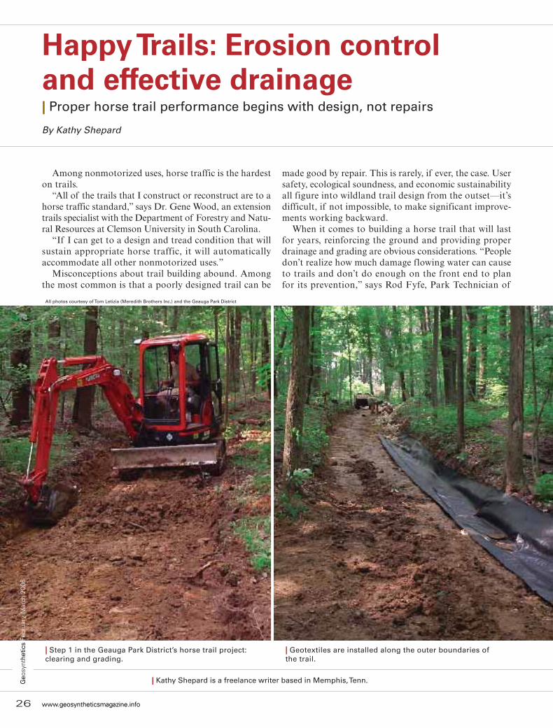
Happy Trails: Erosion controland effective drainage| Proper horse trail performance begins with design, not repairs
By Kathy Shepard
All photos courtesy of Tom Letizia (Meredith Brothers Inc.) and the Geauga Park District
| Step 1 in the Geauga Park District’s horse trail project:clearing and grading.
| Geotextiles are installed along the outer boundaries ofthe trail.
Among nonmotorized uses, horse traffic is the hardest on trails.
“All of the trails that I construct or reconstruct are to a horse traffic standard,” says Dr. Gene Wood, an extension trails specialist with the Department of Forestry and Natu-ral Resources at Clemson University in South Carolina.
“If I can get to a design and tread condition that will sustain appropriate horse traffic, it will automatically accommodate all other nonmotorized uses.”
Misconceptions about trail building abound. Among the most common is that a poorly designed trail can be
made good by repair. This is rarely, if ever, the case. User safety, ecological soundness, and economic sustainability all figure into wildland trail design from the outset—it’s difficult, if not impossible, to make significant improve-ments working backward.
When it comes to building a horse trail that will last for years, reinforcing the ground and providing proper drainage and grading are obvious considerations. “People don’t realize how much damage flowing water can cause to trails and don’t do enough on the front end to plan for its prevention,” says Rod Fyfe, Park Technician of
26 www.geosyntheticsmagazine.info
Geo
synt
hetic
s Fe
brua
ry M
arch
200
6
| Kathy Shepard is a freelance writer based in Memphis, Tenn.

www.geosyntheticsmagazine.info 27
| Rocks to cover the geotextile liners help create thetrail-side drain.
| The installation of 6-in. geocell material directly on the trail will allow the entire trail system to drain properly.
Geauga Park District in Ohio’s Geauga County, who oversaw the recent Presto Geoweb work on the park’s Affelder Trail. He says erosion and standing water cause the most destruction.
Because horse trails often form naturally, planners too often believe that they are self-sustaining. “People see trails when they are new and dry but don’t realize what will happen once the hikers and horses get on it and the water starts affecting it,” says Fyfe. “Geosynthetics are designed to inhibit those problems.”
Site-specific use of geotextilesGeosynthetics can be used wherever maintenance can
be reduced and trail stability increased. Geotextiles rein-force weak spots along the trail. Wood said he uses geo-synthetics for bank stabilization (Pyramat), tread hard-ening, bog and low-water crossings, and French drain construction, as well as for tieing stations at trailheads and campgrounds. The use of geotextiles is especially important on trails where there are mudholes, seeps, bogs, and low-water crossings. The problem presented by mudholes, where drainage is impaired, can be solved by excavating the soft mud to a firm surface in the soil
profile. Wood recommends first lining the hole with a 5-oz., nonwoven geotextile, then filling the lined cavity with crush-and-run gravel to a high enough level that surface water will be diverted from the trail.
On trails not affected by soil moisture, geosynthetics will be most useful for switchbacks and excavated bank approaches to stream-level crossings where the stonesaccount for less than about 40% of the surface soil volume.
“If there is an abundance of natural flat stones on the soil surface near the work site, the tread can be hardened using those materials,” Wood explained. “However, as the stoniness declines, these treads increasingly need to be hardened using geosynthetics.”
In the case of switchbacks, Wood has seen how horse and hiker traffic tend to cut the inside of the turn and eventually wear a groove or rut that collects surface water flow. “As the groove progresses to a rut, without mitiga-tion, it eventually develops into a gully. In the process of construction or reconstruction, the upper leg of the switchback should be smoothed and insloped.”
Another water threat is seeps, natural phenomena that occur on soils with a high clay component or where the soil is shallow and water runs across the surface of bedrock and onto the trail tread. Vertical drainage
Geosynthetics February M
arch 2006

28 www.geosyntheticsmagazine.info
Geo
synt
hetic
s Fe
brua
ry M
arch
200
6
Happy Trails
below the soil pan (also called hard- pan) is impaired at best or prevented at worst. As soil water accumulates, an anaerobic condition develops and trail traffic turns the site muddy, even during droughts.
Low-water crossings must beapproached with sensitivity to state and federal regulations. Any distur-bance to the channel of a perennial stream will require, at the very least, a permit issued by the Army Corps of Engineers or a state agency.
When the trail crosses a stream, the hardness of the streambed will dictate whether and what type of reinforce-ment is used. If hard sand composes the bed, reinforcement can help prevent the potential damage from trail riders. As the streambed becomes softer, the need for hardening with combinations of geotextile, geogrid, and geoweb be-comes increasingly important. Once the bottom reaches a moderately soft condition, the trail builder should con-sider reinforcing the geotextile with a layer of geogrid before the geoweb is put into place. Curbing timbers should be placed on both the upstream and downstream sides of the geocellular system. Timbers should be anchored in place with 3/4-in. rebar driven at least 5 ft. into the ground or bedrock, whichever comes first. The anchoring rebar should be angled with the bars pointing upstream. Filling the geocells with crush-and-run gravel creates the tread surface.
Horse trailsThe special needs of horse trail
construction make them more dif-ficult to construct and permit. Fyfe said that horses present a special challenge to the engineer for two reasons: the heavy combined weight of the horse and rider, and the con-centration of the weight (upwards of 1500 lbs) on a very small surface area (four hooves). “Horse trails are a little more difficult [to construct and permit] because of the point load-ing, and they have to be wider,” he explained. “Building a lasting horse trail requires reinforcing the ground, providing proper grading and drain-
| The trail is completed when infilled with cover aggregate and appropriately spaced water-bar timbers.

www.geosyntheticsmagazine.info 29
Geosynthetics February M
arch 2006
age. Geosynthetics help inhibit the standing water problems attendant on the heavy weight of horses.”
Trail trendsThe Transportation Equity Act,
administered by the Federal High-way Administration’s Recreational Trails Program, gives approximately $60 million per year to the individual states for grant-proposed trail project funding (U.S. Department of Trans-portation Federal Highway Admin-istration Web site). The Act specifies that 30% of the funds are to be al-located for motorized trail projects, 40% for shared-use trails, and 30% for single-use, nonmotorized trails.
More trails completed recently,such as the ones created by the Geauga Park District, fit the needs of an aging population, which includes tailoring the trails to Americans with Disabili-ties Act specifications. “We are puttingin more ‘rails to trails’ projects asthe baby boomers are getting older,” says Fyfe.
SourcesGene Wood, Professor and Exten-
sion Trails Specialist, Department ofForestry and Natural Resources,Clemson University, Clemson, S.C.,+1 864 656 0319
Rod Fyfe, Park Technician, Geauga Park District, Chardon, Ohio, +1 440 564 9449 (via Tom Letizia, Technical Sales Manager, Meredith Brothers, Inc., Cleveland, Ohio, +1 440 668 1772 or +1 444 543 7973)
Editor’s note:In mid-to-late 2006, the United
States Department of Agriculture (USDA) Forest Service will publish a new book about horse trail con-struction and maintenance issues. The publication will focus on ecologi-cally sound design and will include a substantial discussion on the use of geosynthetic materials. Funding will be provided by the Federal Highway Administration’s (FHWA) Recreational Trails Program. For more about this program, visit the Web site: www.fhwa.dot.gov/environment/rectrails
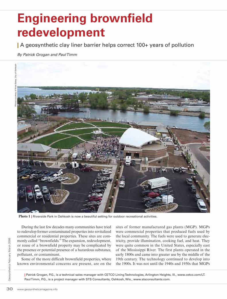
Engineering brownfieldredevelopment| A geosynthetic clay liner barrier helps correct 100+ years of pollution
By Patrick Grogan and Paul Timm
During the last few decades many communities have tried to redevelop former contaminated properties into revitalized commercial or residential properties. These sites are com-monly called “brownfields.” The expansion, redevelopment, or reuse of a brownfield property may be complicated by the presence or potential presence of a hazardous substance, pollutant, or contaminant.
Some of the more difficult brownfield properties, where known environmental concerns are present, are on the
sites of former manufactured gas plants (MGP). MGPs were commercial properties that produced fuels used by the local community. The fuels were used to generate elec-tricity, provide illumination, cooking fuel, and heat. They were quite common in the United States, especially east of the Mississippi River. The first plants operated in the early 1800s and came into greater use by the middle of the 19th century. The technology continued to develop into the 1900s. It was not until the 1940s and 1950s that MGPs
30 www.geosyntheticsmagazine.info
Geo
synt
hetic
s Fe
brua
ry M
arch
200
6
| Patrick Grogan, P.G., is a technical sales manager with CETCO Lining Technologies, Arlington Heights, Ill., www.cetco.com/LT.
Paul Timm, P.G., is a project manager with STS Consultants, Oshkosh, Wis., www.stsconsultants.com.
Photo 1 | Riverside Park in Oshkosh is now a beautiful setting for outdoor recreational activities.
Ph
oto
s co
urt
esy
of
Kri
sti B
ales
, Cit
y o
f O
shko
sh

www.geosyntheticsmagazine.info 31
Geosynthetics February M
arch 2006saw their end as natural gas was found to be a more economical choice for a variety of residential, municipal, and commercial uses.
It is estimated that there were about 3,500 significant MGP sites in the United States.
The problemswith coal tarThe MGP manufacturing process involved heating various organic materials such as coke or coal to produce a gas. The gas product, often called “manufactured gas” or “town gas,” was filtered, stored and then distributed for residential, municipal, and commercial use. As a result of this process, a tar-like substance was produced. The tar-like by-product
(“coal tar”) was often disposed of somewhere on the manufacturing facility’s property.
Several decades ago it became ap-parent that these by-products posed an environmental and human health concern. The primary contaminants of concern are compounds called polycyclic aromatic hydrocarbons (PAH) and metals, and they are common finds at former MGP sites. The compounds are difficult to clean up and they are very resistant to natural degradation. Quite often when the coal tar is discovered, the product looks as though it has not changed since it was deposited many years ago.
Also, compounds cling to the soil particles to such a point that it is difficult to physically remove the
Photo 2 | Preparing the site for construction and storing materials for later use.
Photo 3 | To compensate for expected root growth, a GCL-lined trench was designed.
Ph
oto
3 c
ou
rtes
y o
f Pa
tric
k G
roga
n
32 www.geosyntheticsmagazine.info
Geo
synt
hetic
s Fe
brua
ry M
arch
200
6
compounds from the soils. As a result, one of the primary methods for remov-ing the contaminated soils is through soil excavation and removal. The con-taminated soils are then disposed of at a facility that is permitted to accept this type of waste or the soil can be thermally treated. Thermal treatment involves burning or roasting the soils to remove or strip out the PAHs and other compounds. The soils are then analyzed for any residual contaminants and then may be used as fill material for additional site use.
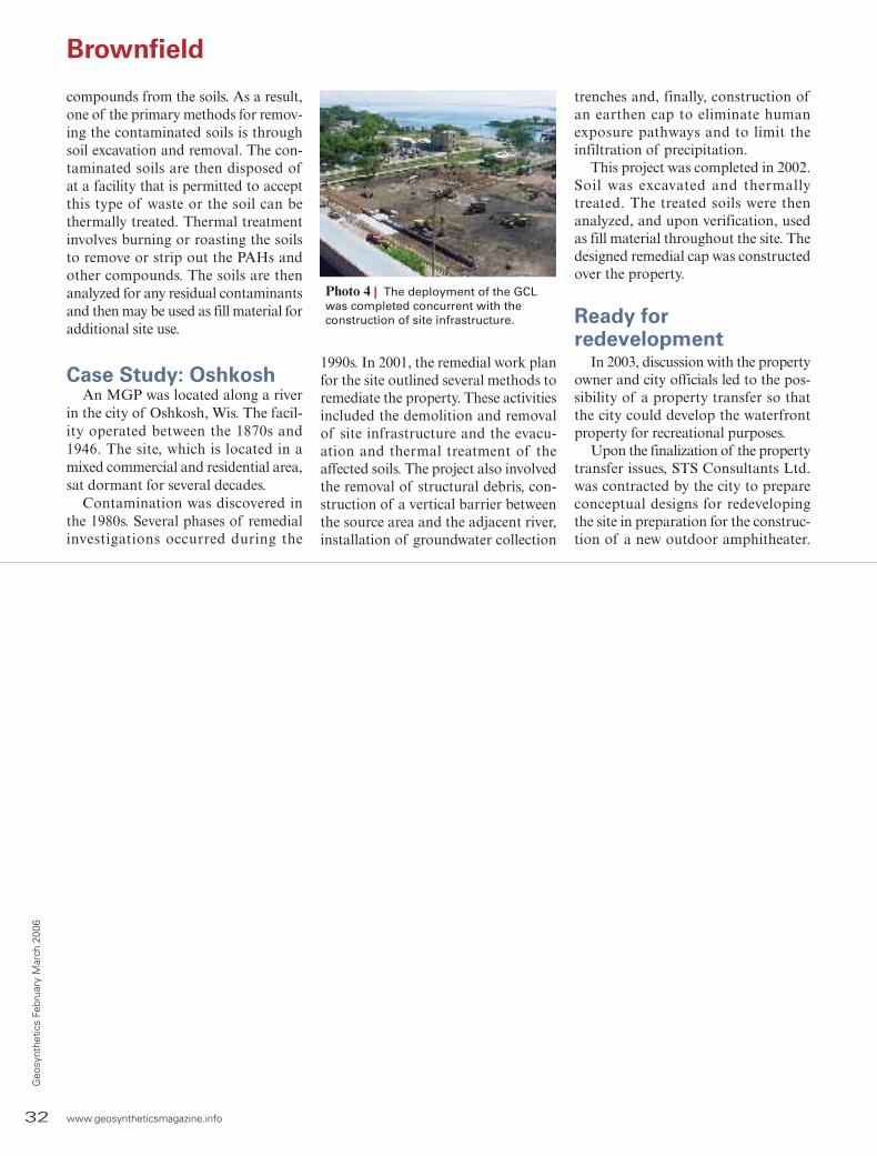
Case Study: OshkoshAn MGP was located along a river
in the city of Oshkosh, Wis. The facil-ity operated between the 1870s and 1946. The site, which is located in a mixed commercial and residential area, sat dormant for several decades.
Contamination was discovered in the 1980s. Several phases of remedial investigations occurred during the
1990s. In 2001, the remedial work plan for the site outlined several methods to remediate the property. These activities included the demolition and removal of site infrastructure and the evacu-ation and thermal treatment of the affected soils. The project also involved the removal of structural debris, con-struction of a vertical barrier between the source area and the adjacent river, installation of groundwater collection
trenches and, finally, construction of an earthen cap to eliminate human exposure pathways and to limit the infiltration of precipitation.
This project was completed in 2002. Soil was excavated and thermally treated. The treated soils were then analyzed, and upon verification, used as fill material throughout the site. The designed remedial cap was constructed over the property.
Ready forredevelopment
In 2003, discussion with the property owner and city officials led to the pos-sibility of a property transfer so that the city could develop the waterfront property for recreational purposes.
Upon the finalization of the property transfer issues, STS Consultants Ltd. was contracted by the city to prepare conceptual designs for redeveloping the site in preparation for the construc-tion of a new outdoor amphitheater.
Brownfield
Photo 4 | The deployment of the GCL was completed concurrent with theconstruction of site infrastructure.

www.geosyntheticsmagazine.info 33
Geosynthetics February M
arch 2006
The project was called the Riverside Park Redevelopment Project. These site preparations included removing the pre-existing environmental cap to pre-pare the site for construction activities and storing the materials for later use (Photo 2). The site was regraded and the cap was replaced.
In some areas, a new environmental cap was constructed using a variety of barrier materials, including concrete or asphalt pavement in areas near the performance pavilion. In the greens-pace and pavement component of the design, a geosynthetic clay liner (GCL) was incorporated as the en-gineered barrier. Bentomat ST GCL manufactured by CETCO Lining Technologies was selected.
The GCL is a reinforced variety consisting of a layer of Volclay so-dium bentonite encapsulated between two geotextiles; needle-punched to-gether for strong performance under a wide variety of field conditions. The integrated matrix of bentonite and
needle-punched fibers provide high sheet strength and allows the GCL to maintain low permeability. The product’s ASTM certified permeabil-ity is 5x10⁻⁹ cm/sec.
The consultant’s innovative design concept was incorporated in areas where trees were going to be planted. To compensate for expected root growth, a GCL-lined trench was de-signed (Photo 3). The tree growth zone was lined with the same type of GCL and backfilled with clean topsoil. A gravity drain tile system was incorpo-rated into the design to intercept excess storm or irrigation water to control the water level in the sealed trench. An ad-vantage with this design was that any root penetration of the GCL would self-heal the puncture. Approximately 120,000 ft.2 of GCL material was used in this project. Deployment took ap-proximately 6 weeks. The deployment of the GCL took place concurrent with the construction of site infrastructure (Photo 4).
Creating a benchmarkThe use of the GCL as an engi-
neered barrier was approved by the Wisconsin Department of Natural Resources (DNR). The Riverside Park Project is one of the first signifi-cant uses of a GCL as an engineered barrier in the state. Since completion in autumn 2004, the site has been used for various recreational activities and public events, such as outdoor music performances (Photo 1, page 30).
This project has illustrated how creativity, cooperation, and foresight have fulfilled many of the goals of a brownfield redevelopment. Although the site owner was faced with the many challenges associated with MGP site remediation, the cooperation and vision of the city, the consultants, and the DNR led to an increased ac-cessibility between residents and the riverfront. It’s given the community something it hasn’t had in more than 100 years: a safe, clean shoreline.
Brownfield

The formation of ochre biofilmin geotextile filters| A closer look at drainage performance at the interface of aeratedand non-aerated environmentsBy Marcos Barreto Mendonça, Mauricio Ehrlich, and Magali Christe Cammarota
Several cases have been recorded in the literature that describe the occurrence of ochre biofilm for-mation in pipes used in water sup-ply systems, sand drains in earth dams, water collection wells, deep horizontal drains, and drainage sys-tems using geotextiles. Ochre is a substance rich in iron oxides and organic matter, and it may form in drainage systems after a period of time. It adheres to the solid surfaces of such systems and may cause clog-ging, as it reduces the void spaces available in the drain for water per-colation. This may have undesirable implications: a decrease in the drain-age flow capacity and an increase in soil pore pressure; instability of soil masses and retaining systems; or an alteration of the flow direction and development of piping.
Ochre formation results from mi-crobial colonization by bacterial consortia (biofilm) that may include various iron bacteria and its affinity to iron compounds. Specific envi-ronmental parameters, namely the composition of the draining fluid, pH, electrochemical potential, and aeration, are associated with different interactions be-tween the chemical substances and the microorganisms, resulting in varied types of ochre formation and rates at which the ochre forms. See References: Further details on this phenomenon are found in Mendonça (2000) and Mendonça et al. (2003).
Even though geotextiles have been used extensivelyin drainage systems, very few studies have beenreported on ochre formation and its effects on their long-term performance.
The purpose of this presentation is to study how the phenomenon occurs in drainage systems using geotextile filters and to better understand the microbial activity in-
34 www.geosyntheticsmagazine.info
Geo
synt
hetic
s Fe
brua
ry M
arch
200
6
| Marcos Barreto Mendonça works for Terrae Engenharia Geotécnica Ltda.
Mauricio Ehrlich and Magali Christe Cammarota work for Federal University of Rio de Janeiro, Brazil.
Soil
Water + dissolved iron
Iron solubilization
Filter Drain
Iron oxidation/precipitation
Geochemical evolution:
• Fe• Organo-iron complex
+2 Fe Fe O+32 3
Chemical reactions + microbial activity
volved. The experiments were performed in a laboratory using column filter tests on three kinds of geotextile.
Ochre biogeochemistryIron may be found either dissolved or precipitated, de-
pending on the electrochemical conditions of the medium (the pH and the partial oxygen pressure). The iron can mi-grate together with groundwater when it is dissolved. Iron is normally dissolved in one of two ways: either as an Fe+2 ion (reduced iron) or in an organic-metallic complex. In an organic-metallic complex, the organic part is associated to the Fe+2 or Fe+3 ions, and keeps them dissolved even when conditions are favorable for their precipitation.
Figure 1 | The geochemical processes that affect iron and which may be responsible for the formation of ochre clogging in drainage systems.
www.geosyntheticsmagazine.info 35
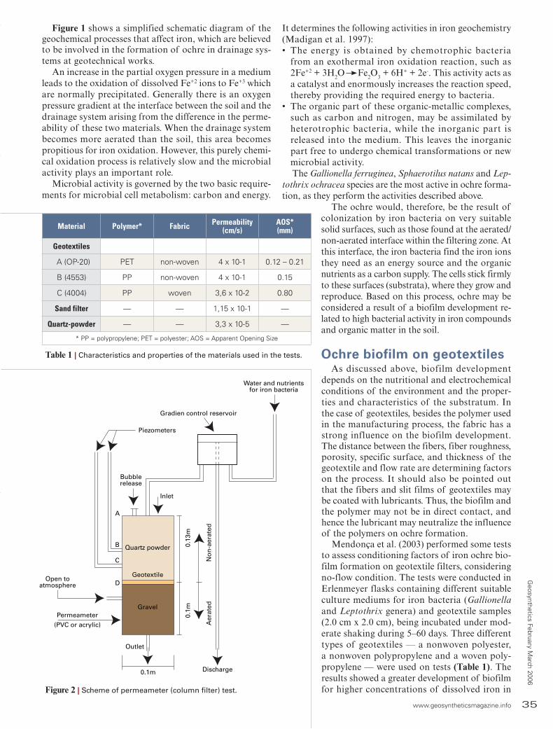
Table 1 | Characteristics and properties of the materials used in the tests.
It determines the following activities in iron geochemistry (Madigan et al. 1997):• The energy is obtained by chemotrophic bacteria
from an exothermal iron oxidation reaction, such as2Fe+2 + 3H2O Fe2O3 + 6H+ + 2e-. This activity acts as a catalyst and enormously increases the reaction speed, thereby providing the required energy to bacteria.
• The organic part of these organic-metallic complexes, such as carbon and nitrogen, may be assimilated by heterotrophic bacteria, while the inorganic part is released into the medium. This leaves the inorganic part free to undergo chemical transformations or new microbial activity.The Gallionella ferruginea, Sphaerotilus natans and Lep-
tothrix ochracea species are the most active in ochre forma-tion, as they perform the activities described above.
The ochre would, therefore, be the result of colonization by iron bacteria on very suitable solid surfaces, such as those found at the aerated/non-aerated interface within the filtering zone. At this interface, the iron bacteria find the iron ions they need as an energy source and the organic nutrients as a carbon supply. The cells stick firmly to these surfaces (substrata), where they grow and reproduce. Based on this process, ochre may be considered a result of a biofilm development re-lated to high bacterial activity in iron compounds and organic matter in the soil.
Ochre biofilm on geotextilesAs discussed above, biofilm development
depends on the nutritional and electrochemical conditions of the environment and the proper-ties and characteristics of the substratum. In the case of geotextiles, besides the polymer used in the manufacturing process, the fabric has a strong influence on the biofilm development. The distance between the fibers, fiber roughness, porosity, specific surface, and thickness of the geotextile and flow rate are determining factors on the process. It should also be pointed out that the fibers and slit films of geotextiles may be coated with lubricants. Thus, the biofilm and the polymer may not be in direct contact, and hence the lubricant may neutralize the influence of the polymers on ochre formation.
Mendonça et al. (2003) performed some tests to assess conditioning factors of iron ochre bio-film formation on geotextile filters, considering no-flow condition. The tests were conducted in Erlenmeyer flasks containing different suitable culture mediums for iron bacteria (Gallionella and Leptothrix genera) and geotextile samples (2.0 cm x 2.0 cm), being incubated under mod-erate shaking during 5–60 days. Three different types of geotextiles — a nonwoven polyester, a nonwoven polypropylene and a woven poly-propylene — were used on tests (Table 1). The results showed a greater development of biofilm for higher concentrations of dissolved iron in
Water and nutrientsfor iron bacteria
Gradien control reservoir
Piezometers
Discharge
Aer
ated
N
on
-aer
ated
0.1m
0.1
3m
Quartz powder
Geotextile
Gravel
Inlet
Bubblerelease
Open toatmosphere
Permeameter
(PVC or acrylic)
A
B
C
D
Outlet
0.1m
Figure 2 | Scheme of permeameter (column filter) test.
Material Polymer* Fabric Permeability(cm/s)
AOS*(mm)
Geotextiles
A (OP-20) PET non-woven 4 x 10⁻¹ 0.12 – 0.21
B (4553) PP non-woven 4 x 10⁻¹ 0.15
C (4004) PP woven 3,6 x 10⁻² 0.80
Sand filter — — 1,15 x 10⁻¹ —
Quartz-powder — — 3,3 x 10⁻⁵ —
* PP = polypropylene; PET = polyester; AOS = Apparent Opening Size
Figure 1 shows a simplified schematic diagram of the geochemical processes that affect iron, which are believed to be involved in the formation of ochre in drainage sys-tems at geotechnical works.
An increase in the partial oxygen pressure in a medium leads to the oxidation of dissolved Fe+2 ions to Fe+3 which are normally precipitated. Generally there is an oxygen pressure gradient at the interface between the soil and the drainage system arising from the difference in the perme-ability of these two materials. When the drainage system becomes more aerated than the soil, this area becomes propitious for iron oxidation. However, this purely chemi-cal oxidation process is relatively slow and the microbial activity plays an important role.
Microbial activity is governed by the two basic require-ments for microbial cell metabolism: carbon and energy.
Geosynthetics February M
arch 2006

36 www.geosyntheticsmagazine.info
Geo
synt
hetic
s Fe
brua
ry M
arch
200
6
the culture medium and for larger amounts of available dissolved oxy-gen in the water, until a certain maxi-mum level because too much oxygen has shown a detrimental action. pH values greater than 5.0 do not have a considerable influence on biofilm formation. Low bacterial activity and ochre formation was verified for pH 3.3 because low pH is inhibitory to Gallionella and Leptothrix.
Ochre formation depended on the type of geotextile used. Nevertheless, the difference of geotextile polymer may not represent an important role in ochre formation. Ochre formation varied over time and showed a higher initial rate in the nonwoven geotextiles. The tests on the woven polypropylene geotextile showed the smallest accu-mulation of ochre and the tests on the nonwoven polypropylene the greatest, almost double the value observed in the other geotextiles. The fact that the fibers in the nonwoven geotextile have Figure 3 | Visual aspects of the materials in the column filters after the tests.
Inlet
Upstream surface of thegeotextile (in contact with
the quartz powder) totally clean
Gravel heavilycontaminated by orange
substances, reducing as itgets further from geotextile
Outlet
White-colouredquartz powder
Grey patcheson the walls
Surface in contactwith the gravel
contaminated byorange substances
Ochre biofilm

www.geosyntheticsmagazine.info 37
Geosynthetics February M
arch 2006
a much larger specific surface area than in the woven geotextile may be responsible for this difference of be-havior. The authors pointed out that in spite of the higher biofilm formation verified in the nonwoven geotextile, this does not mean that this type of geotex-tile may have a higher potential for clogging. The concentrated openings
of the woven geotextile could lead to this type of geotextile a more favor-able condition for clogging.
Column testsColumn tests were set up to simu-
late the percolation process under optimum ochre formation conditions
and to check its effect on the perme-ability of the drainage system. The tests were undertaken at the Labo-ratory of Geotechnics of COPPE/UFRJ, with the support of the School of Chemistry of UFRJ (Federal Uni-versity of Rio de Janeiro).
The test basically consisted of making a fluid composed of water,
Ochre biofilm
Photo 1 | Visual aspects of the geotextile face in contact to the gravel (contaminated by ochre). From left to right: geotextilesA, B and C.
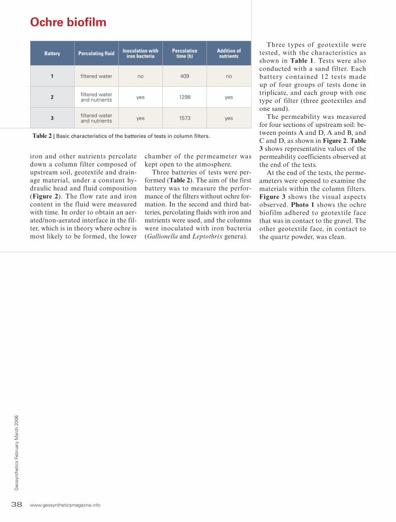
38 www.geosyntheticsmagazine.info
Geo
synt
hetic
s Fe
brua
ry M
arch
200
6
iron and other nutrients percolate down a column filter composed of upstream soil, geotextile and drain-age material, under a constant hy-draulic head and fluid composition (Figure 2). The flow rate and iron content in the fluid were measured with time. In order to obtain an aer-ated/non-aerated interface in the fil-ter, which is in theory where ochre is most likely to be formed, the lower
chamber of the permeameter was kept open to the atmosphere.
Three batteries of tests were per-formed (Table 2). The aim of the first battery was to measure the perfor-mance of the filters without ochre for-mation. In the second and third bat-teries, percolating fluids with iron and nutrients were used, and the columns were inoculated with iron bacteria (Gallionella and Leptothrix genera).
Three types of geotextile were tested, with the characteristics as shown in Table 1. Tests were also conducted with a sand filter. Each battery contained 12 tests madeup of four groups of tests done in triplicate, and each group with one type of filter (three geotextiles and one sand).
The permeability was measured for four sections of upstream soil: be-tween points A and D, A and B, and C and D, as shown in Figure 2. Table 3 shows representative values of the permeability coefficients observed at the end of the tests.
At the end of the tests, the perme-ameters were opened to examine the materials within the column filters. Figure 3 shows the visual aspects observed. Photo 1 shows the ochre biofilm adhered to geotextile face that was in contact to the gravel. The other geotextile face, in contact to the quartz powder, was clean.
Ochre biofilm
Table 2 | Basic characteristics of the batteries of tests in column filters.
Battery Percolating fluid Inoculation with iron bacteria
Percolationtime (h)
Addition ofnutrients
1 filtered water no 409 no
2 filtered waterand nutrients yes 1298 yes
3 filtered waterand nutrients yes 1573 yes

www.geosyntheticsmagazine.info 39
Geosynthetics February M
arch 2006
Ochre biofilm
Table 3 | Permeability values at the end of the tests.
Filter kAD(x 10-5 cm/s)
kAB(x 10-5 cm/s)
KCD(x 10-5 cm/s)
Batteries Batteries Batteries
1 2 3 1 2 3 1 2 3
A 3.0 1.8 2.0 3.0 1.0 3.0 2.5 4.0 2.0
B 5.0 2.0 2.5 5.0 1.0 2.0 6.0 5.0 4.0
C 5.0 2.0 2.0 7.0 1.0 2.0 4.0 3.0 1.8
Sand 7.0 2.5 2.5 5.0 1.8 2.0 — 3.0 2.3

40 www.geosyntheticsmagazine.info
Geo
synt
hetic
s Fe
brua
ry M
arch
200
6
Ochre biofilm
Photo 2 | Microphotographs of geo-textiles samples taken after the end of the tests (batteries 1 and 2) by scanning electron microscopy.
The total iron content (Fe+2 + Fe+3) in the quartz powder from the upper, middle and lower sections of the sand filter was measured after the tests in each battery (Table 4). The aim was to ascertain whether any iron had been precipitated within the column filter.
Microbiological tests identified the presence of iron bacteria of the Gal-lionella and Leptothrix genera in the orange-colored material collected in the lower chamber.
By the visual aspects, as well as the results of the tests of iron content and the microbiological identification, the orange substance found in the filter and the drainage material can be iden-tified as ochre.
Observations were made using scanning electron microscopy in order to analyze the state of the geotex-tile structures after the tests. Photo 2 shows the microphotographs taken after the end of the tests in the first and second batteries.
DiscussionFrom the test results, the process
by which the ochre was formed can be inferred as follows: the iron bacteria migrate through the upstream soil until they encounter a propitious environ-ment to colonize at the interface of non-aerated (upstream soil) and aer-ated (filter) regions. At this interface, these microorganisms behave in two ways: they catalyze the oxidation of Fe+2 to Fe+3 (chemotrophy) and assimi-late the organic part of the organic-metallic complex, where the iron is found (organotrophy), releasing it to react with the medium (Figure 4). The Fe+3 is then precipitated and remains in the biofilm that is formed.
A comparison between the perme-ability coefficient measured at the end of the tests during which there was no ochre formed (first battery) and those during which ochre was formed (sec-ond and third batteries) indicates that the filters were not clogged to such an

www.geosyntheticsmagazine.info 41
Geosynthetics February M
arch 2006
a basis by which mitigating measures for filter clogging in drainage systems could be designed.
Some measures to avoid ochre forma-tion in the drain or to mitigate the clog-ging effects have been proposed, such as
Ochre biofilm
Battery Quartzpowder Sand filter
Ochre stuckto thegravel
Upper Middle Lower —
1 0.010 0.011 — — —
2 0.017 0.078 0.031 0.018 25
3 0.014 0.32 0.051 0.025 Notmeasured
Table 4 | Column filter after the end of the tests.
extent as to induce a reduction in the permeability of the column filters. For this to occur, the permeability of the filters would need to have been reduced to values lower than the permeabil-ity of the upstream soil. Tests lasting a longer period of time are needed to check this. Nonetheless, the scan-ning electron microscopy observations indicated that there was significant blocking of the spaces between the geotextile fibres caused by the forma-tion of ochre.
The interface between the non-aer-ated and aerated regions is shown to be a factor that determines where ochre is formed. Microbial action is important both to catalyse the oxidation/precipi-tation of the iron and to form a sub-stance capable of sticking firmly to the surface of the filter.
Three different types of geotex-tiles—a nonwoven polyester, a non-woven polypropylene and a woven polypropylene—and a sand filter for
comparison of performance were used in these tests. In general, all tested fil-ters have shown similar behavior.
By defining the mechanism by which ochre is formed, based on the results of the present research, this could serve as
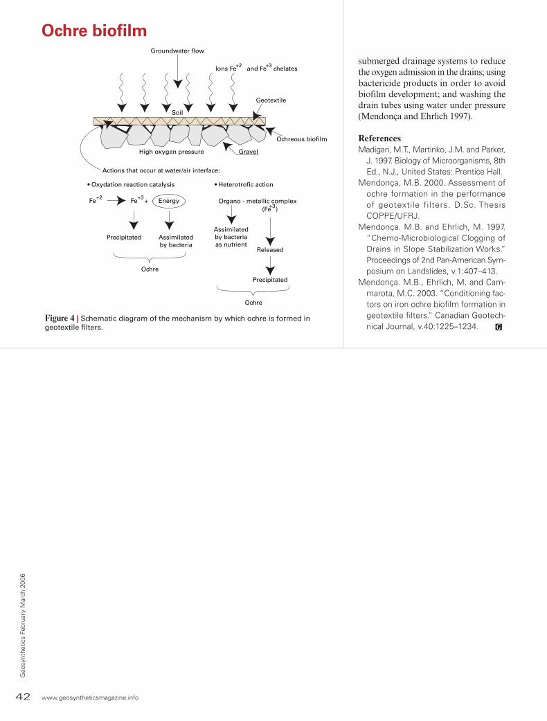
42 www.geosyntheticsmagazine.info
Geo
synt
hetic
s Fe
brua
ry M
arch
200
6
Ions Fe and Fe chelates+2 +3
Geotextile
Ochreous biofilm
High oxygen pressure Gravel
Actions that occur at water/air interface:
• Oxydation reaction catalysis • Heterotrofic action
Fe Fe + Energy+2 +3
Precipitated Assimilated by bacteria
Ochre
Organo - metallic complex (Fe )+3
Assimilatedby bacteriaas nutrient
Released
Precipitated
Ochre
Groundwater flow
Soil
Figure 4 | Schematic diagram of the mechanism by which ochre is formed ingeotextile filters.
Ochre biofilm
submerged drainage systems to reduce the oxygen admission in the drains; using bactericide products in order to avoid biofilm development; and washing the drain tubes using water under pressure (Mendonça and Ehrlich 1997).
ReferencesMadigan, M.T., Martinko, J.M. and Parker,
J. 1997. Biology of Microorganisms, 8th Ed., N.J., United States: Prentice Hall.
Mendonça, M.B. 2000. Assessment of ochre formation in the performance of geotextile filters. D.Sc. Thesis COPPE/UFRJ.
Mendonça. M.B. and Ehrlich, M. 1997. “Chemo-Microbiological Clogging of Drains in Slope Stabilization Works.” Proceedings of 2nd Pan-American Sym-posium on Landslides, v.1:407–413.
Mendonça. M.B., Ehrlich, M. and Cam-marota, M.C. 2003. “Conditioning fac-tors on iron ochre biofilm formation in geotextile filters.” Canadian Geotech-nical Journal, v.40:1225–1234.
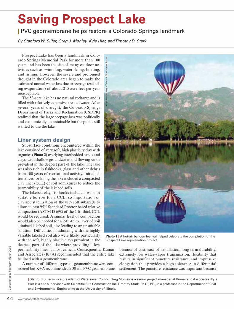
Saving Prospect Lake| PVC geomembrane helps restore a Colorado Springs landmark
By Stanford W. Slifer, Greg J. Monley, Kyle Hier, and Timothy D. Stark
Prospect Lake has been a landmark in Colo-rado Springs Memorial Park for more than 100 years and has been the site of many outdoor ac-tivities such as swimming, water skiing, boating, and fishing. However, the severe and prolonged drought in the Colorado area began to make the estimated annual water loss due to seepage (exclud-ing evaporation) of about 215 acre-feet per year unacceptable.
The 53-acre lake has no natural recharge and is filled with relatively expensive, treated water. After several years of drought, the Colorado Springs Department of Parks and Reclamation (CSDPR) realized that the large seepage loss was politically and economically unsustainable but the public still wanted to use the lake.
Liner system designSubsurface conditions encountered within the
lake consisted of very soft, high plasticity clay with organics (Photo 2) overlying interbedded sands and clays, with shallow groundwater and flowing sands prevalent in the deepest part of the lake. The lake was also rich in fishhooks, glass and other debris from 100 years of recreational activity. Initial al-ternatives for lining the lake included a compacted clay liner (CCL) or soil admixtures to reduce the permeability of the lakebed soils.
The lakebed clay, fishhooks included, was not suitable borrow for a CCL, so importation of clay and stabilization of the very soft subgrade to allow at least 95% Standard Proctor based relative compaction (ASTM D 698) of the 2-ft.-thick CCL would be required. A similar level of compaction would also be needed for a 2-ft.-thick layer of soil admixed lakebed soil, also leading to an unsuitable solution. Difficulties in admixing with the highly variable lakebed soil also were likely, particularly with the soft, highly plastic clays prevalent in the deepest part of the lake where providing a low permeability liner is most critical. Consequently, Kumar and Associates (K+A) recommended that the entire lake be lined with a geomembrane.
A number of different types of geomembrane were con-sidered but K+A recommended a 30-mil PVC geomembrane
Photo 1 | A hot-air balloon festival helped celebrate the completion of the Prospect Lake rejuvenation project.
because of cost, ease of installation, long-term durability, extremely low water-vapor transmission, flexibility that results in significant puncture resistance, and impressive elongation that provides a high tolerance to differential settlement. The puncture resistance was important because
44 www.geosyntheticsmagazine.info
Geo
synt
hetic
s Fe
brua
ry M
arch
200
6
| Stanford Slifer is vice president of Watersaver Co. Inc. Greg Monley is a senior project manager at Kumar and Associates. Kyle
Hier is a site supervisor with Scientific Site Construction Inc. Timothy Stark, Ph.D., P.E., is a professor in the Department of Civil
and Environmental Engineering at the University of Illinois.
All
ph
oto
s co
urt
esy
of
Sci
enti
fic
Sit
e C
on
stru
ctio
n In
c.
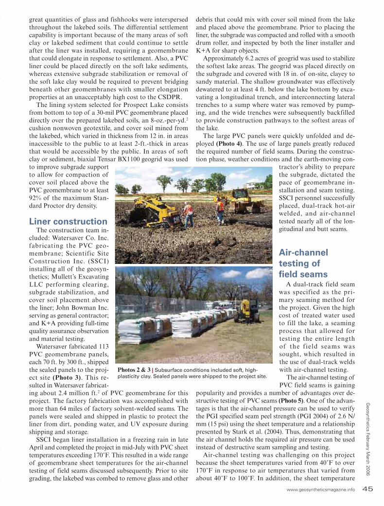
www.geosyntheticsmagazine.info 45
Geosynthetics February M
arch 2006great quantities of glass and fishhooks were interspersed throughout the lakebed soils. The differential settlement capability is important because of the many areas of soft clay or lakebed sediment that could continue to settle after the liner was installed, requiring a geomembrane that could elongate in response to settlement. Also, a PVC liner could be placed directly on the soft lake sediments, whereas extensive subgrade stabilization or removal of the soft lake clay would be required to prevent bridging beneath other geomembranes with smaller elongation properties at an unacceptably high cost to the CSDPR.
The lining system selected for Prospect Lake consists from bottom to top of a 30-mil PVC geomembrane placed directly over the prepared lakebed soils, an 8-oz.-per-yd.2 cushion nonwoven geotextile, and cover soil mined from the lakebed, which varied in thickness from 12 in. in areas inaccessible to the public to at least 2-ft.-thick in areas that would be accessible by the public. In areas of soft clay or sediment, biaxial Tensar BX1100 geogrid was used to improve subgrade support to allow for compaction of cover soil placed above the PVC geomembrane to at least 92% of the maximum Stan-dard Proctor dry density.
Liner constructionThe construction team in-
cluded: Watersaver Co. Inc. fabricating the PVC geo-membrane; Scientific Site Construction Inc. (SSCI) installing all of the geosyn-thetics; Mullett’s Excavating LLC performing clearing, subgrade stabilization, and cover soil placement above the liner; John Bowman Inc. serving as general contractor; and K+A providing full-time quality assurance observation and material testing.
Watersaver fabricated 113 PVC geomembrane panels, each 70 ft. by 300 ft., shipped the sealed panels to the proj-ect site (Photo 3). This re-sulted in Watersaver fabricat-ing about 2.4 million ft.2 of PVC geomembrane for this project. The factory fabrication was accomplished with more than 64 miles of factory solvent-welded seams. The panels were sealed and shipped in plastic to protect the liner from dirt, ponding water, and UV exposure during shipping and storage.
SSCI began liner installation in a freezing rain in late April and completed the project in mid-July with PVC sheet temperatures exceeding 170˚F. This resulted in a wide range of geomembrane sheet temperatures for the air-channel testing of field seams discussed subsequently. Prior to site grading, the lakebed was combed to remove glass and other
debris that could mix with cover soil mined from the lake and placed above the geomembrane. Prior to placing the liner, the subgrade was compacted and rolled with a smooth drum roller, and inspected by both the liner installer and K+A for sharp objects.
Approximately 6.2 acres of geogrid was used to stabilize the softest lake areas. The geogrid was placed directly on the subgrade and covered with 18 in. of on-site, clayey to sandy material. The shallow groundwater was effectively dewatered to at least 4 ft. below the lake bottom by exca-vating a longitudinal trench, and interconnecting lateral trenches to a sump where water was removed by pump-ing, and the wide trenches were subsequently backfilled to provide construction pathways to the softest areas of the lake.
The large PVC panels were quickly unfolded and de-ployed (Photo 4). The use of large panels greatly reduced the required number of field seams. During the construc-tion phase, weather conditions and the earth-moving con-
tractor’s ability to prepare the subgrade, dictated the pace of geomembrane in-stallation and seam testing. SSCI personnel successfully placed, dual-track hot-air welded, and air-channel tested nearly all of the lon-gitudinal and butt seams.
Air-channeltesting offield seams
A dual-track field seam was specified as the pri-mary seaming method for the project. Given the high cost of treated water used to fill the lake, a seaming process that allowed for testing the entire lengthof the f ield seams was sought, which resulted in the use of dual-track welds with air-channel testing.
The air-channel testing of PVC field seams is gaining
popularity and provides a number of advantages over de-structive testing of PVC seams (Photo 5). One of the advan-tages is that the air-channel pressure can be used to verify the PGI specified seam peel strength (PGI 2004) of 2.6 N/mm (15 psi) using the sheet temperature and a relationship presented by Stark et al. (2004). Thus, demonstrating that the air channel holds the required air pressure can be used instead of destructive seam sampling and testing.
Air-channel testing was challenging on this project because the sheet temperatures varied from 40˚F to over 170˚F in response to air temperatures that varied from about 40˚F to 100˚F. In addition, the sheet temperature
Photos 2 & 3 | Subsurface conditions included soft, high-plasticity clay. Sealed panels were shipped to the project site.
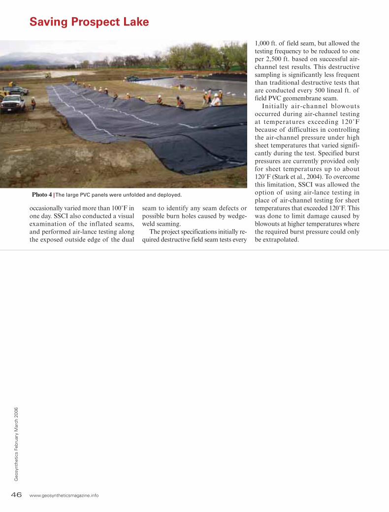
46 www.geosyntheticsmagazine.info
Geo
synt
hetic
s Fe
brua
ry M
arch
200
6
occasionally varied more than 100˚F in one day. SSCI also conducted a visual examination of the inflated seams, and performed air-lance testing along the exposed outside edge of the dual
seam to identify any seam defects or possible burn holes caused by wedge-weld seaming.
The project specifications initially re-quired destructive field seam tests every
1,000 ft. of field seam, but allowed the testing frequency to be reduced to one per 2,500 ft. based on successful air-channel test results. This destructive sampling is significantly less frequent than traditional destructive tests that are conducted every 500 lineal ft. of field PVC geomembrane seam.
Initially air-channel blowoutsoccurred during air-channel testing at temperatures exceeding 120˚Fbecause of difficulties in controlling the air-channel pressure under high sheet temperatures that varied signifi-cantly during the test. Specified burst pressures are currently provided only for sheet temperatures up to about 120˚F (Stark et al., 2004). To overcome this limitation, SSCI was allowed the option of using air-lance testing in place of air-channel testing for sheet temperatures that exceeded 120˚F. This was done to limit damage caused by blowouts at higher temperatures where the required burst pressure could only be extrapolated.
Saving Prospect Lake
Photo 4 | The large PVC panels were unfolded and deployed.
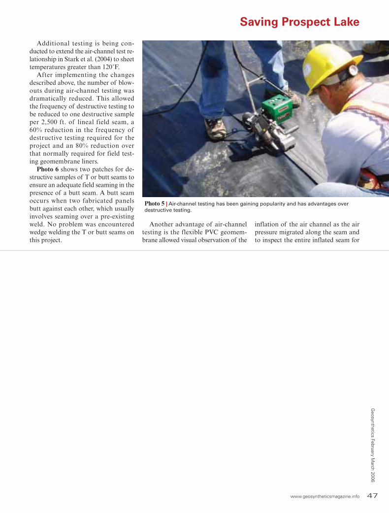
www.geosyntheticsmagazine.info 47
Geosynthetics February M
arch 2006
Additional testing is being con-ducted to extend the air-channel test re-lationship in Stark et al. (2004) to sheet temperatures greater than 120˚F.
After implementing the changes described above, the number of blow-outs during air-channel testing was dramatically reduced. This allowed the frequency of destructive testing to be reduced to one destructive sample per 2,500 ft. of lineal field seam, a 60% reduction in the frequency of destructive testing required for the project and an 80% reduction over that normally required for field test-ing geomembrane liners.
Photo 6 shows two patches for de-structive samples of T or butt seams to ensure an adequate field seaming in the presence of a butt seam. A butt seam occurs when two fabricated panels butt against each other, which usually involves seaming over a pre-existing weld. No problem was encountered wedge welding the T or butt seams on this project.
Another advantage of air-channel testing is the flexible PVC geomem-brane allowed visual observation of the
inflation of the air channel as the air pressure migrated along the seam and to inspect the entire inflated seam for
Saving Prospect Lake
Photo 5 | Air-channel testing has been gaining popularity and has advantages over destructive testing.
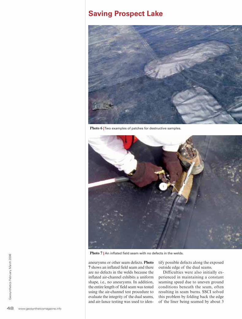
48 www.geosyntheticsmagazine.info
Geo
synt
hetic
s Fe
brua
ry M
arch
200
6
aneurysms or other seam defects. Photo 7 shows an inflated field seam and there are no defects in the welds because the inflated air-channel exhibits a uniform shape, i.e., no aneurysms. In addition, the entire length of field seam was tested using the air-channel test procedure to evaluate the integrity of the dual seams, and air-lance testing was used to iden-
tify possible defects along the exposed outside edge of the dual seams.
Difficulties were also initially ex-perienced in maintaining a constant seaming speed due to uneven ground conditions beneath the seam, often resulting in seam burns. SSCI solved this problem by folding back the edge of the liner being seamed by about 3
Saving Prospect Lake
Photo 6 | Two examples of patches for destructive samples.
Photo 7 | An inflated field seam with no defects in the welds.
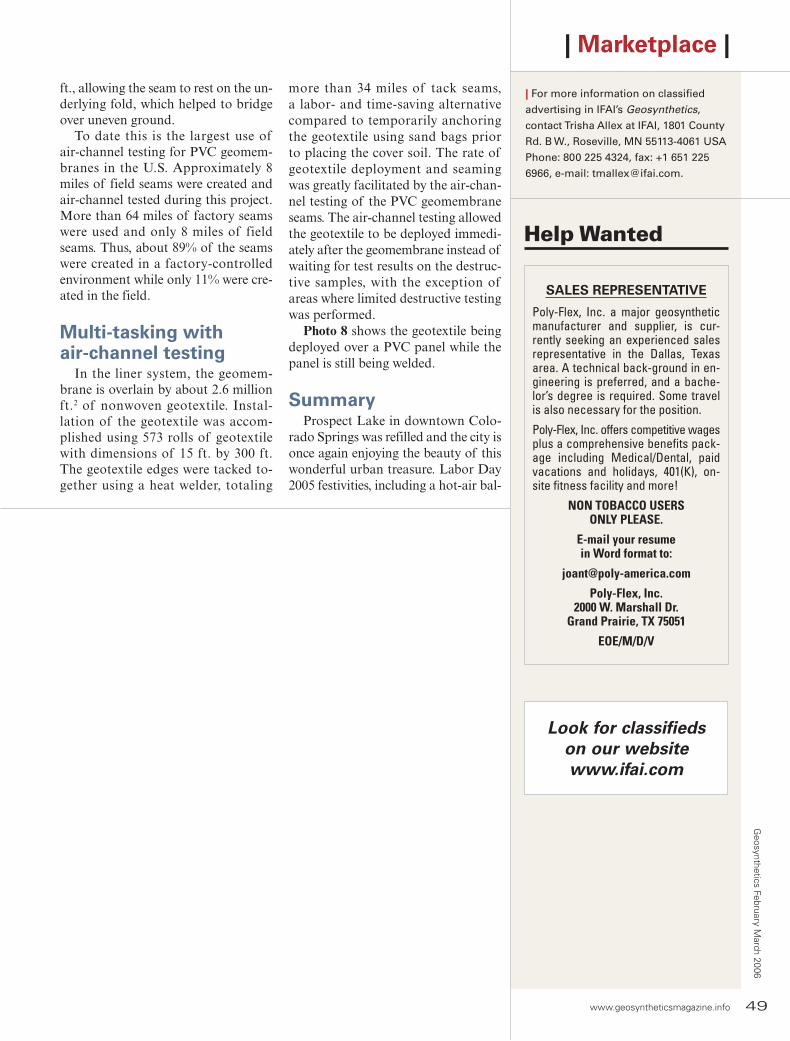
www.geosyntheticsmagazine.info 49
Geosynthetics February M
arch 2006
ft., allowing the seam to rest on the un-derlying fold, which helped to bridge over uneven ground.
To date this is the largest use of air-channel testing for PVC geomem-branes in the U.S. Approximately 8 miles of field seams were created and air-channel tested during this project. More than 64 miles of factory seams were used and only 8 miles of field seams. Thus, about 89% of the seams were created in a factory-controlled environment while only 11% were cre-ated in the field.
Multi-tasking withair-channel testing
In the liner system, the geomem-brane is overlain by about 2.6 million ft.2 of nonwoven geotextile. Instal-lation of the geotextile was accom-plished using 573 rolls of geotextile with dimensions of 15 ft. by 300 ft. The geotextile edges were tacked to-gether using a heat welder, totaling
| Marketplace |
| For more information on classified
advertising in IFAI’s Geosynthetics,
contact Trisha Allex at IFAI, 1801 County
Rd. B W., Roseville, MN 55113-4061 USA
Phone: 800 225 4324, fax: +1 651 225
6966 , e-mail: [email protected].
Help Wanted
SALES REPRESENTATIVE
Poly-Flex, Inc. a major geosynthetic manufacturer and supplier, is cur-rently seeking an experienced sales representative in the Dallas, Texas area. A technical back-ground in en-gineering is preferred, and a bache-lor’s degree is required. Some travel is also necessary for the position.
Poly-Flex, Inc. offers competitive wages plus a comprehensive benefi ts pack-age including Medical/Dental, paid vacations and holidays, 401(K), on-site fi tness facility and more!
NON TOBACCO USERSONLY PLEASE.
E-mail your resumein Word format to:
Poly-Flex, Inc.2000 W. Marshall Dr.
Grand Prairie, TX 75051
EOE/M/D/V
Look for classifiedson our website www.ifai.com
more than 34 miles of tack seams, a labor- and time-saving alternative compared to temporarily anchoring the geotextile using sand bags prior to placing the cover soil. The rate of geotextile deployment and seaming was greatly facilitated by the air-chan-nel testing of the PVC geomembrane seams. The air-channel testing allowed the geotextile to be deployed immedi-ately after the geomembrane instead of waiting for test results on the destruc-tive samples, with the exception of areas where limited destructive testing was performed.
Photo 8 shows the geotextile being deployed over a PVC panel while the panel is still being welded.
SummaryProspect Lake in downtown Colo-
rado Springs was refilled and the city is once again enjoying the beauty of this wonderful urban treasure. Labor Day 2005 festivities, including a hot-air bal-
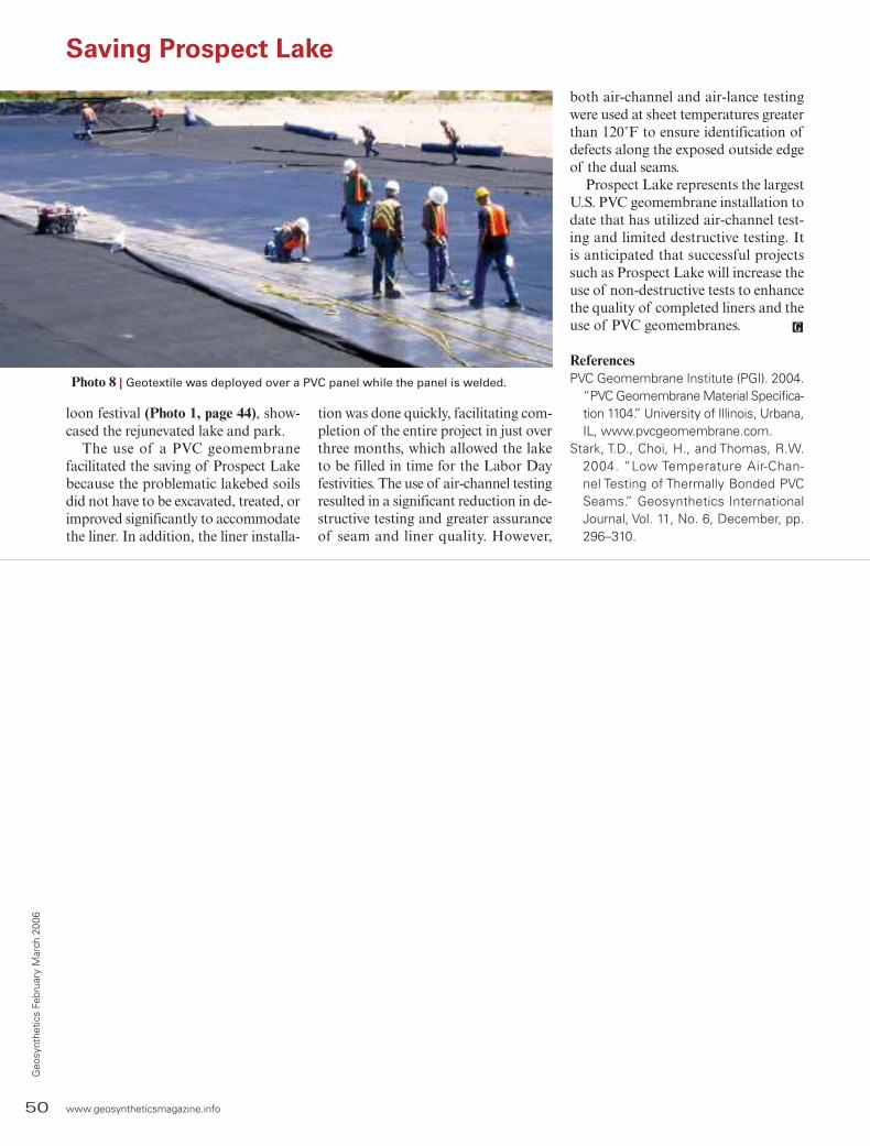
50 www.geosyntheticsmagazine.info
Geo
synt
hetic
s Fe
brua
ry M
arch
200
6
loon festival (Photo 1, page 44), show-cased the rejunevated lake and park.
The use of a PVC geomembrane facilitated the saving of Prospect Lake because the problematic lakebed soils did not have to be excavated, treated, or improved significantly to accommodate the liner. In addition, the liner installa-
tion was done quickly, facilitating com-pletion of the entire project in just over three months, which allowed the lake to be filled in time for the Labor Day festivities. The use of air-channel testing resulted in a significant reduction in de-structive testing and greater assurance of seam and liner quality. However,
Saving Prospect Lake
Photo 8 | Geotextile was deployed over a PVC panel while the panel is welded.
both air-channel and air-lance testing were used at sheet temperatures greater than 120˚F to ensure identification of defects along the exposed outside edge of the dual seams.
Prospect Lake represents the largest U.S. PVC geomembrane installation to date that has utilized air-channel test-ing and limited destructive testing. It is anticipated that successful projects such as Prospect Lake will increase the use of non-destructive tests to enhance the quality of completed liners and the use of PVC geomembranes.
ReferencesPVC Geomembrane Institute (PGI). 2004.
“PVC Geomembrane Material Specifica-tion 1104.” University of Illinois, Urbana, IL, www.pvcgeomembrane.com.
Stark, T.D., Choi, H., and Thomas, R.W. 2004. “Low Temperature Air-Chan-nel Testing of Thermally Bonded PVC Seams.” Geosynthetics International Journal, Vol. 11, No. 6, December, pp. 296–310.

www.geosyntheticsmagazine.info 51
Geosynthetics February M
arch 2006
| Geosynthetic Institute |
GSI Board of Directorsmajority decides issues that come before the board. Members of the GSI board can be reelected since the Bylaws do not address this topic.
The accompanying table presents the history of the GSI Board of Di-rectors. As indicated, the three posi-tions up for election in 2006 are for consultants/testing labs, geomem-brane/GCLs, and one at-large posi-tion. The board meets at least once per year and we have teleconferences on a regular basis or as-needed on a specific topic.
We would like to take this oppor-tunity to sincerely thank all of these individuals for their service. As well, we thank their respective organiza-tions for allowing them the time for this commitment. While GSI board members serve in an advisory capac-ity, we have invariably taken their advice on thorny and sensitive issues. We at GSI sincerely appreciate their commitment and involvement.
Bob KoernerGeorge KoernerGrace Hsuan
Per the GSI Bylaws we are required to have a nine-person Board of Di-rectors from each of the following membership groups: agencies, own-ers, consultant and testing laborato-ries, resin and additive companies, geomembrane and geosynthetic clay liner (GCL) companies, geotextiles and geogrid companies, international members, and two at-large from the entire membership. Each member of the board serves for three years, and each year three different posi-tions come up for election. A simple
GSI Board of Directors
1996 1997 1998 1999 2000 2001 2002 2003 2004 2005 2006 2007
AGENCY D. Jaros D. Jaros D. Jaros D. Jaros D. Jaros D. Jaros D. Jaros D. Jaros D. Jaros D. Jaros D. Jaros D. Jaros
OWNER D. Spikula D. Spikula D. Spikula D. Spikula R. Jones T. Eith T. Eith T. Eith T. Eith T. Eith T. Eith —
CONSULTANT L.Overmann
L.Overmann D. Stulgis D. Stulgis D. Stulgis D. Stulgis D. Stulgis D. Stulgis D. Stulgis D. Stulgis — —
RESIN P. Maeger P. Maeger P. Maeger R. Bobsein R. Bobsein R. Bobsein R. Bobsein R. Bobsein R. Bobsein R. Bobsein R. Bobsein R. Bobsein
GM/GCL F. Struve B. Torres B. Torres B. Torres B. Ramsey B. Ramsey B. Ramsey J. Olsta J. Olsta J. Olsta — —
GT/GG J. Paulson(Chair)
J. Paulson(Chair) J. Paulson J. Paulson J. Paulson G. Willibey G. Willibey/
M. Theisen M. Theisen B. Ramsey(Chair)
R. Ramsey(Chair)
B. Ramsey —
INTERNATIONAL P. Rimoldi P. Rimoldi P. Rimoldi P. Rimoldi P. Rimoldi P. Rimoldi K. von Maubeuge
K. von Maubeuge
K. von Maubeuge
K. von Maubeuge
K. von Maubeuge
K. von Maubeuge
AT-LARGE S. Allen S. Allen S. Allen(Chair)
S. Allen(Chair) S. Allen S. Allen S. Allen
(Chair)S. Allen(Chair) S. Allen S. Allen S. Allen —
AT-LARGE G. Kolbasuk G. Kolbasuk G. Kolbasuk G. Kolbasuk G. Kolbasuk(Chair)
G. Kolbasuk(Chair) D. Suits D. Suits D. Suits D. Suits — —
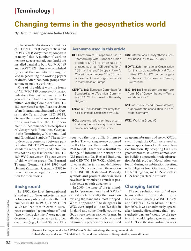
| Terminology |
Changing terms in the geosynthetics worldBy Helmut Zanzinger and Robert Mackey
The standardization committees of CEN/TC 189 (Geosynthetics) and ISO/TC 221 (Geosynthetics) cooperate in many fields. A number of working items (e.g., geosynthetic standards) are installed parallel in both CEN/TC 189 and ISO/TC 221. This is accomplished by one of the committees taking the lead in generating the working papers or drafts. After that, both groups offer comments on the work item.
One of the oldest working items of CEN/TC 189 completed a major milestone this past summer after 15 years of its initiation within the com-mittee. Working Group 2 of CEN/TC 189 completed a significant revision of an International Standard on Geo-synthetic Terminology. ISO 10318, Geosynthetics—Terms and defini-tions, was based on the IGS docu-ment, “Recommended Descriptions of Geosynthetic Functions, Geosyn-thetic Terminology, Mathematical and Graphical Symbols.” The ability to develop a consensus between par-ticipating ISO/TC 221 members in the standard’s scope, terms, and definition was not an easy task for the CEN/TC 189 WG2 convener. The conveners of this working group, Dr. Bernard Thamm, Germany (1990–1996) and Helmut Zanzinger, Germany (1996 to present), deserve significant recogni-tion for their efforts.
BackgroundIn 1992, the first International
Standard on Geosynthetic Termi-nology was published under the ISO number 10318. In 1997, CEN/TC 189 WG2 realized that in certain Euro-pean countries “geomembranes” and “geosynthetic clay liners” were not un-derstood in the same way as in other countries (e.g., United States). This
issue was the most difficult item to resolve. The working group continued its effort to revise the standard. From 1998 to 2000, there was a fruitful ex-change of information between the IGS president, Dr. Richard Bathurst, and CEN/TC 189 WG2, which re-sulted in similar terms and definitions of the IGS document and the revision of the ISO 10318 standard. Property symbols and product abbreviations have been harmonized as much as pos-sible between both documents.
In 2000, the issue of the terminol-ogy for “geomembranes” and “GCLs” caused such difficulty that work on revising the standard almost stopped. What happened? The delegates in WG2 were surprised to realize that in England and some Nordic countries, GCLs were seen as geomembranes. In all other countries, only polymeric and bituminous geomembranes are used
as geomembranes and never GCLs, even though the GCLs were used in similar applications for the same bar-rier function. By accepting GCLs as geomembranes, WG2 was admonished for building a potential trade obstruc-tion for this product. No solution was found during an arbitration meeting with delegates from Germany, France, United Kingdom, and CEN officials at CEN headquarters in Brussels.
Changing termsThe only solution was to find new
terms with appropriate definitions. In a common meeting of ISO/TC 221 and CEN/TC 189 in Milan in Octo-ber 2000, it was unanimously agreed, after lengthy discussions, that “geo-synthetic barriers” would be the new term. It would replace geomembranes and GCLs in the standardization work
CE: Comformite Europeenne, as in “conforming with European Union standards.” CE is often used in phrases such as “CE certification,” “CE marking,” and “European Union’s CE-certification process.” The CE mark is essential for use of geosynthetics in many areas of Europe.
CEN/TC 189: European Committee for Standardization/Technical Commit-tee 189. CEN is based in Brussels, Belgium.
EN: as in “EN standards,” voluntary tech-nical standards established by CEN.
GCL: geosynthetic clay liner, a term that may be on its way to obsoles-cence, according to this story.
IGS: International Geosynthetics Soci-ety, based in Easley, SC, USA
ISO/TC 221: International Organization for Standardization/Technical Com-mittee 221. TC 221 concerns geo-synthetics. ISO is based in Geneva, Switzerland.
ISO 10318: The document number from ISO’s “Geosynthetics — Terms and definitions.”
IVG: Industrieverband Geokunststoffe, a geosynthetic association in Lem-förde, Germany.
WG2: Working Group #2
Acronyms used in this article
52 www.geosyntheticsmagazine.info
Geo
synt
hetic
s Fe
brua
ry M
arch
200
6
| Helmut Zanzinger works for SKZ-TeConA GmbH, Würzburg, Germany; www.skz.de.
Robert Mackey works for S2Li, Maitland, Fla., and is an advisor to Geosynthetics; www.s2Li.com.

www.geosyntheticsmagazine.info 53
Geosynthetics February M
arch 2006
of CEN and ISO. Incorporating the functional term “barrier” after “geo-synthetic” created a more descriptive term for geosynthetic materials used to prevent the migration of liquids or gases. Geosynthetic barriers were subdivided into polymeric geo-synthetic barriers, bituminous geosynthetic barriers, and clay geosynthetic barriers.
The terms “geomembrane” and “geosynthetic clay liners” (GCLs) no longer exist in the international terminology standard developed in as-sociation with CEN and ISO. This major development of revised geosyn-thetic terminology was approved and published by ISO in July 2005.
ISO 10318 also includes the addi-tion of geosynthetic pictograms devel-oped by CEN/TC 189. They are based on pictograms from the German IVG. These pictograms were requirements of the European Union’s CE-certification process. Manufacturers of geosynthetic products are required to provide accom-
panying documents (harmonized data sheets) of each certified product in the language of all European members. The objective of ISO 10318 is to use unique pictograms for applications and func-tions, harmonized terminology, and
standardized symbols for properties to allow geosynthetics to be readable and understandable in any language.
Since 2000, ISO/TC 221 has be-come more involved in terminology issues and the development of inter-national terminology standardiza-tion, under a CEN lead. The most significant change is that the terms “geomembrane” and “geosynthetic clay liner” (GCL) disappeared in EN and ISO standards. The members of ISO/TC 221 and CEN/TC 189 real-
| Terminology |
The terms “geomembrane” and“geosynthetic clay liners” nolonger exist in the internationalterminology standard …
ize that these terms have been a part of the geosynthetic language for so long that they may never be replaced by “geosynthetic barriers.” However, after three long years of discussions, the development of the terms “poly-
meric geosynthetic barriers,” “bituminous geosynthetic barriers,” and “clay geosyn-thetic barriers” was the only solution. The acceptance and utilization of these terms will be based on the future use of
ISO standards and those in the geo-synthetic field.
Contact informationFor more information regarding inter-
national standards on geosynthetic termi-nology, please feel free to contact: CEN/TC 189 WG2 convener, Helmut Zanzinger, Germany, [email protected]
ISO/TC 221 WG2 convener, Bob Mackey, United States, [email protected]
Please mail check orders to: IFAI, 1801 County Road B W., Roseville, MN 55113-4061
For quickest response, fax your “Bill Me” order to: +1 651 631 9334
SUBSCRIBE TO GEOSYNTHETICS
Title (please check):❑ Owner/Corporate executive❑ Chief/Staff Engineer❑ Geotechnical Engineer❑ Civil Engineer❑ Research/Development Professional❑ Other (please specify)___________________
Type of business (please check all that apply):❑ Engineering Firm/Engineering Private Practice❑ Contractor❑ Geosynthetic Installer❑ Installation/Fabrication Equipment Supplier❑ Geosynthetic Producer/Distributor❑ Other (please specify)____________________
My method of payment (please check one):
❑ I’ve enclosed a check (please make checks payable to IFAI in U.S. dollars drawn on a U.S. bank)
❑ Please send me a billPlease note: IFAI accepts Visa, MasterCard and American Express credit cards. To pay by credit card, please call +1 651 222 2508 or 800 225 4324 or Subscribe online at www.geosyntheticsmagazine.info
Name
Company Phone#
Address
E-mail Fax#
Signature Date
❑ YES, I would like to subscribe to Geosynthetics! Subscription prices are: $61/year US, $74/year Canada/Mexico, $102/year outside North America

54 www.geosyntheticsmagazine.info
Geo
synt
hetic
s Fe
brua
ry M
arch
200
6
| Calendar |
20–23 FebruaryEC06, Long Beach, Calif.
The International Erosion Control Association (IECA) sponsors this event about stormwater management, erosion control, and affiliated environ-mental issues. Two days of training courses and two days of exhibits and technical sessions are offered.
For more information, contact International Erosion Control Asso-ciation, 3001 S. Lincoln Ave, Ste. A, Steamboat Springs, CO 80487, United States; +1 970 879 3010, ext. 15; fax +1 970 879 8563; e-mail: [email protected]; Web site: www.ieca.org.
26 February–1 March GeoCongress 2006, Atlanta
American Society of Civil Engineers and the Geo Institute are pleased to an-nounce GeoCongress 2006: “Geotechni-cal Engineering in the Information Tech-nology Age.” The event will be held at the Hyatt Regency Hotel in Atlanta, Ga.
For more information: www.asce.org/conferences/geocongress06/
6–8 JuneGeoShanghai 2006, Shanghai, China
China has come a long way but has a steep path ahead. Engineering proj-ects executed in the next 10 years will largely influence the long-term suc-cess of the current national plans for infrastructure stability, the creation of a middle class, and a firm place atop the world’s stage. GeoShanghai will explore ways the nation has developed and examine proactive solutions for future development.
For more information, visit the Web site at: www.geoshanghai.org.
14–16 JuneASTM Committee D35Summer Meeting, Toronto
ASTM’s Committee D35 on Geo-synthetics meets twice yearly to further standards development, present educa-tional workshops, and promote dialogue among geosynthetic professionals.
ASTM International, Christine Sierk, 100 Barr Harbor Dr., West Con-shohockern, PA 19428-2959, United States; +1 610 832 9737; e-mail: [email protected]; Web site: www.astm.org.
10–13 September2006 APWA International Public Works Congress & Exposition, Kansas City, Mo.
The American Public Works Asso-ciation’s annual event gives visitors an excellent opportunity to network with and learn from leaders in the public works field. Thousands of officials and professionals attend, sharing their infrastructure planning, design, main-tenance, and management experience.
NOTE: APWA 2006 was scheduled originally for New Orleans. Due to Hurricane Katrina’s damage, the event has been moved to Kansas City during the same dates.
For more information, contact Dana Priddy, American Public Works Association, 2345 Grand Blvd., Ste. 500, Kansas City, MO 64108-2641, United States; +1 816 595 5241; fax +1
816 472 1610; e-mail: [email protected]; Web site: www.apwa.net.
18–22 September8th International Conference onGeosynthetics, Yokohama, Japan
The International Geosynthetics Society’s (IGS) showcase conference offers an exceptional opportunity for dialogue among the various disciplines related to geosynthetics (geotechnical, environmental, and civil engineering; hydraulics; geology; etc.). It will provide perspectives on and overview of techni-cal innovations by giving the widest pos-sible forum to engineers and researchers and by welcoming papers devoted to new techniques and applications.
For more information, visit the conference Web site: www.8icg-yokohama.org.
16-19 January 2007Geosynthetics 2007, Washington, D.C.
Geosynthetics 2007 will be held at the Hilton Washington in Washing-ton, D.C., January 16–19, 2007, imme-diately preceding the Transportation Research Board’s annual meeting.
The conference and exhibition, themed Geo Solutions for the Environ-ment, Transportation and Homeland Security, will provide a platform for the discussion of practices, applica-tions, regulatory issues, and the con-struction outlook shaping the future of the geosynthetics community.
More than 1,200 professionals representing regulatory and gov-ernment agencies, research, design, engineering, manufacturing, con-struction and installation fields of geosynthetic materials and products are expected to attend more than 150 valuable educational programs.
A Call for Abstracts is scheduled for February 1–April 1, 2006, includ-ing technical papers, discussion pan-els, student papers, and short courses covering all aspects of geosynthetic materials, research, performance, testing, design, engineering, con-struction, case histories, and field experience with a special focus on environment and transportation.
The exhibition features more than 100 companies showcasing their latest fabrics, technologies, services, equipment, and more. A value-added bonus for participants includes the opportunity to attend the Geosynthetics Research Institute 20th Anniversary Conference focus-ing on Geosynthetics in Homeland Security held in conjunction with Geosynthetics 2007.
Geosynthetics 2007 is organized by the Industrial Fabrics Asso-ciation International (IFAI) and Geosynthetic Materials Associa-tion (GMA). The event is held in cooperation with the North Ameri-can Geosynthetic Society (NAGS) under the auspices of the Interna-tional Geosynthetics Society (IGS) and the Geosynthetics Research Institute (GRI).
To submit an abstract or proposal, or to subscribe to Geosynthetics 2007 E-News Bulletins, visit www.geoshow.info or contact Jill M. Rut-ledge, Secretary-General, IFAI, 1801 County Road B. West, Roseville, MN 55113-4061; + 1 651 225 6981; fax: + 1 651-631-9334; e-mail: [email protected].

56 www.geosyntheticsmagazine.info
Geo
synt
hetic
s Fe
brua
ry M
arch
200
6
Geosynthetics (formerly GFR) is an international, bi-monthly publica-tion for civil engineers, contractors and government agencies in need ofexpert information on geosynthetic engineering solutions. Geosyntheticspresents articles from field professionals for innovative, exemplary practice.
| Final Inspection |
Making the world betterI couldn’t pass up this job.I was hired as the new editor for a new(ly named) magazine called
Geosynthetics (formerly GFR) in December. And just a few days later, myfirst assignment took me to Las Vegas.
Las Vegas? Four days in Las Vegas spending time with … engineers!?Listening to engineers, talking with engineers, listening to engineers talking
with other engineers. For four days. Nonstop.The stereotype was vivid to me. Engineers? If they aren’t really boring, they
sometimes pretend to be. If an answer doesn’t need to be complex, they will make it exceedingly complicated.
You want to know the honest truth? It was terrific.I speak not in jest when I tell you that every person I talked to during
those four days at the NAGS 2005 / GRI 19 Geosynthetics Conference was helpful, forthcoming, and appeared to me to want to be of genuine service––of service to me as a new editor, of service to this magazine, and of serviceto their profession.
They want to be of service to their profession. How impressive is that?It was the sense of wanting to help that I witnessed in the hallways, seminar
rooms, and exhibit areas at this conference. These were people who wanted to make a difference. These were people who wanted to make their profession better. These were people who wanted to use their engineering skills andproducts to literally make the world better––at least structurally.
So for four days, I listened––and worked hard to absorb and learn––asengineer after engineer went on and on about geosynthetic-reinforced walls, geosynthetics in heap leach systems, geosynthetics in pavement systems,“hot topics” in geosynthetics …
Four days in Las Vegas spending time with hundreds of engineers? Ienjoyed every minute!
In this, my first issue, I want to again say a genuine “thank you” to all the industry veterans, readers, and contributors who have generously shared their time and expertise with me. And thanks in advance to all of the others who will make future contributions to the magazine and help build this industry.
| Ron Bygness, Editor+1 651 225 [email protected]
56 www.geosyntheticsmagazine.info
Geo
synt
hetic
s Fe
brua
ry M
arch
200
6
| Geosynthetics encourages your contributions of case histories, photos and field tips. For submittal guidelines, contact
Ron Bygness at 800 225 4324 or +1 651 225 6988; e-mail: [email protected].