Embed Size (px)
Citation preview
RSC Advances
PAPER
Publ
ishe
d on
08
Sept
embe
r 20
14. D
ownl
oade
d by
New
Yor
k U
nive
rsity
on
19/1
0/20
14 0
7:12
:33.
View Article OnlineView Journal | View Issue
Transition metal
State Key Laboratory of Catalysis, Dalian
Academy of Sciences, Dalian National Labo
Road, Dalian, 116023, China. E-mail: canli
ac.cn; Fax: +86-411-84694447; Tel: +86-411
† Electronic supplementary informa10.1039/c4ra07498j
‡ These authors contributed equally to th
Cite this: RSC Adv., 2014, 4, 47383
Received 23rd July 2014Accepted 8th September 2014
DOI: 10.1039/c4ra07498j
www.rsc.org/advances
This journal is © The Royal Society of C
(Ni, Fe, and Cu) hydroxidesenhanced a-Fe2O3 photoanode-based photofuelcell†
Ruifeng Chong,‡ Zhiliang Wang,‡ Jun Li, Hongxian Han, Jingying Shi and Can Li*
Photofuel cells have been demonstrated to be a promising strategy for generating electricity using biomass.
Here, we present a photofuel cell with a visible light a-Fe2O3 based photoanode that can be directly
powered by a variety of biomasses such as methanol, glycerol, glucose, cellubiose and starch. The
photocurrent density and power density of the photofuel cell are significantly enhanced by loading
cocatalysts (metal hydroxides, e.g. Ni(OH)2) on the a-Fe2O3 photoanode. The power density of the
photofuel cell powered by glucose is enhanced over two times from 0.082 mA cm�2 for a-Fe2O3 to
0.18 mW cm�2 for Ni(OH)2/a-Fe2O3 photoanode.
Introduction
The utilization of abundant biomass as an energy source canprevent environmental pollution and reduce the dependenceon fossil resources.1,2 The technological challenge is to sus-tainably capture biomass energy using green processes.Direct alcohol fuel cells (DAFCs) with potentials of highpower density and being pollution-free offer a possiblesolution to this problem.3,4 Although DAFCs powered by lowmolecular weight alcohols (usually methanol or ethanol)have been demonstrated to be practically feasible, biomass-derived compounds, such as glucose, polysaccharide, andcellulose, have not been reported as fuels for DAFCs. This isbecause of the low activity of catalysts in the activation of theC–C bonds and the oxidation of biomass at low tempera-tures.5,6 Biofuel cells can be powered by various biomasses atlow temperatures; however, low electric power output,limited lifetime and rigorous reaction conditions seriouslyhinder their applications.7,8
A photofuel cell (PFC) mainly consists of a semiconductorphotoanode, a cathode, electrolyte and fuels.9–14 With PFCtechnology, biomass as a fuel can be oxidized on the photo-anode under light irradiation and oxygen is reduced on thecounter electrode through an external circuit, generatingelectricity. In essence, PFC is different from the fuel cellsreported previously and widens the range of biomass fuels for
Institute of Chemical Physics, Chinese
ratory for Clean Energy, 457 Zhongshan
@dicp.ac.cn; Web: http://www.canli.dicp.
-84379070
tion (ESI) available. See DOI:
is work.
hemistry 2014
electricity generation. Thus, various biomasses, such as glyc-erol, glucose, saccharides, proteins, and ammonia, can beused as fuels for PFCs with a TiO2 photoanode. Previous workhas demonstrated that PFCs can convert biomass into elec-tricity even at low ambient temperatures. However, TiO2 andWO3 with band gaps of 3.2 eV and 2.8 eV, respectively, use onlya small proportion of solar irradiation.15 Therefore, semi-conductors with wide ranges of light absorption are highlydesired for PFCs.
Hematite (a-Fe2O3), with an optical band gap of 2.1 eV, is apromising material for photoanodes due to its abundance,ecofriendly nature, and photochemical stability in basic elec-trolytes.16–18 However, its short excited state lifetime (�1 ps)and the small hole diffusion length (�2 to 4 nm) signicantlyhinders its efficiency in charge separation and collection. Toovercome these problems, various strategies have been adop-ted, including reducing the size,19,20 doping21–23 and loadingcocatalysts.24–26 Among these strategies, loading cocatalysts isthe most efficient method for photoelectrochemical watersplitting. However, a-Fe2O3 loaded with an appropriatecocatalyst that can distinctly enhance biomass oxidation hasnot been reported.
In this work, we present a PFC with a-Fe2O3 based photo-anodes that directly converts biomass-derived compoundssuch as methanol, glucose, glycerol, cellubiose, and starch. Toimprove the PFC efficiency and the stability of a-Fe2O3 pho-toanode, transition metal hydroxides Ni(OH)2, Fe(OH)3, andCu(OH)2 are loaded as biomass oxidation cocatalysts. It wasfound that cocatalysts can remarkably enhance the photo-response and stability of bare a-Fe2O3 for biomass oxidation,which demonstrates an example of stimulating a PFC byloading an efficient cocatalyst on the photoanode.
RSC Adv., 2014, 4, 47383–47388 | 47383
RSC Advances Paper
Publ
ishe
d on
08
Sept
embe
r 20
14. D
ownl
oade
d by
New
Yor
k U
nive
rsity
on
19/1
0/20
14 0
7:12
:33.
View Article Online
ExperimentalMaterials
All the chemicals were of analytical grade and were used aspurchased. Solutions were prepared using high purity water(Millipore Milli-Q purication system, resistivity > 18 MU cm).FTO (uorine-doped tin oxide) conductive glass was purchasedfrom Nippon Sheet Glass Company 5 (Japan) and was ultra-sonically cleaned with acetone, ethanol and deionized water for20 min each in sequence prior to use.
Preparation of the Fe2O3 lms
a-Fe2O3 lms were deposited on an F-doped SnO2 (FTO)substrate electrode using a modied chemical bath depositionmethod reported elsewhere.27 Specically, 0.2 mol L�1 FeCl3(FeCl3$6H2O, $99%, Shanghai Chemical) aqueous solution(10 mL) and 0.3 mol L�1 NH2CONH2 (98%, Shanghai Chemical)were mixed in a 50 mL glass beaker and heated at 100 �C for 4 h.FTO was placed vertically in this beaker with the conductingedge facing the wall of the beaker. Aer the reaction, the lmformed on FTO was thoroughly rinsed with high purity waterand annealed at 500 �C for 3 h to obtain the desired phase.Finally, the prepared sample was further annealed at 750 �C for10 min.
Fabrication of M(OH)x/Fe2O3 photoanode
Ni(OH)2 was deposited onto a-Fe2O3 by a successive ionic layeradsorption and reaction method. In a typical synthesis, a-Fe2O3
electrodes were dipped into 0.1 mol L�1 Ni(NO3)2 ($98.5%,Shanghai Chemical) solution for 40 s, followed by drying withcompressed air. Then, the electrodes were dipped into 1mol L�1 KOH solution for another 40 s and dried withcompressed air. Next, the prepared sample was washed withethanol and dried at 60 �C for 1 h in air. Fe(OH)3/a-Fe2O3 andCu(OH)2/a-Fe2O3 samples were prepared using the samemethod without further heat treatment.
Characterization of the electrodes
The prepared samples were characterized by X-ray powderdiffraction (XRD) on a Rigaku D/Max-2500/PC powder diffrac-tometer using Cu Ka radiation (operating voltage: 40 kV, oper-ating current: 20 mA, scan rate: 5� min�1). The UV-visiblediffuse reectance spectra were recorded on a UV-visible spec-trophotometer (JASCO V-550) and calibrated by the Kubelka-Munk method. The morphologies of the electrodes wereexamined using a Quanta 200 FEG scanning electron micro-scope (SEM) equipped with an energy dispersive spectrometer(accelerating voltage of 20 kV). Transmission electron micros-copy (TEM) images were taken on a Tecnai G2 Spirit (FEIcompany) using an accelerating voltage of 120 kV. High-reso-lution transmission electron microscopy (HRTEM) images wereacquired on Tecnai G2 F30 S-Twin (FEI company) with anaccelerating voltage of 300 kV. The liquid products quantitativeanalysis was carried out using HPLC (Agilent 1200) withrefractive index (RI) detector and ultraviolet (UV, l ¼ 210 nm)
47384 | RSC Adv., 2014, 4, 47383–47388
detector for arabinose, erythrose, glyceraldehyde, glyco-laldehyde, glycolate and formate. The reactants and productswere separated through an ion exclusion column (Alltech OA-1000) heated at 55 �C. The eluent was a solution of H2SO4
(0.005 mol L�1). Products were identied through comparisonwith standard samples, which were obtained from Sigma-Aldrich.
Photoelectrochemical and electrochemical measurements
All the photoelectrochemical measurements were carried out ina three-electrode cell with a at quartz window to facilitate theillumination of the photoelectrode surface. The working elec-trode was a-Fe2O3, and Hg/HgCl2 (saturated KCl) and a Pt plate(2 cm � 4 cm) were used as a reference and counter electrode,respectively. A Naon membrane was used to prevent thecrossover between the anode and cathode. The illuminationsource was a 300 W Xe arc lamp and the light intensity at thesurface of the electrodes was 300 mW cm�2. The electro-chemical measurements were performed on a CHI 760D elec-trochemical workstation (CHI, Shanghai) at room temperature.The electrolyte was 1 mol L�1 KOH solution with/without0.025 mol L�1 glucose or methanol (10 vol%), glycerol(0.025 mol L�1), cellubiose (0.025 mol L�1) and starch (1 wt%).
A photofuel cell was constructed using a two-compartmentquartz cell with a Naon membrane as the separator. a-Fe2O3
and Ni(OH)2/a-Fe2O3 photoanodes were used as anodes and a Ptwire was used as the cathode, while a Naon membrane servedas the separator. The distance between the anode and thecathode was 10 cm. The photovoltaic performance of the cellswas measured with a Keithley 2400 source measure unit irra-diated by AM 1.5 (100 mW cm�2).
The energy efficiency (PEC) and ll factor (FF) of such adevice can be estimated by eqn (1) and (2), respectively.
PEC ¼ POut/ Phn � 100% (1)
FF ¼ (Vmax � Imax)/(Voc � Isc) (2)
POut and Phn represent the output electrical power and the inputphotochemical energy, respectively; Isc is the measured shortcircuit current; and Voc is the specied open current voltage.Imax and Vmax correspond to the current and voltage at themaximum power point, respectively.
Results and discussions
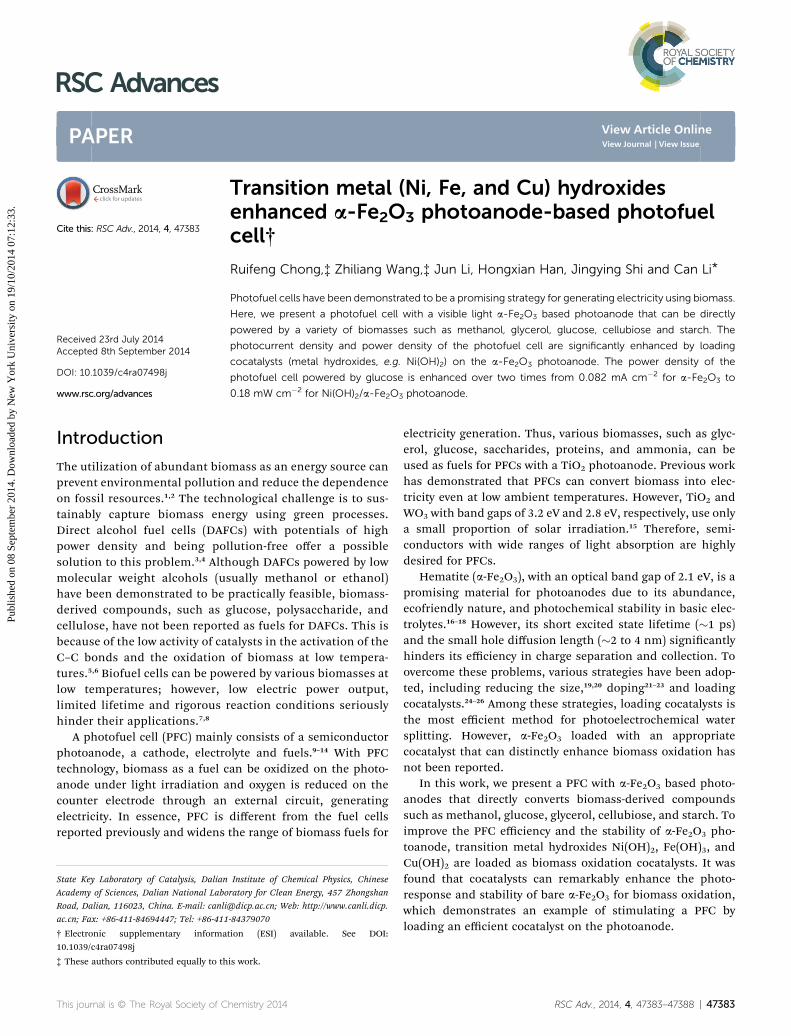
The XRD patterns of Fe2O3 lm are shown in Fig. 1a. Thesample shows diffraction peaks with 2q at 35.6�and 64.0�, whichcorrespond to the indices of the (110) and (300) planes (PDF no.840306) of hematite phase, respectively. The UV-visible spec-trum (Fig. 1b) gives the bands of a-Fe2O3 at 410 nm and around600 nm, which corresponds to the direct transition of O2� 2p/
Fe3+ 3d and the transition of the spin-forbidden Fe3+ 3d / 3d,respectively.28 Fig. 1c and d illustrate the top-view analysis andmorphology of a-Fe2O3 lm characterized by SEM. The lmconsists of a-Fe2O3 nanorod particles with a diameter of 20–30 nm and a length of 60–100 nm. The cross analysis of the lm
This journal is © The Royal Society of Chemistry 2014
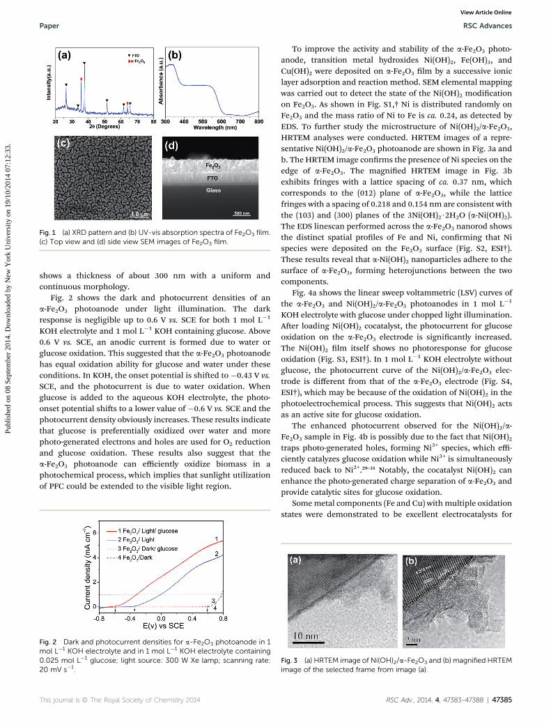
Fig. 1 (a) XRD pattern and (b) UV-vis absorption spectra of Fe2O3 film.(c) Top view and (d) side view SEM images of Fe2O3 film.
Paper RSC Advances
Publ
ishe
d on
08
Sept
embe
r 20
14. D
ownl
oade
d by
New
Yor
k U
nive
rsity
on
19/1
0/20
14 0
7:12
:33.
View Article Online
shows a thickness of about 300 nm with a uniform andcontinuous morphology.
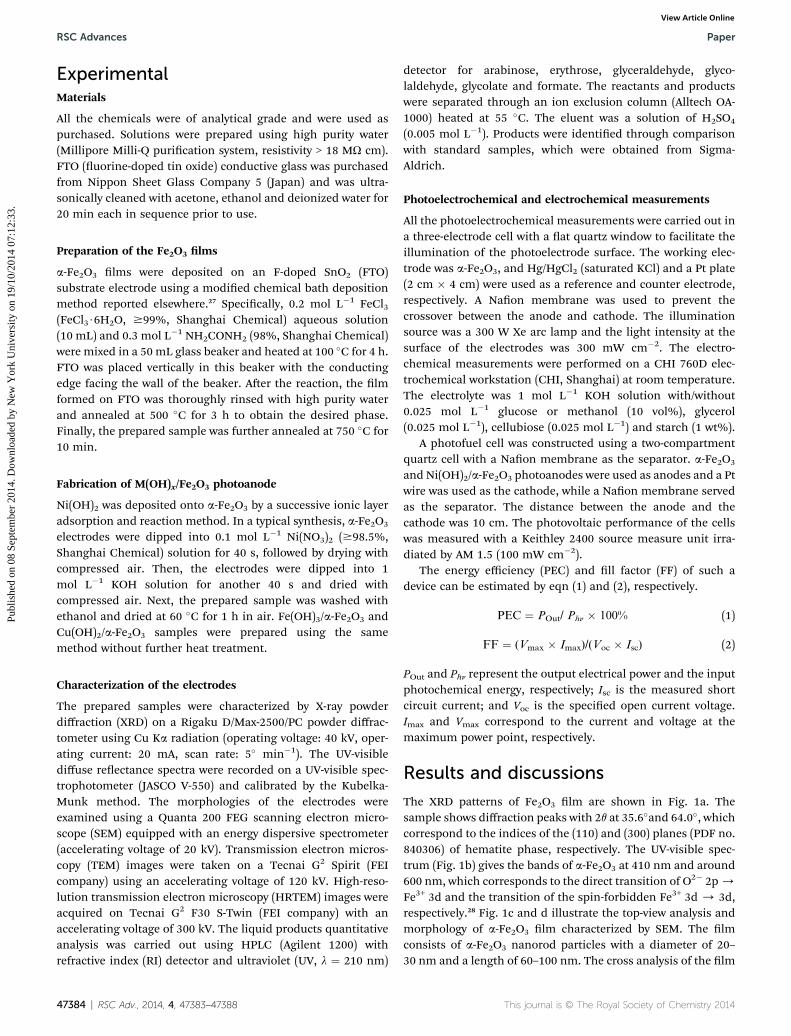
Fig. 2 shows the dark and photocurrent densities of ana-Fe2O3 photoanode under light illumination. The darkresponse is negligible up to 0.6 V vs. SCE for both 1 mol L�1
KOH electrolyte and 1 mol L�1 KOH containing glucose. Above0.6 V vs. SCE, an anodic current is formed due to water orglucose oxidation. This suggested that the a-Fe2O3 photoanodehas equal oxidation ability for glucose and water under theseconditions. In KOH, the onset potential is shied to �0.43 V vs.SCE, and the photocurrent is due to water oxidation. Whenglucose is added to the aqueous KOH electrolyte, the photo-onset potential shis to a lower value of �0.6 V vs. SCE and thephotocurrent density obviously increases. These results indicatethat glucose is preferentially oxidized over water and morephoto-generated electrons and holes are used for O2 reductionand glucose oxidation. These results also suggest that thea-Fe2O3 photoanode can efficiently oxidize biomass in aphotochemical process, which implies that sunlight utilizationof PFC could be extended to the visible light region.
Fig. 2 Dark and photocurrent densities for a-Fe2O3 photoanode in 1mol L�1 KOH electrolyte and in 1 mol L�1 KOH electrolyte containing0.025 mol L�1 glucose; light source: 300 W Xe lamp; scanning rate:20 mV s�1.
This journal is © The Royal Society of Chemistry 2014
To improve the activity and stability of the a-Fe2O3 photo-anode, transition metal hydroxides Ni(OH)2, Fe(OH)3, andCu(OH)2 were deposited on a-Fe2O3 lm by a successive ioniclayer adsorption and reaction method. SEM elemental mappingwas carried out to detect the state of the Ni(OH)2 modicationon Fe2O3. As shown in Fig. S1,† Ni is distributed randomly onFe2O3 and the mass ratio of Ni to Fe is ca. 0.24, as detected byEDS. To further study the microstructure of Ni(OH)2/a-Fe2O3,HRTEM analyses were conducted. HRTEM images of a repre-sentative Ni(OH)2/a-Fe2O3 photoanode are shown in Fig. 3a andb. The HRTEM image conrms the presence of Ni species on theedge of a-Fe2O3. The magnied HRTEM image in Fig. 3bexhibits fringes with a lattice spacing of ca. 0.37 nm, whichcorresponds to the (012) plane of a-Fe2O3, while the latticefringes with a spacing of 0.218 and 0.154 nm are consistent withthe (103) and (300) planes of the 3Ni(OH)2$2H2O (a-Ni(OH)2).The EDS linescan performed across the a-Fe2O3 nanorod showsthe distinct spatial proles of Fe and Ni, conrming that Nispecies were deposited on the Fe2O3 surface (Fig. S2, ESI†).These results reveal that a-Ni(OH)2 nanoparticles adhere to thesurface of a-Fe2O3, forming heterojunctions between the twocomponents.
Fig. 4a shows the linear sweep voltammetric (LSV) curves ofthe a-Fe2O3 and Ni(OH)2/a-Fe2O3 photoanodes in 1 mol L�1
KOH electrolyte with glucose under chopped light illumination.Aer loading Ni(OH)2 cocatalyst, the photocurrent for glucoseoxidation on the a-Fe2O3 electrode is signicantly increased.The Ni(OH)2 lm itself shows no photoresponse for glucoseoxidation (Fig. S3, ESI†). In 1 mol L�1 KOH electrolyte withoutglucose, the photocurrent curve of the Ni(OH)2/a-Fe2O3 elec-trode is different from that of the a-Fe2O3 electrode (Fig. S4,ESI†), which may be because of the oxidation of Ni(OH)2 in thephotoelectrochemical process. This suggests that Ni(OH)2 actsas an active site for glucose oxidation.
The enhanced photocurrent observed for the Ni(OH)2/a-Fe2O3 sample in Fig. 4b is possibly due to the fact that Ni(OH)2traps photo-generated holes, forming Ni3+ species, which effi-ciently catalyzes glucose oxidation while Ni3+ is simultaneouslyreduced back to Ni2+.29–31 Notably, the cocatalyst Ni(OH)2 canenhance the photo-generated charge separation of a-Fe2O3 andprovide catalytic sites for glucose oxidation.
Somemetal components (Fe and Cu) with multiple oxidationstates were demonstrated to be excellent electrocatalysts for
Fig. 3 (a) HRTEM image of Ni(OH)2/a-Fe2O3 and (b) magnified HRTEMimage of the selected frame from image (a).
RSC Adv., 2014, 4, 47383–47388 | 47385
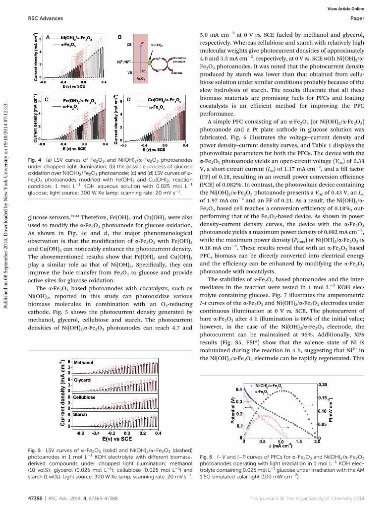
Fig. 4 (a) LSV curves of Fe2O3 and Ni(OH)2/a-Fe2O3 photoanodesunder chopped light illumination; (b) the possible process of glucoseoxidation over Ni(OH)2/Fe2O3 photoanode; (c) and (d) LSV curves of a-Fe2O3 photoanodes modified with Fe(OH)3 and Cu(OH)2; reactioncondition: 1 mol L�1 KOH aqueous solution with 0.025 mol L�1
glucose; light source: 300 W Xe lamp; scanning rate: 20 mV s�1.
RSC Advances Paper
Publ
ishe
d on
08
Sept
embe
r 20
14. D
ownl
oade
d by
New
Yor
k U
nive
rsity
on
19/1
0/20
14 0
7:12
:33.
View Article Online
glucose sensors.32,33 Therefore, Fe(OH)3 and Cu(OH)2 were alsoused to modify the a-Fe2O3 photoanode for glucose oxidation.As shown in Fig. 4c and d, the major phenomenologicalobservation is that the modication of a-Fe2O3 with Fe(OH)3and Cu(OH)2 can noticeably enhance the photocurrent density.The abovementioned results show that Fe(OH)3 and Cu(OH)2play a similar role as that of Ni(OH)2. Specically, they canimprove the hole transfer from Fe2O3 to glucose and provideactive sites for glucose oxidation.
The a-Fe2O3 based photoanodes with cocatalysts, such asNi(OH)2, reported in this study can photooxidize variousbiomass molecules in combination with an O2-reducingcathode. Fig. 5 shows the photocurrent density generated bymethanol, glycerol, cellubiose and starch. The photocurrentdensities of Ni(OH)2/a-Fe2O3 photoanodes can reach 4.7 and
Fig. 5 LSV curves of a-Fe2O3 (solid) and Ni(OH)2/a-Fe2O3 (dashed)photoanodes in 1 mol L�1 KOH electrolyte with different biomass-derived compounds under chopped light illumination; methanol(10 vol%); glycerol (0.025 mol L�1); cellubiose (0.025 mol L�1) andstarch (1 wt%). Light source: 300 W Xe lamp; scanning rate: 20 mV s�1.
47386 | RSC Adv., 2014, 4, 47383–47388
5.0 mA cm�2 at 0 V vs. SCE fueled by methanol and glycerol,respectively. Whereas cellubiose and starch with relatively highmolecular weights give photocurrent densities of approximately4.0 and 3.5 mA cm�2, respectively, at 0 V vs. SCE with Ni(OH)2/a-Fe2O3 photoanodes. It was noted that the photocurrent densityproduced by starch was lower than that obtained from cellu-biose solution under similar conditions probably because of theslow hydrolysis of starch. The results illustrate that all thesebiomass materials are promising fuels for PFCs and loadingcocatalysts is an efficient method for improving the PFCperformance.
A simple PFC consisting of an a-Fe2O3 (or Ni(OH)2/a-Fe2O3)photoanode and a Pt plate cathode in glucose solution wasfabricated. Fig. 6 illustrates the voltage–current density andpower density–current density curves, and Table 1 displays thephotovoltaic parameters for both the PFCs. The device with thea-Fe2O3 photoanode yields an open-circuit voltage (Voc) of 0.38V, a short-circuit current (Isc) of 1.17 mA cm�2, and a ll factor(FF) of 0.18, resulting in an overall power conversion efficiency(PCE) of 0.082%. In contrast, the photovoltaic device containingthe Ni(OH)2/a-Fe2O3 photoanode presents a Voc of 0.43 V, an Iscof 1.97 mA cm�2 and an FF of 0.21. As a result, the Ni(OH)2/a-Fe2O3 based cell reaches a conversion efficiency of 0.18%, out-performing that of the Fe2O3-based device. As shown in powerdensity–current density curves, the device with the a-Fe2O3
photoanode yields amaximum power density of 0.082mA cm�2,while the maximum power density (Pmax) of Ni(OH)2/a-Fe2O3 is0.18 mA cm�2. These results reveal that with an a-Fe2O3 basedPFC, biomass can be directly converted into electrical energyand the efficiency can be enhanced by modifying the a-Fe2O3
photoanode with cocatalysts.The stabilities of a-Fe2O3 based photoanodes and the inter-
mediates in the reaction were tested in 1 mol L�1 KOH elec-trolyte containing glucose. Fig. 7 illustrates the amperometricI–t curves of the a-Fe2O3 and Ni(OH)2/a-Fe2O3 electrodes undercontinuous illumination at 0 V vs. SCE. The photocurrent ofbare a-Fe2O3 aer 4 h illumination is 86% of the initial value;however, in the case of the Ni(OH)2/a-Fe2O3 electrode, thephotocurrent can be maintained at 96%. Additionally, XPSresults (Fig. S5, ESI†) show that the valence state of Ni ismaintained during the reaction in 4 h, suggesting that Ni2+ inthe Ni(OH)2/a-Fe2O3 electrode can be rapidly regenerated. This
Fig. 6 I–V and I–P curves of PFCs for a-Fe2O3 and Ni(OH)2/a-Fe2O3
photoanodes operating with light irradiation in 1 mol L�1 KOH elec-trolyte containing 0.025 mol L�1 glucose under irradiation with the AM1.5G simulated solar light (100 mW cm�2).
This journal is © The Royal Society of Chemistry 2014
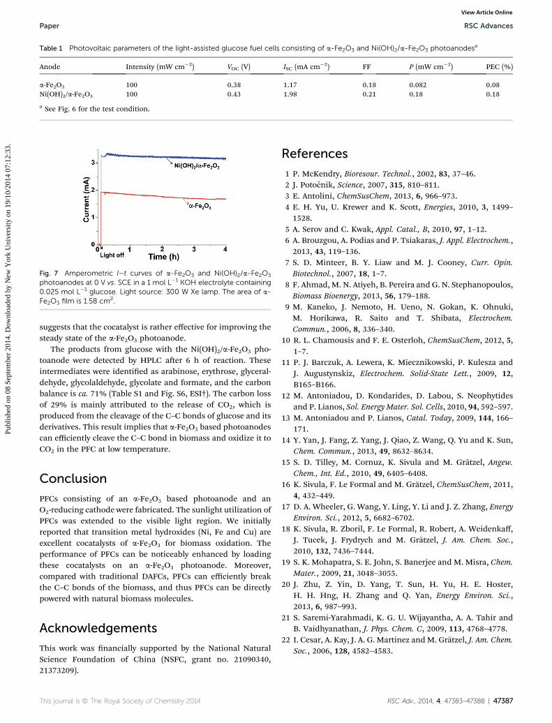
Fig. 7 Amperometric I–t curves of a-Fe2O3 and Ni(OH)2/a-Fe2O3
photoanodes at 0 V vs. SCE in a 1 mol L�1 KOH electrolyte containing0.025 mol L�1 glucose. Light source: 300 W Xe lamp. The area of a-Fe2O3 film is 1.58 cm2.
Table 1 Photovoltaic parameters of the light-assisted glucose fuel cells consisting of a-Fe2O3 and Ni(OH)2/a-Fe2O3 photoanodesa
Anode Intensity (mW cm�2) VOC (V) ISC (mA cm�2) FF P (mW cm�2) PEC (%)
a-Fe2O3 100 0.38 1.17 0.18 0.082 0.08Ni(OH)2/a-Fe2O3 100 0.43 1.98 0.21 0.18 0.18
a See Fig. 6 for the test condition.
Paper RSC Advances
Publ
ishe
d on
08
Sept
embe
r 20
14. D
ownl
oade
d by
New
Yor
k U
nive
rsity
on
19/1
0/20
14 0
7:12
:33.
View Article Online
suggests that the cocatalyst is rather effective for improving thesteady state of the a-Fe2O3 photoanode.
The products from glucose with the Ni(OH)2/a-Fe2O3 pho-toanode were detected by HPLC aer 6 h of reaction. Theseintermediates were identied as arabinose, erythrose, glyceral-dehyde, glycolaldehyde, glycolate and formate, and the carbonbalance is ca. 71% (Table S1 and Fig. S6, ESI†). The carbon lossof 29% is mainly attributed to the release of CO2, which isproduced from the cleavage of the C–C bonds of glucose and itsderivatives. This result implies that a-Fe2O3 based photoanodescan efficiently cleave the C–C bond in biomass and oxidize it toCO2 in the PFC at low temperature.
Conclusion
PFCs consisting of an a-Fe2O3 based photoanode and anO2-reducing cathode were fabricated. The sunlight utilization ofPFCs was extended to the visible light region. We initiallyreported that transition metal hydroxides (Ni, Fe and Cu) areexcellent cocatalysts of a-Fe2O3 for biomass oxidation. Theperformance of PFCs can be noticeably enhanced by loadingthese cocatalysts on an a-Fe2O3 photoanode. Moreover,compared with traditional DAFCs, PFCs can efficiently breakthe C–C bonds of the biomass, and thus PFCs can be directlypowered with natural biomass molecules.
Acknowledgements
This work was nancially supported by the National NaturalScience Foundation of China (NSFC, grant no. 21090340,21373209).
This journal is © The Royal Society of Chemistry 2014
References
1 P. McKendry, Bioresour. Technol., 2002, 83, 37–46.2 J. Potocnik, Science, 2007, 315, 810–811.3 E. Antolini, ChemSusChem, 2013, 6, 966–973.4 E. H. Yu, U. Krewer and K. Scott, Energies, 2010, 3, 1499–1528.
5 A. Serov and C. Kwak, Appl. Catal., B, 2010, 97, 1–12.6 A. Brouzgou, A. Podias and P. Tsiakaras, J. Appl. Electrochem.,2013, 43, 119–136.
7 S. D. Minteer, B. Y. Liaw and M. J. Cooney, Curr. Opin.Biotechnol., 2007, 18, 1–7.
8 F. Ahmad, M. N. Atiyeh, B. Pereira and G. N. Stephanopoulos,Biomass Bioenergy, 2013, 56, 179–188.
9 M. Kaneko, J. Nemoto, H. Ueno, N. Gokan, K. Ohnuki,M. Horikawa, R. Saito and T. Shibata, Electrochem.Commun., 2006, 8, 336–340.
10 R. L. Chamousis and F. E. Osterloh, ChemSusChem, 2012, 5,1–7.
11 P. J. Barczuk, A. Lewera, K. Miecznikowski, P. Kulesza andJ. Augustynskiz, Electrochem. Solid-State Lett., 2009, 12,B165–B166.
12 M. Antoniadou, D. Kondarides, D. Labou, S. Neophytidesand P. Lianos, Sol. Energy Mater. Sol. Cells, 2010, 94, 592–597.
13 M. Antoniadou and P. Lianos, Catal. Today, 2009, 144, 166–171.
14 Y. Yan, J. Fang, Z. Yang, J. Qiao, Z. Wang, Q. Yu and K. Sun,Chem. Commun., 2013, 49, 8632–8634.
15 S. D. Tilley, M. Cornuz, K. Sivula and M. Gratzel, Angew.Chem., Int. Ed., 2010, 49, 6405–6408.
16 K. Sivula, F. Le Formal and M. Gratzel, ChemSusChem, 2011,4, 432–449.
17 D. A. Wheeler, G. Wang, Y. Ling, Y. Li and J. Z. Zhang, EnergyEnviron. Sci., 2012, 5, 6682–6702.
18 K. Sivula, R. Zboril, F. Le Formal, R. Robert, A. Weidenkaff,J. Tucek, J. Frydrych and M. Gratzel, J. Am. Chem. Soc.,2010, 132, 7436–7444.
19 S. K. Mohapatra, S. E. John, S. Banerjee and M. Misra, Chem.Mater., 2009, 21, 3048–3055.
20 J. Zhu, Z. Yin, D. Yang, T. Sun, H. Yu, H. E. Hoster,H. H. Hng, H. Zhang and Q. Yan, Energy Environ. Sci.,2013, 6, 987–993.
21 S. Saremi-Yarahmadi, K. G. U. Wijayantha, A. A. Tahir andB. Vaidhyanathan, J. Phys. Chem. C, 2009, 113, 4768–4778.
22 I. Cesar, A. Kay, J. A. G. Martinez andM. Gratzel, J. Am. Chem.Soc., 2006, 128, 4582–4583.
RSC Adv., 2014, 4, 47383–47388 | 47387

RSC Advances Paper
Publ
ishe
d on
08
Sept
embe
r 20
14. D
ownl
oade
d by
New
Yor
k U
nive
rsity
on
19/1
0/20
14 0
7:12
:33.
View Article Online
23 Y. Hu, A. Kleiman-Shwarsctein, A. J. Forman, D. Hazen,J. Park and E. W. McFarland, Chem. Mater., 2008, 20, 3803–3805.
24 S. D. Tilley, M. Cornuz, K. Sivula and M. Gratzel, Angew.Chem., Int. Ed., 2010, 49, 6405–6408.
25 I. Cesar, A. Kay, J. A. G. Martinez andM. Gratzel, J. Am. Chem.Soc., 2006, 128, 4582–4583.
26 J. Y. Kim, G. Magesh, D. H. Youn, J. Jang, J. Kubota,K. Domen and J. S. Lee, Sci. Rep., 2013, 3, 2681.
27 H. K. Mulmudi, N. Mathews, X. C. Dou, L. F. Xi,S. S. Pramana, Y. M. Lam and S. G. Mhaisalker,Electrochem. Commun., 2011, 13, 951–954.
47388 | RSC Adv., 2014, 4, 47383–47388
28 L. Armelao, R. Bartoncello, L. Crociani, G. Depaoli,G. Granozzi, E. Tondello and M. Benttinelli, J. Mater.Chem., 1995, 5, 79–83.
29 P. R. Martins, M. A. Rocha, L. Angnes, H. E. Toma andK. Araki, Electroanalysis, 2011, 23, 2541–2548.
30 J. Nai, S. Wang, Y. Bai and L. Guo, Small, 2013, 9, 3147–3152.31 S. Xie, T. Zhai, W. Li, M. Yu, C. Liang, J. Gan, X. Lu and
Y. Tong, Green Chem., 2013, 15, 2434–2440.32 X. Cao and N. Wang, Analyst, 2011, 136, 4241–4246.33 S. Sun, X. Zhang, Y. Sun, S. Yang, X. Song and Z. Yang, ACS
Appl. Mater. Interfaces, 2013, 5, 4429–4437.
This journal is © The Royal Society of Chemistry 2014


![Microstructure,Mossbauer,andOpticalCharacterizationsof ...downloads.hindawi.com/journals/isrn/2011/406094.pdf · mal[13],chemicalvapor phasedeposition [14],calcinations of hydroxides](https://img.pdfslide.tips/doc/110x75/5f7840b9ab2f312c2f7c1798/microstructuremossbauerandopticalcharacterizationsof-mal13chemicalvapor.jpg)