Embed Size (px)
Citation preview
TREBALL FINAL DE GRAU
TÍTOL DEL TFG: Autonomous Rover for Indoor Localization TITULACIÓ: Grau en Enginyeria d’Aeronavegació AUTOR: Novak Vukmirica Pastor DIRECTOR: Enric Fernández Murcia SUPERVISOR: David Pino González DATA: 22 de Maig del 2017

Títol: Autonomous Rover for Indoor Localization Autor: Novak Vukmirica Pastor Director: Enric Fernández Murcia Data: 22 de Maig del 2017
Resum
L'objectiu principal del treball ha sigut la implementació d'un sistema de localització d’un Rover per a interiors, processant dades provinents d’una sèrie de sensors integrats en el sistema operatiu ROS (Robotic Operating System). ROS s'ha seleccionat a causa del seu potencial i creixement dintre de la indústria de la robòtica. El projecte inclou una plataforma de treball, en aquest cas un Rover que incorpora els diferents sensors utilitzats (odòmetres i sensors inercials). Cal remarcar que l'estructura del Rover, les rodes i els motors han estat comprats conjuntament (kit), i s’han hagut de muntar seguint el manual del fabricant. L’adquisició de les dades dels sensors es realitza mitjançant dos microcontroladors (Arduino i Motor Controller). Posteriorment, aquestes dades són enviades a través d'un port sèrie al microprocessador principal (Raspberry Pi model 3) on s’executa ROS. Per tant, els missatges que rep ROS s’han d’adaptar al format necessari perquè puguin ser correctament interpretats. La sortida estimada del sistema ROS és el TPVA (Time, Position, Velocity and Attitude) del Rover (estant preparada per utilitzar juntament amb altres mòduls de ROS). S'han dissenyat, implementat i validat uns procediments de calibratge per als sensors inercials (acceleròmetres i giroscopis). Generalment, el sistema es farà servir en interiors. S'ha treballat sota un marc de referència local, però tenint en compte futures adaptacions a marcs de referència globals, sent part de la feina realitzada la familiarització de les transformacions de coordenades i temps.

Title: Autonomous Rover for Indoor Localization
Autor: Novak Vukmirica Pastor
Director: Enric Fernández Murcia
Date: May 22nd 2017
Overview
The goal of this project is the implementation of an indoor Rover localization system, processing data from a set of sensors integrated in the ROS (Robotic Operative System) system. ROS is selected due its modularity and broad use in the robotics field. The project includes a work platform, in our case a Rover where have to be implemented the different sensors (odometers and inertial sensors). It has to be noted that the Rover structure, the wheels and motors have been bought together (kit), and has been assembled using an assembly user guide. Sensor data have been acquired through two microcontrollers (Arduino and Motor Controller). Then, this data is sent through a serial port to the main microprocessors (Raspberry Pi 3) where ROS is executed. Hence, ROS reception messages have to be properly adapted to the format desired. The estimated output of ROS is the position and attitude of the Rover (being prepared to use along with other ROS modules). Calibration procedures must be designed, implemented and validated, for all or some of the sensors. The system will be used mainly in indoors (i.e. buildings). It must work with local and global reference systems. Hence, I have had to achieve some familiarity with coordinate and time transformations.

GUIDELINES
CHAPTER 1. INTRODUCTION .............................................................................. 1
1.1. Project Scope ................................................................................................. 1
1.2. Goals .............................................................................................................. 1
1.3. Document Overview ....................................................................................... 2
CHAPTER 2. STATE OF THE ART ........................................................................ 3
CHAPTER 3. SYSTEM ARCHITECTURE .............................................................. 7
3.1. Overview ........................................................................................................ 7
3.2. System Requirements .................................................................................... 8
3.3. Hardware architecture .................................................................................... 8
3.4. Software architecture ...................................................................................... 9
CHAPTER 4. DETAILED SYSTEM DESIGN ........................................................ 11
4.1. Arduino Due.................................................................................................. 11
4.2. Raspberry Pi 3 Model B ................................................................................ 13
4.3. Motor Controller (Pololu 2x15A) .................................................................... 15
4.3.1. Motors and Encoders ................................................................................ 17
4.4. IMU ............................................................................................................... 18
4.5. Communication Interfaces ............................................................................ 19
4.5.1. Serial Port .............................................................................................. 19
4.5.2. SPI ........................................................................................................ 20
4.6. Power feeding ............................................................................................... 22
CHAPTER 5. ROS ............................................................................................... 25
5.1. ENVIRONMENT SETUP .............................................................................. 25
5.1.1. YAML configuration file .......................................................................... 26
5.2. MOST USED TERMINAL COMMANDS ....................................................... 27
5.3. PUBLISHERS AND SUBSCRIBERS ............................................................ 27
5.3.1. rosserial_arduino: /imu topic .................................................................. 28
5.3.2. rosserial_arduino: /odom topic ............................................................... 29
5.3.3. robot_localization: /odometry/filtered topic ............................................. 29
5.4. EXECUTING ROS ........................................................................................ 31
CHAPTER 6. TESTING & VALIDATION............................................................... 33
6.1. Forward Maneuver Test ................................................................................ 34
6.2. Forward-Backward Maneuver Test ............................................................... 36
6.3. Turn Maneuver Test ..................................................................................... 38
CHAPTER 7. CONCLUSIONS ............................................................................. 41
BIBLIOGRAPHY ......................................................................................................... 43
APPENDIX A .............................................................................................................. 48
APPENDIX B .............................................................................................................. 63
APPENDIX C .............................................................................................................. 65
LIST OF FIGURES
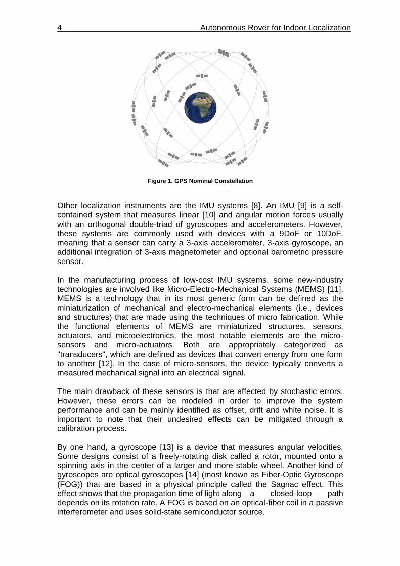
Figure 1. GPS Nominal Constellation ................................................................. 4
Figure 2. Rover Curiosity .................................................................................... 6 Figure 3. Lynxmotion Aluminium A4WD1 Rover Kit ........................................... 7 Figure 4. Hardware architecture overview .......................................................... 8 Figure 5. Raspberry flux diagram ....................................................................... 9 Figure 6. Arduino flux diagram ......................................................................... 10
Figure 7. Micro-controller (Arduino Due) pinout and physical board diagram ... 12 Figure 8. Raspberry Pi 3 Model B illustration ................................................... 14
Figure 9. Micro-processor (Raspberry Pi 3 Model B) pinout ............................. 14 Figure 10. Motor Controller (Pololu 2x15A) pinout ........................................... 15 Figure 11. Motor Controller (Pololu 2x15A) basic wiring .................................. 16 Figure 12. Encoder (QME-01) .......................................................................... 17 Figure 13. IMU (MPU-9250) UEVB .................................................................. 19
Figure 14. SPI bus: 1 Master & 3 Slaves .......................................................... 20 Figure 15. Timing diagram showing clock polarity and phase .......................... 21 Figure 16. Power Feeding and interface connections of the system ................ 22 Figure 17. Basic scheme of modules (nodes and topics) ................................. 28
Figure 18. Forward Maneuver path .................................................................. 34 Figure 19. Forward-Backward Maneuver path ................................................. 36
Figure 20. Turn Maneuver path ........................................................................ 38
LIST OF TABLES
Table 1. Technical Specs of Arduino Due ........................................................ 11
Table 2. Technical Specs of Raspberry Pi 3 B ................................................. 13 Table 3. Technical Specs of Motor Controller................................................... 15 Table 4. Technical Specs of Motors GHM-04 ................................................... 17
Table 5. Technical Specs of Encoders QME-01 ............................................... 17 Table 6. Technical Specs of MPU-9250 ........................................................... 18
Table 7. TEN 60-1212N power specifications .................................................. 23
Table 8. picoPSU-150-XT DC/DC .................................................................... 23 Table 9. Consumption table (DC) ..................................................................... 23 Table 10. Results from Forward Maneuver Test .............................................. 35
Table 11. Standard deviation (in meters) from Forward Maneuver test ............ 35 Table 12. Results from Forward-Backward Maneuver Test ............................. 37 Table 13. Standard deviation (in meters) from Forward-Backward Maneuver test ......................................................................................................................... 37 Table 14. Results from Turn Maneuver test ..................................................... 38
Table 15. Standard deviation (in meters) from Turn Maneuver test ................. 39
INTRODUCTION 1
CHAPTER 1. INTRODUCTION
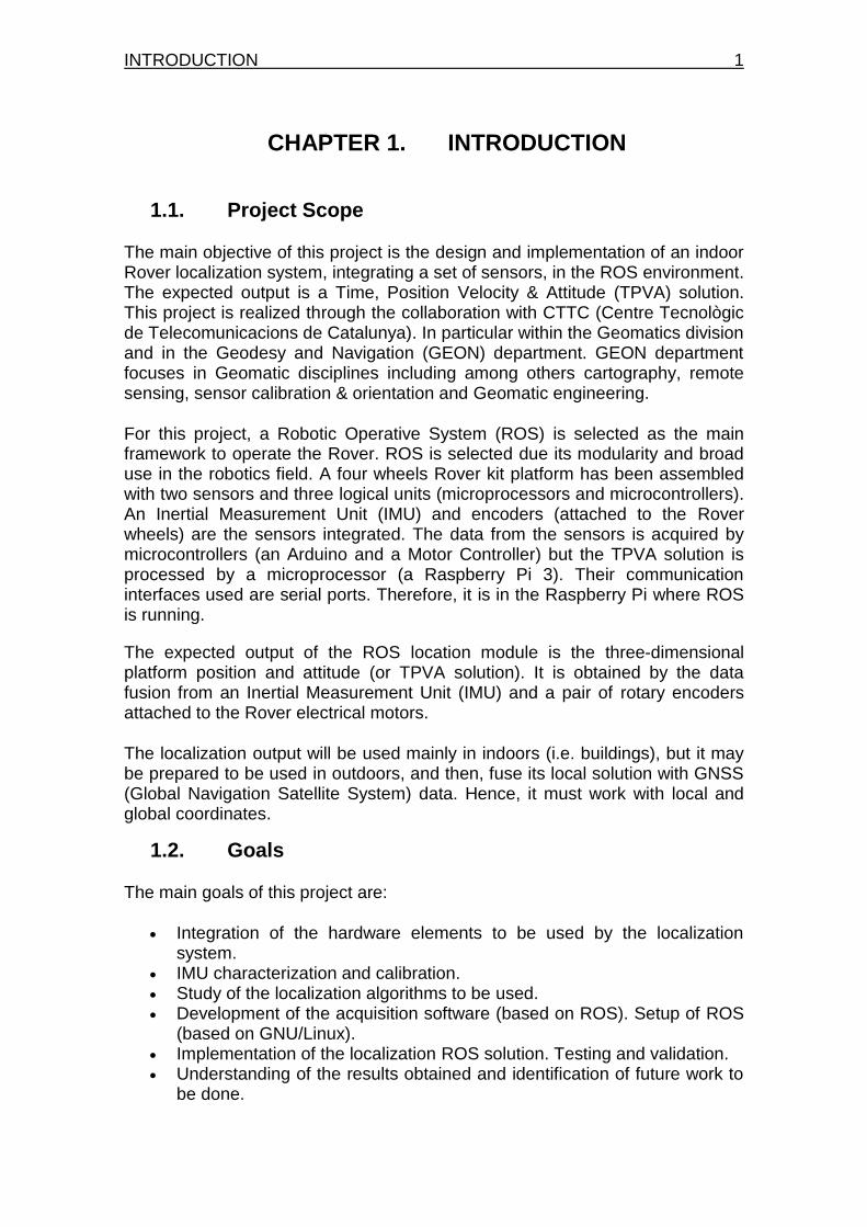
1.1. Project Scope
The main objective of this project is the design and implementation of an indoor Rover localization system, integrating a set of sensors, in the ROS environment. The expected output is a Time, Position Velocity & Attitude (TPVA) solution. This project is realized through the collaboration with CTTC (Centre Tecnològic de Telecomunicacions de Catalunya). In particular within the Geomatics division and in the Geodesy and Navigation (GEON) department. GEON department focuses in Geomatic disciplines including among others cartography, remote sensing, sensor calibration & orientation and Geomatic engineering.
For this project, a Robotic Operative System (ROS) is selected as the main framework to operate the Rover. ROS is selected due its modularity and broad use in the robotics field. A four wheels Rover kit platform has been assembled with two sensors and three logical units (microprocessors and microcontrollers). An Inertial Measurement Unit (IMU) and encoders (attached to the Rover wheels) are the sensors integrated. The data from the sensors is acquired by microcontrollers (an Arduino and a Motor Controller) but the TPVA solution is processed by a microprocessor (a Raspberry Pi 3). Their communication interfaces used are serial ports. Therefore, it is in the Raspberry Pi where ROS is running.
The expected output of the ROS location module is the three-dimensional platform position and attitude (or TPVA solution). It is obtained by the data fusion from an Inertial Measurement Unit (IMU) and a pair of rotary encoders attached to the Rover electrical motors.
The localization output will be used mainly in indoors (i.e. buildings), but it may be prepared to be used in outdoors, and then, fuse its local solution with GNSS (Global Navigation Satellite System) data. Hence, it must work with local and global coordinates.
1.2. Goals
The main goals of this project are:
Integration of the hardware elements to be used by the localization system.
IMU characterization and calibration. Study of the localization algorithms to be used. Development of the acquisition software (based on ROS). Setup of ROS
(based on GNU/Linux). Implementation of the localization ROS solution. Testing and validation. Understanding of the results obtained and identification of future work to
be done.
2 Autonomous Rover for Indoor Localization
1.3. Document Overview
This document presents the design, implementation and validation of an autonomous indoor localization system in a Rover platform. The chapters are organized taking into account the different work blocks of the proposed system. Chapter 2 explores the state of the art of the current localization systems and the evolution of the most known Rover platforms and their applications. It is also focused on presenting current techniques and procedures for obtaining an estimated localization using a low-cost inertial sensor and rotary encoders. Chapter 3 presents the main system architecture of the project, the system requirements and some schemes about the main elements used to develop this project. Chapter 4 defines detailed system designs, taking into account hardware (HW) and software (SW) platforms. It is explained in detail the conceptual design of the autonomous Rover for indoor localization. Chapter 5 explains what is ROS, how to setup its environment and its main modules and execution commands. Chapter 6 contains all tests carried out to validate the TPVA solution. Detailed description and analysis of results are included, such as path diagrams to understand motion patterns executed. Chapter 7 summarizes the conclusions highlights and offers some outlook ideas and proposals to continue the work started within this project.
STATE OF THE ART 3
CHAPTER 2. STATE OF THE ART
The necessity to locate everything, in a local or global reference frame, is inherent to the human condition and its constant displacements, mainly for migratory or commercial purposes. An example is the ancient marine navigation for the exploration and colonization of new places by ancient civilizations such as Greeks and Phoenicians. Formerly, some of the first reference systems to determinate a location (or a direction) were the Sun, during the day, and the stars at night. These elements guided the ancient tribes to colonize the entire Earth. The computations made to locate places, at least locally, were mainly based in trigonometry. But as the times goes by, the instruments used for location evolved; from first millennial "Astrolabe", a popular instrument for marine navigation, to more recent Global Positioning System (GPS) systems [1]. The GPS was developed by the U.S. government in the earlies 60s. It is a radio navigation system that helps pinpoint a three dimensional position (i.e. latitude, longitude and altitude) typically to about a decameter of accuracy and provide Nano-second precise time anywhere on Earth outdoors (in a global reference frame). GPS system began in 1965, first known as TRANSIT [2], and it consisted in a 6-satellite constellation low-polar orbit, which fulfill global coverage but not constant (time-gaps). Next, in December of 1983 a new system called NAVSTAR [3] was developed, which consisted in a 24-satellite constellation medium-polar orbit, able to carry out a constant global coverage. The U.S. government is committed to maintaining the availability of at least 24 operational satellites, 95% of the time. To ensure this commitment, the Air Force has been flying 31 operational GPS satellites for the past few years. The GPS satellites provide service to civilian and military users. GPS system is included among the Global Navigation Satellite System (GNSS) [4], in which there are found GLONASS (Russia) [5], Beidou (China) [6] and Galileo (EU) [7] among others. Hence, GNSS are a set of technologies of satellite navigation systems which provide geo-spatial positioning with global autonomous coverage. Other localization instruments are the IMU systems [8] that are affected by stochastic errors. However, these errors can be modeled in order to improve the system performance and can be mainly identified as offset, drift and white noise. It is important to note that their undesired effects can be mitigated through a calibration process.
4 Autonomous Rover for Indoor Localization
Figure 1. GPS Nominal Constellation
Other localization instruments are the IMU systems [8]. An IMU [9] is a self-contained system that measures linear [10] and angular motion forces usually with an orthogonal double-triad of gyroscopes and accelerometers. However, these systems are commonly used with devices with a 9DoF or 10DoF, meaning that a sensor can carry a 3-axis accelerometer, 3-axis gyroscope, an additional integration of 3-axis magnetometer and optional barometric pressure sensor. In the manufacturing process of low-cost IMU systems, some new-industry technologies are involved like Micro-Electro-Mechanical Systems (MEMS) [11]. MEMS is a technology that in its most generic form can be defined as the miniaturization of mechanical and electro-mechanical elements (i.e., devices and structures) that are made using the techniques of micro fabrication. While the functional elements of MEMS are miniaturized structures, sensors, actuators, and microelectronics, the most notable elements are the micro-sensors and micro-actuators. Both are appropriately categorized as "transducers", which are defined as devices that convert energy from one form to another [12]. In the case of micro-sensors, the device typically converts a measured mechanical signal into an electrical signal. The main drawback of these sensors is that are affected by stochastic errors. However, these errors can be modeled in order to improve the system performance and can be mainly identified as offset, drift and white noise. It is important to note that their undesired effects can be mitigated through a calibration process. By one hand, a gyroscope [13] is a device that measures angular velocities. Some designs consist of a freely-rotating disk called a rotor, mounted onto a spinning axis in the center of a larger and more stable wheel. Another kind of gyroscopes are optical gyroscopes [14] (most known as Fiber-Optic Gyroscope (FOG)) that are based in a physical principle called the Sagnac effect. This effect shows that the propagation time of light along a closed-loop path depends on its rotation rate. A FOG is based on an optical-fiber coil in a passive interferometer and uses solid-state semiconductor source.
STATE OF THE ART 5
A triple axis gyroscope, can measure rotation around x, y and z axis. Some gyros come in single and dual axis varieties, but the triple axis gyro in a single chip is becoming more popular. By the other hand, an accelerometer is an electromechanical device used to measure acceleration forces. Such forces may be static, like the continuous force of gravity or vibrations. In a static situation, an accelerometer perpendicular to the Earth’s surface will measure Earth’s gravity. To measure travelled distance in a wheel-based vehicle, an odometer [15] is usually used. It is worth to mention that an odometer is considered as the multiplication of rotary encoder data by a wheel diameter factor, resulting in a distance measurement instead of angle or steps measurement device. Hence, its technology consists in a simple device that indicates distance travelled by a vehicle. The device may be electronic, mechanical or a combination of both. Generally, its technology consists in a wheel anchored to a calibrated gear, and could be independent or being integrated in a vehicle; counting the revolutions made by the wheel the distance travelled can be calculated in an easy way once the wheel’s radius is known. All the previously mentioned systems are commonly found on Rover platforms. A Rover is a space exploration vehicle designed to move across a planet surface or any other celestial body. Rovers are created to land on another planet, beside the Earth, for example to find out information and to take samples. Some Rovers have been designed to transport members of a human spaceflight; others have been partially or fully autonomous robots. In our case, the selected platform is a small-size Rover for indoor applications on the Earth. Referring to most known Rovers in the history [16], beginning with the Lunokhod (No.201), Soviet Rover was intended to be the first roving remote-controlled robot on the Moon, but crashed during a failed start of the launcher in February of 1969. The Lunokhod 1 was the first roving remote-controlled robot to land on a celestial body. Later, NASA included Lunar Roving Vehicles in three Apollo missions in the 70s. After that, a few Rovers as Prop-M Rover, Lunokhod 3, Marsokhod, Sojourner, Beagle 2 Planetary Undersurface Tool, Spirit, Chang'e 3 were developed and launched (both on the Moon and on Mars) until recent Rover missions like Opportunity and Curiosity. For instance, different Rover missions are being currently designed and tested like Mars 2020 Rover Mission [17], a NASA's Mars planetary Rover-mission concept which is intended to conduct geological assessments of its landing site on Mars, determine the habitability of the environment and search for signs of ancient Martian life. Many innovations [18] focus on entry, descent, and landing technologies, which help ensure precise and safe landings. They include sensors to measure the atmosphere, cameras and a microphone, and at least two key ways to reach the surface of Mars with greater accuracy and less risk (Range Trigger and Terrain-Relative Navigation). These Rovers depend on reliable operative system able to manage all information obtained from the different sensors and process it. Hence, the selection of the O.S. is critical to maximize the Rover capabilities. In Rover
6 Autonomous Rover for Indoor Localization
platforms, it is usual to rely on Real-Time Operative Systems (RTOS), which is an operating system intended to serve real-time applications which process data as it comes in, typically, without buffering delays. However, a little less know alternative [19] is "event-driven" software structure based on an event-driven framework and encapsulated state machines. Virtually all commercially successful design automation tools on the market today (Telelogic Rhapsody, Rose Real-Time...) are based on hierarchical state machines and incorporate internally a variant of an event-driven framework.
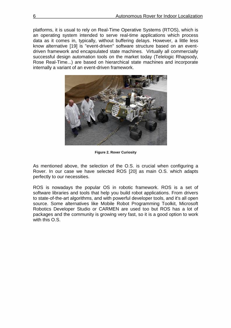
Figure 2. Rover Curiosity
As mentioned above, the selection of the O.S. is crucial when configuring a Rover. In our case we have selected ROS [20] as main O.S. which adapts perfectly to our necessities. ROS is nowadays the popular OS in robotic framework. ROS is a set of software libraries and tools that help you build robot applications. From drivers to state-of-the-art algorithms, and with powerful developer tools, and it's all open source. Some alternatives like Mobile Robot Programming Toolkit, Microsoft Robotics Developer Studio or CARMEN are used too but ROS has a lot of packages and the community is growing very fast, so it is a good option to work with this O.S.
SYSTEM ARCHITECTURE 7
CHAPTER 3. SYSTEM ARCHITECTURE
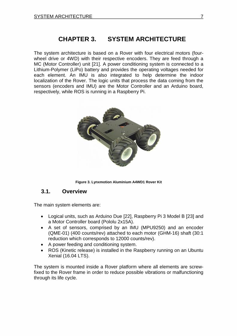
The system architecture is based on a Rover with four electrical motors (four-wheel drive or 4WD) with their respective encoders. They are feed through a MC (Motor Controller) unit [21]. A power conditioning system is connected to a Lithium-Polymer (LiPo) battery and provides the operating voltages needed for each element. An IMU is also integrated to help determine the indoor localization of the Rover. The logic units that process the data coming from the sensors (encoders and IMU) are the Motor Controller and an Arduino board, respectively, while ROS is running in a Raspberry Pi.
Figure 3. Lynxmotion Aluminium A4WD1 Rover Kit
3.1. Overview
The main system elements are:
Logical units, such as Arduino Due [22], Raspberry Pi 3 Model B [23] and a Motor Controller board (Pololu 2x15A).
A set of sensors, comprised by an IMU (MPU9250) and an encoder (QME-01) (400 counts/rev) attached to each motor (GHM-16) shaft (30:1 reduction which corresponds to 12000 counts/rev).
A power feeding and conditioning system.
ROS (Kinetic release) is installed in the Raspberry running on an Ubuntu Xenial (16.04 LTS).
The system is mounted inside a Rover platform where all elements are screw-fixed to the Rover frame in order to reduce possible vibrations or malfunctioning through its life cycle.
8 Autonomous Rover for Indoor Localization
3.2. System Requirements
The following system requirements, defined by the CTTC, have been the starting point of this project:
Correct assembly of the Rover platform kit.
IMU modeling and calibration.
ROS localization environment setup, verification and validation.
3.3. Hardware architecture
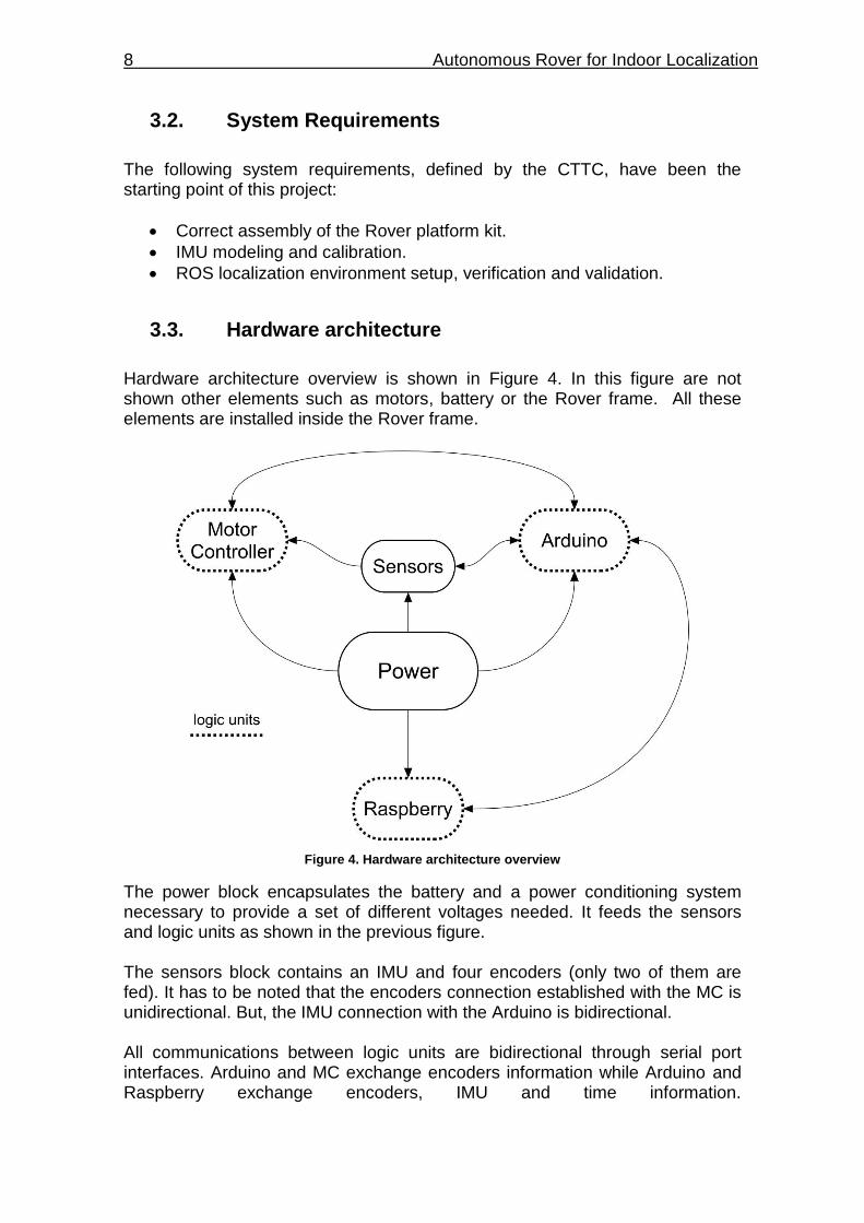
Hardware architecture overview is shown in Figure 4. In this figure are not shown other elements such as motors, battery or the Rover frame. All these elements are installed inside the Rover frame.
Figure 4. Hardware architecture overview
The power block encapsulates the battery and a power conditioning system necessary to provide a set of different voltages needed. It feeds the sensors and logic units as shown in the previous figure. The sensors block contains an IMU and four encoders (only two of them are fed). It has to be noted that the encoders connection established with the MC is unidirectional. But, the IMU connection with the Arduino is bidirectional. All communications between logic units are bidirectional through serial port interfaces. Arduino and MC exchange encoders information while Arduino and Raspberry exchange encoders, IMU and time information.
SYSTEM ARCHITECTURE 9
3.4. Software architecture
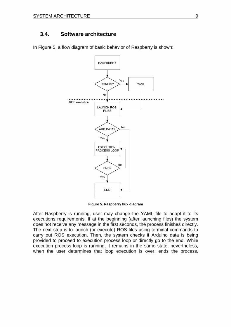
In Figure 5, a flow diagram of basic behavior of Raspberry is shown:
Figure 5. Raspberry flux diagram
After Raspberry is running, user may change the YAML file to adapt it to its executions requirements. If at the beginning (after launching files) the system does not receive any message in the first seconds, the process finishes directly. The next step is to launch (or execute) ROS files using terminal commands to carry out ROS execution. Then, the system checks if Arduino data is being provided to proceed to execution process loop or directly go to the end. While execution process loop is running, it remains in the same state, nevertheless, when the user determines that loop execution is over, ends the process.
10 Autonomous Rover for Indoor Localization
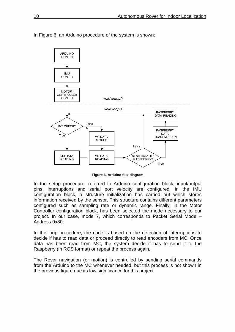
In Figure 6, an Arduino procedure of the system is shown:
Figure 6. Arduino flux diagram
In the setup procedure, referred to Arduino configuration block, input/output pins, interruptions and serial port velocity are configured. In the IMU configuration block, a structure initialization has carried out which stores information received by the sensor. This structure contains different parameters configured such as sampling rate or dynamic range. Finally, in the Motor Controller configuration block, has been selected the mode necessary to our project. In our case, mode 7, which corresponds to Packet Serial Mode – Address 0x80. In the loop procedure, the code is based on the detection of interruptions to decide if has to read data or proceed directly to read encoders from MC. Once data has been read from MC, the system decide if has to send it to the Raspberry (in ROS format) or repeat the process again. The Rover navigation (or motion) is controlled by sending serial commands from the Arduino to the MC whenever needed, but this process is not shown in the previous figure due its low significance for this project.
DETAILED SYSTEM DESIGN 11
CHAPTER 4. DETAILED SYSTEM DESIGN
In previous chapters have been mentioned the different elements used in this project without going into detail. In this chapter, a detailed description, pinouts, physical diagrams and technical specifications of each element used are shown. An aluminum 4WD1 Rover Kit from Lynxmotion have been mounted together with an IMU (MPU-9250) from InvenSense, two micro-controllers (Arduino Due, section 4.1, and Pololu 2x15A Motor Controller, section 4.3) and a micro-processor (Raspberry Pi 3 Model B, section 4.2). A brief introduction to communication interfaces (section 4.5) and applied power feeding (section 4.6) have been introduced too.
4.1. Arduino Due
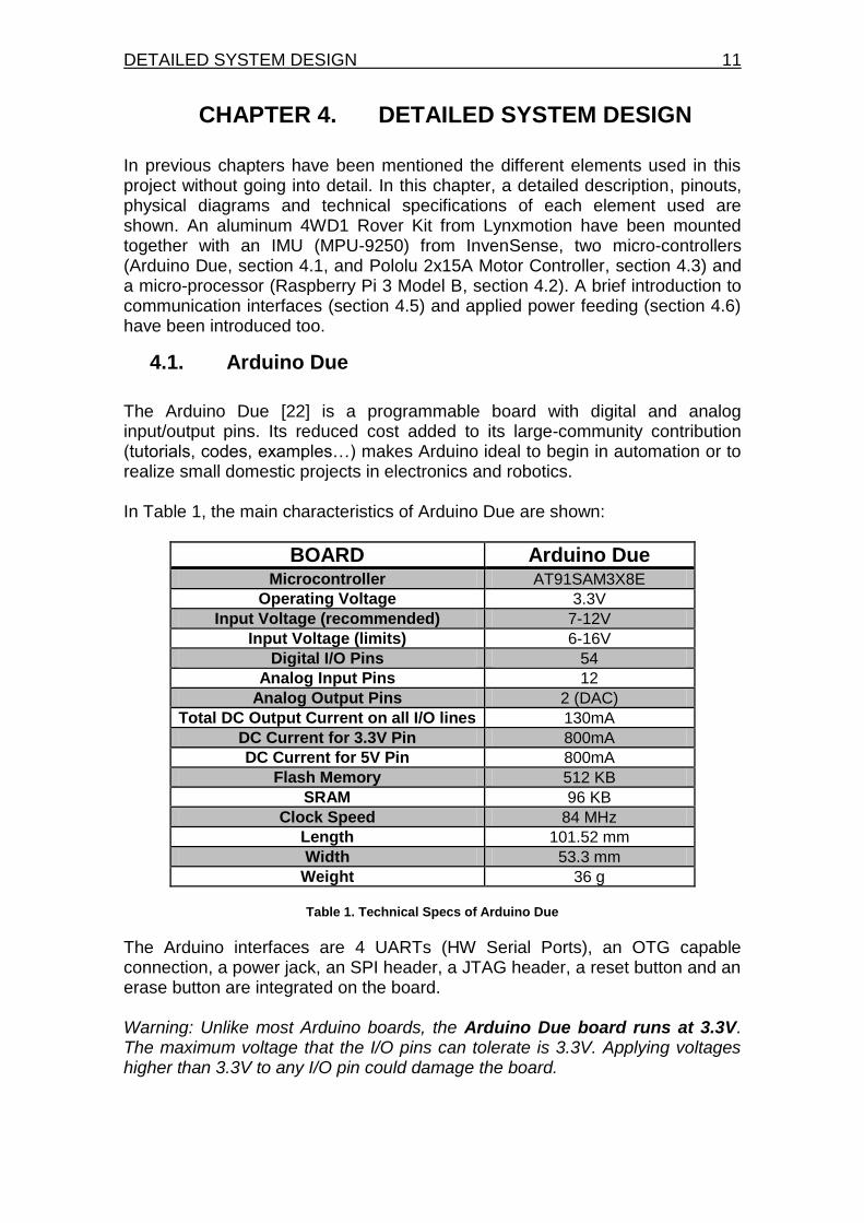
The Arduino Due [22] is a programmable board with digital and analog input/output pins. Its reduced cost added to its large-community contribution (tutorials, codes, examples…) makes Arduino ideal to begin in automation or to realize small domestic projects in electronics and robotics. In Table 1, the main characteristics of Arduino Due are shown:
BOARD Arduino Due Microcontroller AT91SAM3X8E
Operating Voltage 3.3V
Input Voltage (recommended) 7-12V
Input Voltage (limits) 6-16V
Digital I/O Pins 54
Analog Input Pins 12
Analog Output Pins 2 (DAC)
Total DC Output Current on all I/O lines 130mA
DC Current for 3.3V Pin 800mA
DC Current for 5V Pin 800mA
Flash Memory 512 KB
SRAM 96 KB
Clock Speed 84 MHz
Length 101.52 mm
Width 53.3 mm
Weight 36 g
Table 1. Technical Specs of Arduino Due
The Arduino interfaces are 4 UARTs (HW Serial Ports), an OTG capable connection, a power jack, an SPI header, a JTAG header, a reset button and an erase button are integrated on the board. Warning: Unlike most Arduino boards, the Arduino Due board runs at 3.3V. The maximum voltage that the I/O pins can tolerate is 3.3V. Applying voltages higher than 3.3V to any I/O pin could damage the board.
12 Autonomous Rover for Indoor Localization
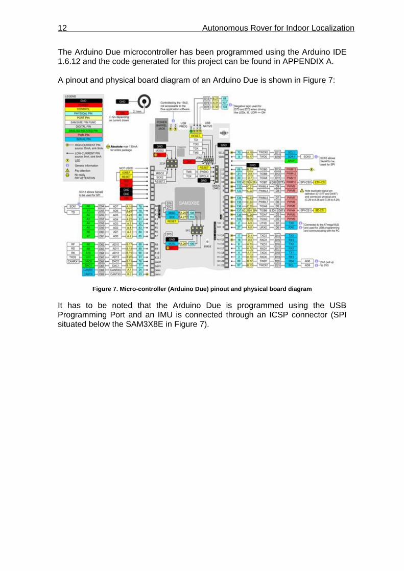
The Arduino Due microcontroller has been programmed using the Arduino IDE 1.6.12 and the code generated for this project can be found in APPENDIX A. A pinout and physical board diagram of an Arduino Due is shown in Figure 7:
Figure 7. Micro-controller (Arduino Due) pinout and physical board diagram
It has to be noted that the Arduino Due is programmed using the USB Programming Port and an IMU is connected through an ICSP connector (SPI situated below the SAM3X8E in Figure 7).
DETAILED SYSTEM DESIGN 13
4.2. Raspberry Pi 3 Model B
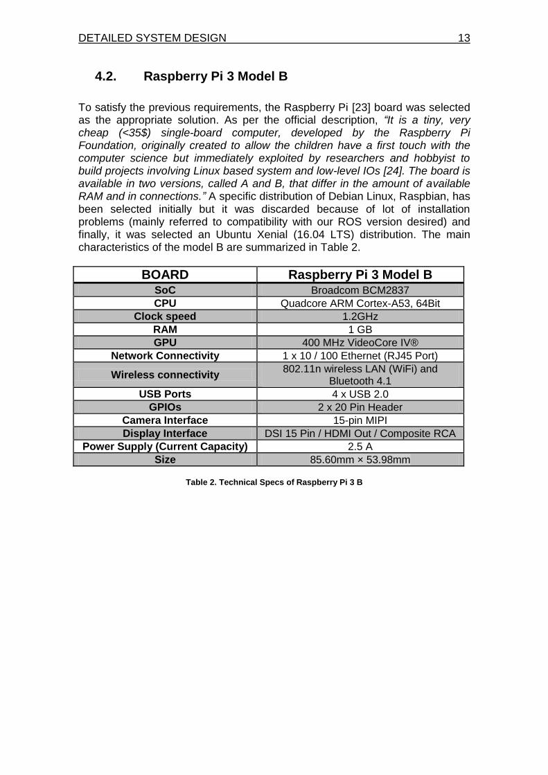
To satisfy the previous requirements, the Raspberry Pi [23] board was selected as the appropriate solution. As per the official description, “It is a tiny, very cheap (<35$) single-board computer, developed by the Raspberry Pi Foundation, originally created to allow the children have a first touch with the computer science but immediately exploited by researchers and hobbyist to build projects involving Linux based system and low-level IOs [24]. The board is available in two versions, called A and B, that differ in the amount of available RAM and in connections.” A specific distribution of Debian Linux, Raspbian, has been selected initially but it was discarded because of lot of installation problems (mainly referred to compatibility with our ROS version desired) and finally, it was selected an Ubuntu Xenial (16.04 LTS) distribution. The main characteristics of the model B are summarized in Table 2.
BOARD Raspberry Pi 3 Model B SoC Broadcom BCM2837
CPU Quadcore ARM Cortex-A53, 64Bit
Clock speed 1.2GHz
RAM 1 GB
GPU 400 MHz VideoCore IV®
Network Connectivity 1 x 10 / 100 Ethernet (RJ45 Port)
Wireless connectivity 802.11n wireless LAN (WiFi) and
Bluetooth 4.1
USB Ports 4 x USB 2.0
GPIOs 2 x 20 Pin Header
Camera Interface 15-pin MIPI
Display Interface DSI 15 Pin / HDMI Out / Composite RCA
Power Supply (Current Capacity) 2.5 A
Size 85.60mm × 53.98mm
Table 2. Technical Specs of Raspberry Pi 3 B
14 Autonomous Rover for Indoor Localization
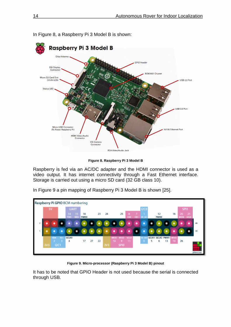
In Figure 8, a Raspberry Pi 3 Model B is shown:
Figure 8. Raspberry Pi 3 Model B
Raspberry is fed via an AC/DC adapter and the HDMI connector is used as a video output. It has internet connectivity through a Fast Ethernet interface. Storage is carried out using a micro SD card (32 GB class 10).
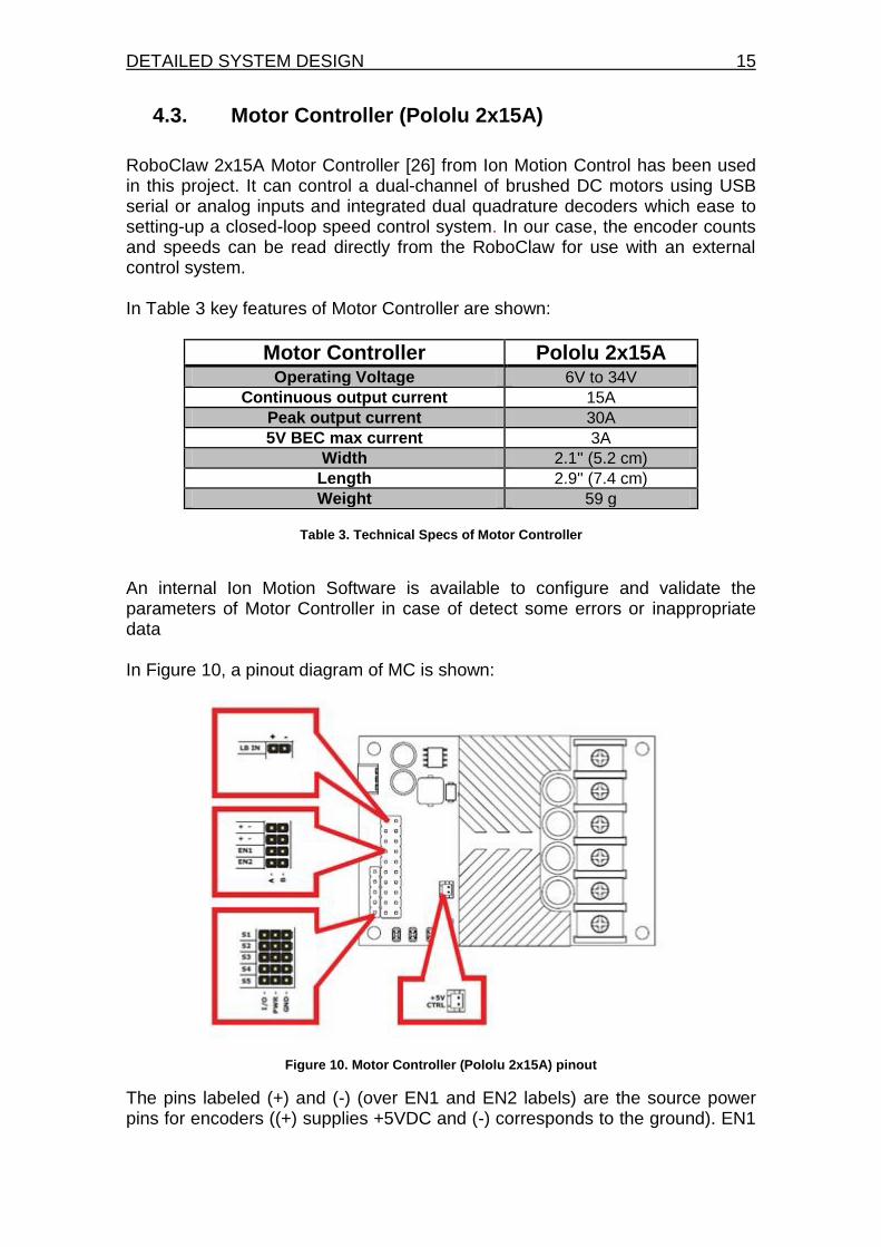
In Figure 9 a pin mapping of Raspberry Pi 3 Model B is shown [25].
Figure 9. Micro-processor (Raspberry Pi 3 Model B) pinout
It has to be noted that GPIO Header is not used because the serial is connected through USB.
DETAILED SYSTEM DESIGN 15
4.3. Motor Controller (Pololu 2x15A)
RoboClaw 2x15A Motor Controller [26] from Ion Motion Control has been used in this project. It can control a dual-channel of brushed DC motors using USB serial or analog inputs and integrated dual quadrature decoders which ease to setting-up a closed-loop speed control system. In our case, the encoder counts and speeds can be read directly from the RoboClaw for use with an external control system. In Table 3 key features of Motor Controller are shown:
Motor Controller Pololu 2x15A Operating Voltage 6V to 34V
Continuous output current 15A
Peak output current 30A
5V BEC max current 3A
Width 2.1'' (5.2 cm)
Length 2.9'' (7.4 cm)
Weight 59 g
Table 3. Technical Specs of Motor Controller
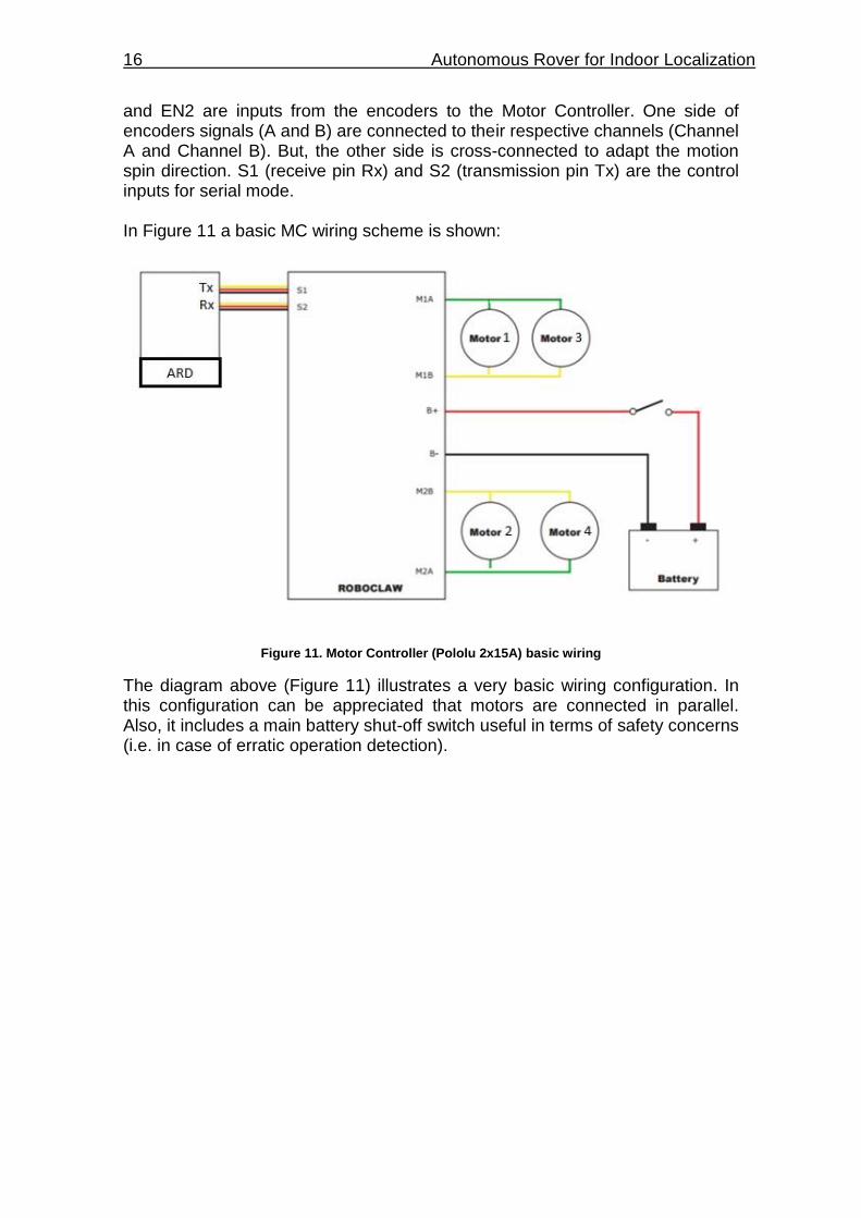
An internal Ion Motion Software is available to configure and validate the parameters of Motor Controller in case of detect some errors or inappropriate data In Figure 10, a pinout diagram of MC is shown:
Figure 10. Motor Controller (Pololu 2x15A) pinout
The pins labeled (+) and (-) (over EN1 and EN2 labels) are the source power pins for encoders ((+) supplies +5VDC and (-) corresponds to the ground). EN1
16 Autonomous Rover for Indoor Localization
and EN2 are inputs from the encoders to the Motor Controller. One side of encoders signals (A and B) are connected to their respective channels (Channel A and Channel B). But, the other side is cross-connected to adapt the motion spin direction. S1 (receive pin Rx) and S2 (transmission pin Tx) are the control inputs for serial mode. In Figure 11 a basic MC wiring scheme is shown:
Figure 11. Motor Controller (Pololu 2x15A) basic wiring
The diagram above (Figure 11) illustrates a very basic wiring configuration. In this configuration can be appreciated that motors are connected in parallel. Also, it includes a main battery shut-off switch useful in terms of safety concerns (i.e. in case of erratic operation detection).
DETAILED SYSTEM DESIGN 17
4.3.1. Motors and Encoders
Regarding to motors and encoders, the next hardware has been used:
4 x GH Motor 12vdc 30:1 200 rpm (6mm shaft) (GHM-16), which means the motor itself will spin 30 rotation before the output shaft does 1.
4 x Quadrature Motor Encoders 5V (QME-01) [27]. Motors specs and encoders specifications are shown in Table 4 and Table 5 respectively.
MOTORS GHM-16 Rated Voltage 12 vdc
Voltage Operating Range 6-12 vdc
Rated Load at 12 vdc 0.78 Kg-cm
No Load Speed at 12 vdc 200 rpm +/- 10%
Speed at Rated Load (0.78 Kg-cm) 163 rpm +/- 10%
No Load Current at 12 vdc < 115 mA
Current at Rated Load (0.78Kg-cm) < 285mA
Shaft End-Play Max 0.8 m/m
Insulation Resistance 10 Ohm at 300 vdc
Withstand Voltage 300 vdc for 1 second
Table 4. Technical Specs of Motors GHM-04
ENCODERS QME-01 Cycles/rev 100
Quadrature counts/rev 400
Voltage 5V
Frequency 30 KHz
Table 5. Technical Specs of Encoders QME-01
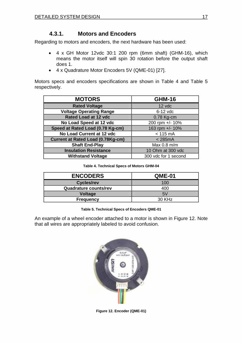
An example of a wheel encoder attached to a motor is shown in Figure 12. Note that all wires are appropriately labeled to avoid confusion.
Figure 12. Encoder (QME-01)
18 Autonomous Rover for Indoor Localization
4.4. IMU
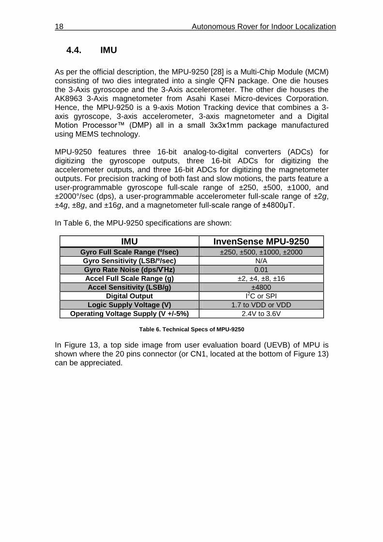
As per the official description, the MPU-9250 [28] is a Multi-Chip Module (MCM) consisting of two dies integrated into a single QFN package. One die houses the 3-Axis gyroscope and the 3-Axis accelerometer. The other die houses the AK8963 3-Axis magnetometer from Asahi Kasei Micro-devices Corporation. Hence, the MPU-9250 is a 9-axis Motion Tracking device that combines a 3-axis gyroscope, 3-axis accelerometer, 3-axis magnetometer and a Digital Motion Processor™ (DMP) all in a small 3x3x1mm package manufactured using MEMS technology. MPU-9250 features three 16-bit analog-to-digital converters (ADCs) for digitizing the gyroscope outputs, three 16-bit ADCs for digitizing the accelerometer outputs, and three 16-bit ADCs for digitizing the magnetometer outputs. For precision tracking of both fast and slow motions, the parts feature a user-programmable gyroscope full-scale range of ±250, ±500, ±1000, and ±2000°/sec (dps), a user-programmable accelerometer full-scale range of ±2g, ±4g, ±8g, and ±16g, and a magnetometer full-scale range of ±4800μT. In Table 6, the MPU-9250 specifications are shown:
IMU InvenSense MPU-9250 Gyro Full Scale Range (º/sec) ±250, ±500, ±1000, ±2000
Gyro Sensitivity (LSB/º/sec) N/A
Gyro Rate Noise (dps/ѴHz) 0.01
Accel Full Scale Range (g) ±2, ±4, ±8, ±16
Accel Sensitivity (LSB/g) ±4800
Digital Output I2C or SPI
Logic Supply Voltage (V) 1.7 to VDD or VDD
Operating Voltage Supply (V +/-5%) 2.4V to 3.6V
Table 6. Technical Specs of MPU-9250
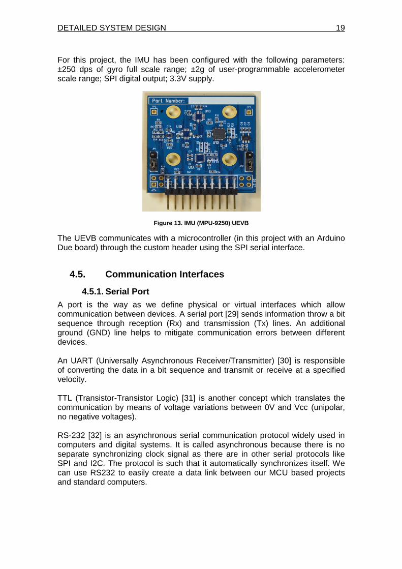
In Figure 13, a top side image from user evaluation board (UEVB) of MPU is shown where the 20 pins connector (or CN1, located at the bottom of Figure 13) can be appreciated.
DETAILED SYSTEM DESIGN 19
For this project, the IMU has been configured with the following parameters: ±250 dps of gyro full scale range; ±2g of user-programmable accelerometer scale range; SPI digital output; 3.3V supply.
Figure 13. IMU (MPU-9250) UEVB
The UEVB communicates with a microcontroller (in this project with an Arduino Due board) through the custom header using the SPI serial interface.
4.5. Communication Interfaces
4.5.1. Serial Port
A port is the way as we define physical or virtual interfaces which allow communication between devices. A serial port [29] sends information throw a bit sequence through reception (Rx) and transmission (Tx) lines. An additional ground (GND) line helps to mitigate communication errors between different devices. An UART (Universally Asynchronous Receiver/Transmitter) [30] is responsible of converting the data in a bit sequence and transmit or receive at a specified velocity. TTL (Transistor-Transistor Logic) [31] is another concept which translates the communication by means of voltage variations between 0V and Vcc (unipolar, no negative voltages). RS-232 [32] is an asynchronous serial communication protocol widely used in computers and digital systems. It is called asynchronous because there is no separate synchronizing clock signal as there are in other serial protocols like SPI and I2C. The protocol is such that it automatically synchronizes itself. We can use RS232 to easily create a data link between our MCU based projects and standard computers.
20 Autonomous Rover for Indoor Localization
4.5.2. SPI
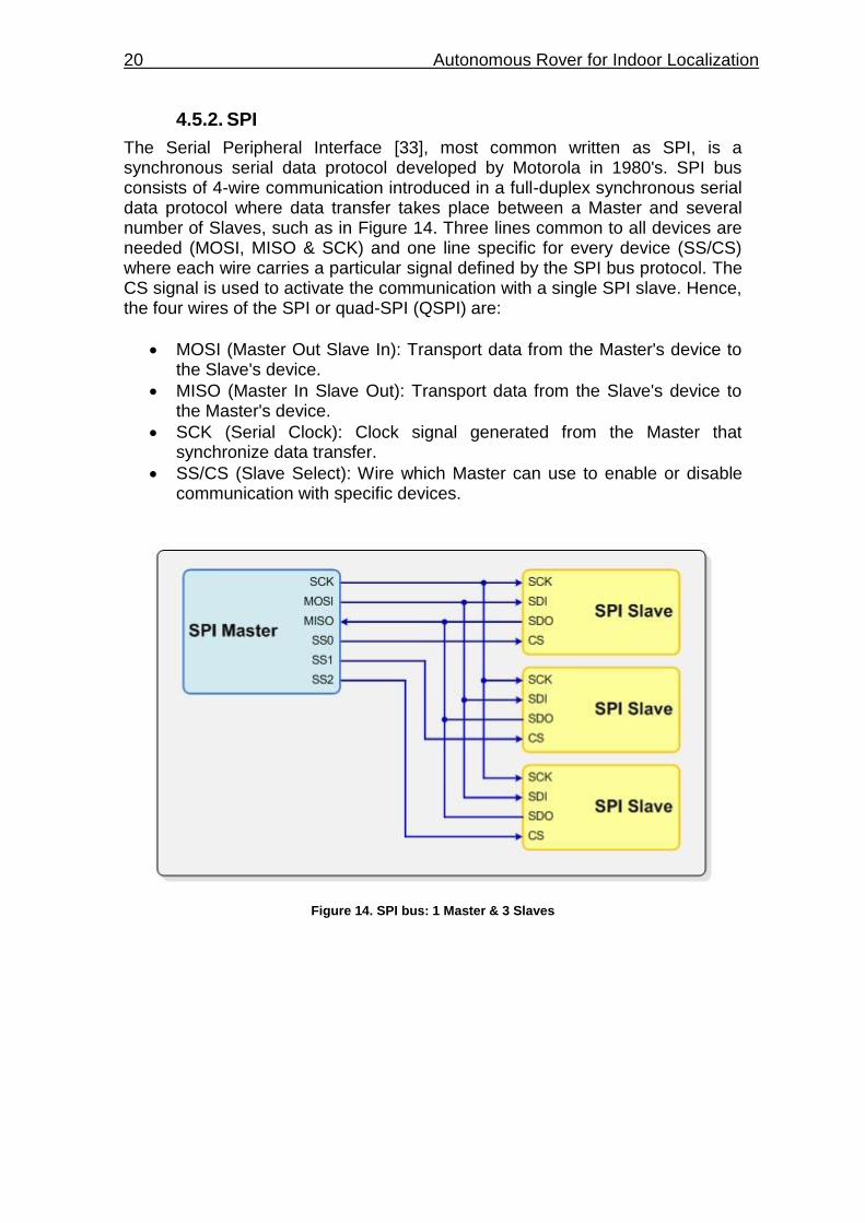
The Serial Peripheral Interface [33], most common written as SPI, is a synchronous serial data protocol developed by Motorola in 1980's. SPI bus consists of 4-wire communication introduced in a full-duplex synchronous serial data protocol where data transfer takes place between a Master and several number of Slaves, such as in Figure 14. Three lines common to all devices are needed (MOSI, MISO & SCK) and one line specific for every device (SS/CS) where each wire carries a particular signal defined by the SPI bus protocol. The CS signal is used to activate the communication with a single SPI slave. Hence, the four wires of the SPI or quad-SPI (QSPI) are:
MOSI (Master Out Slave In): Transport data from the Master's device to the Slave's device.
MISO (Master In Slave Out): Transport data from the Slave's device to the Master's device.
SCK (Serial Clock): Clock signal generated from the Master that synchronize data transfer.
SS/CS (Slave Select): Wire which Master can use to enable or disable communication with specific devices.
Figure 14. SPI bus: 1 Master & 3 Slaves
DETAILED SYSTEM DESIGN 21
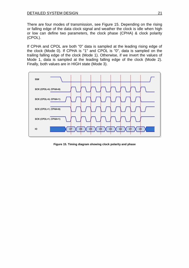
There are four modes of transmission, see Figure 15. Depending on the rising or falling edge of the data clock signal and weather the clock is idle when high or low can define two parameters, the clock phase (CPHA) & clock polarity (CPOL). If CPHA and CPOL are both "0" data is sampled at the leading rising edge of the clock (Mode 0). If CPHA is "1" and CPOL is "0", data is sampled on the trailing falling edge of the clock (Mode 1). Otherwise, if we invert the values of Mode 1, data is sampled at the leading falling edge of the clock (Mode 2). Finally, both values are in HIGH state (Mode 3).
Figure 15. Timing diagram showing clock polarity and phase
22 Autonomous Rover for Indoor Localization
4.6. Power feeding
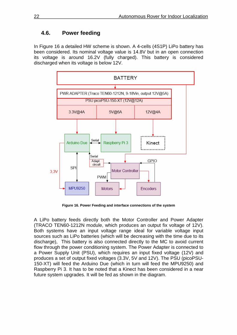
In Figure 16 a detailed HW scheme is shown. A 4-cells (4S1P) LiPo battery has been considered. Its nominal voltage value is 14.8V but in an open connection its voltage is around 16.2V (fully charged). This battery is considered discharged when its voltage is below 12V.
Figure 16. Power Feeding and interface connections of the system
A LiPo battery feeds directly both the Motor Controller and Power Adapter (TRACO TEN60-1212N module, which produces an output fix voltage of 12V). Both systems have an input voltage range ideal for variable voltage input sources such as LiPo batteries (which will be decreasing with the time due to its discharge), This battery is also connected directly to the MC to avoid current flow through the power conditioning system. The Power Adapter is connected to a Power Supply Unit (PSU), which requires an input fixed voltage (12V) and produces a set of output fixed voltages (3.3V, 5V and 12V). The PSU (picoPSU-150-XT) will feed the Arduino Due (which in turn will feed the MPU9250) and Raspberry Pi 3. It has to be noted that a Kinect has been considered in a near future system upgrades. It will be fed as shown in the diagram.
DETAILED SYSTEM DESIGN 23
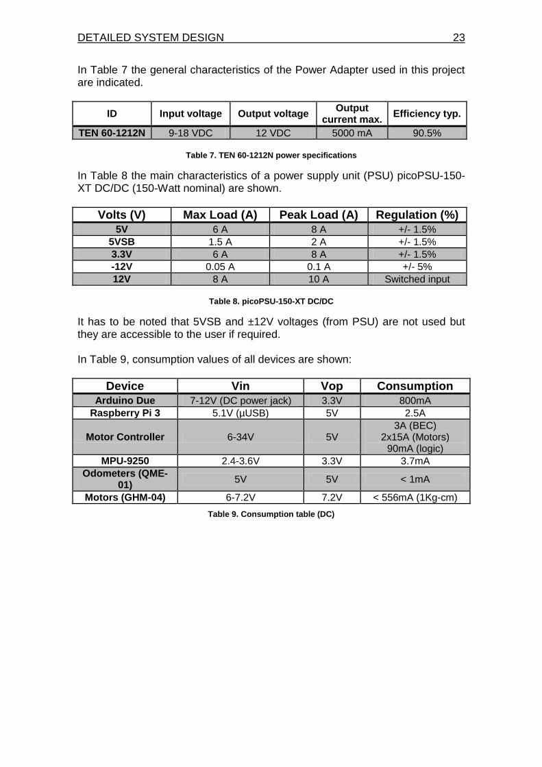
In Table 7 the general characteristics of the Power Adapter used in this project are indicated.
ID Input voltage Output voltage Output
current max. Efficiency typ.
TEN 60-1212N 9-18 VDC 12 VDC 5000 mA 90.5%
Table 7. TEN 60-1212N power specifications
In Table 8 the main characteristics of a power supply unit (PSU) picoPSU-150-XT DC/DC (150-Watt nominal) are shown.
Volts (V) Max Load (A) Peak Load (A) Regulation (%)
5V 6 A 8 A +/- 1.5%
5VSB 1.5 A 2 A +/- 1.5%
3.3V 6 A 8 A +/- 1.5%
-12V 0.05 A 0.1 A +/- 5%
12V 8 A 10 A Switched input
Table 8. picoPSU-150-XT DC/DC
It has to be noted that 5VSB and ±12V voltages (from PSU) are not used but they are accessible to the user if required. In Table 9, consumption values of all devices are shown:
Device Vin Vop Consumption
Arduino Due 7-12V (DC power jack) 3.3V 800mA
Raspberry Pi 3 5.1V (µUSB) 5V 2.5A
Motor Controller 6-34V 5V 3A (BEC)
2x15A (Motors) 90mA (logic)
MPU-9250 2.4-3.6V 3.3V 3.7mA
Odometers (QME-01)
5V 5V < 1mA
Motors (GHM-04) 6-7.2V 7.2V < 556mA (1Kg-cm)
Table 9. Consumption table (DC)

24 Autonomous Rover for Indoor Localization
ROS 25
CHAPTER 5. ROS
As per the official description [20], "the Robot Operating System (ROS) is a flexible framework for writing robot software. It is a collection of tools, libraries, and conventions that aim to simplify the task of creating complex and robust robot behavior across a wide variety of robotic platforms." It provides typical features as any other OS like hardware abstractions and low-level device control, programming language independence, implementation of a wide range commonly-used functionality, message-passing between processes and standardized package management [20]. A ROS system is comprised of a number of independent nodes, each of which communicates with the other nodes using a publish/subscribe messaging model. ROS is an important tool related with the robot development that allows to the user through its OS in an open source system to deal with its software and research about it. Moreover, ROS has appeared as a robotic OS development tool which has been accepted by the developers' community, companies and I+D research centers. ROS has been installed in an Ubuntu Xenial (16.04 LTS) running in a Raspberry Pi 3 Model B and it is controlled by terminal commands since ROS is considered as a non-graphical OS. User has to configure the system (section 5.1), then execute the corresponding modules via commands through a terminal (section 5.2). During module execution, they process input data and provide information from the output (localization, 5.3.1). At the end of this chapter, an execution ROS user manual is provided (section 5.4).
5.1. ENVIRONMENT SETUP
First of all it needs to know which version of ROS is desired to install and check which OS is available for that version. In this project, the latest version has been installed, also known as ROS Kinetic which has been installed in an Ubuntu Xenial (16.04 LTS) environment. ROS website [20] has an installation tutorial for each ROS version [34]. When choosing a version for ROS, it is important to know if the modules that are being used are compatible with the installed version; otherwise, it will produce a lot of problems to develop the main functions of the system. ROS is composed from several modules, being /roscore the principal, which is the most important module to allow ROS to execute other ones, such as rosserial_arduino or robot_localization. rosserial_arduino is responsible of allow direct communication between Arduino Due and Raspberry Pi 3, and robot_localization of process sensor data and produce a TPVA output.
26 Autonomous Rover for Indoor Localization
In this project, Desktop-Full Installation from ROS download website [34] has been installed where rqt, rviz, robot-generic libraries, 2D/3D simulators, navigation and 2D/3D perception packages are included. No more ROS packages are needed for this project, but if needed, there are many different libraries and tools in ROS that could be installed individually. Once installed, the corresponding modules and packages have to be called via terminal and execute them because ROS does not have graphical interface. When talking about the non-existing graphical interface, it has to be remarked that is possible to execute some packages (rviz or rqt_graph) where a simulation in a graphical interface is reflected, but, in general ROS is considered as non-graphical OS. It has to be noted that all modules have associated almost one node. A node can share information (publish) associated to a series of sensors, which are identified by standard messages (topics). On the other hand, a node can access (subscribe) to information (topic) shared by other node.
5.1.1. YAML configuration file
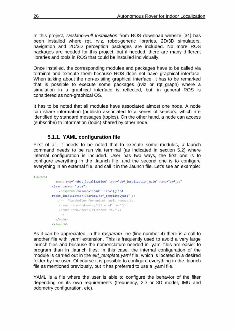
First of all, it needs to be noted that to execute some modules, a launch command needs to be run via terminal (as indicated in section 5.2) where internal configuration is included. User has two ways, the first one is to configure everything in the .launch file, and the second one is to configure everything in an external file, and call it in the .launch file. Let's see an example: <launch>
<node pkg="robot_localization" type="ekf_localization_node" name="ekf_se"
clear_params="true">
<rosparam command="load" file="$(find
robot_localization)/params/ekf_template.yaml" />
<!-- Placeholder for output topic remapping
<remap from="odometry/filtered" to=""/>
<remap from="accel/filtered" to=""/>
-->
</node>
</launch>
As it can be appreciated, in the rosparam line (line number 4) there is a call to another file with .yaml extension. This is frequently used to avoid a very large launch files and because the nomenclature needed in .yaml files are easier to program than in .launch files. In this case, the internal configuration of the module is carried out in the ekf_template.yaml file, which is located in a desired folder by the user. Of course it is possible to configure everything in the .launch file as mentioned previously, but it has preferred to use a .yaml file. YAML is a file where the user is able to configure the behavior of the filter depending on its own requirements (frequency, 2D or 3D model, IMU and odometry configuration, etc).
ROS 27
5.2. MOST USED TERMINAL COMMANDS
As mentioned, ROS works under terminal command execution. The first command to take into account is /roscore, which is a collection of nodes that are pre-requisites of a ROS-based system. You must have a /roscore module running in order for ROS nodes to communicate. /roscreate-pkg creates common Manifest, CMakeLists, Doxygen and other files necessary for a new ROS package. Example: create a package called abcd with 3 different dependencies (roscpp, rospy & std_msgs). roscreate-pkg abcd roscpp rospy std_msgs /rosrun allows you to run an executable in an arbitrary package without having to access to containing location of the file. Example: rosrun roscpp_tutorials talker /roslaunch launches a set of nodes from an XML configuration file and includes support for launching on remote machines. Example: execute a .launch from robot_localization called ekf_template, roslaunch robot_localization ekf_template.launch /rqt_graph displays an interactive graph of ROS nodes and topics. Example: rosrun rqt_graph rqt_graph /rviz displays something in a 3D world, and likely has some options available in the displays list, i.e. odometry, point cloud, axis, etc. Example: rosrun rviz rviz
5.3. PUBLISHERS AND SUBSCRIBERS
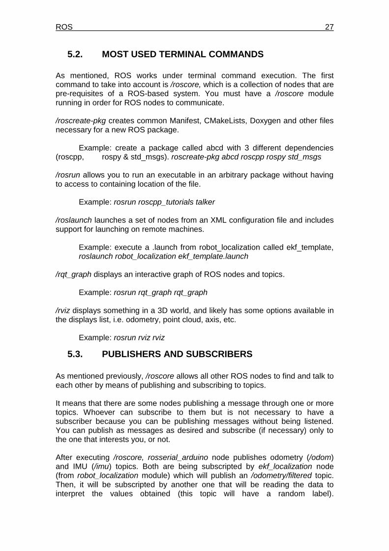
As mentioned previously, /roscore allows all other ROS nodes to find and talk to each other by means of publishing and subscribing to topics. It means that there are some nodes publishing a message through one or more topics. Whoever can subscribe to them but is not necessary to have a subscriber because you can be publishing messages without being listened. You can publish as messages as desired and subscribe (if necessary) only to the one that interests you, or not. After executing /roscore, rosserial_arduino node publishes odometry (/odom) and IMU (/imu) topics. Both are being subscripted by ekf_localization node (from robot_localization module) which will publish an /odometry/filtered topic. Then, it will be subscripted by another one that will be reading the data to interpret the values obtained (this topic will have a random label).
28 Autonomous Rover for Indoor Localization
ekf_localization node is mandated to manage data obtained from previous topics (/odom and /imu in our case).
Figure 17. Basic scheme of modules (nodes and topics)
/odom and /imu topics are showing the values obtained directly from Arduino (through rosserial_arduino) without manipulate them. Otherwise, /odometry/filtered topic is generated by the ekf_localization node where its output provides a localization solution, explained in the next subchapter.
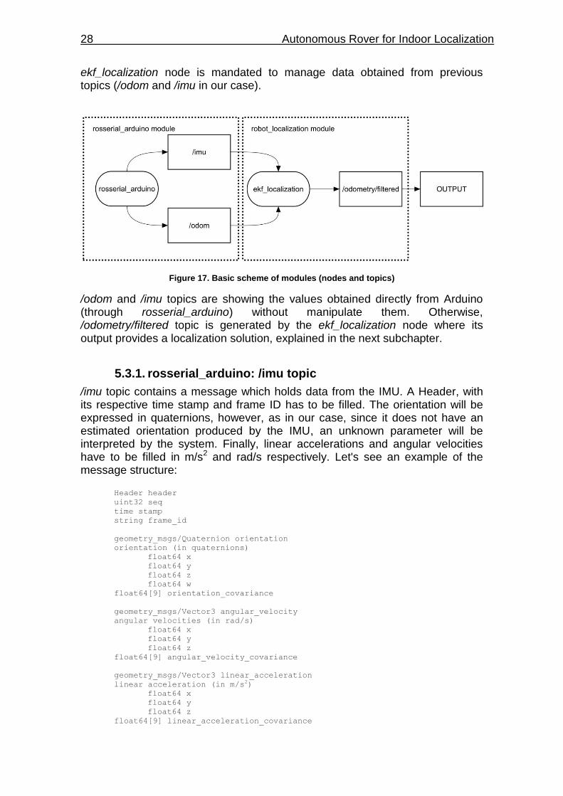
5.3.1. rosserial_arduino: /imu topic
/imu topic contains a message which holds data from the IMU. A Header, with its respective time stamp and frame ID has to be filled. The orientation will be expressed in quaternions, however, as in our case, since it does not have an estimated orientation produced by the IMU, an unknown parameter will be interpreted by the system. Finally, linear accelerations and angular velocities have to be filled in m/s2 and rad/s respectively. Let's see an example of the message structure: Header header
uint32 seq
time stamp
string frame_id
geometry_msgs/Quaternion orientation
orientation (in quaternions)
float64 x
float64 y
float64 z
float64 w
float64[9] orientation_covariance
geometry_msgs/Vector3 angular_velocity
angular velocities (in rad/s)
float64 x
float64 y
float64 z
float64[9] angular_velocity_covariance
geometry_msgs/Vector3 linear_acceleration
linear acceleration (in m/s2)
float64 x
float64 y
float64 z
float64[9] linear_acceleration_covariance
ROS 29
It needs mentioning that if the covariance of the measurement (orientation, angular velocity and linear acceleration) is unknown, it shouldn't be filled in, as in our case.
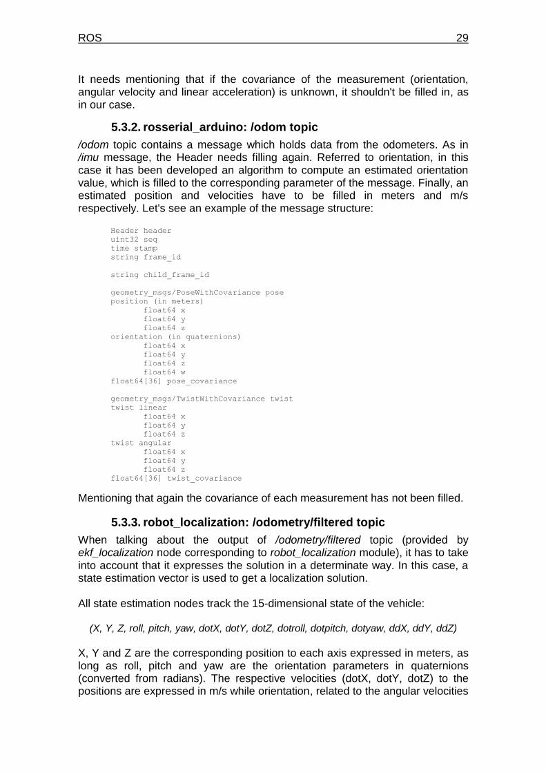
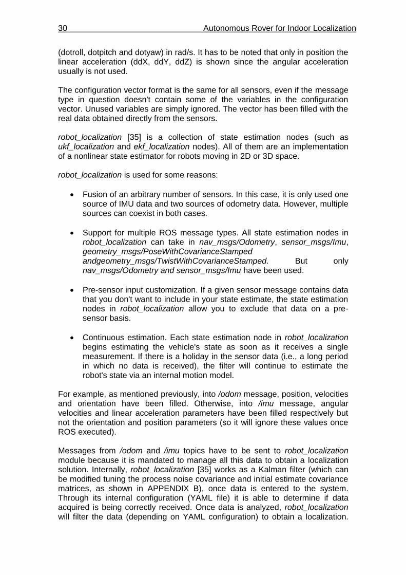
5.3.2. rosserial_arduino: /odom topic
/odom topic contains a message which holds data from the odometers. As in /imu message, the Header needs filling again. Referred to orientation, in this case it has been developed an algorithm to compute an estimated orientation value, which is filled to the corresponding parameter of the message. Finally, an estimated position and velocities have to be filled in meters and m/s respectively. Let's see an example of the message structure: Header header
uint32 seq
time stamp
string frame_id
string child_frame_id
geometry_msgs/PoseWithCovariance pose
position (in meters)
float64 x
float64 y
float64 z
orientation (in quaternions)
float64 x
float64 y
float64 z
float64 w
float64[36] pose_covariance
geometry_msgs/TwistWithCovariance twist
twist linear
float64 x
float64 y
float64 z
twist angular
float64 x
float64 y
float64 z
float64[36] twist_covariance
Mentioning that again the covariance of each measurement has not been filled.
5.3.3. robot_localization: /odometry/filtered topic
When talking about the output of /odometry/filtered topic (provided by ekf_localization node corresponding to robot_localization module), it has to take into account that it expresses the solution in a determinate way. In this case, a state estimation vector is used to get a localization solution. All state estimation nodes track the 15-dimensional state of the vehicle:
(X, Y, Z, roll, pitch, yaw, dotX, dotY, dotZ, dotroll, dotpitch, dotyaw, ddX, ddY, ddZ)
X, Y and Z are the corresponding position to each axis expressed in meters, as long as roll, pitch and yaw are the orientation parameters in quaternions (converted from radians). The respective velocities (dotX, dotY, dotZ) to the positions are expressed in m/s while orientation, related to the angular velocities
30 Autonomous Rover for Indoor Localization
(dotroll, dotpitch and dotyaw) in rad/s. It has to be noted that only in position the linear acceleration (ddX, ddY, ddZ) is shown since the angular acceleration usually is not used. The configuration vector format is the same for all sensors, even if the message type in question doesn't contain some of the variables in the configuration vector. Unused variables are simply ignored. The vector has been filled with the real data obtained directly from the sensors. robot_localization [35] is a collection of state estimation nodes (such as ukf_localization and ekf_localization nodes). All of them are an implementation of a nonlinear state estimator for robots moving in 2D or 3D space. robot_localization is used for some reasons:
Fusion of an arbitrary number of sensors. In this case, it is only used one source of IMU data and two sources of odometry data. However, multiple sources can coexist in both cases.
Support for multiple ROS message types. All state estimation nodes in robot_localization can take in nav_msgs/Odometry, sensor_msgs/Imu, geometry_msgs/PoseWithCovarianceStamped andgeometry_msgs/TwistWithCovarianceStamped. But only nav_msgs/Odometry and sensor_msgs/Imu have been used.
Pre-sensor input customization. If a given sensor message contains data that you don't want to include in your state estimate, the state estimation nodes in robot_localization allow you to exclude that data on a pre-sensor basis.
Continuous estimation. Each state estimation node in robot_localization begins estimating the vehicle's state as soon as it receives a single measurement. If there is a holiday in the sensor data (i.e., a long period in which no data is received), the filter will continue to estimate the robot's state via an internal motion model.
For example, as mentioned previously, into /odom message, position, velocities and orientation have been filled. Otherwise, into /imu message, angular velocities and linear acceleration parameters have been filled respectively but not the orientation and position parameters (so it will ignore these values once ROS executed). Messages from /odom and /imu topics have to be sent to robot_localization module because it is mandated to manage all this data to obtain a localization solution. Internally, robot_localization [35] works as a Kalman filter (which can be modified tuning the process noise covariance and initial estimate covariance matrices, as shown in APPENDIX B), once data is entered to the system. Through its internal configuration (YAML file) it is able to determine if data acquired is being correctly received. Once data is analyzed, robot_localization will filter the data (depending on YAML configuration) to obtain a localization.
ROS 31
/imu and /odom filter state vectors can be modified giving to the user a greater control over which values from each measurement are fed to the filter (see APPENDIX C). robot_localization publishes a topic called /odometry/filtered (as mentioned previously) which we have to subscribe at the end to get the localization. The name of the topic is not the most appropriate because it seems that IMU data does not have relationship with the system, but it has in consideration. robot_localization receive data from odometer generally to estimate a position and helps with the IMU data to integrate both and obtain a solution.
5.4. EXECUTING ROS
Following the next steps, you will be able to execute a ROS module to see which data is being read.
1. Prepare Arduino code and update it to the microcontroller (see Arduino code in APPENDIX A)
2. Insert USB cable from Arduino USB Programming Port to Raspberry Pi to
allow communication with rosserial_arduino.
3. Open a terminal and execute the /roscore command to allow all ROS publications and subscriptions from different nodes.
4. In a new terminal, execute the program in two steps. First, insert sudo
chmod 777 /dev/tty* to allow to communicate with the indicated port of the Raspberry (note that tty* has to be supplied by the corresponding name of the port, i.e., /ttyACM0). Move to /dev/ folder find it. Then, use rosrun rosserial_python serial_node.py /dev/tty* to execute the Arduino program in ROS.
5. In a new terminal, if setup.bash isn't configured, insert source
/opt/ros/kinetic/setup.bash and then introduce the command to execute a previous launch program to obtain, through the received data from sensors, a final solution as an output of robot_localization with its corresponding estimated position.
6. Once executed previous commands, you can check individually each node to know which data is being plotted, i.e., rostopic echo /imu.

32 Autonomous Rover for Indoor Localization
TESTING & VALIDATION 33
CHAPTER 6. TESTING & VALIDATION
All of the following tests and validations have been developed under the same conditions, a flat floor in an indoor room. The Rover will be working in a UTC time reference frame. Coordinate and Attitude vectors are set to (0,0,0) respect the Rover (local reference frame) and not respect to magnetic North. Both the Rover and the IMU share the same axis and gravity center. To carry out the system test and validation, has been compared the /odom topic with /odometry/filtered topic (remember that /odom topic is a conversion from encoders data to odometry information and /odometry/filtered is a computed solution obtained from /odom and /imu topics at the same time). The main reason is intended to interpret the behavior of robot_localization module once sensor data have been fused to obtain a solution. On the screen, both topics are being plotted at the same time for comparison. The paths and times have been forced to do a determinate behavior to allow writing down data notes comfortably (i.e. in intervals of 60 seconds between stages). Once Rover has stopped, the real values on the floor and the values obtained from the /odometry/filtered topic are pointed on a table for later comparison. Then, a comparison of orientation between /odom and /odometry/filtered topics are carried out with the objective to show the correction applied by the IMU in the /odometry/filtered. Note that in the orientation (Yaw) is only provided from /odom topic.
34 Autonomous Rover for Indoor Localization
6.1. Forward Maneuver Test
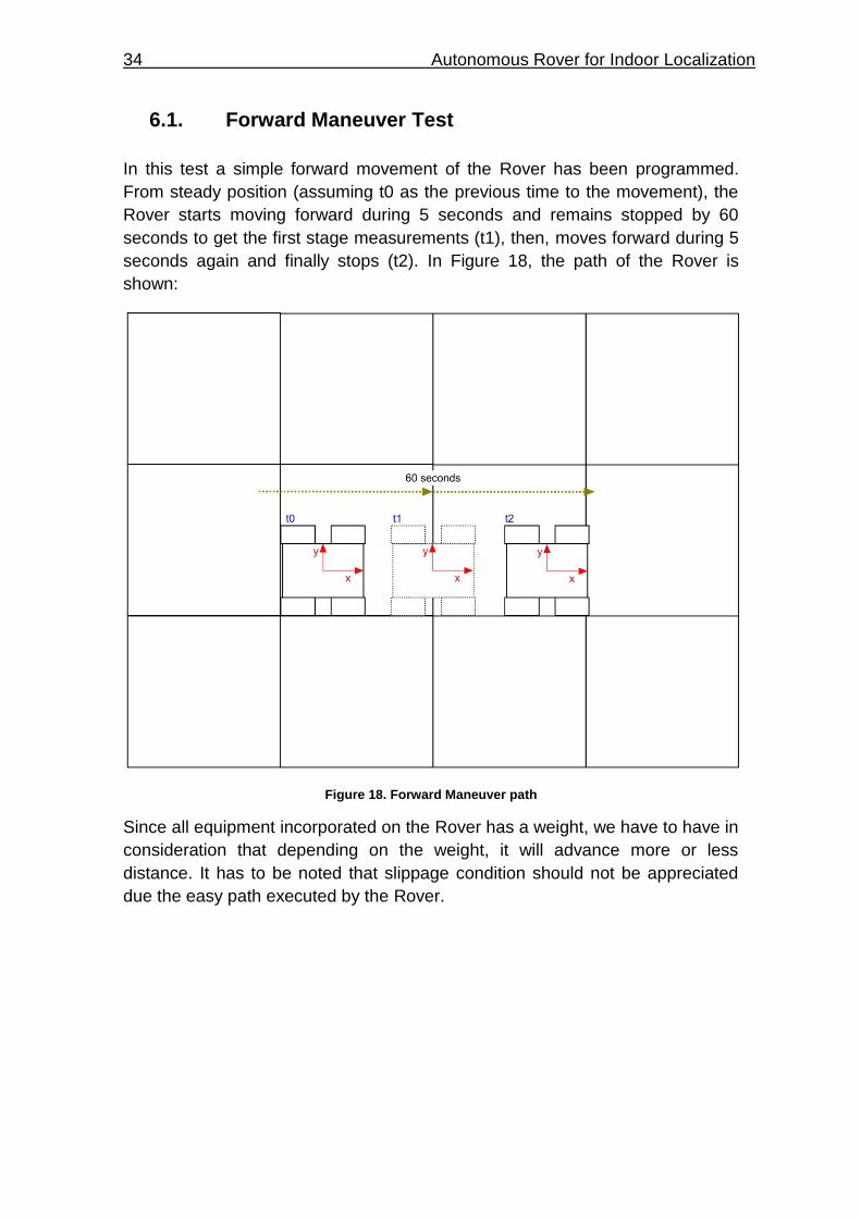
In this test a simple forward movement of the Rover has been programmed.
From steady position (assuming t0 as the previous time to the movement), the
Rover starts moving forward during 5 seconds and remains stopped by 60
seconds to get the first stage measurements (t1), then, moves forward during 5
seconds again and finally stops (t2). In Figure 18, the path of the Rover is
shown:
Figure 18. Forward Maneuver path
Since all equipment incorporated on the Rover has a weight, we have to have in
consideration that depending on the weight, it will advance more or less
distance. It has to be noted that slippage condition should not be appreciated
due the easy path executed by the Rover.
TESTING & VALIDATION 35
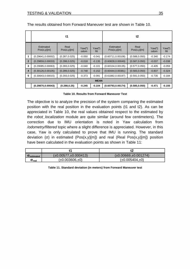
The results obtained from Forward Maneuver test are shown in Table 10.
t1 t2
Estimated
Pos(x,y)[m] Real
Pos(x,y)[m]
Yaw(º) odom
Yaw(º)
filt
Estimated Pos(x,y)[m]
Real Pos(x,y)[m]
Yaw(º) odom
Yaw(º)
filt
1 (0.29641,0.00002) (0.287,0.025) -0.050 -0.041 (0.60711,0.00108) (0.588,0.050) -0.340 -0.174
2 (0.29859,0.00033) (0.288,0.025) -0.018 -0.135 (0.60828,0.00049) (0.587,0.050) -0.037 -0.038
3 (0.29085,0.00063) (0.283,0.025) -0.040 -0.101 (0.60104,0.00135) (0.577,0.050) -0.405 -0.059
4 (0.30126,0.00105) (0.289,0.025) -0.748 -0.152 (0.60444,0.00381) (0.583,0.050) -0.837 -0.324
5 (0.30643,0.00015) (0.293,0.025) -0.373 -0.091 (0.61882,0.00197) (0.591,0.050) -0.735 -0.184
MEAN
(0.29870,0.00043) (0.288,0.25) -0.245 -0.104 (0.60793,0.00174) (0.585,0.050) -0.471 -0.155
Table 10. Results from Forward Maneuver Test
The objective is to analyze the precision of the system comparing the estimated
position with the real position in the evaluation points (t1 and t2). As can be
appreciated in Table 10, the real values obtained respect to the estimated by
the robot_localization module are quite similar (around few centimeters). The
correction due to IMU orientation is noted in Yaw calculation from
/odometry/filtered topic where a slight difference is appreciated. However, in this
case, Yaw is only calculated to prove that IMU is running. The standard
deviation (σ) in estimated (Pos(x,y)[m]) and real (Real Pos(x,y)[m]) position
have been calculated in the evaluation points as shown in Table 11:
t1 t2
σestimated (±0.00577,±0.000413) (±0.00669,±0.001274)
σreal (±0.003606,±0) (±0.005404,±0)
Table 11. Standard deviation (in meters) from Forward Maneuver test
36 Autonomous Rover for Indoor Localization
6.2. Forward-Backward Maneuver Test
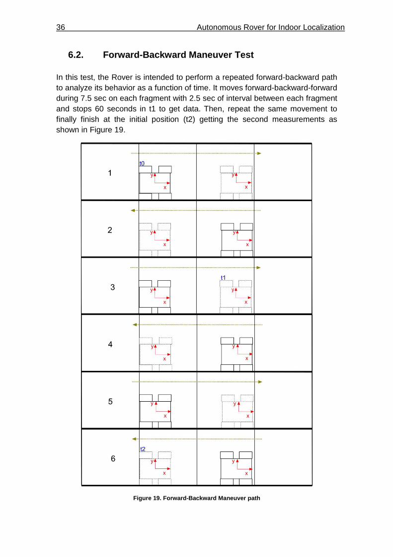
In this test, the Rover is intended to perform a repeated forward-backward path
to analyze its behavior as a function of time. It moves forward-backward-forward
during 7.5 sec on each fragment with 2.5 sec of interval between each fragment
and stops 60 seconds in t1 to get data. Then, repeat the same movement to
finally finish at the initial position (t2) getting the second measurements as
shown in Figure 19.
Figure 19. Forward-Backward Maneuver path
TESTING & VALIDATION 37
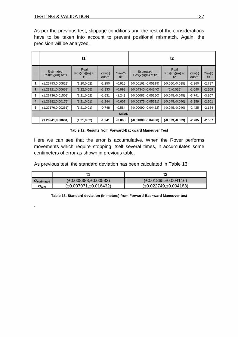
As per the previous test, slippage conditions and the rest of the considerations
have to be taken into account to prevent positional mismatch. Again, the
precision will be analyzed.
t1 t2
Estimated
Pos(x,y)(m) at t1
Real Pos(x,y)(m) at
t1
Yaw(º) odom
Yaw(º)
filt
Estimated Pos(x,y)(m) at t2
Real Pos(x,y)(m) at
t2
Yaw(º) odom
Yaw(º)
filt
1 (1.25793,0.00823) (1.20,0.02) -1.250 -0.915 (-0.00161,-0.05119) (-0.060,-0.035) -2.960 -2.737
2 (1.28121,0.00653) (1.22,0.05) -1.333 -0.993 (-0.04340,-0.04540) (0,-0.035) -1.040 -2.309
3 (1.26736,0.01508) (1.21,0.02) -1.631 -1.243 (-0.00082,-0.05260) (-0.045,-0.045) -3.741 -3.107
4 (1.26882,0.00176) (1.21,0.01) -1.244 -0.607 (-0.00375,-0.05321) (-0.045,-0.040) -3.359 -2.501
5 (1.27176,0.00261) (1.21,0.01) -0.748 -0.584 (-0.00090,-0.04452) (-0.045,-0.040) -2.425 -2.184
MEAN
(1.26941,0.00684) (1.21,0.02) -1.241 -0.868 (-0.01009,-0.04938) (-0.039,-0.039) -2.705 -2.567
Table 12. Results from Forward-Backward Maneuver Test
Here we can see that the error is accumulative. When the Rover performs
movements which require stopping itself several times, it accumulates some
centimeters of error as shown in previous table.
As previous test, the standard deviation has been calculated in Table 13:
t1 t2
σestimated (±0.008383,±0.00533) (±0.01865,±0.004116)
σreal (±0.007071,±0.016432) (±0.022749,±0.004183)
Table 13. Standard deviation (in meters) from Forward-Backward Maneuver test
.
38 Autonomous Rover for Indoor Localization
6.3. Turn Maneuver Test
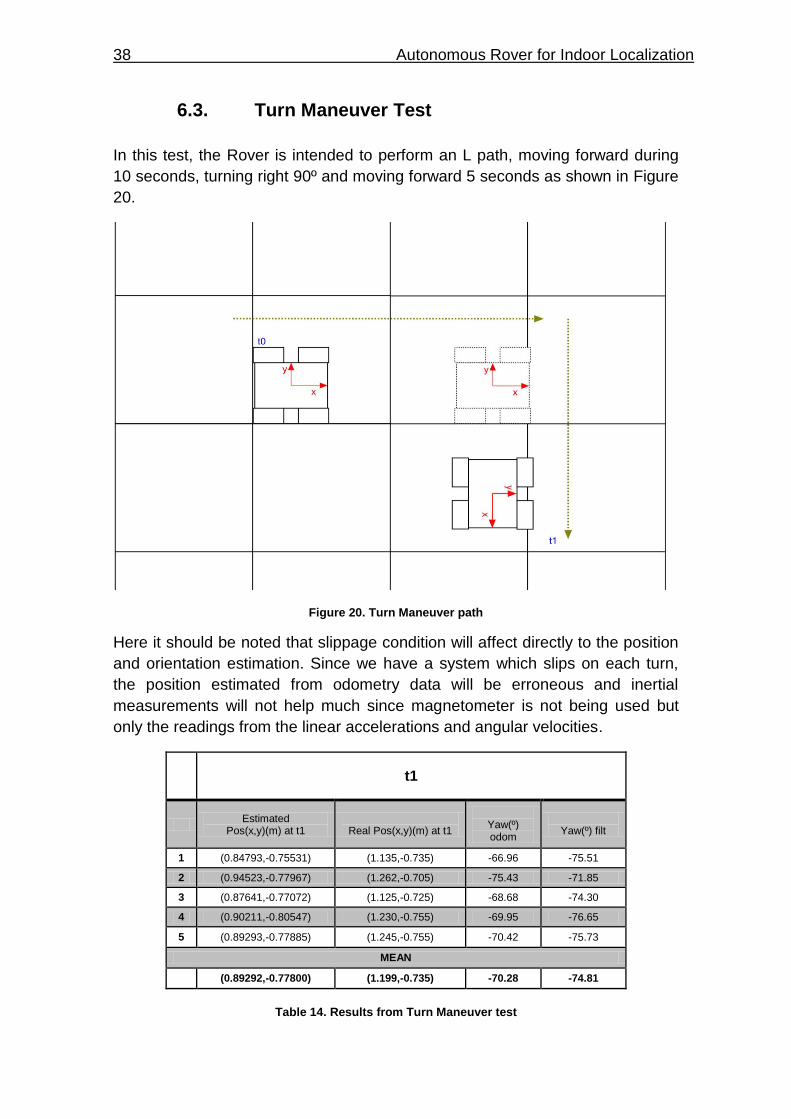
In this test, the Rover is intended to perform an L path, moving forward during
10 seconds, turning right 90º and moving forward 5 seconds as shown in Figure
20.
Figure 20. Turn Maneuver path
Here it should be noted that slippage condition will affect directly to the position
and orientation estimation. Since we have a system which slips on each turn,
the position estimated from odometry data will be erroneous and inertial
measurements will not help much since magnetometer is not being used but
only the readings from the linear accelerations and angular velocities.
t1
Estimated
Pos(x,y)(m) at t1
Real Pos(x,y)(m) at t1
Yaw(º) odom
Yaw(º) filt
1 (0.84793,-0.75531) (1.135,-0.735) -66.96 -75.51
2 (0.94523,-0.77967) (1.262,-0.705) -75.43 -71.85
3 (0.87641,-0.77072) (1.125,-0.725) -68.68 -74.30
4 (0.90211,-0.80547) (1.230,-0.755) -69.95 -76.65
5 (0.89293,-0.77885) (1.245,-0.755) -70.42 -75.73
MEAN
(0.89292,-0.77800) (1.199,-0.735) -70.28 -74.81
Table 14. Results from Turn Maneuver test
TESTING & VALIDATION 39
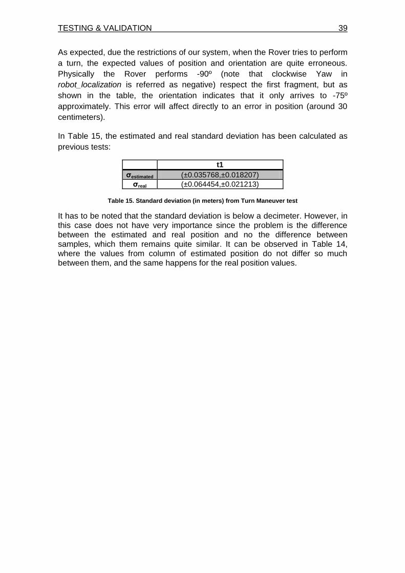
As expected, due the restrictions of our system, when the Rover tries to perform
a turn, the expected values of position and orientation are quite erroneous.
Physically the Rover performs -90º (note that clockwise Yaw in
robot_localization is referred as negative) respect the first fragment, but as
shown in the table, the orientation indicates that it only arrives to -75º
approximately. This error will affect directly to an error in position (around 30
centimeters).
In Table 15, the estimated and real standard deviation has been calculated as
previous tests:
t1
σestimated (±0.035768,±0.018207)
σreal (±0.064454,±0.021213)
Table 15. Standard deviation (in meters) from Turn Maneuver test
It has to be noted that the standard deviation is below a decimeter. However, in this case does not have very importance since the problem is the difference between the estimated and real position and no the difference between samples, which them remains quite similar. It can be observed in Table 14, where the values from column of estimated position do not differ so much between them, and the same happens for the real position values.

40 Autonomous Rover for Indoor Localization
CONCLUSIONS 41
CHAPTER 7. CONCLUSIONS
This project has been finished obtaining a real-time ROS localization service with the integration of different systems (Arduino, Raspberry and Motor Controller) and sensors (IMU and encoders). Hence, the initial system requirements have been fulfilled. The completion of this project has been an intense task requiring the understanding of a huge variety of systems and concepts (i.e. communication ports, Arduino programming, GNU/Linux and ROS environment setup...). Rover navigation control has been implemented with a hard-coded algorithm (implemented for validation purposes). System configuration and execution have been explained in detail in this document for future uses and references. The document will support future developments related to the Rover's platform.
The assembly of the structure of the Rover has been the easiest part of entire project since the kit selected included a user assembly guide and there were only few mounting elements. The Rover platform allows to have a robust system once mounted since all equipment can be incorporated inside it and remain grabbed during all processes.
It has to be noted that the integration of Arduino with ROS has worked properly
since the messages have been formed and interpreted correctly by ROS.
Moreover, ROS needs to have installed a specific module to allow it to
communicate with Arduino through a serial port (rosserial_arduino).
Therefore, referring to ROS ecosystem, it must be said that is a very interesting
OS in the robotics field but nowadays the lack of enough detailed information is
a huge obstacle for beginners. For example, it was necessary to install different
GNU/Linux versions several times since there are ROS versions that are not
compatible with some GNU/Linux releases and there are not enough installation
guides available. Finally, the combination of Ubuntu LTS 16.04 and ROS Kinetic
is proved successful running in a Raspberry Pi 3.
The understanding of robot_localization module has been necessary to
accomplish the final objective of this project which consisted in continuous
estimation of Rover TPVA solution. Actually, the Rover calculates one theta
value (Yaw) obtained from an odometric algorithm based on two encoder
readings while IMU sensor provides information about angular velocities during
a robot maneuver. To validate the TPVA solution, three tests have been carried
out including an analysis of the results.
Odometry is based on simple equations consisting in the integration of
incremental motion information over time, which leads inevitably to the
accumulation of errors. Particularly, the accumulation of orientation errors will
cause large position errors which increase proportionally with the distance
traveled by the robot. This solution is sensitive to wheel adhesion and may fail
42 Autonomous Rover for Indoor Localization
in presence of slip, and then the associated encoder would register wheel
revolutions even though these revolutions would not correspond to a linear
displacement of the wheel. In conclusion, the best results have been obtained
from a straight motion (Forward and Forward-Backward Maneuvers), and the
worst results obtained when the Rover performs a turn motion (Turn Maneuver
test).
Improvements in odometry algorithm will be carried out to obtain greater
precision in yaw calculation. This improvement can be accomplished integrating
only the data from the IMU, instead of calculating a yaw angle through the
odometry algorithm. Furthermore, global orientation can be achieved both by
external aid or integrating a magnetometer.
BIBLIOGRAPHY 43
BIBLIOGRAPHY
[1] GPS basis, GPS.gov , retrieved on November 15, 2016 from
http://www.gps.gov/systems/gps/
[2] GPS (Transit) introduction, aerospace.org, April 10, 2010. retrieved on November 15, 2016 from http://www.aerospace.org/crosslinkmag/spring-2010/transit-the-gps-forefather/
[3] GPS (NAVSTAR) introduction, Elizabeth Howell. space.com, February
14, 2013, retrieved on November 15, 2016 from http://www.space.com/19794-navstar.html
[4] GNSS basis, egnos-portal.eu. retrieved on November 15, 2016 from https://www.egnos-portal.eu/discover-egnos/about-egnos/what-gnss.lkjlkj
[5] GLONASS basis, glonass-iac.ru, retrieved on November 15, 2016 from https://www.glonass-iac.ru/en/.kljk
[6] Beidou, beidou.gov.cn, retrieved on November 15, 2016 from http://en.beidou.gov.cn/.
[7] Galileo basis, esa.int, retrieved on November 15, 2016 from http://www.esa.int/Our_Activities/Navigation/Galileo/What_is_Galileo.
[8] INS definition, skybrary.aero, retrieved on November 21, 2016 from
http://www.skybrary.aero/index.php/Inertial_Navigation_System_(INS)
[9] IMU definition, xsens.com, retrieved on November 21, 2016 from https://www.xsens.com/tags/imu/
[10] Accelerometer definition, nxp.com, retrieved on November 22, 2016 from http://www.nxp.com/assets/documents/data/en/application-notes/AN3461.pdf.
[11] MEMS introduction, memsnet.org, retrieved on November 22, 2016 from
https://www.memsnet.org/mems/what_is.html [12] Transducer introduction, techtarget.com, retrieved on November 22,
2016 from http://whatis.techtarget.com/definition/transducer
[13] Gyro definition, learn.sparkfun.com, retrieved on November 22, 2016 from https://learn.sparkfun.com/tutorials/gyroscope/how-a-gyro-works.
[14] Fiber-Optic Gyros advantages, ixblue.com, retrieved on November 22,
2016 from http://www.ixblue.com/m/publication/fog-key-advantages.pdf [15] Odometer introduction, auto.howstuffworks.com, retrieved on November
23, 2016 from http://auto.howstuffworks.com/car-driving-safety/safety-regulatory-devices/odometer.htm.
44 Autonomous Rover for Indoor Localization
[16] Rover definition, Rover (Space exploration), retrieved on November 10,
2016 from https://en.wikipedia.org/wiki/Rover_(space_exploration). [17] Mars2020 mission, mars.nasa.gov, retrieved on November 10, 2016 from
http://mars.nasa.gov/mars2020/
[18] Mars2020 mission technology used, mars.nasa.gov, retrieved on November 10, 2016 from http://mars.nasa.gov/mars2020/mission/technology.
[19] RTOS alternatives, embeddedgurus.com, retrieved on November 10, 2016 from http://embeddedgurus.com/state-space/2009/01/rtos-alternatives/
[20] ROS, retrieved on December 15, 2016 from http://www.ros.org
[21] Motor Controller definition, retrieved on December 10, 2016 from
https://en.wikipedia.org/wiki/Motor_controller
[22] Arduino Due basis, retrieved on December 10, 2016 from https://www.arduino.cc/en/Main/arduinoBoardDue
[23] Raspberry Pi basis, retrieved on December 10, 2016 from https://www.raspberrypi.org/products/raspberry-pi-3-model-b/
[24] Jhon Bellows, Raspberry-Linux paper, retrieved on January 15, 2017 from http://cs.winona.edu/CSConference/2016conference.pdf#page=10
[25] Pinout Raspberry Pi, retrieved on December 7, 2016 from http://pinout.xyz/
[26] Motor Controller Pololu 2x15A, retrieved on December 15, 2016 from
https://www.pololu.com/product/2392 [27] Quadrature encoder definition, retrieved on December 15, 2016 from
http://www.lynxmotion.com/p-448-quadrature-motor-encoder-wcable.aspx
[28] MPU-9250 InvenSense, retrieved on December 15, 2016 from https://www.invensense.com/products/motion-tracking/9-axis/mpu-9250/
[29] Serial Port basis, retrieved on October 10, 2016 from
http://www.computerhope.com/jargon/s/seriport.htm
[30] UART definition, retrieved on October 20, 2016 from http://whatis.techtarget.com/definition/UART-Universal-Asynchronous-Receiver-Transmitter
[31] TTL definition, retrieved on October 20, 2016 from
https://en.wikipedia.org/wiki/Transistor%E2%80%93transistor_logic

BIBLIOGRAPHY 45
[32] RS-232 definition, retrieved on October 20, 2016 from
https://en.wikipedia.org/wiki/RS-232
[33] SPI basis, retrieved on October 20, 2016 from http://www.prometec.net/bus-spi/.
[34] ROS installation package, retrieved on December 15, 2016 from
http://wiki.ros.org/kinetic/Installation/Ubuntu
[35] ROS module (robot_localization), retrieved on January 3, 2017 from http://docs.ros.org/kinetic/api/robot_localization/html/index.html

46 Autonomous Rover for Indoor Localization
ANNEXOS
TÍTOL DEL TFG: Autonomous Rover for Indoor Localization TITULACIÓ: Grau en Enginyeria d’Aeronavegació AUTOR: Novak Vukmirica Pastor DIRECTOR: Enric Fernández Murcia DATA: 22 de Maig del 2017
48 Autonomous Rover for Indoor Localization
APPENDIX A
/* Copyright (C) CTTC - All Rights Reserved * Unauthorized copying of this file, via any medium is strictly prohibited * Proprietary and confidential * Authors: EF, DC and NV <[email protected]>, April 2017 (v1.1) */ /* Scope of the code: * Publish IMU and ODOM messages in ROS format (uses rosserial). * The code's logic is explained in detail in UPC-TFG (NV): link */ //------------ROS---------- #define USE_USBCON //Imprescindible para establecer comunicación a través de rosserial_arduino! #include <ros.h> #include <ros/time.h> #include <tf/tf.h> #include <tf/transform_broadcaster.h> #include <nav_msgs/Odometry.h> #include <std_msgs/String.h> #include <sensor_msgs/Imu.h> //IMU #include <SPI.h> #include <MPU9250.h> //Motor Controller #include "RoboClaw.h" // //ARD CONFIG // //---------DEBUG PRINTS---------- //#define DEBUG_PRINT //------------SPI---------- #define SPI_CLOCK 1000000 // 1MHz clock works. #define SS_PIN 4 //SELECT SLAVE PIN FOR ARD_DUE //Interrupt from MPU #define INT_PIN 3 //-----------Debug/testing----- #define LED 13 //------------Control---------- #define TSTOP 7000//10553.4778 //in miliseconds, execution time
APPENDIX A 49
// //MPU CONFIG // #define IMU_LPF 2 //Not working, selects IMU sampling frequency (now fixed to 144 Hz) #define PRINT_DECIMATOR 1000 //IF desired, decimate serial port printing. So many messages by second will affect the system performance #define IMU_RESET_PIN 5 // Additional circuit that allows to "reset" IMU's power #define G 9.80665 //Earth's gravity constant // //MC CONFIG // #define MC_ADDRESS 0x80 #define MC_BAUDRATE 38400 //Serial begin roboclaw baudrate //Velocity PID coefficients. #define Kp 1.0 #define Ki 0.5 #define Kd 0.25 #define qpps 44000 #define SPEED 6000 //#define WAITFORINPUT(){ // while(!Serial.available()){}; //no data // while(Serial.available()){ // Serial.read(); //read data // }; //} // //ARD CONFIG variables // //For controlling the Rover movement, start and stop of the motors unsigned long timestart = 0; unsigned long current_time, last_time; bool first_time = true; bool stopped = false; bool turn = false; //this is a set of booleans to know motion order's status bool turn2 = false; //To be changed (removed) bool turn3 = false; bool turn4 = false; bool turn5 = false; bool turn6 = false; bool turn7 = false; bool turn8 = false; bool turn9 = false; bool turn10 = false; bool turn11 = false;
50 Autonomous Rover for Indoor Localization
//Variable used for TIME SYNCHRONISM ros::Time t_offset; //variable que tendrá guardada la diferencia en tiempo entre b(RASPBERRY) y c(ARDUINO), se cálcula una única vez en toda la ejecución del código //se utiliza unicamente para sincronizar, habiendo pedido el tiempo de ros y conviertiendo el que haya pedido en millis, // puedo hacer la resta (que será un numero de diferencia casi inapreciable). ros::Time imu_time_temp;//variable temporal para operaciones ros::Time odom_time_temp;//variable temporal para operaciones //-----encoder count vector------- int32_t vectorenc1 [10] = {0,0,0,0,0,0,0,0,0,0}; int index_vectorenc = 0; //speed int low_pass_filter = 142;//example value 0x06 //calibration variables float gyro_calib_x[20]; float gyro_calib_y[20]; float gyro_calib_z[20]; float accel_calib_x[20]; float accel_calib_y[20]; float accel_calib_z[20]; float bias_gyro_x = 0; float bias_gyro_y = 0; float bias_gyro_z = 0; float bias_accel_x = 0; float bias_accel_y = 0; float bias_accel_z = 0; //-----mpu data struct------- struct IMUdata{ unionULong uint_counter; //interrupts counter --> better if unsigned long unionULong ttag; //guarda el tiempo de la interrupcion que detecta Arduino producida por la IMU, se actualiza cada interrupcion que vuelva a generarse ros::Time ttag_ROS; //(FORMATO ROS)guarda el tiempo de la interrupcion que detecta Arduino producida por la IMU, se actualiza cada interrupcion que vuelva a generarse bool readIMUdata; }IMU; // --------ROS SECTION -------------------- // We need to instantiate the node handle, which allows our program to create publishers and subscribers. // The node handle also takes care of serial port communications. ros::NodeHandle_<ArduinoHardware, 25, 25, 1024, 1024> n; //MAX_SUBSCRIBERS=25, MAX_PUBLISHERS=25, INPUT_SIZE=1024, OUTPUT_SIZE=1024
APPENDIX A 51
// We need to instantiate the publishers and subscribers that we will be using. Here we instantiate a Publisher with a topic name of "odom". // The second parameter to Publisher is a reference to the message instance to be used for publishing. nav_msgs::Odometry odom; //importante! odom está pasado como puntero para versión arduino ros::Publisher odom_pub("odom", &odom); sensor_msgs::Imu imu; ros::Publisher pub_imu("imu", &imu); geometry_msgs::TransformStamped t; tf::TransformBroadcaster broadcaster; char base_link[] = "/base_link"; char odom_lbl[] = "/odom"; //label of topic char frameid[] = "/imu"; //label of topic double x = 0.0; double y = 0.0; double theta = 0.0; double vx = 0.0; double vy = 0.0; double vth = 0.0; double distancepercount = (3.14159265*(0.12065))/12000; double d_wheels = 0.285; double previous_enc1_counts = 0.0; double previous_enc2_counts = 0.0; int32_t speedM = SPEED; geometry_msgs::Quaternion odom_quat; // //MC CONFIG // RoboClaw roboclaw(&Serial1,10000); //The serial port to communicate between Arduino and MC // //MPU CONFIG // //--------------Declaration of MPU9250 class object------------ MPU9250 mpu(SPI_CLOCK, SS_PIN); //1MHz and pin 10 // //Interrupts - MPU // void mpu_interrupt(){ //guardar instante de tiempo en el que se produce la interrupt y manipular una variable que me permita leer datos de inercial
52 Autonomous Rover for Indoor Localization
IMU.ttag.uLPoint = millis(); //formato simplificado en el cual los tiempos sólo dependen de arduino IMU.readIMUdata = true; IMU.uint_counter.uLPoint++; } // //other functions // void initIMUstruct() { IMU.readIMUdata = false; //variable modified by INT IMU.uint_counter.uLPoint = 0; } // aqui inicializo el serial el SPI y la estructura ros::Time ArdTimeToROSP(long a){ //a será la variable que yo quiera asignar posteriormente como en el caso de ARD //ArdTimeToROSP que sera IMU.ttag.uLPoint ros::Time b; b.sec = a/1000; b.nsec = a*1000000 - b.sec*1000000000; return b; } void blink_led_startup(){ digitalWrite(LED, HIGH); // INT generated by IMU Data Ready delay(500); digitalWrite(LED, LOW); // INT generated by IMU Data delay(500); digitalWrite(LED, HIGH); // INT generated by IMU Data Ready delay(500); digitalWrite(LED, LOW); // INT generated by IMU Data delay(500); digitalWrite(LED, HIGH); // INT generated by IMU Data Ready delay(500); digitalWrite(LED, LOW); // INT generated by IMU Data delay(1000); } void ard_config(){ //ROS CONFIG n.initNode();//allow all communication between nodes once system execution. n.advertise(odom_pub); n.advertise(pub_imu); Serial2.begin(115200); //Serial config for DEBUG messages //Interrupt pinMode(INT_PIN, INPUT); // INT generated by IMU Data Ready attachInterrupt(digitalPinToInterrupt(INT_PIN), mpu_interrupt, RISING); delay(50); //Reset IMU with a digital pin control (D5) pinMode(IMU_RESET_PIN, OUTPUT);
APPENDIX A 53
digitalWrite(IMU_RESET_PIN, LOW); //shutdown IMU delay(50); digitalWrite(IMU_RESET_PIN, HIGH);//power-on IMU //Initialize SPI function, no settings pinMode(SS_PIN, OUTPUT); // SS Pin IMU SPI.begin(); delayMicroseconds(100); //But disables communication, temporal digitalWrite(SS_PIN, HIGH); //initalize IMU variables to 0 initIMUstruct(); //LED VALIDATION blink_led_startup(); } bool imu_config(){ if( mpu.initialize( low_pass_filter ) ) { digitalWrite(LED, HIGH); // INT generated by IMU Data Ready return true; } //Error else return false; } void imu_calib(){ unsigned long num_calib_counts = 21; int i = 0; while(IMU.uint_counter.uLPoint <= num_calib_counts){ //IMU if(IMU.readIMUdata){ mpu.read_all(); //funcion que hace que el arduino se conecte con la IMU a través de SPI, se tiene que llamar a esta función cada vez que se produzca una interrupt IMU.readIMUdata = false; //reset INT control variable if(i<20) //seguro para no salirse del indice maximo //habia 20 { gyro_calib_x[i] = mpu.union_gyro_data2[0].fPoint; bias_gyro_x += gyro_calib_x[i]; gyro_calib_y[i] = mpu.union_gyro_data2[1].fPoint; bias_gyro_y += gyro_calib_y[i]; gyro_calib_z[i] = mpu.union_gyro_data2[2].fPoint; bias_gyro_z += gyro_calib_z[i]; accel_calib_x[i] = mpu.union_accel_data2[0].fPoint; bias_accel_x += accel_calib_x[i]; accel_calib_y[i] = mpu.union_accel_data2[1].fPoint; bias_accel_y += accel_calib_y[i]; accel_calib_z[i] = mpu.union_accel_data2[2].fPoint;
54 Autonomous Rover for Indoor Localization
bias_accel_z += accel_calib_z[i]; i++; } } delayMicroseconds(1); } bias_gyro_x = (bias_gyro_x/(num_calib_counts-1))*(PI/180); bias_gyro_y = (bias_gyro_y/(num_calib_counts-1))*(PI/180); bias_gyro_z = (bias_gyro_z/(num_calib_counts-1))*(PI/180); bias_accel_x = (bias_accel_x/(num_calib_counts-1))*(G); //se le resta 1 para que me haga la media de 20 y no la del contador que es 21 bias_accel_y = (bias_accel_y/(num_calib_counts-1))*(G); bias_accel_z = (1-(bias_accel_z/(num_calib_counts-1)))*(G); } void imu_calib_setup(){ //IMU if(IMU.readIMUdata){ IMU.readIMUdata = false; //reset INT control variable mpu.read_all(); //funcion que hace que el arduino se conecte con la IMU a través de SPI, se tiene que llamar a esta función cada vez que se produzca una interrupt imu_calib(); } } void imu_loop(){ if(IMU.readIMUdata){ IMU.readIMUdata = false; //reset INT control variable mpu.read_all(); //funcion que hace que el arduino se conecte con la IMU a través de SPI, se tiene que llamar a esta función cada vez que se produzca una interrupt if(first_time == false && stopped == false) //solo va a publicar mensajes IMU mientras se le estén enviando instrucciones al Rover de moverse ros_publish_imu_msg(); //ROS message } } void roboclaw_config(){ roboclaw.begin(MC_BAUDRATE); //38400 roboclaw.RestoreDefaults(MC_ADDRESS); delay(1000); roboclaw.ResetEncoders(MC_ADDRESS); delay(1000); //Set PID Coefficients roboclaw.SetM1VelocityPID(MC_ADDRESS,Kd,Kp,Ki,qpps);
APPENDIX A 55
roboclaw.SetM2VelocityPID(MC_ADDRESS,Kd,Kp,Ki,qpps); } void ros_publish_imu_msg(){ imu.header.frame_id = "imu"; imu_time_temp = ArdTimeToROSP(IMU.ttag.uLPoint); imu_time_temp.sec += t_offset.sec; imu_time_temp.nsec += t_offset.nsec; imu.header.stamp = n.now();//imu_time_temp ;//n.now(); // imu.orientation_covariance = {0.5 , 0.0, 0.0, 0.0, 0.5, 0.0, 0.0, 0.0, 0.5}; imu.angular_velocity.x = mpu.union_gyro_data2[1].fPoint*(PI/180)-bias_gyro_y; imu.angular_velocity.y = -mpu.union_gyro_data2[0].fPoint*(PI/180)+bias_gyro_x; imu.angular_velocity.z = mpu.union_gyro_data2[2].fPoint*(PI/180)-bias_gyro_z; // imu.angular_velocity_covariance = {0.5 , 0.0, 0.0, 0.0, 0.5, 0.0, 0.0, 0.0, 0.5}; imu.linear_acceleration.x = mpu.union_accel_data2[1].fPoint*G-bias_accel_y; imu.linear_acceleration.y = -mpu.union_accel_data2[0].fPoint*G+bias_accel_x; imu.linear_acceleration.z = mpu.union_accel_data2[2].fPoint*G+bias_accel_z; pub_imu.publish(&imu); //Publish IMU message } void ros_publish_odom_msg(){ long odom_time; //variable para guardar en formato ARduino_millis un dato de tiempo, que sera usado para el mensaje uint8_t status1,status2,status3,status4; bool valid1,valid2,valid3,valid4; int32_t enc1 = roboclaw.ReadEncM1(MC_ADDRESS, &status1, &valid1); int32_t enc2 = roboclaw.ReadEncM2(MC_ADDRESS, &status2, &valid2); odom_time = millis(); int32_t speed1 = roboclaw.ReadSpeedM1(MC_ADDRESS, &status3, &valid3); int32_t speed2 = roboclaw.ReadSpeedM2(MC_ADDRESS, &status4, &valid4); // Serial.print(enc1);Serial.print("\t"); // Serial.print(enc2);Serial.print("\t"); // Serial.print(current_time_s);Serial.print("\t"); // Serial.print(last_time_s);Serial.print("\t"); // Serial.print(dt);Serial.print("\t"); double deltaRight = enc1 - previous_enc1_counts;
56 Autonomous Rover for Indoor Localization
double deltaLeft = enc2 - previous_enc2_counts; double omegaRight = (deltaRight * distancepercount)/((current_time - last_time)/1000); double omegaLeft = (deltaLeft * distancepercount)/((current_time - last_time)/1000); double vRight = omegaRight; double vLeft = omegaLeft; vx = ((vRight + vLeft)/2); vy = 0.0; vth = ((vRight-vLeft)/d_wheels); double dt = (current_time - last_time)/1000; double delta_x = (vx*cos(theta))*dt;//(vx*cos(theta)-vy*sin(theta))*dt; double delta_y = (vx*sin(theta))*dt;//(vx*sin(theta)-vy*cos(theta))*dt; double delta_th = vth*dt; // Serial.print(dt);Serial.print("\t"); // Serial.println(vx); x += delta_x; y += delta_y; theta += delta_th; odom_quat = tf::createQuaternionFromYaw(theta); //==============ODOM0================ odom_time_temp = ArdTimeToROSP(odom_time); odom_time_temp.sec += t_offset.sec; odom_time_temp.nsec += t_offset.nsec; Serial2.print("[ODOM] odom_time[millis] = "); Serial2.println(odom_time); Serial2.print("[ODOM] t_offset = "); Serial2.print(t_offset.sec); Serial2.print("."); Serial2.println(t_offset.nsec); Serial2.print("[ODOM] odom_time_temp = "); Serial2.print(odom_time_temp.sec); Serial2.print("."); Serial2.println(odom_time_temp.nsec); odom.header.stamp = n.now(); //synchronize and convert time format,t_offset sera un valor muy grande //debido a que sera la resta del tiempo ROS UTC (número enorme xq empieza a contar el 01/01/1970) menos el que haya calculado Arduino en millis (número muy pequeño), que por lo tanto será practicamente el tiempo n.now() odom.header.frame_id = "odom"; odom.pose.pose.position.x = x; //es x0 pero le voy a pasar 0
APPENDIX A 57
odom.pose.pose.position.y = y; odom.pose.pose.position.z = 0.0; odom.pose.pose.orientation = odom_quat; odom.child_frame_id = "base_link"; odom.twist.twist.linear.x = vx; odom.twist.twist.linear.y = vy; odom.twist.twist.angular.z = vth; odom_pub.publish(&odom); //publish the msg previous_enc1_counts = enc1; previous_enc2_counts = enc2; last_time = current_time; } void test1(){ //avanza 5 segundos, se para durante 60 segundos y vuelve a arrancar durante 5 segundos hasta pararse. if(first_time == true){ timestart = millis(); roboclaw.SpeedM1(MC_ADDRESS, speedM); roboclaw.SpeedM2(MC_ADDRESS, speedM); first_time = false; } else{ if((current_time - timestart) > 5000 && turn == false){ roboclaw.SpeedM1(MC_ADDRESS, 0); roboclaw.SpeedM2(MC_ADDRESS, 0); turn = true; //Serial.println("pause"); } if((current_time - timestart) > 65000 && turn2 == false){ roboclaw.SpeedM1(MC_ADDRESS, speedM); roboclaw.SpeedM2(MC_ADDRESS, speedM); turn2 = true; //Serial.println("avanza2"); } if((current_time - timestart) > 70000 && turn3 == false){ roboclaw.SpeedM1(MC_ADDRESS, 0); roboclaw.SpeedM2(MC_ADDRESS, 0); turn3 = true; stopped = true; //Serial.println("stop"); } }
58 Autonomous Rover for Indoor Localization
} void test2(){ if(first_time == true){ timestart = millis(); roboclaw.SpeedM1(MC_ADDRESS, speedM); roboclaw.SpeedM2(MC_ADDRESS, speedM); //Serial.println("avanza1"); first_time = false; } else{ if((current_time - timestart) > 7500 && turn == false){ roboclaw.SpeedM1(MC_ADDRESS, 0); roboclaw.SpeedM2(MC_ADDRESS, 0); turn = true; //Serial.println("pause"); } if((current_time - timestart) > 10000 && turn2 == false){ roboclaw.SpeedM1(MC_ADDRESS, -speedM); roboclaw.SpeedM2(MC_ADDRESS, -speedM); turn2 = true; //Serial.println("avanza2"); } if((current_time - timestart) > 17500 && turn3 == false){ roboclaw.SpeedM1(MC_ADDRESS, 0); roboclaw.SpeedM2(MC_ADDRESS, 0); turn3 = true; } if((current_time - timestart) > 20000 && turn4 == false){ roboclaw.SpeedM1(MC_ADDRESS, speedM); roboclaw.SpeedM2(MC_ADDRESS, speedM); turn4 = true; } if((current_time - timestart) > 27500 && turn5 == false){ roboclaw.SpeedM1(MC_ADDRESS, 0); roboclaw.SpeedM2(MC_ADDRESS, 0); turn5 = true; } if((current_time - timestart) > 87500 && turn6 == false){ roboclaw.SpeedM1(MC_ADDRESS, -speedM); roboclaw.SpeedM2(MC_ADDRESS, -speedM); turn6 = true; } if((current_time - timestart) > 95000 && turn7 == false){ roboclaw.SpeedM1(MC_ADDRESS, 0); roboclaw.SpeedM2(MC_ADDRESS, 0);
APPENDIX A 59
turn7 = true; } if((current_time - timestart) > 97500 && turn8 == false){ roboclaw.SpeedM1(MC_ADDRESS, speedM); roboclaw.SpeedM2(MC_ADDRESS, speedM); turn8 = true; } if((current_time - timestart) > 105000 && turn9 == false){ roboclaw.SpeedM1(MC_ADDRESS, 0); roboclaw.SpeedM2(MC_ADDRESS, 0); turn9 = true; } if((current_time - timestart) > 107500 && turn10 == false){ roboclaw.SpeedM1(MC_ADDRESS, -speedM); roboclaw.SpeedM2(MC_ADDRESS, -speedM); turn10 = true; } if((current_time - timestart) > 115000 && turn11 == false){ roboclaw.SpeedM1(MC_ADDRESS, 0); roboclaw.SpeedM2(MC_ADDRESS, 0); turn11 = true; stopped = true; //Serial.println("stop"); } } } void test3(){ // if(first_time == true){ timestart = millis(); roboclaw.SpeedM1(MC_ADDRESS, speedM); roboclaw.SpeedM2(MC_ADDRESS, speedM); //Serial.println("avanza1"); first_time = false; } else{ if((current_time - timestart) > 7000 && turn == false){ roboclaw.SpeedM1(MC_ADDRESS, 0); roboclaw.SpeedM2(MC_ADDRESS, 0); turn = true; //Serial.println("pause"); } if((current_time - timestart) > 10000 && turn2 == false){
60 Autonomous Rover for Indoor Localization
roboclaw.SpeedM1(MC_ADDRESS, -9000); roboclaw.SpeedM2(MC_ADDRESS, 9000); turn2 = true; //Serial.println("avanza2"); } if((current_time - timestart) > 11660 && turn3 == false){ roboclaw.SpeedM1(MC_ADDRESS, 0); roboclaw.SpeedM2(MC_ADDRESS, 0); turn3 = true; //Serial.println("stop"); } if((current_time - timestart) > 14660 && turn4 == false){ roboclaw.SpeedM1(MC_ADDRESS, speedM); roboclaw.SpeedM2(MC_ADDRESS, speedM); turn4 = true; //Serial.println("avanza2"); } if((current_time - timestart) > 19660 && turn5 == false){ roboclaw.SpeedM1(MC_ADDRESS, 0); roboclaw.SpeedM2(MC_ADDRESS, 0); turn5 = true; stopped = true; //Serial.println("stop"); } } } void test4(){ // if(first_time == true){ timestart = millis(); roboclaw.SpeedM1(MC_ADDRESS, speedM); roboclaw.SpeedM2(MC_ADDRESS, speedM);; //Serial.println("avanza1"); first_time = false; } else{ if((current_time - timestart) > 7000 && turn == false){ roboclaw.SpeedM1(MC_ADDRESS, 0); roboclaw.SpeedM2(MC_ADDRESS, 0); turn = true; //Serial.println("pause"); } if((current_time - timestart) > 10000 && turn2 == false){ roboclaw.SpeedM1(MC_ADDRESS, -9000);
APPENDIX A 61
roboclaw.SpeedM2(MC_ADDRESS, 9000); turn2 = true; //Serial.println("avanza2"); } if((current_time - timestart) > 10010 && turn8 == false){ theta = theta - (20.0)*(3.1415/180); turn8 = true; //Serial.println("avanza2"); } if((current_time - timestart) > 11670 && turn3 == false){ roboclaw.SpeedM1(MC_ADDRESS, 0); roboclaw.SpeedM2(MC_ADDRESS, 0); turn3 = true; //Serial.println("stop"); } if((current_time - timestart) > 14670 && turn4 == false){ roboclaw.SpeedM1(MC_ADDRESS, speedM); roboclaw.SpeedM2(MC_ADDRESS, speedM); turn4 = true; //Serial.println("avanza2"); } if((current_time - timestart) > 19670 && turn5 == false){ roboclaw.SpeedM1(MC_ADDRESS, 0); roboclaw.SpeedM2(MC_ADDRESS, 0); turn5 = true; stopped = true; //Serial.println("stop"); } } } long time_a = 0; long time_b = 0; void setup() { current_time = millis(); last_time = current_time; //Serial.begin(115200); //-------------------- //ARDUINO CONFIG //-------------------- ard_config(); // //WAITFORINPUT -- Uncomment if inputKEY-control is desired // // Serial.println("Press any key to continue"); // WAITFORINPUT(); // Serial.println("----------------------"); //
62 Autonomous Rover for Indoor Localization
//------------------IMU----------------------- // imu_config(); imu_calib_setup(); // //----------MC------------ // roboclaw_config(); delay(100); time_a = millis(); } void loop() { //test1(); //test2(); test3(); imu_loop(); current_time = millis(); if(current_time > (time_a + 1000) ) //IMU @ 144 Hz { Serial2.println("odom_loop"); ros_publish_odom_msg(); time_a = current_time; } // Must call ros::spinOnce() where all of the ROS communication callbacks are handled. //It just checks to see if new serial data has come in and fires callback messages if it has received a full message n.spinOnce();
}
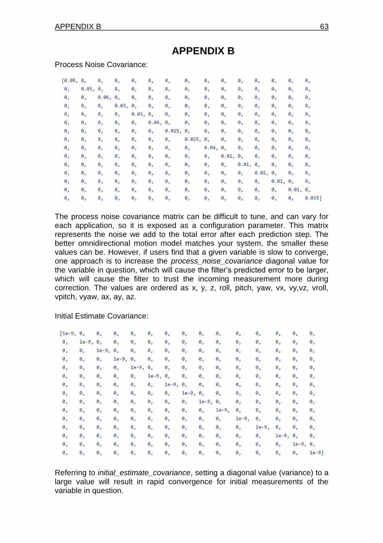
APPENDIX B 63
APPENDIX B
Process Noise Covariance:
The process noise covariance matrix can be difficult to tune, and can vary for each application, so it is exposed as a configuration parameter. This matrix represents the noise we add to the total error after each prediction step. The better omnidirectional motion model matches your system, the smaller these values can be. However, if users find that a given variable is slow to converge, one approach is to increase the process_noise_covariance diagonal value for the variable in question, which will cause the filter’s predicted error to be larger, which will cause the filter to trust the incoming measurement more during correction. The values are ordered as x, y, z, roll, pitch, yaw, vx, vy,vz, vroll, vpitch, vyaw, ax, ay, az.
Initial Estimate Covariance:
Referring to initial_estimate_covariance, setting a diagonal value (variance) to a large value will result in rapid convergence for initial measurements of the variable in question.

64 Autonomous Rover for Indoor Localization
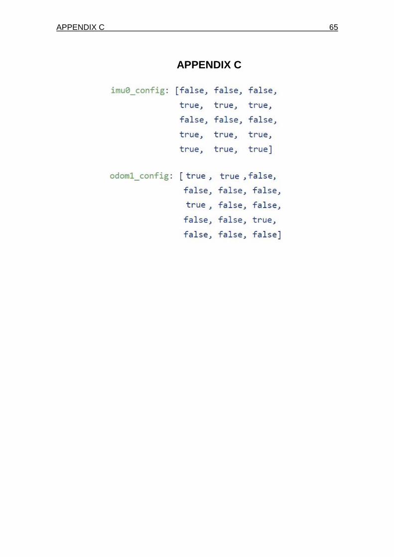
APPENDIX C 65
APPENDIX C