Embed Size (px)
Citation preview

T U MI N S T I T U T F U R I N F O R M A T I K
Using UML for Modelinga Distributed Java Application
Klaus BergnerAndreas Rausch
Marc Sihling
������TUM-I9735Juli 1997
T E C H N I S C H E U N I V E R S I TA T M U N C H E N
TUM-INFO-07-1997-I9735-350/1.-FIAlle Rechte vorbehaltenNachdruck auch auszugsweise verboten
c 1997 MATHEMATISCHES INSTITUT UNDINSTITUT F UR INFORMATIKTECHNISCHE UNIVERSITAT MUNCHEN
Typescript: ---
Druck: Mathematisches Institut undInstitut f¨ ur Informatik derTechnischen Universit¨ at M unchen

Using UML for Modeling
a Distributed Java Application�
Klaus Bergner, Andreas Rausch, Marc Sihling
Institut f�ur Informatik
Technische Universit�at M�unchen
D-80290 M�unchen
http://www4.informatik.tu-muenchen.de
30th July 1997
Abstract
The Uni�ed Modeling Language consists of a set of mostly graphical description tech-niques for the speci�cation and documentation of object-oriented systems. We describethe experiences gained while using UML 1.0 for the development of a small, distributedJava program for planning break supervision schedules in schools. Our motivation in thiscase study is not only to evaluate the techniques provided by UML and Java, but alsoto study their interrelationships and their methodical use from requirements analysis toimplementation. Based on our observations some proposals for extensions and changesto the UML are made. Because the example is complete and self-contained and providesmethodical guidelines and hints, it can also be used as a tutorial for UML 1.0 and forobject-oriented development in general.
Keywords: Object-Oriented Software Engineering, Modeling, Analysis, Design, UML,Java, RMI
�This paper originated in the ForSoft project A1 on \Component-Based Software Engineering" and was
supported by Siemens ZT.
1
Contents
1 Introduction 4
2 Techniques and Process 52.1 Uni�ed Modeling Language . . . . . . . . . . . . . . . . . . . . . . . . . . 52.2 Process . . . . . . . . . . . . . . . . . . . . . . . . . . . . . . . . . . . . . 62.3 Java, Object Serialization and Remote Method Invocation . . . . . . . . . 6
3 Initial Customer Speci�cation 73.1 Overview . . . . . . . . . . . . . . . . . . . . . . . . . . . . . . . . . . . . 73.2 Provided Documents . . . . . . . . . . . . . . . . . . . . . . . . . . . . . . 7
3.2.1 Non-Functional Requirements . . . . . . . . . . . . . . . . . . . . . 83.2.2 Scenario: Constructing a Break Supervision Plan . . . . . . . . . . 83.2.3 CRC-Cards . . . . . . . . . . . . . . . . . . . . . . . . . . . . . . . 93.2.4 System Vision: Constructing a Break Supervision Plan . . . . . . 10
4 Requirements Analysis and System Speci�cation 114.1 Use-Case-Driven Analysis . . . . . . . . . . . . . . . . . . . . . . . . . . . 11
4.1.1 Use Case Diagram . . . . . . . . . . . . . . . . . . . . . . . . . . . 114.1.2 Description of Use Cases . . . . . . . . . . . . . . . . . . . . . . . . 134.1.3 Description of Users . . . . . . . . . . . . . . . . . . . . . . . . . . 134.1.4 Use Case: Edit Break Plans . . . . . . . . . . . . . . . . . . . . . . 144.1.5 Use Case: Update Break Statistics . . . . . . . . . . . . . . . . . . . 164.1.6 Use Case: Manage Users . . . . . . . . . . . . . . . . . . . . . . . . 164.1.7 User Interface Prototype . . . . . . . . . . . . . . . . . . . . . . . . 18
4.2 Class-Driven Analysis . . . . . . . . . . . . . . . . . . . . . . . . . . . . . 194.2.1 Class Diagram . . . . . . . . . . . . . . . . . . . . . . . . . . . . . 194.2.2 Data Dictionary of Analysis Classes . . . . . . . . . . . . . . . . . 214.2.3 Class State Diagrams . . . . . . . . . . . . . . . . . . . . . . . . . 23
5 System Design 235.1 Business-Oriented Design . . . . . . . . . . . . . . . . . . . . . . . . . . . 24
5.1.1 Transforming the Analysis Class Diagram . . . . . . . . . . . . . . 245.1.2 User Interface Design . . . . . . . . . . . . . . . . . . . . . . . . . 255.1.3 Realization of Update on Change . . . . . . . . . . . . . . . . . . . 255.1.4 Management of Associations . . . . . . . . . . . . . . . . . . . . . 275.1.5 Break Con ict Detection . . . . . . . . . . . . . . . . . . . . . . . 295.1.6 Persistence Management . . . . . . . . . . . . . . . . . . . . . . . . 295.1.7 Data Dictionary of Business-Oriented Design Classes . . . . . . . . 30
5.2 Distribution Design . . . . . . . . . . . . . . . . . . . . . . . . . . . . . . . 335.2.1 Choice of Distribution Architecture . . . . . . . . . . . . . . . . . . 335.2.2 Realization with RMI . . . . . . . . . . . . . . . . . . . . . . . . . 35
6 Class Design and Implementation 386.1 Selection of Data Types . . . . . . . . . . . . . . . . . . . . . . . . . . . . 386.2 Implementation of Associations . . . . . . . . . . . . . . . . . . . . . . . . 406.3 Separation of Client and Server Functionality . . . . . . . . . . . . . . . . 406.4 Packaging of Java Source Code . . . . . . . . . . . . . . . . . . . . . . . . 416.5 Implementation of Method Bodies . . . . . . . . . . . . . . . . . . . . . . 41
2

7 Comments 417.1 Use Case Diagrams . . . . . . . . . . . . . . . . . . . . . . . . . . . . . . . 427.2 Class Diagrams . . . . . . . . . . . . . . . . . . . . . . . . . . . . . . . . . 447.3 Sequence Diagrams . . . . . . . . . . . . . . . . . . . . . . . . . . . . . . . 467.4 Collaboration Diagrams . . . . . . . . . . . . . . . . . . . . . . . . . . . . 477.5 State Diagrams . . . . . . . . . . . . . . . . . . . . . . . . . . . . . . . . . 477.6 Activity Diagrams . . . . . . . . . . . . . . . . . . . . . . . . . . . . . . . 487.7 Implementation Diagrams . . . . . . . . . . . . . . . . . . . . . . . . . . . 497.8 User Interface Prototype . . . . . . . . . . . . . . . . . . . . . . . . . . . . 507.9 Java, Object Serialization and Remote Method Invocation . . . . . . . . . 517.10 Tool Support . . . . . . . . . . . . . . . . . . . . . . . . . . . . . . . . . . 51
8 Conclusion 52
3

1 Introduction
The Uni�ed Modeling Language has been proposed by Grady Booch, Ivar Jacobson,and James Rumbaugh as a standard notation for object-oriented analysis and design[BRJ97]. UML version 1.0 incorporates variants of techniques from the successful methodsOOA/OOD [Boo94], OMT [RBP+91], and OOSE [Jac92] from the same authors, andadds some new contributions. Although most of the single techniques are in principle wellunderstood and widely used, at the current time neither a standardized \Uni�ed Method"nor case studies exist that show the methodical use of UML 1.0 as a whole.
Open questions are, for example, whether the techniques are su�cient for the descriptionof all important aspects of object-oriented systems, which relationships and consistencycriteria exist between them, and how they should be used and re�ned during the devel-opment process. While some answers to these problems can be found during the attemptto formalize the semantics of UML [BHH+97], other problems and answers can be foundmost easily by performing \real-world" case studies, which may also serve as a referencefor future developers.
Our case study is concerned with the development of a small, distributed system for usein schools where teachers have to be scheduled for the supervision of pupils during breaks(Section 3 contains the initial customer speci�cation). The system can be roughly cat-egorized as a graphical, distributed editor. It o�ers simple edit functions and requiresneither specialized algorithms nor complex transaction management. The example wasprovided originally in [RSLML96] for the evaluation of programming paradigms and toolsby the DACH group [DAC]. However, it is also a very suitable example for the evaluationof modeling languages because it is relatively small but still contains many di�erent as-pects: Among the requirements are the possibility of distributed usage, the managementof persistent data and the inclusion of a self-explanatory graphical user interface.
Our goal with this case study is not so much to examine the individual description tech-niques of UML but to concentrate on their interrelationships and their methodical use asa whole in the context of a complete and self-contained example. The most interestingaspects in this respect are the re�nement and transformation of abstract documents intomore concrete documents and �nally into Java code [Jav95], and, conversely, the in uenceof the design and implementation decisions and constraints on the UML documents.
Because the relatively detailed initial speci�cation of the schedule planner was providedusing CRC-Cards [WBWW90]|a formalism not contained in UML|we could start fromscratch and run through nearly the whole development cycle from analysis to implemen-tation. Maintenance and further development were not considered (we plan to examinethis issue in a future study).
Because it was our goal to study the relationships between the various description tech-niques of UML, we tried to apply each of them as recommended in [BRJ97], showing allits possible application areas. For this reason, some techniques serve di�erent purposes|like, for example, activity diagrams, which are used for business process modeling duringanalysis and also for modeling the control ow of single operations during design.
Another, sometimes con ictive goal was to avoid unnecessary complexity by modeling onlyimportant aspects of the application and by con�ning ourselves to the basic features ofeach description technique. We think that the resulting speci�cation and implementationdocuments are nevertheless reasonable and realistic also for an industrial setting.
4

The paper has the following structure: Section 2 provides a very short introduction to theUML techniques, the process we followed, and the Java techniques we used. The followingfour sections correspond to the phases of our development process|initial customer spec-i�cation, requirements analysis and system speci�cation, system design, and class designand implementation. They contain the development documents of the break planner sys-tem and describe our considerations, experiences and observations during development.Section 7 gives our comments on the description techniques of UML and makes somesuggestions for enhancements. A short conclusion summarizes the results of the paper.
2 Techniques and Process
2.1 Uni�ed Modeling Language
Besides some common structuring mechanisms and base features like, for example, apackage mechanism for the organization of the development documents and a notationfor annotations of all kinds of model elements, UML provides description techniques forvarious aspects of a system:
Static Structure Diagrams model the data aspect of an object-oriented system, andcan also contain information about the functionality of the data items. Static struc-ture diagrams exist in two variants: Class diagrams show the classes of the pro-gram code, their attributes and operations, and the relationships and dependenciesbetween them. Object diagrams show graphs of object instances that may ariseduring runtime of a system. Class diagrams may be seen as a special kind of E/R-diagrams [Che76] and are very common in object-oriented development methods[SM88, RBP+91, Boo94, CAB+94]. They are used for data modeling in the earlydevelopment phases and are later re�ned and enriched with additional attributesand operations. Finally they can be translated into class skeletons.
Use Case Diagrams model the users and their interactions with the system at a veryhigh level of abstraction. They serve as a structuring tool for more concrete descrip-tions of a system's functionality like, for example, sequence diagrams.
Sequence Diagrams , also known as message sequence charts [IT93, LRH97] or ex-tended event traces [SHB96, BHKS97], show example communication histories be-tween users or objects. The UML variant is extended with constructs for the creationand deletion of objects as well as for synchronous and asynchronous communication.
Collaboration Diagrams are a special form of object diagrams enriched with infor-mation about the message ow between the objects and about object creation anddeletion. Although the graphical syntax of collaboration diagrams is di�erent fromsequence diagrams, they represent nearly the same information. The main di�erenceis that sequence diagrams have their focus on the temporal order of events, whereascollaboration diagrams concentrate on the relations and connections between ob-jects.
Class State Diagrams can be used to model the data state and its changes during thelifecycle of the objects of a certain class. The data state of an object consists of theactual attribute values of the object, its references to other objects, and possiblyalso the data states of referenced objects. A special notation is provided for statetransitions that trigger the sending of messages to other objects.
5

Activity Diagrams are a special kind of state transition diagrams used to specify controlstate. They can be used on di�erent abstraction levels for business process modelingof user interactions as well as for modeling the control ow of single operations.
Implementation Diagrams exist in two variants. Component diagrams show the struc-ture of the source code and its partitioning into components, and deployment dia-grams show the run-time implementation structure and the distribution of objectsand components on physical computing nodes.
2.2 Process
For reasons of clarity, we have chosen to structure the development documentation ac-cording to the phases of a typical waterfall model. Our actual process was not so linearbecause there were some feedback loops between the phases, and because we were usingprototyping to develop the user interface of the program. This �ts well with the ideas ofthe UML developers, who promote a \use-case driven, architecture-centric, and iterativeand incremental process" [BRJ97].
Our \idealized" process consists of the following phases:
Requirements Analysis and System Speci�cation (see Section 4) is concerned withissues important not only for programmers, but also for customers and users of thesystem. The central documents are a use case diagram and a class diagram towhich other diagrams for modeling dynamic aspects and user interface prototypesare added.
System Design (see Section 5) is concerned with the development of an abstract tech-nical solution that is independent from a certain implementation language or frame-work. We splitted this phase further into two sub-phases, following the principle\Architecture �rst|distribute later." (cf. [SCB95]):
During business-oriented design (see Section 5.1), additional design classes are added,and the decisions about the operations and attributes, the intended object graphsat runtime, and the ow of control and data are made. During distribution design(see Section 5.2), the distribution of the objects on physical computation nodes andthe communication protocols to be used are determined.
Class Design (see Section 6) is concerned with the re�nement of the system design tocomplete class signatures usable as skeletons for the implementation in a certainlanguage. We also delayed the selection of Java datatypes for attributes and methodparameters and the decision how to implement the associations and aggregationrelationships until this phase.
Implementation (see Section 6) provides the method bodies to the class signaturesde�ned during class design.
The role of prototyping is explained in more detail in Section 7.
2.3 Java, Object Serialization and Remote Method Invoca-
tion
The Java language framework was �rst presented by SUN in 1995 and has since beencontinuously developed further. With version 1.1 of the Java Development Kit [SUN97b],
6

various enhancements have been introduced, especially in the area of the graphical userinterface framework AWT. Other new features are object serialization and an object-oriented remote procedure call facility named Remote Method Invocation, or just RMI[SUN97c].
Object serialization o�ers a mechanism to store an object together with all of its referencedobjects to a stream of bytes and to safely restore the object from the byte-stream later.By mapping the stream to a �le it is very easy to store object graphs persistently.
RMI allows the communication between objects in di�erent processes and address spaces,possibly on di�erent hosts. As soon as a Java program gets a reference to a remoteobject|either via parameter passing or via a special bootstrap-naming service|it cansend method calls to this object in a transparent way. The RMI mechanism takes care ofmarshaling and unmarshaling parameter objects using object serialization.
RMI and object serialization are tightly integrated into the Java framework and extendJava features like garbage collection and dynamic binding to support distributed program-ming.
3 Initial Customer Speci�cation
3.1 Overview
As mentioned in the introduction, the speci�cation of the DACH group is geared towardsthe evaluation of programming paradigms and programming tools. It is thus neitherunambiguous nor complete|a situation common also for real-world speci�cations. In thefollowing we will pretend that the speci�cation was given to us by a \real" customer.
According to the customer speci�cation, the application scenario is as follows: Teachershave to supervise pupils in the various parts of a school building during the breaks. Theassignment of teachers to breaks is speci�ed in the break plan of the respective buildingpart. Each break must be supervised by a teacher, and teachers are assigned to breaksdepending on the time they spend for teaching|a full-time teacher has to supervise morebreaks than a teacher with only a couple of lessons per week. Teachers can provide theschool with time periods during which they can not be assigned to breaks because of otherduties.
The intended system supports the persons responsible for maintaining the break plans andthe teaching sta� data (from now on they are called \plan editors" and \sta� editors",respectively). It allows the user for example to create and to delete break plans, to assignteachers to breaks, and to manage a list of the school's teachers. Additionally, the toolcomputes some statistical values for plan editors, for example the number of breaks ateacher still needs to be assigned to.
3.2 Provided Documents
The given speci�cation comprises:
� A set of (very unspeci�c) non-functional requirements (see Section 3.2.1).
� An informal usage scenario (see Section 3.2.2).
7

� Class-Reponsibility-Collaboration cards of the break planner system's classes (seeSection 3.2.3). CRC-cards are proposed as a formalism for requirements analysisand system design in [WBWW90]. For each class, a CRC-card contains (below theClass name) on the left side the Responsibilities of the class, and on the right sidethe Collaborations with other classes needed to ful�ll its responsibilities.
� A so-called \system vision", which consists of a short, informal description and apicture of the intended GUI and its usage (see Section 3.2.4).
While all customer documents were provided in German, we have included a completetranslation into English with permission of the DACH group. To distinguish the customerdocuments from the rest of the text, they are printed in a seri ess font.
During the modeling and development of the break planner, the customer speci�cationwas treated more as a suggestion than as a strict prescription on how to build the appli-cation. This is mostly due to the fact that the CRC-cards of the DACH group anticipatesome decisions that should be delayed until the design phase: Their responsibilities aretoo detailed and correspond to single operations|not, as proposed in [WBWW90], togroups of operations and attributes belonging together. Used in this more abstract way,responsibilities are a good way to structure the operations of a class (see Section 7.2).
3.2.1 Non-Functional Requirements
� Distribution (more exactly: distributed usage)
� Persistent data management
� The system must be self-describing.
� The target systems must be PC/Windows or UNIX.
Hint: The user interface may use Drag-&-Drop.
3.2.2 Scenario: Constructing a Break Supervision Plan
For each teacher, the user of the program has a pile of teacher cards with the teacher's nameon it. Beneath the name, the cards contain the breaks that cannot be supervised by therespective teacher (also known as exclusion times).
The cards are iteratively placed on the initially empty break supervision plan until each breakis occupied by exactly one teacher. If the user wants, he or she may move or remove cards onthe plan.
Each time a teacher is assigned to a break, the break statistics is updated. The break statisticsenables the user to see how many breaks each teacher has to supervise and also his percentalshare of the total breaks. This way half-time and three-quarter-time jobs can be handled.
8

3.2.3 CRC-Cards
Break Planner
accept a new break plan to work on it break plan�ll the break plan and update the break statistics break statisticsreturn break plan sta�return statistics breakmake sure that all breaks are supervised, that con ictsin the assignment of the breaks are minimized, and thatthe supervision assignments of the teachers correspondto their job sharesdetermine teaching sta�assign exclusion time to a teacher
Break Plan
initialize / clear plan teacherassign a teacher to a break breakcheck whether a teacher can supervise a breakremove teacher from breakcheck whether all breaks are supervisedreturn unsupervised breaksreturn the breaks that are supervised by a teacherreturn teacher supervising a breakcheck whether con icts existreturn all breaks with con icts
Break Statistics
reset all supervision counters teacherincrement supervision counter for teacher sta�return supervision counter for a teacherreturn number of supervision duties for a teacherset number of breaksreturn number of breaksreturn all teachers with free capacity
Sta�
add a teacher teacherremove a teachernumber of teachersenumerate the teachers
Break
enter time period teacherreturn time period time periodassign to a teacherremove teachercheck whether occupiedcheck whether assignment has a con ict
9

Teacher
enter name time periodreturn nameenter job sharereturn job shareenter exclusion timeremove exclusion timecheck whether teacher can supervise a time period
Time Period
enter day of the week, start time, and end timecheck whether time period overlaps with another timeperiod
3.2.4 System Vision: Constructing a Break Supervision Plan
Figure 1 shows a picture of the intended user interface of the break planner application.
Figure 1: System Vision
On the left side of the tool the teacher cards are displayed. They can be placed on the cells ofthe break plan to the right via drag-&-drop. Whenever a teacher card is taken from the stack,the status line shows the breaks that can not be supervised by the teacher. It is neverthelesspossible to place a card on such a break. Con icts have to be highlighted in red color.Already placed cards may be re-placed via drag-&-drop. Assignments on the plan that areto be removed must �rst be selected and are then removed by pressing the `Remove' button.The actual break plan can be printed by pressing the `Print' button. The button `New Plan'clears the complete actual break plan. The second status line shows the supervision dutiesand the number of already assigned breaks for the actual teacher card.
10

4 Requirements Analysis and System Speci�ca-
tion
During requirements analysis and system speci�cation, a common understanding of thesystem's functionality must be established between customers and developers. Descrip-tion techniques must, therefore, be simple and understandable also by persons with noexperience in object-oriented modeling.
Hence, our basic strategy for analysis was to build two central, high-level models to whichother more concrete and complex supplementary diagrams are added. This way, noviceand experienced customers can start with common, easily understandable base techniquesand proceed to more detailed descriptions only if required.
� The use case model shows the users and uses of the whole system. Use cases withnontrivial dynamic behavior are speci�ed further with the help of activity diagrams,sequence diagrams and user interface prototypes.Use case models are usually easy to understand for customers because they haveno complex syntax and concern tasks and processes with which the intended usersare familiar from their everyday work. The corresponding sequence diagrams andactivity diagrams make it easy to do a step-by-step simulation of a system's dynamicsand thus allow a customer to gradually derive a global understanding from localinsights.
� The class diagram shows the data items that were identi�ed in the use case modeland contains operations that can be applied to these items. Analogously to the usecase diagram, dynamic aspects of classes with a nontrivial life cycle are speci�edfurther with the help of class state diagrams.Class diagrams are usually reviewed by customers, but experience shows that theyare more di�cult to understand than use cases.
The system's operations were speci�ed only with informal text in the data dictionary of theanalysis class diagram (see section 4.2.2). In the case of the break planner application thisseems adequate because the operations have no complex before- and afterconditions andtheir behavior is rather trivial|most of them concern simple updates of data attributesor association links.
4.1 Use-Case-Driven Analysis
4.1.1 Use Case Diagram
While the customer speci�cation is quite detailed with respect to the CRC-Cards, theattempt to create a use case diagram shows that some basic information is only implicitor even missing.
The basic use cases of the system could be easily identi�ed (see Figure 2 and Section 4.1.2):The central use case is of course Edit Break Plan|it contains functionality for assigningteachers to breaks as described in the given customer scenario (see Section 3.2.2). Wedecided to model this use case as an extension of Manage Break Plans, which covers thefunctionality concerning whole break plans (like creation and deletion of empty plans,printing, and persistence management), because creation, opening, and closing of a break
11

plan are necessary prerequisites for editing, but can also be performed independently (fora discussion of the semantics of use case diagrams and their relationships cf. sections 7.1and 7.3).
The third basic use case is Manage Teachers, which contains functionality for adding andremoving teachers and for changing their data.
Plan Editor
Edit Break Plans
Maintain Break Statistics
Manage Teachers
Manage Break Plans
<<uses>>
<<uses>>
<<uses>>
System Administrator
Manage Users
Staff Editor
<<extends>>
Figure 2: Use Case Diagram
We provided a separate use case Maintain Break Statistics for updating the values of thebreak statistics and for presenting them to the user because this functionality is requiredfor Edit Break Plan, Manage Teachers, and Manage Break Plans.
While the �rst four use cases could be derived from the customer speci�cation (mainlyfrom the usage scenario and the given responsibilities of the CRC-class BreakPlanner whichrepresents the whole system), a �fth use case was introduced based on our understandingof the problem: Because a school's computer network is a particularly unsafe environment(consider, for instance, intrusion attempts by pupils), some sort of access control andaccount management is needed for the system. This functionality is covered by ManageUsers. We decided not to include use cases for backing up the system's data and forstarting and shutting down the system because these activities are outside the system'sscope and do not pertain to the services it provides.
Information about the users of the system is not given explicitly (besides the crypticrequirement of \distributed usage"). According to our interpretation, there exist threekinds of users: Plan editors and sta� editors work with the system, whereas the systemadministrator is concerned with the management of user accounts (see section 4.1.3).
In addition to the UML use case diagram in Figure 2, we have included a use case dic-tionary with information about the frequency of execution, the corresponding data, andthe intended security level of a use case (see Section 4.1.2), as well as about the number,
12

experience level, and location of users (see Section 4.1.3). The entries in the use case anduser descriptions are mainly based on our interpretation of the customer speci�cation;they serve as informal clues for the subsequent phases. For special application areas onewould of course need more detailed speci�cations, like, for example, exact de�nitions ofsecurity measures.
The use case dictionary and its format are not contained in [BRJ97], but have beendeveloped specially for the description of the break planner application.
4.1.2 Description of Use Cases
Manage Break Plans Handle break plans as a whole. This includes creation and deletion,opening and closing, and printing of break plans as a whole.
Frequency: weekly to daily during terms
Data: BreakPlan
Security: medium
Edit Break Plans Assign teachers to breaks as described in the usage scenario of Section3.2.2.
Frequency: weekly to daily during the terms
Data: BreakPlan, Period, Break, Sta�, Teacher
Security: medium
Manage Teachers Add and remove teachers from the sta� and change their attributes.
Frequency: monthly to weekly
Data: Sta�, Teacher
Security: medium
Maintain Break Statistics Update the break statistics and present it to the user.
Frequency: triggered by changes of break plans
Data: Statistics, Sta�, Teacher
Security: low
Manage Users Manage the accounts of the break planner system.
Frequency: yearly to monthly
Data: Account
Security: high
Note that it is no contradiction that the low-security use case Maintain Break Statisticsis used by the medium-security use case Manage Break Plans: Even if somebody may getaccess to the break statistics by some means, one can not automatically assume that heor she can also change break plan data in the system.
4.1.3 Description of Users
Plan Editor The break planner system is used by the employees of a single school (amongwhich may be some or all of its teachers). Some employees may work on break plansfor di�erent parts of a school building at the same time. A break plan can only beworked on by a single plan editor. All plan editors have the same edit permissions.
13

Number: usually less than ten
Experience: novice to advanced users
Location: normally inside the school building, but users may also work at homeover the internet with a Java-capable browser
Sta� Editor The teaching sta� of the school is maintained normally by a single dedicatedemployee. This person has to deal with sensitive data (e.g. the supervision duties ofthe teachers) and thus needs a a special edit permission.
Number: usually only one or two members of the personnel o�ce
Experience: advanced users
Location: inside the school's personnel o�ce
System Administrator This person is responsible for the management of the user ac-counts.
Number: normally one person
Experience: expert user
Location: in his or her o�ce in the school
4.1.4 Use Case: Edit Break Plans
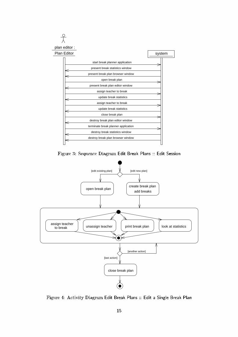
Explicit information about interaction scenarios of the intended system is given in Sections3.2.2 and 3.2.4 of the initial customer speci�cation. This information pertains mainly tothe user interface and can, therefore, be demonstrated best with a prototype of the userinterface (see Section 4.1.7). Moreover, most of the dynamic behavior is self-evident inthe context of an interactive editor like the break planner system where the user is freeto perform most actions whenever he or she wants to. The use of special descriptiontechniques for the system's dynamics is, therefore, hardly necessary in our case. We havenevertheless included sequence and activity diagrams to demonstrate the use of UML'smodeling techniques for the description of user interactions.
The sequence diagram of Figure 3 shows a possible exemplary action sequence named EditSession assigned to the use case Edit Break Plans: A plan editor starts the break plannerapplication, chooses a break plan to edit and assigns two teachers to breaks before theapplication is �nally terminated. The system maintains a window with the actual breakstatistics during the whole session.
Sequence diagrams can only describe exemplary action sequences|they do not specify therequired behavior of a user or the system exhaustively. To restrict the possible interactionsof a certain use case (or \business process") during system analysis, UML o�ers activitydiagrams. Figure 4 prescribes the work ow of a single user editing a break plan: He orshe must �rst decide whether an existing break plan shall be opened or a new plan shallbe created. After doing so, he or she can repeatedly assign teachers to breaks, unassignteachers from breaks, print the plan, or look at the maintained statistics. Finally, thebreak plan has to be closed.
To be consistent with the corresponding sequence diagrams, each sequence must be con-sistent with the execution of the corresponding activity diagram's state automaton. Ascan be seen from a comparison of Figures 3 and 4, this is true for our diagrams: As faras actions from the activity diagram are concerned, the sequence diagram can be seen asa trace of the activity diagram's state machine.
14
plan editor :
system
start break planner application
present break plan browser window
open break plan
assign teacher to break
update break statistics
assign teacher to break
update break statistics
destroy break plan editor window
present break plan editor window
terminate break planner application
present break statistics window
destroy break statistics window
destroy break plan browser window
close break plan
Plan Editor
Figure 3: Sequence Diagram Edit Break Plans :: Edit Session
close break plan
[edit existing plan] [edit new plan]
add breaks
create break plan
[another action]
[last action]
open break plan
assign teacherto break print break planunassign teacher look at statistics
Figure 4: Activity Diagram Edit Break Plans :: Edit a Single Break Plan
15

4.1.5 Use Case: Update Break Statistics
While the interactions during Edit Break Plan could be in principle demonstrated withthe help of a user interface prototype, there is another feature|namely, Maintain BreakStatistics in the context of more than one user|that can not be simulated easily by aprototype because it requires the realization of most of the application's functionality.The scenario in 3.2.2 says that \each time a teacher is assigned to a break, the breakstatistics is updated". A similar principle applies to the presentation of break plans:Whenever a break assignment con icts with another one, its representation in the userinterface should be updated to be visually distinguishable. The handling of updates couldbe implemented in various ways:
Update on Request: Users have to press an update button to request a window withan actual version of the break statistics.
Interval Updates: The break statistics window is updated automatically in distincttime intervals.
Update on Change: The break statistics window is updated whenever a break planchanges. Hence changes of one user are immediately visible to other users.
Of these variants, the third seems to follow the customer speci�cation most closely andis, therefore, added to the requirements. However, we have also considered the other twopossibilities because they lead to much simpler implementations and enable some con�g-urations that are not possible with the third variant (see the section about bidirectionalcommunication in Section 5.2.2 on page 38).
Each variant is associated with a di�erent sequence diagram, as shown in Figure 5, wherethe interactions between three users and the system are modeled. In contrast to thediagram of Figure 3, these diagrams are not directly assigned to a certain use case becausethey concern all use cases that have a �uses�-connection to Maintain Break Statistics: Thechange events in the sequence diagram arise during the execution of the use cases ManageTeachers, Edit Break Plan, and Manage Break Plans, whereas the update events belong tothe use case Maintain Break Statistics.
4.1.6 Use Case: Manage Users
Activity diagrams can be very useful to show the embedding of the system's work owsinto its organizational environment. Later on, these informations could be used to writedocumentation and a user's guide for the application. We have added an activity diagramfor the Add User activity of the use case Manage Users to demonstrate this (see Figure6): In order to perform actions concerning the access to the break planner program, someorganizational actions have to be performed as well. The following description of theactivity diagram explains this informally.
Manage Users :: Add User The system administrator adds a user to the system andprovides him or her with a password. Users can be sta� editors as well as planeditors.To gain access to the system, each user has to read and sign a special form providedby the school (the system administrator may hand out the password only if a signedform for the user has been �led).
16

Plan Editor
plan editor 1 :
Plan Editor
plan editor 2 : staff editor 1 :
Staff Editor
Plan Editor
plan editor 1 :
Plan Editor
plan editor 2 : staff editor 1 :
Staff Editor
Plan Editor
plan editor 1 :
Staff Editor
update
update request
change
update request
update
system
a
b
c
d
e
f
update
update
update
update
update
update
change
{d - a = 5 sec}
{e - b = 5 sec}
{f - c = 5 sec}
system
update
change
update
updateupdate
update
change
update
system
Interval Update
Update on Change
Update on Request
Plan Editor
plan editor 2 : staff editor 1 :
Figure 5: Possibilities for Update of the Break Statistics
17

The action states add new account and allow remote internet access contain the onlyactions a�ecting the computer system to be realized. All other actions are outside ofthe system boundary and must be performed manually by the system administrator.
Figure 6 shows the corresponding activity diagram. In contrast to the activity diagramin the previous section it involves two users.
password
System Administrator User
prepare formadd newaccount
sign form
file form
memorizepassword
password
form[signed]
form[empty]
[remoteaccess
requested]
receive requestfor new account
allow remoteinternet access
access[no remote
requested]
hand out
Figure 6: Activity Diagram Manage Users :: Add User
4.1.7 User Interface Prototype
A prototype is a good way to ensure that developers and customers share the same un-derstanding of the system. Normally it is a quickly implemented program demonstratingsome aspects of the system, for example parts of the GUI layout and some of the possibleinteractions between the user and the system. A prototype of this kind can be assignedto one or more concerned use cases. It serves as an additional, very intuitive tool forthe description of the system's externally visible dynamic behavior and can often replacesequence and activity diagrams.
18

A �rst, paper-based prototype of the user interface for plan editors is already providedwithin the system vision of the customer speci�cation. However, it gives only a veryrough impression and can not replace a computer-based prototype because its layout doesnot conform with the �nal tool and its dynamic behavior cannot be demonstrated to acustomer.
The development of the prototype on the Windows platform was performed by KlausBerg and Briktius Marek, our industrial partners at Siemens ZT. They used the JavaDevelopment Kit Version 1.0.2 as described in [Fla96] and Symantec's Caf�e DevelopmentEnvironment for programming. In contrast to the successor tool Visual Caf�e [Sym97], Caf�ehas no integrated visual GUI builder, so the user interface was programmed manually. Wehope that the experience gained with this minimalistic approach will help us with a laterevaluation of di�erent user interface tools and techniques.
The prototype includes only some parts of the system's user interface: Due to time con-straints, the parts for the presentation of the break statistics and for system administrationwere not created. The concerned use cases are, therefore, only Manage Break Plans, EditBreak Plans, and Manage Teachers. Furthermore, the language of the GUI is German, asstated in the original speci�cation of the DACH group. Figure 7 shows a screen shot ofthe prototype. The prototype itself can be downloaded via [BM97].
Figure 7: GUI Prototype for the Breakplanner Application
4.2 Class-Driven Analysis
4.2.1 Class Diagram
The analysis class diagram in Figure 8 contains the classes from the CRC-cards of Section3.2.3 (with the Break Planner renamed to Organizer, to avoid confusion with the intendedapplication). Apart from that, two additional classes have been introduced:
19

3HULRG
GD\EHJLQHQG
RYHUODSV� �
�
���
([FOXVLRQ7LPH
��� ����
�
���
7HDFKHU
QDPHMRE
QHHGHG'XWLHV� �
�
���
�
6WDWLVWLFV
FDOFXODWH� �FRXQW%UHDNV� �FRXQW-REV� �
��6LQJOHWRQ!!
�
�
�6WDII
VFKRRO
��6LQJOHWRQ!!
�
���
��
�
���
%UHDN
KDV&RQIOLFW� ���� ����
VXSHUYLVHV
�
2UJDQL]HU
��6LQJOHWRQ!!
�
�
���
%UHDN3ODQ
SODFH
�
���
�
���
RUJDQL]HV
$FFRXQW
QDPHSDVVZRUGNLQG
Figure 8: Analysis Class Diagram
20

� Account is responsible for the handling of the user accounts necessary to log into thesystem.
� ExclusionTime models a weekly recurring period of time during which a certainteacher can not be assigned to a break. We explicitly allow exclusion times like\whole Tuesday" or \Wednesday, from 10:00 to 14:00".
To express that a class must have exactly one object instance at runtime, we have intro-duced the �Singleton� stereotype for the classes Organizer and Sta�. In the context ofthe break planner, this models the implicitly given requirement that the break plannerapplication is used in a single school with a single teaching sta�. Statistics is also a single-ton because it represents the conceptually unique statistical values for the actual teachingsta� con�guration, not a sheet of paper with a statistics on it.
Compared to the responsibilities on the CRC-cards, the classes in the diagram of Figure8 contain much fewer entries. This has the following reasons:
� Some pairs of responsibilities were transformed into attributes. An example is thepair enter name/return name of the CRC-card Teacher, which was transformed to theattribute name of class Teacher.
� Some responsibilites are covered by associations. A typical case are the four re-sponsibilities assign a teacher to a break, remove teacher from break, return teachersupervising a break, and return the breaks supervised by a teacher of the CRC-cardBreak Plan. They have been transformed to the association supervises between theclasses Teacher and Break. The information that Break Plan instances are respon-sible for managing the links between Teacher and Break objects is omitted duringthis transformation|we think that this decision should be delayed until the designphase.
4.2.2 Data Dictionary of Analysis Classes
This section contains the data dictionary for each class found in Figure 8. We did neitherinclude information about the datatypes of the attributes nor about the signatures of themethods because this is part of the design process. Also, associations are left out as theycan be seen best in the class diagram.
Account A user account.
Attributes
name A user's name.
password A user's password.
kind Indicates whether the account belongs to a plan editor or a sta� editor.
Break A break to be supervised by a teacher. Each break has the same weight withrespect to a teacher's supervision duties.
inherits from Period
Operations
hasCon ict() Indicates that the assigned teacher is assigned to another breakat the same time or that the break overlaps with one of his or her exclusiontimes.
21

BreakPlan A collection of the breaks to be supervised by teachers in a certain part ofthe school building. The breaks of a break plan must not overlap.
Attributes
place The name of the school's building part where the supervising teachers arepositioned.
ExclusionTime A period of time during which the corresponding teacher cannot superviseany breaks.
inherits from Period
Organizer The organizer manages a collection of breaks plans. There exists exactly oneorganizer instance.
Period A weekly recurring period of time during a single day.
Attributes
day The day of the week of the period.
begin The start time of the period.
end The end time of the period.
Operations
overlaps() Determine whether two periods of time overlap.
Sta� The teaching sta� of the school for which the breaks are planned. There existsexactly one sta� instance.
Attributes
school A name identifying the school of the teaching sta�.
Statistics The statistics is calculated for the organizer and shows how many breaks eachteacher supervises already, how many breaks he or she has to supervise, and howmany breaks to be supervised as well as job shares exist. There exists exactly onestatistics instance.
Operations
calculate() Compute the values for the statistics.
countBreaks() Count the total number of breaks of all break plans of the orga-nizer.
countJobs() Count the total number of jobs of all teachers (for an explanationof jobs see the job attribute of class Teacher).
Teacher A teacher who has to supervise breaks.
Attributes
name The name of the teacher.
job The percentage of the teacher's part time job compared to a full-time job.
Operations
neededDuties() The number of breaks a teacher has to supervise, based on thetotal number of breaks and the number of available teachers, weighted ac-cording to their job share. If the resulting number is a fraction, the planeditor has to decide whether it should be rounded up or rounded down.
22

4.2.3 Class State Diagrams
The data items of the break planner application do not have complicated life cycles: Theirattributes can be changed at will during their lifetime and do not obey time-dependentstate invariants. Therefore, we decided to include only one class state diagram to expressthe information about the possibilities for invalid break assignments of a teacher:
Possible Supervision Assigment Con icts:
Exclusion Overlap Teacher assigned to break overlapping with one of his or her ex-clusion times.
Too Many / Too Few Duties Number of teacher's break assignments is too large ortoo small for his or her supervision duty.
Break Con ict Teacher assigned to two breaks at the same time on di�erent breakplans.
The corresponding class state diagram for the class Teacher is shown in Figure 9. Theevents addDuty and removeDuty correspond to the creation and deletion of supervises-associations between a Teacher and a Break in the class diagram in Figure 8.
removeDuty
[no overlap]addDutyaddDuty [overlap]
addDuty
removeDuty
addDuty
[overlap]
removeDutyaddDuty removeDuty [no conflict]
removeDuty [no overlap]
addDuty [conflict] [no conflict]addDuty
[conflict]removeDuty
break
conflict
exclusion
overlap
no
overlap
no
conflict
removeDuty
addDuty [proper]
[proper]
[toofew]
[proper]removeDuty
addDuty[too many]
[too few]
removeDuty
addDuty[proper]
removeDuty [proper]
proper
duties
duties
too few
duties
too many
addDuty [too few]
removeDuty[too many]
Figure 9: State Diagram for Class Teacher
Exclusion overlaps and break con icts must be visualized to the user in the break plan, forexample by using special graphical symbols or colors to display con icting or overlappingbreaks. Similarly, teachers with con icts or too many/too few duties could be visualizedin the break statistics.
5 System Design
Our strategy during this phase was to design the business-oriented data and functional-ity of the system before determining its distribution architecture. Apart from providingadditional structure for the development documents, this has the advantage that manybasic design decisions can be met without getting involved with the complexities of theunderlying distribution architecture. Because functional and non-functional aspects are
23

clearly separated, the functional design is more or less independent from the technical as-pects of a certain distribution architecture, simplifying the transition to other distributionarchitectures.
5.1 Business-Oriented Design
The essential step during business-oriented design is to construct a more detailed, re�nedand implementation-oriented class diagram from the analysis class diagram. The otherdescription techniques are mainly used to show certain views onto this class model or tospecify the dynamic behavior of its classes and operations. Setting the design focus onthe classes of the system makes the transition to the �nal implementation easier becauseclasses are the prevalent structuring construct of object-oriented program code.
Building the business-oriented design class model involves the following development ac-tions:
1. Some analysis classes can be adopted for system design without changing their name,functionality, or attributes.
2. Analysis classes can be dropped because they denote concepts not implemented bymeans of classes in the �nal system.
3. Analysis classes can be merged together or be split up. This can be done for variousreasons, for example to optimize access paths, to cache data for safety reasons, orto re�ne complex analysis classes.
4. New classes, attributes, and operations necessary for modeling technical concepts ofthe intended implementation can be introduced.
In our case, almost all classes from the analysis class diagram of Figure 8 have beenadopted in the business-oriented design class diagram given in Figure 10. Only Accounthas been dropped, and the functionality of Statistics has been split up to other classes.Finally, Observer and the whole package breakplanner.client have been introduced to modelthe integration of the user interface and to implement the Update on Change policy for thebreak statistics (see Section 4.1.5). All of these changes are described in detail in Sections5.1.1 to 5.1.6. Finally, Section 5.1.7 contains a data dictionary of all business-orienteddesign classes.
5.1.1 Transforming the Analysis Class Diagram
Account is not contained in the business-oriented design class diagram of Figure 10 becauseour intended implementation platform provides already suitable account and authorizationmechanisms, e.g. http logins and �le access modes. As a consequence, the implementationof an own account mechanism is unnecessary, and the use case Manage Users and the classAccount fall outside the system boundary of the intended program.
Statistics was also not adopted. The reason for this is that Statistics is rather a collectionof special-purpose functions than a \normal" class: It has neither attributes nor does itparticipate in non-trivial associations and is thus not used to hold data. Instead, the classcomputes certain values from the attributes of the other classes (see the description of theclass in the data dictionary in Section 4.2.2). During design it is a common problem how
24

to handle such special-purpose functionality. In general there are two ways to solve thisproblem:
� The architect can design a synthetic class responsible for the functionality. Theadvantage of this approach is that the centralized, \compact" representation of thefunctionality can be easily understood and used by other programmers. The disad-vantage is that the synthetic class needs references to most of the other classes andtheir associations and is, therefore, very fragile with respect to changes of these.
� The architect can split the functions among the di�erent classes they naturally be-long to, resulting in a simple and straightforward design. The disadvantage is thatfunctionality belonging together is now scattered over several classes, obfuscatingthe access from outside.
Although clear rules cannot be established, experience indicates that usually the secondsolution should be preferred, at least if it does not result in a plethora of operationsobfuscating the real purpose of the classes. For this reason we decided to distributethe analysis functions for the calculation of statistics to other classes (see Figure 10):countBreaks was assigned to Organizer, countJobs was assigned to Sta� , and calculate wasintegrated into the update method of the newly introduced GUI class StatisticsView (seeSection 5.1.2).
5.1.2 User Interface Design
The analysis class diagram does not specify how multiple users of the system can access thesystem's data at the same time. A technical solution to this problem is the introductionof view classes responsible for the presentation and manipulation of the data. The newsub-package breakplanner.client in Figure 10 is intended to contain all of these view classesfor the break planner application's GUI.
Although there exist many di�erent view classes for the presentation of the di�erent dataentities of the break planner, we have modeled only two exemplary classes: The Statis-ticsView controls a window with the statistics data, and the BreakPlannerView representsthe main window of the break planner application. We think that the decision to leave outmost of the view classes is reasonable because these view classes can be \modeled" andimplemented easily with the help of an interactive GUI tool. Yet, we wanted to include atleast one of the view classes into our design because it is needed to model the interactionbetween the application's GUI and the system core (for a detailed explanation see Section5.1.3). Another reason for the inclusion of StatisticsView is that it contains some of theapplication's functionality, namely the update method which is responsible for calculatingthe statistics.
5.1.3 Realization of Update on Change
An advanced requirement for the break planner application is the immediate update ofthe user interfaces. Each time a user changes a data value, the break statistics has to beupdated. The same principle applies to the visualization of con icting break assignmentsaccording to Section 4.1.5. To realize this Update on Change policy, we have used theso-called \observer pattern" (see [GHJV95] for details).
25

Observer
Observable
Observer
Figu
re10:
Busin
ess-Orien
tedDesign
Class
Diagram
26

The collaboration diagram of Figure 11 shows the dynamic behavior of the observer pat-tern: Observer objects register at the Observable objects they are interested in by callingthe latter's addObserver() method; unregistering is done via calling deleteObserver(). Eachtime a user changes an Observable's data, the Observable calls the update() method of eachregistered Observer. The called Observer can then react on the change of the Observable,for example by requesting the modi�ed data from the Observable.
REVHUYHU � 2EVHUYHUREVHUYDEOH � 2EVHUYDEOH
^WULJJHUHG E\ 2EVHUYHU FUHDWLRQ UHVS� GHOHWLRQ`
VHW&KDQJHG � �QRWLI\2EVHUYHUV � �
XVHU � 8VHU
DGG2EVHUYHU � �GHOHWH2EVHUYHU � �
XSGDWH � �
FKDQJH GDWD
Figure 11: Collaboration Diagram of the Observer Pattern
UML provides a notation to represent design patterns within a class diagram. An examplefor this is given in Figure 10, where the observer pattern is represented by a dotted ellipseto which the classes StatisticsView and Organizer are connected by dotted lines. Themeaning of this notation is that StatisticsView plays the role of the Observer, whereasOrganizer acts as an Observable.
The implementation of the observer pattern in Java is done via implementation/extensionof the available framework classes/interfaces Observer and Observable (see also section 5.2and 6.3).
To further clarify the internal events of the system in reaction to a user request, we haveincluded the sequence diagram in Figure 12. It is a re�ned, more detailed version of thesequence diagram for the Update on Change policy in Figure 5. The new version presentsre�ned message ows for the change and update messages of the corresponding analysisdiagram.
5.1.4 Management of Associations
Another area of concern during business-oriented design is the management of the asso-ciations between the classes. The following issues are important:
� The responsibility for creation and destruction of association instances has to beassigned to certain classes. Usually, one of the associated classes manages the asso-ciation exclusively, but it is also possible that both associated classes or even otherclasses are involved.
27

SODQ(GLWRU�
�3ODQ
(GLWRU
EUHDN3ODQQHU9LHZ�
�%UHDN3ODQQHU9LHZ
EUHDN3ODQQHU9LHZ�
�%UHDN3ODQQHU9LHZ
VWDWLVWLFV9LHZ�
�6WDWLVWLFV9LHZ
VWDWLVWLFV9LHZ�
�6WDWLVWLFV9LHZ
EUHDN�
%UHDN
RUJDQL]HU�
2UJDQL]HU
SODQ(GLWRU�
�3ODQ
(GLWRU ��DVVLJQEUHDNWR
WHDFKHU
��DVVLJQ7HDFKHU��
��VHW&KDQJHG$QG1RWLI\��
��VHW&KDQJHG��
��QRWLI\2EVHUYHUV
��
��XSGDWH
��
��LV2FFXSLHG��
��KDV&RQIOLFW��
��UHGUDZ��
���XSGDWH
��
���LV2FFXSLHG��
���KDV&RQIOLFW��
���UHGUDZ��
���UHFRJQL]HFKDQJHV
���UHFRJQL]HFKDQJHV
PRUH
PHVVDJHVUHWULHYLQJ
DOOLQIRUP
DWLRQWR
VKRZ
DFWXDOEUHDNVWDWLVWLFV
PRUH
PHVVDJHVUHWULHYLQJ
DOOLQIRUP
DWLRQWR
VKRZ
DFWXDOEUHDNVWDWLVWLFV
Figure 12: Sequence Diagram for the Update on Change policy
28

� The directions of the access paths of the associations have to be �xed. Usually,unidirectional access paths are su�cient for most associations, and the traversaldirection is only from the managing class to the associated class.
In our application, most of the associations are aggregations managed by the compositeobject, and the traversal direction is only from the composite object to the containedobject. This results in the following, typical pattern of operations in a Java class, where<Class> represents the class of the composite object and <Element> represents the classof the contained objects:
void <Class>::add<Element>(Element), e.g. void Sta�::addTeacher(Teacher)void <Class>::remove<Element>(Element), e.g. void Sta�::removeTeacher(Teacher)int <Class>::count<Element>s(), e.g. int Sta�::countTeachers()Enumeration <Class>::get<Element>s(), e.g. Enumeration Sta�::getTeachers()
The remaining associations between the two singleton classes Sta� and Organizer and thesupervises-association between Teacher and Break are both bidirectional: A Break needsa link to its supervising Teacher to determine whether its assignment causes a con ictwith other breaks of the teacher. Analogously, a Teacher needs a link to its Organizer tocalculate the share of the total duties he or she has to occupy.
5.1.5 Break Con ict Detection
Break supervision con icts must be visualized by highlighting con icting breaks in theGUI (see sections 3.2.2 and 4.2.3). To support this feature, method Break::hasCon ictdetermines whether the break assignment results in one of the states break con ict or ex-clusion overlap for the assigned teacher (cf. Figure 9). The implementation of this methodis rather complex because it usually involves several objects connected by association linksand has a non-trivial control ow.
We have, therefore, provided the activity diagram in Figure 13 to specify the behaviourof this method. The diagram contains two di�erent kinds of control states: States withnames following the pattern <class name>::<method name> correspond to method calls;all other states correspond to the execution of code sections in a method.
As the diagram shows, a Break is involved in a con ict if it is occupied by a Teacher,and either the call to the method Teacher::exclusionTimesWithCon ict() or to the methodTeacher::dutiesWithCon ict() returns an overlapping Period. The method Teacher::dutiesWithCon ict() is further re�ned: It checks for all duties whether they overlap with a givenduty, and returns the overlapping Period. We did not re�ne the method Teacher::exclusionTimesWithCon ict() because it is very similar to Teacher::dutiesWithCon ict()|instead ofhaving to go through Period objects, one has to go through ExclusionTime objects.
5.1.6 Persistence Management
The break planner application needs to store its data persistently because informationsabout breaks plans and sta�s are valid for long periods of time and must survive multipleruns of the system. For our system we decided to use the standard Java object serial-ization mechanism in combination with plain �les because this seemed su�cient for themanagement of the relatively small amount of data. Furthermore, this mechanism can be
29

%UHDN
%UHDN��KDV&RQIOLFW
QR FRQIOLFW
FRQIOLFW
7HDFKHU
>QRW RFFXSLHG@
>HPSW\@
>QRW HPSW\@
7HDFKHU��H[FOXVLRQ7LPHV:LWK&RQIOLFW
7HDFKHU��GXWLHV:LWK&RQIOLFW%UHDN��LV2FFXSLHG
LV 6HW2I'XWLHV
HPSW\
WDNH D GXW\
VWRUH GXW\ LQ
6HW2I'XWLHV
DOO GXWLHV GRQH
'XW\�
>'XW\� VHOI@
%UHDN��RYHUODSV
'XW\��'XW\�
>'XW\�� 'XW\�@
>RYHUODSSLQJ@
>QRW RYHUODSSLQJ@ >DOO GRQH@
>VRPH OHIW@
6HW2I'XWLHV
Figure 13: Activity Diagram for Method Break::hasCon ict
easily used by simply deriving classes from the interface Serializable. In the class diagramof Figure 10, this was done for all classes adopted from the analysis class diagram. Ob-ject graphs consisting of objects of these classes can then, for example, be provided to astandard Java ObjectOutputStream object and mapped to a �le.
The choice of a persistence mechanism usually constrains the distribution architecture:The decision to use a monolithic object-oriented database system would for example inmost cases lead to an architecture where the data is centralized on the database server.This holds also for our system: Although object serialization is a Java feature that can beused everywhere|on a client as well as on a server|, one can not store data persistentlyfrom within a client applet running on a Java-capable browser (cf. Section 5.2.1).
5.1.7 Data Dictionary of Business-Oriented Design Classes
This section provides the data dictionary for each class contained in Figure 10. Althoughall attributes and operations of the classes are enclosed, we have not included descriptionsfor trivial operations in order to keep the size of the dictionary manageable.
30

Interfaces:
Observer An object implementing the interface Observer can register itself at observableobjects. The observable object noti�es the observer object if necessary.
Public Operations
update() Indicates that the state of one or more observable objects has changed.
Serialization Objects of classes implementing the Serialization interface can be stored inan ObjectStream. Mapping the stream to a �le makes the objects persistent.
Classes:
Break A break to be supervised by a teacher. Each break has the same weight withrespect to a teacher's supervision duties.
inherits from Period
Public Operations
assignTeacher() Assigns a teacher to the break.
removeTeacher() Disassigns the teacher from his or her supervision.
isOccupied() Indicates whether the break is supervised.
hasCon ict() Indicates that the assigned teacher is assigned to another breakat the same time or that the break overlaps with one of his or her exclusiontimes.
BreakPlan A collection of the breaks to be supervised by teachers in a certain part ofthe school building. The breaks of a break plan must not overlap.
implements Serialization
Private Attributes
place The name of the school's building part where the supervising teachers arepositioned.
Public Operations
addBreak(), removeBreak(), countBreaks(), getBreaks()
removeAllBreaks() Removes all breaks from the breakplan.
getPlace(), setPlace()
BreakPlannerView A GUI class, representing the break planner client's main applicationwindow.
ExclusionTime A period of time during which the corresponding teacher cannot superviseany breaks.
inherits from Period
ObjectStream An abstraction of the break planner's persistence mechanism which usesthe interface Java Serialization mechanism to read/write serialized object graphsfrom/to a stream mapped to a �le.
Observable Observables can be observed by objects that implement the Observer inter-face. If the observable object changes it noti�es all registered observers.
Public Operations
addObserver() Adds an observer object to the collection of observers.
31

deleteObserver() Removes an observer object from the collection of observers.
Protected Operations
setChanged() Indicates that the observable has changed.
notifyObservers() Noti�es all observers if the observable has changed.
Organizer
inherits from Observable
implements Serialization
Public Operations
addBreakPlan, removeBreakPlan(), countBreakPlans(), getBreakPlans()
countBreaks() Count the total number of breaks of all break plans of the orga-nizer.
getSta�()
Protected Operations
setSta�()
setChangedAndNotify() Indicates that the organizer or another relevant objecthas changed and noti�es all observers.
Period A weekly recurring period of time during a single day.
implements Serialization
Private Attributes
begin The start time of the period.
end The end time of the period.
day The day of the week of the period.
Public Operations
getDay(), setDay(), getHour(), setHour(), getMinute(), setMinute()
getDuration(), setDuration()
Protected Operations
overlaps()
Sta�
implements Serialization
Private Attributes
school A name identifying the school of the teaching sta�.
Public Operations
addTeacher(), removeTeacher(), countTeachers(), getTeachers()
countJobs() Count the total number of jobs of all teachers (for an explanationof jobs see the job attribute of class Teacher).
getSchool(), setSchool()
Protected Operations
getOrganizer(), setOrganizer()
StatisticsView A GUI class, representing the break planner client's statistics window.
implements Observer
Public Operations
32

redraw() Redraws the statistics view on the screen.
update() Updates the statistics windows when the data managed by the corre-sponding Organizer has changed. To do that, the method �rst calculates thenew values for the statistics (see the description of the method calculate()of class Statistics in the data dictionary of the analysis classes of Section4.2.2) and then calls redraw().
Teacher A teacher who has to supervise breaks.
implements Serialization
Private Attributes
name The name of the teacher.
job The percentage of the teacher's part time job compared to a full-time job.
Public Operations
addExclusionTime(), removeExclusionTime(), countExclusionTimes()
getExclusionTimes()
countDuties()
neededDuties() The number of breaks a teacher has to supervise, based on thetotal number of breaks and the number of available teachers, weighted ac-cording to their job share. If the resulting number is a fraction, the planeditor has to decide whether it should be rounded up or rounded down.
getJob(), setJob(), getName(), setName()
Protected Operations
addDuty(), removeDuty(), getDuties()
dutiesWithCon ict() Returns all duties overlapping with a given break.
exclusionTimesWithCon ict() Returns all exclusion times overlapping with agiven break.
getSta�(), setSta�()
5.2 Distribution Design
Distribution design is concerned with the partitioning of the data and functionality of asystem on a network of physically or logically distributed computation nodes. At thispoint, the constraints induced by the target hardware and the base software system haveto be considered.
5.2.1 Choice of Distribution Architecture
Target System One of the requirements stated during requirements analysis was thatplan editors may \work at home over the internet with a Java-capable browser" (seeSection 4.1.3). The distribution architecture is restricted considerably by this requirementbecause it implies that GUI objects are managed by applets running on client computers.We do not consider form-based GUIs because they can not provide the look-&-feel requiredby the customer speci�cation (see Section 3.2.4).
The requirement also implies the existence of at least one server with a \real" Java appli-cation that can handle persistent information|applets running on browsers are usuallyforbidden to access local �les according to the sandbox safety model of Java [Jav97].
33
Partitioning the Application Objects The partitioning of the break planner'sapplication objects is more di�cult. A �rst approach is suggested by Section 4.1.3 of theanalysis document: It states that break plans can be edited by exactly one plan editor ata time, whereas teaching sta� and teacher data are shared among all plan editors. Thisseems to imply a simple check-out/check-in solution for break plans, where users checkout break plans from a central repository, edit them locally, and check them in again.Such an architecture has the advantage that interactive editing of break plans is veryfast because it is performed locally without communication overhead between distributednodes.
However, a closer inspection shows that a simple check-out/check-in architecture with lo-cal editing is not a proper solution because every user needs an up-to-date break statistics(see Sections 3.2.2 and 3.2.4). If a user assigns a teacher to a break in a single break plan,the statistics views of all other users have to be updated.
To support the Update on Change strategy of the break statistics, we considered twoalternatives:
Enhancing the Check-Out/Check-In SolutionOne possibility is to send change noti�cation messages from each client to all otherclients on each break plan update. This could be implemented easily if Java provideda transparent object migration facility keeping track of references to mobile objects.However, because such a mechanism does not exist in RMI, it would require theimplementation of a proprietary, albeit small object request broker doing all thebookkeeping. We can also imagine a variant with replication, where all break plansare duplicated on the server, and the changes on clients are written through to theserver so that the other clients can observe them.
Holding All Application Objects on the ServerThe other possibility is to hold the application objects (including the break plans)on the server and to leave only the view objects on the clients.
The essential advantage of the second alternative is that it is simple and robust and leadsto a exible, easily extendable design. The only drawback is that interactive editing ofbreak plans is slower than with the �rst alternative because the clients have to accessremote server data for each user action. However, we believe that the delays will betolerable in a small school network with low network tra�c, and have chosen the secondalternative. As an additional feature, this solution allows concurrent access also for sta�editors, which is an enhancement compared to the initial customer requirements.
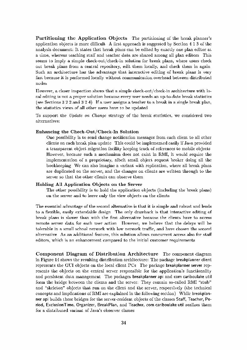
Component Diagram of Distribution Architecture The component diagramin Figure 14 shows the resulting distribution architecture: The package breakplanner.clientrepresents the GUI objects on the local client PCs. The package breakplanner.server rep-resents the objects on the central server responsible for the application's functionalityand persistent data management. The packages breakplanner.api and com.cariboulake.utilform the bridge between the clients and the server: They contain so-called RMI \stub"and \skeleton" objects that run on the client and the server, respectively (the technicalconcepts and implications of RMI are explained in the following section). While breakplan-ner.api builds these bridges for the server-resident objects of the classes Sta�, Teacher, Pe-riod, ExclusionTime, Organizer, BreakPlan, and Teacher, com.cariboulake.util realizes themfor a distributed variant of Java's observer classes.
34

Client PC
breakplanner. client
COM. cariboulake.util
breakplanner. api
Server Workstation
breakplanner. server
COM. cariboulake.util
breakplanner. api
Figure 14: Component Diagram Illustrating the Distribution Architecture
Diagram 14 can also serve as a deployment diagram showing the physical distribution ofthe code needed to run the application. However, deployment diagrams are not very usefulin the context of the Java framework: The deployment of (byte-)code is not a critical taskbecause bytecode can be downloaded automatically at runtime and does not have to beinstalled manually.
5.2.2 Realization with RMI
Client Interfaces and Server Implementation Classes The changes betweenthe business-oriented and the distribution-oriented architecture class diagram (see Figures10 and 5.2.2 on page 37) are simple and almost schematic, as proposed in SUN's tutorial forJava RMI [SUN97c]: Each class whose objects must be accessed from the client is split upinto an interface and an implementation class. The interfaces contain the funcionality usedby the client; they are derived from the standard interface Remote and are given the namesof the original classes. The implementation classes are used on the server; they are derivedfrom class UnicastRemoteObject, and their names are su�xed with Impl. An example is
35

the business-oriented design class Break which was split up into the distribution-orienteddesign class BreakImpl and the corresponding interface Break.
Remote Observer Mechanism Instead of the standard Java class Observable, aremote version has to be used, because observer and observable objects are on di�erentsides of the client/server-gap. We could use the implementation provided in a freelyavailable package from Caribou Lake Software [Car97]. Unfortunately, the name of theobservable implementation class of this package violates the usual naming conventions:Instead of COM.cariboulake.util.Observable it should better be COM.cariboulake.util.RemoteObservableImpl.
Note that the GUI class StatisticsView has to be a remote class, too, because its objectsobserve the Organizer object lying on the application server. Therefore, these client objectsmust themselves be remote servers for the Organizer object's callbacks to their update-method (the control ow with RMI for this case is explained in detail below).
Restricting the Client's Functionality On the one hand, a client of a class shouldbe o�ered su�cient functionality to use the class e�ectively and comfortably for its in-tended purpose. On the other hand, clients should not be allowed to access any additionalfunctionality. This very important design principle makes it easy to change the implemen-tation of methods hidden from the client|it is also known as the principle of \shallowinterfaces" or \loose coupling".
The standard way to achieve this principle in the context of Java is to annotate featuresof a class with access modi�ers like private to hide the features from other classes. In thecontext of RMI, another approach is used: Clients are provided with restricted interfaces,containing subsets of the full class signature. This way a server implementation class canbe derived from several interfaces o�ering di�erent subsets of the functionality.
Having a look at our example we can distinguish two di�erent users of the implementationclasses:
� Clients have access to a rather limited interface. Apart from con icting with the prin-ciple of shallow interfaces, granting all clients access to all server features would opena potential security hole. Clients are, for example, not allowed to connect a Teacher toa Break via the method Teacher::addDuty() because this method does not ensure thebidirectionality of the supervises-association, as the method Break::assignTeacher()does.
� The server must have access to the full functionality of the implementation classes.
The restriction of the client's functionality can be seen in the class diagram of Figure5.2.2 on page 37. The client interfaces contain only parts of the functionality of their cor-responding server implementation classes, and the PeriodImpl class has no client interfaceat all and is, therefore, hidden from the client entirely.
Introduction of BreakPlanner Class A new singleton class BreakPlanner is intro-duced that represents the entry point for clients on the server (see upper right corner ofFigure 5.2.2 on page 37). At runtime, the BreakPlanner object is registered via the rmireg-istry mechanism [SUN97c]. This allows the clients to access the entire application object
36

8QLFDVW5HP
RWH2
EMHFW
5HP
RWH
��,QWHUIDFH!
!
EUHD
NSODQQHU�FOLHQW
6HULDOL]DWLRQ
��,QWHUIDFH!
!
([FOXVLRQ7LPH
��,QWHUIDFH!
!
%UHDN
DVVLJQ7HD
FKHU��
UHPRYH7
HDFKHU��
LV2FFXSLHG�
�KDV&
RQIOLFW��
��,QWHUIDFH!
!
7HD
FKHU
DGG(
[FOXVLRQ7LPH�
�UHPRYH(
[FOXVLRQ7LPH�
�FRXQW([FOXVLRQ7LPHV��
JHW([FOXVLRQ7LPHV��
FRXQW'XWLHV�
�QHHG
HG'XWLHV�
�JH
W-RE
��
VHW-RE
��
JHW1DP
H��
VHW1DP
H��
��,QWHUIDFH!
!
%UHDN3ODQ
DGG%
UHDN��
UHPRYH%
UHDN��
FRXQW%UHDNV�
�JH
W%UHDNV�
�UHPRYH$
OO%UHDNV�
�JH
W3ODFH��
VHW3ODFH��
��,QWHUIDFH!
!
6WDII
DGG7
HDFKHU��
UHPRYH7
HDFKHU��
FRXQW7HD
FKHUV�
�JH
W7HD
FKHUV�
�FRXQW-RE
V��
JHW6FKRR
O��
VHW6FKRR
O��
��,QWHUIDFH!
!
����
([FOXVLRQ7LPH,PSO
���
����
�
���
%UHDN,P
SO
P'XW\�7HD
FKHU,P
SO
DVVLJQ7HD
FKHU��
UHPRYH7
HDFKHU��
LV2FFXSLHG�
�KDV&
RQIOLFW��
�
���
7HD
FKHU,P
SO
P1DP
H�6WULQJ
P-RE�IORDW
P([FOXVLRQV�9HFWRU
P'XWLHV�9HFWRU
DGG(
[FOXVLRQ7LPH�
�UHPRYH(
[FOXVLRQ7LPH�
�FRXQW([FOXVLRQ7LPHV��
JHW([FOXVLRQ7LPHV��
DGG'
XW\�
�UHPRYH'
XW\�
�FRXQW'XWLHV�
�JH
W'XWLHV�
�QHHG
HG'XWLHV�
�GXWLHV:
LWK&RQIOLFW��
H[FOXVLRQ7
LPHV:LWK&RQIOLFW��
JHW-RE
��
VHW-RE
��
JHW1DP
H��
VHW1DP
H��
JHW6WDII��
VHW6WDII��
����
VSHFLILHV
���
����
VXSHUYLVHV
�
���
%UHDN3ODQ,PSO
P3ODFH
�6WULQJ
P%UHDNV�9HFWRU
DGG%
UHDN��
UHPRYH%
UHDN��
FRXQW%UHDNV�
�JH
W%UHDNV�
�UHPRYH$
OO%UHDNV�
�JH
W3ODFH��
VHW3ODFH��
�
���
��
6WDII,P
SO
P6FKRR
O�6WULQJ
P7HD
FKHU
�9HFWRU
�P2UJDQL]HU
�2UJDQL]HU,P
SO
DGG7
HDFKHU��
UHPRYH7
HDFKHU��
FRXQW7HD
FKHUV�
�JH
W7HD
FKHUV�
�FRXQW-RE
V��
JHW6FKRR
O��
VHW6FKRR
O��
JHW2
UJDQL]HU��
VHW2
UJDQL]HU��
��6LQJOHWRQ!!
�
���
�
2UJDQL]HU,P
SO
P%UHDN3ODQV
�9HFWRU
�P6WDII�6WDII,P
SO
DGG%
UHDN3ODQ�
�UHPRYH%
UHDN3ODQ�
�FRXQW%UHDN3ODQV��
JHW%UHDN3ODQV��
FRXQW%UHDNV�
�JH
W6WDII��
VHW6WDII��
VHW&KDQJHG
$QG1RWLI\��
��6LQJOHWRQ!!
�
���
RUJDQL]HV
��
�%UHDN3ODQQHU
VWDUW6HUYHU��
VWRS
6HUYHU��
��
3HULRG,PSO
P%HJ
LQ�7LPH
P(QG
�7LPH
P'D\
�'D\
RYHUODSV��
JHW'D\��
VHW'D\��
JHW+RXU��
VHW+RXU��
JHW0
LQXWH�
�VHW0
LQXWH�
�JH
W'XUDWLRQ�
�VHW'XUDWLRQ�
�
&20�FDULERXODNH�XWLO�5HP
RWH2
EVHUYDEOH
DGG2
EVHUYHU��
GHOHWH2EVHUYHU��
��,QWHUIDFH!
!
��LPSOHP
HQWV!!
��LPSOHP
HQWV!!
��LPSOHP
HQWV!!��LPSOHP
HQWV!!
��LPSOHP
HQWV!!
��LPSOHP
HQWV!!
��LPSOHP
HQWV!!
��LPSOHP
HQWV!!
6WDWLVWLFV9
LHZ
UHGUDZ
��
��,QWHUIDFH!
!��LPSOHP
HQWV!!
��LPSOHP
HQWV!!
��LPSOHP
HQWV!!
��LPSOHP
HQWV!!
��
%UHDN3ODQQHU9LHZ
�
2UJDQL]HU
DGG%
UHDN3ODQ�
�UHPRYH%
UHDN3ODQ�
�FRXQW%UHDN3ODQV��
JHW%UHDN3ODQV��
FRXQW%UHDNV�
�JH
W6WDII��
��,QWHUIDFH!
!
��LPSOHP
HQWV!!
���
6WDWLVWLFV9
LHZ,P
SO
XSGD
WH��
UHGUDZ
��
��
��LPSOHP
HQWV!!
����
���
&20�FDULERXODNH�XWLO�5HP
RWH2
EVHUYHU
XSGD
WH��
��,QWHUIDFH!
!
���
&20�FDULERXODNH�XWLO�2
EVHUYDEOH
DGG2
EVHUYHU��
GHOHWH2EVHUYHU��
VHW&KDQJHG
��
QRWLI\2
EVHUYHUV��
��LPSOHP
HQWV!!
���
���
37

graph via a reference from the BreakPlanner object to the Organizer object. Furthermore,the BreakPlanner object initiates the loading/storing of persistent data whenever it iscreated/destroyed.
Control Flow with RMI To illustrate the ow of control in an RMI-based design,we have included a sequence diagram again (see Figure 15). It is a re�ned version of thesequence diagram of Figure 12 where the following changes have been made:
� The objects are partitioned into a server cluster (to the right) and client clusters (tothe left).
� The classes of the application objects have been su�xed with \Impl", as requiredby RMI.
� For each object acting as a server for remote client objects, we have introduced alocal stub object. These local stub objects are all instances of (a subclass of) theRMI class RemoteStub and implement a corresponding Java interface: break1 andbreak2 (of class BreakImpl_Stub) implement the interface Break, and statisticsView1and statisticsView2 (of class StatisticsViewImpl_Stub) implement the interface Statis-ticsView. Because the Impl_Stub classes are transparent for the user of RMI, we haveused the corresponding interface types Break and StatisticsView in the diagram.
The following two observations are remarkable: First, the RemoteObserver mechanismrequires bidirectional communication between client and server. This can be seen in thesequence diagram, where the client object breakPlannerView1 sends the message assign-Teacher to the server object BreakImpl, and later receives an update request from the serverobject OrganizerImpl. It is interesting that this requirement restricts the target platformquite seriously: It disallows access to the server from outside a �rewall because SUN'scurrent RMI implementation uses HTTP tunneling in this case, and HTTP usually doesnot allow bidirectional communication [SUN97c].
Second, it is notable that two clients can share the same server object without problems.An example is the object breakImpl that has the two stub objects break1 and break2.
We have now cast the complete business-oriented design into the framework of RMI.The interesting and essential point is that this transformation from a universal, abstractdesign to a concrete technical framework could be done almost schematically once thebasic distribution architecture has been chosen.
6 Class Design and Implementation
While UML allows the designer to specify various characteristics of a system, the im-plementation is often limited by the features of the programming framework used. Thissection is concerned about how to get from an UML design speci�cation to an implemen-tation in the context of Java.
6.1 Selection of Data Types
Until now, we have not speci�ed the types of the attributes and the parameters of opera-tions exactly, as this requires knowledge of the implementation language. In our example
38

SODQ(GLWRU�
�3ODQ
(GLWRU
EUHDN3ODQQHU9LHZ�
�%UHDN3ODQQHU9LHZ
EUHDN3ODQQHU9LHZ�
�%UHDN3ODQQHU9LHZ
VWDWLVWLFV9LHZ,P
SO�
�6WDWLVWLFV9LHZ,P
SO
VWDWLVWLFV9LHZ,P
SO�
�6WDWLVWLFV9LHZ,P
SO
EUHDN��
%UHDN
EUHDN,P
SO�
%UHDN,P
SO
EUHDN��
%UHDN
RUJDQL]HU�
2UJDQL]HU,PSO
VWDWLVWLFV9LHZ��
6WDWLVWLFV9LHZ
VWDWLVWLFV9LHZ��
6WDWLVWLFV9LHZ
SODQ(GLWRU�
�3ODQ
(GLWRU ��DVVLJQEUHDNWR
WHDFKHU
��DVVLJQ7HDFKHU��
��DVVLJQ7HDFKHU��
��VHW&KDQJHG$QG1RWLI\
��
6HUYHU�
6LGH
&OLHQW�
6LGH
��VHW&KDQJHG��
��QRWLI\2EVHUYHUV
��
��XSGDWH
��
��XSGDWH
��
��LV2FFXSLHG��
���LV2FFXSLHG��
���KDV&RQIOLFW��
���KDV&RQIOLFW��
���XSGDWH
��
���XSGDWH
��
���LV2FFXSLHG��
���LV2FFXSLHG��
���KDV&RQIOLFW��
���KDV&RQIOLFW��
���UHGUDZ
��
���UHGUDZ
��
���UHFRJQL]HFKDQJHV
PRUH
PHVVDJHVUHWULHYLQJDOO
LQIRUP
DWLRQWR
VKRZ
DFWXDO
EUHDNVWDWLVWLFV
���UHFRJQL]HFKDQJHV
PRUH
PHVVDJHVUHWULHYLQJDOO
LQIRUP
DWLRQWR
VKRZ
DFWXDO
EUHDNVWDWLVWLFV
Figure 15: Sequence Diagram Showing the Communication via RMI
39

the selection was more or less trivial because Java's datatypes were su�cient for our needs.The datatypes chosen can be seen in the class diagram of Figure 5.2.2 on page 37.
6.2 Implementation of Associations
There exist many possibilities for the implementation of associations. Some of them are:
� Reference attributes or|in the case of 1-to-n- or m-to-n-associations|containerswith references can be embedded into the associated classes. If the association mustbe bidirectional, both concerned classes have to be adapted, and the consistency ofthe two directions has to be ensured. Most of our associations follow this implemen-tation scheme. An example is the 1-to-n-association supervises between TeacherImpland BreakImpl. It is implemented by the attribute BreakImpl::duty : TeacherImpl andby the attribute TeacherImpl::duties : Vector.
� Associations can be implemented by a dedicated association class containing refer-ences to the associated objects. We did not use this implementation scheme becauseits only advantage|the possibility to store the association instances between all ob-jects in a container and enumerate them quickly|was of no use in our application.
� Associations to a singleton class can be implemented by an \implicit class reference"in Java. An example for this is the association between OrganizerImpl and Sta�Impl:Sta�Impl could be given a static variable theSta�Impl that is instantiated once dur-ing the initialization of class Sta�Impl. This would make it possible to access thisvariable's object with the Java idiom Sta�Impl.theSta� in the code of other classes.However, we decided not to use this idiom because it does not restrict the access tothe singleton instance for other classes importing the package.
6.3 Separation of Client and Server Functionality
As explained in the previous section, we have restricted the client's view onto the server'sfunctionality by including only a subset of the server class operations into the clientinterfaces. This approach has the problem that the server needs to cast objects frominterface types to server types in order to use the additional server functionality, as canbe seen from the following example: Imagine that the client wants to assign a teacherto a break by calling Break::assignTeacher(t) where the parameter t is of type Teacher. IfBreak::assignTeacher(t) now wants to call t.addDuty(), it must �rst cast t to type Teacher-Impl.
To clearly separate these potentially unsafe casts in our code, we have provided di�erent,but semantically equal methods for each operation that is accessible for the client as wellas for the server:
Server Methods are declared only in the server implementation classes and implementthe functionality of the method. Their signatures contain only implementation classtypes (the ones su�xed by \Impl"). To distinguish these methods from the clientmethods, their names are pre�xed with the letter `i' (for implementation).
Client Methods are declared in the client interface and implemented in the server im-plementation class. They provide no own functionality, but serve only as a wrapper
40

for the server methods. Their signatures contain only interface types. Client meth-ods have a very simple, schematic implementation consisting of the following actions:
� Find the corresponding implementation object for the remote reference parame-ter (this step is described in more detail in section 7.9, paragraph \RMI CoerceWorkaround").
� Cast down the types of all actual parameters from remote client interface typesto server implementation types.
� Call the corresponding server method.
� Cast up the type of the result parameter|provided one exists|to a remoteclient interface type.
Apart from the gained clarity of the implementation, this scheme has the advantagethat the server functionality can be easily tested stand-alone by considering only servermethods. If the server is stable enough, one can then deal with the additional issuesintroduced by distribution. Another advantage is the improved performance: Once thetranslation to server objects has been done by the client method, all its method callsto the parameter objects on the server run locally and do not involve stubs or remotereferences.
6.4 Packaging of Java Source Code
In Java, packages contain a group of classes logically related to each other. Operations,attributes, and whole classes can be hidden from other classes or other packages. Packagescan import other packages that contain needed functionality. These concepts can bemodeled with the UML package concept, as can be seen in Figure 16, which shows thefour packages of the break planner application as well as the import relations betweenthem.
Note that the client does not import the package breakplanner.server with the implemen-tation classes for the system's remote objects.
6.5 Implementation of Method Bodies
The implementation of the method bodies is the last step towards a working program.In our case, most of the methods have trivial implementations, apart from some slightlymore complex ones like TeacherImpl::dutiesWithCon ict. The source code of the systemcan be found in [RS97].
7 Comments
The comments in the following sections do not cover all aspects of UML or Java. Most ofthem are motivated by concrete problems with these techniques during the developmentof the break planner application.
41

breakplanner.server
+ TeacherImpl+ BreakPlanImpl+ BreakImpl+ PeriodImpl+ StaffImpl+ OrganizerImpl+ ExclusionTimeImpl+ BreakPlanner
breakplanner.api
+ Staff+ Teacher+ ExclusionTime+ Break+ BreakPlan+ Organizer
breakplanner.client
+ BreakPlannerView+ StatisticsView
COM.cariboulake.util
+ RemoteObserver+ RemoteObservableImpl+ RemoteObservable
<<imports>>
<<imports>><<imports>>
<<imports>>
Figure 16: The Package Structure of the Implementation
7.1 Use Case Diagrams
Seen as an isolated description technique, use case diagrams are not a very powerfulformalism: They contain not very much information about the functionality of a system,but are used mainly as a structuring aid for other kinds of diagrams. On the otherhand, they can be easily understood by customers, and they are very useful for earlyrequirements analysis because they enforce the identi�cation of the di�erent users anduses of a system.
In the so-called \semantics de�nition" of [BRJ97], it is \the responsibility" of a use caseto \specify a set of use case instances, where a use case instance represents a sequenceof actions a system performs that yields an observable result of value to a particularactor" (`actor' means `user' in our context). The action sequences of a use case may bedescribed and speci�ed by means of other description techniques like sequence diagrams,collaboration diagrams, and activity diagrams.
In the meta-model provided by the UML authors the concept of a use case is derivedfrom the \Type" concept. A somewhat strange e�ect of this derivation is that use casesinherit some properties that we can not make sense of. As expressed in section 7 of thesemantics document [BRJ97], they have attributes and operations, but it is not explainedwhat these attributes and operations should be|in our eyes their presence con icts withthe semantical de�nition of a use case as a set of action sequences.
Another unclear point concerns the semantics of the �uses� and �extends�-relations.Apart from informal descriptions, where both relations are equally described as a sort of\inclusion" or \extension", the UML 1.0 semantic de�nition documents provide no usefulinformation on this issue.
A possible interpretation of A �uses� B is given by the following conditions, following
42

Coleman [Col97]:
� A incorporates B as a sub- ow of events. It must be speci�ed where B is inserted.
� The details of use case B are hidden from A.
� B is a fully edged use case and may involve some or all of A's connections.
With respect to the corresponding sequences, this can be interpreted as: One or moresequences of A's sequence set contain sequences of B's sequence set as contiguous sub-sequences at certain locations in time. Note that although this situation very muchresembles a procedure call in programming languages, one cannot assume the presence ofa \runtime connection" or a procedure call between two use cases because use cases areonly conceptual modeling constructs usually not directly implemented in a system.
In contrast to this, the situation B �extends� A can be de�ned by other conditions, againfollowing [Col97]:
� Two use cases are de�ned: A and A extended by B.
� B is a variation of A. It contains additional events (e.g. for a failure or to deal withan extra complexity) for certain conditions.
� It has to be speci�ed where B is inserted in A.
� B is not a fully edged use case.
With respect to the corresponding sequences, this can be interpreted as: B contains allaction sequences of A and furthermore adds own sequences that contain sequences of Aas (possibly non-contiguous) subsequences.
Other questions left open by [BRJ97] are:
� Is it possible to have a use case without a connection to a user?Such a use case would in some way contradict with the purpose of a use case asa modeling concept for the usage of a system by users, but could be handy formodeling internal system tasks that can be handled automatically and do not needhuman interaction.
� If a use case A is extended by a use case B, does A have to be connected with allusers of B? And does B have to be connected with all users of A?We think the answer to both of these questions is negative, considering the example ofa hypothetical use case Edit Data extended by Edit Con�dential Data, which containsadditional functionality for authorization. In this example, there may well be (classesof) users associated exclusively with only one of these use cases.
� If a use case A is extended by a use case B, must B have �uses�-connections to thesame use cases as A?According to the sequence interpretation of use cases given above, the answer mustbe yes. However, it is the question whether such obligatory and, therefore, redundantconnections should be represented in a use case diagram. Our recommendation is todraw them only if the extended use case introduces own functionality that �uses� theconcerning use case also, and to leave them out otherwise.
In our opinion, use cases should have a stronger connection to class diagrams. We havetherefore included in the dictionary entry of each use case a Data-line containing the
43

classes concerned by the use case (see Section 4.1.2). By comparing the actions of the usecase with the attributes and operations of the classes, one can check whether the classescontain all functionality needed (and not more than needed) and get hints about whatdata is shared among which users. A better way to visualize the correlation betweenclasses and use cases could be provided by a tool that highlights the classes belonging toa certain use case in the class diagram.
In total, we think that UML use cases are a valuable tool for requirements analysis. Aclear de�nition of their syntax and semantics seems to be possible, but is missing in[BRJ97].
7.2 Class Diagrams
Semantics of Associations Although class diagrams are a well-known formalismin many object-oriented development methods, their semantics is not totally clear withrespect to associations. We have explained some possibilities for the translation into codein Section 6.2.
Boundary Concept Class diagrams as used in UML lack the concept of a systemscope, making it hard to distinguish entities that must be implemented from entities inthe environment of the system. This is in general true for all description techniques ofUML except for use case diagrams where this boundary is represented by the rectangleenclosing the use case ellipses. The addition of a system boundary concept, as e.g. inFusion [CAB+94], would �ll this gap.
Instance Diagrams In general, class diagrams do not constrain the possible objectgraphs that may occur during the runtime of a program. However, for the special case ofthe class diagram in Figure 8 with its two singleton classes and its tree-like aggregationstructures, all object graphs allowed by the class diagram are admissible, so that additionaldescription techniques are not necessary.
We have not included an instance diagram because it would have been very large evenfor a small example with only a few breaks and teachers. In order to comprehend thetangled object graphs that arise in the context of more complex class diagrams, morepowerful description and speci�cation formalisms than instance diagrams are needed, like,for example, component diagrams as introduced in [Ber97].
Re�nement As described in Section 5.1, the essential step in system design is toconstruct a detailed, re�ned class diagram from the analysis class diagram. AlthoughUML contains notations to represent re�nement steps, we could not use them in ourmodel:
The proposed notation for \re�nement within a given model" would have led to a huge,incomprehensible model containing all the classes of the di�erent development phasestogether with their re�nement relations (see [BRJ97], Notation Guide, Section 4.26, andleft side of Figure 17). In our opinion, this variant should be restricted to the special casethat one wants to demonstrate the re�nement of a single entity explicitly.
The notation for \re�nement between models" is based on \an invisible hyperlink sup-ported by a dynamic tool" and is, therefore, not a suitable notation for a paper-based
44

presentation. We think that a simple and general notation for the representation of re�ne-ment relations between models should be introduced that is usable also for a paper-basedpresentation. We propose the use of a special symbol for this purpose, reminiscent of aback-reference as well as of a generalization arrowhead (see right side of Figure 17).
StringSet VectorStringSet<<type>>
StringSetVectorStringSet
Figure 17: Representation of Re�nement Within and Between Models
The semantics of re�nement relations is left entirely open in UML|there are no rulesclarifying which re�nement steps exist and when they can be applied. A more formaltreatment would allow the implementation of tools that support or maybe even automatethe execution and validation of re�nement steps. Some examples for possible re�nementsteps are contained in sections 5.1.1 and 5.2.2 for class diagrams, and in sections 5.1.3and 5.2.2 for sequence diagrams.
Responsibilities UML lacks a notational construct for grouping attributes and oper-ations of a single class together into so-called \responsibilities", a concept introduced byWirfs-Brock [WBWW90].
We propose to use a simple, tree-like notation, where responsibilities are represented inbold font above the indented names of their contained elements (see Figure 18). A toolcould then be used for switching between folded and unfolded views.
mName : StringmJob : float
mDuties : VectormStaff : Staff
addExclusionTime()removeExclusionTime()countExclusionTimes()getExclusionTimes()addDuty()removeDuty()countDuties()getDuties()neededDuties()dutiesWithConflict()exclusionTimesWithConflict()getJob()setJob()getName()setName()getStaff()
[manages n Duty]
setStaff()
mExclusionTimes : Vector
Teacher
Teacher
mJob : float
dutiesWithConflict()exclusionTimesWithConflict()
+name
-Associations+exclusionTimes
+staff
-job
-Data
-Functionality
-supervisesvoid addDuty(Duty)void removeDuty(Duty)Enumeration getDuties()int countDuties()
[readwrite float]
float getJob()setJob(float)
Figure 18: Grouping of Class Features with Responsibilities
Even in the context of relatively small class diagrams like the ones of the break planner, re-sponsibilites would allow to comprehend the structure of classes with many features muchfaster. The use of equally named responsibilities in di�erent classes could furthermorehelp in understanding mechanisms implemented by collaborating classes. An example
45

would be the use of MVC responsibilities, grouping together the collaborating operationsin various model, view and controller classes.
Responsibilities can �rst be introduced during requirements analysis to specify the dataand functionality of a class informally, leaving open the �nal names and signatures ofits operations and attributes. During design and implementation, responsibilities canthen be re�ned stepwise by adding attributes, operations, and also other responsibilities.Specialized documentation tools like javadoc [SUN97a] could also use responsibilities topresent class features in a structured way.
Another possibility is the use of standardized responsibility schemes that could be un-folded automatically with the help of a tool. This would for example be useful for thehandling of associations or data attributes, where the same patterns of attributes and ac-cess operations appear over and over again in a detailed class diagram. An example for aresponsibility schema is a scalar attribute, like job in Figure 18: It is usually implementedby the attribute itself and two access methods getJob and setJob for reading/writing theattribute's value. Another example are managed 1-to-n associations like supervises thatare usually implemented by a special pattern of operations (cf. section 5.1.4).
Interfaces According to UML, an interface should be represented as a little, namedcircle next to the class implementing the interface. The advantage of this notation is that itneeds less diagram space and fewer lines in comparison to a class-like representation. Thedisadvantage is that one can not see the operations of an interface in the class diagram.There is also no notation for representing subtype relations between interfaces.
The notation should therefore only be used for standard interfaces with known functional-ity that are not subtyped. A good example in the context of Java is the standard interfaceSerializable. However, we have not used this notation in the class diagrams of Figures 10and 5.2.2 because our tool did not provide it (cf. Section 7.10).
If the operations of an interface are important or an interface is subtyped|for example inthe case of the observer interface in Figure 10 or all remote interfaces in Figure 5.2.2|,we recommend to use a class-like notation where interfaces are marked with the specialstereotype �Interface�.
However, one should not assume that all interfaces are Java interfaces: Sometimes oneonly wants to denote a certain subset of the functionality of a class as an interface. In thiscase no interface type exists, and the class-like notation would thus be misleading. Forthis purpose, we propose to use a special kind of a responsibility containing the speci�erInterface in its name.
7.3 Sequence Diagrams
Sequence diagrams show exemplary interactions between objects. They emphasize thetime dimension and contain the association links between the objects only implicitly.
It is out of question that sequence diagrams are a useful description technique: In our ex-perience, they are|together with class diagrams|the predominant description techniquein design meetings. Furthermore, sequence diagrams can be given a precise semantic, asis for example shown in [BHKS97].
UML enhances sequence diagrams with a notation for modeling the message ow between
46

\entire sets of objects" instead only between single objects. It is however not clear whatthe semantics of this construct is|is a message related to all or only some of the objectsin the set? If the latter is true, how is the subset speci�ed?
Sequence diagrams could be used as test cases for an existing implementation of a sys-tem. For this purpose, additional information like preconditions, input data, and testinstructions should be provided for sequence diagrams, and there should be methodicalguidelines on the usage of sequence diagrams for testing.
In addition to \exemplary" sequence diagrams, the UML variant contains features likeconditional subsequences that make sequence diagrams useful also for the speci�cationof behavior. However, there exists no notation to discern sequence diagrams meant ascomprehensive speci�cations of all possible interactions from sequence diagrams showingjust exemplary interactions. It is also not clear for which object con�gurations a se-quence diagram speci�cation is valid|does the sequence diagram imply that only certaincon�gurations appear during the runtime of a system or does it apply only in certainsituations?
7.4 Collaboration Diagrams
Collaboration diagrams resemble sequence diagrams in most respects. However they em-phasize the relationships between objects and show the ow of time only implicitly usingsequence numbers.
An automatic translation between sequence diagrams and collaboration diagrams is, there-fore, possible with one exception: Connections not used for communication can only berepresented in collaboration diagrams. Apart from this rather unimportant issue, it seemsjust a matter of personal style which of both techniques one wants to use.
The authors of [BRJ97] also propose the usage of \before-after conditions" for declarativespeci�cations of the behavior of a type's instances. However, it is left totally unclearhow this formalism is related to the other description techniques for the speci�cation ofa system's dynamics, what formalisms are admissible in before-after conditions, and howthe \context" of a type should be de�ned. We have, therefore, not included a collaborationdiagram for the types of the break planner application.
Another collaboration notation is used for design patterns which would otherwise not bevisible in a class diagram. This notation has proved valuable to describe the presence ofthe observer pattern in our application (see Section 5.1.3). Yet, it is doubtful whethermore complex design patterns could be integrated into a class diagram equally simple|the di�erent components of the microkernel pattern in [BMR+96] represent, for example,rather subsystems than classes, so that mapping them to simple classes makes no sense.
7.5 State Diagrams
State transition diagrams are a universal and well-known formalism for specifying thestate space and the state transition relation of entities. However, most questions abouttheir methodical use and about their semantics in the context of object-oriented modelingare left open in the UML speci�cation. Consistency criteria and methodical guidelinesfor the simultaneous use and the transition between activity diagrams, state diagrams,sequence diagrams, and collaboration diagrams are urgently needed.
47

A similar problem concerns the consistency between di�erent, but related documents ofa single dynamic description technique. Classes related by inheritance should inherit notonly attributes and operation signatures, but also dynamic behavior as speci�ed by theclass state diagrams of their base classes [Rum96], and re�ned versions of classes shouldhave a suitably re�ned behavior. Also needed is the possibility to assign a state diagramto a compound component and to break it down into subordinate state diagrams.
7.6 Activity Diagrams
As mentioned in Section 2.1, activity diagrams can be used on di�erent levels of abstrac-tion. In our project, we have used them for business process modeling (see Sections 4.1.4and 4.1.6) as well as for specifying the behavior of single operations (see Section 5.1.5).
Although the use of activity diagrams for business process modeling during the analysisphase seems like a simple and natural concept, their implementation and translation tosource code is not trivial. In principle, the following possibilities exist:
Explicit Control: Activity diagrams serve as an explicit, operational speci�cation for aspecialized work ow engine controling the functionality of components of a system.Using a work ow engine seems to become a common architecture for the integrationof legacy components (which may be also whole programs) into a larger system.
Implicit Control: Activity diagrams serve as a speci�cation for the interaction of com-ponents. This approach is common with user interfaces, where the control ow willlikely not be implemented by a centralized work ow component, but will be inte-grated in the callbacks and operations of the GUI classes. When used to specify theinteractions of GUI elements, activity diagrams resemble the so-called \interactiondiagrams" of Denert [Den91].
To facilitate the translation to source code or to even allow an automated implementationvia tools, the semantics of activity diagrams must be clearly de�ned. This would also helpthe user to understand the connection between action states and actual programs or GUIprototypes.
Another critical point is the lack of methodical guidance for the transition from exemplarysequence diagrams to prescriptive activity diagrams: In general, it is not trivial to identifythe common characteristics of a set of possible sequences and to build suitable activitydiagrams that allow all these sequences. This is particularly di�cult because a singleaction sequence can in principle be the result of the interleaved execution of more thanone use case.
UML states that an activity diagram is \a special form of a state diagram". As such, itshould use the syntactical constructs introduced in the section on state diagrams. How-ever, that seems not to be the case with so-called \complex transitions", especially whenthe \swimlane" notation is used. First, there is a minor inconsistency in Figure 50 of[BRJ97]: Complex transitions are represented there by short heavy horizontal bars in-stead of short heavy vertical bars, as speci�ed in section 8.6.2. Second, the diagram inFigure 53 of [BRJ97] (see Figure 19) contains action states like Pay and Take order inswimlane Sales that are meant to run concurrently, but it does not have any complextransition. The correct representation should resemble the activity diagram of Figure 6in this respect.
48

Customer
Request service
Sales Stockroom
Pay
Take order
Fill order
Deliver order
Take order
Figure 19: Activity Diagram with Concurrent States of [BRJ97]
Although activity diagrams are intended to specify the dynamic behavior of a system,they can not deal with changing object graphs properly: This can be seen from diagram13: It contains two swimlanes, namely Break and Teacher. While the action hasCon ictbelongs to a special, single object, the action overlaps is executed for all instances of Breakthat are connected to its supervising Teacher object. However, there is no notation todiscern actions concerning a single object from actions concerning a whole set of objectsin the same swimlane.
During design, activity diagrams can be used to specify the control ow of methods.When used for this purpose, they are very similar to well-known techniques like Nassi-Shneidermann charts or owcharts. However, most operations in object-oriented programsare very simple and creating an activity diagram for them would not introduce additionalclarity.
7.7 Implementation Diagrams
There exist two forms of implementation diagrams: Component diagrams model the dis-tribution of object instances at runtime, while deployment diagrams model the locationof the object code. These two views are isomorphic only in the special case that eachobject instance has its own program code.
However, UML seems to neglect the di�erence between component and deployment dia-grams and allows combined diagrams containing both aspects. This is shown in Figure20, which contains Figures 56 and 57 of [BRJ97]: The component diagram on the rightcontains the program component Scheduler that accesses the component instance meet-ingsDB.
The notation provided seems also overly simple. It does, for example, not contain conceptsfor inheritance and recursive containment of component instances, and it allows onlythe representation of static con�gurations consisting of a �xed number of hard-wiredcomponent instances. To overcome these limitations, more powerful formalisms like theone proposed in [Ber97] are needed.
Finally, UML says nothing about the relation of implementation diagrams to the other
49

Scheduler
Planner
Component Diagram:reservations
update
GUI
Deployment Diagram:
AdminServer:HostMachine <<database>> meetingsDB
reservations
Scheduler
Joe's Machine:PC
Planner
Figure 20: Component and Deployment Diagrams in [BRJ97]
description techniques. This would be necessary especially for instance diagrams, sequencediagrams, and collaboration diagrams because these diagrams also refer to object andcomponent runtime con�gurations.
7.8 User Interface Prototype
The decision to build a GUI prototype of an application may have three (classical) reasons:
1. The look-&-feel of the �nal system can be demonstrated and the adequacy of theuser interface can be evaluated (explorative prototyping).
2. Experience with a concrete implementation technique can be gained in the contextof a small, manageable system (experimental prototyping).
3. The code of the prototype can be reused in the �nal system (evolutionary prototyp-ing).
We think that we could achieve the �rst two goals reasonably well. The demonstratedlook-&-feel seems acceptable, although the lack of a drag-&-drop mechanism in Java 1.0.2complicates the interaction with the program. The experiences of Klaus Berg and BriktiusMarek with Visual Caf�e [Sym97] were quite positive. We can not comment on the thirdpoint because the integration of the GUI prototype with the rest of the system has notstarted yet.
To build a GUI prototype, one should at least have the information from a �rst use caseanalysis. Especially the information about usage frequency and the experience level of theusers (cf. Sections 4.1.2 and 4.1.3) can provide hints for the design of the user interfaceand the help system.
Besides the `look' of a program's screen layout, a user interface prototype also demon-strates the `feel' of the interaction. This includes dynamic aspects, e.g. the navigationbetween the dialog elements, the creation or deletion of windows, and the enabling or dis-abling of input �elds. Although these aspects can be described by sequence diagrams andactivity diagrams, detailed models of user interfaces would be large and di�cult to un-derstand, especially compared to the very intuitive experimentation with the prototype.On the other side, a prototype can also mislead the user because it may, for example,simulate response times that can not be met by the �nal system.
50

Our recommendation is, therefore, to model at least all important dynamic aspects thatcan not be simulated with a user interface prototype by means of other, more formaldescription techniques. We have done so with the update of the break statistics in Section4.1.5.
7.9 Java, Object Serialization and Remote Method Invoca-
tion
During the implementation process we encountered a couple of problems with Sun's JDK[SUN97b]:
Singleton Gripe The singleton characteristics of a class is not supported by Java. We,therefore, implemented our own mechanism to make sure that always exactly oneinstance of the classes Sta� and Organizer exists. We use a newly introduced excep-tion called SingletonException signaling attempts to create more than one instanceof these classes.
Serialization of Static Attributes Object serialization supports the encoding of com-plete object graphs into a stream of bytes and vice versa. However, referencescontained in static attributes are ignored and must thus be handled separately.
RMI Coerce Workaround If a client sends the server a reference to one of the server'sown remote objects, the server can not typecast that reference to the correspondingimplementation object. The reason for that is that the server does not get a localreference, but instead a reference to a stub object that accesses the \real" implemen-tation object via a skeleton. To invoke server-only methods|methods not containedin one of the remote interfaces accessible to the clients|, one has to maintain a ta-ble with this relation on the server. In our implementation [RS97], we use the extraclass InterfImplHandler for that purpose.
Remote Observer Obstacle During the implementation phase we found ourselves un-able to combine Java's observer mechanism with the RMI concept. Neither inher-itance nor wrapper-based techniques make it possible to create a remote observermechanism on top of Java's standard observer classes. The only remaining solutionis a total re-implementation of the needed functionality. Fortunately, we did nothave to do this by ourselves because we could use a free implementation providedby Caribou Lake Software (see [Car97]).
Remote Object Inheritance RMI Objects are made remote by inheriting from theclass RemoteObject. This forces the programmer to make all classes in a hierarchyremote if actually only one class is intended to be remote. Although this was noproblem for our application, \disinheriting" non-remote classes from remote onesduring distribution design could necessitate extensive transformations of the classhierarchy and the corresponding algorithms.
7.10 Tool Support
We used the tool Rational Rose 4.0 for the creation of most of our diagrams, as it wasone of the �rst CASE tools to support the UML notation. Rational Rose 4.0 can bedownloaded from Rational's Homepage [Rat97] in a demo version for the language C++ on
51

the Windows 95 platform. The tool supports a broad selection of the notations proposedin the UML documents, but has also some aws:
Static Structure Diagrams Class diagrams in Rose lack some features like the circlenotation for interfaces and the various presentation options for aggregations.
Use Case Diagrams: Use case diagrams are well supported by the tool. However, Rosedoes not allow to draw the system boundary box around the use cases.
Sequence Diagrams: Rose lacks UML's notation for creation and deletion of objects.
Collaboration Diagrams: The collaboration diagram in Figure 11 has been drawn onlypartly using Rose because the tool cannot show the occurrence of a design patternin a class diagram. In addition, specifying a collaboration for a type, like introducedin section 7.3.3 of [BRJ97], is not possible.
State Diagrams: With the exception of concurrent states, state diagrams are well sup-ported.
Activity Diagrams: Simple activity diagrams can be drawn. Concurrent states, deci-sions and swimlanes are missing.
Implementation Diagrams: Neither component diagrams nor deployment diagrams asspeci�ed by [BRJ97] can be created using the current version of Rose. The supportedimplementation diagrams are quite dubious: On the one hand some basic elementslike interfaces and nodes are missing, on the other hand additional elements liketasks or processors are available.
8 Conclusion
In this paper we have provided an example for the development of a distributed Javaprogram using UML 1.0. We have described the development process we followed and thedesign decisions we have made, as well as the di�culties we have encountered.
All in all our experiences with UML were not totally negative|we could overcome allproblems and were able to model most aspects of the break planner system. However,this does not imply that UML is a mature modeling language that can be used for realprojects without problems. Our main criticisms are:
� UML provides a wealth of description techniques, but de�nes neither their syntaxnor their semantics precisely and unambiguously. This makes modeling sometimesdeceptively easy because one is allowed to draw all kinds of diagrams that have nouseful meaning for the subsequent implementation.
� The missing semantic foundation is also problematic with respect to the relationshipsbetween the various development documents, especially when it comes to describ-ing the dynamic behavior of a system: Because there exist no consistency criteriabetween description techniques it is hard to check whether all of their requirementscan be combined and ful�lled by the implementation. Consistency criteria and me-thodical guidelines could also make the production of development documents easierbecause they restrict the possibilities of the developers and force them to consideronly meaningful diagrams.
52

� The same considerations apply to UML's concept of re�nement|it is not de�nedwhen a development document is a re�ned version of another document and whatdevelopment steps are admissible for re�ning documents.
� UML's description techniques cannot deal su�ciently with complex, changing ob-ject graphs and hierarchical composite objects. The existing notations for so-called\multi-objects" in sequence and collaboration diagrams seem very ad-hoc and leavemany questions open, as well as the whole description technique of component dia-grams.
� UML lacks abstraction techniqes for large class diagrams with many attributes andoperations.
� Some of the techniques of UML aim at the implementation of a CASE tool and can-not be presented on paper. An example are most relationships between developmentdocuments which shall be represented by \invisible hyperlinks" according to UML'sde�nition.
� The UML Notation Guide and the UML Semantics Document [BRJ97] do not con-tain contain su�cient examples and are not very readable, if not to say confusing.This is especially true for the Semantics Document: Large parts of it seem to bemachine-generated English, the index is nearly unusable because it contains toomany references for each entry, and the de�nitions contained are informal and un-clear.
Our valuation of Java is more positive. The main problems we encountered concerned theRMI mechanism which o�ers no support for the restriction of a remote client's functional-ity. However this problem could be overcome relatively easily by a schematic workaround.
Acknowledgements
We thank Ruth Breu, Ingolf Kr�uger, Bernhard Rumpe, and Alexander Vilbig for interest-ing discussions and comments on earlier versions of this report. We are especially indebtedto Ingolf Kr�uger who did a careful proofreading of large parts of the paper.
References
[Ber97] Klaus Bergner. Spezi�kation gro�er Objektge echte mit Komponentendia-grammen. CS Press, 1997.
[BHH+97] Ruth Breu, Ursula Hinkel, Christoph Hofmann, Cornel Klein, BarbaraPaech, Bernhard Rumpe, and Veronika Thurner. Towards a formaliza-tion of the uni�ed modeling language. TUM-I 9726, Technische Universit�atM�unchen, 1997.
[BHKS97] Manfred Broy, Christoph Hofmann, Ingolf Kr�uger, and Monika Schmidt. Agraphical description technique for communication in software architectures.TUM-I 9705, Technische Universit�at M�unchen, 1997.
[BM97] Klaus Berg and Briktius Marek. GUI prototype for the break planner ap-plication, 1997.
53

[BMR+96] F. Buschmann, R. Meunier, H. Rohnert, P. Sommerlad, and M. Stal.Pattern-Oriented Software Architecture | A System of Patterns. Wiley& Sons, 1996.
[Boo94] G. Booch. Object-Oriented Analysis and Design with Applications. Ben-jamin/Cummings, 2 edition, 1994.
[BRJ97] G. Booch, J. Rumbaugh, and I. Jacobson. Uni�ed Modeling Language, Ver-sion 1.0. Rational Software Corporation, URL: http:/www.rational.com,2800 San Tomas Expressway, Santa Clara, CA 95051-0951 (USA), 1997.
[CAB+94] D. Coleman, P. Arnold, S. Bodo�, C. Dollin, H. Gilchrist, F. Hayes, andP. Jeremes. Object-Oriented Development | The Fusion Method. PrenticeHall, 1994.
[Car97] Caribou Lake Software. Remote Observer Classes, http://www.cariboulake.com/utils.html, 1997.
[Che76] P. P. S. Chen. The entity-relationship model | toward a uni�ed view ofdata. ACM Transactions on Database Systems, 1(1), 1976.
[Col97] Coleman. Slides on uml use case modeling, 1997.
[DAC] DACH Group. Universit�at Hamburg, FB Informatik, AB Softwaretechnik;Johannes-Kepler-Universit�at, Linz, Austria, Institut f�ur Wirtschaftsinfor-matik, Doppler-Labor f�ur Software Engineering; GMD Bonn, Schlo� Bir-linghoven, St. Augustin; UBS Information Technology Laboratory, Zurich,Switzerland.
[Den91] E. Denert. Software Engineering. Springer-Verlag, 1991.
[Fla96] D. Flanagan. Java in a Nutshell. O'Reilly & Associates, Inc., 1996.
[GHJV95] E. Gamma, R. Helm, R. Johnson, and J. Vlissides. Design Patterns: Ele-ments of Reusable Object-Oriented Software. Addison-Wesley, 1995.
[IT93] ITU-TS. ITU-TS Recommendation Z.120: Message Sequence Chart (MSC).ITU-TS, Geneva, September 1993.
[Jac92] I. Jacobson. Object-Oriented Software Engineering | A Use Case DrivenApproach. Addison-Wesley, 1992.
[Jav95] JavaSoft, A Sun Microsystems, Inc. Business. http://java.sun.com, 1995.
[Jav97] Java security { frequently asked questions, 1997.
[LRH97] Stefan Loidl, Ekkart Rudolph, and Ursula Hinkel. Msc'96 and beyond { acritical look. In A. Cavalli A. Sarma, editor, SDL Forum 97. Elsevier, 1997.
[Rat97] Rational. Rational Rose 4.0 Demo, http://www.rational.com/demos,1997.
[RBP+91] J. Rumbaugh, M. Blaha, W. Premerlani, F. Eddy, and W. Lorensen. Object-Oriented Modeling and Design. Prentice Hall, 1991.
[RS97] Andreas Rausch and Marc Sihling. Source code for the break plan-ner application backend, http://www.forsoft.de/interna/projekte/a1/fallstudien/bp.tar.gz, 1997.
[RSLML96] S. Roock, K.-H. Sylla, C. Lilienthal, and A. M�uller-Lohmann. DerPausenplaner { Szenario, CRC-Karten, Systemvision, http://set.gmd.de/~sylla/dachpap-aufgabe.html, 1996.
54

[Rum96] Bernhard Rumpe. Formale Methodik des Entwurfs verteilter objektorien-tierter Systeme. Tum doktorarbeit, Technische Universit�at M�unchen, 1996.
[SCB95] Patricia S. Bilow Steven Craig Bilow. Distributed systems design. In OOP-SLA'95, Addendum to the Proceedings. ACM Order Department, 1995.
[SHB96] Bernhard Sch�atz, Heinrich Hussmann, and Manfred Broy. Graphical de-velopment of consistent system speci�cations. In James Woodcock Marie-Claude Gaudel, editor, FME'96: Industrial Bene�t and Advances In FormalMethods, pages 248{267. Springer, 1996. Lecture Notes in Computer Science1051.
[SM88] S. Shlaer and S. J. Mellor. Object-Oriented Systems Analysis. Prentice Hall,1988.
[SUN97a] SUN Microsystems. javadoc { the Java API Documentation Gen-erator, http://java.sun.com/products/jdk/1.1/docs/tooldocs/win32
/javadoc.html, 1997.
[SUN97b] SUN Microsystems. The JDK 1.1.2 Documentation, http://java.sun.com/products/jdk/1.1/docs, 1997.
[SUN97c] SUN Microsystems. RMI { Remote Method Invocation, http://java.sun.com/products/jdk/1.1/docs/guide/rmi, 1997.
[Sym97] Symantec. Symantec's Visual Caf�e, http://www.symantec.com/vcafe,1997.
[WBWW90] R. Wirfs-Brock, B. Wilkerson, and L. Wiener. Designing Object-OrientedSoftware. Prentice Hall, 1990.
55