Embed Size (px)
Citation preview

Double Control Loop Design
‐ 1 ‐ Powersim Inc. www.powersimtech.com
SmartCtrl Tutorial
Double Control Loop Design
Double Control Loop Design
‐ 2 ‐ Powersim Inc. www.powersimtech.com
SmartCtrl1 is a general‐purpose controller design software specifically for power electronics applications. This tutorial is intended to guide you, step by step, to design the controller (or regulator) of a dc/dc converter with double control loops using the SmartCtrl software.
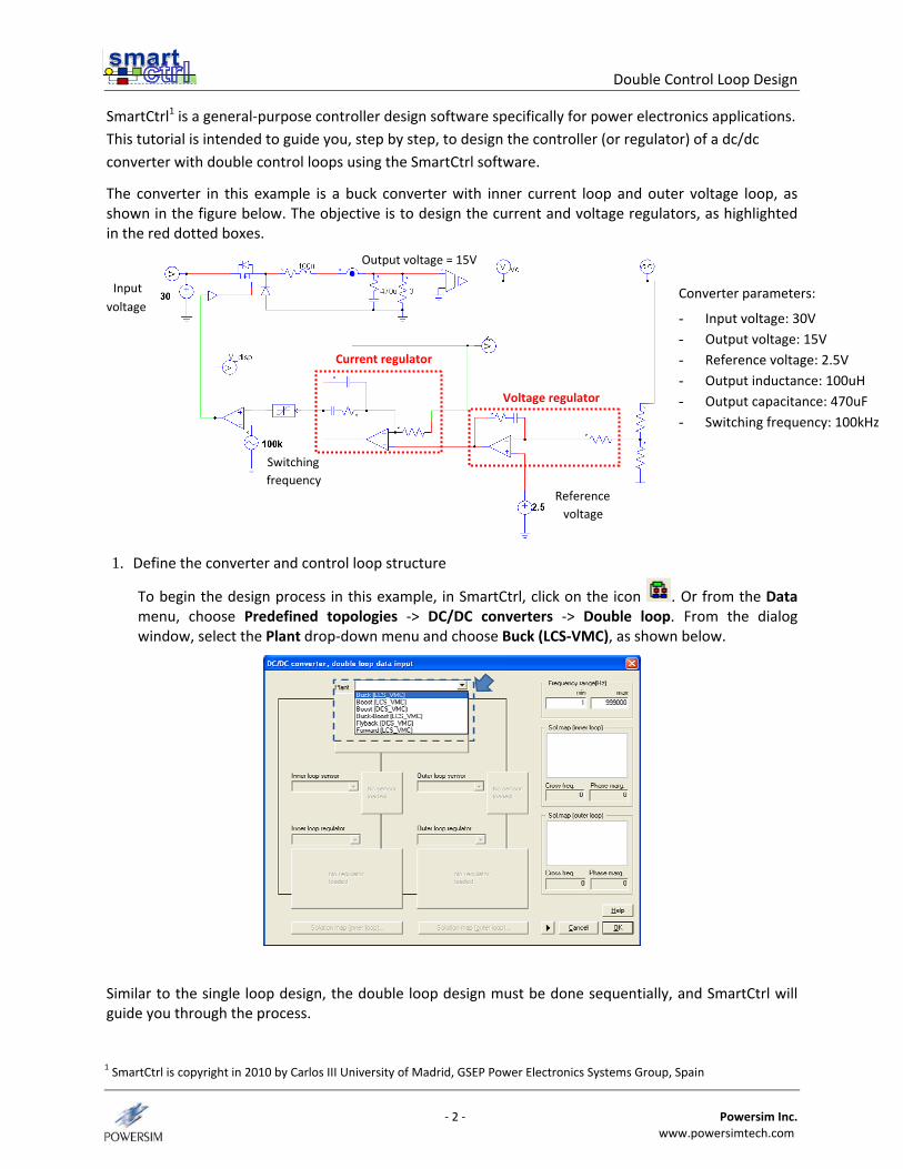
The converter in this example is a buck converter with inner current loop and outer voltage loop, as shown in the figure below. The objective is to design the current and voltage regulators, as highlighted in the red dotted boxes.
Input voltage
Switching frequency
Output voltage = 15V
Reference voltage
1. Define the converter and control loop structure
To begin the design process in this example, in SmartCtrl, click on the icon . Or from the Data menu, choose Predefined topologies ‐> DC/DC converters ‐> Double loop. From the dialog window, select the Plant drop‐down menu and choose Buck (LCS‐VMC), as shown below.
Similar to the single loop design, the double loop design must be done sequentially, and SmartCtrl will guide you through the process.
Converter parameters:
- Input voltage: 30V - Output voltage: 15V - Reference voltage: 2.5V - Output inductance: 100uH - Output capacitance: 470uF - Switching frequency: 100kHz
Voltage regulator
Current regulator
1 SmartCtrl is copyright in 2010 by Carlos III University of Madrid, GSEP Power Electronics Systems Group, Spain
Double Control Loop Design
‐ 3 ‐ Powersim Inc. www.powersimtech.com
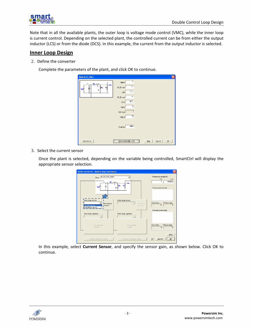
Note that in all the available plants, the outer loop is voltage mode control (VMC), while the inner loop is current control. Depending on the selected plant, the controlled current can be from either the output inductor (LCS) or from the diode (DCS). In this example, the current from the output inductor is selected.
Inner Loop Design
2. Define the converter
Complete the parameters of the plant, and click OK to continue.
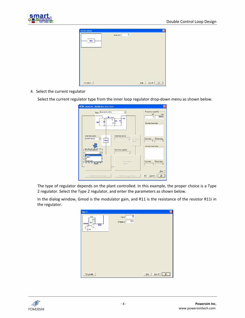
3. Select the current sensor
Once the plant is selected, depending on the variable being controlled, SmartCtrl will display the appropriate sensor selection.
In this example, select Current Sensor, and specify the sensor gain, as shown below. Click OK to continue.
Double Control Loop Design
‐ 4 ‐ Powersim Inc. www.powersimtech.com
4. Select the current regulator
Select the current regulator type from the inner loop regulator drop‐down menu as shown below.
The type of regulator depends on the plant controlled. In this example, the proper choice is a Type 2 regulator. Select the Type 2 regulator, and enter the parameters as shown below.
In the dialog window, Gmod is the modulator gain, and R11 is the resistance of the resistor R11i in the regulator.
Double Control Loop Design
‐ 5 ‐ Powersim Inc. www.powersimtech.com
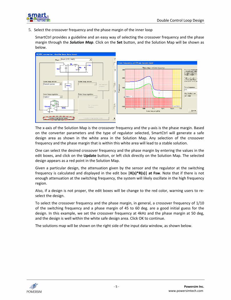
5. Select the crossover frequency and the phase margin of the inner loop
SmartCtrl provides a guideline and an easy way of selecting the crossover frequency and the phase margin through the Solution Map. Click on the Set button, and the Solution Map will be shown as below.
The x‐axis of the Solution Map is the crossover frequency and the y‐axis is the phase margin. Based on the converter parameters and the type of regulator selected, SmartCtrl will generate a safe design area as shown in the white area in the Solution Map. Any selection of the crossover frequency and the phase margin that is within this white area will lead to a stable solution.
One can select the desired crossover frequency and the phase margin by entering the values in the edit boxes, and click on the Update button, or left click directly on the Solution Map. The selected design appears as a red point in the Solution Map.
Given a particular design, the attenuation given by the sensor and the regulator at the switching frequency is calculated and displayed in the edit box |K(s)*R(s)| at Fsw. Note that if there is not enough attenuation at the switching frequency, the system will likely oscillate in the high frequency region.
Also, if a design is not proper, the edit boxes will be change to the red color, warning users to re‐select the design.
To select the crossover frequency and the phase margin, in general, a crossover frequency of 1/10 of the switching frequency and a phase margin of 45 to 60 deg. are a good initial guess for the design. In this example, we set the crossover frequency at 4kHz and the phase margin at 50 deg, and the design is well within the white safe design area. Click OK to continue.
The solutions map will be shown on the right side of the input data window, as shown below.
Double Control Loop Design
‐ 6 ‐ Powersim Inc. www.powersimtech.com
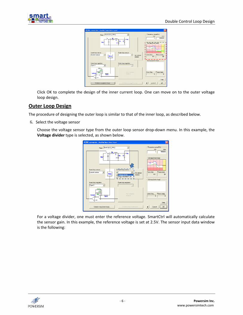
Click OK to complete the design of the inner current loop. One can move on to the outer voltage loop design.
Outer Loop Design
The procedure of designing the outer loop is similar to that of the inner loop, as described below.
6. Select the voltage sensor
Choose the voltage sensor type from the outer loop sensor drop‐down menu. In this example, the Voltage divider type is selected, as shown below.
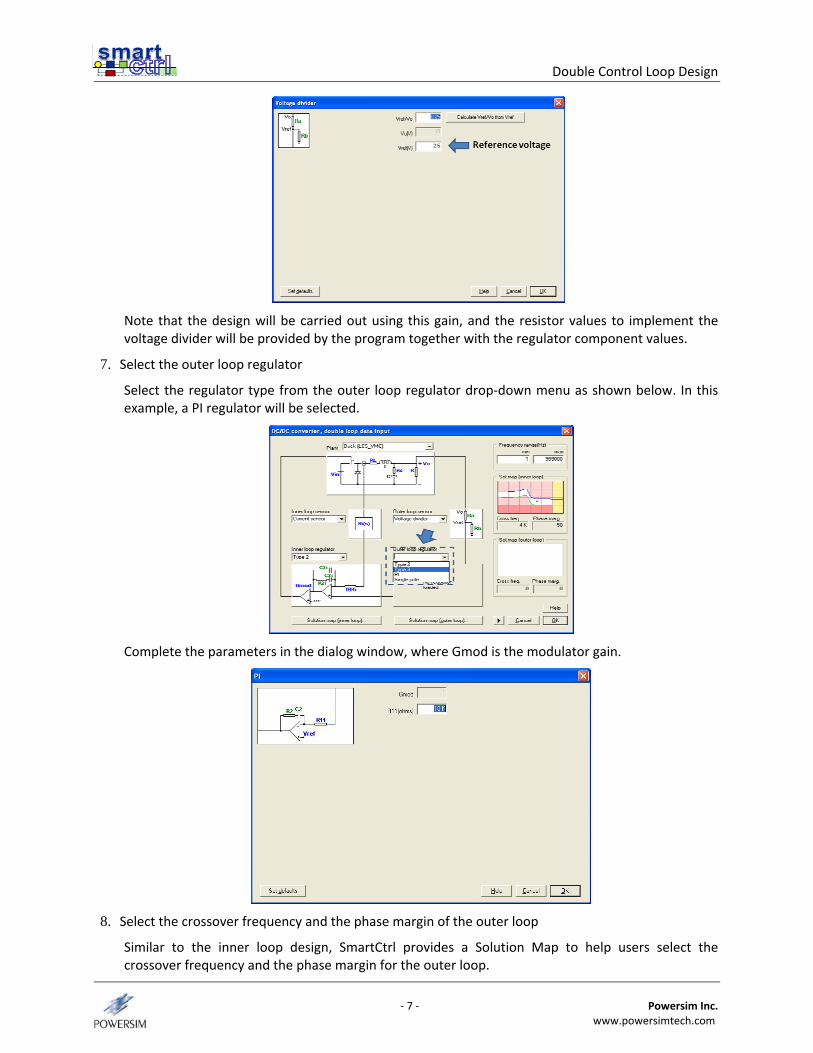
For a voltage divider, one must enter the reference voltage. SmartCtrl will automatically calculate the sensor gain. In this example, the reference voltage is set at 2.5V. The sensor input data window is the following:
Double Control Loop Design
‐ 7 ‐ Powersim Inc. www.powersimtech.com
Note that the design will be carried out using this gain, and the resistor values to implement the voltage divider will be provided by the program together with the regulator component values.
7. Select the outer loop regulator
Select the regulator type from the outer loop regulator drop‐down menu as shown below. In this example, a PI regulator will be selected.
Complete the parameters in the dialog window, where Gmod is the modulator gain.
8. Select the crossover frequency and the phase margin of the outer loop
Similar to the inner loop design, SmartCtrl provides a Solution Map to help users select the crossover frequency and the phase margin for the outer loop.
Double Control Loop Design
‐ 8 ‐ Powersim Inc. www.powersimtech.com
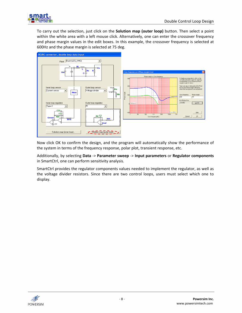
To carry out the selection, just click on the Solution map (outer loop) button. Then select a point within the white area with a left mouse click. Alternatively, one can enter the crossover frequency and phase margin values in the edit boxes. In this example, the crossover frequency is selected at 600Hz and the phase margin is selected at 75 deg.
Now click OK to confirm the design, and the program will automatically show the performance of the system in terms of the frequency response, polar plot, transient response, etc.
Additionally, by selecting Data ‐> Parameter sweep ‐> Input parameters or Regulator components in SmartCtrl, one can perform sensitivity analysis.
SmartCtrl provides the regulator components values needed to implement the regulator, as well as the voltage divider resistors. Since there are two control loops, users must select which one to display.
Double Control Loop Design
‐ 9 ‐ Powersim Inc. www.powersimtech.com
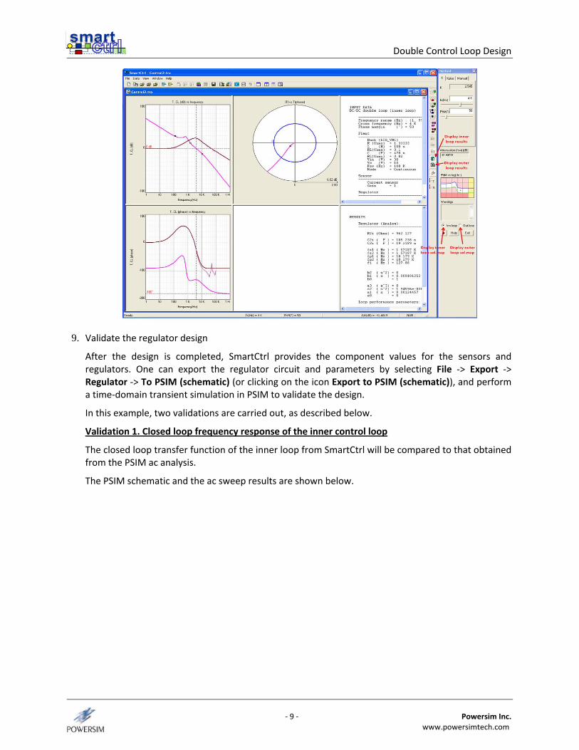
9. Validate the regulator design
After the design is completed, SmartCtrl provides the component values for the sensors and regulators. One can export the regulator circuit and parameters by selecting File ‐> Export ‐> Regulator ‐> To PSIM (schematic) (or clicking on the icon Export to PSIM (schematic)), and perform a time‐domain transient simulation in PSIM to validate the design.
In this example, two validations are carried out, as described below.
Validation 1. Closed loop frequency response of the inner control loop
The closed loop transfer function of the inner loop from SmartCtrl will be compared to that obtained from the PSIM ac analysis.
The PSIM schematic and the ac sweep results are shown below.
Double Control Loop Design
‐ 10 ‐ Powersim Inc. www.powersimtech.com
AC perturbation
AC voltmeter
AC sweep
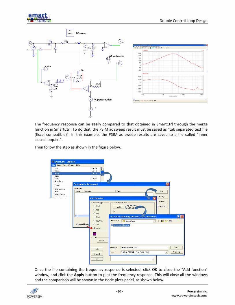
The frequency response can be easily compared to that obtained in SmartCtrl through the merge function in SmartCtrl. To do that, the PSIM ac sweep result must be saved as “tab separated text file (Excel compatible)”. In this example, the PSIM ac sweep results are saved to a file called “inner closed loop.txt”.
Then follow the step as shown in the figure below.
Closed loop
Once the file containing the frequency response is selected, click OK to close the “Add function” window, and click the Apply button to plot the frequency response. This will close all the windows and the comparison will be shown in the Bode plots panel, as shown below.
Double Control Loop Design
‐ 11 ‐ Powersim Inc. www.powersimtech.com
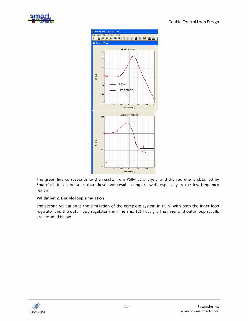
The green line corresponds to the results from PSIM ac analysis, and the red one is obtained by SmartCtrl. It can be seen that these two results compare well, especially in the low‐frequency region.
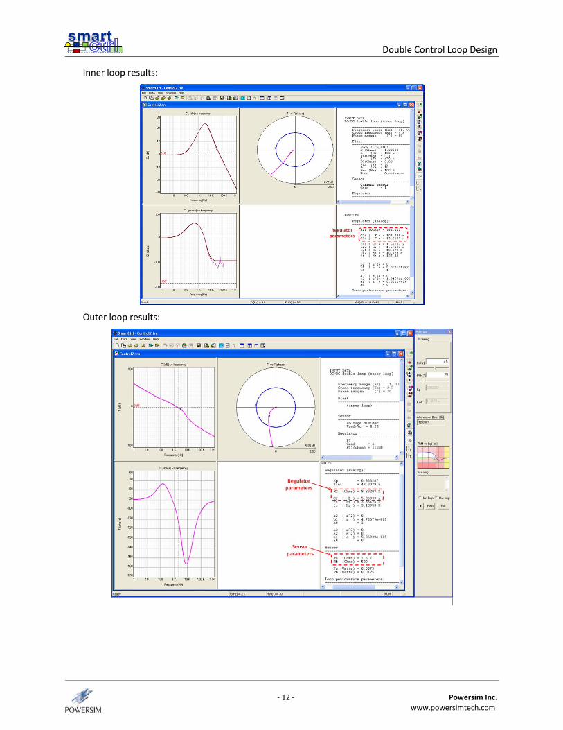
Validation 2. Double loop simulation
The second validation is the simulation of the complete system in PSIM with both the inner loop regulator and the outer loop regulator from the SmartCtrl design. The inner and outer loop results are included below.
Double Control Loop Design
‐ 12 ‐ Powersim Inc. www.powersimtech.com
Inner loop results:
Outer loop results:
Double Control Loop Design
‐ 13 ‐ Powersim Inc. www.powersimtech.com
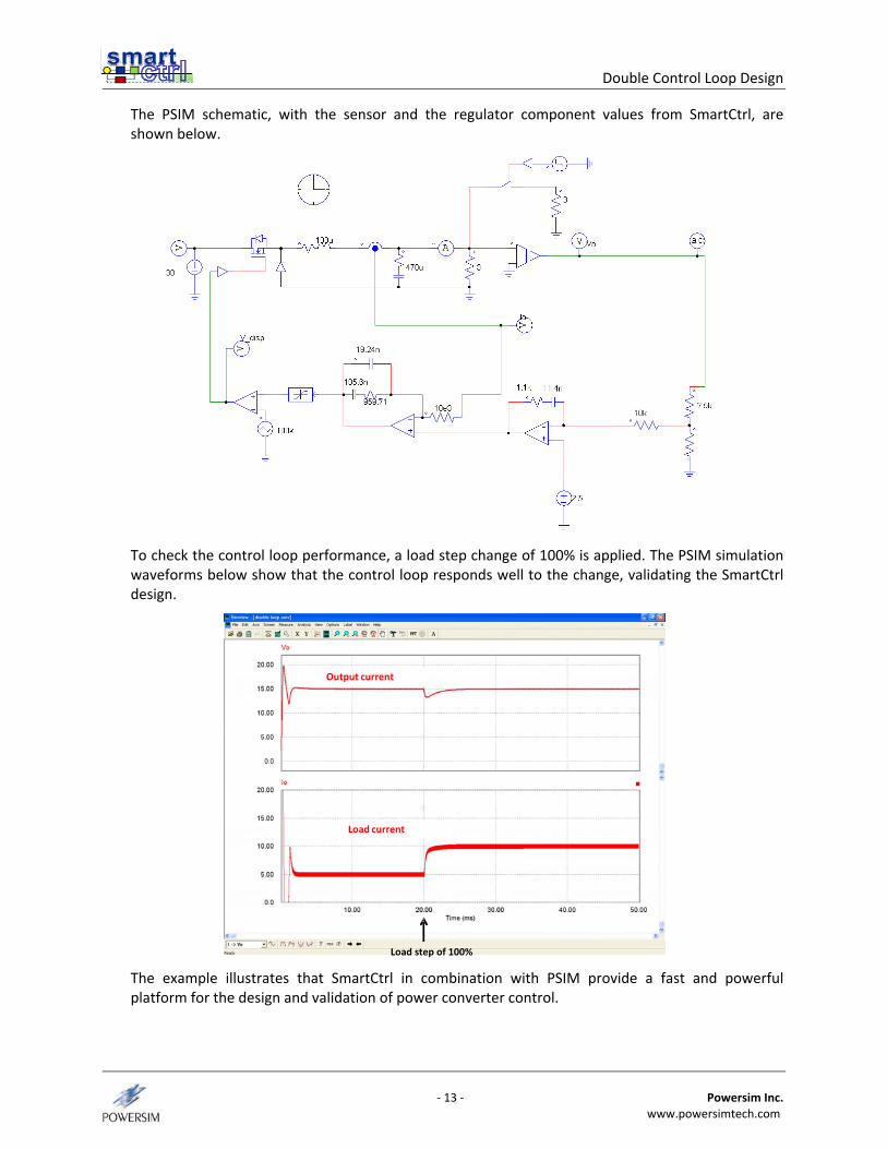
The PSIM schematic, with the sensor and the regulator component values from SmartCtrl, are shown below.
To check the control loop performance, a load step change of 100% is applied. The PSIM simulation waveforms below show that the control loop responds well to the change, validating the SmartCtrl design.
Load current
Load step of 100%
Output current
The example illustrates that SmartCtrl in combination with PSIM provide a fast and powerful platform for the design and validation of power converter control.