Embed Size (px)
Citation preview
8/9/2019 Uart Spi i2c Tuto
http://slidepdf.com/reader/full/uart-spi-i2c-tuto 1/17
AN10369UART/SPI/I2C code examples
Rev. 01 — 06 April 2005 Application note
Document information
Info Content
Keywords UART, SPI, I2C
Abstract Simple code examples are provided for UART0, SPI and I2C.
8/9/2019 Uart Spi i2c Tuto
http://slidepdf.com/reader/full/uart-spi-i2c-tuto 2/17
Philips Semiconductors AN10369Philips ARM LPC microcontroller family
Revision history
Rev Date Description
01 20050406 Initial version
Contact information
For additional information, please visit: http://www.semiconductors.philips.com
For sales office addresses, please send an email to: [email protected]
© Koninklijke Philips Electronics N.V. 2005. All rights reserved.
Application note Rev. 01 — 06 April 2005 2 of 17
8/9/2019 Uart Spi i2c Tuto
http://slidepdf.com/reader/full/uart-spi-i2c-tuto 3/17
Philips Semiconductors AN10369 Philips ARM LPC microcontroller family
1. Introduction
This application note provides code samples, which will enable the user to get a jump-
start into using some of the serial communication interfaces of the LPC2000 family. Inthis application note code samples are provided for UART0, SPI and I
2C-bus. For
detailed description on the peripheral please refer to the User manual of the respective
device.
The basic startup assembly code is only shown for the I2C-bus peripheral. For UART0
and SPI, the basic startup code should setup the stack pointer for the Supervisor mode,
which could be done using the LDR (Load Register) instruction.
LDR SP, =0x4..
The code was tested on a LPC2106 evaluation board, which uses a 10 MHz crystal
(system clock). The on-chip PLL has not been used for the sample code examples given
below. If the user uses the code for a different crystal setting then be sure to set the baudrate/speed of the peripheral accordingly before running the example code. Speed
calculations equations are provided for each peripheral. All the code samples are
configured to run from SRAM and they were compiled using the ADS (ARM Development
Suite) v1.2 compiler.
Though the below code samples have been successfully tested on the LPC2106 it
should work fine on rest of the Philips LPC2000 family devices after some minor
modifications. Minor modifications could be setting the Stack pointer correctly (depending
upon the SRAM present on chip), using the correct header files etc. If the end user
wishes to run the code from the on-chip Flash then a signature is to be placed at 0x14
and the code has to be linked differently in addition to other changes.
2. UART0
The below code sample configures UART0 to interface to a Terminal program running on
a host machine (maybe Tera Term Or HyperTerminal) at a baud rate of 9600. The code
simply prints “Philips LPC” on the host machine terminal program forever since it is
included in a while (1) loop. VPB Divider value is at its reset settings and hence the
peripheral clock is one fourth of the system clock. The VPB clock would then be 2.5MHz.
Steps on calculating the divisor value are shown below.
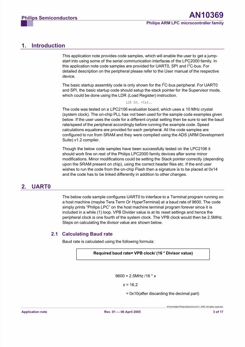
Required baud rate= VPB clock/ (16 * Divisor value)
2.1 Calculating Baud rate
Baud rate is calculated using the following formula:
9600 = 2.5MHz /16 * x
x = 16.2
= 0x10(after discarding the decimal part)
© Koninklijke Philips Electronics N.V. 2005. All rights reserved.
Application note Rev. 01 — 06 April 2005 3 of 17
8/9/2019 Uart Spi i2c Tuto
http://slidepdf.com/reader/full/uart-spi-i2c-tuto 4/17
Philips Semiconductors AN10369 Philips ARM LPC microcontroller family
This value needs to be entered into the U0DLL register as shown below.
2.2 C Code/* Include header file depending upon device been used */#include"LPC2….h"
void Initialize(void);
/* Macro Definitions */#define TEMT (1<<6)#define LINE_FEED 0xA#define CARRIAGE_RET 0xD
/************************* MAIN *************************/
int main(){
int i;char c[]="Philips LPC";
Initialize()
/* Print forever */while(1)
{i=0;
/* Keep Transmitting until Null character('\0') is reached */while(c[i])
{U0THR=c[i];i++;
}
U0THR=LINE_FEED;U0THR=CARRAIGE_RET;
/* Wait till U0THR and U0TSR are both empty */while(!(U0LSR & TEMT)){}
}
}
/*************** System Initialization ***************/void Initialize()
{/* Initialize Pin Select Block for Tx and Rx */PINSEL0=0x5;
/* Enable FIFO's and reset them */U0FCR=0x7;
/* Set DLAB and word length set to 8bits */U0LCR=0x83;
© Koninklijke Philips Electronics N.V. 2005. All rights reserved.
Application note Rev. 01 — 06 April 2005 4 of 17
8/9/2019 Uart Spi i2c Tuto
http://slidepdf.com/reader/full/uart-spi-i2c-tuto 5/17
Philips Semiconductors AN10369 Philips ARM LPC microcontroller family
/* Baud rate set to 9600 */U0DLL=0x10;U0DLM=0x0;
/* Clear DLAB */U0LCR=0x3;
}/*********************************************************/
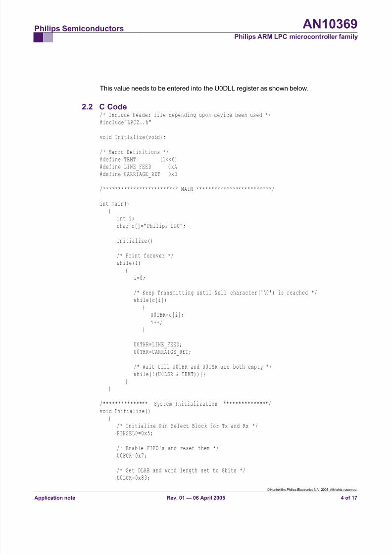
2.3 Terminal Program settings
This code was tested on Tera Term Pro v2.3 and the settings for the serial port are
shown below.
Fig 1. Tera Term serial port settings
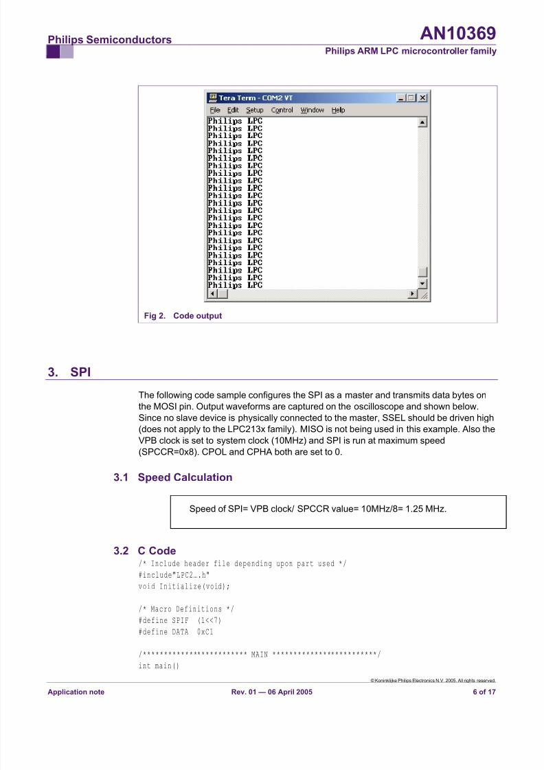
2.4 Output
The output of the above code should be similar to the screen shown in Fig 2.
© Koninklijke Philips Electronics N.V. 2005. All rights reserved.
Application note Rev. 01 — 06 April 2005 5 of 17
8/9/2019 Uart Spi i2c Tuto
http://slidepdf.com/reader/full/uart-spi-i2c-tuto 6/17
Philips Semiconductors AN10369 Philips ARM LPC microcontroller family
Fig 2. Code output
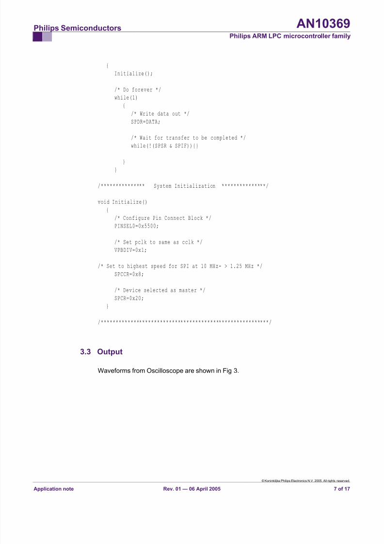
3. SPI
The following code sample configures the SPI as a master and transmits data bytes on
the MOSI pin. Output waveforms are captured on the oscilloscope and shown below.Since no slave device is physically connected to the master, SSEL should be driven high
(does not apply to the LPC213x family). MISO is not being used in this example. Also the
VPB clock is set to system clock (10MHz) and SPI is run at maximum speed
(SPCCR=0x8). CPOL and CPHA both are set to 0.
3.1 Speed Calculation
Speed of SPI= VPB clock/ SPCCR value= 10MHz/8= 1.25 MHz.
© Koninklijke Philips Electronics N.V. 2005. All rights reserved.
Application note Rev. 01 — 06 April 2005 6 of 17
3.2 C Code/* Include header file depending upon part used */
#include"LPC2….h"
void Initialize(void);
/* Macro Definitions */
#define SPIF (1<<7)
#define DATA 0xC1
/************************* MAIN *************************/
int main()
8/9/2019 Uart Spi i2c Tuto
http://slidepdf.com/reader/full/uart-spi-i2c-tuto 7/17
Philips Semiconductors AN10369 Philips ARM LPC microcontroller family
{
Initialize();
/* Do forever */
while(1)
{
/* Write data out */
SPDR=DATA;
/* Wait for transfer to be completed */
while(!(SPSR & SPIF)){}
}
}
/*************** System Initialization ***************/
void Initialize()
{
/* Configure Pin Connect Block */
PINSEL0=0x5500;
/* Set pclk to same as cclk */
VPBDIV=0x1;
/* Set to highest speed for SPI at 10 MHz- > 1.25 MHz */
SPCCR=0x8;
/* Device selected as master */
SPCR=0x20;
}
/*********************************************************/
3.3 Output
Waveforms from Oscilloscope are shown in Fig 3.
© Koninklijke Philips Electronics N.V. 2005. All rights reserved.
Application note Rev. 01 — 06 April 2005 7 of 17

8/9/2019 Uart Spi i2c Tuto
http://slidepdf.com/reader/full/uart-spi-i2c-tuto 8/17
Philips Semiconductors AN10369 Philips ARM LPC microcontroller family
Fig 3. Waveforms
0xC1
4. I2C
In the above code examples for UART and SPI, interrupts have not been used but they
have been used for this example. I2C has been classified as an IRQ interrupt. LPC2106
is being used as a Master Transmitter and a Philips port expander PCF8574 is used as a
slave device. Waveforms are shown to help the user to understand the communication
better. VPB Divider value is at its reset settings and hence the peripheral clock is one
fourth of the system clock (10 MHz).
4.1 Calculation of Bit frequency
Bit Frequency = pclk/ (I2CSCLH + I
2CSCLL)
Since the maximum speed the PCF8574 could interface to the LPC2106 is100 KHz
100KHz= 2.5MHz/(I2CSCLH + I2CSCLL)
Therefore
I2CSCLH + I
2CSCLL=25
We select
I2CSCLH=13
&
I2CSCLL=12
© Koninklijke Philips Electronics N.V. 2005. All rights reserved.
Application note Rev. 01 — 06 April 2005 8 of 17
8/9/2019 Uart Spi i2c Tuto
http://slidepdf.com/reader/full/uart-spi-i2c-tuto 9/17
Philips Semiconductors AN10369 Philips ARM LPC microcontroller family
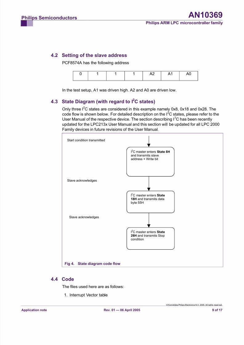
4.2 Setting of the slave address
PCF8574A has the following address
0 1 1 1 A2 A1 A0
In the test setup, A1 was driven high. A2 and A0 are driven low.
4.3 State Diagram (with regard to I2C states)
Only three I2C states are considered in this example namely 0x8, 0x18 and 0x28. The
code flow is shown below. For detailed description on the I2C states, please refer to the
User Manual of the respective device. The section describing I
2
C has been recentlyupdated for the LPC213x User Manual and this section will be updated for all LPC 2000
Family devices in future revisions of the User Manual.
Start condition transmitted
Fig 4. State diagram code flow
I2C master enters State 8H
and transmits slaveaddress + Write bit
Slave acknowledges
Slave acknowledges
I2C master enters State
28H and transmits Stopcondition
I C master enters State18H and transmits databyte 55H
4.4 Code
The files used here are as follows:
1. Interrupt Vector table
© Koninklijke Philips Electronics N.V. 2005. All rights reserved.
Application note Rev. 01 — 06 April 2005 9 of 17

8/9/2019 Uart Spi i2c Tuto
http://slidepdf.com/reader/full/uart-spi-i2c-tuto 10/17
Philips Semiconductors AN10369 Philips ARM LPC microcontroller family
2. Startup Assembly code
3. Main C file
4. Header file
5. Tool specific file (not shown here)
Only the first three files are discussed and shown below.
4.4.1 Interrupt Vector table
; ---------------------------------------------------------
; Assembler Directives
; ---------------------------------------------------------
AREA IVT, CODE ; New Code section
CODE32 ; ARM code
IMPORT start ; start symbol not
; defined in this
; section
Entry ; Defines entry point
; ---------------------------------------------------------
LDR PC, =start
LDR PC, Undefined_Addr
LDR PC, SWI_Addr
LDR PC, Prefetch_Addr
LDR PC, Abort_Addr
NOP
LDR PC, [PC, #-0xFF0]
LDR PC, FIQ_Addr
Undefined_Addr DCD Undefined_Handler
SWI_Addr DCD SWI_Handler
Prefetch_Addr DCD Prefetch_Handler
Abort_Addr DCD Abort_Handler
FIQ_Addr DCD FIQ_Handler
; ---------------------------------------------------------
; Exception Handlers
; ---------------------------------------------------------
; The following dummy handlers do not do anything useful in
; this example. They are set up here for completeness.
Undefined_Handler
B Undefined_Handler
SWI_Handler
B SWI_Handler
Prefetch_Handler
B Prefetch_Handler
Abort_Handler
B Abort_Handler
© Koninklijke Philips Electronics N.V. 2005. All rights reserved.
Application note Rev. 01 — 06 April 2005 10 of 17
8/9/2019 Uart Spi i2c Tuto
http://slidepdf.com/reader/full/uart-spi-i2c-tuto 11/17
Philips Semiconductors AN10369 Philips ARM LPC microcontroller family
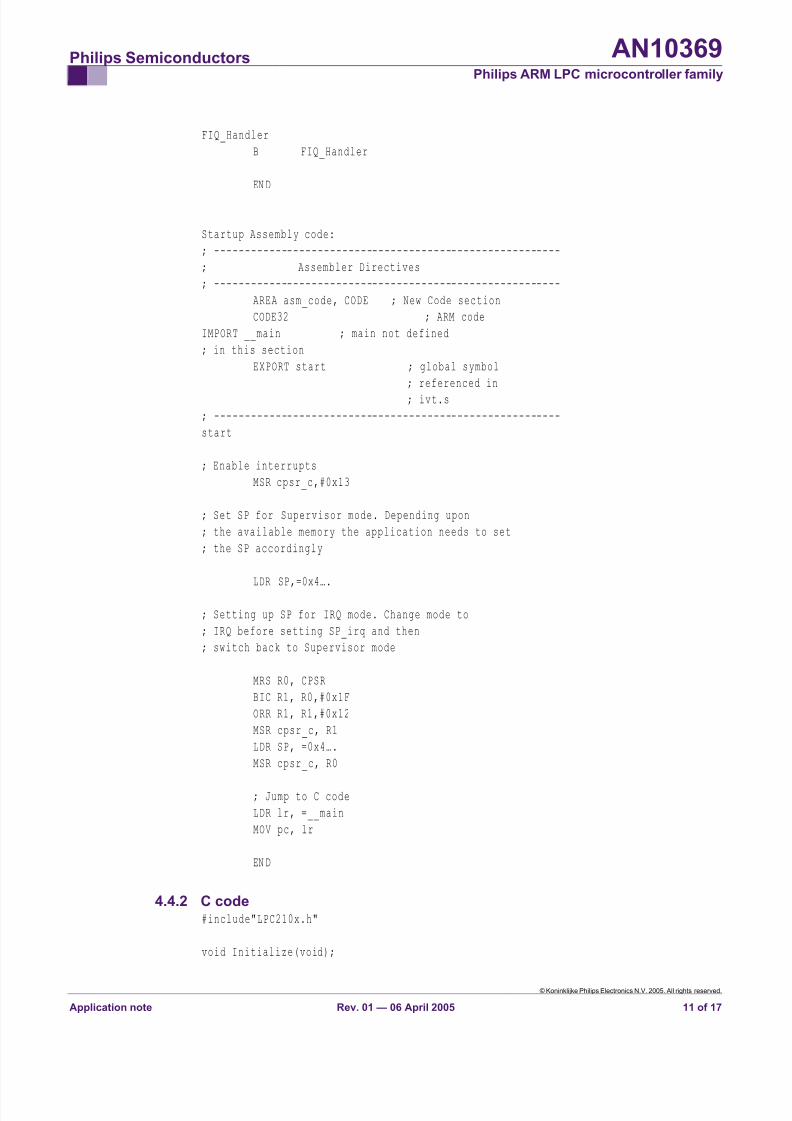
FIQ_Handler
B FIQ_Handler
END
Startup Assembly code:
; ---------------------------------------------------------
; Assembler Directives
; ---------------------------------------------------------
AREA asm_code, CODE ; New Code section
CODE32 ; ARM code
IMPORT __main ; main not defined
; in this section
EXPORT start ; global symbol
; referenced in
; ivt.s
; ---------------------------------------------------------
start
; Enable interrupts
MSR cpsr_c,#0x13
; Set SP for Supervisor mode. Depending upon
; the available memory the application needs to set
; the SP accordingly
LDR SP,=0x4….
; Setting up SP for IRQ mode. Change mode to
; IRQ before setting SP_irq and then
; switch back to Supervisor mode
MRS R0, CPSR
BIC R1, R0,#0x1F
ORR R1, R1,#0x12
MSR cpsr_c, R1
LDR SP, =0x4….
MSR cpsr_c, R0
; Jump to C code
LDR lr, =__main
MOV pc, lr
END
4.4.2 C code#include"LPC210x.h"
void Initialize(void);
© Koninklijke Philips Electronics N.V. 2005. All rights reserved.
Application note Rev. 01 — 06 April 2005 11 of 17
8/9/2019 Uart Spi i2c Tuto
http://slidepdf.com/reader/full/uart-spi-i2c-tuto 12/17
Philips Semiconductors AN10369 Philips ARM LPC microcontroller family
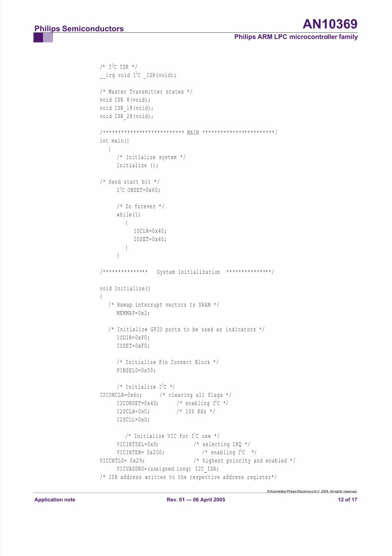
/* I2C ISR */
__irq void I2C _ISR(void);
/* Master Transmitter states */
void ISR_8(void);
void ISR_18(void);
void ISR_28(void);
/*************************** MAIN ************************/
int main()
{
/* Initialize system */
Initialize ();
/* Send start bit */
I2C ONSET=0x60;
/* Do forever */
while(1)
{
IOCLR=0x40;
IOSET=0x40;
}
}
/*************** System Initialization ***************/
void Initialize()
{
/* Remap interrupt vectors to SRAM */
MEMMAP=0x2;
/* Initialize GPIO ports to be used as indicators */
IODIR=0xF0;
IOSET=0xF0;
/* Initialize Pin Connect Block */
PINSEL0=0x50;
/* Initialize I
2
C */I2CONCLR=0x6c; /* clearing all flags */
I2CONSET=0x40; /* enabling I2C */
I2SCLH=0xC; /* 100 KHz */
I2SCLL=0xD;
/* Initialize VIC for I 2C use */
VICINTSEL=0x0; /* selecting IRQ */
VICINTEN= 0x200; /* enabling I2C */
VICCNTL0= 0x29; /* highest priority and enabled */
VICVADDR0=(unsigned long) I2C_ISR;
/* ISR address written to the respective address register*/
© Koninklijke Philips Electronics N.V. 2005. All rights reserved.
Application note Rev. 01 — 06 April 2005 12 of 17
8/9/2019 Uart Spi i2c Tuto
http://slidepdf.com/reader/full/uart-spi-i2c-tuto 13/17
Philips Semiconductors AN10369 Philips ARM LPC microcontroller family
}
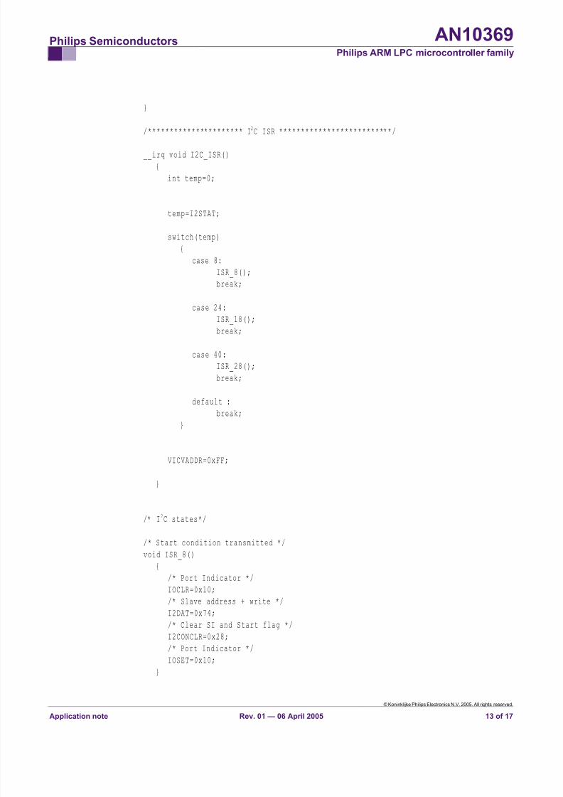
/********************** I2C ISR **************************/
__irq void I2C_ISR()
{
int temp=0;
temp=I2STAT;
switch(temp)
{
case 8:
ISR_8();
break;
case 24:
ISR_18();
break;
case 40:
ISR_28();
break;
default :
break;
}
VICVADDR=0xFF;
}
/* I2C states*/
/* Start condition transmitted */
void ISR_8(){
/* Port Indicator */
IOCLR=0x10;
/* Slave address + write */
I2DAT=0x74;
/* Clear SI and Start flag */
I2CONCLR=0x28;
/* Port Indicator */
IOSET=0x10;
}
© Koninklijke Philips Electronics N.V. 2005. All rights reserved.
Application note Rev. 01 — 06 April 2005 13 of 17
8/9/2019 Uart Spi i2c Tuto
http://slidepdf.com/reader/full/uart-spi-i2c-tuto 14/17
Philips Semiconductors AN10369 Philips ARM LPC microcontroller family
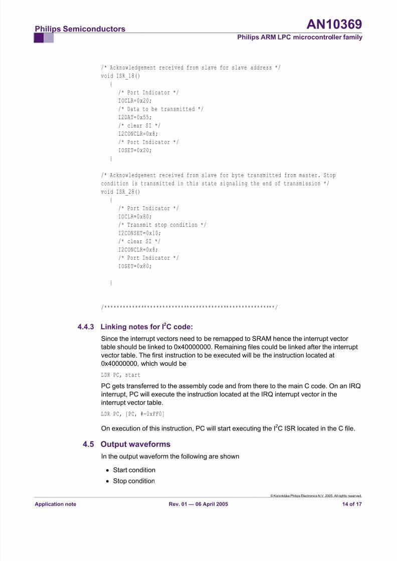
/* Acknowledgement received from slave for slave address */
void ISR_18()
{
/* Port Indicator */
IOCLR=0x20;
/* Data to be transmitted */
I2DAT=0x55;
/* clear SI */
I2CONCLR=0x8;
/* Port Indicator */
IOSET=0x20;
}
/* Acknowledgement received from slave for byte transmitted from master. Stop
condition is transmitted in this state signaling the end of transmission */
void ISR_28()
{
/* Port Indicator */
IOCLR=0x80;
/* Transmit stop condition */
I2CONSET=0x10;
/* clear SI */
I2CONCLR=0x8;
/* Port Indicator */
IOSET=0x80;
}
/********************************************************/
4.4.3 Linking notes for I2C code:
Since the interrupt vectors need to be remapped to SRAM hence the interrupt vector
table should be linked to 0x40000000. Remaining files could be linked after the interrupt
vector table. The first instruction to be executed will be the instruction located at
0x40000000, which would be
LDR PC, start
PC gets transferred to the assembly code and from there to the main C code. On an IRQ
interrupt, PC will execute the instruction located at the IRQ interrupt vector in theinterrupt vector table.
LDR PC, [PC, #-0xFF0]
On execution of this instruction, PC will start executing the I2C ISR located in the C file.
4.5 Output waveforms
In the output waveform the following are shown
• Start condition
• Stop condition
© Koninklijke Philips Electronics N.V. 2005. All rights reserved.
Application note Rev. 01 — 06 April 2005 14 of 17
8/9/2019 Uart Spi i2c Tuto
http://slidepdf.com/reader/full/uart-spi-i2c-tuto 15/17
Philips Semiconductors AN10369 Philips ARM LPC microcontroller family
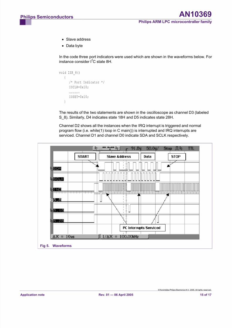
• Slave address
• Data byte
In the code three port indicators were used which are shown in the waveforms below. For instance consider I
2C state 8H.
void ISR_8()
{
/* Port Indicator */
IOCLR=0x10;
…………….
IOSET=0x10;
}
The results of the two statements are shown in the oscilloscope as channel D3 (labeled
S_8). Similarly, D4 indicates state 18H and D5 indicates state 28H.
Channel D2 shows all the instances when the IRQ interrupt is triggered and normal
program flow (i.e. while(1) loop in C main()) is interrupted and IRQ interrupts are
serviced. Channel D1 and channel D0 indicate SDA and SCLK respectively.
Fig 5. Waveforms
© Koninklijke Philips Electronics N.V. 2005. All rights reserved.
Application note Rev. 01 — 06 April 2005 15 of 17
8/9/2019 Uart Spi i2c Tuto
http://slidepdf.com/reader/full/uart-spi-i2c-tuto 16/17
Philips Semiconductors AN10369Philips ARM LPC microcontroller family
5. Disclaimers
Life support — These products are not designed for use in life support
appliances, devices, or systems where malfunction of these products can
reasonably be expected to result in personal injury. Philips Semiconductors
customers using or selling these products for use in such applications do so
at their own risk and agree to fully indemnify Philips Semiconductors for any
damages resulting from such application.
Right to make changes — Philips Semiconductors reserves the right to
make changes in the products - including circuits, standard cells, and/or
software - described or contained herein in order to improve design and/or
performance. When the product is in full production (status ‘Production’),
relevant changes will be communicated via a Customer Product/Process
Change Notification (CPCN). Philips Semiconductors assumes no
responsibility or liability for the use of any of these products, conveys no
licence or title under any patent, copyright, or mask work right to these
products, and makes no representations or warranties that these products
are free from patent, copyright, or mask work right infringement, unlessotherwise specified.
Application information — Applications that are described herein for any of
these products are for illustrative purposes only. Philips Semiconductors
make no representation or warranty that such applications will be suitable for
the specified use without further testing or modification.
© Koninklijke Philips Electronics N.V. 2005. All rights reserved.
Application note Rev. 01 — 06 April 2005 16 of 17
8/9/2019 Uart Spi i2c Tuto
http://slidepdf.com/reader/full/uart-spi-i2c-tuto 17/17
Philips Semiconductors AN10369 Philips ARM LPC microcontroller family
6. Contents
1. Introduction .........................................................3 2. UART0 ..................................................................3 2.1 Calculating Baud rate..........................................3 2.2 C Code................................................................4 2.3 Terminal Program settings..................................5 2.4 Output .................................................................5 3. SPI ........................................................................6 3.1 Speed Calculation...............................................6 3.2 C Code................................................................6 3.3 Output .................................................................7 4. I
2C ......................................................................... 8
4.1 Calculation of Bit frequency ................................ 8 4.2 Setting of the slave address................................9 4.3 State Diagram (with regard to I
2C states)............9
4.4 Code ...................................................................9 4.4.1 Interrupt Vector table ........................................ 10 4.4.2 C code ..............................................................11 4.4.3 Linking notes for I
2C code: ................................ 14
4.5 Output waveforms.............................................14 5. Disclaimers ........................................................16 6. Contents.............................................................17
© Koninklijke Philips Electronics N.V. 2005
All rights are reserved. Reproduction in whole or in part is prohibited without the prior written consent of the copyright owner. The information presented in this document doesnot form part of any quotation or contract, is believed to be accurate and reliable and maybe changed without notice. No liability will be accepted by the publisher for anyconsequence of its use. Publication thereof does not convey nor imply any license under
patent- or other industrial or intellectual property rights.
Date of release: 06 April 2005


![Osciloscopio Digital de 100MHZ 2[4] canales … · Buses serie: Opción HOO10 I2C/SPI/UART/RS-232 en canales lógicos y canales analógicos Opción HOO11 I2C/SPI/UART/RS-232 en canales](https://img.pdfslide.tips/doc/110x75/5bb1ab5709d3f255638db18b/osciloscopio-digital-de-100mhz-24-canales-buses-serie-opcion-hoo10-i2cspiuartrs-232.jpg)


![[Codientu.org] Uart](https://img.pdfslide.tips/doc/110x75/55cf9ad7550346d033a3a8db/codientuorg-uart.jpg)