Embed Size (px)
Citation preview
8/10/2019 UGE_3.pdf
http://slidepdf.com/reader/full/uge3pdf 1/21
CAM Tutorial CREO PARAMETRIC 1.0 week 3 Part 6
Revised by Tomas Benzon DTU MEK March 2012 on basis of original COACH material Page 1
PART 6: SURFACE MILLING
CONVENTIONAL SURFACE MILL
Create a tool path to machine the top faces (shown in cyan below) of the provided mold insert.
1. Open the manufacturing model called: surf1.asm
2. Use the existing NC Sequence.
● In the Model tree, rightclick 1. Surface Mill ing [OP 010] and choose Edit Definit ion. ● In the Menu Manager choose Seq Setup.
● In the Seq Setup walk-through menu list, activate Surfaces and Define Cut (pre-chosen)
● Choose Done
Before starting this tutorial:
Ensure that you have downloaded all CAM files from the write-protected drive(R:\Kurser\CAM-42817\cam1_mm\) and placed them on your own drive (I:\)
Set the Working Directory to the directory on your own drive where you placed the CAMfiles.
8/10/2019 UGE_3.pdf
http://slidepdf.com/reader/full/uge3pdf 2/21
CAM Tutorial CREO PARAMETRIC 1.0 week 3 Part 6
Revised by Tomas Benzon DTU MEK March 2012 on basis of original COACH material Page 2
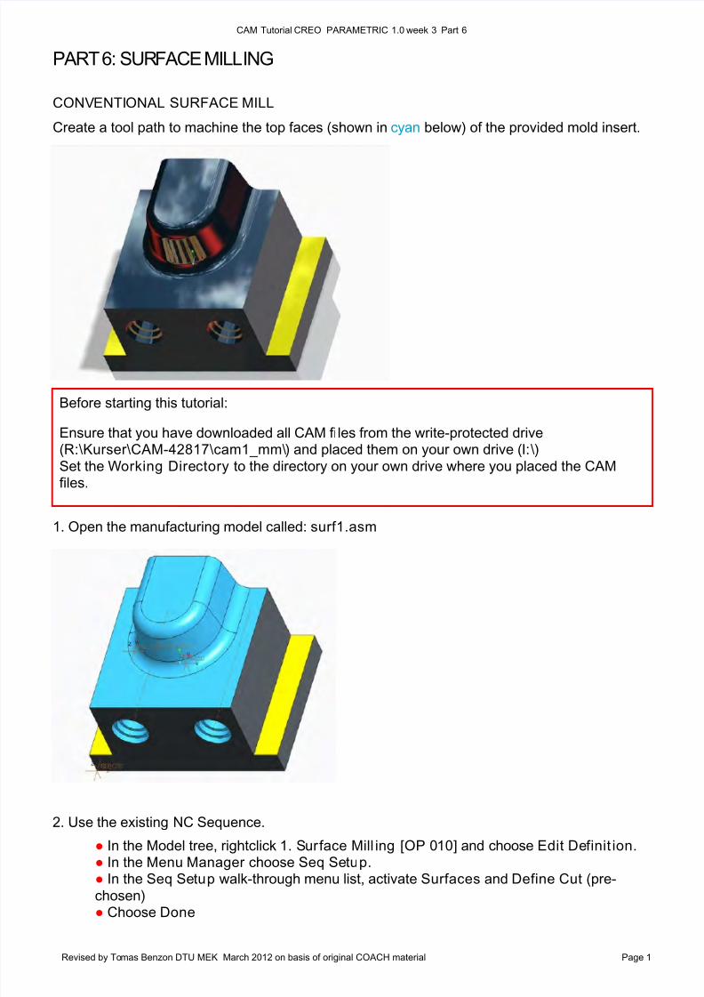
The order in which you select
them is not important. To select
more than one surface, you must
hold down the CTRL key as you
select.
Here all the top surfaces are
chosen
Note: This NC Sequence is setup using a 3-axis mill with a 25 mm diameter ball nose end mill tool. The other
important machining parameters that are preset include:
● Choose OK in the Select box ● Choose Done/Return - The Cut Definition Dialogue now appears...
4. Define the Cut Definition. In this case, you are going to use the default choices...but you canPreview the result of these settings.
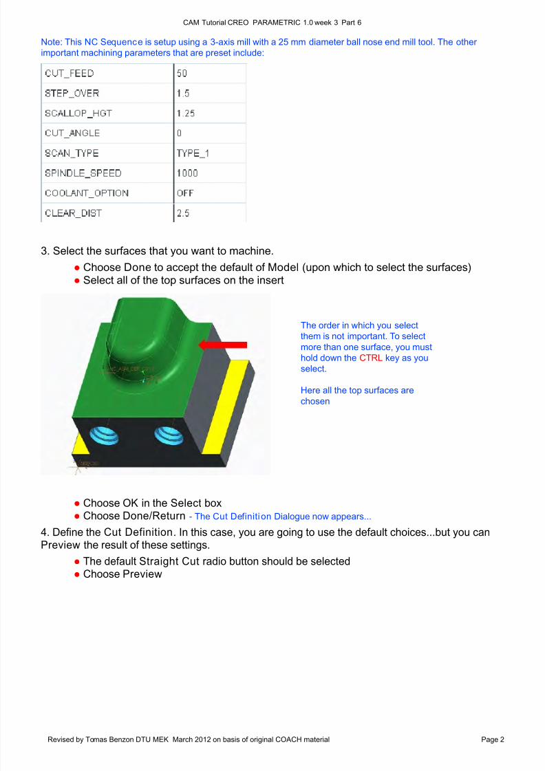
● The default Straight Cut radio button should be selected ● Choose Preview
3. Select the surfaces that you want to machine.
● Choose Done to accept the default of Model (upon which to select the surfaces)● Select all of the top surfaces on the insert
8/10/2019 UGE_3.pdf
http://slidepdf.com/reader/full/uge3pdf 3/21
CAM Tutorial CREO PARAMETRIC 1.0 week 3 Part 6
Revised by Tomas Benzon DTU MEK March 2012 on basis of original COACH material Page 3
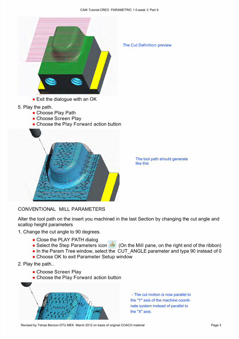
CONVENTIONAL MILL PARAMETERS
Alter the tool path on the insert you machined in the last Section by changing the cut angle andscallop height parameters
1. Change the cut angle to 90 degrees.
● Close the PLAY PATH dialog ● Select the Step Parameters icon (On the Mill pane, on the right end of the ribbon)
● In the Param Tree window, select the CUT_ANGLE parameter and type 90 instead of 0 ● Choose OK to exit Parameter Setup window
2. Play the path..
● Choose Screen Play ● Choose the Play Forward action button
- The cut motion is now parallel to
the "Y" axis of the machine coordi-
nate system instead of parallel to
the "X" axis.
● Exit the dialogue with an OK
5. Play the path. ● Choose Play Path
● Choose Screen Play ● Choose the Play Forward action button
The tool path should generatelike this
The Cut Definition preview
8/10/2019 UGE_3.pdf
http://slidepdf.com/reader/full/uge3pdf 4/21
CAM Tutorial CREO PARAMETRIC 1.0 week 3 Part 6
Revised by Tomas Benzon DTU MEK March 2012 on basis of original COACH material Page 4
Remember, the system checks the Step Over calculated from the Scallop Height specified in the Param Tree
window against the Step Over distance specified and uses the smaller number. If you increase the Scallop Height
and don't increase the Step Over number you may not see any change in the number of tool passes displayed.
Increase the Step Over parameter so it will not play a part in the calculations.
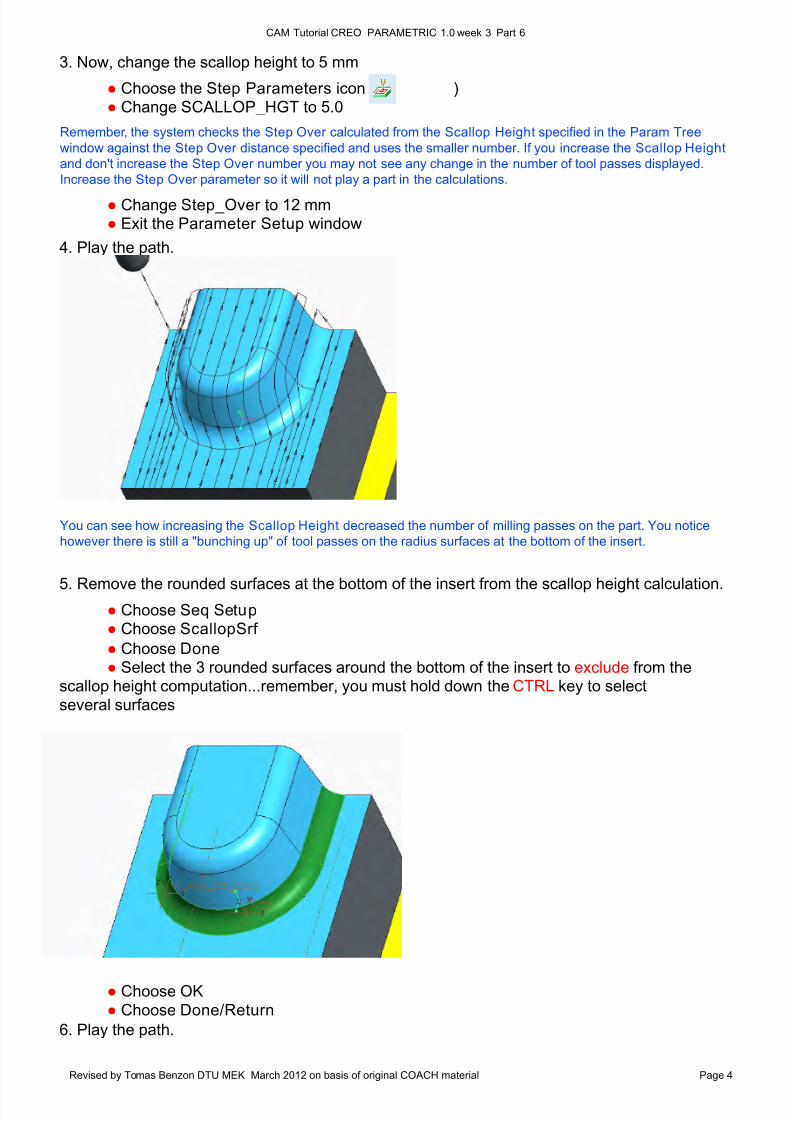
You can see how increasing the Scallop Height decreased the number of milling passes on the part. You notice
however there is still a "bunching up" of tool passes on the radius surfaces at the bottom of the insert.
3. Now, change the scallop height to 5 mm
● Choose the Step Parameters icon ( ) ● Change SCALLOP_HGT to 5.0
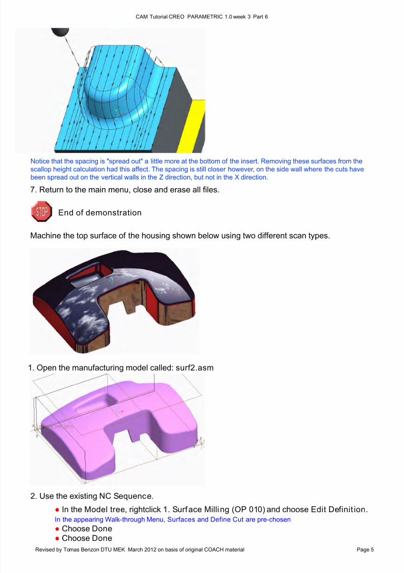
5. Remove the rounded surfaces at the bottom of the insert from the scallop height calculation. ● Choose Seq Setup
● Choose ScallopSrf
● Choose Done
● Select the 3 rounded surfaces around the bottom of the insert to exclude from thescallop height computation...remember, you must hold down the CTRL key to select
several surfaces
● Choose OK
● Choose Done/Return
6. Play the path.
● Change Step_Over to 12 mm ● Exit the Parameter Setup window
4. Play the path.
8/10/2019 UGE_3.pdf
http://slidepdf.com/reader/full/uge3pdf 5/21
CAM Tutorial CREO PARAMETRIC 1.0 week 3 Part 6
Revised by Tomas Benzon DTU MEK March 2012 on basis of original COACH material Page 5
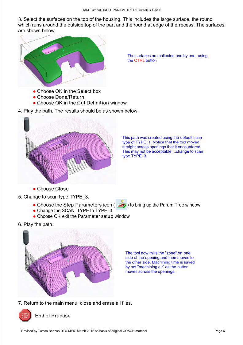
Notice that the spacing is "spread out" a little more at the bottom of the insert. Removing these surfaces from the
scallop height calculation had this affect. The spacing is still closer however, on the side wall where the cuts have
been spread out on the vertical walls in the Z direction, but not in the X direction.
7. Return to the main menu, close and erase all files.
End of demonstration
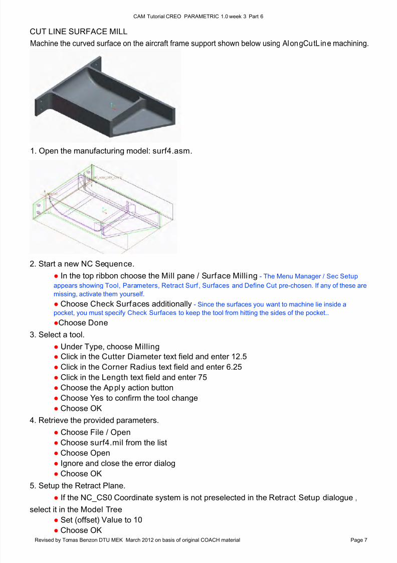
Machine the top surface of the housing shown below using two different scan types.
1. Open the manufacturing model called: surf2.asm
2. Use the existing NC Sequence.
● In the Model tree, rightclick 1. Surface Milling (OP 010) and choose Edit Definit ion. In the appearing Walk-through Menu, Surfaces and Define Cut are pre-chosen
● Choose Done ● Choose Done
8/10/2019 UGE_3.pdf
http://slidepdf.com/reader/full/uge3pdf 6/21
CAM Tutorial CREO PARAMETRIC 1.0 week 3 Part 6
Revised by Tomas Benzon DTU MEK March 2012 on basis of original COACH material Page 6
The surfaces are collected one by one, using
the CTRL button
This path was created using the default scantype of TYPE_1. Notice that the tool movedstraight across openings that it encountered.This may not be acceptable....change to scantype TYPE_3.
The tool now mills the "zone" on oneside of the opening and then moves tothe other side. Machining time is savedby not "machining air" as the cuttermoves across the openings.
3. Select the surfaces on the top of the housing. This includes the large surface, the roundwhich runs around the outside top of the part and the round at edge of the recess. The surfacesare shown below.
7. Return to the main menu, close and erase all files.
● Choose OK in the Select box
● Choose Done/Return
● Choose OK in the Cut Definit ion window
4. Play the path. The results should be as shown below.
● Choose Close
5. Change to scan type TYPE_3.
● Choose the Step Parameters icon ( ) to bring up the Param Tree window ● Change the SCAN_TYPE to TYPE_3 ● Choose OK exit the Parameter setup window
6. Play the path.
End of Practise
8/10/2019 UGE_3.pdf
http://slidepdf.com/reader/full/uge3pdf 7/21
CAM Tutorial CREO PARAMETRIC 1.0 week 3 Part 6
Revised by Tomas Benzon DTU MEK March 2012 on basis of original COACH material Page 7
CUT LINE SURFACE MILL
2. Start a new NC Sequence.
● In the top ribbon choose the Mill pane / Surface Milling - The Menu Manager / Sec Setup
appears showing Tool, Parameters, Retract Surf , Surfaces and Define Cut pre-chosen. If any of these are
missing, activate them yourself. ● Choose Check Surfaces additionally - Since the surfaces you want to machine lie inside a
pocket, you must specify Check Surfaces to keep the tool from hitting the sides of the pocket..
●Choose Done
3. Select a tool.
● Under Type, choose Milling
● Click in the Cutter Diameter text field and enter 12.5
● Click in the Corner Radius text field and enter 6.25
● Click in the Length text field and enter 75
● Choose the Apply action button
● Choose Yes to confirm the tool change
● Choose OK
4. Retrieve the provided parameters.
● Choose File / Open
● Choose surf4.mil from the list
● Choose Open
● Ignore and close the error dialog
● Choose OK
5. Setup the Retract Plane.
● If the NC_CS0 Coordinate system is not preselected in the Retract Setup dialogue ,
select it in the Model Tree
● Set (offset) Value to 10
● Choose OK
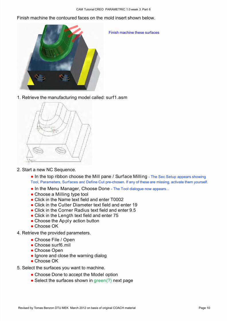
Machine the curved surface on the aircraft frame support shown below using AlongCutLine machining.
1. Open the manufacturing model: surf4.asm.
8/10/2019 UGE_3.pdf
http://slidepdf.com/reader/full/uge3pdf 8/21
CAM Tutorial CREO PARAMETRIC 1.0 week 3 Part 6
Revised by Tomas Benzon DTU MEK March 2012 on basis of original COACH material Page 8
The selection order is
unimportant...
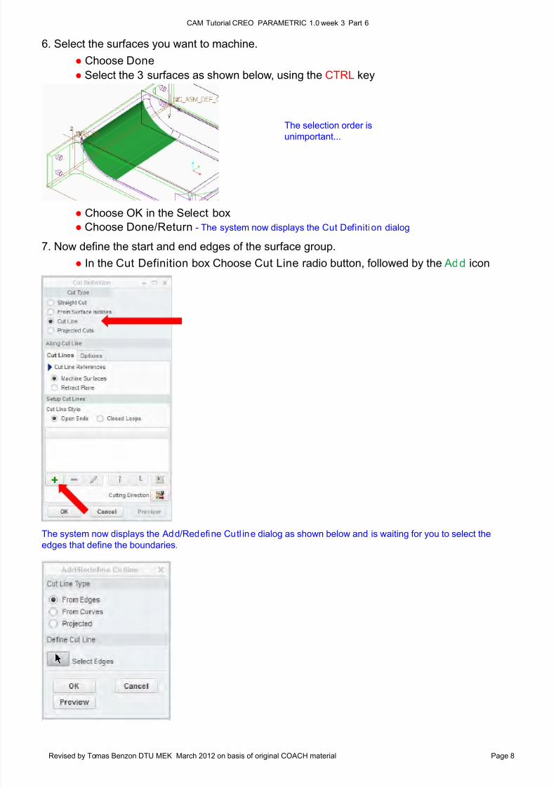
6. Select the surfaces you want to machine.
● Choose Done
● Select the 3 surfaces as shown below, using the CTRL key
● Choose OK in the Select box
● Choose Done/Return - The system now displays the Cut Definition dialog
The system now displays the Add/Redefine Cutl ine dialog as shown below and is waiting for you to select the
edges that define the boundaries.
7. Now define the start and end edges of the surface group.
● In the Cut Definition box Choose Cut Line radio button, followed by the Add icon
8/10/2019 UGE_3.pdf
http://slidepdf.com/reader/full/uge3pdf 9/21
CAM Tutorial CREO PARAMETRIC 1.0 week 3 Part 6
Revised by Tomas Benzon DTU MEK March 2012 on basis of original COACH material Page 9
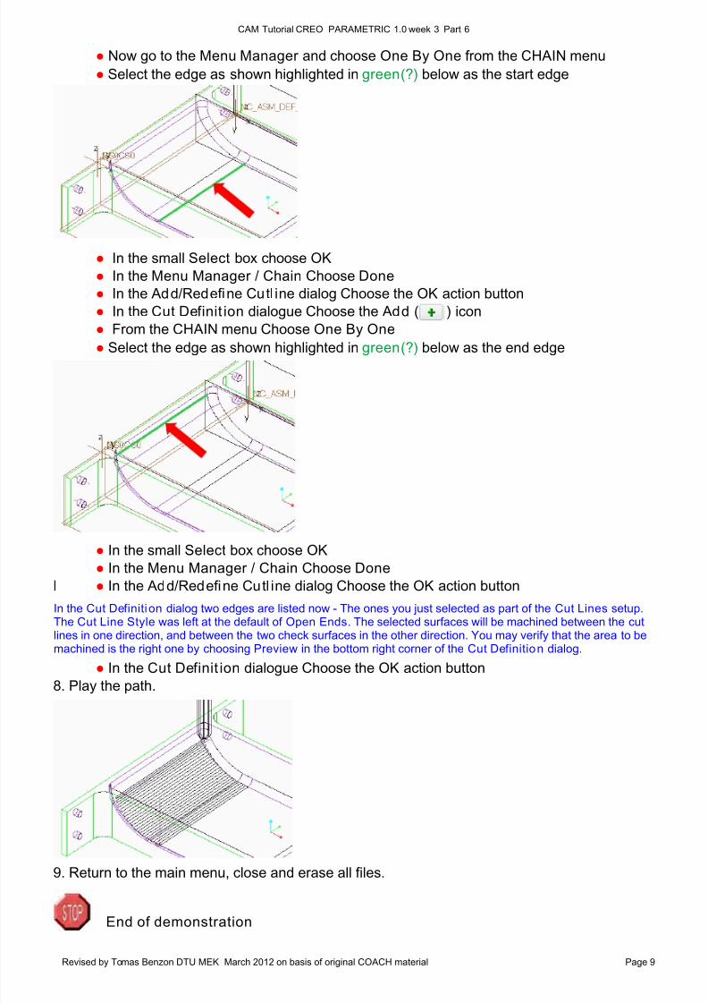
In the Cut Definition dialog two edges are listed now - The ones you just selected as part of the Cut Lines setup.The Cut Line Style was left at the default of Open Ends. The selected surfaces will be machined between the cutlines in one direction, and between the two check surfaces in the other direction. You may verify that the area to bemachined is the right one by choosing Preview in the bottom right corner of the Cut Definition dialog.
End of demonstration
● Now go to the Menu Manager and choose One By One from the CHAIN menu
● Select the edge as shown highlighted in green(?) below as the start edge
● In the small Select box choose OK
● In the Menu Manager / Chain Choose Done
● In the Add/Redefine Cutl ine dialog Choose the OK action button
● In the Cut Definit ion dialogue Choose the Add ( ) icon
● From the CHAIN menu Choose One By One
●
Select the edge as shown highlighted in green(?) below as the end edge
● In the small Select box choose OK
● In the Menu Manager / Chain Choose Done
I ● In the Add/Redefine Cutl ine dialog Choose the OK action button
● In the Cut Definit ion dialogue Choose the OK action button
8. Play the path.
9. Return to the main menu, close and erase all files.
8/10/2019 UGE_3.pdf
http://slidepdf.com/reader/full/uge3pdf 10/21
8/10/2019 UGE_3.pdf
http://slidepdf.com/reader/full/uge3pdf 11/21
CAM Tutorial CREO PARAMETRIC 1.0 week 3 Part 6
Revised by Tomas Benzon DTU MEK March 2012 on basis of original COACH material Page 11
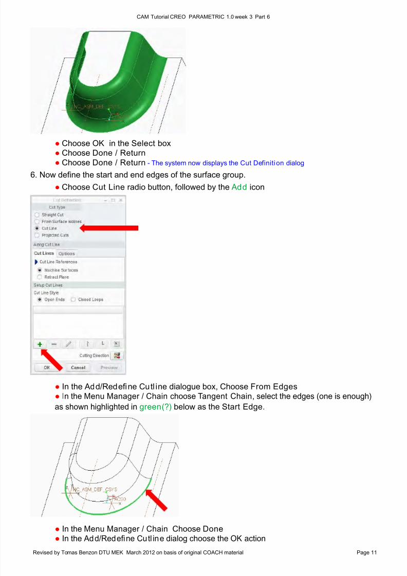
● Choose OK in the Select box ● Choose Done / Return
● Choose Done / Return - The system now displays the Cut Definition dialog
6. Now define the start and end edges of the surface group.
● Choose Cut Line radio button, followed by the Add icon
● In the Add/Redefine Cutl ine dialogue box, Choose From Edges● In the Menu Manager / Chain choose Tangent Chain, select the edges (one is enough)
as shown highlighted in green(?) below as the Start Edge.
● In the Menu Manager / Chain Choose Done ● In the Add/Redefine Cutl ine dialog choose the OK action
8/10/2019 UGE_3.pdf
http://slidepdf.com/reader/full/uge3pdf 12/21
CAM Tutorial CREO PARAMETRIC 1.0 week 3 Part 6
Revised by Tomas Benzon DTU MEK March 2012 on basis of original COACH material Page 12
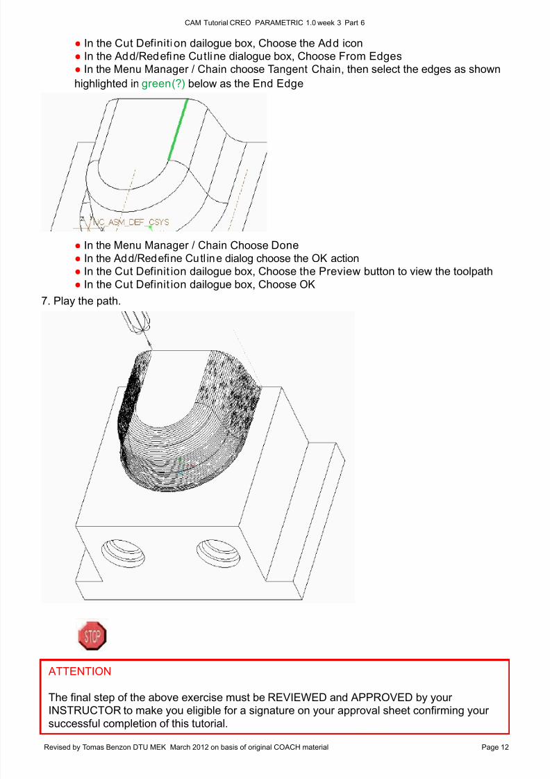
● In the Cut Definition dailogue box, Choose the Add icon ● In the Add/Redefine Cutline dialogue box, Choose From Edges ● In the Menu Manager / Chain choose Tangent Chain, then select the edges as shown
highlighted in green(?) below as the End Edge
● In the Menu Manager / Chain Choose Done
● In the Add/Redefine Cutl ine dialog choose the OK action
● In the Cut Definit ion dailogue box, Choose the Preview button to view the toolpath ● In the Cut Definit ion dailogue box, Choose OK
7. Play the path.
ATTENTION
The final step of the above exercise must be REVIEWED and APPROVED by yourINSTRUCTOR to make you eligible for a signature on your approval sheet confirming your
successful completion of this tutorial.
8/10/2019 UGE_3.pdf
http://slidepdf.com/reader/full/uge3pdf 13/21
CAM Tutorial CREO PARAMETRIC 1.0 week 3 Part 6
Revised by Tomas Benzon DTU MEK March 2012 on basis of original COACH material Page 13
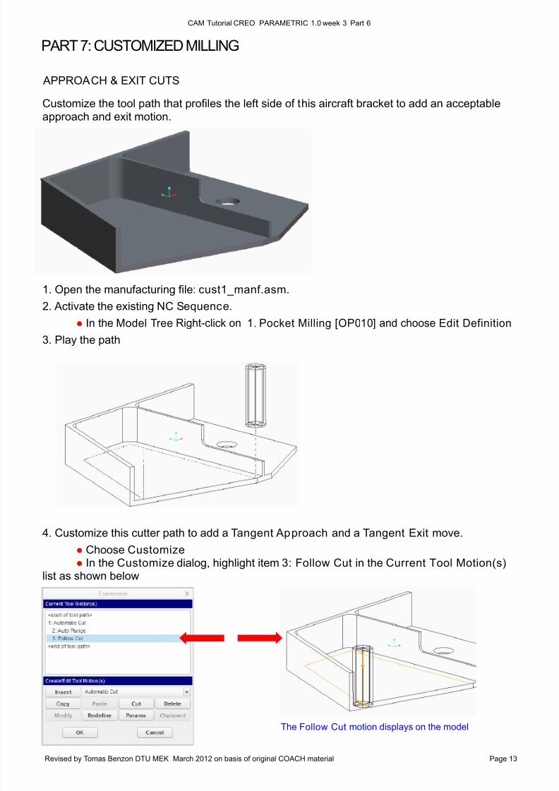
PART 7: CUSTOMIZED MILLING
APPROACH & EXIT CUTS
The Follow Cut motion displays on the model
Customize the tool path that profiles the left side of this aircraft bracket to add an acceptableapproach and exit motion.
1. Open the manufacturing file: cust1_manf.asm.
2. Activate the existing NC Sequence.
● In the Model Tree Right-click on 1. Pocket Milling [OP010] and choose Edit Definition
3. Play the path
4. Customize this cutter path to add a Tangent Approach and a Tangent Exit move.
●
Choose Customize ● In the Customize dialog, highlight item 3: Follow Cut in the Current Tool Motion(s) list as shown below
8/10/2019 UGE_3.pdf
http://slidepdf.com/reader/full/uge3pdf 14/21
CAM Tutorial CREO PARAMETRIC 1.0 week 3 Part 6
Revised by Tomas Benzon DTU MEK March 2012 on basis of original COACH material Page 14
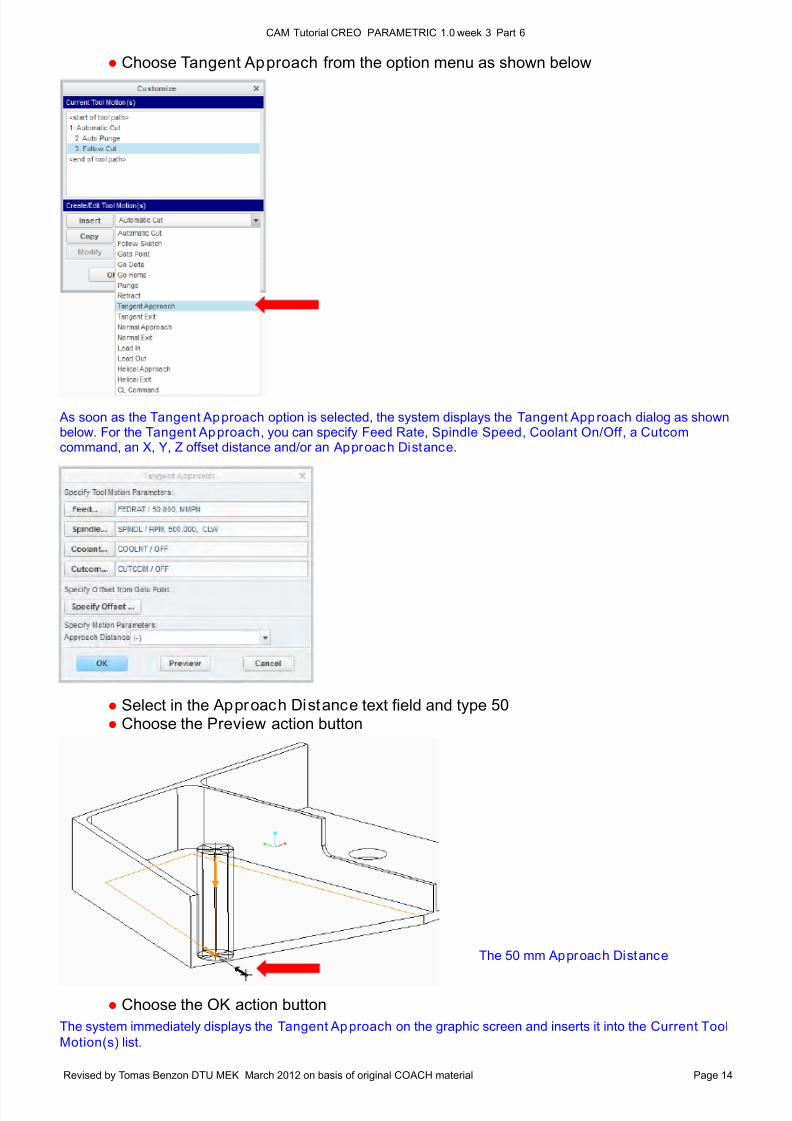
The 50 mm Approach Distance
The system immediately displays the Tangent Approach on the graphic screen and inserts it into the Current Tool
Motion(s) list.
As soon as the Tangent Approach option is selected, the system displays the Tangent Approach dialog as shownbelow. For the Tangent Approach, you can specify Feed Rate, Spindle Speed, Coolant On/Off , a Cutcomcommand, an X, Y, Z offset distance and/or an Approach Distance.
● Choose Tangent Approach from the option menu as shown below
● Select in the Approach Distance text field and type 50 ● Choose the Preview action button
● Choose the OK action button
8/10/2019 UGE_3.pdf
http://slidepdf.com/reader/full/uge3pdf 15/21
CAM Tutorial CREO PARAMETRIC 1.0 week 3 Part 6
Revised by Tomas Benzon DTU MEK March 2012 on basis of original COACH material Page 15
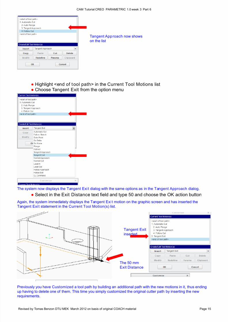
The 50 mm
Exit Distance
Tangent Approach now shows
on the list
Tangent Exit
inserted
The system now displays the Tangent Exi t dialog with the same options as in the Tangent Approach dialog.
Again, the system immediately displays the Tangent Exi t motion on the graphic screen and has inserted the
Tangent Exi t statement in the Current Tool Motion(s) list.
Previously you have Customized a tool path by building an additional path with the new motions in it, thus ending
up having to delete one of them. This time you simply customized the original cutter path by inserting the new
requirements.
● Highlight <end of tool path> in the Current Tool Motions list ● Choose Tangent Exit from the option menu
● Select in the Exit Distance text field and type 50 and choose the OK action button
8/10/2019 UGE_3.pdf
http://slidepdf.com/reader/full/uge3pdf 16/21
CAM Tutorial CREO PARAMETRIC 1.0 week 3 Part 6
Revised by Tomas Benzon DTU MEK March 2012 on basis of original COACH material Page 16
POSTPROCESSOR COMMANDS
Slow the Feed Rate to 15.0
MMPM along this thin Rib
You want the block of text to go as close to the front of the file as possible. You will also notice that the only param-
eter you can enter is a CL Command. A CL Command is the only option that can be inserted at the beginning of a
cutter file.
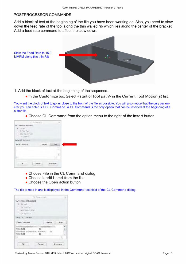
The file is read in and is displayed in the Command text field of the CL Command dialog.
Add a block of text at the beginning of the file you have been working on. Also, you need to slowdown the feed rate of the tool along the thin walled rib which lies along the center of the bracket. Add a feed rate command to affect the slow down.
1. Add the block of text at the beginning of the sequence. ● In the Customize box Select <start of tool path> in the Current Tool Motion(s) list.
● Choose CL Command from the option menu to the right of the Insert button
● Choose File in the CL Command dialog● Choose loadtl1.cmd from the list● Choose the Open action button
8/10/2019 UGE_3.pdf
http://slidepdf.com/reader/full/uge3pdf 17/21
CAM Tutorial CREO PARAMETRIC 1.0 week 3 Part 6
Revised by Tomas Benzon DTU MEK March 2012 on basis of original COACH material Page 17
One line of text from the file is shown in the Current Tool Motion(s) listing, but to see the complete text just look at
the CL Data window, which now appears as a result of the Open command. The CL Data window is only for
viewing and it responds when you highlight one of the Tool Motions in the Customize box.
Please notice that the CL Data window may hide behind the whole Creo screen. (use ALT - TAB to display it)
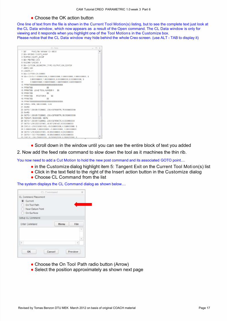
You now need to add a Cut Motion to hold the new post command and its associated GOTO point....
The system displays the CL Command dialog as shown below....
● Choose the OK action button
● Scroll down in the window until you can see the entire block of text you added
2. Now add the feed rate command to slow down the tool as it machines the thin rib.
●
in the Customize dialog highlight item 5: Tangent Exit on the Current Tool Motion(s) list ● Click in the text field to the right of the Insert action button in the Customize dialog ● Choose CL Command from the list
● Choose the On Tool Path radio button (Arrow) ● Select the position approximately as shown next page
8/10/2019 UGE_3.pdf
http://slidepdf.com/reader/full/uge3pdf 18/21
CAM Tutorial CREO PARAMETRIC 1.0 week 3 Part 6
Revised by Tomas Benzon DTU MEK March 2012 on basis of original COACH material Page 18
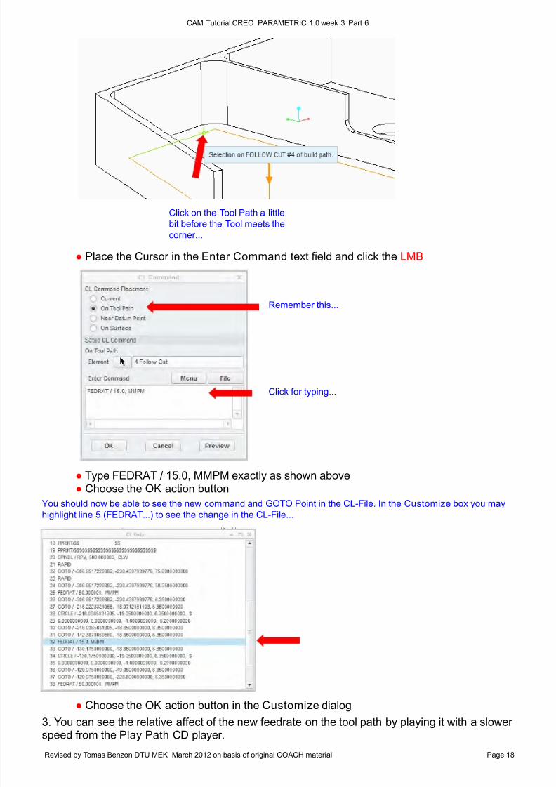
Click on the Tool Path a little
bit before the Tool meets the
corner...
Remember this...
Click for typing...
You should now be able to see the new command and GOTO Point in the CL-File. In the Customize box you may
highlight line 5 (FEDRAT...) to see the change in the CL-File...
● Place the Cursor in the Enter Command text field and click the LMB
● Type FEDRAT / 15.0, MMPM exactly as shown above ● Choose the OK action button
● Choose the OK action button in the Customize dialog
3. You can see the relative affect of the new feedrate on the tool path by playing it with a slowerspeed from the Play Path CD player.
8/10/2019 UGE_3.pdf
http://slidepdf.com/reader/full/uge3pdf 19/21
CAM Tutorial CREO PARAMETRIC 1.0 week 3 Part 6
Revised by Tomas Benzon DTU MEK March 2012 on basis of original COACH material Page 19
Notice how the tool changes speeds depending on the commands that you just added...
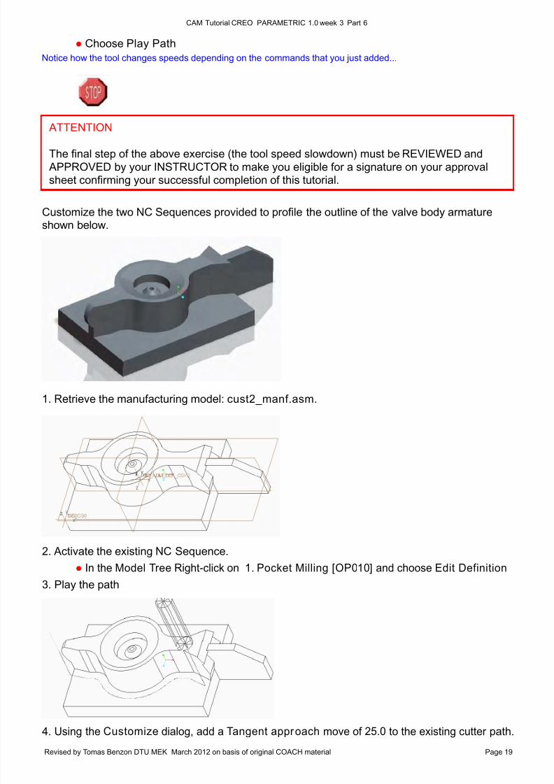
2. Activate the existing NC Sequence.
● In the Model Tree Right-click on 1. Pocket Milling [OP010] and choose Edit Definition
3. Play the path
● Choose Play Path
Customize the two NC Sequences provided to profile the outline of the valve body armatureshown below.
1. Retrieve the manufacturing model: cust2_manf.asm.
4. Using the Customize dialog, add a Tangent approach move of 25.0 to the existing cutter path.
ATTENTION
The final step of the above exercise (the tool speed slowdown) must be REVIEWED and
APPROVED by your INSTRUCTOR to make you eligible for a signature on your approvalsheet confirming your successful completion of this tutorial.
8/10/2019 UGE_3.pdf
http://slidepdf.com/reader/full/uge3pdf 20/21
CAM Tutorial CREO PARAMETRIC 1.0 week 3 Part 6
Revised by Tomas Benzon DTU MEK March 2012 on basis of original COACH material Page 20
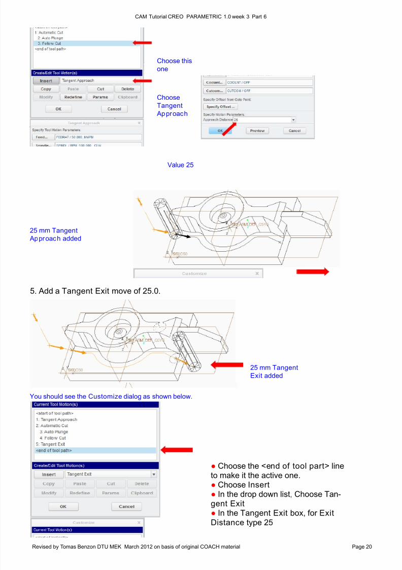
25 mm Tangent
Approach added
ChooseTangent
Approach
Choose this
one
Value 25
25 mm Tangent
Exit added
You should see the Customize dialog as shown below.
● Choose the <end of tool part> lineto make it the active one.● Choose Insert● In the drop down list, Choose Tan-gent Exit● In the Tangent Exit box, for ExitDistance type 25
5. Add a Tangent Exit move of 25.0.
8/10/2019 UGE_3.pdf
http://slidepdf.com/reader/full/uge3pdf 21/21
CAM Tutorial CREO PARAMETRIC 1.0 week 3 Part 6
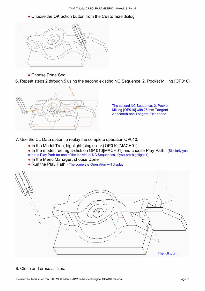
The second NC Sequence: 2. Pocket
Milling [OP010] with 25 mm Tangent
Approach and Tangent Exit added
● Choose the OK action button from the Customize dialog
● Choose Done Seq
6. Repeat steps 2 through 5 using the second existing NC Sequence: 2. Pocket Milling [OP010]
7. Use the CL Data option to replay the complete operation OP010.
● In the Model Tree, highlight (singleclick) OP010 [MACH01] ● In the model tree, right-click on OP 010[MACH01] and choose Play Path - (Similarly you
can run Play Path for one of the individual NC Sequences, if you pre-highlight it)
● In the Menu Manager , choose Done ● Run the Play Path - The complete Operation will display
8. Close and erase all files.
The full tour...
![H20youryou[2] · 2020. 9. 1. · 65 pdf pdf xml xsd jpgis pdf ( ) pdf ( ) txt pdf jmp2.0 pdf xml xsd jpgis pdf ( ) pdf pdf ( ) pdf ( ) txt pdf pdf jmp2.0 jmp2.0 pdf xml xsd](https://img.pdfslide.tips/doc/110x75/60af39aebf2201127e590ef7/h20youryou2-2020-9-1-65-pdf-pdf-xml-xsd-jpgis-pdf-pdf-txt-pdf-jmp20.jpg)