Embed Size (px)
Citation preview
UN-R100-02-S03 (2016.6.18)
Regulation No. 100 協定規則第 100 号
Uniform provisions concerning the approval of vehicles with regard to specific
requirements for the electric power train
電動パワートレーンの特定要件に係る車両の認可に関する統一規定
Contents 目次
Regulation
1. Scope
2. Definitions
3. Application for approval
4. Approval
5. Part I: Requirements of a vehicle with regard to its electrical safety
6. Part II: Requirements of a Rechargeable Electrical Energy Storage System
(REESS) with regard to its safety
規則
1. 適用範囲
2. 定義
3. 認可申請
4. 認可
5. 第 I 部:電気安全に係る車両の要件
6. 第 II 部:安全に係る充電式電気エネルギー貯蔵システム(REESS)の要
件
7. Modifications and extension of the type approval
8. Conformity of production
9. Penalties for non-conformity of production
10. Production definitively discontinued
7. 型式認可の変更及び拡大
8. 生産の適合性
9. 生産の不適合に対する罰則
10. 生産中止
11. Names and addresses of Technical Services responsible for conducting approval
tests and of Type Approval Authorities
11. 認可試験を担当する技術機関及び行政官庁の名称及び所在地
12. Transitional provisions 12. 過渡規定
Annexes
1 Part 1 - Communication concerning the approval or extension or refusal or
withdrawal of approval or production definitively discontinued of a vehicle type
with regard to its electrical safety pursuant to Regulation No. 100
附則
附則 1 第 1部 − 協定規則第 100号に準拠した電気安全に係る車両型式の認
可付与、認可拡大、認可拒否、認可取消又は生産中止関する通知
1 Part 2 - Communication concerning the approval or extension or refusal or
withdrawal of approval or production definitively discontinued of a REESS type as
component/separate technical unit pursuant to Regulation No. 100
2 Arrangements of the approval marks
3 Protection against direct contacts of parts under voltage
4A Isolation resistance measurement method for vehicle based tests
4B Isolation resistance measurement method for component based tests of a REESS
5 Confirmation method for function of on-board isolation resistance monitoring
system
附則 1 第 2部 − 協定規則第 100号に準拠する構成部品/単体技術ユニット
としての REESS 型式の認可付与、認可拡大、認可拒否、認可取消又は生産
中止に関する通知
附則 2 認可マークの配置
附則 3 電圧が印加された部位の直接接触に対する保護
附則 4A 車両に基づく試験に関する絶縁抵抗測定方法
附則 4B REESS の構成部品に基づく試験に関する絶縁抵抗測定方法
附則 5 車載絶縁抵抗監視システムの機能に関する確認方法
6 Part 1 - Essential characteristics of road vehicles or systems
6 Part 2 - Essential characteristics of REESS
6 Part 3: Essential characteristics of road vehicles or systems with chassis
connected to electrical circuits
7 Determination of hydrogen emissions during the charge procedures of the REESS
Appendix 1 - Calibration of equipment for hydrogen emission testing
Appendix 2 - Essential characteristics of the vehicle family
8 REESS test procedures
Appendix 1 - Procedure for conducting a standard cycle
8A Vibration test
8B Thermal shock and cycling test
8C Mechanical shock
8D Mechanical integrity
8E Fire resistance
Appendix 1 - Dimension and technical data of firebricks
附則 6 第 1 部 − 道路車両又はシステムの基本特性
附則 6 第 2 部 − REESS の基本特性
附則6 第3部 − 電気回路接続シャシを備えた道路車両またはシステムの本
質的な特性
附則 7 REESS の充電手順における水素エミッションの測定
付録 1 − 水素エミッション試験用装置のキャリブレーション
付録 2 − 車両ファミリーの基本特性
附則 8 REESS 試験手順
付録 1 − 標準サイクルを実施する手順
附則 8A 振動試験
附則 8B 熱衝撃及びサイクル試験
附則 8C メカニカルショック
附則 8D メカニカルインテグリティ
附則 8E 耐火性
付録 1 − 耐火れんがの寸法及び技術データ
8F External short circuit protection
8G Overcharge protection
8H Over-discharge protection
8I Over-temperature protection
附則 8F 外部短絡保護
附則 8G 過充電保護
附則 8H 過放電保護
附則 8I 過昇温保護
1. Scope
1.1. Part I: Safety requirements with respect to the electric power train of road
vehicles of categories M and N1, with a maximum design speed exceeding 25 km/h,
equipped with one or more traction motor(s) operated by electric power and not
permanently connected to the grid, as well as their high voltage components and
systems which are galvanically connected to the high voltage bus of the electric
power train.
1 As defined in the Consolidated Resolution on the Construction of Vehicles
(R.E.3.), document ECE/TRANS/WP.29/78/Rev.2, para. 2.
Part I of this regulation does not cover post-crash safety requirements of road
vehicles.
1. 適用範囲
1.1. 第 I 部:最高設計速度が 25 km/h を超える区分 M 及び N 1の道路車両で、
電力で作動し、送電線に恒久的に接続されていない駆動用モーターを 1 つ以
上装備した車両の電動パワートレーン、並びに電動パワートレーンの高電圧
回路に直流電気的に接続されたその高電圧構成部品及びシステムに係る安
全要件。
1 車両構造統合決議(R.E.3)の文書 ECE/TRANS/WP.29/78/Rev.2, para.2.の定
義による。
本規則の第 I 部には、道路車両の衝突後の安全要件は含まれない。
1.2. Part II: Safety requirements with respect to the Rechargeable Electrical
Energy Storage System (REESS), of road vehicles of categories M and N
equipped with one or more traction motors operated by electric power and not
permanently connected to the grid.
Part II of this Regulation does not apply to REESS(s) whose primary use is to
supply power for starting the engine and/or lighting and/or other vehicle auxiliaries
systems.
1.2. 第 II 部:電力で作動し、恒久的に送電線に接続されていない駆動用モ
ーターを 1 つ以上装備した区分 M 及び N の道路車両の充電式電気エネルギ
ー貯蔵システム(REESS)に係る安全要件。
本規則の第 II 部は、主な用途がエンジンの始動又は照明又はその他の車両
補助システムに電力を供給することである REESS に適用しない。
2. Definitions 2. 定義
For the purpose of this Regulation the following definitions apply:
2.1. "Active driving possible mode" means the vehicle mode when application of
pressure to the accelerator pedal (or activation of an equivalent control) or release of
the brake system will cause the electric power train to move the vehicle.
本規則の目的のために、以下の定義が適用される。
2.1. 「自走可能状態」とは、アクセルペダルの踏み込み(又は同等のコント
ロール装置の作動)又はブレーキシステムの解除により電動パワートレーン
が車両を動かす時の車両状態をいう。
2.2. "Barrier" means the part providing protection against direct contact to the live
parts from any direction of access.
2.3. "Cell" means a single encased electrochemical unit containing one positive and
one negative electrode which exhibits a voltage differential across its two terminals.
2.4. "Conductive connection" means the connection using connectors to an external
power supply when the Rechargeable Electrical Energy storage system (REESS)
is charged.
2.2. 「バリヤ」とは、あらゆる接近方向からの活電部への直接接触に対する
保護のために設けられた部分をいう。
2.3. 「電池」とは、ケースに入った、正極が 1 つと負極が 1 つある単体の電
気化学的ユニットで、その 2 つの端子間で電圧差があるものをいう。
2.4. 「コンダクティブ接続」とは、充電式電気エネルギー貯蔵システム
(REESS)の充電時におけるコネクタを用いた外部電源への接続をいう。
2.5. "Coupling system for charging the Rechargeable Electrical Energy Storage
System (REESS)" means the electrical circuit used for charging the REESS from an
external electric power supply including the vehicle inlet.
2.6. "C Rate" of "n C" is defined as the constant current of the tested-device, which
takes 1/n hours to charge or discharge the tested-device between 0 per cent of the
state of charge and 100 per cent of the state of charge.
2.5. 「充電式電気エネルギー貯蔵システム(REESS)充電用連結システム」
とは、外部電源から REESS を充電するために使用される電気回路(車両イ
ンレットを含む)をいう。
2.6. 「n C」の「C 率」は、0%の充電状態から 100%の充電状態まで充電、
又は 100%の充電状態から 0%の充電状態まで放電するのに 1/n 時間かかる
試験対象装置の定電流のことをいう。
2.7. "Direct contact" means the contact of persons with live parts.
2.8. "Electrical chassis" means a set made of conductive parts electrically linked
together, whose potential is taken as reference.
2.9. "Electrical circuit" means an assembly of connected live parts which is
designed to be electrically energized in normal operation.
2.7. 「直接接触」とは、人が活電部に接触することをいう。
2.8. 「電気的シャシ」とは、電気的に互いに接続された導電性の部分の集合
体であって、その電位が基準とみなされるものをいう。
2.9. 「電気回路」とは、通常の作動時に電流が流れるように設計された活電
部を接続したものの集合体をいう。
2.10. "Electric energy conversion system" means a system that generates and
provides electric energy for electric propulsion.
2.11. "Electric power train" means the electrical circuit which includes the traction
2.10. 「電気エネルギー変換システム」とは、電気的駆動力のために電気エ
ネルギーを発生し、これを提供するシステムをいう。
2.11. 「電動パワートレーン」とは、駆動用モーターを含む電気回路をいい、
motor(s), and may include the REESS, the electric energy conversion system, the
electronic converters, the associated wiring harness and connectors, and the
coupling system for charging the REESS.
REESS、電気エネルギー変換システム、電子式コンバーター、付随する配線
ハーネス及びコネクタ、並びに REESS 充電用連結システムを含む場合があ
る。
2.12. "Electronic converter" means a device capable of controlling and/or
converting electric power for electric propulsion.
2.13. "Enclosure" means the part enclosing the internal units and providing
protection against direct contact from any direction of access.
2.14. "Exposed conductive part" means the conductive part which can be touched
under the provisions of the protection IPXXB, and which becomes electrically
energized under isolation failure conditions. This includes parts under a cover that
can be removed without using tools.
2.12. 「電子式コンバーター」とは、電気的駆動力のために電力を制御又は
変換できる装置をいう。
2.13. 「エンクロージャ」とは、あらゆる接近方向からの直接接触に対して、
内部の機器を包み込み保護するために設けられた部分をいう。
2.14. 「露出導電部」とは、保護 IPXXB の措置を施した状態で触れることが
でき、絶縁故障状態で通電される導電部をいう。これは、工具を使用せずに
除去できるカバーで覆われている部品も含む。
2.15. "Explosion" means the sudden release of energy sufficient to cause pressure
waves and/or projectiles that may cause structural and/or physical damage to the
surrounding of the tested-device.
2.15. 「爆発」とは、試験対象装置の周辺に構造的又は物理的損傷を生じさ
せる可能性のある圧力波又は投射物を発生させるのに十分なエネルギーの
突然の放出をいう。
2.16. "External electric power supply" means an alternating current (AC) or direct
current (DC) electric power supply outside of the vehicle.
2.16. 「外部電源」とは、車両外部の交流(AC)又は直流(DC)電源をい
う。
2.17. "High Voltage" means the classification of an electric component or circuit, if
its working voltage is > 60 V and < 1500 V DC or > 30 V and < 1000 V AC root
mean square (rms).
2.17. 「高電圧」とは、作動電圧が>60 V かつ≦1,500 V DC 又は>30 V か
つ≦1,000 V AC(実効値(rms))である場合の電気部品又は回路の分類を
いう。
2.18. "Fire" means the emission of flames from a tested-device. Sparks and arcing
shall not be considered as flames.
2.18. 「火炎」とは、試験対象装置からの炎の放出をいう。スパーク及びア
ーク放電は炎とはみなさないものとする。
2.19. "Flammable electrolyte" means an electrolyte that contains substances
classified as Class 3 "flammable liquid" under "UN Recommendations on the
Transport of Dangerous Goods - Model Regulations (Revision 17 from June 2011),
Volume I, Chapter 2.3"2
2.19. 「可燃性電解液」とは、「危険物輸送に関する UN 勧告−モデル規則(2011
年 6 月から改訂 17)、I 巻、2.3 章」のクラス 3「可燃性液体」に分類され
る物質を含む電解液をいう。2
2 www.unece.org/trans/danger/publi/unrec/rev17/17files_e.html
2 www.unece.org/trans/danger/publi/unrec/rev17/17files_e.html
2.20. "High voltage bus" means the electrical circuit, including the coupling system
for charging the REESS that operates on high voltage.
Where electrical circuits, that are galvanically connected to each other, are
galvanically connected to the electrical chassis and the maximum voltage between
any live part and the electrical chassis or any exposed conductive part is 30 V AC
and 60 V DC, only the components or parts of the electric circuit that operate on
high voltage are classified as a high voltage bus.
2.21. "Indirect contact" means the contact of persons with exposed conductive parts.
2.22. "Live parts" means the conductive part(s) intended to be electrically energized
in normal use.
2.20. 「高電圧バス」とは、高電圧で作動する REESS 充電用連結システムを
含む電気回路を指す。
互いに直流電気的に接続された電気回路が電気的シャシに直流電気的に接
続されており、活電部と電気的シャシまたは露出導電部の間の最大電圧が≦
30 V AC かつ≦60 V DC である場合は、当該電気回路の高電圧で作動する構
成部品または部位のみを高電圧バスとして分類する。
2.21. 「間接接触」とは、人が露出導電部に接触することをいう。
2.22. 「活電部」とは、通常の使用時に通電することを目的とした導電部を
いう。
2.23. "Luggage compartment" means the space in the vehicle for luggage
accommodation, bounded by the roof, hood, floor, side walls, as well as by the
barrier and enclosure provided for protecting the occupants from direct contact with
live parts, being separated from the passenger compartment by the front bulkhead or
the rear bulk head.
2.23. 「荷物室」とは、荷物を収容する車両内部のスペースで、ルーフ、フ
ード、フロア、側壁、並びに活電部との直接接触から乗員を保護するために
設けられたバリヤ及びエンクロージャを境界とし、前部隔壁又は後部隔壁に
より客室と区分された部分をいう。
2.24. "Manufacturer" means the person or body who is responsible to the approval
authority for all aspects of the type approval process and for ensuring conformity of
production. It is not essential that the person or body be directly involved in all
stages of the construction of the vehicle, system or component which is the subject
of the approval process.
2.24. 「メーカー」とは、型式認可プロセスのすべての面について、及び生
産の適合性を保証することについて認可当局に対して責任を有する者又は
団体をいう。当該者又は団体が、認可プロセスの対象となる車両、システム
又は構成部品の製造のすべての段階に直接関与することは不可欠ではない。
2.25. "On-board isolation resistance monitoring system" means the device which
monitors the isolation resistance between the high voltage buses and the electrical
chassis.
2.25. 「車載絶縁抵抗監視システム」とは、高電圧回路と電気的シャシの間
の絶縁抵抗を監視する装置をいう。
2.26. "Open type traction battery" means a liquid type battery requiring refilling 2.26. 「開放式駆動用バッテリー」とは、補水を必要とし、大気に放出され
with water and generating hydrogen gas released to the atmosphere. る水素ガスを発生する液式のバッテリーをいう。
2.27. "Passenger compartment" means the space for occupant accommodation,
bounded by the roof, floor, side walls, doors, window glass, front bulkhead and rear
bulkhead, or rear gate, as well as by the barriers and enclosures provided for
protecting the occupants from direct contact with live parts.
2.27. 「客室」とは、乗員を収容するスペースで、ルーフ、フロア、側壁、
扉、窓ガラス、前部隔壁及び後部隔壁、又はリアゲート、並びに活電部との
直接接触から乗員を保護するために設けられたバリヤ及びエンクロージャ
を境界とする部分をいう。
2.28. "Protection degree" means the protection provided by a barrier/enclosure
related to the contact with live parts by a test probe, such as a test finger (IPXXB) or
a test wire (IPXXD), as defined in Annex 3.
2.28. 「保護等級」とは、附則 3 に定義された近接プローブ(IPXXB)又は
試験ワイヤ(IPXXD)などの試験プローブを使った活電部への接触に関連
するバリヤ/エンクロージャによる保護をいう。
2.29. "Rechargeable Electrical Energy Storage System (REESS)" means the
Rechargeable Electrical Energy storage system that provides electric energy for
electric propulsion.
The REESS may include subsystem(s) together with the necessary ancillary systems
for physical support, thermal management, electronic control and enclosures.
2.29. 「充電式電気エネルギー貯蔵システム(REESS)」とは、電気的推進
のために電気エネルギーを提供する充電式電気エネルギー貯蔵システムを
いう。
REESS は、物理的サポート、熱管理、電子制御及びエンクロージャ用の必
要な補助システムを装備したサブシステムを含む場合がある。
2.30. "Rupture" means opening(s) through the casing of any functional cell
assembly created or enlarged by an event, large enough for a 12 mm diameter test
finger (IPXXB) to penetrate and make contact with live parts (see Annex 3).
2.30. 「破裂」とは、ある事象によってできた、又は拡大した機能電池アッ
センブリのケーシングの開口部で、直径 12 mm の近接プローブ(IPXXB)
が貫通して活電部と接触するだけ十分な大きさのものをいう(附則 3 参照の
こと)。
2.31. "Service disconnect" means the device for deactivation of the electrical circuit
when conducting checks and services of the REESS, fuel cell stack, etc.
2.31. 「サービスディスコネクト」とは、REESS、燃料電池スタックなどの
点検及び整備を行う時に電気回路を不作動にするための装置をいう。
2.32. "State of Charge (SOC)" means the available electrical charge in a
tested-device expressed as a percentage of its rated capacity.
2.33. "Solid insulator" means the insulating coating of wiring harnesses provided in
order to cover and protect the live parts against direct contact from any direction of
access; covers for insulating the live parts of connectors, and varnish or paint for the
purpose of insulation.
2.32. 「充電状態(SOC)」とは、試験対象装置内で使用可能な電荷をその
定格容量のパーセンテージとして表示したものをいう。
2.33. 「固体の絶縁体」とは、あらゆる接近方向からの直接接触に対して活
電部を覆い保護するために設けられた配線ハーネスの絶縁被覆、コネクタの
活電部を絶縁するためのカバー、並びに絶縁を目的としたワニス又は塗料を
いう。
2.34. "Subsystem" means any functional assembly of REESS components.
2.35. "Tested-device" means either the complete REESS or the subsystem of a
REESS that is subjected to the tests prescribed by this Regulation.
2.34. 「サブシステム」とは、REESS 構成部品の機能アッセンブリをいう。
2.35. 「試験対象装置」とは、本規則で定める試験の対象となる完全 REESS
又は REESS のサブシステムのいずれかをいう。
2.36. "Type of REESS" means systems which do not differ significantly in such
essential aspects as:
(a) The manufacturer's trade name or mark;
(b) The chemistry, capacity and physical dimensions of its cells;
(c) The number of cells, the mode of connection of the cells and the physical
support of the cells;
(d) The construction, materials and physical dimensions of the casing and
(e) The necessary ancillary devices for physical support, thermal management and
electronic control.
2.36. 「REESS 型式」とは、以下の基本的な特徴において大きな差異がない
システムをいう。
(a) メーカーの商号又は商標、
(b) その電池の化学的性質、容量及び物理的寸法、
(c) 電池の数、電池の接続モード及び電池の物理的サポート、
(d) ケーシングの構造、材質及び物理的寸法並びに
(e) 物理的サポート、熱管理及び電子制御用に必要な補助装置。
2.37. "Vehicle type" means vehicles which do not differ in such essential aspects as:
(a) Installation of the electric power train and the galvanically connected high
voltage bus;
(b) Nature and type of electric power train and the galvanically connected high
voltage components.
2.37. 「車両型式」とは、以下の基本的な特徴において差異のない車両をい
う。
(a) 電動パワートレーン及び直流電気的に接続されている高電圧回路の搭
載。
(b) 電動パワートレーン及び直流電気的に接続されている高電圧構成部品
の特性及び型式。
2.38. "Working voltage" means the highest value of an electrical circuit voltage
root-mean-square (rms), specified by the manufacturer, which may occur between
any conductive parts in open circuit conditions or under normal operating condition.
If the electrical circuit is divided by galvanic isolation, the working voltage is
defined for each divided circuit, respectively.
2.38. 「作動電圧」とは、開回路状態又は通常の作動状態において、あらゆ
る導電部の間に発生する可能性がある電気回路電圧の実効値(rms)の最高
値であり、メーカーが定めるものをいう。電気回路が直流電気的絶縁により
分割されている場合、作動電圧は、分割された各回路に対しそれぞれ定めら
れる。
2.39. "Chassis connected to the electric circuit" means AC and DC electric circuits
galvanically connected to the electrical chassis.
2.39. 「電気回路接続シャシ」とは、電気的シャシに直流電気的に接続され
た AC および DC の電気回路を指す。
3. Application for approval
3.1. Part I: Approval of a vehicle type with regard to its electrical safety, including
the High Voltage System
3. 認可申請
3.1. 第 I 部:高電圧システムを含む電気安全に係る車両型式の認可
3.1.1. The application for approval of a vehicle type with regard to specific
requirements for the electric power train shall be submitted by the vehicle
manufacturer or by his duly accredited representative.
3.1.1. 電動パワートレーンに関する特定要件に係る車両型式の認可申請は、
当該自動車メーカー又はその正規の委任代理人が行うものとする。
3.1.2. It shall be accompanied by the under-mentioned documents in triplicate and
following particulars:
3.1.2.1. Detailed description of the vehicle type as regards the electric power train
and the galvanically connected high voltage bus.
3.1.2. 申請書には、以下に掲げる項目の詳細を記載した書面を 3 部添付しな
ければならない。
3.1.2.1. 電動パワートレーン及び直流電気的に接続されている高電圧回路に
関する車両型式の詳細説明。
3.1.2.2. For vehicles with REESS, additional evidence showing that the REESS is in
compliance with the requirements of paragraph 6. of this Regulation.
3.1.3. A vehicle representative of the vehicle type to be approved shall be submitted
to the Technical Service responsible for conducting the approval tests and, if
applicable, at the manufacturer's discretion with the agreement of the Technical
Service, either additional vehicle(s), or those parts of the vehicle regarded by the
Technical Service as essential for the test(s) referred to in the paragraph 6. of this
Regulation.
3.1.2.2. REESS を装備した車両については、当該 REESS が本規則の 6 項の要
件に適合していることを示す付加的証拠。
3.1.3. 認可対象の車両型式を代表する車両 1 台、並びに該当する場合は、メ
ーカーの裁量により、技術機関の同意を得た上で、追加車両又は技術機関が
本規則の 6 項に言及される試験に不可欠であるとみなす車両部品のいずれ
かを、認可試験を実施する責任を有する技術機関に提出するものとする。
3.2. Part II: Approval of a Rechargeable Electrical Energy Storage System
(REESS)
3.2.1. The application for approval of a type of REESS or separate technical unit
with regard to the safety requirements of the REESS shall be submitted by the
REESS manufacturer or by his duly accredited representative.
3.2. 第 II 部:充電式電気エネルギー貯蔵システム(REESS)の認可
3.2.1. REESS の安全要件に係る REESS 又は単体技術ユニットの型式認可の
申請は、当該 REESS メーカー又はその正規の委任代理人が行うものとする。
3.2.2. It shall be accompanied by the under-mentioned documents in triplicate and 3.2.2. 申請書には、以下に掲げる項目の詳細を記載した書面を 3 部添付しな
comply with the following particulars:
3.2.2.1. Detailed description of the type of REESS or separate technical unit as
regards the safety of the REESS.
ければならない。
3.2.2.1. REESS の安全に係る REESS 又は単体技術ユニットの型式の詳細な
説明。
3.2.3. A component(s) representative of the type of REESS to be approved plus, at
the manufacturer's discretion, and with the agreement of the Technical Service,
those parts of the vehicle regarded by the Technical Service as essential for the test,
shall be submitted to the Technical Service responsible for conducting the approval
tests.
3.2.3. 認可対象の REESS 型式を代表する構成部品、並びにメーカーの裁量
により、技術機関の同意を得た上で、技術機関が試験に不可欠であるとみな
す車両部品を、認可試験の実施する責任を有する技術機関に提出するものと
する。
3.3. The Type Approval Authority shall verify the existence of satisfactory
arrangements for ensuring effective control of the conformity of production before
type approval is granted.
3.3. 型式の認可を行う行政官庁は、型式認可を付与する前に、生産の適合性
の有効な管理を確保するための十分な体制が存在することを確認するもの
とする。
4. Approval
4.1. If the type submitted for approval pursuant to this Regulation meets the
requirements of the relevant parts of this Regulation, approval of that type shall be
granted.
4. 認可
4.1. 本規則に従って認可のために提出される型式が、本規則の該当部分の要
件に適合した場合、当該型式の認可を付与するものとする。
4.2. An approval number shall be assigned to each type approved. Its first two digits
(at present 02 for the Regulation in its form) shall indicate the series of amendments
incorporating the most recent major technical amendments made to the Regulation
at the time of issue of the approval. The same Contracting Party shall not assign the
same number to another vehicle type.
4.2. 認可番号は、認可された型式毎に割り当てるものとする。認可番号の最
初の 2 桁(現在は本規則の版に対応する「02」)は、本規則に加えられた主
要な技術的修正に関して、認可を行う時点における最新の改訂版を示すもの
とする。同一締約国において、異なる車両型式に対して同一の番号を割り当
ててはならないものとする。
4.3. Notice of approval or of refusal or of extension or withdrawal of approval or
production definitively discontinued of a vehicle type pursuant to this Regulation
shall be communicated to the Parties to the Agreement applying this Regulation, by
means of a form conforming to the model in Annex 1, Part 1 or 2 as appropriate to
4.3. 本規則による車両型式の認可付与、認可拡大、認可拒否、認可取消又は
生産中止の通知は、本規則の附則 1 の第 1 部又は 2 の該当する方の様式によ
り、本規則を適用する他の協定締約国に対して行うものとする。
this Regulation.
4.4. There shall be affixed, conspicuously and in a readily accessible place specified
on the approval form, to every vehicle or REESS or separate technical unit
conforming to a type approved under this Regulation an international approval mark
consisting of:
4.4. 本規則に基づく認可を受けた型式に適合する全ての車両又は REESS 又
は単体技術ユニットには、下記から成る国際認可マークを、認可書に記載さ
れた容易に視認できる位置に表示するものとする。
4.4.1. A circle surrounding the letter "E" followed by the distinguishing number of
the country which has granted approval3.
3 The distinguishing numbers of the Contracting Parties to the 1958 Agreement are
reproduced in Annex 3 to Consolidated Resolution on the Construction of Vehicles
(R.E.3), document ECE/TRANS/WP.29/78/Rev.2/Amend.3
4.4.1. 文字「E」及びその後に認可を付与した国の識別番号を記載し、その
全体を円で囲む 3。
3 1958 年協定の締約国の識別番号は、車両構造統合決議(R.E.3)の附則 3、
文書 ECE/TRANS/WP.29/78/Rev.2/Amend.3 に再録されている。
4.4.2.
The number of this Regulation, followed by the letter "R", a dash and the approval
number to the right of the circle described in paragraph 4.4.1.
4.4.3. In the case of an approval of a REESS or a separate technical unit of the
REESS the "R" shall be followed by the symbol "ES".
4.4.2.
4.4.1 項に規定する円の右側に本規則の番号、それに続けて文字「R」、記号
「-」及び認可番号を記載する。
4.4.3. REESS 又は REESS の単体技術ユニットの認可の場合は、「R」の後に
記号「ES」を続けるものとする。
4.5. If the vehicle or REESS conforms to a type approved under one or more other
Regulations annexed to the Agreement in the country which has granted approval
under this Regulation, the symbol prescribed in paragraph 4.4.1. need not be
repeated; in this case the Regulation and approval numbers and the additional
symbols of all the Regulations under which approval has been granted in the country
which has granted approval under this Regulation shall be placed in vertical
columns to the right of the symbol prescribed in paragraph 4.4.1.
4.5. 本規則に基づいて認可を付与した国において、当該車両又は REESS が
本協定に付属する 1 つ又は複数の他の規則に基づき認可された型式につい
ても適合する場合には、4.4.1 項に規定する記号を繰り返して付ける必要は
ない。この場合、本規則に基づき認可を付与した国において認可された他の
規則に係る追加の番号及び記号は、4.4.1 項に定めた記号の右側に縦列に配
置するものとする。
4.6. The approval mark shall be clearly legible and shall be indelible. 4.6. 認可マークは、明確に判読でき、かつ、消去できないものとする。
4.6.1. In the case of a vehicle, the approval mark shall be placed on or close to the
vehicle data plate affixed by the manufacturer.
4.6.1. 車両の場合、認可マークは、メーカーが貼付する車両データプレート
上又はその近くに配置するものとする。
4.6.2. In the case of a REESS or separate technical unit approved as a REESS, the
approval mark shall be affixed on the major element of the REESS by the
manufacturer.
4.6.2. REESS 又は REESS として認可された単体技術ユニットの場合、メー
カーが認可マークを REESS の主要な構成部品の上に貼付するものとする。
4.7. Annex 2 to this Regulation gives examples of the arrangements of the approval
mark.
4.7. 本規則の附則 2 に、認可マークの配置例を示す。
5. Part I: Requirements of a vehicle with regard to its electrical safety
5.1. Protection against electrical shock
These electrical safety requirements apply to high voltage buses under conditions
where they are not connected to external high voltage power supplies.
5. 第 I 部:電気安全に係る車両の要件
5.1. 感電に対する保護
これらの電気安全要件は、外部の高電圧電源に接続されていない状態の高電
圧バスに適用する。
5.1.1. Protection against direct contact
Protection against direct contact with live parts is also required for vehicles
equipped with any REESS type approved under Part II of this Regulation.
Live parts shall be protected against direct contact and shall comply with paragraphs
5.1.1.1. and 5.1.1.2. Barriers, enclosures, solid insulators and connectors shall not be
able to be opened, separated, disassembled or removed without the use of tools.
However, connectors (including the vehicle inlet) are allowed to be separated
without the use of tools, if they meet one or more of the following requirements:
(a)They comply with paragraphs 5.1.1.1. and 5.1.1.2. when
separated, or
(b)They are located underneath the floor and are provided with a
locking mechanism, or
(c)They are provided with a locking mechanism. Other
5.1.1. 直接接触に対する保護
活電部への直接接触に対する保護は、本規則の第 II 部に基づいて認可され
たすべての REESS 型式を装備した車両にも要求される。
活電部は直接接触から保護するものとし、かつ 5.1.1.1 項および 5.1.1.2
項に適合するものとする。バッテリー、エンクロージャ、固体絶縁体および
コネクタは、工具を使用せずに開放、分離、分解または取り外しができない
ものとする。
ただし、コネクタ(車両のインレットを含む)は、以下の要件の 1つ以上を
満たす場合には、工具を使用せずに分離することが容認される:
(a)分離したときに、5.1.1.1 項および 5.1.1.2 項に適合する、
または
(b)フロアの下に位置し、ロッキングメカニズムを備えている、または
(c)ロッキングメカニズムを備えている。コネクタの一部ではない他の構
components, not being part of the connector, shall be removable
only with the use of tools in order to be able to separate the
connector, or
(d)The voltage of the live parts becomes equal or below 60 V DC or equal or
below 30 V AC (rms) within 1 s after the connector is separated.
成部品は、コネクタを分離することを可能にするために工具を使用し
た場合に限り取り外すことができるものとする、または
(d)活電部の電圧は、コネクタを分離してから 1 秒以内に 60 V DC 以下ま
たは 30 V AC(rms)以下になる。
5.1.1.1. For protection of live parts inside the passenger compartment or luggage
compartment, the protection degree IPXXD shall be provided.
5.1.1.1. 客室又は荷物室内の活電部を保護するため、、保護等級 IPXXD を
条件とする。
5.1.1.2. For protection of live parts in areas other than the passenger compartment or
luggage compartment, the protection degree IPXXB shall be satisfied.
5.1.1.2. 客室又は荷物室以外の区域内の活電部を保護するため、保護等級
IPXXB を満たすものとする。
5.1.1.3. Service disconnect
For a service disconnect which can be opened, disassembled or removed without
tools, it is acceptable if protection degree IPXXB is satisfied under a condition
where it is opened, disassembled or removed without tools.
5.1.1.3. サービスディスコネクト
工具を使用せずに開放、分解又は除去できるサービスディスコネクトについ
ては、工具を使用せずに開放、分解又は除去された状態において保護等級
IPXXB が満たされる場合、許容されるものとする。
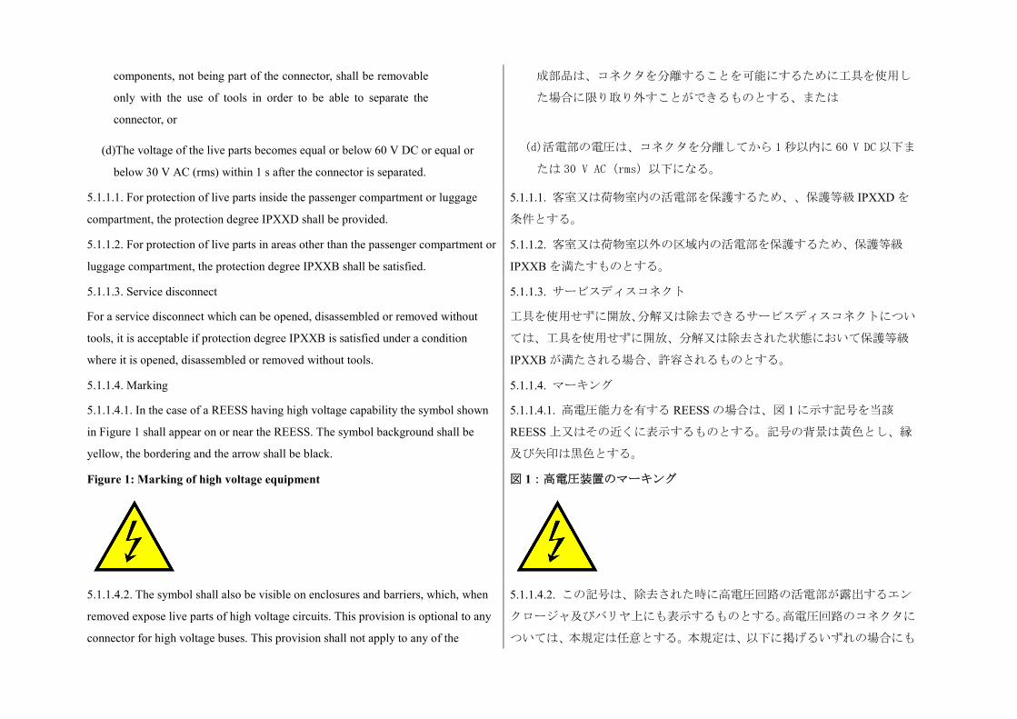
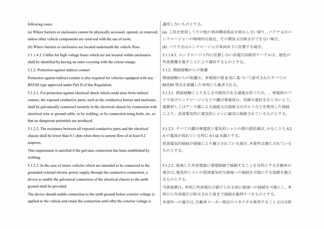
5.1.1.4. Marking
5.1.1.4.1. In the case of a REESS having high voltage capability the symbol shown
in Figure 1 shall appear on or near the REESS. The symbol background shall be
yellow, the bordering and the arrow shall be black.
5.1.1.4. マーキング
5.1.1.4.1. 高電圧能力を有する REESS の場合は、図 1 に示す記号を当該
REESS 上又はその近くに表示するものとする。記号の背景は黄色とし、縁
及び矢印は黒色とする。
Figure 1: Marking of high voltage equipment
図 1:高電圧装置のマーキング
5.1.1.4.2. The symbol shall also be visible on enclosures and barriers, which, when
removed expose live parts of high voltage circuits. This provision is optional to any
connector for high voltage buses. This provision shall not apply to any of the
5.1.1.4.2. この記号は、除去された時に高電圧回路の活電部が露出するエン
クロージャ及びバリヤ上にも表示するものとする。高電圧回路のコネクタに
ついては、本規定は任意とする。本規定は、以下に掲げるいずれの場合にも
following cases:
(a) Where barriers or enclosures cannot be physically accessed, opened, or removed;
unless other vehicle components are removed with the use of tools;
(b) Where barriers or enclosures are located underneath the vehicle floor.
適用しないものとする。
(a) 工具を使用してその他の車両構成部品を除去しない限り、バリヤ又はエ
ンクロージャへの物理的な接近、その開放又は除去ができない場合、
(b) バリヤ又はエンクロージャが車両床下に位置する場合。
5.1.1.4.3. Cables for high voltage buses which are not located within enclosures
shall be identified by having an outer covering with the colour orange.
5.1.1.4.3. エンクロージャ内に位置しない高電圧回路用ケーブルは、橙色の
外部被覆を施すことにより識別するものとする。
5.1.2. Protection against indirect contact
Protection against indirect contact is also required for vehicles equipped with any
REESS type approved under Part II of this Regulation.
5.1.2. 間接接触からの保護
間接接触からの保護は、本規則の第 II 部に基づいて認可されたすべての
REESS 型式を装備した車両にも要求される。
5.1.2.1. For protection against electrical shock which could arise from indirect
contact, the exposed conductive parts, such as the conductive barrier and enclosure,
shall be galvanically connected securely to the electrical chassis by connection with
electrical wire or ground cable, or by welding, or by connection using bolts, etc. so
that no dangerous potentials are produced.
5.1.2.1. 間接接触により生じる可能性がある感電を防ぐため、、導電体のバ
リヤ及びエンクロージャなどの露出導電部は、危険な電位を生じないよう、
電線若しくはアース線による接続又は溶接又はボルトなどを使用した接続
により、直流電気的に電気的シャシに確実に接続されているものとする。
5.1.2.2. The resistance between all exposed conductive parts and the electrical
chassis shall be lower than 0.1 ohm when there is current flow of at least 0.2
amperes.
This requirement is satisfied if the galvanic connection has been established by
welding.
5.1.2.2. すべての露出導電部と電気的シャシの間の抵抗値は、少なくとも 0.2
A の電流が流れている時に 0.1 Ω 未満とする。
直流電気的接続が溶接により確立されている場合、本要件は満たされている
ものとする。
5.1.2.3. In the case of motor vehicles which are intended to be connected to the
grounded external electric power supply through the conductive connection, a
device to enable the galvanical connection of the electrical chassis to the earth
ground shall be provided.
The device should enable connection to the earth ground before exterior voltage is
applied to the vehicle and retain the connection until after the exterior voltage is
5.1.2.3. 接地した外部電源に導電接続で接続することを目的とする自動車の
場合は、電気的シャシの直流電気的な接地への接続を可能にする装置を備え
るものとする。
当該装置は、車両に外部電圧が掛けられる前に接地への接続を可能にし、車
両から外部電圧が除去された後まで接続を維持すべきものとする。
本要件への適合は、自動車メーカー指定のコネクタを使用すること又は分析
removed from the vehicle.
Compliance to this requirement may be demonstrated either by using the connector
specified by the car manufacturer, or by analysis.
を行うことのいずれかにより証明することができる。
5.1.3. Isolation resistance
This paragraph shall not apply to chassis connected electrical circuits where the
maximum voltage between any live part and the electrical chassis or any exposed
conductive part does not exceed 30V AC (rms) or 60 V DC.
5.1.3.1. Electric power train consisting of separate Direct Current- or Alternating
Current-buses
If AC high voltage buses and DC high voltage buses are galvanically isolated from
each other, isolation resistance between the high voltage bus and the electrical
chassis shall have a minimum value of 100 ohms/volt of the working voltage for DC
buses, and a minimum value of 500 ohms/volt of the working voltage for AC buses.
The measurement shall be conducted according to Annex 4A "Isolation resistance
measurement method for vehicle based tests".
5.1.3. 絶縁抵抗
本項は、活電部と電気的シャシまたは露出導電部の間の最大電圧が 30 V AC
(rms)または 60 V DC を超えない電気回路接続シャシには適用しないもの
とする。
5.1.3.1. 分離された直流バス又は交流バスから構成された電動パワートレー
ン
AC 高電圧回路と DC 高電圧回路が直流電気的に互いに絶縁されている場合
には、高電圧回路と電気的シャシの間の絶縁抵抗は、DC バスについては最
小値が作動電圧 1 V 当たり 100 Ω、AC バスについては最小値が作動電圧 1 V
当たり 500 Ω であるものとする。
測定は、附則 4A「車両に基づく試験の絶縁抵抗測定方法」に従って実施す
るものとする。
5.1.3.2. Electric power train consisting of combined DC- and AC-buses
If AC high voltage buses and DC high voltage buses are galvanically connected
isolation resistance between the high voltage bus and the electrical chassis shall
have a minimum value of 500 ohms/volt of the working voltage.
However, if all AC high voltage buses are protected by one of the 2 following
measures, isolation resistance between the high voltage bus and the electrical
chassis shall have a minimum value of 100 ohms/V of the working voltage:
(a) Double or more layers of solid insulators, barriers or enclosures that meet the
requirement in paragraph 5.1.1. independently, for example wiring harness;
(b) Mechanically robust protections that have sufficient durability over vehicle
5.1.3.2. 複合 DC 及び AC バスから構成された電動パワートレーン
AC 高電圧回路と DC 高電圧回路が直流電気的に接続されている場合には、
高電圧回路と電気的シャシの間の絶縁抵抗は、最小値が作動電圧 1 V 当たり
500 Ω であるものとする。
ただし、以下に掲げる 2 つの措置のいずれかによりすべての AC 高電圧回路
が保護されている場合には、高電圧回路と電気的シャシの間の絶縁抵抗は、
最小値が作動電圧 1 V 当たり 100 Ω であるものとする。
(a) 個別に 5.1.1 項の要件を満たす、2 層以上の固体の絶縁体、バリヤ又はエ
ンクロージャ(例:配線ハーネス)。
(b) 車両の耐用期間にわたり十分な耐久性を有する、機械的に頑丈な保護
service life such as motor housings, electronic converter cases or connectors;
The isolation resistance between the high voltage bus and the electrical chassis may
be demonstrated by calculation, measurement or a combination of both.
The measurement shall be conducted according to Annex 4A "Isolation resistance
measurement method for vehicle based tests".
(モーターハウジング、電子式コンバーターケース又はコネクタなど)。
高電圧回路と電気的シャシの間の絶縁抵抗は、計算、測定又はその両方の組
合せにより証明することができる。
測定は、附則 4A「車両に基づく試験の絶縁抵抗測定方法」に従って実施す
るものとする。
5.1.3.3. Fuel cell vehicles
If the minimum isolation resistance requirement cannot be maintained over time,
then protection shall be achieved by any of the following:
(a) Double or more layers of solid insulators, barriers or enclosures that meet the
requirement in paragraph 5.1.1. independently;
(b) On-board isolation resistance monitoring system together with a warning to the
driver if the isolation resistance drops below the minimum required value. The
isolation resistance between the high voltage bus of the coupling system for
charging the REESS, which is not energized besides during charging the REESS,
and the electrical chassis need not be monitored. The function of the on-board
isolation resistance monitoring system shall be confirmed as described in Annex 5.
5.1.3.3. 燃料電池車両
絶縁抵抗要件の最小値を長時間維持することができない場合には、以下のい
ずれかを用いて保護を実施するものとする。
(a) 個別に 5.1.1 項の要件を満たす、2 層以上の固体の絶縁体、バリヤ又はエ
ンクロージャ。
(b) 絶縁抵抗が要求される最小値を下回る場合の運転者への警告を備えた
車載絶縁抵抗監視システム。REESS 充電用連結システムの高電圧回路
(REESS 充電中以外は電圧を印加しない)と電気的シャシの間の絶縁抵抗
は、監視する必要がない。車載絶縁抵抗監視システムの機能を附則 5 に規定
した通りに確認するものとする。
5.1.3.4. Isolation resistance requirement for the coupling system for charging the
REESS
For the vehicle inlet intended to be conductively connected to the grounded external
AC power supply and the electrical circuit that is galvanically connected to the
vehicle inlet during charging of the REESS, the isolation resistance between the
high voltage bus and the electrical chassis shall be at least 1 megohm when the
charger coupler is disconnected. During the measurement, the traction battery may
be disconnected.
5.1.3.4. REESS 充電用連結システムに関する絶縁抵抗要件
接地された外部 AC 電源に導電接続で接続することを目的とする車両イン
レット、並びに REESS 充電中、車両インレットに直流電気的に接続されて
いる電気回路については、高電圧回路と電気的シャシの間の絶縁抵抗は、充
電器カプラーの接続が外れている時に少なくとも 1 MΩ とする。測定中は駆
動用バッテリーの接続を外しても構わないものとする。
5.2. Rechargeable Electrical Energy Storage System (REESS) 5.2. 充電式電気エネルギー貯蔵システム(REESS)
5.2.1. For a vehicle with a REESS, the requirement of either paragraph 5.2.1.1. or
paragraph 5.2.1.2. shall be satisfied.
5.2.1. REESS を装備した車両については、5.2.1.1 項又は 5.2.1.2 項のいずれか
の要件を満たすものとする。
5.2.1.1. For a REESS which has been type approved in accordance with Part II of
this Regulation, it shall be installed in accordance with the instructions provided by
the manufacturer of the REESS, and in conformity with the description provided in
Part 2 of Annex 6 to this Regulation.
5.2.1.1. 本規則の第 II 部に従って型式認可を受けた REESS については、当
該 REESS のメーカーが提供した指示に従い、かつ、本規則の附則 6 の第 2
部に記載した説明に適合するように取り付けるものとする。
5.2.1.2. The REESS shall comply with the respective requirements of paragraph 6.
of this Regulation.
5.2.1.2. REESS は、本規則の 6 項の各要件に適合するものとする。
5.2.2. Accumulation of gas
Places for containing open type traction batteries that may produce hydrogen gas
shall be provided with a ventilation fan or a ventilation duct to prevent the
accumulation of hydrogen gas.
5.2.2. ガスの蓄積
水素ガスを発生する可能性がある開放式駆動用バッテリーを収容する場所
には、水素ガスの蓄積を防止するため、換気ファン又は換気ダクトを装備す
るものとする。
5.3. Functional safety
At least a momentary indication shall be given to the driver when the vehicle is in
"active driving possible mode".
However, this provision does not apply under conditions where an internal
combustion engine provides directly or indirectly the vehicle's propulsion power.
When leaving the vehicle, the driver shall be informed by a signal (e.g. optical or
audible signal) if the vehicle is still in the active driving possible mode.
If the on-board REESS can be externally charged by the user, vehicle movement by
its own propulsion system shall be impossible as long as the connector of the
external electric power supply is physically connected to the vehicle inlet.
This requirement shall be demonstrated by using the connector specified by the car
manufacturer.
The state of the drive direction control unit shall be identified to the driver.
5.3. 機能安全
車両が「自走可能状態」にある時は、運転者に対し、少なくとも瞬時的な表
示がなされるものとする。
ただし、本規定は、内燃エンジンが直接的又は間接的に車両の推進力を提供
している状態においては適用しない。
運転者が車両を離れる時、車両が依然として自走可能状態にある場合には、
信号(例:光学信号又は聴覚信号)により運転者に知らせるものとする。
ユーザーによる車載 REESS の外部充電が可能な場合には、外部電源のコネ
クタが車両インレットに物理的に接続されている限り、車両自体の推進シス
テムにより車両を動かすことは不可能であるものとする。
本要件は、自動車メーカー指定のコネクタを用いて証明するものとする。
運転方向コントロールユニットの状態を、運転者が認識できるようにするも
のとする。
5.4. Determination of hydrogen emissions
5.4.1. This test shall be carried out on all vehicles equipped with open type traction
batteries. If the REESS has been approved under Part II of this Regulation and
installed in accordance with paragraph 5.2.1.1. this test can be omitted for the
approval of the vehicle.
5.4. 水素エミッションの測定
5.4.1. この試験は、開放式駆動用バッテリーを装備するすべての車両に対し
て実施されるものとする。REESS が本規則の第 II 部に基づいて認可され、
5.2.1.1 項に従って取り付けられている場合、車両の認可についてはこの試験
を省くことができる。
5.4.2. The test shall be conducted following the method described in Annex 7 to the
present Regulation. The hydrogen sampling and analysis shall be the ones
prescribed. Other analysis methods can be approved if it is proven that they give
equivalent results.
5.4.2. この試験は、本規則の附則 7 に規定された方法に従ってを実施される
ものとする。水素の抜取検査及び分析は、規定された通りとする。その他の
分析方法については、それにより同等の結果が得られることが証明された場
合は、承認され得る。
5.4.3. During a normal charge procedure in the conditions given in Annex 7,
hydrogen emissions shall be below 125 g during 5 h, or below 25 x t2 g during t2 (in
h).
5.4.3. 附則 7 に規定される状態の正常な充電手順において、水素エミッショ
ンは、5 h 中は 125 g 未満、又は t2(単位:h)中は 25×t2 g 未満とする。
5.4.4. During a charge carried out by a charger presenting a failure (conditions given
in Annex 7), hydrogen emissions shall be below 42 g. Furthermore the charger shall
limit this possible failure to 30 minutes.
5.4.5. All the operations linked to the REESS charging shall be controlled
automatically, included the stop for charging.
5.4.4. 故障(附則 7 に記載された状態)を示す充電器で行う充電中の水素エ
ミッションは、42 g 未満とする。さらに充電器は、この生じ得る故障を 30
分間に制限するものとする。
5.4.5. REESS 充電に関連する操作はすべて、充電停止を含み、自動的に制御
されるものとする。
5.4.6. It shall not be possible to take a manual control of the charging phases.
5.4.7. Normal operations of connection and disconnection to the mains or power
cuts shall not affect the control system of the charging phases.
5.4.8. Important charging failures shall be permanently indicated. An important
failure is a failure that can lead to a malfunction of the charger during charging later
on.
5.4.6. 充電段階の手動制御は可能でないものとする。
5.4.7. 電源又は電力切断装置への接続及び接続切断を行う通常の操作は、充
電段階のコントロールシステムに影響を及ぼさないものとする。
5.4.8. 重大な充電故障は、恒久的に表示されるものとする。重大な故障とは、
後の充電において充電器の動作不良を生じる可能性がある故障をいう。
5.4.9. The manufacturer has to indicate in the owner's manual, the conformity of the
vehicle to these requirements.
5.4.9. メーカーは、車両がこれらの要件に適合していることをオーナーズマ
ニュアルに記載しなければならない。
5.4.10. The approval granted to a vehicle type relative to hydrogen emissions can be
extended to different vehicle types belonging to the same family, in accordance with
the definition of the family given in Annex 7, Appendix 2.
5.4.10. 水素エミッションに関する車両型式に付与された認可は、附則 7 の
付録 2 に規定されたファミリーの定義に従って、同一ファミリーに属する複
数の異なる車両型式に拡大することができる。
6. Part II: Requirements of a Rechargeable Electrical Energy Storage
System (REESS) with regard to its safety
6. 第 II 部:安全に係る充電式電気エネルギー貯蔵システム(REESS)の要
件
6.1. General
The procedures prescribed in Annex 8 of this Regulation shall be applied.
6.2. Vibration
6.2.1. The test shall be conducted in accordance with Annex 8A to this Regulation.
6.1. 一般要件
本規則の附則 8 に定める手順が適用されるものとする。
6.2. 振動
6.2.1. 本規則の附則 8A に従って試験を実施するものとする。
6.2.2. Acceptance criteria
6.2.2.1. During the test, there shall be no evidence of:
(a) Electrolyte leakage;
(b) Rupture (applicable to high voltage REESS (s) only);
(c) Fire;
(d) Explosion.
Evidence of electrolyte leakage shall be verified by visual inspection without
disassembling any part of the tested-device.
6.2.2. 合格基準
6.2.2.1. 試験中に、以下の徴候を示さないものとする。
(a) 電解液漏れ、
(b) 破裂(高電圧 REESS に限り適用する)、
(c) 火炎、
(d) 爆発。
電解液漏れの徴候は、試験対象装置のいかなる部品も分解せず、目視検査に
よって検証するものとする。
6.2.2.2. For a high voltage REESS, the isolation resistance measured after the test in
accordance with Annex 4B to this Regulation shall not be less than 100 ohms/Volt.
6.3. Thermal shock and cycling
6.3.1. The test shall be conducted in accordance with Annex 8B to this Regulation.
6.2.2.2. 高電圧 REESS については、本規則の附則 4B に従って試験後に測定
した絶縁抵抗が 100 Ω/V 以上であるものとする。
6.3. 熱衝撃及びサイクル試験
6.3.1. この試験は、本規則の附則 8B に従って実施されるものとする。
6.3.2. Acceptance criteria
6.3.2.1. During the test, there shall be no evidence of:
6.3.2. 合格基準
6.3.2.1. 試験中に、以下の徴候を示さないものとする。
(a) Electrolyte leakage;
(b) Rupture (applicable to high voltage REESS(s) only);
(c) Fire;
(d) Explosion.
Evidence of electrolyte leakage shall be verified by visual inspection without
disassembling any part of the tested-device.
(a) 電解液漏れ、
(b) 破裂(高電圧 REESS に限り適用する)、
(c) 火炎、
(d) 爆発。
電解液漏れの徴候は、試験対象装置のいかなる部品も分解せず、目視検査に
よって検証するものとする。
6.3.2.2. For a high voltage REESS, the isolation resistance measured after the test in
accordance with Annex 4B of this Regulation shall not be less than 100 ohms/Volt.
6.3.2.2. 高電圧 REESS については、本規則の附則 4B に従って試験後に測定
した絶縁抵抗が 100 Ω/V 以上であるものとする。
6.4. Mechanical impact
6.4.1. Mechanical Shock
At the manufacturer's choice the test may be performed as, either
(a) Vehicle based tests in accordance with paragraph 6.4.1.1. of this Regulation, or
(b) Component based tests in accordance with paragraph 6.4.1.2. of this Regulation,
or
(c) Any combination of (a) and (b) above, for different direction of vehicle travel.
6.4. 機械的衝撃
6.4.1. メカニカルショック
メーカーの選択により、試験を以下のいずれかとして実施してもよい。
(a) 本規則の 6.4.1.1 項に従った車両に基づく試験、又は
(b) 本規則の 6.4.1.2 項に従った構成部品に基づく試験、又は
(c) 車両の異なる走行方向については、上記(a)と(b)の組み合わせ。
6.4.1.1. Vehicle based test
Compliance with the requirements of the acceptance criteria of paragraph 6.4.1.3.
below may be demonstrated by REESS(s) installed in vehicles that have been
subjected to vehicle crash tests in accordance with Regulation No. 12, Annex 3 or
Regulation No. 94, Annex 3 for frontal impact, and Regulation No. 95, Annex 4 for
side impact. The ambient temperature and the SOC shall be in accordance with the
said Regulations.
The approval of a REESS tested under this paragraph shall be limited to the specific
vehicle type.
6.4.1.1. 車両に基づく試験
下記 6.4.1.3 項の合格基準要件への適合は、正面衝突については協定規則第
12 号の附則 3 又は協定規則第 94 号の附則 3、側面衝突については協定規則
第 95 号の附則 4 に従って、車両衝突試験を実施した車両に取り付けた
REESS によって証明してもよい。周囲温度及び SOC は、当該規則に従うも
のとする。
本項に基づいて試験した REESS の認可は、当該する特定の車両型式に限定
されるものとする。
6.4.1.2. Component based test
The test shall be conducted in accordance with Annex 8C to this Regulation.
6.4.1.2. 構成部品に基づく試験
この試験は、本規則の附則 8C に従って実施されるものとする。
6.4.1.3. Acceptance criteria
During the test there shall be no evidence of:
(a) Fire;
(b) Explosion;
(c1) Electrolyte leakage if tested according to paragraph 6.4.1.1.:
(i) For a period from the impact until 30 minutes after the impact there shall be no
electrolyte spillage from the REESS into the passenger compartment;
(ii) No more than 7 per cent by volume of the REESS electrolyte capacity shall spill
from the REESS to the outside of the passenger compartment (for open type traction
batteries a limitation to a maximum of 5 litres also applies);
(c2) Electrolyte leakage if tested according to paragraph 6.4.1.2.
After the vehicle based test (paragraph 6.4.1.1.), a REESS which is located inside
the passenger compartment shall remain in the installed location and the REESS
components shall remain inside REESS boundaries. No part of any REESS that is
located outside the passenger compartment shall enter the passenger compartment
during or after the impact test procedures.
After the component based test (paragraph 6.4.1.2.) the tested-device shall be
retained by its mounting and its components shall remain inside its boundaries.
For a high voltage REESS the isolation resistance of the tested-device shall ensure
at least 100 ohms/Volt for the whole REESS measured after the test in accordance
with Annex 4A or Annex 4B to this Regulation, or the protection degree IPXXB
shall be fulfilled for the tested-device.
For a REESS tested in accordance with paragraph 6.4.1.2., the evidence of
6.4.1.3. 合格基準
試験中に、以下の徴候を示さないものとする。
(a) 火炎、
(b) 爆発、
(c1) 6.4.1.1 項に従って試験した場合、電解液漏れ
(i) 衝撃から衝撃後 30 分までの間については、REESS から客室に電解液の
漏出がないものとする。
(ii) REESS の電解液容積の 7 体積%を超えて、REESS から客室の外に電解液
が漏出しないものとする(開放式駆動用バッテリーについては、最大 5 リッ
トルの制限も適用する)。
(c2) 6.4.1.2 項に従って試験した場合の電解液漏れ
車両に基づく試験(6.4.1.1 項)後、客室内に位置する REESS は、引き続き
取り付け位置にあるものとし、REESS 構成部品は、引き続き REESS の境界
内にあるものとする。客室の外に位置する REESS のいずれの部分も、衝撃
試験手順の間又はその後に、客室内に侵入しないものとする。
構成部品に基づく試験(6.4.1.2 項)後、試験対象装置は、その土台によって
保持されるものとし、その構成部品は、引き続きその境界内にあるものとす
る。
高電圧 REESS について、試験対象装置の絶縁抵抗は本規則の附則 4A 又は
附則 4B に従って試験後に測定した REESS 全体について、少なくとも 100 Ω
/V を保証するものであるか、あるいは試験対象装置について保護等級
IPXXB を満たすものとする。
6.4.1.2 項に従って試験した REESS について、電解液漏れの徴候は、試験対
electrolyte leakage shall be verified by visual inspection without disassembling any
part of the tested-device.
To confirm compliance to (c1) of paragraph 6.4.1.3. an appropriate coating shall, if
necessary, be applied to the physical protection (casing) in order to confirm if there
is any electrolyte leakage from the REESS resulting from the impact test. Unless the
manufacturer provides a means to differentiate between the leakage of different
liquids, all liquid leakage shall be considered as the electrolyte.
象装置のいかなる部品も分解せず、目視検査によって検証するものとする。
6.4.1.3 項の(c1)への適合を確認するために、衝突試験の結果として REESS
からの電解液漏れがあるかどうかを確認するため、必要に応じて、物理的保
護物 (ケーシング)に適切なコーティングを塗布するものとする。メーカ
ーが異なる液体の漏れを区別する手段を提供していない限り、すべての液漏
れは電解液とみなされるものとする。
6.4.2. Mechanical integrity
This test applies only to a REESS intended for installation in vehicles of categories
M1 and N1.
At the manufacturer's choice, the test may be performed as, either:
(a) Vehicle based tests in accordance with paragraph 6.4.2.1. of this Regulation, or
(b) Component based tests in accordance with paragraph 6.4.2.2. of this Regulation.
6.4.2. メカニカルインテグリティ
この試験は、区分 M1 及び N1 の車両に取り付けることを目的とする REESS
にのみ適用される。
メーカーの選択により、試験を以下のいずれかとして実施してもよい。
(a) 本規則の 6.4.2.1 項に従った車両に基づく試験、又は
(b) 本規則の 6.4.2.2 項に従った構成部品に基づく試験。
6.4.2.1. Vehicle specific test
At the manufacturer's choice, the test may be performed as either:
(a) A vehicle based dynamic tests in accordance with paragraph 6.4.2.1.1. of this
Regulation, or
(b) A vehicle specific component test in accordance with paragraph 6.4.2.1.2. of this
Regulation, or
(c) Any combination of (a) and (b) above, for different directions of vehicle travel.
When the REESS is mounted in a position which is between a line from the rear
edge of the vehicle perpendicular to the centre line of the vehicle and 300 mm
forward and parallel to this line, the manufacturer shall demonstrate the mechanical
integrity performance of the REESS in the vehicle to the Technical Service.
The approval of a REESS tested under this paragraph shall be limited to specific
6.4.2.1. 車両特定試験
メーカーの選択により、試験を以下のいずれかとして実施してもよい。
(a) 本規則の 6.4.2.1.1 項に従った車両に基づく動的試験、又は
(b) 本規則の 6.4.2.1.2 項に従った車両の特定構成部品試験、又は
(c) 車両の異なる走行方向については、上記(a)と(b)の組み合わせ。
REESS が、車両の中心線に垂直な車両後端からの線及びこの線の 300 mm
前方で当該線に平行な線との間の任意の位置に取り付けられている場合、メ
ーカーは、車両に取り付けた REESS のメカニカルインテグリティ性能を技
術機関に証明するものとする。
本項に基づいて試験した REESS の認可は、特定の車両型式に限定されるも
のとする。
vehicle type.
6.4.2.1.1. Vehicle based dynamic test
Compliance with the requirements of the acceptance criteria of paragraph 6.4.2.3.
below may be demonstrated by REESS(s) installed in vehicles that have been
subjected to a vehicle crash test in accordance with the Annex 3 to Regulations Nos.
12 or 94 for frontal impact, and Annex 4 to Regulation No. 95 for side impact. The
ambient temperature and the SOC shall be in accordance with the said Regulations.
6.4.2.1.1. 車両に基づく動的試験
下記 6.4.2.3 項の合格基準要件への適合は、正面衝突については協定規則第
12 号又は第 94 号の附則 3、側面衝突について協定規則第 95 号の附則 4 に
従って、車両衝突試験を実施した車両に取り付けた REESS によって証明し
てもよい。周囲温度及び SOC は、当該規則に従うものとする。
6.4.2.1.2. Vehicle specific component test
The test shall be conducted in accordance with Annex 8D of this Regulation.
The crush force replacing the prescribed force specified in paragraph 3.2.1. of
Annex 8D shall be determined by the vehicle manufacturer using the data obtained
from either actual crash tests or its simulation as specified in Annex 3 of
Regulations No. 12 or No. 94 in the direction of travel and according to Annex 4 to
Regulation No. 95 in the direction horizontally perpendicular to the direction of
travel. These forces shall be agreed by the Technical Service.
The manufacturers may, in agreement with the Technical Services, use forces
derived from the data obtained from alternative crash test procedures, but these
forces shall be equal to or greater than the forces that would result from using data
in accordance with the Regulations specified above.
The manufacturer may define the relevant parts of the vehicle structure used for the
mechanical protection of the REESS components. The test shall be conducted with
the REESS mounted to this vehicle structure in a way which is representative of its
mounting in the vehicle.
6.4.2.1.2. 車両特定構成部品試験
本規則の附則 8D に従って試験を実施するものとする。
車両メーカーは、走行方向については協定規則第 12 号又は第 94 号の附則 3
に規定した、走行方向に水平に垂直な方向については協定規則第 95 号の附
則 4 に従った実際の衝突試験又はそのシミュレーションのいずれかから得
たデータを用いて、附則 8D の 3.2.1 項に規定した所定の力に置き換わる破
砕力を決定するものとする。かかる力については、技術機関の同意を得るも
のとする。
メーカーは、技術機関の同意があれば、代替衝突試験手順から得たデータか
ら求めた力を用いることができるが、かかる力は、上記に指定される規則に
従ったデータを用いた結果である力と同等又はそれ以上のものとする。
メーカーは、REESS 構成部品の機械的保護に使用される車両構造体の該当
する部品を定めてもよい。試験は、REESS を典型的な取付け方法で当該車
両構造体に取り付けた状態において実施されるものとする。
6.4.2.2. Component based test
The test shall be conducted in accordance with Annex 8D to this Regulation.
6.4.2.2. 構成部品に基づく試験
この試験は、本規則の附則 8D に従って実施されるものとする。
REESS approved according to this paragraph shall be mounted in a position which
is between the two planes; (a) a vertical plane perpendicular to the centre line of the
vehicle located 420 mm rearward from the front edge of the vehicle, and (b) a
vertical plane perpendicular to the centre line of the vehicle located 300 mm forward
from the rear edge of the vehicle.
The mounting restrictions shall be documented in Annex 6 - Part 2.
The crush force specified in paragraph 3.2.1. of Annex 8D may be replaced with the
value declared by the manufacturer, where the crush force shall be documented in
Annex 6, Part 2 as a mounting restriction. In this case, the vehicle manufacturer who
uses such REESS shall demonstrate, during the process of approval for Part I of this
Regulation, that the contact force to the REESS will not exceed the figure declared
by the REESS manufacturer. Such force shall be determined by the vehicle
manufacturer using the data obtained from either actual crash test or its simulation
as specified in Annex 3 of Regulations Nos. 12 or 94 in the direction of travel and
according to Annex 4 to Regulation No. 95 in the direction horizontally
perpendicular to the direction of travel. These forces shall be agreed by the
manufacturer together with the Technical Service.
The manufacturers may, in agreement with the Technical Services, use forces
derived from the data obtained from alternative crash test procedures, but these
forces shall be equal to or greater than the forces that would result from using data
in accordance with the regulations specified above.
本項に従って認可された REESS を以下の 2 つの面の間の位置に取り付ける
ものとする: (a) 車両の前端から 420 mm 後方に位置する車両の中心線に垂
直な垂直面と、(b) 車両の後端から 300 mm 前方に位置する車両の中心線に
垂直な垂直面。
取り付けに関する制限は、附則 6 の第 2 部に文書化されるものとする。
附則 8D の 3.2.1 項に規定される破砕力は、メーカーが申告する値に置き換
えてもよい。ここで、破砕力は、取り付け制限として附則 6 の第 2 部に文書
化されるものとする。この場合、かかる REESS を使用する車両メーカーは、
本規則の第 1部に関する認可プロセス中にREESSへ接触力がREESSメーカ
ーが申告した値を超えないことを証明するものとする。車両メーカーは、走
行方向については協定規則第 12 号又は第 94 号の附則 3 の規定、走行方向に
水平に垂直な方向については協定規則第 95 号の附則 4 の規定に従った、実
際の衝突試験又はそのシミュレーションのいずれかより得たデータを用い
て、当該の破砕力を求めるものとする。かかる力については、技術機関とメ
ーカーが同意するものとする。
メーカーは、技術機関の同意があれば、代替衝突試験手順から得たデータか
ら求めた力を用いることができるが、かかる力は、上記に指定される規則に
従ったデータを用いた結果である力と同等又はそれ以上のものとする。
6.4.2.3. Acceptance criteria
During the test there shall be no evidence of:
(a) Fire;
(b) Explosion;
6.4.2.3. 合格基準
試験中に、以下の徴候を示さないものとする。
(a) 火炎
(b) 爆発
(c1) Electrolyte leakage if tested according to paragraph 6.4.1.1.:
(i) For a period from the impact until 30 minutes after the impact there shall be no
electrolyte spillage from the REESS into the passenger compartment.
(ii) No more than 7 per cent by volume of the REESS electrolyte capacity shall spill
from the REESS to the outside of the passenger compartment (for open type traction
batteries a limitation to a maximum of 5 litres also applies).
(c2) Electrolyte leakage if tested according to paragraph 6.4.2.2.
For a high voltage REESS, the isolation resistance of the tested-device shall ensure
at least 100 ohms/Volt for the whole REESS measured in accordance with Annex
4A or Annex 4B of this Regulation or the protection degree IPXXB shall be fulfilled
for the Tested-Device.
If tested according to paragraph 6.4.2.2., the evidence of electrolyte leakage shall be
verified by visual inspection without disassembling any part of the tested-device.
To confirm compliance to (c1) of paragraph 6.4.2.3. an appropriate coating shall, if
necessary, be applied to the physical protection (casing) in order to confirm if there
is any electrolyte leakage from the REESS resulting from the impact test. Unless the
manufacturer provides a means to differentiate between the leakage of different
liquids, all liquid leakage shall be considered as the electrolyte.
(c1) 6.4.1.1 項に従って試験した場合の電解液漏れ
(i) 衝撃から衝撃後 30 分までの間については、REESS から客室に電解液の
漏出がないものとする。
(ii) REESS の電解液容積の 7 体積%を超えて、REESS から客室の外に電解液
が漏出しないものとする(開放式駆動用バッテリーについては、最大 5 リッ
トルの制限も適用する)。
(c2) 6.4.2.2 項に従って試験した場合の電解液漏れ
高電圧 REESS については、試験対象装置の絶縁抵抗は、本規則の附則 4A
又は附則 4B に従って測定した REESS 全体について少なくとも 100 Ω/Vを
保証するものとするか、あるいは試験対象装置について、保護等級 IPXXB
を満たすものとする。
6.4.2.2 項に従って試験した場合、電解液漏れの徴候は、試験対象装置のいか
なる部品も分解せず、目視検査によって検証するものとする。
6.4.2.3 項の(c1)への適合を確認するために、衝突試験の結果として REESS
からの電解液漏れがあるかどうかを確認するため、物理的保護物(ケーシン
グ)に適切なコーティングを塗布するものとする。メーカーが異なる液体の
漏れを区別する手段を提供していない限り、すべての液漏れは電解液とみな
されるものとする。
6.5. Fire resistance
This test is required for REESS containing flammable electrolyte.
This test is not required when the REESS as installed in the vehicle, is mounted
such that the lowest surface of the casing of the REESS is more than 1.5m above the
ground. At the option of the manufacturer, this test may be performed where the of
the REESS's lower surface is higher than 1.5 m above the ground. The test shall be
carried out on one test sample.
6.5. 耐火性
この試験は、可燃性電解液が入った REESS に対して要求される。
車両に取り付けられた REESS が、REESS のケーシングの下面が地上 1.5 m
を超えるように取り付けられている場合には、この試験は要求されない。メ
ーカーのオプションにより、本試験を REESS の下面が地上 1.5 m を超える
場合に実施してもよい。当該試験は、1 つの供試品で実施するものとする。
メーカーの選択により、試験を以下のいずれかとして実施してもよい。
At the manufacturer's choice the test may be performed as, either:
(a) A vehicle based test in accordance with paragraph 6.5.1. of this Regulation, or
(b) A component based test in accordance with paragraph 6.5.2. of this Regulation.
(a) 本規則の 6.5.1 項に従った車両に基づく試験、又は
(b) 本規則の 6.5.2 項に従った構成部品に基づく試験。
6.5.1. Vehicle based test
The test shall be conducted in accordance with Annex 8E paragraph 3.2.1. of this
Regulation.
The approval of a REESS tested according to this paragraph shall be limited to
approvals for a specific vehicle type.
6.5.1. 車両に基づく試験
この試験は、本規則の附則 8E、3.2.1 項に従って実施されるものとする。
本項に基づいて試験した REESS の認可は、特定の車両型式に関する認可に
限定されるものとする。
6.5.2. Component based test
The test shall be conducted in accordance with Annex 8E paragraph 3.2.2. of this
Regulation.
6.5.2. 構成部品に基づく試験
この試験は、本規則の附則 8E、3.2.2 項に従って実施されるものとする。
6.5.3. Acceptance criteria
6.5.3.1. During the test, the tested-device shall exhibit no evidence of explosion.
6.5.3. 合格基準
6.5.3.1. 試験中に、試験対象装置は爆発の徴候を示さないものとする。
6.6. External short circuit protection
6.6.1. The test shall be conducted in accordance with Annex 8F of this Regulation.
6.6.2. Acceptance criteria;
6.6. 外部短絡保護
6.6.1. この試験は、本規則の附則 8F に従って実施されるものとする。
6.6.2. 合格基準
6.6.2.1. During the test there shall be no evidence of:
(a) Electrolyte leakage;
(b) Rupture (applicable to high voltage REESS(s) only);
(c) Fire;
(d) Explosion.
Evidence of electrolyte leakage shall be verified by visual inspection without
disassembling any part of the tested-device.
6.6.2.1. 試験中に、以下の徴候を示さないものとする。
(a) 電解液漏れ、
(b) 破裂(高電圧 REESS に限り適用する)、
(c) 火炎、
(d) 爆発。
電解液漏れの徴候は、試験対象装置のいかなる部品も分解せず、目視検査に
よって検証するものとする。
6.6.2.2. For a high voltage REESS, the isolation resistance measured after the test in 6.6.2.2. 高電圧 REESS については、本規則の附則 4B に従って試験後に測定
accordance with Annex 4 B to this Regulation shall not be less than 100 ohms/Volt. した絶縁抵抗が 100 Ω/V 以上であるものとする。
6.7. Overcharge protection
6.7.1. The test shall be conducted in accordance with Annex 8G to this Regulation.
6.7.2. Acceptance criteria
6.7. 過充電保護
6.7.1. この試験は、本規則の附則 8G に従って実施されるものとする。
6.7.2. 合格基準
6.7.2.1. During the test there shall be no evidence of:
(a) Electrolyte leakage;
(b) Rupture (applicable to high voltage REESS(s) only);
(c) Fire;
(d) Explosion.
Evidence of electrolyte leakage shall be verified by visual inspection without
disassembling any part of the tested-device.
6.7.2.1. 試験中に、以下の徴候を示さないものとする。
(a) 電解液漏れ、
(b) 破裂(高電圧 REESS に限り適用する)、
(c) 火炎、
(d) 爆発。
電解液漏れの徴候は、試験対象装置のいかなる部品も分解せず、目視検査に
よって検証するものとする。
6.7.2.2. For a high voltage REESS, the isolation resistance measured after the test in
accordance with Annex 4B to this Regulation shall not be less than 100 ohms/Volt.
6.7.2.2. 高電圧 REESS については、本規則の附則 4B に従って試験後に測定
した絶縁抵抗が 100 Ω/V 以上であるものとする。
6.8. Over-discharge protection
6.8.1. The test shall be conducted in accordance with Annex 8H to this Regulation.
6.8.2. Acceptance criteria
6.8. 過放電保護
6.8.1. この試験は、本規則の附則 8H に従って実施されるものとする。
6.8.2. 合格基準
6.8.2.1. During the test there shall be no evidence of:
(a) Electrolyte leakage;
(b) Rupture (applicable to high voltage REESS(s) only);
(c) Fire;
(d) Explosion.
Evidence of electrolyte leakage shall be verified by visual inspection without
disassembling any part of the tested-device.
6.8.2.1. 試験中に、以下の徴候を示さないものとする。
(a) 電解液漏れ、
(b) 破裂(高電圧 REESS に限り適用する)、
(c) 火炎、
(d) 爆発。
電解液漏れの徴候は、試験対象装置のいかなる部品も分解せず、目視検査に
よって検証するものとする。
6.8.2.2. For a high voltage REESS the isolation resistance measured after the test in 6.8.2.2. 高電圧 REESS については、本規則の附則 4B に従って試験後に測定
accordance with Annex 4B to this Regulation shall not be less than 100 ohms/Volt. した絶縁抵抗が 100 Ω/V 以上であるものとする。
6.9. Over-temperature protection
6.9.1. The test shall be conducted in accordance with Annex 8I to this Regulation.
6.9.2. Acceptance criteria
6.9. 過昇温保護
6.9.1. この試験は、本規則の附則 8I に従って実施されるものとする。
6.9.2. 合格基準
6.9.2.1. During the test there shall be no evidence of:
(a) Electrolyte leakage;
(b) Rupture (applicable to high voltage REESS(s) only);
(c) Fire;
(d) Explosion.
Evidence of electrolyte leakage shall be verified by visual inspection without
disassembling any part of the tested-device.
6.9.2.1. 試験中に、以下の徴候を示さないものとする。
(a) 電解液漏れ、
(b) 破裂(高電圧 REESS に限り適用する)、
(c) 火炎、
(d) 爆発。
電解液漏れの証拠は、試験対象装置のいかなる部品も分解せず、目視検査に
よって検証するものとする。
6.9.2.2. For a high voltage REESS, the isolation resistance measured after the test in
accordance with Annex 4B to this Regulation shall not be less than 100 ohms/Volt.
6.9.2.2. 高電圧 REESS については、本規則の附則 4B に従って試験後に測定
した絶縁抵抗が 100 Ω/V 以上であるものとする。
6.10. Emission
Possible emission of gases caused by the energy conversion process during normal
use shall be considered.
6.10. エミッション
通常の使用中のエネルギー変換プロセスによって生じる可能性のあるガス
のエミッションを考慮するものとする。
6.10.1. Open type traction batteries shall meet the requirements of paragraph 5.4. of
this Regulation with regard to hydrogen emissions.
Systems with a closed chemical process shall be considered as emission-free under
normal operation (e.g. lithium-ion battery).
The closed chemical process shall be described and documented by the battery
manufacturer in Annex 6 - Part 2.
Other technologies shall be evaluated by the manufacturer and the Technical Service
regarding any possible emissions under normal operation.
6.10.1. 開放式駆動用バッテリーは、水素エミッションに関して、本規則の
5.4 項の要件を満たすものとする。
クローズド化学プロセスを持つシステムは、通常の作動ではエミッションが
生じないとみなすものとする(例えばリチウムイオンバッテリー)。
クローズド化学プロセスは、附則 6 の第 2 部において、バッテリーメーカー
が説明し、文書化するものとする。
その他の技術については、メーカー及び技術機関が通常の作動におけるエミ
ッションの可能性に関する評価を行うものとする。
6.10.2. Acceptance criteria
For hydrogen emissions see paragraph 5.4. of this Regulation.
For emission free systems with closed chemical process no verification is necessary.
6.10.2. 合格基準
水素エミッションについては、本規則の 5.4 項を参照のこと。
クローズド化学プロセスを持つエミッションを生じないシステムについて
は、検証は不要である。
7. Modifications and extension of the type approval
7.1. Every modification of the vehicle or REESS type with regard to this Regulation
shall be notified to the Type Approval Authority which approved the vehicle or
REESS type. The Authority may then either:
7. 型式認可の変更及び拡大
7.1. 本規則に係る車両又は REESS の型式について変更があった場合、当該
車両又は REESS の型式の認可を行った行政官庁に届出しなければならな
い。行政官庁は、以下に規定するいずれかの措置を取ることができる。
7.1.1. Consider that the modifications made are unlikely to have an appreciable
adverse effect and that in any case the vehicle or the REESS still complies with the
requirements, or
7.1.1. 実施された変更により著しい悪影響が発生するおそれがない場合に
は、当該車両又は REESS が引き続き要件に適合するという判断を下す、又
は
7.1.2. Require a further test report from the Technical Service responsible for
conducting the tests.
7.2. Confirmation or refusal of approval, specifying the alteration, shall be
communicated by the procedure specified in paragraph 4.3. above to the Parties to
the Agreement applying this Regulation.
7.1.2. 試験を実施する責任を有する技術機関に対し、追加の試験成績書を要
求する。
7.2. 行政官庁は、変更に係る認可の確認又は拒否を行った場合には、変更点
を明記の上、上記 4.3 項に規定された手順により、本規則を適用する協定締
約国に通知するものとする。
7.3. The Type Approval Authority issuing the extension of approval shall assign a
series number to each communication form drawn up for such an extension and
inform thereof the other Parties to the 1958 Agreement applying the Regulation by
means of a communication form conforming to the model in Annex 1 (Part 1 or Part
2) to this Regulation.
7.3. 認可拡大を行う行政官庁は、当該拡大に対して作成した通知書に通し番
号を割り当て、本規則の附則 1(第 1 部又は 2)の様式に定める通知書によ
って、本規則を適用する 1958 年協定締約国にその旨を通知するものとする。
8. Conformity of production
8.1. Vehicles or REESS approved under this Regulation shall be so manufactured as
8. 生産の適合性
8.1. 本規則に基づいて認可される各車両又は REESS は、本規則の該当箇所
to conform to the type approved by meeting the requirements of the relevant part(s)
of this Regulation.
の定める要件を満たすことによって、認可された型式に適合するよう製造す
るものとする。
8.2. In order to verify that the requirements of paragraph 8.1. are met, appropriate
production checks shall be carried out.
8.3. The holder of the approval shall, in particular:
8.2. 8.1 項に規定された要件が満たされていることを検証するために、適切
な生産チェックを実施するものとする。
8.3. 認可を受けた者は、特に以下を実施するものとする。
8.3.1. Ensure the existence of procedures for the effective quality control of vehicles
or REESS;
8.3.1. 車両又はREESSの有効な品質管理手順が確実に存在するようにする。
8.3.2. Have access to the testing equipment necessary for checking the conformity
of each approved type;
8.3.2. 認可された各型式の適合性を確認するために必要な試験機器を利用
できる状態にしておく。
8.3.3. Ensure that test result data are recorded and that the annexed documents
remain available for a period to be determined in agreement with the Type Approval
Authority;
8.3.3. 試験結果データが記録されていること、並びに、型式の認可を行う行
政官庁当局との合意に基づき決定された期間にわたり、添付文書を利用でき
る状態にしておくことを確保する。
8.3.4. Analyse the results of each type of test, in order to verify and ensure the
consistency of characteristics of the vehicle or REESS, making allowance for
permissible variations in industrial production;
8.3.4. 工業生産における許容変動を考慮に入れながら、車両又は REESS の
特性の一貫性を検証及び保証するために、各種の試験結果の分析を行う。
8.3.5. Ensure that for each type of vehicle or component type at least the tests
prescribed in the relevant part(s) of this Regulation are carried out;
8.3.5. 車両の各型式又は構成部品型式について、少なくとも本規則の該当箇
所の定める試験を実施する。
8.3.6. Ensure that any set of samples or test pieces giving evidence of
non-conformity with the type of test in question shall give rise to a further sampling
and test. All necessary steps shall be taken to re-establish conformity of the
corresponding production.
8.3.6. 当該の種類の試験に不適合の徴候を示す一連の供試品又は試験片が
ある場合は、追加の抜取検査及び試験を実施することを確保する。該当する
生産の適合性を再確立するため、必要とされるすべての手段を取るものとす
る。
8.4. The Type Approval Authority which has granted type approval may at any time
verify the conformity control methods applied in each production unit.
8.4. 型式の認可を付与した行政官庁は、各生産施設で使われている適合性管
理の方法を、いつでも検証することができる。
8.4.1. At every inspection, the test records and production records shall be presented
to the visiting inspector.
8.4.1. 検査の都度、立ち入り検査官に対し、試験の記録及び生産の記録を提
示するものとする。
8.4.2. The inspector may take samples at random to be tested in the manufacturer's
laboratory. The minimum number of samples may be determined according to the
results of the manufacturer's own checks.
8.4.2. 検査官は、メーカーの試験施設において、供試品を無作為に抽出して
試験を行うことができる。供試品の最小個数は、メーカーによる自社検査の
結果に基づいて決定することができる。
8.4.3. When the quality level appears unsatisfactory or when it seems necessary to
verify the validity of the tests carried out in application of paragraph 8.4.2., the
inspector shall select samples to be sent to the technical service which has
conducted the type approval tests.
8.4.3. 品質レベルが不十分であると見受けられる場合、あるいは 8.4.2 項を
適用して実施された試験の妥当性を検証する必要があると見受けられる場
合、検査官は供試品を選択し型式認可試験を実施した技術機関に送るものと
する。
8.4.4. The competent Authority may carry out any test prescribed in this Regulation. 8.4.4. 所管官庁は、本規則に規定されたいずれの試験も実施することができ
る。
8.4.5. The normal frequency of inspections by the Type Approval Authority shall be
one per year. If unsatisfactory results are recorded during one of these visits, the
Type Approval Authority shall ensure that all necessary steps are taken to
re-establish the conformity of production as rapidly as possible.
8.4.5. 型式の認可を行う行政官庁による検査は通常、年に 1 回の頻度で行う
ものとする。この立ち入り検査において不十分な結果が記録された場合、型
式の認可を行う行政官庁は、可能な限り迅速に、生産の適合性を再確立する
ために必要とされるすべての手段を取ることを確保するものとする。
9. Penalties for non-conformity of production
9.1. The approval granted in respect of a vehicle/REESS type, pursuant to this
Regulation may be withdrawn if the requirements laid down in paragraph 8. above
are not complied with, or if the vehicle/REESS or its components fail to pass the
tests provided for in paragraph 8.3.5. above.
9. 生産の不適合に対する罰則
9.1. 本規則に基づく車両及び REESS の型式に関して付与された認可は、上
記 8 項に定めた要件に適合しない場合、あるいは車両及び REESS 若しくは
その構成部品が上記 8.3.5 項に定めた試験に合格しない場合には、取り消す
ことができるものとする。
9.2. If a Contracting Party to the Agreement applying this Regulation withdraws an
approval it has previously granted, it shall forthwith so notify the other Contracting
Parties applying this Regulation, by means of a communication form conforming to
the Model in Annex 1 (Part 1 or Part 2) to this Regulation.
9.2. 本規則を適用する協定締約国が既に付与した認可を取り消す場合には、
本規則の附則 1(第 1 部又は 2)に定める様式の通知書によって、本規則を
適用する他の締約国にその旨を直ちに通知するものとする。
10. Production definitively discontinued 10. 生産中止
If the holder of the approval completely ceases to manufacture a vehicle/REESS
type approved in accordance with this Regulation, he shall so inform the Authority
which granted the approval. Upon receiving the relevant communication, that
Authority shall inform thereof the other Contracting Parties to the 1958 Agreement
applying this Regulation by means of a communication form conforming to the
model in Annex 1 (Part 1 or Part 2) to this Regulation.
認可を受けた者は、本規則に基づき認可された型式の車両及び REESS の製
造を完全に中止する場合には、認可を付与した行政官庁に対して、その旨を
通知するものとする。所管官庁はかかる通知を受理次第直ちに、本規則の附
則 1(第 1 又は 2 部)に定める様式の通知書によって、本規則を適用する他
の 1958 年協定締約国にその旨通知するものとする。
11. Names and addresses of Technical Services responsible for conducting
approval tests and of Type Approval Authorities
The Contracting Parties to the 1958 Agreement applying this Regulation shall
communicate to the United Nations Secretariat the names and addresses of the
Technical Services responsible for conducting approval tests and the Type Approval
Authorities which grant approval and to which forms certifying approval or
extension or refusal or withdrawal of approval or production definitively
discontinued, issued in other countries are to be sent.
11. 認可試験を担当する技術機関及び行政官庁の名称及び所在地
本規則を適用する 1958 年協定締約国は、国連事務局に対し、認可試験を実
施する責任を有する技術機関、並びに認可を付与し、かつ、他の国で発行さ
れた認可、認可拡大、認可拒否、認可取消又は生産中止を証明する書式の送
付先となる行政官庁の名称及び所在地を通知するものとする。
12. Transitional provisions
12.1. As from the official date of entry into force of the 02 series of amendments, no
Contracting Party applying this Regulation shall refuse to grant approval under this
Regulation as amended by the 02 series of amendments.
12. 過渡規定
12.1. 第 2 改訂版の正式な発効日より、本規則を適用する締約国は、第 2 改
訂版によって改訂された本規則に準拠した認可の付与を拒否しないものと
する。
12.2. As from [36] months after the date of entry into force of the 02 series of
amendments, Contracting Parties applying this Regulation shall grant approvals
only if the vehicle type to be approved meets the requirements of this Regulation as
amended by the 02 series of amendments.
12.2. 第 2 改訂版の発効日の[36]カ月後より、本規則を適用する締約国は、
認可対象となる車両型式が第 2 改訂版によって改訂された本規則の要件を
満たす場合に限り、認可を付与するものとする。
12.3. Contracting Parties applying this Regulation shall continue to grant approvals 12.3. 第 2 改訂版の発効日に続く[36]カ月の間、本規則を適用する締約国
to those types of vehicles which comply with the requirements of this Regulation as
amended by the preceding series of amendments during the [36] months' period
which follows the date of entry into force of the 02 series of amendments.
は、先行改訂版によって改訂された本規則の要件に適合する車両型式に対
し、引き続き認可を付与するものとする。
12.4. Contracting Parties applying this Regulation shall not refuse to grant
extensions of approval to the preceding series of amendments to this Regulation.
12.5. Notwithstanding the transitional provisions above, Contracting Parties whose
application of this Regulation comes into force after the date of entry into force of
the most recent series of amendments are not obliged to accept approvals which
were granted in accordance with any of the preceding series of amendments to this
Regulation.
12.4. 本規則を適用する締約国は、本規則の先行改訂版に基づく認可拡大の
付与を拒否しないものとする。
12.5. 上記の過渡規定に関わらず、本規則の適用が最新の改訂版の発効日よ
り後に施行される締約国は、本規則の先行改訂版のいずれかに従って付与さ
れた認可を受け入れる義務を有しない。
Annex 1 - Part 1
Communication
(Maximum format: A4 (210 x 297 mm))
Issued by: Name of administration:
1 Distinguishing number of the country which has
granted/extended/refused/withdrawn approval (see approval provisions in the
Regulation).
Concerning2:
2 Strike out what does not apply.
附則 1 − 第 1 部
通知
(最大書式:A4 判(210×297 mm))
発行:行政官庁名
1 認可の付与/拡大/拒否/取消を行った国の識別番号(本規則の認可規定
を参照)。
協定規則第 100 号に基づく、電気安全に係る車両型式の
認可付与
認可拡大
Approval granted,
Approval extended,
Approval refused,
Approval withdrawn,
Production definitively discontinued,
of a vehicle type with regard to its electrical safety pursuant to Regulation No. 100
Approval No.
Extension No.
認可拒否
認可取消
生産中止
について 2
2 該当しないものを抹消する。
認可番号
拡大番号
1. Trade name or mark of the vehicle:
2. Vehicle type:
3. Vehicle category:
4. Manufacturer's name and address:
5. If applicable, name and address of manufacturer's representative:
6. Description of the vehicle:
6.1. REESS type:
6.1.1. The approval number of the REESS or descriptions of the REESS2
2 Strike out what does not apply.
6.2. Working voltage:
6.3. Propulsion system (e.g. hybrid, electric):
7. Vehicle submitted for approval on:
8. Technical Service responsible for conducting approval tests:
9. Date of report issued by that Service:
10. Number of report issued by that Service:
1. 車両の商品名又は商標
2. 車両型式
3. 車両区分
4. メーカーの名称及び所在地
5. メーカーの代理人の名称及び所在地(該当する場合)
6. 車両の説明
6.1. REESS 型式
6.1.1. REESS の認可番号又は REESS の説明 2
2 該当しないものを抹消する。
6.2. 作動電圧
6.3. 推進システム(例:ハイブリッド、電気)
7. 認可用車両提出日
8. 認可試験を実施する責任を有する技術機関
9. 当該機関による報告書発行日
10. 当該機関による報告書番号
11. Location of the approval mark:
12. Reason(s) for extension of approval (if applicable)2:
2 Strike out what does not apply.
13. Approval granted/extended/refused/withdrawn2:
2 Strike out what does not apply.
14. Place:
15. Date:
16. Signature:
17. The documents filed with the request for approval or extension may be obtained
on request.
11. 認可マークの位置
12. 認可拡大の理由(該当する場合)2
2 該当しないものを抹消する。
13. 認可の付与/拡大/拒否/取消 2
2 該当しないものを抹消する。
14. 場所
15. 日付
16. 署名
17. 認可又は拡大の申請に伴い提出された書類は、請求により入手可能であ
る。
Annex 1 - Part 2
Communication
(Maximum format: A4 (210 x 297 mm))
issued by: Name of administration:
1 Distinguishing number of the country which has
granted/extended/refused/withdrawn approval (see approval provisions in the
Regulation).
Concerning:2
Approval granted
附則 1 - 第 2 部
通知
(最大書式:A4 判(210×297 mm))
発行:行政官庁名
1 認可の付与/拡大/拒否/取消を行った国の識別番号(本規則の認可規定
を参照)。
協定規則第 100 号に基づく、構成部品/単体技術ユニット 2としての REESS
型式の
認可付与
Approval extended
Approval refused
Approval withdrawn
Production definitively discontinued
of a REESS type as component/separate technical unit2 pursuant to Regulation No.
100
2 Strike out what does not apply.
Approval No.
Extension No.
認可拡大
認可拒否
認可取消
生産中止
について 2
2 該当しないものを抹消する。
認可番号
拡大番号
1. Trade name or mark of the REESS:
2. Type of REESS:
3. Manufacturer's name and address:
4. If applicable, name and address of manufacturer's representative:
5. Description of the REESS:
6.
Installation restrictions applicable to the REESS as described in paragraphs 6.4 and
6.5:
7. REESS submitted for approval on:
8. Technical Service responsible for conducting approval tests:
9. Date of report issued by that Service:
10. Number of report issued by that Service:
11. Location of the approval mark:
12. Reason(s) for extension of approval (if applicable)2:
1. REESS の商品名又は商標
2. REESS の型式
3. メーカーの名称及び所在地
4. メーカーの代理人の名称及び所在地(該当する場合)
5. REESS の説明
6.
6.4 項及び 6.5 項に定める REESS に適用される取り付け制限
7. 認可用 REESS 提出日
8. 認可試験を実施する責任を有する技術機関
9. 当該機関による報告書発行日
10. 当該機関による報告書番号
11. 認可マークの位置
12. 認可拡大の理由(該当する場合)2
2 該当しないものを抹消する。
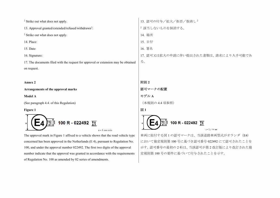
2 Strike out what does not apply.
13. Approval granted/extended/refused/withdrawn2:
2 Strike out what does not apply.
14. Place:
15. Date:
16. Signature:
17. The documents filed with the request for approval or extension may be obtained
on request.
13. 認可の付与/拡大/拒否/取消し 2
2 該当しないものを抹消する。
14. 場所
15. 日付
16. 署名
17. 認可又は拡大の申請に伴い提出された書類は、請求により入手可能であ
る。
Annex 2
Arrangements of the approval marks
附則 2
認可マークの配置
Model A
(See paragraph 4.4. of this Regulation)
Figure 1
The approval mark in Figure 1 affixed to a vehicle shows that the road vehicle type
concerned has been approved in the Netherlands (E 4), pursuant to Regulation No.
100, and under the approval number 022492. The first two digits of the approval
number indicate that the approval was granted in accordance with the requirements
of Regulation No. 100 as amended by 02 series of amendments.
モデル A
(本規則の 4.4 項参照)
図 1
車両に貼付する図 1 の認可マークは、当該道路車両型式がオランダ(E4)
において協定規則第 100 号に基づき認可番号 022492 にて認可されたことを
示す。認可番号の最初の 2 桁は、当該認可が第 2 改訂版により改訂された協
定規則第 100 号の要件に基づいて付与されたことを示す。
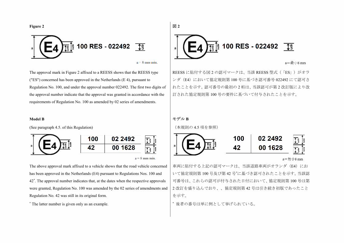
Figure 2
The approval mark in Figure 2 affixed to a REESS shows that the REESS type
("ES") concerned has been approved in the Netherlands (E 4), pursuant to
Regulation No. 100, and under the approval number 022492. The first two digits of
the approval number indicate that the approval was granted in accordance with the
requirements of Regulation No. 100 as amended by 02 series of amendments.
図 2
REESS に貼付する図 2 の認可マークは、当該 REESS 型式(「ES」)がオラ
ンダ(E4)において協定規則第 100 号に基づき認可番号 022492 にて認可さ
れたことを示す。認可番号の最初の 2 桁は、当該認可が第 2 改訂版により改
訂された協定規則第 100 号の要件に基づいて付与されたことを示す。
Model B
(See paragraph 4.5. of this Regulation)
The above approval mark affixed to a vehicle shows that the road vehicle concerned
has been approved in the Netherlands (E4) pursuant to Regulations Nos. 100 and
42*. The approval number indicates that, at the dates when the respective approvals
were granted, Regulation No. 100 was amended by the 02 series of amendments and
Regulation No. 42 was still in its original form.
* The latter number is given only as an example.
モデル B
(本規則の 4.5 項を参照)
車両に貼付する上記の認可マークは、当該道路車両がオランダ(E4)にお
いて協定規則第 100 号及び第 42 号*に基づき認可されたことを示す。当該認
可番号は、これらの認可が付与された日付において、協定規則第 100 号は第
2 改訂を盛り込んでおり、、協定規則第 42 号は引き続き初版であったこと
を示す。
* 後者の番号は単に例として挙げられている。
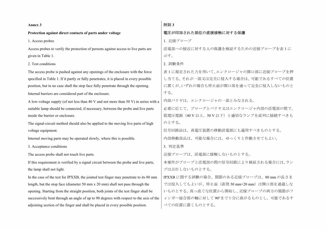
Annex 3
Protection against direct contacts of parts under voltage
附則 3
電圧が印加された部位の直接接触に対する保護
1. Access probes
Access probes to verify the protection of persons against access to live parts are
given in Table 1.
1. 近接プローブ
活電部への接近に対する人の保護を検証するための近接プローブを表 1 に
示す。
2. Test conditions
The access probe is pushed against any openings of the enclosure with the force
specified in Table 1. If it partly or fully penetrates, it is placed in every possible
position, but in no case shall the stop face fully penetrate through the opening.
Internal barriers are considered part of the enclosure.
A low-voltage supply (of not less than 40 V and not more than 50 V) in series with a
suitable lamp should be connected, if necessary, between the probe and live parts
inside the barrier or enclosure.
The signal-circuit method should also be applied to the moving live parts of high
voltage equipment.
Internal moving parts may be operated slowly, where this is possible.
2. 試験条件
表 1 に規定された力を用いて、エンクロージャの開口部に近接プローブを押
し当てる。それが一部又は完全に侵入する場合は、可能であるすべての位置
に置くが、いずれの場合も停止面が開口部を通って完全に侵入しないものと
する。
内部バリヤは、エンクロージャの一部とみなされる。
必要に応じて、プローブとバリヤ又はエンクロージャ内部の活電部の間で、
低電圧電源(40 V 以上、50 V 以下)と適切なランプを直列に接続すべきも
のとする。
信号回路法は、高電圧装置の移動活電部にも適用すべきものとする。
内部移動部品は、可能な場合には、ゆっくりと作動させてもよい。
3. Acceptance conditions
The access probe shall not touch live parts.
If this requirement is verified by a signal circuit between the probe and live parts,
the lamp shall not light.
In the case of the test for IPXXB, the jointed test finger may penetrate to its 80 mm
length, but the stop face (diameter 50 mm x 20 mm) shall not pass through the
opening. Starting from the straight position, both joints of the test finger shall be
successively bent through an angle of up to 90 degrees with respect to the axis of the
adjoining section of the finger and shall be placed in every possible position.
3. 判定基準
近接プローブは、活電部に接触しないものとする。
本要件がプローブと活電部の間の信号回路により検証される場合には、ラン
プは点灯しないものとする。
IPXXB に関する試験の場合、関節のある近接プローブは、80 mm の長さま
では侵入してもよいが、停止面(直径 50 mm×20 mm)は開口部を通過しな
いものとする。真っ直ぐな位置から開始し、近接プローブの両方の関節がフ
ィンガー接合部の軸に対して 90°まで十分に曲がるものとし、可能であるす
べての位置に置くものとする。
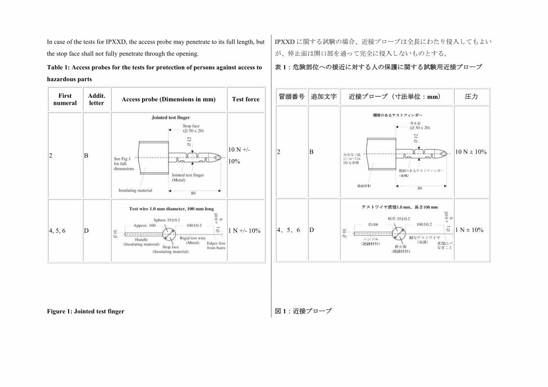
In case of the tests for IPXXD, the access probe may penetrate to its full length, but
the stop face shall not fully penetrate through the opening.
IPXXD に関する試験の場合、近接プローブは全長にわたり侵入してもよい
が、停止面は開口部を通って完全に侵入しないものとする。
Table 1: Access probes for the tests for protection of persons against access to
hazardous parts
First numeral
Addit. letter Access probe (Dimensions in mm) Test force
2 B
10 N +/-
10%
4, 5, 6 D 1 N +/- 10%
表 1:危険部位への接近に対する人の保護に関する試験用近接プローブ
冒頭番号 追加文字 近接プローブ(寸法単位:mm) 圧力
2 B
10 N ± 10%
4、5、6 D 1 N ± 10%
Figure 1: Jointed test finger 図 1:近接プローブ
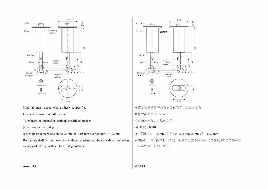
Material: metal, except where otherwise specified
Linear dimensions in millimeters
Tolerances on dimensions without specific tolerance:
(a) Nn angles: 0/-10 deg. ;
(b) On linear dimensions: up to 25 mm: 0/-0.05 mm over 25 mm: +/-0.2 mm
Both joints shall permit movement in the same plane and the same direction through
an angle of 90 deg. with a 0 to +10 deg. tolerance.
材質:別途指定がある場合を除き、金属とする
直線寸法の単位:mm
指定公差のない寸法の公差:
(a) 角度:0/-10°、
(b) 直線寸法:25 mm 以下:0/-0.05 mm 25 mm 超:±0.2 mm
両関節は、同一面において同一方向に公差 0°から+10°で角度 90°まで動かす
ことができるものとする。
Annex 4A 附則 4A
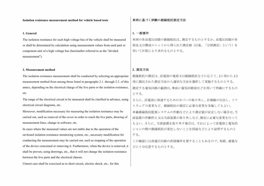
Isolation resistance measurement method for vehicle based tests 車両に基づく試験の絶縁抵抗測定方法
1. General
The isolation resistance for each high voltage bus of the vehicle shall be measured
or shall be determined by calculation using measurement values from each part or
component unit of a high voltage bus (hereinafter referred to as the "divided
measurement").
1. 一般要件
車両の各高電圧回路の絶縁抵抗は、測定するものとするか、高電圧回路の各
部品又は構成ユニットから得られた測定値(以後、「分割測定」という)を
用いて計算により求めるものとする。
2. Measurement method
The isolation resistance measurement shall be conducted by selecting an appropriate
measurement method from among those listed in paragraphs 2.1. through 2.2. of this
annex, depending on the electrical charge of the live parts or the isolation resistance,
etc.
The range of the electrical circuit to be measured shall be clarified in advance, using
electrical circuit diagrams, etc.
Moreover, modification necessary for measuring the isolation resistance may be
carried out, such as removal of the cover in order to reach the live parts, drawing of
measurement lines, change in software, etc.
In cases where the measured values are not stable due to the operation of the
on-board isolation resistance monitoring system, etc., necessary modification for
conducting the measurement may be carried out, such as stopping of the operation
of the device concerned or removing it. Furthermore, when the device is removed, it
shall be proven, using drawings, etc., that it will not change the isolation resistance
between the live parts and the electrical chassis.
Utmost care shall be exercised as to short circuit, electric shock, etc., for this
2. 測定方法
絶縁抵抗の測定は、活電部の電荷又は絶縁抵抗などに応じて、2.1 項から 2.2
項に掲出された測定方法から適切な方法を選択して実施するものとする。
測定する電気回路の範囲は、事前に電気回路図などを用いて明確にするもの
とする。
さらに、活電部に到達するためのカバーの取り外し、計測線の引出し、ソフ
トウェアの変更など、絶縁抵抗の測定に必要な変更を実施してもよい。
車載絶縁抵抗監視システムの作動などにより測定値が安定しない場合は、当
該装置の作動停止又は当該装置の取り外しなど、測定に必要な変更を行って
もよい。さらに、当該装置を取り外す場合は、それによって活電部と電気的
シャシの間の絶縁抵抗が変化しないことを図面などにより証明するものと
する。
この確認には高電圧回路の直接操作を要することもあるので、短絡、感電な
どに十分注意するものとする。
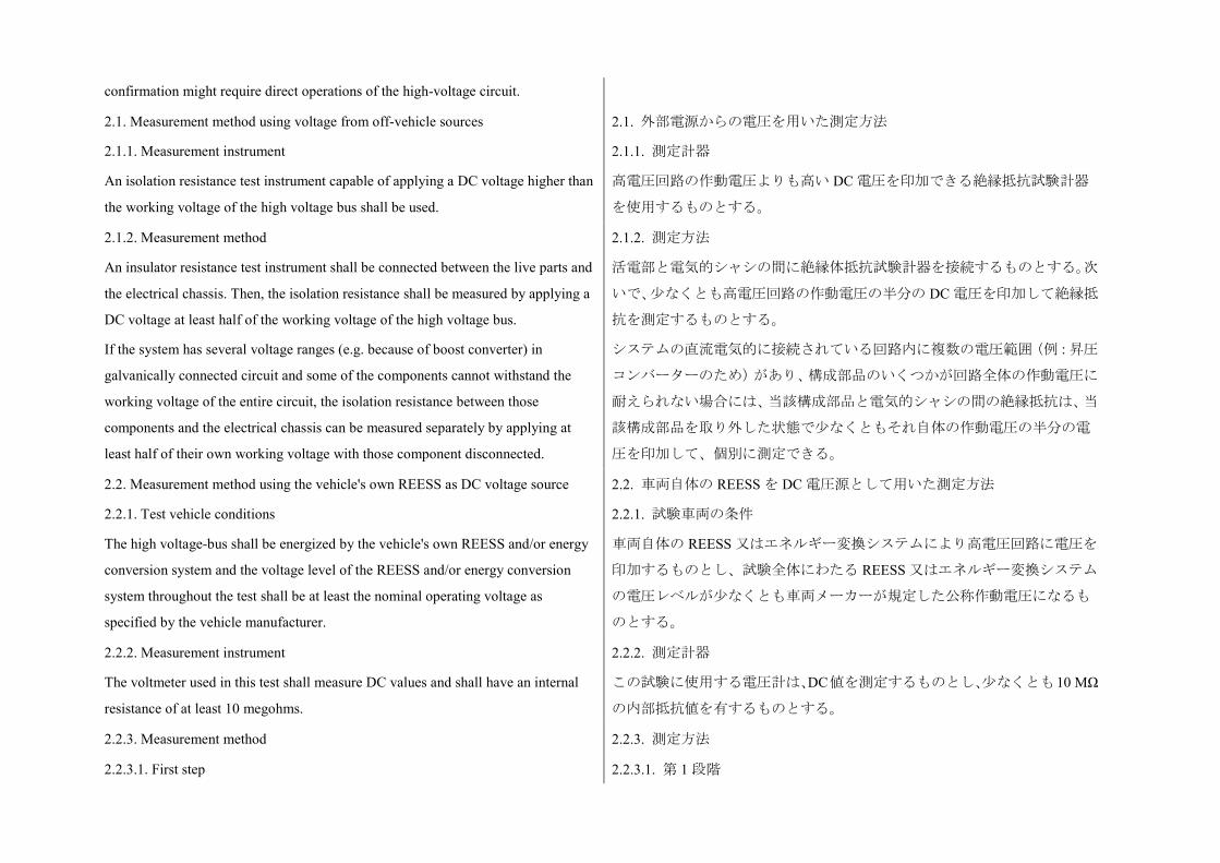
confirmation might require direct operations of the high-voltage circuit.
2.1. Measurement method using voltage from off-vehicle sources
2.1.1. Measurement instrument
An isolation resistance test instrument capable of applying a DC voltage higher than
the working voltage of the high voltage bus shall be used.
2.1. 外部電源からの電圧を用いた測定方法
2.1.1. 測定計器
高電圧回路の作動電圧よりも高い DC 電圧を印加できる絶縁抵抗試験計器
を使用するものとする。
2.1.2. Measurement method
An insulator resistance test instrument shall be connected between the live parts and
the electrical chassis. Then, the isolation resistance shall be measured by applying a
DC voltage at least half of the working voltage of the high voltage bus.
If the system has several voltage ranges (e.g. because of boost converter) in
galvanically connected circuit and some of the components cannot withstand the
working voltage of the entire circuit, the isolation resistance between those
components and the electrical chassis can be measured separately by applying at
least half of their own working voltage with those component disconnected.
2.1.2. 測定方法
活電部と電気的シャシの間に絶縁体抵抗試験計器を接続するものとする。次
いで、少なくとも高電圧回路の作動電圧の半分の DC 電圧を印加して絶縁抵
抗を測定するものとする。
システムの直流電気的に接続されている回路内に複数の電圧範囲(例:昇圧
コンバーターのため)があり、構成部品のいくつかが回路全体の作動電圧に
耐えられない場合には、当該構成部品と電気的シャシの間の絶縁抵抗は、当
該構成部品を取り外した状態で少なくともそれ自体の作動電圧の半分の電
圧を印加して、個別に測定できる。
2.2. Measurement method using the vehicle's own REESS as DC voltage source
2.2.1. Test vehicle conditions
The high voltage-bus shall be energized by the vehicle's own REESS and/or energy
conversion system and the voltage level of the REESS and/or energy conversion
system throughout the test shall be at least the nominal operating voltage as
specified by the vehicle manufacturer.
2.2. 車両自体の REESS を DC 電圧源として用いた測定方法
2.2.1. 試験車両の条件
車両自体の REESS 又はエネルギー変換システムにより高電圧回路に電圧を
印加するものとし、試験全体にわたる REESS 又はエネルギー変換システム
の電圧レベルが少なくとも車両メーカーが規定した公称作動電圧になるも
のとする。
2.2.2. Measurement instrument
The voltmeter used in this test shall measure DC values and shall have an internal
resistance of at least 10 megohms.
2.2.2. 測定計器
この試験に使用する電圧計は、DC値を測定するものとし、少なくとも10 MΩ
の内部抵抗値を有するものとする。
2.2.3. Measurement method 2.2.3. 測定方法
2.2.3.1. First step 2.2.3.1. 第 1 段階
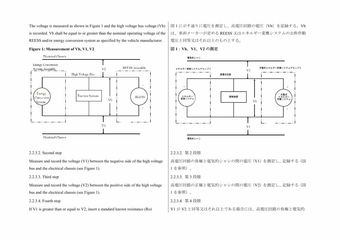
The voltage is measured as shown in Figure 1 and the high voltage bus voltage (Vb)
is recorded. Vb shall be equal to or greater than the nominal operating voltage of the
REESS and/or energy conversion system as specified by the vehicle manufacturer.
図 1 に示す通りに電圧を測定し、高電圧回路の電圧(Vb)を記録する。Vb
は、車両メーカーが定める REESS 又はエネルギー変換システムの公称作動
電圧と同等又はそれ以上のものとする。
Figure 1: Measurement of Vb, V1, V2
図 1:Vb、V1、V2 の測定
2.2.3.2. Second step
Measure and record the voltage (V1) between the negative side of the high voltage
bus and the electrical chassis (see Figure 1).
2.2.3.2. 第 2 段階
高電圧回路の負極と電気的シャシの間の電圧(V1)を測定し、記録する(図
1 を参照)。
2.2.3.3. Third step
Measure and record the voltage (V2) between the positive side of the high voltage
bus and the electrical chassis (see Figure 1).
2.2.3.3. 第 3 段階
高電圧回路の正極と電気的シャシの間の電圧(V2)を測定し、記録する(図
1 を参照)。
2.2.3.4. Fourth step
If V1 is greater than or equal to V2, insert a standard known resistance (Ro)
2.2.3.4. 第 4 段階
V1 が V2 と同等又はそれ以上である場合には、高電圧回路の負極と電気的
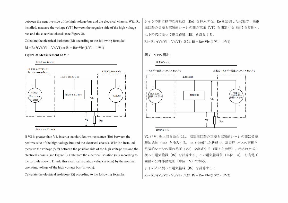
between the negative side of the high voltage bus and the electrical chassis. With Ro
installed, measure the voltage (V1') between the negative side of the high voltage
bus and the electrical chassis (see Figure 2).
Calculate the electrical isolation (Ri) according to the following formula:
Ri = Ro*(Vb/V1' - Vb/V1) or Ri = Ro*Vb*(1/V1' - 1/V1)
シャシの間に標準既知抵抗(Ro)を挿入する。Ro を装備した状態で、高電
圧回路の負極と電気的シャシの間の電圧(V1')を測定する(図 2 を参照)。
以下の式に従って電気絶縁(Ri)を計算する。
Ri = Ro×(Vb/V1' - Vb/V1) 又は Ri = Ro×Vb×(1/V1' - 1/V1)
Figure 2: Measurement of V1'
図 2:V1'の測定
If V2 is greater than V1, insert a standard known resistance (Ro) between the
positive side of the high voltage bus and the electrical chassis. With Ro installed,
measure the voltage (V2') between the positive side of the high voltage bus and the
electrical chassis (see Figure 3). Calculate the electrical isolation (Ri) according to
the formula shown. Divide this electrical isolation value (in ohm) by the nominal
operating voltage of the high voltage bus (in volts).
Calculate the electrical isolation (Ri) according to the following formula:
V2 が V1 を上回る場合には、高電圧回路の正極と電気的シャシの間に標準
既知抵抗(Ro)を挿入する。Ro を装備した状態で、高電圧 バスの正極と
電気的シャシの間の電圧(V2')を測定する(図 3 を参照)。示された式に
従って電気絶縁(Ri)を計算する。この電気絶縁値(単位:Ω) を高電圧
回路の公称作動電圧(単位:V)で割る。
以下の式に従って電気絶縁(Ri)を計算する:
Ri = Ro×(Vb/V2' - Vb/V2) 又は Ri = Ro×Vb×(1/V2' - 1/V2)
Ri = Ro*(Vb/V2' - Vb/V2) or Ri = Ro*Vb*(1/V2' - 1/V2)
Figure 3: Measurement of V2'
図 3:V2'の測定
2.2.3.5. Fifth step
The electrical isolation value Ri (in ohm) divided by the working voltage of the high
voltage bus (in volts) results in the isolation resistance (in ohm/V).
Note: The standard known resistance Ro (in ohm) should be the value of the
minimum required isolation resistance (in ohm/V) multiplied by the working
voltage of the vehicle plus/minus 20 per cent (in volts). Ro is not required to be
precisely this value since the equations are valid for any Ro; however, a Ro value in
this range should provide good resolution for the voltage measurements.
2.2.3.5. 第 5 段階
電気絶縁値 Ri(単位:Ω)を高電圧回路の作動電圧(単位:V)で割った結
果が絶縁抵抗(単位:Ω/V)である。
注記:標準既知抵抗 Ro(単位:Ω)は、絶縁抵抗要件の最小値(単位:Ω/V)
を車両の作動電圧±20%(単位:V)で乗じた値であるべきものとする。当
該方程式はいずれの Ro にも有効であるため、Ro は、厳密にこの値である
必要はない。しかしながら、この範囲の Ro 値が電圧測定に関して良好な分
解能を提供するはずである。
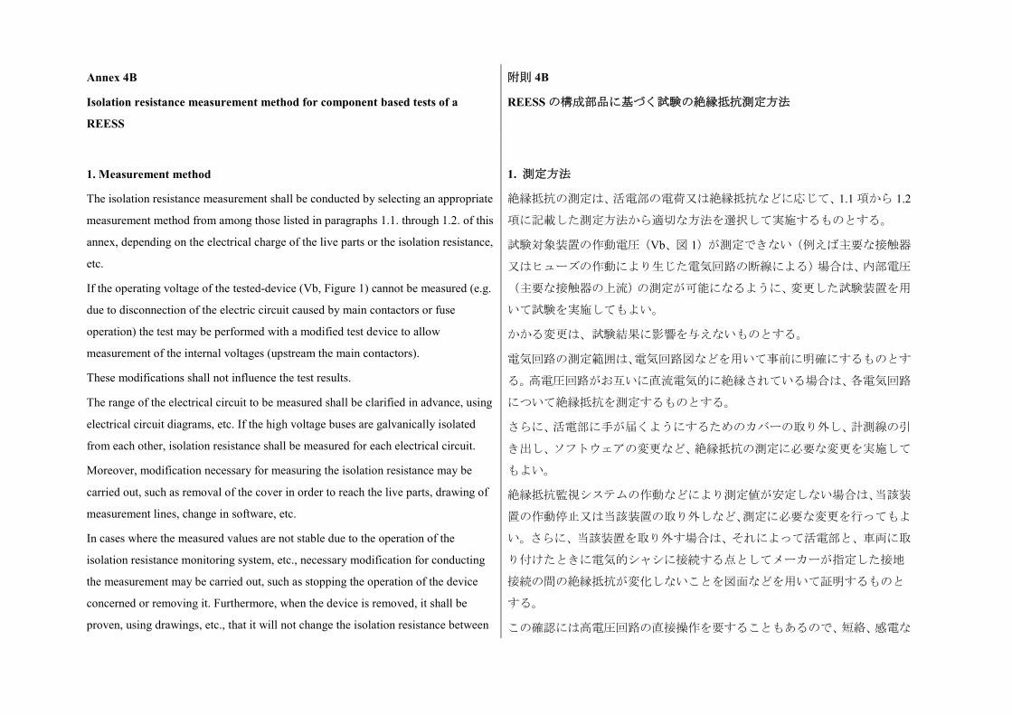
Annex 4B
Isolation resistance measurement method for component based tests of a
REESS
附則 4B
REESS の構成部品に基づく試験の絶縁抵抗測定方法
1. Measurement method
The isolation resistance measurement shall be conducted by selecting an appropriate
measurement method from among those listed in paragraphs 1.1. through 1.2. of this
annex, depending on the electrical charge of the live parts or the isolation resistance,
etc.
If the operating voltage of the tested-device (Vb, Figure 1) cannot be measured (e.g.
due to disconnection of the electric circuit caused by main contactors or fuse
operation) the test may be performed with a modified test device to allow
measurement of the internal voltages (upstream the main contactors).
These modifications shall not influence the test results.
The range of the electrical circuit to be measured shall be clarified in advance, using
electrical circuit diagrams, etc. If the high voltage buses are galvanically isolated
from each other, isolation resistance shall be measured for each electrical circuit.
Moreover, modification necessary for measuring the isolation resistance may be
carried out, such as removal of the cover in order to reach the live parts, drawing of
measurement lines, change in software, etc.
In cases where the measured values are not stable due to the operation of the
isolation resistance monitoring system, etc., necessary modification for conducting
the measurement may be carried out, such as stopping the operation of the device
concerned or removing it. Furthermore, when the device is removed, it shall be
proven, using drawings, etc., that it will not change the isolation resistance between
1. 測定方法
絶縁抵抗の測定は、活電部の電荷又は絶縁抵抗などに応じて、1.1 項から 1.2
項に記載した測定方法から適切な方法を選択して実施するものとする。
試験対象装置の作動電圧(Vb、図 1)が測定できない(例えば主要な接触器
又はヒューズの作動により生じた電気回路の断線による)場合は、内部電圧
(主要な接触器の上流)の測定が可能になるように、変更した試験装置を用
いて試験を実施してもよい。
かかる変更は、試験結果に影響を与えないものとする。
電気回路の測定範囲は、電気回路図などを用いて事前に明確にするものとす
る。高電圧回路がお互いに直流電気的に絶縁されている場合は、各電気回路
について絶縁抵抗を測定するものとする。
さらに、活電部に手が届くようにするためのカバーの取り外し、計測線の引
き出し、ソフトウェアの変更など、絶縁抵抗の測定に必要な変更を実施して
もよい。
絶縁抵抗監視システムの作動などにより測定値が安定しない場合は、当該装
置の作動停止又は当該装置の取り外しなど、測定に必要な変更を行ってもよ
い。さらに、当該装置を取り外す場合は、それによって活電部と、車両に取
り付けたときに電気的シャシに接続する点としてメーカーが指定した接地
接続の間の絶縁抵抗が変化しないことを図面などを用いて証明するものと
する。
この確認には高電圧回路の直接操作を要することもあるので、短絡、感電な
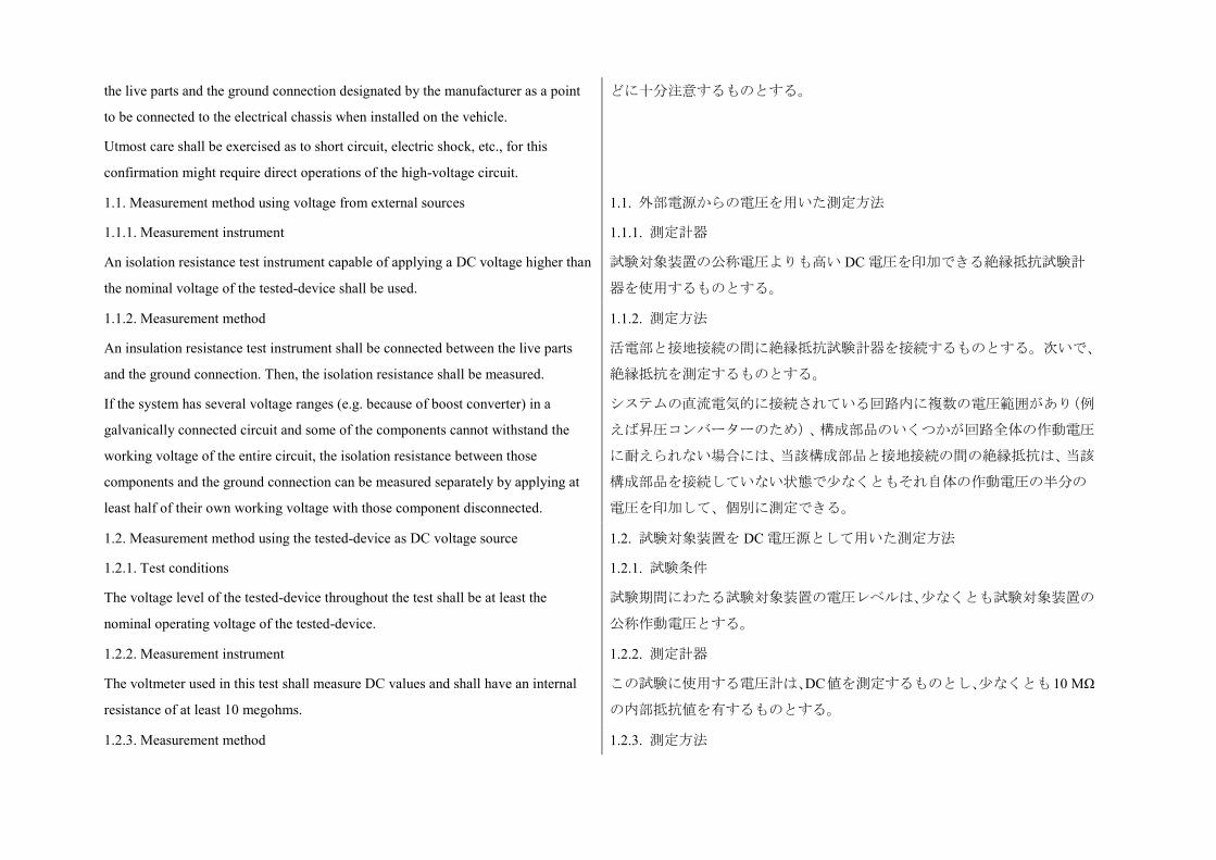
the live parts and the ground connection designated by the manufacturer as a point
to be connected to the electrical chassis when installed on the vehicle.
Utmost care shall be exercised as to short circuit, electric shock, etc., for this
confirmation might require direct operations of the high-voltage circuit.
どに十分注意するものとする。
1.1. Measurement method using voltage from external sources
1.1.1. Measurement instrument
An isolation resistance test instrument capable of applying a DC voltage higher than
the nominal voltage of the tested-device shall be used.
1.1. 外部電源からの電圧を用いた測定方法
1.1.1. 測定計器
試験対象装置の公称電圧よりも高い DC 電圧を印加できる絶縁抵抗試験計
器を使用するものとする。
1.1.2. Measurement method
An insulation resistance test instrument shall be connected between the live parts
and the ground connection. Then, the isolation resistance shall be measured.
If the system has several voltage ranges (e.g. because of boost converter) in a
galvanically connected circuit and some of the components cannot withstand the
working voltage of the entire circuit, the isolation resistance between those
components and the ground connection can be measured separately by applying at
least half of their own working voltage with those component disconnected.
1.1.2. 測定方法
活電部と接地接続の間に絶縁抵抗試験計器を接続するものとする。次いで、
絶縁抵抗を測定するものとする。
システムの直流電気的に接続されている回路内に複数の電圧範囲があり(例
えば昇圧コンバーターのため)、構成部品のいくつかが回路全体の作動電圧
に耐えられない場合には、当該構成部品と接地接続の間の絶縁抵抗は、当該
構成部品を接続していない状態で少なくともそれ自体の作動電圧の半分の
電圧を印加して、個別に測定できる。
1.2. Measurement method using the tested-device as DC voltage source
1.2.1. Test conditions
The voltage level of the tested-device throughout the test shall be at least the
nominal operating voltage of the tested-device.
1.2. 試験対象装置を DC 電圧源として用いた測定方法
1.2.1. 試験条件
試験期間にわたる試験対象装置の電圧レベルは、少なくとも試験対象装置の
公称作動電圧とする。
1.2.2. Measurement instrument
The voltmeter used in this test shall measure DC values and shall have an internal
resistance of at least 10 megohms.
1.2.2. 測定計器
この試験に使用する電圧計は、DC値を測定するものとし、少なくとも10 MΩ
の内部抵抗値を有するものとする。
1.2.3. Measurement method 1.2.3. 測定方法
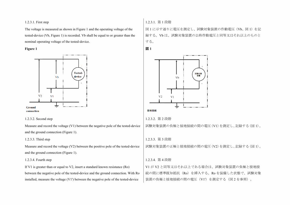
1.2.3.1. First step
The voltage is measured as shown in Figure 1 and the operating voltage of the
tested-device (Vb, Figure 1) is recorded. Vb shall be equal to or greater than the
nominal operating voltage of the tested-device.
Figure 1
1.2.3.1. 第 1 段階
図 1 に示す通りに電圧を測定し、試験対象装置の作動電圧(Vb、図 1)を記
録する。Vb は、試験対象装置の公称作動電圧と同等又はそれ以上のものと
する。
図 1
1.2.3.2. Second step
Measure and record the voltage (V1) between the negative pole of the tested-device
and the ground connection (Figure 1).
1.2.3.2. 第 2 段階
試験対象装置の負極と接地接続の間の電圧(V1)を測定し、記録する(図 1)。
1.2.3.3. Third step
Measure and record the voltage (V2) between the positive pole of the tested-device
and the ground connection (Figure 1).
1.2.3.3. 第 3 段階
試験対象装置の正極と接地接続の間の電圧(V2)を測定し、記録する(図 1)。
1.2.3.4. Fourth step
If V1 is greater than or equal to V2, insert a standard known resistance (Ro)
between the negative pole of the tested-device and the ground connection. With Ro
installed, measure the voltage (V1') between the negative pole of the tested-device
1.2.3.4. 第 4 段階
V1 が V2 と同等又はそれ以上である場合は、試験対象装置の負極と接地接
続の間に標準既知抵抗(Ro)を挿入する。Ro を装備した状態で、試験対象
装置の負極と接地接続の間の電圧(V1')を測定する(図 2 を参照)。
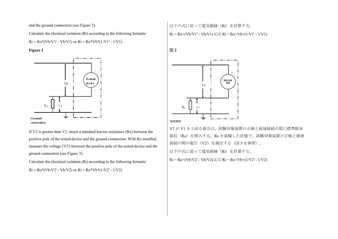
and the ground connection (see Figure 2).
Calculate the electrical isolation (Ri) according to the following formula:
Ri = Ro*(Vb/V1' - Vb/V1) or Ri = Ro*Vb*(1/V1' - 1/V1)
以下の式に従って電気絶縁(Ri)を計算する。
Ri = Ro×(Vb/V1' - Vb/V1)又は Ri = Ro×Vb×(1/V1' - 1/V1)
Figure 2
If V2 is greater than V1, insert a standard known resistance (Ro) between the
positive pole of the tested-device and the ground connection. With Ro installed,
measure the voltage (V2') between the positive pole of the tested-device and the
ground connection (see Figure 3).
Calculate the electrical isolation (Ri) according to the following formula:
Ri = Ro*(Vb/V2' - Vb/V2) or Ri = Ro*Vb*(1/V2' - 1/V2)
図 2
V2 が V1 を上回る場合は、試験対象装置の正極と接地接続の間に標準既知
抵抗(Ro)を挿入する。Ro を装備した状態で、試験対象装置の正極と接地
接続の間の電圧(V2')を測定する(図 3 を参照)。
以下の式に従って電気絶縁(Ri)を計算する。
Ri = Ro×(Vb/V2' - Vb/V2)又は Ri = Ro×Vb×(1/V2' - 1/V2)
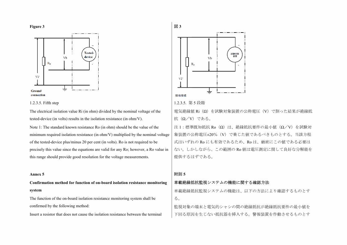
Figure 3
図 3
1.2.3.5. Fifth step
The electrical isolation value Ri (in ohm) divided by the nominal voltage of the
tested-device (in volts) results in the isolation resistance (in ohm/V).
Note 1: The standard known resistance Ro (in ohm) should be the value of the
minimum required isolation resistance (in ohm/V) multiplied by the nominal voltage
of the tested-device plus/minus 20 per cent (in volts). Ro is not required to be
precisely this value since the equations are valid for any Ro; however, a Ro value in
this range should provide good resolution for the voltage measurements.
1.2.3.5. 第 5 段階
電気絶縁値 Ri(Ω)を試験対象装置の公称電圧(V)で割った結果が絶縁抵
抗(Ω/V)である。
注 1:標準既知抵抗 Ro(Ω)は、絶縁抵抗要件の最小値(Ω/V)を試験対
象装置の公称電圧±20%(V)で乗じた値であるべきものとする。当該方程
式はいずれの Ro にも有効であるため、Ro は、厳密にこの値である必要は
ない。しかしながら、この範囲の Ro 値は電圧測定に関して良好な分解能を
提供するはずである。
Annex 5
Confirmation method for function of on-board isolation resistance monitoring
system
The function of the on-board isolation resistance monitoring system shall be
confirmed by the following method:
Insert a resistor that does not cause the isolation resistance between the terminal
附則 5
車載絶縁抵抗監視システムの機能に関する確認方法
車載絶縁抵抗監視システムの機能は、以下の方法により確認するものとす
る。
監視対象の端末と電気的シャシの間の絶縁抵抗が絶縁抵抗要件の最小値を
下回る原因を生じない抵抗器を挿入する。警報装置を作動させるものとす
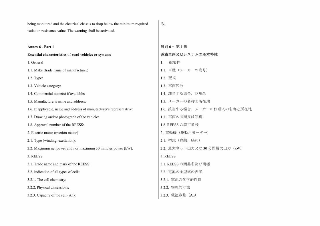
being monitored and the electrical chassis to drop below the minimum required
isolation resistance value. The warning shall be activated.
る。
Annex 6 - Part 1
Essential characteristics of road vehicles or systems
附則 6 − 第 1 部
道路車両又はシステムの基本特性
1. General
1.1. Make (trade name of manufacturer):
1.2. Type:
1.3. Vehicle category:
1.4. Commercial name(s) if available:
1.5. Manufacturer's name and address:
1.6. If applicable, name and address of manufacturer's representative:
1.7. Drawing and/or photograph of the vehicle:
1.8. Approval number of the REESS:
1. 一般要件
1.1. 車種(メーカーの商号)
1.2. 型式
1.3. 車両区分
1.4. 該当する場合、商用名
1.5. メーカーの名称と所在地
1.6. 該当する場合、メーカーの代理人の名称と所在地
1.7. 車両の図面又は写真
1.8. REESS の認可番号
2. Electric motor (traction motor)
2.1. Type (winding, excitation):
2.2. Maximum net power and / or maximum 30 minutes power (kW):
2. 電動機(駆動用モーター)
2.1. 型式(巻線、励起)
2.2. 最大ネット出力又は 30 分間最大出力(kW)
3. REESS
3.1. Trade name and mark of the REESS:
3.2. Indication of all types of cells:
3.2.1. The cell chemistry:
3.2.2. Physical dimensions:
3.2.3. Capacity of the cell (Ah):
3. REESS
3.1. REESS の商品名及び商標
3.2. 電池の全型式の表示
3.2.1. 電池の化学的性質
3.2.2. 物理的寸法
3.2.3. 電池容量(Ah)
3.3. Description or drawing(s) or picture(s) of the REESS explaining:
3.3.1. Structure:
3.3.2. Configuration (number of cells, mode of connection, etc.):
3.3.3. Dimensions:
3.3.4. Casing (construction, materials and physical dimensions):
3.4. Electrical specification:
3.4.1. Nominal voltage (V):
3.4.2. Working voltage (V):
3.4.3. Capacity (Ah):
3.4.4. Maximum current (A):
3.5. Gas combination rate (in per cent):
3.6. Description or drawing(s) or picture(s) of the installation of the REESS in the
vehicle:
3.3. 以下を説明する REESS の説明又は図面又は写真
3.3.1. 構造
3.3.2. コンフィギュレーション(電池の数、接続モードなど)
3.3.3. 寸法
3.3.4. ケーシング(構造、材質及び物理的寸法)
3.4. 電気仕様
3.4.1. 公称電圧(V)
3.4.2. 作動電圧(V)
3.4.3. 容量(Ah)
3.4.4. 最大電流(A)
3.5. ガス結合率(%)
3.6. REESS の車両への取り付けの説明又は図面又は写真
3.6.1. Physical support:
3.7. Type of thermal management
3.8. Electronic control:
3.6.1. 物理的サポート
3.7. 熱管理の種類
3.8. 電子制御
4. Fuel Cell (if any)
4.1. Trade name and mark of the fuel cell:
4.2. Types of fuel cell:
4.3. Nominal voltage (V):
4.4. Number of cells:
4.5. Type of cooling system (if any):
4.6. Max Power(kW):
4. 燃料電池(ある場合)
4.1. 燃料電池の商品名と商標
4.2. 燃料電池の型式
4.3. 公称電圧(V)
4.4. 電池の数
4.5. 冷却システムの型式(ある場合)
4.6. 最大出力(kW)
5. Fuse and/or circuit breaker
5.1. Type:
5.2. Diagram showing the functional range:
5. ヒューズ又は回路遮断器
5.1. 型式
5.2. 機能範囲を示す図面
6. Power wiring harness
6.1. Type:
6. 電源配線ハーネス
6.1. 型式
7. Protection against Electric Shock
7.1. Description of the protection concept:
7. 感電に対する保護
7.1. 保護概念の説明
8. Additional data
8.1. Brief description of the power circuit components installation or
drawings/pictures showing the location of the power circuit components installation:
8.2. Schematic diagram of all electrical functions included in power circuit:
8.3. Working voltage (V):
8. 追加データ
8.1. 電源回路の構成部品の取り付けに関する概要説明又は電源回路の構成
部品の取り付け位置を示す図面/画像
8.2. 電源回路に含まれるすべての電気機能の回路図
8.3. 作動電圧(V)
Annex 6 - Part 2
Essential characteristics of REESS
附則 6 − 第 2 部
REESS の基本特性
1. REESS
1.1. Trade name and mark of the REESS:
1.2. Indication of all types of cells:
1.2.1. The cell chemistry:
1.2.2. Physical dimensions:
1.2.3. Capacity of the cell (Ah):
1.3. Description or drawing(s) or picture(s) of the REESS explaining
1.3.1. Structure:
1. REESS
1.1. REESS の商品名及び商標
1.2. 電池の全型式の表示
1.2.1. 電池の化学的性質
1.2.2. 物理的寸法
1.2.3. 電池容量(Ah)
1.3. 以下を説明する REESS の説明又は図面又は写真
1.3.1. 構造
1.3.2. Configuration (number of cells, mode of connection, etc.):
1.3.3. Dimensions:
1.3.4. Casing (construction, materials and physical dimensions):
1.4. Electrical specification
1.4.1. Nominal voltage (V):
1.4.2. Working voltage (V):
1.4.3. Capacity (Ah):
1.4.4. Maximum current (A):
1.5. Gas combination rate (in percentage):
1.6. Description or drawing(s) or picture(s) of the installation of the REESS in the
vehicle:
1.3.2. コンフィギュレーション(電池の数、接続モードなど)
1.3.3. 寸法
1.3.4. ケーシング(構造、材質及び物理的寸法)
1.4. 電気仕様
1.4.1. 公称電圧(V)
1.4.2. 作動電圧(V)
1.4.3. 容量(Ah)
1.4.4. 最大電流(A)
1.5. ガス結合率(%)
1.6. REESS の車両への取り付けの説明又は図面又は写真
1.6.1. Physical support:
1.7. Type of thermal management:
1.8. Electronic control:
1.9. Category of vehicles on which the REESS can be installed:
1.6.1. 物理的サポート
1.7. 熱管理の種類
1.8. 電子制御
1.9. REESS の取り付けが可能な車両区分
Annex 6 - Part 3
Essential characteristics of road vehicles or systems with chassis connected to
electrical circuits
附則 6 − 第 3 部
電気回路接続シャシを備えた道路車両またはシステムの本質的な特性
1. General
1.1. Make (trade name of manufacturer):
1.2. Type:
1.3. Vehicle category:
1.4. Commercial name(s) if available:
1. 一般情報
1.1. 車種(メーカーの商号):
1.2. 型式:
1.3.車両カテゴリー:
1.4.該当する場合、商用名:
1.5. Manufacturer's name and address:
1.6. If applicable, name and address of manufacturer's representative:
1.7.Drawing and/or photograph of the vehicle:
1.8.Approval number of the REESS:
1.5.メーカーの名称と所在地:
1.6. 該当する場合、メーカーの代理人の名称と所在地:
1.7.車両の図面および/または写真:
1.8.REESS の認可番号:
2. REESS
2.1. Trade name and mark of the REESS:
2.2. The cell chemistry:
2.3. Electrical specification:
2.3.1. Nominal voltage (V):
2.3.2. Capacity (Ah):
2.3.3. Maximum current (A):
2.4. Gas combination rate (in per cent):
2.5. Description or drawing(s) or picture(s) of the installation of the REESS in the
vehicle:
2. REESS
2.1. REESS の商品名および商標:
2.2. 電池の化学的性質:
2.3. 電気仕様:
2.3.1. 公称電圧(V):
2.3.2. 容量(Ah):
2.3.3. 最大電流(A):
2.4. ガス結合率(%):
2.5. REESS の車両への取り付けの説明または図面または画像:
3. Additional data
3.1. Working voltage (V) AC circuit:
3.2. Working voltage (V) DC circuit:
3. 追加データ
3.1. AC 回路の作動電圧(V):
3.2. DC 回路の作動電圧(V):
Annex 7
Determination of hydrogen emissions during the charge procedures of the
REESS
附則 7
REESS の充電手順における水素エミッションの測定
1. Introduction
This annex describes the procedure for the determination of hydrogen emissions
during the charge procedures of the REESS of all road vehicles, according to
1. 前文
本附則は、本規則の 5.4 項に従った、すべての道路車両の REESS の充電手
順における水素エミッションの測定に関する手順を記載する。
paragraph 5.4. of this Regulation.
2. Description of test
The hydrogen emission test (Figure 7.1 of the present annex) is conducted in order
to determine hydrogen emissions during the charge procedures of the REESS with
the charger. The test consists in the following steps:
(a) Vehicle/REESS preparation;
(b) Discharge of theREESS;
(c) Determination of hydrogen emissions during a normal charge;
(d) Determination of hydrogen emissions during a charge carried out with the
charger failure.
2. 試験の説明
水素エミッション試験(本附則の図 7.1)は、充電器を用いた REESS の充電
手順における水素エミッションを測定するために実施されるものである。当
該試験は、以下の段階から成る。
(a) 車両/REESS の準備、
(b) REESS の放電、
(c) 正常充電中の水素エミッションの測定、
(d) 充電器の故障を伴って実施する充電中の水素エミッションの測定。
3. Tests
3.1. Vehicle based test
3.1.1. The vehicle shall be in good mechanical condition and have been driven at
least 300 km during seven days before the test. The vehicle shall be equipped with
the REESS subject to the test of hydrogen emissions, over this period.
3. 試験
3.1. 車両に基づく試験
3.1.1. 車両は、良好な機械的状態にあり、試験前の 7日間に少なくとも 300km
走行しているものとする。当該車両にはこの期間、水素エミッション試験の
対象の REESS が装備されているものとする。
3.1.2. If the REESS is used at a temperature above the ambient temperature, the
operator shall follow the manufacturer's procedure in order to keep the REESS
temperature in normal functioning range.
The manufacturer's representative shall be able to certify that the temperature
conditioning system of the REESS is neither damaged nor presenting a capacity
defect.
3.1.2. REESS が周囲温度を超える温度で使用される場合、オペレータは、
REESS の温度を通常の機能範囲内に維持するためのメーカーの手順に従う
ものとする。
メーカーの代理人は、REESS の温度調整システムに損傷がなく、能力の欠
陥も呈していないことを証明できるものとする。
3.2. Component based test 3.2. 構成部品に基づく試験
3.2.1. The REESS shall be in good mechanical condition and have been subject to
minimum of 5 standard cycles (as specified in Annex 8, Appendix 1).
3.2.1. REESS は良好な機械的状態にあり、標準サイクルを最低 5 回実施して
いるものとする(附則 8 の付録 1 に規定した通り)。
3.2.2. If the REESS is used at a temperature above the ambient temperature, the
operator shall follow the manufacturer's procedure in order to keep the REESS
temperature in its normal functioning range.
The manufacturer's representative shall be able to certify that the temperature
conditioning system of the REESS is neither damaged nor presenting a capacity
defect
3.2.2. REESS が周囲温度を超える温度で使用される場合、オペレータは、
REESS の温度を通常の機能範囲内に維持するためのメーカーの手順に従う
ものとする。
メーカーの代理人は、REESS の温度調整システムに損傷がなく、能力の欠
陥も呈していないことを証明できるものとする。
Figure 7.1: Determination of hydrogen emissions during the charge procedures
of the REESS
図 7.1.:REESS の充電手順における水素エミッションの測定
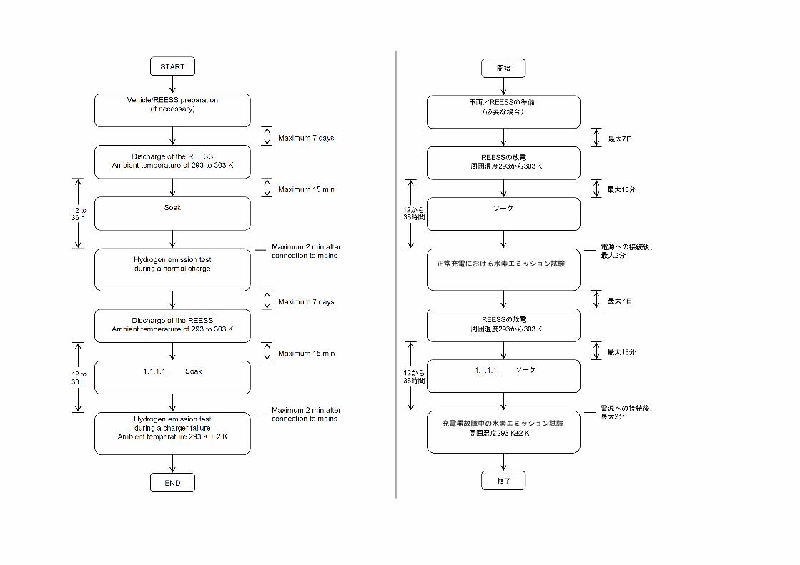
正常充電における水素エミッション試験
充電器故障中の水素エミッション試験
4. Test equipment for hydrogen emission test
4.1. Chassis dynamometer
The chassis dynamometer shall meet the requirements of the 06 series of
amendments to Regulation No. 83.
4. 水素エミッション試験の試験機器
4.1. シャシダイナモメーター
シャシダイナモメーターは、協定規則第 83 号の第 6 改訂版の要件を満たす
ものとする。
4.2. Hydrogen emission measurement enclosure
The hydrogen emission measurement enclosure shall be a gas-tight measuring
chamber able to contain the vehicle/REESS under test. The vehicle/REESS shall be
accessible from all sides and the enclosure when sealed shall be gas-tight in
accordance with Appendix 1 to this annex. The inner surface of the enclosure shall
be impermeable and non-reactive to hydrogen. The temperature conditioning system
shall be capable of controlling the internal enclosure air temperature to follow the
prescribed temperature throughout the test, with an average tolerance of +/-2 K over
the duration of the test.
To accommodate the volume changes due to enclosure hydrogen emissions, either a
variable-volume or another test equipment may be used. The variable-volume
enclosure expands and contracts in response to the hydrogen emissions in the
enclosure. Two potential means of accommodating the internal volume changes are
movable panels, or a bellows design, in which impermeable bags inside the
enclosure expand and contract in response to internal pressure changes by
exchanging air from outside the enclosure. Any design for volume accommodation
shall maintain the integrity of the enclosure as specified in Appendix 1 to this annex.
Any method of volume accommodation shall limit the differential between the
enclosure internal pressure and the barometric pressure to a maximum value of
+/-5hPa.
4.2. 水素エミッション測定用エンクロージャ
水 素エミッション測定用エンクロージャは、試験中の車両/REESS を収容
することが可能なガス気密性のある測定用チャンバとする。車両/REESS
は、すべての方向から接近することができるものとし、エンクロージャは、
密閉状態の時、本附則の付録 1 に従ったガス気密性を有するものとする。エ
ンクロージャの内側表面は、不浸透性を有し、水素に反応しないものとする。
温度調整システムは、試験全体を通して規定温度を守るために、試験期間に
わたる平均公差を±2 K としてエンクロージャ内部の空気温度を制御するこ
とができるものとする。
エンクロージャの水素エミッションによる容積の変化に対応するために、可
変容積又は他の試験機器のいずれかを使用してもよい。可変容積エンクロー
ジャは、エンクロージャ内の水素エミッション量に応じて拡張及び収縮す
る。内部容積の変化に対応するための 2 つの手段として、可動パネル、又は、
エンクロージャの外と空気を交換することにより内圧の変化に応じてエン
クロージャ内の不浸透性バッグが拡張及び収縮する蛇腹設計が考えられる。
いずれの容積調節設計も、本附則の付録 1 に規定されたエンクロージャの完
全性を維持するものとする。
いずれの容積調節方法も、エンクロージャ内圧と気圧の差を最大値±5 hPa
に制限するものとする。
エンクロージャは、固定容積になるようラッチを掛けることができるものと
The enclosure shall be capable of latching to a fixed volume. A variable volume
enclosure shall be capable of accommodating a change from its "nominal volume"
(see Annex 7, Appendix 1, paragraph 2.1.1.), taking into account hydrogen
emissions during testing.
する。可変容積エンクロージャは、試験中の水素エミッション量を考慮に入
れて、「公称容積」(附則 7 の付録 1、2.1.1 項を参照)からの変化に対応す
ることができるものとする。
4.3. Analytical systems
4.3.1. Hydrogen analyser
4.3.1.1. The atmosphere within the chamber is monitored using a hydrogen analyser
(electrochemical detector type) or a chromatograph with thermal conductivity
detection. Sample gas shall be drawn from the mid-point of one side-wall or roof of
the chamber and any bypass flow shall be returned to the enclosure, preferably to a
point immediately downstream of the mixing fan.
4.3. 分析システム
4.3.1. 水素分析計
4.3.1.1. チャンバ内の雰囲気は、水素分析計(電気化学検出式)又は熱伝導
率検出機能のあるクロマトグラフを用いて監視する。サンプルガスはチャン
バの 1 つの側壁又はルーフの中間点から引くものとし、バイパス流量はその
一切がエンクロージャ(撹拌ファンのすぐ下流にある点が望ましい)に戻る
ものとする。
4.3.1.2. The hydrogen analyser shall have a response time to 90 per cent of final
reading of less than 10 seconds. Its stability shall be better than 2 per cent of full
scale at zero and at 80 per cent +/- 20 per cent of full scale, over a 15-minute period
for all operational ranges.
4.3.1.2. 水素分析計は、最終読み取りの 90%に対する応答時間が 10 秒未満
であるものとする。その安定性は、全作動範囲に関して 15 分間にわたり、
ゼロ並びにフルスケールの 80%±20%で、フルスケールの 2%より良いもの
とする。
4.3.1.3. The repeatability of the analyser expressed as one standard deviation shall
be better than 1 per cent of full scale, at zero and at 80 per cent +/- 20 per cent of
full scale on all ranges used.
4.3.1.3. 1 標準偏差として表わされた分析計の反復性は、すべての使用範囲に
ついて、ゼロ並びにフルスケールの 80%±20%で、フルスケールの 1%より
良いものとする。
4.3.1.4. The operational ranges of the analyser shall be chosen to give best
resolution over the measurement, calibration and leak checking procedures.
4.3.1.4. 分析計の作動範囲は、測定、キャリブレーション及び漏れチェック
手順において最も良い分解能が得られるよう選択するものとする。
4.3.2. Hydrogen analyser data recording system
The hydrogen analyser shall be fitted with a device to record electrical signal output,
at a frequency of at least once per minute. The recording system shall have
operating characteristics at least equivalent to the signal being recorded and shall
provide a permanent record of results. The recording shall show a clear indication of
4.3.2. 水素分析計データ記録システム
水素分析計には、少なくとも 1 回/分の頻度で電気信号出力を記録する装置
を取り付けるものとする。記録システムは、少なくとも記録対象の信号と同
等の作動特性を有するものとし、結果の恒久的な記録を提供するものとす
る。記録は、正常充電試験及び故障充電操作の開始及び終了をはっきりと示
the beginning and end of the normal charge test and charging failure operation. すものとする。
4.4. Temperature recording
4.4.1. The temperature in the chamber is recorded at two points by temperature
sensors, which are connected so as to show a mean value. The measuring points are
extended approximately 0.1 m into the enclosure from the vertical centre line of
each side-wall at a height of 0.9 +/- 0.2 m.
4.4. 温度の記録
4.4.1. 2 つの点において、平均値を示すために接続された温度センサにより
チャンバ内の温度を記録する。測定ポイントは、0.9 ±0.2 m の高さで各側壁
の垂直中心線からエンクロージャ内へ約 0.1 m 延びている。
4.4.2. The temperatures in the proximity of the cells are recorded by means of the
sensors.
4.4.2. 電池の近傍の温度をセンサにより記録する。
4.4.3. Temperatures shall, throughout the hydrogen emission measurements, be
recorded at a frequency of at least once per minute.
4.4.4. The accuracy of the temperature recording system shall be within +/-1.0 K
and the temperature shall be capable of being resolved to +/-0.1 K.
4.4.5. The recording or data processing system shall be capable of resolving time to
+/- 15 seconds.
4.4.3. 水素エミッション測定の全体にわたり、少なくとも 1 回/分の頻度で
温度を記録するものとする。
4.4.4. 温度記録システムの精度は±1.0 K 以内とし、温度を±0.1 K まで分解す
ることができるものとする。
4.4.5. 記録又はデータ処理システムは、時間を±15 秒まで分解することがで
きるものとする。
4.5. Pressure recording
4.5.1. The difference delta p between barometric pressure within the test area and
the enclosure internal pressure shall, throughout the hydrogen emission
measurements, be recorded at a frequency of at least once per minute.
4.5. 圧力の記録
4.5.1. 水素エミッション測定の全体にわたり、少なくとも 1 回/分の頻度で
試験エリア内の気圧とエンクロージャ内圧の差 Δp を記録するものとする。
4.5.2. The accuracy of the pressure recording system shall be within +/-2 hPa and
the pressure shall be capable of being resolved to +/-0.2 hPa.
4.5.3. The recording or data processing system shall be capable of resolving time to
+/-15 seconds.
4.5.2. 圧力記録システムの精度は±2 hPa 以内とし、圧力を±0.2 hPa まで分解
することができるものとする。
4.5.3. 記録又はデータ処理システムは、時間を±15 秒まで分解することがで
きるものとする。
4.6. Voltage and current intensity recording
4.6.1. The charger voltage and current intensity (battery) shall, throughout the
hydrogen emission measurements, be recorded at a frequency of at least once per
4.6. 電圧及び電流の強さの記録
4.6.1. 水素エミッション測定の期間中、少なくとも 1 回/分の頻度で充電器
の電圧及び電流の強さ(バッテリー)を記録するものとする。
minute.
4.6.2. The accuracy of the voltage recording system shall be within +/-1 V and the
voltage shall be capable of being resolved to +/-0.1 V.
4.6.2. 電圧記録システムの精度は、±1 V 以内とし、電圧を±0.1 V まで分解
することができるものとする。
4.6.3. The accuracy of the current intensity recording system shall be within +/-0.5
A and the current intensity shall be capable of being resolved to +/-0.05 A.
4.6.4. The recording or data processing system shall be capable of resolving time to
+/-15 seconds.
4.6.3. 電流の強さの記録システムの精度は、±0.5 A 以内とし、電流の強さを
±0.05 A まで分解することができるものとする。
4.6.4. 記録又はデータ処理システムは、時間を±15 秒まで分解することがで
きるものとする。
4.7. Fans
The chamber shall be equipped with one or more fans or blowers with a possible
flow of 0.1 to 0.5 m3/second in order to thoroughly mix the atmosphere in the
enclosure. It shall be possible to reach a homogeneous temperature and hydrogen
concentration in the chamber during measurements. The vehicle in the enclosure
shall-not be subjected to a direct stream of air from the fans or blowers.
4.7. ファン
チャンバには、エンクロージャの雰囲気を完全に撹拌するために、0.1 から
0.5 m3/秒の流量が可能である 1 つ以上のファン又はブロワを装備するもの
とする。測定中にチャンバ内で均一な温度及び水素濃度を達成することが可
能であるものとする。エンクロージャ内の車両は、ファン又はブロワからの
直接の空気流に当てないものとする。
4.8. Gases
4.8.1. The following pure gases shall be available for calibration and operation:
(a) Purified synthetic air (purity < 1 ppm C1 equivalent; < 1 ppm CO; < 400 ppm
CO2; < 0.1 ppm NO ); oxygen content between 18 and 21 per cent by volume,
(b) Hydrogen ( H2 ), 99.5 per cent minimum purity.
4.8. ガス
4.8.1. キャリブレーション及び操作のために以下の純粋ガスが利用できる
ものとする。
(a) 精製合成空気(純度<1 ppm C1 換算、<1 ppm CO、<400 ppm CO2、<
0.1 ppm NO)、酸素含有量 18 から 21 体積%、
(b) 水素(H2)、99.5%の最小純度。
4.8.2. Calibration and span gases shall contain mixtures of hydrogen (H2) and
purified synthetic air. The real concentrations of a calibration gas shall be within
+/-2 per cent of the nominal values. The accuracy of the diluted gases obtained
when using a gas divider shall be within +/-2 per cent of the nominal value. The
concentrations specified in Appendix 1 may also be obtained by a gas divider using
synthetic air as the dilution gas.
4.8.2. キャリブレーションガス及びスパンガスは、水素(H2)と精製合成空
気の混合物を含有するものとする。キャリブレーションガスの実質的な濃度
は、公称値の±2%以内とする。ガス分割器を用いた時に得られる希釈済み
ガスの精度は、公称値の±2%以内とする。付録 1 に規定された濃度は、合
成空気を希釈用ガスとして用いてガス分割器により得ることもできる。
5. Test procedure
The test consists in the five following steps:
(a) Vehicle/REESS preparation;
(b) Discharge of theREESS;
(c) Determination of hydrogen emissions during a normal charge;
(d) Discharge of the traction battery;
(e) Determination of hydrogen emissions during a charge carried out with the
charger failure.
If the vehicle/REESS has to be moved between two steps, it shall be pushed to the
following test area.
5. 試験手順
試験は、以下の 5 段階から成る。
(a) 車両/REESS の準備、
(b) REESS の放電、
(c) 正常充電中の水素エミッションの測定、
(d) 駆動用バッテリーの放電、
(e) 充電器の故障を伴って実施する充電における水素エミッションの測定。
2 つの段階の間に車両/REESS を移動しなければならない場合には、次の試
験エリアまで押すものとする。
5.1. Vehicle based test
5.1.1. Vehicle preparation
The ageing of REESS shall be checked, proving that the vehicle has performed at
least 300 km during seven days before the test. During this period, the vehicle shall
be equipped with the traction battery submitted to the hydrogen emission test. If this
cannot be demonstrated then the following procedure will be applied.
5.1. 車両に基づく試験
5.1.1. 車両の準備
試験前の 7 日間に車両が少なくとも 300 km 運転されたことを証明するため
に、REESS の慣らし状態を確認するものとする。この期間中、車両には、
水素エミッション試験用に提出された駆動用バッテリーが装備されている
ものとする。これが証明できない場合には、以下の手順を適用する。
5.1.1.1. Discharges and initial charges of the REESS
The procedure starts with the discharge of the REESS of the vehicle while driving
on the test track or on a chassis dynamometer at a steady speed of 70 per cent +/- 5
per cent of the maximum speed of the vehicle during 30 minutes.
Discharging is stopped:
(a) When the vehicle is not able to run at 65 per cent of the maximum thirty minutes
speed, or
5.1.1.1. REESS の放電及び初期充電
この手順は、車両最高速度の 70%±5%の一定速度で、30 分間、試験コース
又はシャシダイナモメーター上を運転し、車両の REESS を放電することか
ら開始する。
放電は以下の時に停止するものとする。
(a) 車両が 30 分最高速度の 65%で走行できなくなった時、又は、
(b) 標準的な車載計器により運転者に対して車両を停止するよう表示が出
(b) When an indication to stop the vehicle is given to the driver by the standard
on-board instrumentation, or
(c) After having covered the distance of 100 km.
された時、又は、
(c) 100 km の距離を走行し終えた後。
5.1.1.2. Initial charge of the REESS
The charge is carried out:
(a) With the charger;
(b) In an ambient temperature between 293 K and 303 K.
The procedure excludes all types of external chargers.
The end of REESS charge criteria corresponds to an automatic stop given by the
charger.
This procedure includes all types of special charges that could be automatically or
manually initiated like, for instance, the equalisation charges or the servicing
charges.
5.1.1.2. REESS の初期充電
充電は以下の通り行うものとする。
(a) 充電器を用いて、
(b) 293 K から 303 K の周囲温度において。
この手順は、いかなる種類の外部充電器も除外する。
REESS 充電終了の基準は、充電器による自動停止に相当する。
この手順は、例えば等化充電又は修理充電など、自動又は手動で開始できる
すべての方式の特別充電を含む。
5.1.1.3.
Procedure from paragraphs 5.1.1.1. and 5.1.1.2. shall be repeated two times.
5.1.1.3.
5.1.1.1 項から 5.1.1.2 項の手順を 2 回繰り返すものとする。
5.1.2. Discharge of the REESS
The REESS is discharged while driving on the test track or on a chassis
dynamometer at a steady speed of 70 per cent +/- 5 per cent from the maximum
thirty minutes speed of the vehicle.
Stopping the discharge occurs:
(a) When an indication to stop the vehicle is given to the driver by the standard
on-board instrumentation, or
(b) When the maximum speed of the vehicle is lower than 20 km/h.
5.1.2. REESS の放電
車両の 30 分最高速度の 70%±5%の一定速度で、試験コース又はシャシダイ
ナモメーター上を運転し、REESS の放電を行う。
放電の停止は以下の時に生じる。
(a) 標準的な車載計器により運転者に対して車両を停止する表示が出され
た時、又は、
(b) 車両の最高速度が 20km/h 未満の時。
5.1.3. Soak 5.1.3. ソーク
Within fifteen minutes of completing the battery discharge operation specified in
paragraph 5.2., the vehicle is parked in the soak area. The vehicle is parked for a
minimum of 12 hours and a maximum of 36 hours, between the end of the traction
battery discharge and the start of the hydrogen emission test during a normal charge.
For this period, the vehicle shall be soaked at 293 K +/- 2 K.
5.2 項に規定されたバッテリー放電操作の完了から 15 分以内に、車両をソー
クエリア内に駐車する。車両は、駆動用バッテリー放電の終了から正常充電
中の水素エミッション試験の開始までの間、最短で 12 時間、最長で 36 時間
駐車される。この間、車両のソークは、293 K±2 K で行うものとする。
5.1.4. Hydrogen emission test during a normal charge
5.1.4.1. Before the completion of the soak period, the measuring chamber shall be
purged for several minutes until a stable hydrogen background is obtained. The
enclosure mixing fan(s) shall also be turned on at this time.
5.1.4. 正常充電中の水素エミッション試験
5.1.4.1. ソーク期間の完了前に、安定した水素バックグラウンドが得られる
まで、数分間、測定用チャンバのパージを行うものとする。この時、エンク
ロージャの撹拌ファンの作動も開始するものとする。
5.1.4.2. The hydrogen analyser shall be zeroed and spanned immediately prior to the
test.
5.1.4.3. At the end of the soak, the test vehicle, with the engine shut off and the test
vehicle windows and luggage compartment opened shall be moved into the
measuring chamber.
5.1.4.4. The vehicle shall be connected to the mains. The REESS is charged
according to normal charge procedure as specified in paragraph 5.1.4.7. below.
5.1.4.2. 試験の直前に、水素分析計のゼロ調整及びスパン調整を行うものと
する。
5.1.4.3. ソークの終了時にはエンジンを切り、試験車両のウインドウ及び荷
物室を開けた状態で、試験車両を測定用チャンバ内に移動するものとする。
5.1.4.4. 車両を電源に接続するものとする。下記 5.1.4.7 項に規定された正常
充電手順に従って REESS を充電する。
5.1.4.5. The enclosure doors are closed and sealed gas-tight within two minutes
from electrical interlock of the normal charge step.
5.1.4.6. The start of a normal charge for hydrogen emission test period begins when
the chamber is sealed. The hydrogen concentration, temperature and barometric
pressure are measured to give the initial readings CH2i, Ti and Pi for the normal
charge test.
These figures are used in the hydrogen emission calculation (paragraph 6. of this
annex). The ambient enclosure temperature T shall not be less than 291 K and no
more than 295 K during the normal charge period.
5.1.4.5. 正常充電段階の電気連動から 2 分以内に、エンクロージャの扉を閉
め、密閉してガス気密状態にする。
5.1.4.6. 水素エミッション試験期間の正常充電の開始は、チャンバを密閉し
た時に始まるものとする。正常充電試験の最初の読み値 CH2i、Ti及び Pi を得
るために、水素濃度、温度及び気圧を測定する。
これらの数値は、水素エミッションの計算(本附則の 6 項)で使用する。正
常充電期間中、エンクロージャ周囲温度 T は、291 K 以上、295 K 以下とす
る。
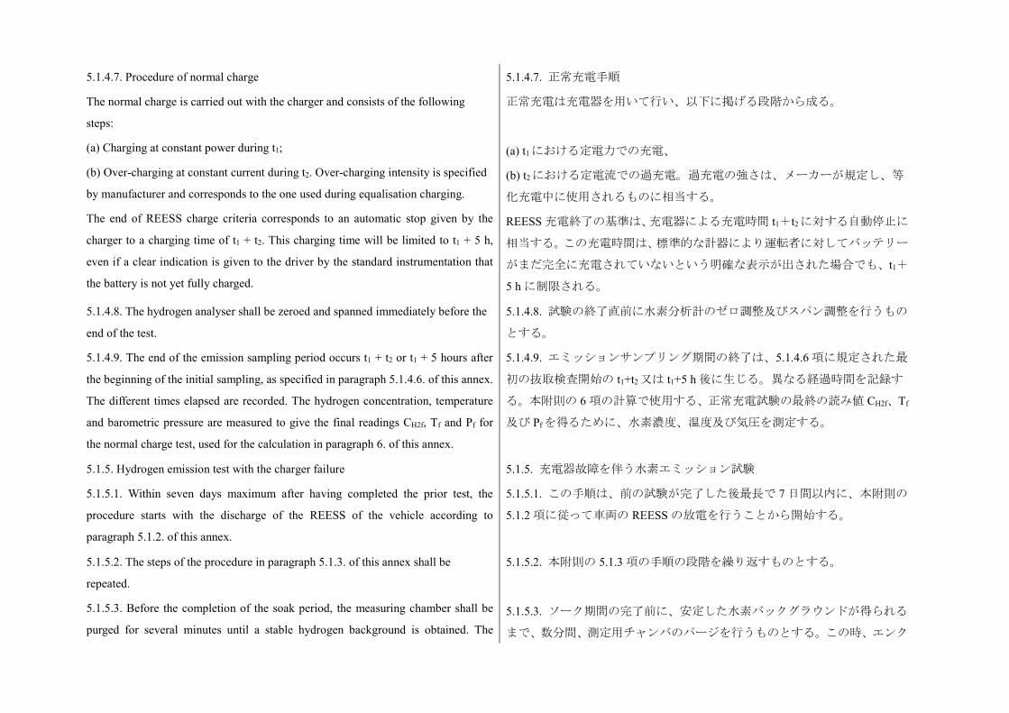
5.1.4.7. Procedure of normal charge
The normal charge is carried out with the charger and consists of the following
steps:
(a) Charging at constant power during t1;
(b) Over-charging at constant current during t2. Over-charging intensity is specified
by manufacturer and corresponds to the one used during equalisation charging.
The end of REESS charge criteria corresponds to an automatic stop given by the
charger to a charging time of t1 + t2. This charging time will be limited to t1 + 5 h,
even if a clear indication is given to the driver by the standard instrumentation that
the battery is not yet fully charged.
5.1.4.7. 正常充電手順
正常充電は充電器を用いて行い、以下に掲げる段階から成る。
(a) t1における定電力での充電、
(b) t2における定電流での過充電。過充電の強さは、メーカーが規定し、等
化充電中に使用されるものに相当する。
REESS 充電終了の基準は、充電器による充電時間 t1+t2 に対する自動停止に
相当する。この充電時間は、標準的な計器により運転者に対してバッテリー
がまだ完全に充電されていないという明確な表示が出された場合でも、t1+
5 h に制限される。
5.1.4.8. The hydrogen analyser shall be zeroed and spanned immediately before the
end of the test.
5.1.4.9. The end of the emission sampling period occurs t1 + t2 or t1 + 5 hours after
the beginning of the initial sampling, as specified in paragraph 5.1.4.6. of this annex.
The different times elapsed are recorded. The hydrogen concentration, temperature
and barometric pressure are measured to give the final readings CH2f, Tf and Pf for
the normal charge test, used for the calculation in paragraph 6. of this annex.
5.1.4.8. 試験の終了直前に水素分析計のゼロ調整及びスパン調整を行うもの
とする。
5.1.4.9. エミッションサンプリング期間の終了は、5.1.4.6 項に規定された最
初の抜取検査開始の t1+t2又は t1+5 h 後に生じる。異なる経過時間を記録す
る。本附則の 6 項の計算で使用する、正常充電試験の最終の読み値 CH2f、Tf
及び Pf を得るために、水素濃度、温度及び気圧を測定する。
5.1.5. Hydrogen emission test with the charger failure
5.1.5.1. Within seven days maximum after having completed the prior test, the
procedure starts with the discharge of the REESS of the vehicle according to
paragraph 5.1.2. of this annex.
5.1.5. 充電器故障を伴う水素エミッション試験
5.1.5.1. この手順は、前の試験が完了した後最長で 7 日間以内に、本附則の
5.1.2 項に従って車両の REESS の放電を行うことから開始する。
5.1.5.2. The steps of the procedure in paragraph 5.1.3. of this annex shall be
repeated.
5.1.5.3. Before the completion of the soak period, the measuring chamber shall be
purged for several minutes until a stable hydrogen background is obtained. The
5.1.5.2. 本附則の 5.1.3 項の手順の段階を繰り返すものとする。
5.1.5.3. ソーク期間の完了前に、安定した水素バックグラウンドが得られる
まで、数分間、測定用チャンバのパージを行うものとする。この時、エンク
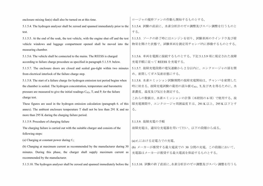
enclosure mixing fan(s) shall also be turned on at this time. ロージャの撹拌ファンの作動も開始するものとする。
5.1.5.4. The hydrogen analyser shall be zeroed and spanned immediately prior to the
test.
5.1.5.4. 試験の直前に、水素分析計のゼロ調整及びスパン調整を行うものと
する。
5.1.5.5. At the end of the soak, the test vehicle, with the engine shut off and the test
vehicle windows and luggage compartment opened shall be moved into the
measuring chamber.
5.1.5.5. ソークの終了時にはエンジンを切り、試験車両のウインドウ及び荷
物室を開けた状態で、試験車両を測定用チャンバ内に移動するものとする。
5.1.5.6. The vehicle shall be connected to the mains. The REESS is charged
according to failure charge procedure as specified in paragraph 5.1.5.9. below.
5.1.5.7. The enclosure doors are closed and sealed gas-tight within two minutes
from electrical interlock of the failure charge step.
5.1.5.6. 車両を電源に接続するものとする。下記 5.1.5.9 項に規定された故障
充電手順に従って REESS を充電する。
5.1.5.7. 故障充電段階の電気連動から 2 分以内に、エンクロージャの扉を閉
め、密閉してガス気密状態にする。
5.1.5.8. The start of a failure charge for hydrogen emission test period begins when
the chamber is sealed. The hydrogen concentration, temperature and barometric
pressure are measured to give the initial readings CH2i, Ti and Pi for the failure
charge test.
These figures are used in the hydrogen emission calculation (paragraph 6. of this
annex). The ambient enclosure temperature T shall not be less than 291 K and no
more than 295 K during the charging failure period.
5.1.5.8. 水素エミッション試験期間の故障充電開始は、チャンバを密閉した
時に始まる。故障充電試験の最初の読み値 CH2i、Ti 及び Piを得るために、水
素濃度、温度及び気圧を測定する。
これらの数値は、水素エミッションの計算(本附則の 6 項)で使用する。故
障充電期間中、エンクロージャ周囲温度 T は、291 K 以上、295 K 以下とす
る。
5.1.5.9. Procedure of charging failure
The charging failure is carried out with the suitable charger and consists of the
following steps:
(a) Charging at constant power during t'1;
(b) Charging at maximum current as recommended by the manufacturer during 30
minutes. During this phase, the charger shall supply maximum current as
recommended by the manufacturer.
5.1.5.9. 故障充電の手順
故障充電は、適切な充電器を用いて行い、以下の段階から成る。
(a) t'1 における定電力での充電、
(b) メーカーが推奨する最大電流での 30 分間の充電。この段階において、
充電器はメーカーが推奨する最大電流を供給するものとする。
5.1.5.10. The hydrogen analyser shall be zeroed and spanned immediately before the 5.1.5.10. 試験の終了直前に、水素分析計のゼロ調整及びスパン調整を行うも
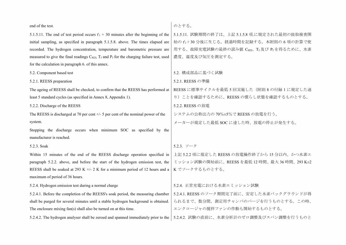
end of the test. のとする。
5.1.5.11. The end of test period occurs t'1 + 30 minutes after the beginning of the
initial sampling, as specified in paragraph 5.1.5.8. above. The times elapsed are
recorded. The hydrogen concentration, temperature and barometric pressure are
measured to give the final readings CH2f, Tf and Pf for the charging failure test, used
for the calculation in paragraph 6. of this annex.
5.1.5.11. 試験期間の終了は、上記 5.1.5.8 項.に規定された最初の抜取検査開
始の t'1+30 分後に生じる。経過時間を記録する。本附則の 6 項の計算で使
用する、故障充電試験の最終の読み値 CH2f、Tf 及び Pf を得るために、水素
濃度、温度及び気圧を測定する。
5.2. Component based test
5.2.1. REESS preparation
The ageing of REESS shall be checked, to confirm that the REESS has performed at
least 5 standard cycles (as specified in Annex 8, Appendix 1).
5.2. 構成部品に基づく試験
5.2.1. REESS の準備
REESS に標準サイクルを最低 5 回実施した(附則 8 の付録 1 に規定した通
り)ことを確認するために、REESS の慣らし状態を確認するものとする。
5.2.2. Discharge of the REESS
The REESS is discharged at 70 per cent +/- 5 per cent of the nominal power of the
system.
Stopping the discharge occurs when minimum SOC as specified by the
manufacturer is reached.
5.2.2. REESS の放電
システムの公称出力の 70%±5%で REESS の放電を行う。
メーカーが規定した最低 SOC に達した時、放電の停止が発生する。
5.2.3. Soak
Within 15 minutes of the end of the REESS discharge operation specified in
paragraph 5.2.2. above, and before the start of the hydrogen emission test, the
REESS shall be soaked at 293 K +/- 2 K for a minimum period of 12 hours and a
maximum of period of 36 hours.
5.2.3. ソーク
上記 5.2.2 項に規定した REESS の放電操作終了から 15 分以内、かつ水素エ
ミッション試験の開始前に、REESS を最低 12 時間、最大 36 時間、293 K±2
K でソークするものとする。
5.2.4. Hydrogen emission test during a normal charge
5.2.4.1. Before the completion of the REESS's soak period, the measuring chamber
shall be purged for several minutes until a stable hydrogen background is obtained.
The enclosure mixing fan(s) shall also be turned on at this time.
5.2.4. 正常充電における水素エミッション試験
5.2.4.1. REESS のソーク期間完了前に、安定した水素バックグラウンドが得
られるまで、数分間、測定用チャンバのパージを行うものとする。この時、
エンクロージャの撹拌ファンの作動も開始するものとする。
5.2.4.2. The hydrogen analyser shall be zeroed and spanned immediately prior to the 5.2.4.2. 試験の直前に、水素分析計のゼロ調整及びスパン調整を行うものと
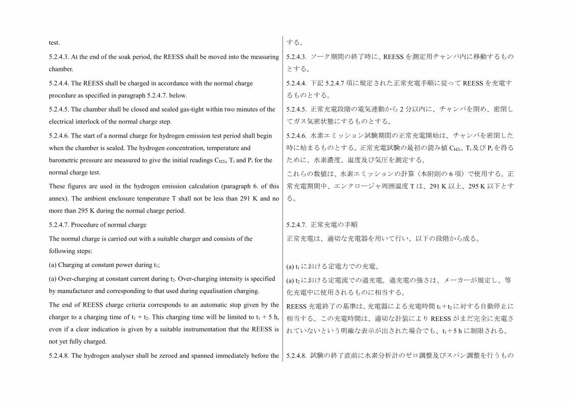
test. する。
5.2.4.3. At the end of the soak period, the REESS shall be moved into the measuring
chamber.
5.2.4.3. ソーク期間の終了時に、REESS を測定用チャンバ内に移動するもの
とする。
5.2.4.4. The REESS shall be charged in accordance with the normal charge
procedure as specified in paragraph 5.2.4.7. below.
5.2.4.5. The chamber shall be closed and sealed gas-tight within two minutes of the
electrical interlock of the normal charge step.
5.2.4.4. 下記 5.2.4.7 項に規定された正常充電手順に従って REESS を充電す
るものとする。
5.2.4.5. 正常充電段階の電気連動から 2 分以内に、チャンバを閉め、密閉し
てガス気密状態にするものとする。
5.2.4.6. The start of a normal charge for hydrogen emission test period shall begin
when the chamber is sealed. The hydrogen concentration, temperature and
barometric pressure are measured to give the initial readings CH2i, Ti and Pi for the
normal charge test.
These figures are used in the hydrogen emission calculation (paragraph 6. of this
annex). The ambient enclosure temperature T shall not be less than 291 K and no
more than 295 K during the normal charge period.
5.2.4.6. 水素エミッション試験期間の正常充電開始は、チャンバを密閉した
時に始まるものとする。正常充電試験の最初の読み値 CH2i、Ti及び Pi を得る
ために、水素濃度、温度及び気圧を測定する。
これらの数値は、水素エミッションの計算(本附則の 6 項)で使用する。正
常充電期間中、エンクロージャ周囲温度 T は、291 K 以上、295 K 以下とす
る。
5.2.4.7. Procedure of normal charge
The normal charge is carried out with a suitable charger and consists of the
following steps:
(a) Charging at constant power during t1;
(a) Over-charging at constant current during t2. Over-charging intensity is specified
by manufacturer and corresponding to that used during equalisation charging.
The end of REESS charge criteria corresponds to an automatic stop given by the
charger to a charging time of t1 + t2. This charging time will be limited to t1 + 5 h,
even if a clear indication is given by a suitable instrumentation that the REESS is
not yet fully charged.
5.2.4.7. 正常充電の手順
正常充電は、適切な充電器を用いて行い、以下の段階から成る。
(a) t1における定電力での充電、
(a) t2における定電流での過充電。過充電の強さは、メーカーが規定し、等
化充電中に使用されるものに相当する。
REESS 充電終了の基準は、充電器による充電時間 t1+t2 に対する自動停止に
相当する。この充電時間は、適切な計装により REESS がまだ完全に充電さ
れていないという明確な表示が出された場合でも、t1+5 h に制限される。
5.2.4.8. The hydrogen analyser shall be zeroed and spanned immediately before the 5.2.4.8. 試験の終了直前に水素分析計のゼロ調整及びスパン調整を行うもの
end of the test. とする。
5.2.4.9. The end of the emission sampling period occurs t1 + t2 or t1 + 5 h after the
beginning of the initial sampling, as specified in paragraph 5.2.4.6. above. The
different times elapsed are recorded. The hydrogen concentration, temperature and
barometric pressure are measured to give the final readings CH2f, Tf and Pf for the
normal charge test, used for the calculation in paragraph 6. of this annex
5.2.4.9. エミッションサンプリング期間の終了は、上記 5.2.4.6 項に規定され
た最初の抜取検査開始の t1+t2又は t1+5 h 後に生じる。異なる経過時間を記
録する。本附則の 6.項の計算で使用する、正常充電試験の最終の読み値 CH2f、
Tf 及び Pfを得るために、水素濃度、温度及び気圧を測定する。
5.2.5. Hydrogen emission test with the charger failure 5.2.5. 充電器故障を伴う水素エミッション試験
5.2.5.1. The test procedure shall start within a maximum of seven days after having
completed the test in paragraph 5.2.4. above, the procedure shall start with the
discharge of the REESS of the vehicle in accordance with paragraph 5.2.2. above.
5.2.5.2. The steps of the procedure in paragraph 5.2.3. above shall be repeated.
5.2.5.1. 上記 5.2.4 項の試験の完了後、最長で 7 日間以内に試験手順を開始す
るものとし、上記 5.2.2 項に従って車両の REESS の放電を行うことから当該
手順を開始するものとする。
5.2.5.2. 上記 5.2.3.項の手順の段階を繰り返すものとする。
5.2.5.3. Before the completion of the soak period, the measuring chamber shall be
purged for several minutes until a stable hydrogen background is obtained. The
enclosure mixing fan(s) shall also be turned on at this time.
5.2.5.3. ソーク期間の完了前に、安定した水素バックグラウンドが得られる
まで、数分間、測定用チャンバのパージを行うものとする。この時、エンク
ロージャの撹拌ファンの作動も開始するものとする。
5.2.5.4. The hydrogen analyser shall be zeroed and spanned immediately prior to the
test.
5.2.5.4. 試験の直前に、水素分析計のゼロ調整及びスパン調整を行うものと
する。
5.2.5.5. At the end of the soak the REESS shall be moved into the measuring
chamber.
5.2.5.5. ソークの終了時には、REESS を測定用チャンバ内に移動するものと
する。
5.2.5.6. The REESS shall be charged according to the failure charge procedure as
specified in paragraph 5.2.5.9. below.
5.2.5.7. The chamber shall be closed and sealed gas-tight within two minutes from
electrical interlock of the failure charge step.
5.2.5.6. 下記 5.2.5.9 項に規定された故障充電手順に従って REESS を充電す
るものとする。
5.2.5.7. 故障充電段階の電気連動から 2 分以内に、チャンバを閉め、密閉し
てガス気密状態にするものとする。
5.2.5.8. The start of a failure charge for hydrogen emission test period begins when
the chamber is sealed. The hydrogen concentration, temperature and barometric
pressure are measured to give the initial readings CH2i, Ti and Pi for the failure
5.2.5.8. 水素エミッション試験期間の故障充電の開始は、チャンバを密閉し
た時に始まるものとする。故障充電試験の最初の CH2i、Ti及び Pi を得るため
に、水素濃度、温度及び気圧を測定する。
charge test.
These figures are used in the hydrogen emission calculation (paragraph 6. of this
annex). The ambient enclosure temperature T shall not be less than 291 K and no
more than 295 K during the charging failure period.
これらの数値は、水素エミッションの計算(本附則の 6 項)で使用する。故
障充電期間中、エンクロージャ周囲温度 T は、291 K 以上、295 K 以下とす
る。
5.2.5.9. Procedure of charging failure
The charging failure is carried out with a suitable charger and consists of the
following steps:
(a) Charging at constant power during t'1,
(b) Charging at maximum current as recommended by the manufacturer during 30
minutes. During this phase, the charger shall supply maximum current as
recommended by the manufacturer.
5.2.5.9. 故障充電の手順
故障充電は、適切な充電器を用いて行い、以下の段階から成る。
(a) t'1 における定電力での充電、
(b) メーカーが推奨する最大電流での 30 分間の充電。この段階において、
充電器はメーカーが推奨する最大電流を供給するものとする。
5.2.5.10. The hydrogen analyser shall be zeroed and spanned immediately before the
end of the test.
5.2.5.10. 試験の終了直前に、水素分析計のゼロ調整及びスパン調整を行うも
のとする。
5.2.5.11. The end of test period occurs t'1 + 30 minutes after the beginning of the
initial sampling, as specified in paragraph 5.2.5.8. above. The times elapsed are
recorded. The hydrogen concentration, temperature and barometric pressure are
measured to give the final readings CH2f, Tf and Pf for the charging failure test, used
for the calculation in paragraph 6. below.
5.2.5.11. 試験期間の終了は、上記 5.2.5.8 項に規定された最初の抜取検査開
始の t'1+30 分後に生じる。経過時間を記録する。下記 6 項の計算で使用す
る、故障充電試験の最終の読み値 CH2f、Tf及び Pf を得るために、水素濃度、
温度及び気圧を測定する。
6. Calculation
The hydrogen emission tests described in paragraph 5. above allow the calculation
of the hydrogen emissions from the normal charge and charging failure phases.
Hydrogen emissions from each of these phases are calculated using the initial and
final hydrogen concentrations, temperatures and pressures in the enclosure, together
with the net enclosure volume.
6. 計算
上記 5 項に規定された水素エミッション試験により、正常充電及び故障充電
段階からの水素エミッションの計算が可能となる。最初及び最終のエンクロ
ージャ内の水素濃度、温度及び圧力並びにエンクロージャ純容積を用いて、
これらの各段階からの水素エミッションを計算する。
下記の式を使用する。
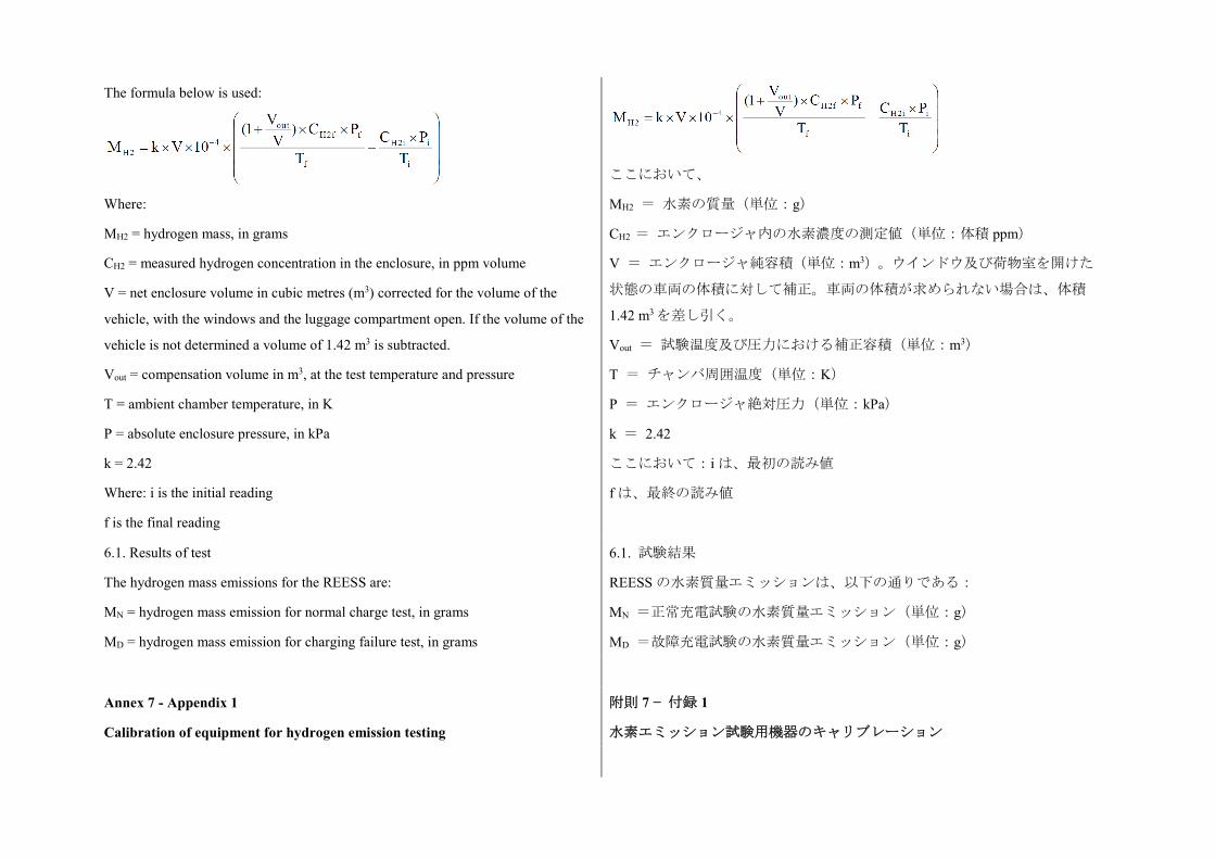
The formula below is used:
Where:
MH2 = hydrogen mass, in grams
CH2 = measured hydrogen concentration in the enclosure, in ppm volume
V = net enclosure volume in cubic metres (m3) corrected for the volume of the
vehicle, with the windows and the luggage compartment open. If the volume of the
vehicle is not determined a volume of 1.42 m3 is subtracted.
Vout = compensation volume in m3, at the test temperature and pressure
T = ambient chamber temperature, in K
P = absolute enclosure pressure, in kPa
k = 2.42
Where: i is the initial reading
f is the final reading
ここにおいて、
MH2 = 水素の質量(単位:g)
CH2 = エンクロージャ内の水素濃度の測定値(単位:体積 ppm)
V = エンクロージャ純容積(単位:m3)。ウインドウ及び荷物室を開けた
状態の車両の体積に対して補正。車両の体積が求められない場合は、体積
1.42 m3 を差し引く。
Vout = 試験温度及び圧力における補正容積(単位:m3)
T = チャンバ周囲温度(単位:K)
P = エンクロージャ絶対圧力(単位:kPa)
k = 2.42
ここにおいて:i は、最初の読み値
f は、最終の読み値
6.1. Results of test
The hydrogen mass emissions for the REESS are:
MN = hydrogen mass emission for normal charge test, in grams
MD = hydrogen mass emission for charging failure test, in grams
6.1. 試験結果
REESS の水素質量エミッションは、以下の通りである:
MN =正常充電試験の水素質量エミッション(単位:g)
MD =故障充電試験の水素質量エミッション(単位:g)
Annex 7 - Appendix 1
Calibration of equipment for hydrogen emission testing
附則 7 − 付録 1
水素エミッション試験用機器のキャリブレーション
1. Calibration frequency and methods
All equipment shall be calibrated before its initial use and then calibrated as often as
necessary and in any case in the month before type approval testing. The calibration
methods to be used are described in this appendix.
1. キャリブレーション頻度及び方法
すべての機器には初めて使用する前にキャリブレーションを施し、その後は
必要に応じた頻度で、また、いかなる場合も型式認可試験の前の月には、キ
ャリブレーションを施すものとする。使用するキャリブレーション方法は、
本付録に規定する。
2. Calibration of the enclosure
2.1. Initial determination of enclosure internal volume
2. エンクロージャのキャリブレーション
2.1. エンクロージャ内部容積の初期決定
2.1.1. Before its initial use, the internal volume of the chamber shall be determined
as follows. The internal dimensions of the chamber are carefully measured, taking
into account any irregularities such as bracing struts. The internal volume of the
chamber is determined from these measurements.
The enclosure shall be latched to a fixed volume when the enclosure is held at an
ambient temperature of 293 K. This nominal volume shall be repeatable within
+/-0.5 per cent of the reported value.
2.1.1. 初めて使用する前に、以下の通りチャンバの内部容積を求めるものと
する。支柱などの不規則な部分を考慮に入れ、チャンバの内部寸法を注意深
く測定する。チャンバの内部容積は、これらの測定値から求める。
エンクロージャには、エンクロージャが周囲温度 293 K に保たれている時に
固定容積になるようラッチを掛けるものとする。この公称容積は、報告値の
±0.5%以内で再現可能であるものとする。
2.1.2. The net internal volume is determined by subtracting 1.42 m3 from the
internal volume of the chamber. Alternatively the volume of the test vehicle with the
luggage compartment and windows open or REESS may be used instead of the 1.42
m3.
2.1.3. The chamber shall be checked as in paragraph 2.3. of this annex. If the
hydrogen mass does not agree with the injected mass to within +/-2 per cent then
corrective action is required.
2.1.2. チャンバの内部容積から 1.42 m3 を差し引くことにより、純内部容積
を求める。代替として、1.42 m3 の代わりに、荷物室及びウインドウを開け
た状態の試験車両又は REESS の体積を用いてもよい。
2.1.3. 本附則の 2.3 項の通りにチャンバのチェックをするものとする。水素
の質量が投入した質量と±2%以内の精度で一致しない場合には、是正措置
が要求される。
2.2. Determination of chamber background emissions
This operation determines that the chamber does not contain any materials that emit
significant amounts of hydrogen. The check shall be carried out at the enclosure's
2.2. チャンバのバックグラウンドエミッションの測定
この作業は、チャンバが相当な量の水素を発する材料を含有していないこと
を決定するものである。エンクロージャを初めて使用する時やバックグラウ
introduction to service, after any operations in the enclosure which may affect
background emissions and at a frequency of at least once per year.
ンドエミッションに影響を及ぼすエンクロージャ内での作業の後、また少な
くとも年に 1 回の頻度で、チェックを実施するものとする。
2.2.1. Variable-volume enclosure may be operated in either latched or unlatched
volume configuration, as described in paragraph 2.1.1. above. Ambient temperature
shall be maintained at 293 K +/- 2 K, throughout the four-hour period mentioned
below.
2.2.1. 可変容積エンクロージャは、上記 2.1.1 項に規定される通り、容積構
成のラッチが掛かった状態又は解除された状態のいずれかで操作してよい。
周囲温度は、下記に言及する 4 時間の期間にわたり、293 K±2 K に保つもの
とする。
2.2.2.
The enclosure may be sealed and the mixing fan operated for a period of up to 12
hours before the four-hour background-sampling period begins.
2.2.2.
4 時間のバックグラウンドサンプリング期間が始まる前に、最長で 12 時間
の期間にわたってエンクロージャを密閉し、撹拌ファンを作動させてよい。
2.2.3. The analyser (if required) shall be calibrated, then zeroed and spanned. 2.2.3. 分析計(必要な場合)のキャリブレーション、次いでゼロ調整及びス
パン調整を行うものとする。
2.2.4. The enclosure shall be purged until a stable hydrogen reading is obtained, and
the mixing fan turned on if not already on.
2.2.5. The chamber is then sealed and the background hydrogen concentration,
temperature and barometric pressure are measured. These are the initial readings
CH2i, Ti and Pi used in the enclosure background calculation.
2.2.6. The enclosure is allowed to stand undisturbed with the mixing fan on for a
period of four hours.
2.2.4. 安定した水素の読み値が得られるまでエンクロージャのパージを行
うものとし、撹拌ファンの作動を開始する(既に作動していない場合)。
2.2.5. 次いで、チャンバを密閉し、バックグラウンド水素濃度、温度及び気
圧を測定する。これらがエンクロージャバックグラウンドの計算で使用する
最初の読み値 CH2i、Ti及び Piである。
2.2.6. 撹拌ファンを作動させたまま、4 時間、エンクロージャを放置する。
2.2.7. At the end of this time the same analyser is used to measure the hydrogen
concentration in the chamber. The temperature and the barometric pressure are also
measured. These are the final readings CH2f, Tf and Pf.
2.2.8. The change in mass of hydrogen in the enclosure shall be calculated over the
time of the test in accordance with paragraph 2.4. of this annex and shall not exceed
0.5 g.
2.2.7. この時間の終了時に、同じ分析計を用いて、チャンバ内の水素濃度を
測定する。温度及び気圧も測定する。これらが最終の読み値 CH2f、Tf及び
Pfである。
2.2.8. 本附則の 2.4 項に従った試験の時間にわたり、エンクロージャ内の水
素の質量変化を計算するものとするが、0.5 g を超えないものとする。
2.3. Calibration and hydrogen retention test of the chamber 2.3. チャンバのキャリブレーション及び水素滞留試験
The calibration and hydrogen retention test in the chamber provides a check on the
calculated volume (paragraph 2.1. above) and also measures any leak rate. The
enclosure leak rate shall be determined at the enclosure's introduction to service,
after any operations in the enclosure which may affect the integrity of the enclosure,
and at least monthly thereafter. If six consecutive monthly retention checks are
successfully completed without corrective action, the enclosure leak rate may be
determined quarterly thereafter as long as no corrective action is required.
チャンバ内のキャリブレーション及び水素滞留試験により、容積の計算値
(上記 2.1 項)のチェックができ、漏れ率の測定もできる。エンクロージャ
の漏れ率は、エンクロージャを初めて使用する時やエンクロージャの完全性
に影響を及ぼす可能性のあるエンクロージャ内での作業の後、また、その後
は少なくとも月に 1 回の頻度で、求めるものとする。月に 1 回の滞留チェッ
クが 6 回連続で是正措置なしに無事完了した場合は、その後の是正措置を要
求されない限り、エンクロージャの漏れ率を求めるのは、年に 4 回としても
よい。
2.3.1. The enclosure shall be purged until a stable hydrogen concentration is
reached. The mixing fan is turned on, if not already switched on. The hydrogen
analyser is zeroed, calibrated if required, and spanned.
2.3.1. 安定した水素濃度が達成されるまで、エンクロージャのパージを行う
ものとする。撹拌ファンの作動を開始する(既に作動していない場合)。水
素分析計のゼロ調整、キャリブレーション(必要な場合)及びスパン調整を
行う。
2.3.2. The enclosure shall be latched to the nominal volume position. 2.3.2. エンクロージャは、公称容積位置になるようにラッチを掛けるものと
する。
2.3.3. The ambient temperature control system is then turned on (if not already on)
and adjusted for an initial temperature of 293 K.
2.3.4. When the enclosure temperature stabilizes at 293 K +/- 2 K, the enclosure is
sealed and the background concentration, temperature and barometric pressure
measured. These are the initial readings CH2i, Ti and Pi used in the enclosure
calibration.
2.3.3. 次いで、周囲温度コントロールシステムの作動を開始し(既に作動し
ていない場合)、初期温度 293 K に調節する。
2.3.4. エンクロージャ温度が 293 K±2 K で安定した時、エンクロージャを密
閉し、バックグラウンド濃度、温度及び気圧を測定する。これらがエンクロ
ージャのキャリブレーションで使用する最初の読み値 CH2i、Ti及び Piであ
る。
2.3.5. The enclosure shall be unlatched from the nominal volume.
2.3.6. A quantity of approximately 100 g of hydrogen is injected into the enclosure.
This mass of hydrogen shall be measured to an accuracy of +/-2 per cent of the
measured value.
2.3.5. エンクロージャの公称容積のラッチを解除するものとする。
2.3.6. 約 100 g の量の水素をエンクロージャ内に投入する。この水素の質量
を測定値±2%の精度まで測定するものとする。
2.3.7. The contents of the chamber shall be allowed to mix for five minutes and then 2.3.7. チャンバの含有成分を 5 分間撹拌するものとし、次いで水素濃度、温
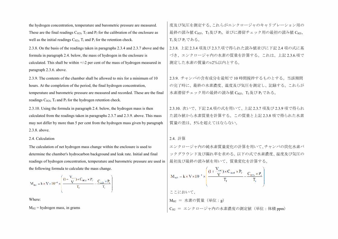
the hydrogen concentration, temperature and barometric pressure are measured.
These are the final readings CH2f, Tf and Pf for the calibration of the enclosure as
well as the initial readings CH2i, Ti and Pi for the retention check.
度及び気圧を測定する。これらがエンクロージャのキャリブレーション用の
最終の読み値 CH2f、Tf及び Pf、並びに滞留チェック用の最初の読み値 CH2i、
Ti及び Piである。
2.3.8. On the basis of the readings taken in paragraphs 2.3.4 and 2.3.7 above and the
formula in paragraph 2.4. below, the mass of hydrogen in the enclosure is
calculated. This shall be within +/-2 per cent of the mass of hydrogen measured in
paragraph 2.3.6. above.
2.3.8. 上記 2.3.4 項及び 2.3.7.項で得られた読み値並びに下記 2.4 項の式に基
づき、エンクロージャ内の水素の質量を計算する。これは、上記 2.3.6.項で
測定した水素の質量の±2%以内とする。
2.3.9. The contents of the chamber shall be allowed to mix for a minimum of 10
hours. At the completion of the period, the final hydrogen concentration,
temperature and barometric pressure are measured and recorded. These are the final
readings CH2f, Tf and Pf for the hydrogen retention check.
2.3.9. チャンバの含有成分を最短で 10 時間撹拌するものとする。当該期間
の完了時に、最終の水素濃度、温度及び気圧を測定し、記録する。これらが
水素滞留チェック用の最終の読み値 CH2f、Tf及び Pf である。
2.3.10. Using the formula in paragraph 2.4. below, the hydrogen mass is then
calculated from the readings taken in paragraphs 2.3.7 and 2.3.9. above. This mass
may not differ by more than 5 per cent from the hydrogen mass given by paragraph
2.3.8. above.
2.3.10. 次いで、下記 2.4.項の式を用いて、上記 2.3.7 項及び 2.3.9 項で得られ
た読み値から水素質量を計算する。この質量と上記 2.3.8 項で得られた水素
質量の差は、5%を超えてはならない。
2.4. Calculation
The calculation of net hydrogen mass change within the enclosure is used to
determine the chamber's hydrocarbon background and leak rate. Initial and final
readings of hydrogen concentration, temperature and barometric pressure are used in
the following formula to calculate the mass change.
Where:
MH2 = hydrogen mass, in grams
2.4. 計算
エンクロージャ内の純水素質量変化の計算を用いて、チャンバの炭化水素バ
ックグラウンド及び漏れ率を求める。以下の式で水素濃度、温度及び気圧の
最初及び最終の読み値を用いて、質量変化を計算する。
ここにおいて、
MH2 = 水素の質量(単位:g)
CH2 = エンクロージャ内の水素濃度の測定値(単位:体積 ppm)
CH2 = measured hydrogen concentration into the enclosure, in ppm volume
V = enclosure volume in cubic metres (m3) as measured in paragraph 2.1.1. above.
Vout = compensation volume in m3, at the test temperature and pressure
T = ambient chamber temperature, in K
P = absolute enclosure pressure, in kPa
k = 2.42
Where: i is the initial reading
f is the final reading
V = 上記 2.1.1 項で測定したエンクロージャ容積(単位:m3)
Vout = 試験温度及び圧力における補正容積(単位:m3)
T = チャンバ周囲温度(単位:K)
P = エンクロージャ絶対圧力(単位:kPa)
k = 2.42
ここにおいて:i は、最初の読み値
f は、最終の読み値
3. Calibration of the hydrogen analyser
The analyser should be calibrated using hydrogen in air and purified synthetic air.
See paragraph 4.8.2. of Annex 7.
Each of the normally used operating ranges are calibrated by the following
procedure:
3. 水素分析計のキャリブレーション
分析計のキャリブレーションは、空気中及び精製合成空気中の水素を用いて
行うべきものとする。附則 7 の 4.8.2 項を参照。
通常使用する各作動範囲に、以下の手順によりキャリブレーションを施す。
3.1. Establish the calibration curve by at least five calibration points spaced as
evenly as possible over the operating range. The nominal concentration of the
calibration gas with the highest concentrations to be at least 80 per cent of the full
scale.
3.1. 作動範囲にわたり可能な限り等間隔に配置した少なくとも 5 つのキャ
リブレーションを施す点からキャリブレーション曲線を定める。最も濃度が
高いキャリブレーションガスの公称濃度は、少なくともフルスケールの
80%。
3.2. Calculate the calibration curve by the method of least squares. If the resulting
polynomial degree is greater than three, then the number of calibration points shall
be at least the number of the polynomial degree plus two.
3.2. 最小二乗法によりキャリブレーション曲線を計算する。得られた多項式
次数が 3 を超える場合には、キャリブレーションを施す点の数は、少なくと
も多項式次数の数+2 とする。
3.3. The calibration curve shall not differ by more than two per cent from the
nominal value of each calibration gas.
3.3. キャリブレーション曲線と各キャリブレーションガスの公称値の差は、
2%を超えないものとする。
3.4. Using the coefficients of the polynomial derived from paragraph 3.2. above, a 3.4. 上記 3.2 項から得られた多項式の係数を用いて、真の濃度に対する分析
table of analyser readings against true concentrations shall be drawn by steps no
greater than 1 per cent of full scale. This is to be carried out for each analyser range
calibrated.
This table shall also contain other relevant data such as:
(a) Date of calibration;
(b) Span and zero potentiometer readings (where applicable);
(c) Nominal scale;
(d) Reference data of each calibration gas used;
(e) Real and indicated value of each calibration gas used together with the
percentage differences;
(f) Calibration pressure of analyser.
計の読み値の表を、フルスケールの 1%以下の段階を用いて作成するものと
する。これは、キャリブレーションを施した各分析計範囲に対して実施する。
この表には、下記などのその他の関連データも含むものとする。
(a) キャリブレーション実施日、
(b) ゼロ及びスパンの電位差計の読み値(該当する場合)、
(c) 公称スケール、
(d) 使用した各キャリブレーションガスの参考データ、
(e) 使用した各キャリブレーションガスの実際の値及び表示値並びにパー
センテージの差、
(f) 分析計に施すキャリブレーションの圧力。
3.5. Alternative methods (e.g. computer, electronically controlled range switch) can
be used if it is proven to the technical service that these methods give equivalent
accuracy.
3.5. 代替方法(例:コンピュータ、電子的に制御された範囲スイッチ)は、
これらの方法により同等の精度が達成されることを技術機関に証明した場
合には、使用することができる。
Annex 7 - Appendix 2
Essential characteristics of the vehicle family
附則 7 − 付録 2
車両ファミリーの基本特性
1. Parameters defining the family relative to hydrogen emissions
The family may be defined by basic design parameters which shall be common to
vehicles within the family. In some cases there may be interaction of parameters.
These effects shall also be taken into consideration to ensure that only vehicles with
similar hydrogen emission characteristics are included within the family.
1. 水素エミッションに関するファミリーを定義するパラメーター
ファミリーは、ファミリー内の車両に共通するものとする基本設計パラメー
ターにより定義することができる。パラメーターの相互作用がある場合もあ
る。類似する水素エミッション特性を有する車両のみがファミリー内に含ま
れることを確保するために、これらの作用も考慮に入れるものとする。
2. To this end, those vehicle types whose parameters described below are identical
are considered to belong to the same hydrogen emissions.
2. この目的のために、下記に記載するパラメーターが同じである車両型式
は、同じ水素エミッションに属しているとみなす。
REESS:
(a) Trade name or mark of theREESS;
(b) Indication of all types of electrochemical couples used;
(c) Number of REESS cells;
(d) Number of REESS subsystems;
(e) Nominal voltage of the REESS (V);
(f) REESS energy (kWh);
(g) Gas combination rate (in per cent);
(h) Type(s) of ventilation for REESS subsystem(s);
(i) Type of cooling system (if any).
On-board charger:
(a) Make and type of different charger parts;
(b) Output nominal power (kW);
(c) Maximum voltage of charge (V);
(d) Maximum intensity of charge (A);
(e) Make and type of control unit (if any);
(f) Diagram of operating, controls and safety;
(g) Characteristics of charge periods.
REESS:
(a) REESS の商品名又は商標、
(b) 使用する電気化学対の全型式の表示、
(c) REESS 電池の数、
(d) REESS サブシステムの数、
(e) REESS の公称電圧(V)、
(f) REESS エネルギー(kWh)、
(g) ガス結合率(%)、
(h) REESS サブシステムの換気装置の型式、
(i) 冷却システムの型式(ある場合)。
車載充電器:
(a) 各充電器部品の機種及び型式、
(b) 公称出力(kW)、
(c) 最大充電電圧(V)、
(d) 最大充電電流(A)、
(e) コントロールユニットの機種及び型式(ある場合)、
(f) 作動、コントロール装置及び安全の略図、
(g) 充電期間の特性。
Annex 8
REESS test procedures
附則 8
REESS 試験手順
Annex 8 - Appendix 1 附則 8 − 付録 1
Procedure for conducting a standard cycle
A standard cycle will start with a standard discharge followed by a standard charge.
Standard discharge:
Discharge rate: The discharge procedure including termination criteria shall be
defined by the manufacturer. If not specified, then it shall be a discharge with 1C
current.
Discharge limit (end voltage): Specified by the manufacturer
Rest period after discharge: Minimum 30 min
Standard charge: The charge procedure including termination criteria shall be
defined by the manufacturer. If not specified, then it shall be a charge with C/3
current.
標準サイクルを実施する手順
標準サイクルは標準放電から開始し、続いて標準充電を実施する。
標準放電:
放電率:停止基準を含む放電手順は、メーカーが定めるものとする。規定さ
れていない場合は、1C 電流での放電とする。
放電限界(終了電圧):メーカーが規定する
放電後の休止期間:最低 30 分間
標準充電:停止基準を含む充電手順は、メーカーが定めるものとする。規定
されていない場合は、C/3 電流での充電とする。
Annex 8A
Vibration test
附則 8A
振動試験
1. Purpose
The purpose of this test is to verify the safety performance of the REESS under a
vibration environment which the REESS will likely experience during the normal
operation of the vehicle.
1. 目的
本試験の目的は、車両の通常走行中に REESS が受ける可能性のある振動環
境下における REESS の安全性能を検証することである。
2. Installations
2.1. This test shall be conducted either with the complete REESS or with a related
REESS subsystem(s) including the cells and their electrical connections. If the
manufacturer chooses to test with related subsystem(s), the manufacturer shall
2. 設備
2.1. 本試験は、完全 REESS 又は電池及び電気結線を含む関連の REESS サブ
システムのいずれかを用いて実施するものとする。メーカーが関連のサブシ
ステムを用いて試験することを選択する場合は、当該のメーカーは、試験結
demonstrate that the test result can reasonably represent the performance of the
complete REESS with respect to its safety performance under the same conditions.
If the electronic management unit for the REESS is not integrated in the casing
enclosing the cells, then the electronic management unit may be omitted from
installation on the tested-device if so requested by the manufacturer.
2.2. The tested-device shall be firmly secured to the platform of the vibration
machine in such a manner as to ensure that the vibrations are directly transmitted to
the tested-device.
果が、同一条件下の安全性能に関して、完全 REESS の性能を合理的に代表
することができることを証明するものとする。REESS の電子管理ユニット
が電池の入っているケーシングと一体化していない場合は、メーカーからの
要請があれば、当該電子管理ユニットを試験対象装置の設備から省くことが
できる。
2.2. 試験対象装置を、振動が確実に直接試験対象装置に伝わるように、振動
発生機のプラットフォームにしっかりと固定するものとする。
3. Procedures
3.1. General test conditions
The following conditions shall apply to the tested-device:
(a) The test shall be conducted at an ambient temperature of 20 +/- 10 deg. C;
(b) At the beginning of the test, the SOC shall be adjusted to a value in the upper 50
per cent of the normal operating SOC range of the tested-device;
(c) At the beginning of the test, all protection devices which affect the function(s) of
the tested-device that are relevant to the outcome of the test shall be operational.
3. 手順
3.1. 一般試験条件
以下の条件を試験対象装置に適用するものとする。
(a) 試験は周囲温度 20±10℃で実施されるものとする、
(b) 試験開始時に、SOC を試験対象装置の通常作動 SOC 範囲の上位 50%内
の任意の値に調整するものとする、
(c) 試験開始時に、試験対象装置の機能に影響を与え、かつ試験結果に関連
するすべての保護装置は作動可能な状態とする。
3.2. Test procedures
The tested-devices shall be subjected to a vibration having a sinusoidal waveform
with a logarithmic sweep between 7 Hz and 50 Hz and back to 7 Hz traversed in 15
minutes. This cycle shall be repeated 12 times for a total of 3 hours in the vertical
direction of the mounting orientation of the REESS as specified by the
manufacturer.
The correlation between frequency and acceleration shall be as shown in Table 1:
3.2. 試験手順
試験対象装置に、7 Hz から 50 Hz の対数掃引で 7 Hz に戻る正弦波形を有す
る振動を 15 分間与えるものとする。メーカーが規定した REESS の取り付け
方向の垂直方向に、このサイクルを合計 3 時間で 12 回繰り返すものとする。
周波数と加速度との相関関係を表 1 に示すものとする。
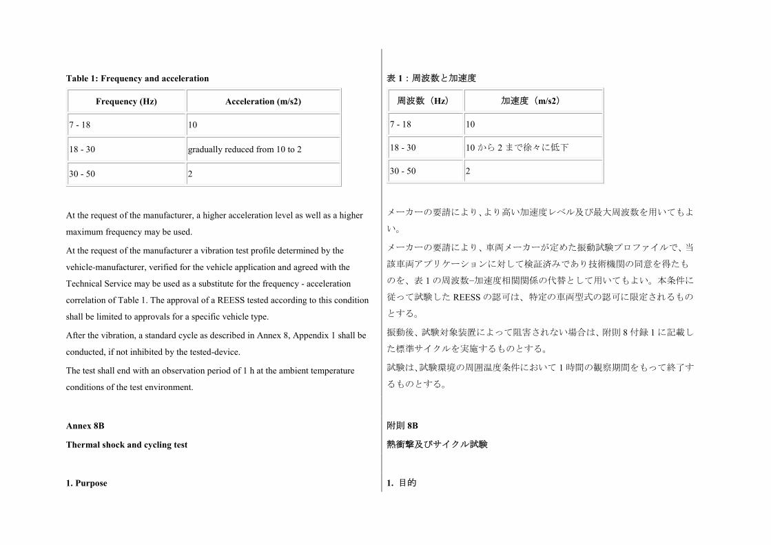
Table 1: Frequency and acceleration
Frequency (Hz) Acceleration (m/s2)
7 - 18 10
18 - 30 gradually reduced from 10 to 2
30 - 50 2
At the request of the manufacturer, a higher acceleration level as well as a higher
maximum frequency may be used.
At the request of the manufacturer a vibration test profile determined by the
vehicle-manufacturer, verified for the vehicle application and agreed with the
Technical Service may be used as a substitute for the frequency - acceleration
correlation of Table 1. The approval of a REESS tested according to this condition
shall be limited to approvals for a specific vehicle type.
After the vibration, a standard cycle as described in Annex 8, Appendix 1 shall be
conducted, if not inhibited by the tested-device.
The test shall end with an observation period of 1 h at the ambient temperature
conditions of the test environment.
表 1:周波数と加速度
周波数(Hz) 加速度(m/s2)
7 - 18 10
18 - 30 10 から 2 まで徐々に低下
30 - 50 2
メーカーの要請により、より高い加速度レベル及び最大周波数を用いてもよ
い。
メーカーの要請により、車両メーカーが定めた振動試験プロファイルで、当
該車両アプリケーションに対して検証済みであり技術機関の同意を得たも
のを、表 1 の周波数−加速度相関関係の代替として用いてもよい。本条件に
従って試験した REESS の認可は、特定の車両型式の認可に限定されるもの
とする。
振動後、試験対象装置によって阻害されない場合は、附則 8 付録 1 に記載し
た標準サイクルを実施するものとする。
試験は、試験環境の周囲温度条件において 1 時間の観察期間をもって終了す
るものとする。
Annex 8B
Thermal shock and cycling test
附則 8B
熱衝撃及びサイクル試験
1. Purpose 1. 目的
The purpose of this test is to verify the resistance of the REESS to sudden changes
in temperature. The REESS shall undergo a specified number of temperature cycles,
which start at ambient temperature followed by high and low temperature cycling. It
simulates a rapid environmental temperature change which a REESS would likely
experience during its life.
本試験の目的は、急な温度変化に対する REESS の耐性を検証することであ
る。REESS に対して、周囲温度、続いて高温、低温のサイクルで所定の数
の温度サイクルを実施するものとする。これは、REESS がその耐用期間中
に受ける可能性のある急激な環境温度変化を再現したものである。
2. Installations
This test shall be conducted either with the complete REESS or with related REESS
subsystem(s) of the REESS including the cells and their electrical connections. If
the manufacturer chooses to test with related subsystem(s), the manufacturer shall
demonstrate that the test result can reasonably represent the performance of the
complete REESS with respect to its safety performance under the same conditions.
If the electronic management unit for the REESS is not integrated in the casing
enclosing the cells, then the electronic management unit may be omitted from
installation on the tested-device if so requested by the manufacturer.
2. 設備
本試験は、完全 REESS 又は電池及び電気結線を含む関連の REESS サブシス
テムのいずれかを用いて実施するものとする。メーカーが関連のサブシステ
ムを用いて試験することを選択する場合は、当該のメーカーは、試験結果が、
同一条件下の安全性能に関して、完全 REESS の性能を合理的に代表するこ
とができることを証明するものとする。REESS の電子管理ユニットが、電
池の入っているケーシングと一体化していない場合は、メーカーからの要請
があれば、当該電子管理ユニットを試験対象装置の設備から省くことができ
る。
3. Procedures
3.1. General test conditions
The following conditions shall apply to the tested-device at the start of the test:
(a) The SOC shall be adjusted to a value in the upper 50 per cent of the normal
operating SOC range;
(b) All protection devices, which would affect the function of the tested-device and
which are relevant to the outcome of the test shall be operational.
3. 手順
3.1. 一般試験条件
以下の条件を試験開始時に試験対象装置に適用するものとする。
(a) SOC を通常作動 SOC 範囲の上位 50%内の任意の値に調整するものとす
る、
(b) 試験対象装置の機能に影響を与え、かつ試験結果に関連するすべての保
護装置は作動可能な状態とする。
3.2. Test procedure
The tested-device shall be stored for at least six hours at a test temperature equal to
3.2. 試験手順
試験対象装置を 60±2℃、又はメーカーの要請がある場合はそれより高い試
60 +/- 2 deg. C or higher if requested by the manufacturer, followed by storage for
at least six hours at a test temperature equal to -40 +/- 2 deg. C or lower if requested
by the manufacturer. The maximum time interval between test temperature extremes
shall be 30 minutes. This procedure shall be repeated until a minimum of 5 total
cycles are completed, after which the tested-device shall be stored for 24 hours at an
ambient temperature of 20 +/- 10 deg. C.
After the storage for 24 hours, a standard cycle as described in Annex 8, Appendix 1
shall be conducted, if not inhibited by the tested-device.
The test shall end with an observation period of 1 h at the ambient temperature
conditions of the test environment.
験温度で少なくとも 6 時間、続いて-40±2℃又はメーカーの要請がある場合
はそれより低い試験温度で少なくとも 6 時間置くものとする。試験の極限温
度間の最大時間間隔は 30 分とする。この試験手順を、最低でも合計 5 回の
サイクルが完了するまで繰り返すものとし、その後、試験対象装置を
20±10℃の周囲温度に 24 時間置くものとする。
24 時間置いた後、試験対象装置によって阻害されない場合は、附則 8 付録 1
に記載した標準サイクルを実施するものとする。
試験は、試験環境の周囲温度条件において 1 時間の観察期間をもって終了す
るものとする。
Annex 8C
Mechanical shock
附則 8C
メカニカルショック
1. Purpose
The purpose of this test is to verify the safety performance of the REESS under
inertial loads which may occur during a vehicle crash.
1. 目的
本試験の目的は、車両衝突時に生じる可能性のある慣性荷重下における
REESS の安全性能を検証することである。
2. Installation
2.1. This test shall be conducted either with the complete REESS or with related
REESS subsystem(s) including the cells and their electrical connections. If the
manufacturer chooses to test with related subsystem(s), the manufacturer shall
demonstrate that the test result can reasonably represent the performance of the
complete REESS with respect to its safety performance under the same conditions.
If the electronic management unit for the REESS is not integrated in the casing
2. 設備
2.1. 本試験は、完全 REESS 又は電池及び電気結線を含む関連の REESS サブ
システムのいずれかを用いて実施するものとする。メーカーが関連のサブシ
ステムを用いて試験することを選択する場合は、当該のメーカーは、試験結
果が、同一条件下の安全性能に関して、完全 REESS の性能を合理的に代表
することができることを証明するものとする。REESS の電子管理ユニット
が、電池の入っているケーシングと一体化していない場合は、メーカーから
enclosing the cells, then the electronic management unit may be omitted from
installation on the tested-device if so requested by the manufacturer.
2.2. The tested-device shall be connected to the test fixture only by the intended
mountings provided for the purpose of attaching the REESS or REESS subsystem to
the vehicle.
の要請があれば、当該電子管理ユニットを試験対象装置の設備から省くこと
ができる。
2.2. REESS 又は REESS サブシステムを車両に取り付けるために装備された
取り付け台によってのみ、試験対象装置を試験装置に接続するものとする。
3. Procedures
3.1. General test conditions and requirements
The following condition shall apply to the test:
(a) The test shall be conducted at an ambient temperature of 20 +/- 10 deg. C,
(b) At the beginning of the test, the SOC shall be adjusted to a value in the upper 50
per cent of the normal operating SOC range;
(c) At the beginning of the test, all protection devices which effect the function of
the tested-device and which are relevant to the outcome of the test, shall be
operational.
3. 手順
3.1. 一般試験条件及び要件
以下の条件を試験に適用するものとする。
(a) 試験は周囲温度 20±10℃で実施されるものとする、
(b) 試験開始時に、SOC を通常作動 SOC 範囲の上位 50%内の任意の値に調
整するものとする、
(c) 試験開始時に、試験対象装置の機能に影響を与え、かつ試験結果に関連
するすべての保護装置は作動可能な状態とする。
3.2. Test procedure
The tested-device shall be decelerated or, at the choice of the applicant, accelerated
in compliance with the acceleration corridors which are specified in Tables 1 to 3.
The Technical Service in consultation with the manufacturer shall decide whether
the tests shall be conducted in either the positive or negative direction or both.
For each of the test pulses specified, a separate tested-device may be used.
The test pulse shall be within the minimum and maximum value as specified in
Tables 1 to 3. A higher shock level and /or longer duration as described in the
maximum value in Tables 1 to 3 can be applied to the tested-device if recommended
by the manufacturer.
3.2. 試験手順
試験対象装置を減速するか、又は申請者の選択により、表 1 から 3 に規定し
た加速度コリドーに適合して加速するものとする。技術機関は、メーカーと
協議し、試験が正若しくは負の方向、又はその両方のいずれで実施すべきか
を決定するものとする。
所定の各試験パルスについて、別の試験対象装置を用いてもよい。
試験パルスは、表 1 から 3 に規定した最小値と最大値の間とする。メーカー
から推奨があった場合は、表 1 から 3 に記載した最大値よりも高いショック
レベル又は長い期間を試験対象装置に適用することができる。
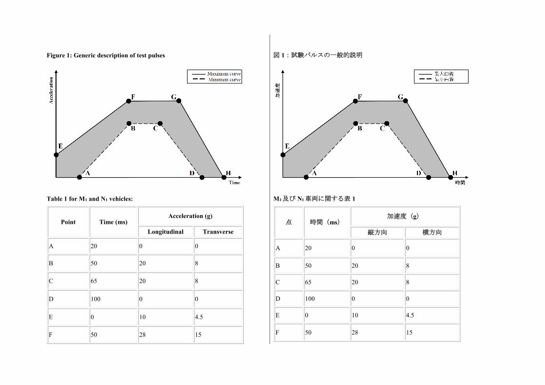
Figure 1: Generic description of test pulses
図 1:試験パルスの一般的説明
Table 1 for M1 and N1 vehicles:
Point Time (ms) Acceleration (g)
Longitudinal Transverse
A 20 0 0
B 50 20 8
C 65 20 8
D 100 0 0
E 0 10 4.5
F 50 28 15
M1及び N1車両に関する表 1
点 時間(ms) 加速度(g)
縦方向 横方向
A 20 0 0
B 50 20 8
C 65 20 8
D 100 0 0
E 0 10 4.5
F 50 28 15
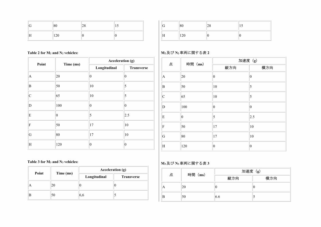
G 80 28 15
H 120 0 0
Table 2 for M2 and N2 vehicles:
Point Time (ms) Acceleration (g)
Longitudinal Transverse
A 20 0 0
B 50 10 5
C 65 10 5
D 100 0 0
E 0 5 2.5
F 50 17 10
G 80 17 10
H 120 0 0
Table 3 for M3 and N3 vehicles:
Point Time (ms) Acceleration (g)
Longitudinal Transverse
A 20 0 0
B 50 6,6 5
G 80 28 15
H 120 0 0
M2及び N2車両に関する表 2
点 時間(ms) 加速度(g)
縦方向 横方向
A 20 0 0
B 50 10 5
C 65 10 5
D 100 0 0
E 0 5 2.5
F 50 17 10
G 80 17 10
H 120 0 0
M3及び N3車両に関する表 3
点 時間(ms) 加速度(g)
縦方向 横方向
A 20 0 0
B 50 6.6 5
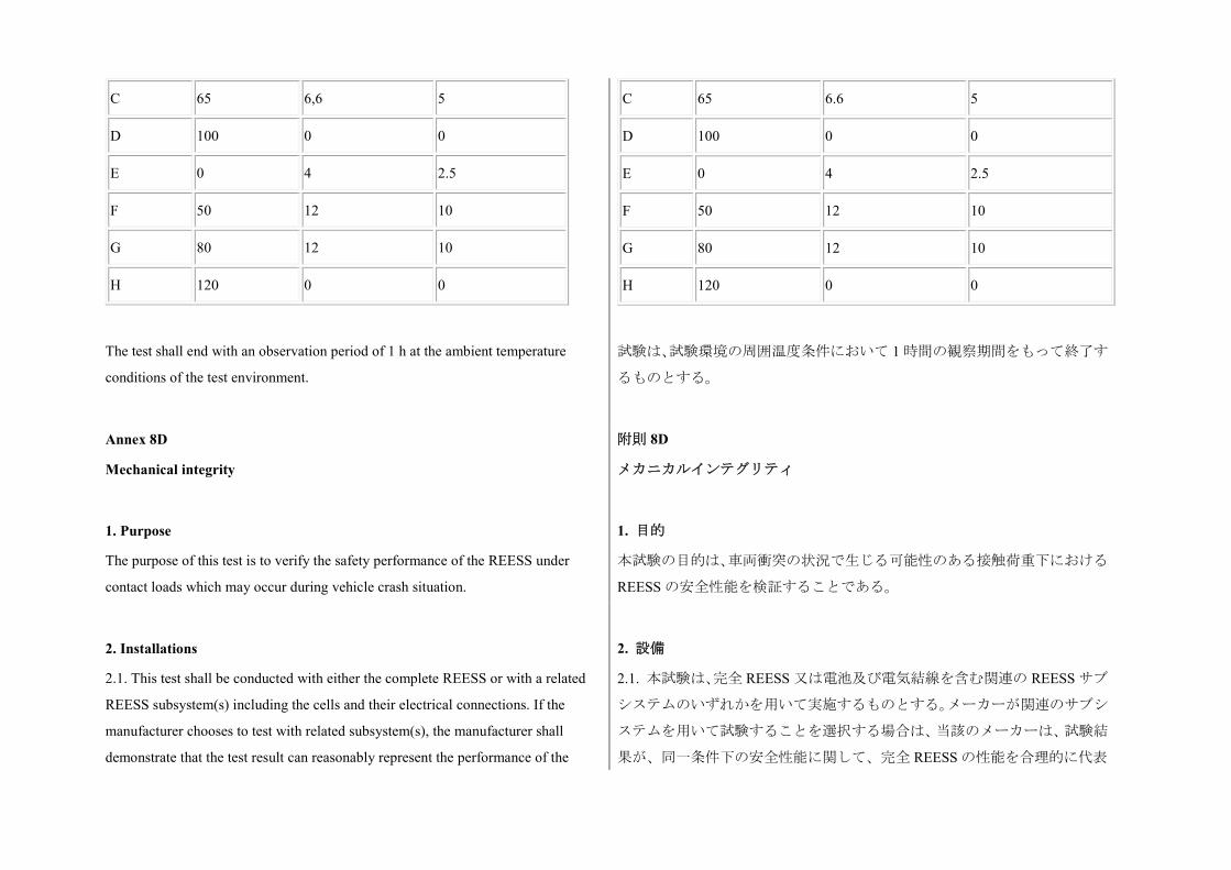
C 65 6,6 5
D 100 0 0
E 0 4 2.5
F 50 12 10
G 80 12 10
H 120 0 0
The test shall end with an observation period of 1 h at the ambient temperature
conditions of the test environment.
C 65 6.6 5
D 100 0 0
E 0 4 2.5
F 50 12 10
G 80 12 10
H 120 0 0
試験は、試験環境の周囲温度条件において 1 時間の観察期間をもって終了す
るものとする。
Annex 8D
Mechanical integrity
附則 8D
メカニカルインテグリティ
1. Purpose
The purpose of this test is to verify the safety performance of the REESS under
contact loads which may occur during vehicle crash situation.
1. 目的
本試験の目的は、車両衝突の状況で生じる可能性のある接触荷重下における
REESS の安全性能を検証することである。
2. Installations
2.1. This test shall be conducted with either the complete REESS or with a related
REESS subsystem(s) including the cells and their electrical connections. If the
manufacturer chooses to test with related subsystem(s), the manufacturer shall
demonstrate that the test result can reasonably represent the performance of the
2. 設備
2.1. 本試験は、完全 REESS 又は電池及び電気結線を含む関連の REESS サブ
システムのいずれかを用いて実施するものとする。メーカーが関連のサブシ
ステムを用いて試験することを選択する場合は、当該のメーカーは、試験結
果が、同一条件下の安全性能に関して、完全 REESS の性能を合理的に代表
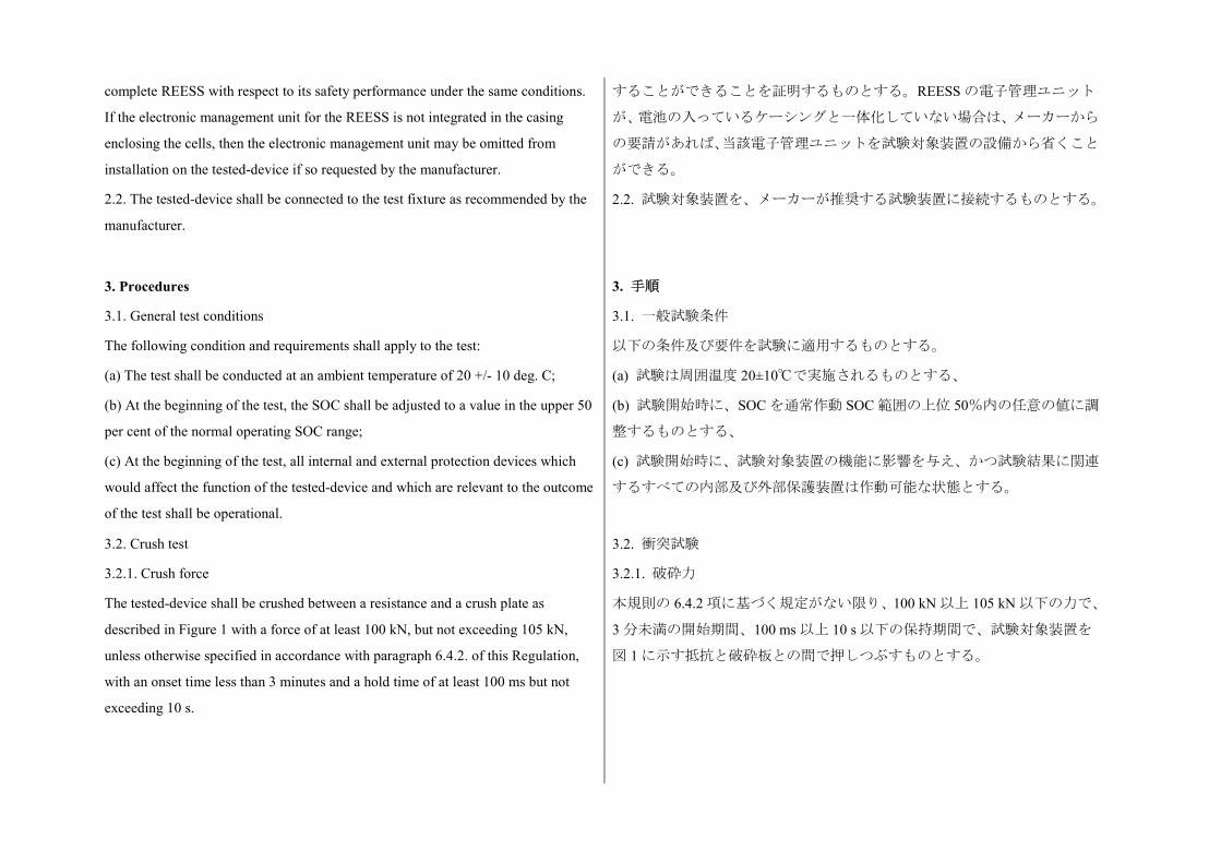
complete REESS with respect to its safety performance under the same conditions.
If the electronic management unit for the REESS is not integrated in the casing
enclosing the cells, then the electronic management unit may be omitted from
installation on the tested-device if so requested by the manufacturer.
2.2. The tested-device shall be connected to the test fixture as recommended by the
manufacturer.
することができることを証明するものとする。REESS の電子管理ユニット
が、電池の入っているケーシングと一体化していない場合は、メーカーから
の要請があれば、当該電子管理ユニットを試験対象装置の設備から省くこと
ができる。
2.2. 試験対象装置を、メーカーが推奨する試験装置に接続するものとする。
3. Procedures
3.1. General test conditions
The following condition and requirements shall apply to the test:
(a) The test shall be conducted at an ambient temperature of 20 +/- 10 deg. C;
(b) At the beginning of the test, the SOC shall be adjusted to a value in the upper 50
per cent of the normal operating SOC range;
(c) At the beginning of the test, all internal and external protection devices which
would affect the function of the tested-device and which are relevant to the outcome
of the test shall be operational.
3. 手順
3.1. 一般試験条件
以下の条件及び要件を試験に適用するものとする。
(a) 試験は周囲温度 20±10℃で実施されるものとする、
(b) 試験開始時に、SOC を通常作動 SOC 範囲の上位 50%内の任意の値に調
整するものとする、
(c) 試験開始時に、試験対象装置の機能に影響を与え、かつ試験結果に関連
するすべての内部及び外部保護装置は作動可能な状態とする。
3.2. Crush test
3.2.1. Crush force
The tested-device shall be crushed between a resistance and a crush plate as
described in Figure 1 with a force of at least 100 kN, but not exceeding 105 kN,
unless otherwise specified in accordance with paragraph 6.4.2. of this Regulation,
with an onset time less than 3 minutes and a hold time of at least 100 ms but not
exceeding 10 s.
3.2. 衝突試験
3.2.1. 破砕力
本規則の 6.4.2 項に基づく規定がない限り、100 kN 以上 105 kN 以下の力で、
3 分未満の開始期間、100 ms 以上 10 s 以下の保持期間で、試験対象装置を
図 1 に示す抵抗と破砕板との間で押しつぶすものとする。
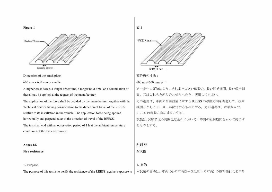
Figure 1
Dimension of the crush plate:
600 mm x 600 mm or smaller
A higher crush force, a longer onset time, a longer hold time, or a combination of
these, may be applied at the request of the manufacturer.
The application of the force shall be decided by the manufacturer together with the
Technical Service having consideration to the direction of travel of the REESS
relative to its installation in the vehicle. The application force being applied
horizontally and perpendicular to the direction of travel of the REESS.
The test shall end with an observation period of 1 h at the ambient temperature
conditions of the test environment.
図 1
破砕板の寸法:
600 mm×600 mm 以下
メーカーの要請により、それより大きい破砕力、長い開始期間、長い保持期
間、又はこれらを組み合わせたものを、適用してもよい。
力の適用は、車両の当該設備に対する REESS の移動方向を考慮して、技術
機関とともにメーカーが決定するものとする。力の適用は、水平方向で、
REESS の移動方向に垂直とする。
試験は、試験環境の周囲温度条件において 1 時間の観察期間をもって終了す
るものとする。
Annex 8E
Fire resistance
附則 8E
耐火性
1. Purpose
The purpose of this test is to verify the resistance of the REESS, against exposure to
1. 目的
本試験の目的は、車両(その車両自体又は近くの車両)の燃料漏れなど車外
fire from outside of the vehicle due to e.g. a fuel spill from a vehicle (either the
vehicle itself or a nearby vehicle). This situation should leave the driver and
passengers with enough time to evacuate.
からの火炎への曝露に対する REESS の耐性を検証することである。このよ
うな状況においては、運転者と乗員が避難するのに十分な時間が残されてい
るべきものである。
2. Installations
2.1. This test shall be conducted either with the complete REESS or with related
REESS subsystem(s) including the cells and their electrical connections. If the
manufacturer chooses to test with related subsystem(s), the manufacturer shall
demonstrate that the test result can reasonably represent the performance of the
complete REESS with respect to its safety performance under the same conditions.
If the electronic management unit for the REESS is not integrated in the casing
enclosing the cells, then the electronic management unit may be omitted from
installation on the tested-device if so requested by the manufacturer. Where the
relevant REESS subsystems are distributed throughout the vehicle, the test may be
conducted on each relevant of the REESS subsystem.
2. 設備
2.1. 本試験は、完全 REESS 又は電池及び電気結線を含む関連の REESS サブ
システムのいずれかを用いて実施するものとする。メーカーが関連のサブシ
ステムを用いて試験することを選択する場合は、当該のメーカーは、試験結
果が、同一条件下の安全性能に関して、完全 REESS の性能を合理的に代表
することができることを証明するものとする。REESS の電子管理ユニット
が、電池の入っているケーシングと一体化していない場合は、メーカーから
の要請があれば、当該電子管理ユニットを試験対象装置の設備から省くこと
ができる。関連の REESS サブシステムが車両全体に分散している場合は、
関連する各 REESS サブシステムについて試験を実施してもよい。
3. Procedures
3.1. General test conditions
The following requirements and conditions shall apply to the test:
(a) The test shall be conducted at a temperature of at least 0 deg. C;
(b) At the beginning of the test, the SOC shall be adjusted to a value in the upper 50
per cent of the normal operating SOC range;
(c) At the beginning of the test, all protection devices which effect the function of
the tested-device and are relevant for the outcome of the test shall be operational.
3. 手順
3.1. 一般試験条件
以下の要件及び条件を試験に適用するものとする。
(a) 試験は少なくとも温度 0℃で実施されるものとする、
(b) 試験開始時に、SOC は通常作動 SOC 範囲の上位 50%内の任意の値に調
整するものとする、
(c) 試験開始時に、試験対象装置の機能に影響を与え、かつ試験の結果に関
連するすべての保護装置は作動可能な状態とする。
3.2. Test procedure 3.2. 試験手順
A vehicle based test or a component based test shall be performed at the discretion
of the manufacturer:
メーカーの裁量により、車両に基づく試験又は構成部品に基づく試験を実施
するものとする。
3.2.1. Vehicle based test
The tested-device shall be mounted in a testing fixture simulating actual mounting
conditions as far as possible; no combustible material should be used for this with
the exception of material that is part of the REESS. The method whereby the
tested-device is fixed in the fixture shall correspond to the relevant specifications for
its installation in a vehicle. In the case of a REESS designed for a specific vehicle
use, vehicle parts which affect the course of the fire in any way shall be taken into
consideration.
3.2.1. 車両に基づく試験
できる限り実際の取り付け条件を再現するように、試験対象装置を試験装置
に取り付けるものとする。これには、REESS の一部である材料を除き、可
燃性材料を使うべきではないものとする。試験対象装置を装置に固定する方
法は、車両への取り付けに該当する仕様に対応するものとする。特定の車両
使用用に設計された REESS の場合は、何らかの形で火炎経路に影響を及ぼ
す車両部品を考慮に入れるものとする。
3.2.2. Component based test
The tested-device shall be placed on a grating table positioned above the pan, in an
orientation according to the manufacturer's design intent.
The grating table shall be constructed by steel rods, diameter 6-10 mm, with 4-6 cm
in between. If needed the steel rods could be supported by flat steel parts.
3.2.2. 構成部品に基づく試験
試験対象装置を、メーカーの設計意図に従った方向で、パンの上方に配置し
た格子テーブル上に置くものとする。
格子テーブルは、直径 6 から 10 mm で、4 から 6 cm の間隔をあけた鋼棒で
構成されるものとする。必要な場合は、鋼棒を平坦な鋼製部品で支えること
ができる。
3.3. The flame to which the tested-device is exposed shall be obtained by burning
commercial fuel for positive-ignition engines (hereafter called "fuel") in a pan. The
quantity of fuel shall be sufficient to permit the flame, under free-burning
conditions, to burn for the whole test procedure.
The fire shall cover the whole area of the pan during whole fire exposure. The pan
dimensions shall be chosen so as to ensure that the sides of the tested-device are
exposed to the flame. The pan shall therefore exceed the horizontal projection of the
tested-device by at least 20 cm, but not more than 50 cm. The sidewalls of the pan
shall not project more than 8 cm above the level of the fuel at the start of the test.
3.3. 試験対象装置を曝露させる炎は、強制点火エンジン用の市販燃料(以下
「燃料」と言う)をパンの中で燃焼させて得るものとする。燃料の量は、自
由燃焼条件下で、試験手順全体にわたって炎が燃焼するのに十分なものとす
る。
火炎は、火炎曝露の全期間中、パンの全面を覆うものとする。パンの寸法は、
試験対象装置の側面が炎に曝露されるように選ぶものとする。したがって、
パンは、試験対象装置の水平突起部分を 20 cm 以上 50 cm 以下上回るものと
する。パンの側壁は、試験開始時の燃料レベルの上方 8 cm を超えて突き出
ないものとする。
3.4. The pan filled with fuel shall be placed under the tested-device in such a way
that the distance between the level of the fuel in the pan and the bottom of the
tested-device corresponds to the design height of the tested-device above the road
surface at the unladen mass if paragraph 3.2.1. above is applied or approximately 50
cm if paragraph 3.2.2. above is applied. Either the pan, or the testing fixture, or
both, shall be freely movable.
3.4. パンの燃料レベルと試験対象装置の底部との距離が、上記 3.2.1 項を適
用する場合には無積載質量における試験対象装置の路面からの設計高さ相
当に、上記 3.2.2 項を適用する場合には約 50 cm になるようにして、燃料を
満たしたパンを試験対象装置の下に置くものとする。パン又は試験装置のい
ずれか、又はその両方が、自由に移動できる状態であるものとする。
3.5. During phase C of the test, the pan shall be covered by a screen. The screen
shall be placed 3 cm +/- 1 cm above the fuel level measured prior to the ignition of
the fuel. The screen shall be made of a refractory material, as prescribed in Annex
8E - Appendix 1. There shall be no gap between the bricks and they shall be
supported over the fuel pan in such a manner that the holes in the bricks are not
obstructed. The length and width of the frame shall be 2 cm to 4 cm smaller than the
interior dimensions of the pan so that a gap of 1 cm to 2 cm exists between the
frame and the wall of the pan to allow ventilation. Before the test the screen shall be
at least at the ambient temperature. The firebricks may be wetted in order to
guarantee repeatable test conditions.
3.5. 試験の段階 C 中、パンをスクリーンで覆うものとする。スクリーンは、
燃料点火前に測定した燃料レベルから 3cm±1cm 上に置くものとする。スク
リーンは、附則 8E − 付録 1 に規定した耐熱材料製とする。れんがの間には
隙間がないものとし、れんがの穴がふさがれないようにして、燃料パンの上
でれんがを支えるものとする。炎の長さ及び幅は、換気用に炎とパンの壁と
の間に 1 cm から 2 cm の隙間ができるように、パンの内部寸法より 2 cm か
ら 4 cm 小さいものとする。試験前に、スクリーンを少なくとも周囲温度に
置くものとする。耐火レンガは、再現性のある試験条件を保証するために、
濡らしてもよい。
3.6. If the tests are carried out in the open air, sufficient wind protection shall be
provided and the wind velocity at pan level shall not exceed 2.5 km/h.
3.6. 試験を屋外で実施する場合は、十分な風防を備えるものとし、パンレベ
ルにおける風速は 2.5 km/h を超えないものとする。
3.7. The test shall comprise of three phases B-D, if the fuel is at least at temperature
of 20 deg. C. Otherwise the test shall comprise four phases A-D.
3.7. 燃料が少なくとも 20℃の温度の場合は、試験は B から D の 3 つの段階
で構成するものとする。それ以外の場合は、試験は、A から D の 4 つの段
階で構成するものとする。
3.7.1. Phase A: Pre-heating (Figure 1)
The fuel in the pan shall be ignited at a distance of at least 3 m from the
tested-device. After 60 seconds pre-heating, the pan shall be placed under the
tested-device. If the size of the pan is too large to be moved without risking liquid
spills etc. then the tested-device and test rig can be moved over the pan instead.
3.7.1. 段階 A:予熱(図 1)
試験対象装置から少なくとも 3 m の距離で、パン内の燃料を点火するものと
する。60 秒間の予熱後、パンを試験対象装置の下に置くものとする。パン
のサイズが大きすぎて液体漏れなどのリスクがあるために移動できない場
合は、代わりに試験対象装置と試験リグをパンのところに移動することがで
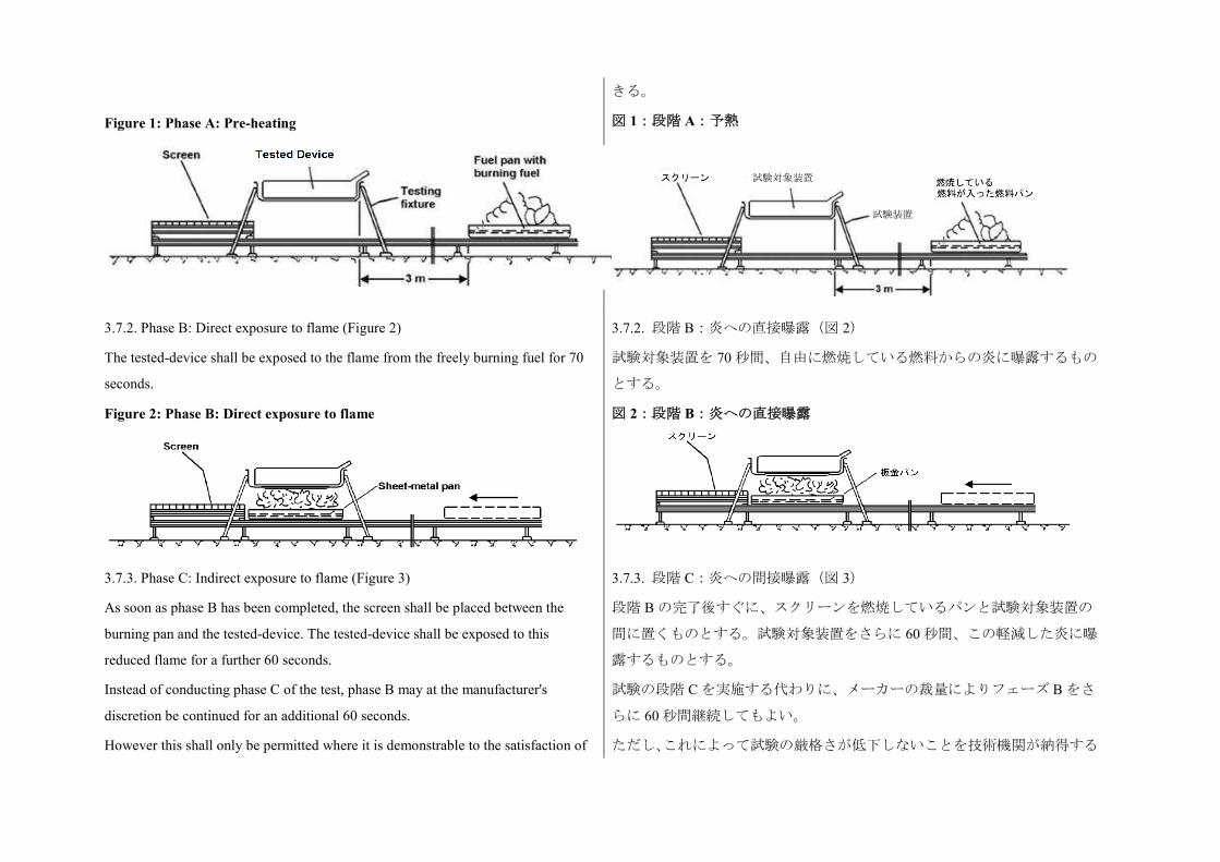
Figure 1: Phase A: Pre-heating
きる。
図 1:段階 A:予熱
3.7.2. Phase B: Direct exposure to flame (Figure 2)
The tested-device shall be exposed to the flame from the freely burning fuel for 70
seconds.
Figure 2: Phase B: Direct exposure to flame
3.7.2. 段階 B:炎への直接曝露(図 2)
試験対象装置を 70 秒間、自由に燃焼している燃料からの炎に曝露するもの
とする。
図 2:段階 B:炎への直接曝露
3.7.3. Phase C: Indirect exposure to flame (Figure 3)
As soon as phase B has been completed, the screen shall be placed between the
burning pan and the tested-device. The tested-device shall be exposed to this
reduced flame for a further 60 seconds.
Instead of conducting phase C of the test, phase B may at the manufacturer's
discretion be continued for an additional 60 seconds.
However this shall only be permitted where it is demonstrable to the satisfaction of
3.7.3. 段階 C:炎への間接曝露(図 3)
段階 B の完了後すぐに、スクリーンを燃焼しているパンと試験対象装置の
間に置くものとする。試験対象装置をさらに 60 秒間、この軽減した炎に曝
露するものとする。
試験の段階 C を実施する代わりに、メーカーの裁量によりフェーズ B をさ
らに 60 秒間継続してもよい。
ただし、これによって試験の厳格さが低下しないことを技術機関が納得する
試験対象装置
試験装置
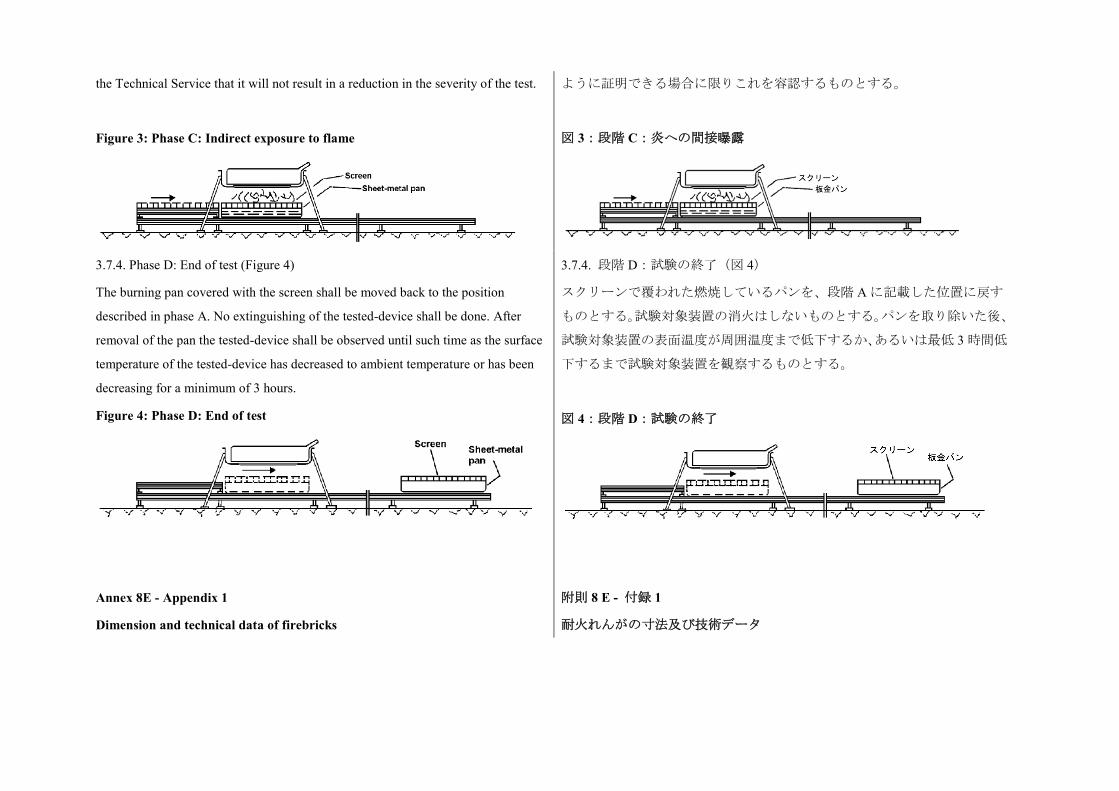
the Technical Service that it will not result in a reduction in the severity of the test.
Figure 3: Phase C: Indirect exposure to flame
ように証明できる場合に限りこれを容認するものとする。
図 3:段階 C:炎への間接曝露
3.7.4. Phase D: End of test (Figure 4)
The burning pan covered with the screen shall be moved back to the position
described in phase A. No extinguishing of the tested-device shall be done. After
removal of the pan the tested-device shall be observed until such time as the surface
temperature of the tested-device has decreased to ambient temperature or has been
decreasing for a minimum of 3 hours.
Figure 4: Phase D: End of test
3.7.4. 段階 D:試験の終了(図 4)
スクリーンで覆われた燃焼しているパンを、段階 A に記載した位置に戻す
ものとする。試験対象装置の消火はしないものとする。パンを取り除いた後、
試験対象装置の表面温度が周囲温度まで低下するか、あるいは最低 3 時間低
下するまで試験対象装置を観察するものとする。
図 4:段階 D:試験の終了
Annex 8E - Appendix 1
Dimension and technical data of firebricks
附則 8 E - 付録 1
耐火れんがの寸法及び技術データ
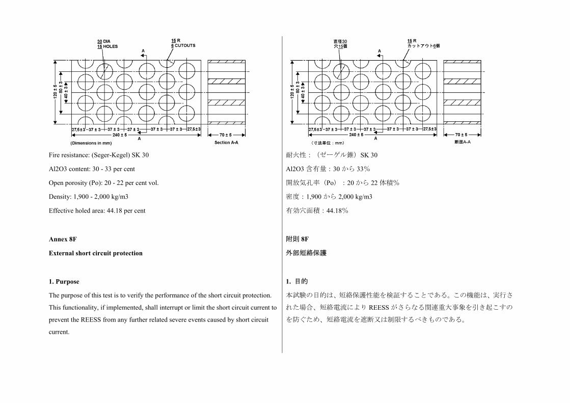
Fire resistance: (Seger-Kegel) SK 30
Al2O3 content: 30 - 33 per cent
Open porosity (Po): 20 - 22 per cent vol.
Density: 1,900 - 2,000 kg/m3
Effective holed area: 44.18 per cent
耐火性:(ゼーゲル錐)SK 30
Al2O3 含有量:30 から 33%
開放気孔率(Po):20 から 22 体積%
密度:1,900 から 2,000 kg/m3
有効穴面積:44.18%
Annex 8F
External short circuit protection
附則 8F
外部短絡保護
1. Purpose
The purpose of this test is to verify the performance of the short circuit protection.
This functionality, if implemented, shall interrupt or limit the short circuit current to
prevent the REESS from any further related severe events caused by short circuit
current.
1. 目的
本試験の目的は、短絡保護性能を検証することである。この機能は、実行さ
れた場合、短絡電流により REESS がさらなる関連重大事象を引き起こすの
を防ぐため、短絡電流を遮断又は制限するべきものである。
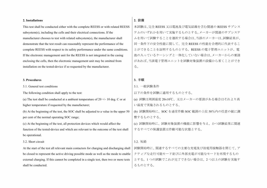
2. Installations
This test shall be conducted either with the complete REESS or with related REESS
subsystem(s), including the cells and their electrical connections. If the
manufacturer chooses to test with related subsystem(s), the manufacturer shall
demonstrate that the test result can reasonably represent the performance of the
complete REESS with respect to its safety performance under the same conditions.
If the electronic management unit for the REESS is not integrated in the casing
enclosing the cells, then the electronic management unit may be omitted from
installation on the tested-device if so requested by the manufacturer.
2. 設備
本試験は、完全 REESS 又は電池及び電気結線を含む関連の REESS サブシス
テムのいずれかを用いて実施するものとする。メーカーが関連のサブシステ
ムを用いて試験することを選択する場合は、当該のメーカーは、試験結果が、
同一条件下の安全性能に関して、完全 REESS の性能を合理的に代表するこ
とができることを証明するものとする。REESS の電子管理ユニットが、電
池の入っているケーシングと一体化していない場合は、メーカーからの要請
があれば、当該電子管理ユニットを試験対象装置の設備から省くことができ
る。
3. Procedures
3.1. General test conditions
The following condition shall apply to the test:
(a) The test shall be conducted at a ambient temperature of 20 +/- 10 deg. C or at
higher temperature if requested by the manufacturer;
(b) At the beginning of the test, the SOC shall be adjusted to a value in the upper 50
per cent of the normal operating SOC range;
(c) At the beginning of the test, all protection devices which would affect the
function of the tested-device and which are relevant to the outcome of the test shall
be operational.
3. 手順
3.1. 一般試験条件
以下の条件を試験に適用するものとする。
(a) 試験は周囲温度 20±10℃、又はメーカーの要請がある場合はそれより高
い温度で実施されるものとする、
(b) 試験開始時に、SOC を通常作動 SOC 範囲の上位 50%内の任意の値に調
整するものとする、
(c) 試験開始時に、試験対象装置の機能に影響を与え、かつ試験結果に関連
するすべての保護装置は作動可能な状態とする。
3.2. Short circuit
At the start of the test all relevant main contactors for charging and discharging shall
be closed to represent the active driving possible mode as well as the mode to enable
external charging. If this cannot be completed in a single test, then two or more tests
shall be conducted.
3.2. 短絡
試験開始時に、関連するすべての主要な充電及び放電用接触器を閉じて、ア
クティブな走行可能モード並びに外部充電が可能なモードを再現するもの
とする。1 つの試験でこれが完了できない場合は、2 つ以上の試験を実施す
るものとする。
The positive and negative terminals of the tested-device shall be connected to each
other to produce a short circuit. The connection used for this purpose shall have a
resistance not exceeding 5 megohms.
The short circuit condition shall be continued until the operation of the REESS's
protection function to interrupt or limit the short circuit current is confirmed, or for
at least one hour after the temperature measured on the casing of the tested-device
has stabilised, such that the temperature gradient varies by a less than 4 deg. C
through 1 hour.
試験対象装置の正及び負の端子を相互に接続して短絡を形成するものとす
る。この目的で使用する接続の抵抗は 5 mΩ を超えないものとする。
短絡電流を遮断又は制限する REESS の保護機能の作動が確認されるまで、
あるいは試験対象装置のケーシング上で測定した温度が安定してから、温度
勾配の変動が 1 時間で 4℃未満になるように少なくとも 1 時間は短絡条件を
継続するものとする。
3.3. Standard cycle and observation period
Directly after the termination of the short circuit a standard cycle as described in
Annex 8, Appendix 1 shall be conducted, if not inhibited by the tested-device.
The test shall end with an observation period of 1 h at the ambient temperature
conditions of the test environment.
3.3. 標準サイクル及び観察期間
短絡停止直後、試験対象装置によって阻害されない場合は、附則 8 の付録 1
に記載した標準サイクルを実施するものとする。
試験は、試験環境の周囲温度条件において 1 時間の観察期間をもって終了す
るものとする。
Annex 8G
Overcharge protection
附則 8G
過充電保護
1. Purpose
The purpose of this test is to verify the performance of the overcharge protection.
1. 目的
本試験の目的は、過充電保護性能を検証することである。
2. Installations
This test shall be conducted, under standard operating conditions, either with the
complete REESS (this maybe a complete vehicle) or with related REESS
subsystem(s), including the cells and their electrical connections. If the
2. 設備
本試験は、標準作動条件下で、完全 REESS(おそらく完全車両)又は電池
及び電気結線を含む関連の REESS サブシステムのいずれかを用いて実施す
るものとする。メーカーが関連のサブシステムを用いて試験することを選択
manufacturer chooses to test with related subsystem(s), the manufacturer shall
demonstrate that the test result can reasonably represent the performance of the
complete REESS with respect to its safety performance under the same conditions.
The test may be performed with a modified tested-device as agreed by the
manufacturer and the Technical Service. These modifications shall not influence the
test results.
する場合は、当該のメーカーは、試験結果が、同一条件下の安全性能に関し
て、完全 REESS の性能を合理的に代表することができることを証明するも
のとする。
試験は、メーカーと技術機関が合意した変更済み試験対象装置を用いて実施
してもよい。かかる変更は試験結果に影響を与えないものとする。
3. Procedures
3.1. General test conditions
The following requirements and conditions shall apply to the test:
(a) The test shall be conducted at an ambient temperature of 20 +/- 10 deg. C or at
higher temperature if requested by the manufacturer;
(b) At the beginning of the test, all protection devices which would affect the
function of the tested-device and which are relevant to the outcome of the test shall
be operational.
3. 手順
3.1. 一般試験条件
以下の要件及び条件を試験に適用するものとする。
(a) 試験を周囲温度 20±10℃、又はメーカーの要請がある場合はそれより高
い温度で実施するものとする、
(b) 試験開始時に、試験対象装置の機能に影響を与え、かつ試験結果に関連
するすべての保護装置は作動可能な状態とする。
3.2. Charging
At the beginning all relevant main contactors for charging shall be closed.
The charge control limits of the test equipment shall be disabled.
The tested-device shall be charged with a charge current of at least 1/3C rate but not
exceeding the maximum current within the normal operating range as specified by
the manufacturer.
The charging shall be continued until the tested-device (automatically) interrupts or
limits the charging. Where an automatic interrupt function fails to operate, or if
there is no such function the charging shall be continued until the tested-device is
charged to twice of its rated charge capacity.
3.2. 充電
開始時に、すべての関連する主要な充電用接触器を閉じるものとする。
試験装置の充電制御限界を無効にするものとする。
少なくとも 1/3 C 率、かつメーカーが規定した通常作動範囲内の最大電流を
超えない充電電流で試験対象装置を充電するものとする。
試験対象装置が(自動的に)充電を中断又は制限するまで充電を継続するも
のとする。自動中断機能が作動しない場合、又はかかる機能がない場合は、
試験対象装置がその定格充電容量の 2 倍まで充電されるまで、充電を継続す
るものとする。
3.3. Standard cycle and observation period
Directly after the termination of charging a standard cycle as described in Annex 8,
Appendix 1 shall be conducted, if not inhibited by the tested-device.
The test shall end with an observation period of 1 h at the ambient temperature
conditions of the test environment.
3.3. 標準サイクル及び観察期間
充電停止直後、試験対象装置によって阻害されない場合は、附則 8 の付録 1
に記載した標準サイクルを実施するものとする。
試験は、試験環境の周囲温度条件において 1 時間の観察期間をもって終了す
るものとする。
Annex 8H
Over-discharge protection
附則 8H
過放電保護
1. Purpose
The purpose of this test is to verify the performance of the over-discharge
protection. This functionality, if implemented, shall interrupt or limit the discharge
current to prevent the REESS from any severe events caused by a too low SOC as
specified by the manufacturer.
1. 目的
本試験の目的は、過放電保護性能を検証することである。この機能は、実施
された場合、メーカーが規定した低すぎる SOC によって REESS が重大事象
になるのを防ぐために、放電電流を遮断又は制限するものとする。
2. Installations
This test shall be conducted, under standard operating conditions, either with the
complete REESS (this maybe a complete vehicle) or with related REESS
subsystem(s), including the cells and their electrical connections. If the
manufacturer chooses to test with related subsystem(s), the manufacturer shall
demonstrate that the test result can reasonably represent the performance of the
complete REESS with respect to its safety performance under the same conditions.
The test may be performed with a modified tested-device as agreed by the
manufacturer and the Technical Service. These modifications shall not influence the
test results.
2. 設備
本試験は、標準作動条件下で、完全 REESS(おそらく完全車両)又は電池
及び電気結線を含む関連の REESS サブシステムのいずれかを用いて実施す
るものとする。メーカーが関連のサブシステムを用いて試験することを選択
する場合は、当該のメーカーは、試験結果が、同一条件下の安全性能に関し
て、完全 REESS の性能を合理的に代表することができることを証明するも
のとする。
試験は、メーカーと技術機関が合意した変更済み試験対象装置を用いて実施
してもよい。かかる変更は試験結果に影響を与えないものとする。
3. Procedures
3.1. General test conditions
The following requirements and condition shall apply to the test:
(a) The test shall be conducted at an ambient temperature of 20 +/- 10 deg. C or at
higher temperature if requested by the manufacturer;
(b) At the beginning of the test, all protection devices which would affect the
function of the tested-device and which are relevant for the outcome of the test shall
be operational.
3. 手順
3.1. 一般試験条件
以下の要件及び条件を試験に適用するものとする。
(a) 試験を周囲温度 20±10℃、又はメーカーの要請がある場合はそれより高
い温度で実施するものとする、
(b) 試験開始時に、試験対象装置の機能に影響を与え、かつ試験結果に関連
するすべての保護装置は作動可能な状態とする。
3.2. Discharging
At the beginning of the test, all relevant main contactors shall be closed.
A discharge shall be performed with at least 1/3 C rate but shall not exceed the
maximum current within the normal operating range as specified by the
manufacturer.
The discharging shall be continued until the tested-device (automatically) interrupts
or limits the discharging. Where an automatic interrupt function fails to operate, or
if there is no such function then the discharging shall be continued until the
tested-device is discharged to 25 per cent of its nominal voltage level.
3.2. 放電
試験開始時に、すべての関連する主要な接触器を閉じるものとする。
少なくとも 1/3 C 率で放電を実施するものとするが、メーカーが規定した通
常作動範囲内の最大電流を超えないものとする。
試験対象装置が(自動的に)放電を中断又は制限するまで放電を継続するも
のとする。自動中断機能が作動しない場合、又はかかる機能がない場合は、
試験対象装置が公称電圧レベルの 25%になるまで放電するまで放電を継続
するものとする。
3.3. Standard charge and observation period
Directly after termination of the discharging the tested-device shall be charged with
a standard charge as specified in Annex 8, Appendix 1 if not inhibited by the
tested-device.
The test shall end with an observation period of 1 h at the ambient temperature
conditions of the test environment.
3.3. 標準充電及び観察期間
試験対象装置の放電停止直後、試験対象装置によって阻害されない場合は、
附則 8 の付録 1 に記載した標準充電で試験対象装置を充電するものとする。
試験は、試験環境の周囲温度条件において 1 時間の観察期間をもって終了す
るものとする。
Annex 8I
Over-temperature protection
附則 8I
過昇温保護
1. Purpose
The purpose of this test is to verify the performance of the protection measures of
the REESS against internal overheating during the operation, even under the failure
of the cooling function if applicable. In the case that no specific protection measures
are necessary to prevent the REESS from reaching an unsafe state due to internal
over-temperature, this safe operation must be demonstrated.
1. 目的
本試験の目的は、冷却機能が故障した場合においても(該当する場合)、作
動中の内部過熱に対する REESS の保護措置の性能を検証することである。
内部過昇温によって REESS が不安全な状態になるのを防ぐために特定の保
護措置が必要ない場合には、この安全な作動を証明しなければならない。
2. Installations
2.1. The following test may be conducted with the complete REESS (maybe as a
complete vehicle) or with related REESS subsystem(s), including the cells and their
electrical connections. If the manufacturer chooses to test with related subsystem(s),
the manufacturer shall demonstrate that the test result can reasonably represent the
performance of the complete REESS with respect to its safety performance under
the same conditions. The test may be performed with a modified tested-device as
agreed by the manufacturer and the Technical Service. These modifications shall not
influence the test results.
2. 設備
2.1. 以下の試験は、完全 REESS(おそらく完全車両として)又は電池及び
電気結線を含む関連の REESS サブシステムを用いて実施することができ
る。メーカーが関連のサブシステムを用いて試験することを選択する場合
は、当該のメーカーは、試験結果が、同一条件下の安全性能に関して、完全
REESS の性能を合理的に代表することができることを証明するものとす
る。試験は、メーカーと技術機関が合意した変更済み試験対象装置を用いて
実施してもよい。かかる変更は試験結果に影響を与えないものとする。
2.2. Where a REESS is fitted with a cooling function and where the REESS will
remain functional without a cooling function system being operational, the cooling
system shall be deactivated for the test.
2.2. REESS に冷却機能が備わっており、かつ冷却機能システムが作動可能な
状態でなくても REESS が引き続き機能する場合は、当該試験については冷
却システムを不作動にするものとする。
2.3. The temperature of the tested-device shall be continuously measured inside the
casing in the proximity of the cells during the test in order to monitor the changes of
2.3. 温度変化を監視するために、試験中、ケーシング内部の電池の近傍で、
試験対象装置の温度を継続的に測定するものとする。車載センサがある場合

the temperature. The onboard sensor if existing may be used. The manufacturer and
Technical Service shall agree on the location of the temperature sensor(s) used.
は使用してもよい。メーカーと技術機関は、使用する温度センサの位置につ
いて合意するものとする。
3. Procedures
3.1. At the beginning of the test, all protection devices which affect the function of
the tested-device and are relevant to the outcome of the test shall be operational,
except for any system deactivation implemented in accordance with paragraph 2.2.
above.
3. 手順
3.1. 試験開始時に、試験対象装置の機能に影響を与え、かつ試験結果に関連
するすべての保護装置は作動可能な状態とする。ただし、上記 2.2 項に従っ
て実施したシステムの不作動を除く。
3.2. During the test, the tested-device shall be continuously charged and discharged
with a steady current that will increase the temperature of cells as rapidly as possible
within the range of normal operation as defined by the manufacturer.
3.2. 試験中は、メーカーが規定する通常作動範囲内で、電池の温度をできる
だけ急速に上げる定常電流を使用し、試験対象装置を継続的に充電及び放電
するものとする。
3.3. The tested-device shall be placed in a convective oven or climatic chamber. The
temperature of the chamber or oven shall be gradually increased until it reaches the
temperature determined in accordance with paragraph 3.3.1. or 3.3.2. below as
applicable, and then maintained at a temperature that is equal to or higher than this,
until the end of the test.
3.3. 試験対象装置を対流式オーブン又は気候室に置くものとする。気候室又
はオーブンの温度を、下記 3.3.1 項又は 3.3.2 項の該当する方に従って定めた
温度に達するまで徐々に上げ、試験終了までこの温度と同等又はそれ以上の
温度に維持するものとする。
3.3.1. Where the REESS is equipped with protective measures against internal
overheating, the temperature shall be increased to the temperature defined by the
manufacturer as being the operational temperature threshold for such protective
measures, to insure that the temperature of the tested-device will increase as
specified in paragraph 3.2. above.
3.3.1. REESS が内部過熱に対する保護措置を備えている場合は、試験対象装
置の温度が上記項に定めた通り上昇することを保証するために、メーカーが
かかる保護措置に対する作動温度閾値として定めた温度まで温度を上げる
ものとする。
3.3.2. Where the REESS is not equipped with any specific measures against internal
over-heating, the temperature shall be increased to the maximum operational
temperature specified by the manufacturer.
3.3.2. REESS が内部過熱に対する特定の保護措置を備えていない場合は、メ
ーカーが規定する最高作動温度まで温度を上げるものとする。
3.4. The end of test: The test will end when one of the followings is observed: 3.4. 試験の終了:試験は以下の 1 つが観察された時点で終了する。
(a) The tested-device inhibits and/or limits the charge and/or discharge to prevent
the temperature increase;
(b) The temperature of the tested-device is stabilised, which means that the
temperature varies by a gradient of less than 4 deg. C through 2 hours;
(c) Any failure of the acceptance criteria prescribed in paragraph 6.9.2.1. of the
Regulation.
(a) 温度上昇を防ぐために、試験対象装置が充電又は放電を阻害又は制限す
る、
(b) 試験対象装置の温度が安定する。つまり、2 時間で 4℃未満の勾配で温
度が変化することを意味する、
(c) 本規則の 6.9.2.1 項に規定した合格基準を満たさない。