Embed Size (px)
Citation preview
Examensarbete, Högskolan på Åland, Utbildningsprogrammet för maskinteknik Undersökning av Vingsegel
Anordning för Robotsegelbåt
Enqvist Teo Johannes
Datum för publicering: 16.05.2016 Handledare: Florian Haug
1
EXAMENSARBETE Högskolan på Åland Utbildningsprogram: Maskinteknikprogrammet Författare: Teo Enqvist Arbetets namn: Undersökning av Vingsegel-anordning för robotsegelbåt Handledare: Florian Haug Uppdragsgivare: Anna Friebe / Åland Sailing Robots Abstrakt Arbetet har gjorts på begäran av Åland Sailing Robots (ÅSR) genom Anna Friebe. Syftet med arbetet är att undersöka olika vingsegelanordningar lämpliga för robotsegelbåten Mini 12:an som ägs av ÅSR. Den lämpligaste vingsegel-anordningen för Mini 12:an kommer att undersökas ytterligare med hjälp av CFD-simuleringsprogram. Arbetet innehåller lösningar och diskussion angående konstruktion av vingsegel-anordningen som ett framtida projekt. Genom att undersöka Mini 12:ans nuvarande segel och dess framdrivningsförmåga har en vingsegel anordning med liknande framdrivningsförmåga designats och ytterligare undersökts. Arbetet beskriver problem som kan förekomma under konstruktion av vingsegel-anordningen och erbjuder möjliga lösningar till dessa problem. Autodesk Simulation CFD 2016 har används för undersökningen av vingsegel-anordningens egenskaper i olika vindförhållanden och dessa resultat har i sin helhet överlämnats åt ÅSR. Detta arbete innehåller en sammanfattning av de väsentliga resultaten. Ritningar av vingsegelanordningen i fråga biläggs i arbetet. Nyckelord (sökord) Ving, segel, Vingsegel-anordning, Åland Sailing Robots, The Microtransat Challenge, Segelbåt, robot, CFD, simulering, Högskolans serienummer: ISSN: Språk: Sidantal: 05/2016 1458-1531 Engelska 61 sidor Inlämningsdatum: Presentationsdatum: Datum för
godkännande: 16.05.2016 13.05.2016 16.05.2016
2
DEGREE THESIS Åland University of Applied Sciences Study program: Marine Engineering Author: Teo Enqvist Title: Wingsail Arrangements for Robotic Sailboat Academic Supervisor: Florian Haug Technical Supervisor: Anna Friebe / Åland Sailing Robots Abstract This thesis has been done on request by the Åland Sailing Robots (ÅSR) and Anna Friebe. The purpose of the study is to examine different wing sails arrangements suitable for a robotic sailing boat, the Mini 12 owned by ÅSR. The most suitable wing sail arrangement for the Mini 12 was investigated further using CFD simulation software. The work also includes solutions and discussion on the construction of the wing sail device as a future project. By examining the Mini 12’s current sails and its propulsion capability, a wing sail arrangement with a similar propulsion capability has been designed and, investigated further. The work describes problems that may occur during the construction of the wing arrangement and provides possible solutions to these problems. Autodesk Simulation CFD 2016 has been used for the investigation of the wing arrangement and its properties in various wind conditions and these results have been handed to ÅSR. This work contains a summary of the essential results. Drawings of the wing sail device in question are provided as an annex. Key words Wing sail arrangement, Åland Sailing Robots, The Microtransat Challenge, sailboat, autonomous, CFD, simulation Serial number: ISSN: Language: Number of pages: 05/2016 1458-1531 English 61 Handed in: Date of presentation: Approved on: 16.05.2016 13.05.2016 16.05.2016
3
TABLE OF CONTENTS ................................................................................................................................................................. 4 1. Introduction ..................................................................................................................................... 5
1.1. Purpose ..................................................................................................................................... 5 1.2. Limitations in this Project .................................................................................................... 5
2. History ............................................................................................................................................... 6 2.1. A Brief History of Sailing and Aviation ............................................................................. 6
2.1.1. From the Skies to the Sea ............................................................................................. 6 2.2. The Microtransat Challenge ................................................................................................. 8
2.2.1. Mini 12 ................................................................................................................................ 8 3. Methods of wind assisted propulsion .................................................................................... 10
3.1. Conventional (soft) Sails .................................................................................................... 10 3.2. Mechanical Devices ............................................................................................................. 11
3.2.1. Flettner Rotors ............................................................................................................... 11 3.2.2. Vertical/Horizontal Axis Turbine ................................................................................ 12
4. Wingsails ........................................................................................................................................ 13 4.1. A Closer Look at the Wings ............................................................................................... 13
4.1.1. Single Wing ..................................................................................................................... 13 4.1.2. Tandem Wings ............................................................................................................... 14
4.2. Results and Summary of Wing Selection ....................................................................... 17 4.4. Theory and Reality and the Issues that Follow ............................................................ 19
5. Theory behind the wing .............................................................................................................. 20 5.1. Design Criteria of Wingsails .............................................................................................. 20 5.3. Apparent Wind ....................................................................................................................... 22 5.4. NACA Airfoils ......................................................................................................................... 22
5.4.1. Four-Digit Series ............................................................................................................ 23 5.4.2. Difference between Symmetric/Asymmetric Airfoils ........................................... 26
5.5. Reynolds Number ................................................................................................................. 27 5.5.1. Laminar Separation Bubble ........................................................................................ 28 5.5.2. Stalling ............................................................................................................................. 29 5.5.2.1. Leading Edge Stall ..................................................................................................... 30 5.5.2.2. Trailing Edge Stall ...................................................................................................... 30
6. The Wing for ÅSR Mini 12 .......................................................................................................... 31 6.1. Aside from Efficiency .......................................................................................................... 31
6.1.1. Economic Viability. ....................................................................................................... 31
4
6.1.2. Simplicity ......................................................................................................................... 32 6.1.3. Reliability ......................................................................................................................... 32 6.1.4. Autonomous Operationality ....................................................................................... 33 6.1.5. Design and Installation ................................................................................................ 33
6.2. A Self-Trimming Wing Arrangement ................................................................................ 34 6.3. Calculations Behind the Wing Design ............................................................................ 36
7. Simulations and CFD .................................................................................................................. 41 7.1. Computational Fluid Dynamics (CFD) ............................................................................. 41 7.2. Getting Started ...................................................................................................................... 42 7.2.1. Deciding the Airfoil ........................................................................................................... 42 7.2.2. Drawing Airfoils and Building the Simulation ........................................................... 43 7.3. Creating the Simulation ...................................................................................................... 44 7.4. Results from the CFD Simulations ................................................................................... 47 7.5 Discussion ............................................................................................................................... 48
8. Practical issues and solutions ................................................................................................. 49 8.1. Aerodynamic and Mass Center Alignment .................................................................... 49 8.2. Steering the Wing ................................................................................................................. 51
8.2.1. Electric/Hydraulic Steering ......................................................................................... 52 8.2.2. Mechanical Steering ..................................................................................................... 52
8.3. Materials .................................................................................................................................. 53 8.4 Conclusion............................................................................................................................... 54
9. Summary ........................................................................................................................................ 55 References ......................................................................................................................................... 56 Annex ................................................................................................................................................... 58
5
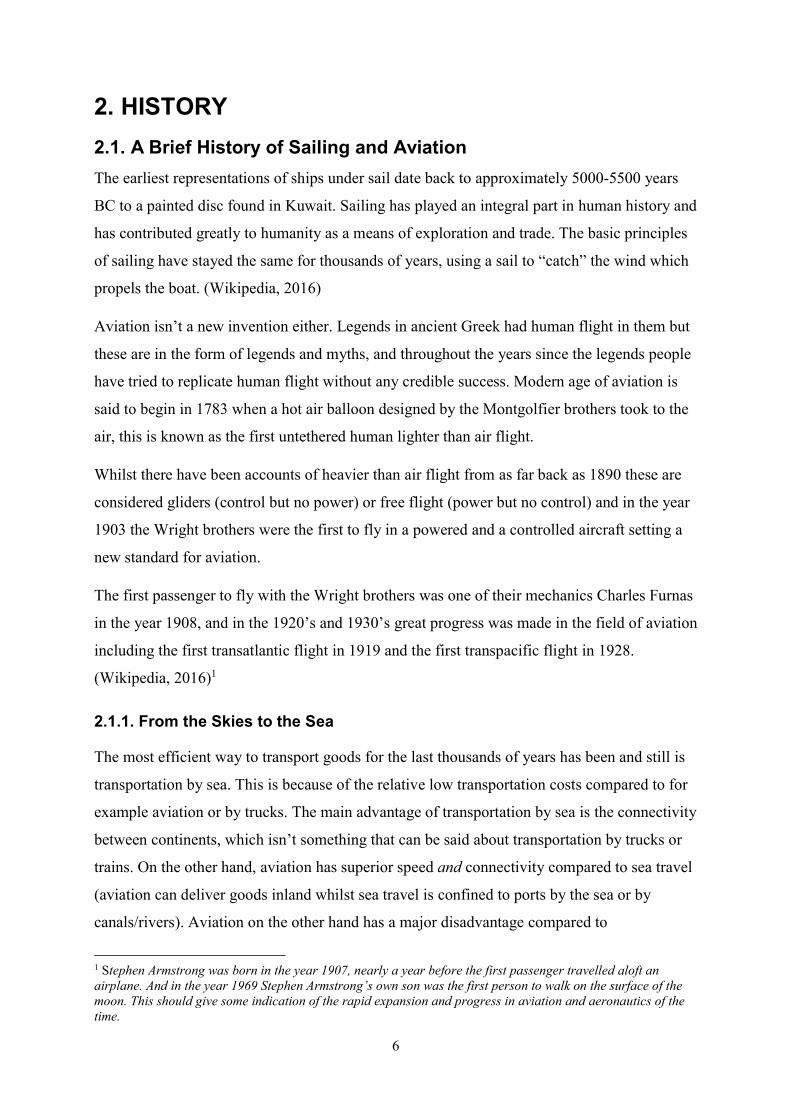
1. INTRODUCTION 1.1. Purpose The purpose of this thesis is to research the possibility of a wingsail arrangement aboard the autonomous sailing robot by Åland Sailing Robot (ÅSR) named Mini 12 and to come up with wingsail arrangements suitable for the Mini12. This includes discussion of various types of wind assisted propulsion and choosing the most suitable, researching that application, perform CFD simulations, develop drawings and come up with solutions for possible challenges that may arise with this project. I chose to write about this project because I think this is a fine blend between aviation and sailing theory, both of which I have very modest experience with, but a great interest in learning. Also being a part of a robotic sailing team that competes among the best in the world gives me motivation to research more efficient ways to propel the ÅSR Mini 12 to victory. Furthermore I see the potential of these autonomous sail boats in researching the oceans and that intrigues the adventurous side of me. The research possibilities of autonomous sail boats are vast because of the possibilities these boats are suitable for. For example, consider if someone would build a thousand of these boats equipped with a sonar system for mapping the ocean and sending them off to systematically map the ocean floor. Granted this would take a very long time to do but the autonomous ability would let these boats operate for possibly years without the need of human interaction. This is one of my personal future dreams. It is grand but by all means I believe it to be possible in the future but till then we must optimize the sailing robots and build a steady platform for the future to stand upon. The thought of being part of a team that in the future can be considered a pioneer in robotic sailing fuels my motivation for writing and researching a wingsail application. 1.2. Limitations in this Project Because this project is done by one individual the limitations are numerous. Because of the simple fact that time and the amount of work behind a project like this is extensive and some compromises must be made in order to finish this project in the time given. The biggest limitation is the fact that this project is purely theoretical and done for researching the possible wing arrangement. If time wasn’t an issue and more people would be a part of this project the constructing of the wing as a part of this project could have been a possibility.
6
2. HISTORY 2.1. A Brief History of Sailing and Aviation The earliest representations of ships under sail date back to approximately 5000-5500 years BC to a painted disc found in Kuwait. Sailing has played an integral part in human history and has contributed greatly to humanity as a means of exploration and trade. The basic principles of sailing have stayed the same for thousands of years, using a sail to “catch” the wind which propels the boat. (Wikipedia, 2016) Aviation isn’t a new invention either. Legends in ancient Greek had human flight in them but these are in the form of legends and myths, and throughout the years since the legends people have tried to replicate human flight without any credible success. Modern age of aviation is said to begin in 1783 when a hot air balloon designed by the Montgolfier brothers took to the air, this is known as the first untethered human lighter than air flight. Whilst there have been accounts of heavier than air flight from as far back as 1890 these are considered gliders (control but no power) or free flight (power but no control) and in the year 1903 the Wright brothers were the first to fly in a powered and a controlled aircraft setting a new standard for aviation. The first passenger to fly with the Wright brothers was one of their mechanics Charles Furnas in the year 1908, and in the 1920’s and 1930’s great progress was made in the field of aviation including the first transatlantic flight in 1919 and the first transpacific flight in 1928. (Wikipedia, 2016)1 2.1.1. From the Skies to the Sea The most efficient way to transport goods for the last thousands of years has been and still is transportation by sea. This is because of the relative low transportation costs compared to for example aviation or by trucks. The main advantage of transportation by sea is the connectivity between continents, which isn’t something that can be said about transportation by trucks or trains. On the other hand, aviation has superior speed and connectivity compared to sea travel (aviation can deliver goods inland whilst sea travel is confined to ports by the sea or by canals/rivers). Aviation on the other hand has a major disadvantage compared to 1 Stephen Armstrong was born in the year 1907, nearly a year before the first passenger travelled aloft an airplane. And in the year 1969 Stephen Armstrong’s own son was the first person to walk on the surface of the moon. This should give some indication of the rapid expansion and progress in aviation and aeronautics of the time.
7
transportation by sea namely the amount of cargo a plane can carry compared to the fuel economy of the plane. Shipping is the most efficient way to transport goods worldwide because of the huge amount of cargo a ship can carry. Ships propelled by internal combustion are in no way cheap to run because of the fuel economy of large diesel engines which contribute to a lot of emissions but compared to trucks the emissions of shipping are small, again because of the large amount of cargo a ship can carry in one go. (Ross, 2012) In the year 1922 Mr. Anton Flettner created the first rigid wingsail as an auxiliary device for creating ship propulsion. He is also credited for building the first “Wingset”, yet he abandoned his wingsail research when he became obsessed with his famous Flettner Rotor project (Atkins, 1996). Even though an aircraft engineer mostly known for his helicopter designs, Anton Flettner can be considered a pioneer in wind assisted propulsion for ships. Before the Second World War the first fully working self-trimming sailboat was constructed in Norway by a man named Fin Utne. Unfortunately the boat was destroyed by the German forces as they viewed the boat a potential weapon of war. Through the years since then there has been numerous designs of wingsails for boats and ships but the increasing popularity of the internal combustion engines made the need for wind assisted means of propulsion not worth investigating. (Atkins, 1996) During the late 70s and early 80s the cost for crude oil rose sharply. As a result of this other forms of propulsion were researched (mainly wind assisted propulsion) in order to drive down the costs caused by fuel consumption, and that is something that is ongoing even today. Wind propulsion for ships of the American merchant marine by Lloyd Bergeson is a very extensive piece of research about wind assisted propulsion and has had a great influence in the research part of this text.
8
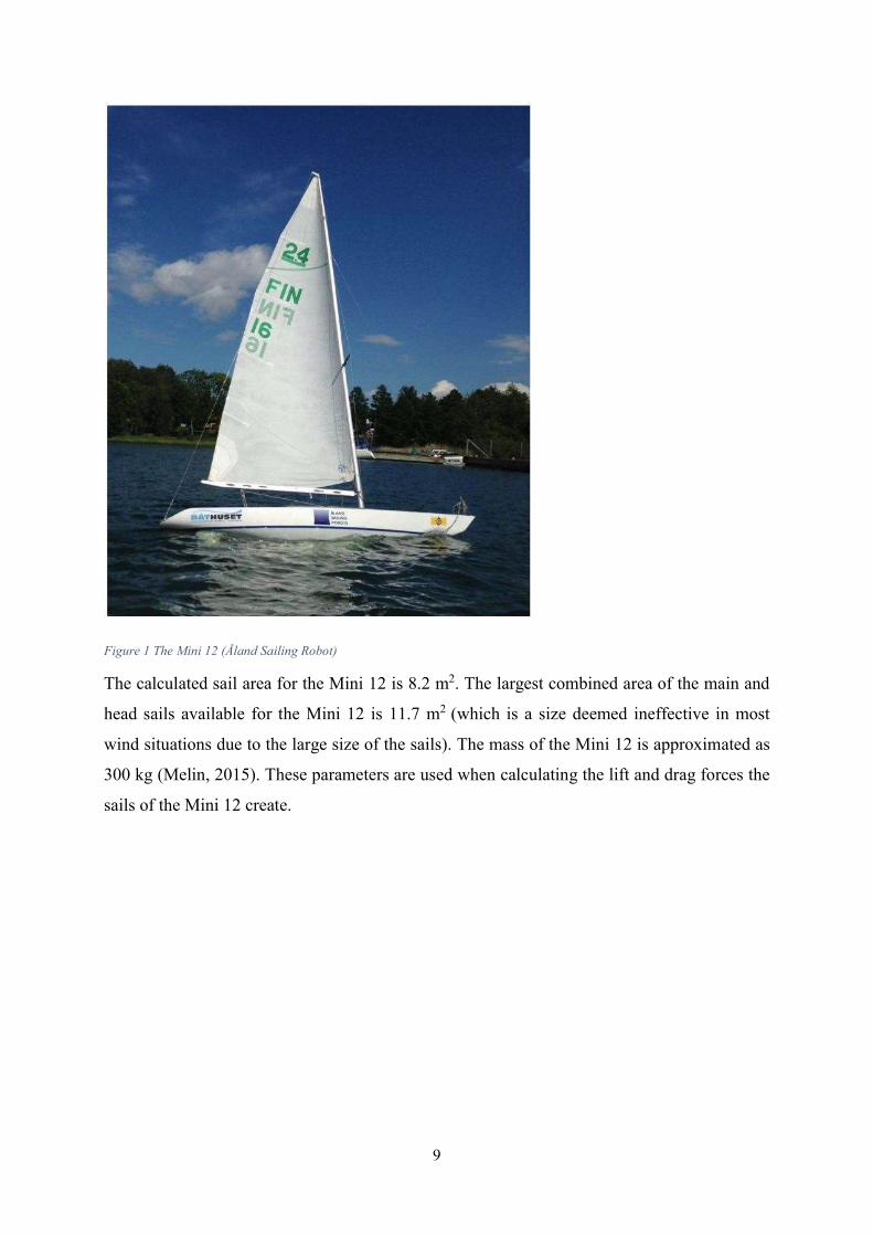
2.2. The Microtransat Challenge Dr. Mark Neal of Aberystwyth University and Dr. Yves Briere of the Institut Supérieure de l'Aéronautique et de l'Espace (ISAE) in Tolouse, started the Microtransat challenge in 2005 as a friendly competition between teams trying to develop autonomous sailing robots. As the name indicates the Microtransat challenge is a transatlantic race which is performed by autonomously sailing vessels. In the competition the contestants only put in the coordinates where the vessel is to sail and the computer will do the rest, a fully autonomous sailing on the part of the computers. The vessel must get from point A to point B independently taking the wind speed/direction, currents and seaway into consideration. (TMC Rules, 2015) The first transatlantic race took place in 2010 with only one team able to launch their boat, namely Aberystwyth University. The boat sailed 87 km autonomously and drifted for 653 km until the last message from an independent tracing unit was received after 18 days, the boat was not found again. (TMC History, 2015). Teams gather once a year to compete in order to win the world championship in robotic sailing. The gathering takes place in some part of the world (every year a new location) in a conference called the World Robotic Sailing Championship and International Robotic Sailing Conference (WRSC/IRSC). Much like the Microtransat Challenge the WRSC is a competition open to fully autonomous and unmanned sailing boats but unlike the Microtransat Challenge the WRSC focuses on the complex task of sailing, including best routing decision, perfect handling of ever changing wind conditions and perfect timing during tack and jibe which are some of the skills an autonomous sailing vessel has to master (WRSC, 2015). 2.2.1. Mini 12 The Mini 12 is one of the smallest one-manned sailboat models with a fixed keel in the world. With a waterline under 4 m it fills the criteria of the Microtransat Challenge, 2005 (TMC) and the World Robotic Sailing Championship for the 4 m LOA class (WRSC). Therefore we will be focusing this research around the Mini 12 (see Figure 1). Mini 12 is the definition for a competitive class of sail boats. International 2.4 Metre Class is the official name of the class and it is used around the world. The name Mini 12 for the boats comes from the first boats constructed for the class in a scale of 1:5 of the original 12-Metre yachts (12/5=2.4). (Svenska 2.4mR Förbundet, 2014)
9
Figure 1 The Mini 12 (Åland Sailing Robot) The calculated sail area for the Mini 12 is 8.2 m2. The largest combined area of the main and head sails available for the Mini 12 is 11.7 m2 (which is a size deemed ineffective in most wind situations due to the large size of the sails). The mass of the Mini 12 is approximated as 300 kg (Melin, 2015). These parameters are used when calculating the lift and drag forces the sails of the Mini 12 create.
10
3. METHODS OF WIND ASSISTED PROPULSION In the late 1970s and the early 1980s the price of crude oil rose sharply. As a result of this a report was commissioned by MARAD (U.S Maritime Administration) entitled ‘Wind propulsion for the ships of the American merchant marine’ by Lloyd Bergeson (Bergeson, 1981), with the overall objective to provide a systematic analysis of the various options with respect to wind power as ship propulsion. These propulsion applications can be split into two groups, namely:
1. Sole Power Unit (SPU) 2. Auxiliary Power Unit (APU)
The SPU application is used mostly on yachts or catamarans as the sole power unit operated by the crew whilst the APU is mostly used on larger powered craft as an auxiliary power unit i.e. cargo ships, passenger liners or fishing boats. APUs are normally controlled by a microprocessor directly from the engine control unit (Atkins, 1996). There are three main types of wind power units namely, soft sails, mechanical devices and wing sails. These three power units all have their advantages and disadvantages which will be discussed briefly, however the sail area must be determined between these three power units for the results to be directly comparable. (Bergeson, 1981) 3.1. Conventional (soft) Sails Sailing with conventional cloth sails has been practiced all around the world for thousands of years so it is safe to say that the sail works, because only a functioning concept could be used for thousands of years by humans who are known to always try to improve things. When air interacts with sails of a sailing vessel it creates various forces, one of them being reaction forces. If the sails are properly orientated against the wind, the net force on the sail will move the vessel forward. However vessels propelled by sails cannot sail directly against the wind. Sailing into the wind requires a sailing method called tacking/beating (turning the boat through the eye of the wind back and forth in order to progress directly upwind) creating a zig-zag course which allows the vessel to advance indirectly upwind (Wikipedia, 2016). Perfectly trimmed sloop rigs (Jib and main sail) have a maximum lift coefficient (CLmax) ≈0.8 (Elkaim, 2008)
11
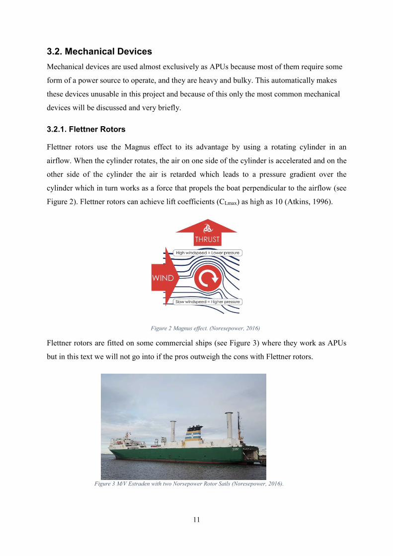
3.2. Mechanical Devices Mechanical devices are used almost exclusively as APUs because most of them require some form of a power source to operate, and they are heavy and bulky. This automatically makes these devices unusable in this project and because of this only the most common mechanical devices will be discussed and very briefly. 3.2.1. Flettner Rotors Flettner rotors use the Magnus effect to its advantage by using a rotating cylinder in an airflow. When the cylinder rotates, the air on one side of the cylinder is accelerated and on the other side of the cylinder the air is retarded which leads to a pressure gradient over the cylinder which in turn works as a force that propels the boat perpendicular to the airflow (see Figure 2). Flettner rotors can achieve lift coefficients (CLmax) as high as 10 (Atkins, 1996).
Flettner rotors are fitted on some commercial ships (see Figure 3) where they work as APUs but in this text we will not go into if the pros outweigh the cons with Flettner rotors.
Figure 3 M/V Estraden with two Norsepower Rotor Sails (Noresepower, 2016).
Figure 2 Magnus effect. (Noresepower, 2016)

12
3.2.2. Vertical/Horizontal Axis Turbine Vertical and horizontal axis turbines are similar to their power generating counterparts which create electricity for domestic use, but unlike those which create electrical power these power the vessel (see Figure 4). The size these devices require is large, especially with the horizontal axis turbine, which is a major disadvantage on conventional ships. However the ability to create power in all wind directions is one of the advantages these devices have (Bergeson, 1981).
Figure 4 Vertical/Horizontal axis turbines as fitted on ships. Figures retrieved form (Bergeson, 1981)
Some researchers have suggested combining the vertical axis turbine with a Flettner rotor thus eliminating the need for a power source to rotate the Flettner rotor. Arrangements like these have not yet appeared on conventional ships as far as the author of this text is aware, but with the trend of “going green” the future is looking bright for these and other various mechanical devices in shipping, for autonomous sailing robots however these are mostly unsuitable.
13
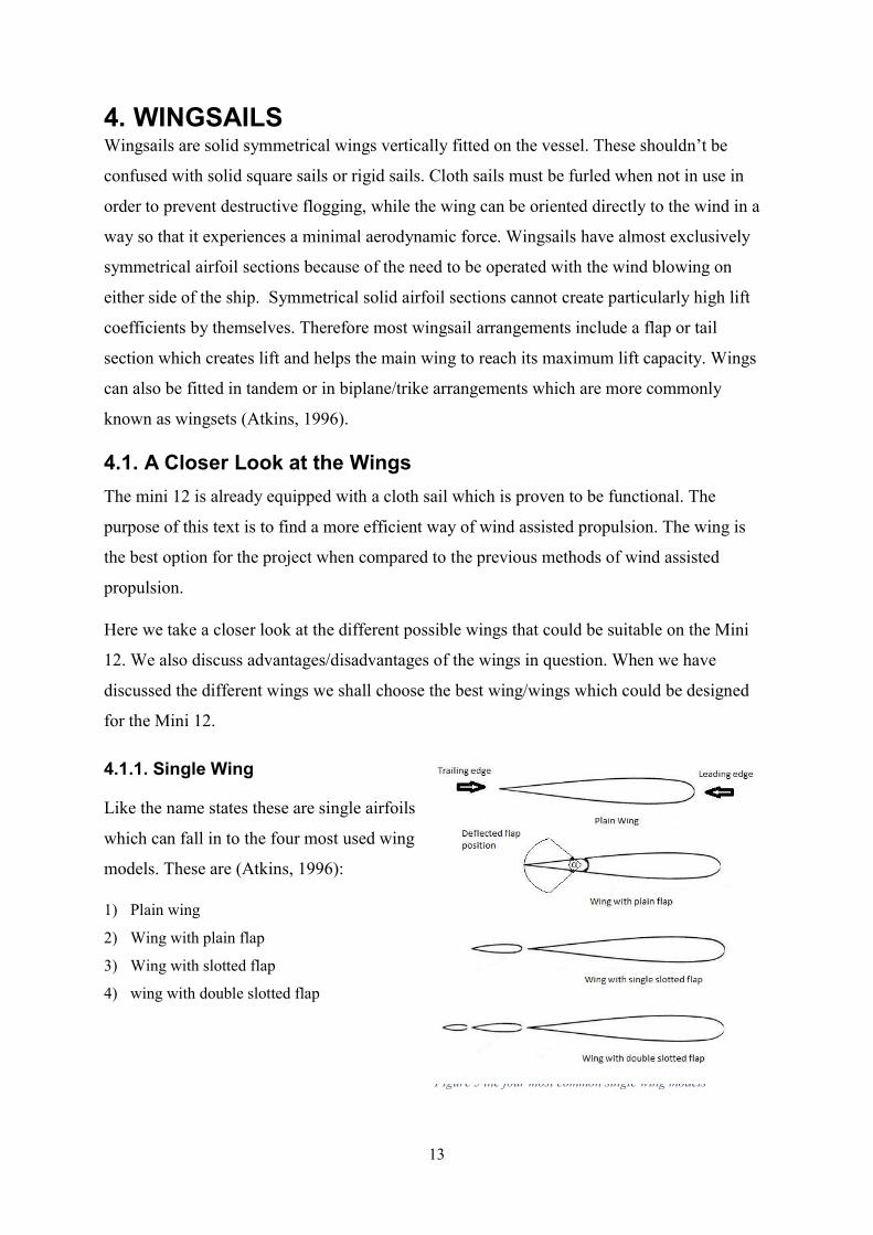
Figure 5 the four most common single wing models
4. WINGSAILS Wingsails are solid symmetrical wings vertically fitted on the vessel. These shouldn’t be confused with solid square sails or rigid sails. Cloth sails must be furled when not in use in order to prevent destructive flogging, while the wing can be oriented directly to the wind in a way so that it experiences a minimal aerodynamic force. Wingsails have almost exclusively symmetrical airfoil sections because of the need to be operated with the wind blowing on either side of the ship. Symmetrical solid airfoil sections cannot create particularly high lift coefficients by themselves. Therefore most wingsail arrangements include a flap or tail section which creates lift and helps the main wing to reach its maximum lift capacity. Wings can also be fitted in tandem or in biplane/trike arrangements which are more commonly known as wingsets (Atkins, 1996). 4.1. A Closer Look at the Wings The mini 12 is already equipped with a cloth sail which is proven to be functional. The purpose of this text is to find a more efficient way of wind assisted propulsion. The wing is the best option for the project when compared to the previous methods of wind assisted propulsion. Here we take a closer look at the different possible wings that could be suitable on the Mini 12. We also discuss advantages/disadvantages of the wings in question. When we have discussed the different wings we shall choose the best wing/wings which could be designed for the Mini 12. 4.1.1. Single Wing Like the name states these are single airfoils which can fall in to the four most used wing models. These are (Atkins, 1996): 1) Plain wing 2) Wing with plain flap 3) Wing with slotted flap 4) wing with double slotted flap
14
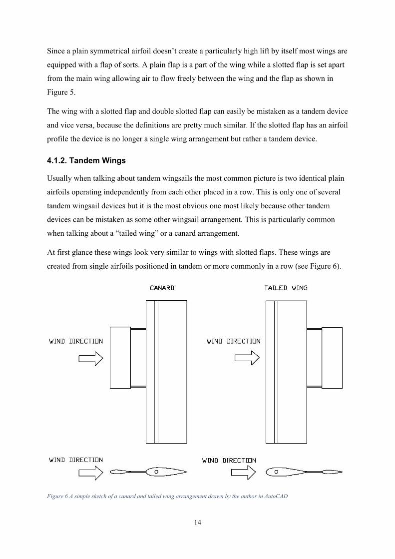
Since a plain symmetrical airfoil doesn’t create a particularly high lift by itself most wings are equipped with a flap of sorts. A plain flap is a part of the wing while a slotted flap is set apart from the main wing allowing air to flow freely between the wing and the flap as shown in Figure 5. The wing with a slotted flap and double slotted flap can easily be mistaken as a tandem device and vice versa, because the definitions are pretty much similar. If the slotted flap has an airfoil profile the device is no longer a single wing arrangement but rather a tandem device. 4.1.2. Tandem Wings Usually when talking about tandem wingsails the most common picture is two identical plain airfoils operating independently from each other placed in a row. This is only one of several tandem wingsail devices but it is the most obvious one most likely because other tandem devices can be mistaken as some other wingsail arrangement. This is particularly common when talking about a “tailed wing” or a canard arrangement. At first glance these wings look very similar to wings with slotted flaps. These wings are created from single airfoils positioned in tandem or more commonly in a row (see Figure 6).
Figure 6 A simple sketch of a canard and tailed wing arrangement drawn by the author in AutoCAD
15
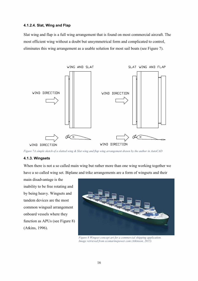
4.1.2.1. Tailed Wing When talking about autonomous sailing vessels the most common tandem wing arrangement is a controllable tail behind fully rotational wing. The fully rotational wing has an advantage in the ability of being made self-trimming. This leads to the effect that the control system design can be greatly simplified. The self-trimming ability will be discussed more in detail in chapter 6. The tailed wing arrangement has the immediate disadvantage of being tail heavy which must be compensated for with ballast forward of the main wing to place the center of mass of the wing arrangement in the desired position. Ballast in the wing in turn causes the boats center of gravity to rise which makes the boat more prone to capsizing. The wing also has a somewhat large rotational radius which can create issues, i.e. being free rotating the wing and tail arrangement can cause damage to itself or other boats in its close vicinity, however this is not an issue out at sea where the boats usually spend most of their time. 4.1.2.2. Canard A canard arrangement is very similar to a tailed wing with the exception of the “tail” being in front of the main wing rather than behind the main wing. This wing arrangement has the advantage of a possibly more balanced weight placement compared to a tailed wing, meaning that a canard wing doesn’t necessary need as much ballast in order for the wing to reach its mass center at the desired position. Also the turning radius is smaller for a Canard arrangement. However according to some researchers the canard arrangement is a lot more unstable when freely rotational than the tailed wing in varying wind conditions. 4.1.2.3. Wing and Slat A slat in front of the wing is something that is very common in aircraft and other applications that use unsymmetrical airfoils (see Figure 7). Unsymmetrical airfoil design makes a slatted wing unusable as a wingsail application. A slatted wing arrangement with a symmetrical airfoil would have to be more like a Canard design in order to function in all wind directions.
16
4.1.2.4. Slat, Wing and Flap Slat wing and flap is a full wing arrangement that is found on most commercial aircraft. The most efficient wing without a doubt but unsymmetrical form and complicated to control, eliminates this wing arrangement as a usable solution for most sail boats (see Figure 7).
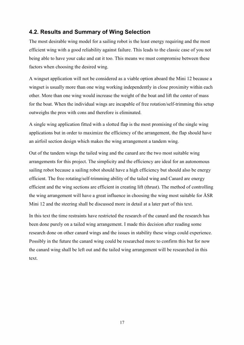
Figure 7A simple sketch of a slatted wing & Slat wing and flap wing arrangement drawn by the author in AutoCAD 4.1.3. Wingsets When there is not a so called main wing but rather more than one wing working together we have a so called wing set. Biplane and trike arrangements are a form of wingsets and their main disadvantage is the inability to be free rotating and by being heavy. Wingsets and tandem devices are the most common wingsail arrangement onboard vessels where they function as APUs (see Figure 8) (Atkins, 1996).
Figure 8 Wingset concept art for a commercial shipping application. Image retrieved from ecomarinepower.com (Atkinson, 2015)
17
4.2. Results and Summary of Wing Selection The most desirable wing model for a sailing robot is the least energy requiring and the most efficient wing with a good reliability against failure. This leads to the classic case of you not being able to have your cake and eat it too. This means we must compromise between these factors when choosing the desired wing. A wingset application will not be considered as a viable option aboard the Mini 12 because a wingset is usually more than one wing working independently in close proximity within each other. More than one wing would increase the weight of the boat and lift the center of mass for the boat. When the individual wings are incapable of free rotation/self-trimming this setup outweighs the pros with cons and therefore is eliminated. A single wing application fitted with a slotted flap is the most promising of the single wing applications but in order to maximize the efficiency of the arrangement, the flap should have an airfoil section design which makes the wing arrangement a tandem wing. Out of the tandem wings the tailed wing and the canard are the two most suitable wing arrangements for this project. The simplicity and the efficiency are ideal for an autonomous sailing robot because a sailing robot should have a high efficiency but should also be energy efficient. The free rotating/self-trimming ability of the tailed wing and Canard are energy efficient and the wing sections are efficient in creating lift (thrust). The method of controlling the wing arrangement will have a great influence in choosing the wing most suitable for ÅSR Mini 12 and the steering shall be discussed more in detail at a later part of this text. In this text the time restraints have restricted the research of the canard and the research has been done purely on a tailed wing arrangement. I made this decision after reading some research done on other canard wings and the issues in stability these wings could experience. Possibly in the future the canard wing could be researched more to confirm this but for now the canard wing shall be left out and the tailed wing arrangement will be researched in this text.
18
4.3. Performance Comparison between Cloth/Wing Sails and Mechanical Devices When comparing these three methods of wind assisted propulsion (soft sails, mechanical devices and wingsails) we can not only look at the efficiency. Various other factors also play part in the decision of which method is most suitable and should be used. For this project the main factors not including efficiency are:
1. Economic viability 2. Simplicity 3. Reliability 4. Autonomous operationality 5. Design and installation
The mechanical devices even though efficient are only auxiliary power units and don’t fill the desired criteria for the factors outside efficiency. Therefore the three mechanical devices discussed earlier are unusable in this project. The soft sail application is fitted on the ÅSR Mini 12 and has been proven to work. That leaves only the wing. Not only is the wing more efficient than the soft sail application, it also fills all the five criteria as well as the superior efficiency. These five criteria for the wing will be described later in chapter 6.
19
4.4. Theory and Reality and the Issues that Follow This project is a theoretical investigation regarding whether a wingsail application would be suitable to provide propulsion to the autonomous sailing robot of ÅSR. However even at an early stage in the text it is abundantly clear that a wingsail is a superior method of wind assisted propulsion compared to conventional soft sails, yet only researching theoretically is not enough to persuade the people at ÅSR to start building a wingsail application. There are numerous challenges when fitting a wingsail on an autonomous sailing robot and some of these should be researched thoroughly before the decision of building the wing arrangement is made. The main challenges are:
Steering the wing arrangement Free rotating capability Wiring to the wing or to the top of the mast How to make the aerodynamic and mass center align
Even though this text is purely theoretical, the practical aspects of this project should not be dismissed and possible solutions should be offered to these challenges. The solutions to these challenges are some of the last things written in this text because of the fact that the challenges and solutions are something that depend on the design of the wing arrangement and vice versa. These challenges will be discussed later in this text and hopefully suitable solutions will be found by then.2
2 This is the kind of things the author of this text is most comfortable in doing, because of previous jobs and education which have been mostly planning, construction and improving various existing applications and machinery. Not to dismiss the vast major part of this project which is the theoretical aspect of this text and as a Finnish saying goes, well planned is half finished.
20
5. THEORY BEHIND THE WING 5.1. Design Criteria of Wingsails Wingsails and wings mounted on aircraft differ quite much because a wingsail must be able to sail with the wind coming from both port and starboard, whilst most aircraft only fly upright. This leads to a symmetrical airfoil design similar to the wings mounted on most stunt planes which are required to fly upright and upside down, which is comparable to wind directions from both port and starboard. Apart from the symmetrical airfoil design, wingsails and airplane wings are rather similar design wise. Both wings should be light and sturdy at the same time. This aspect is more important for aircraft and we could write a whole paper on the mechanical requirements on aircraft wings but the main idea is the same for wings and wingsails, light and sturdy. Outside of the somewhat constructional design criteria for wings and wingsails, there are some major differences in the way these wings behave. These wings work along the same principle that the both wings experience a combination of lift and drag characteristics which in turn create thrust to propel the sail boat and keeps an airplane airborne. Wingsails and airplanes operate at very different conditions. Airplanes operate at high altitude in mostly lower temperatures and at incredible speeds, compared to wingsails which operate at sea level, mostly warmer weather and at low speeds. The characteristics of these wings differ quite a lot and the main reasons for that shall be discussed in this text below. However the behaviour of airfoils at low airspeeds is a very complicated issue which cannot fully be explained in this text partly because of the inexperience in the matter of the author but also because of the time restraints imposed by the due date of this text. 5.2. Aerodynamic Forces The aerodynamic forces acting on a surface that is exposed to wind is most commonly broken down into two components, namely aerodynamic lift and aerodynamic drag. Aerodynamic lift is the force component which acts perpendicular to the wind. It is the result of deflection of the wind as it flows past a surface and acts opposite to the direction the flow is deflected. It is lift force that allows a wing to “lift” an airplane as it flies forward. Lift force allows a sail rig to provide forward thrust when apparent wind is on the beam or forward of the beam. (Bergeson, 1981)
21
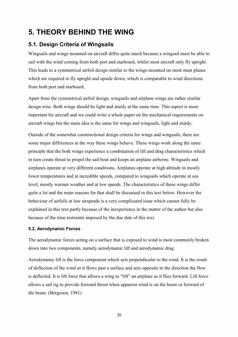
Aerodynamic drag is the force component in the direction of the apparent wind. It is the result of obstruction or retarding of wind as it flows past an object or surface. For sail rigs, aerodynamic drag provides thrust when the apparent wind is aft of the beam, and reduces thrust when the wind is forward of the beam. (Bergeson, 1981) When combining these two forces the resultant becomes the total aerodynamic force acting over a wing (See Figures 9 and 10).
Figure 9 Lift and Drag forces acting over an airfoil to create the total aerodynamic force (Wikipedia, 2016)
22
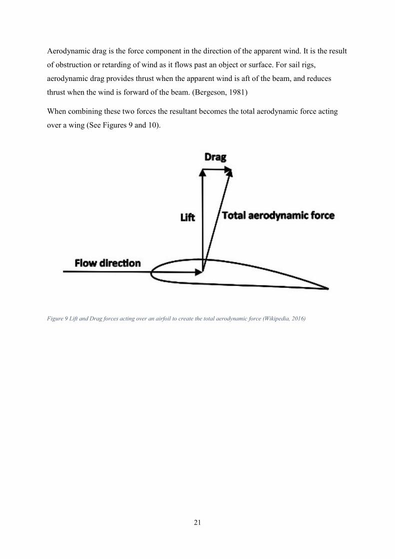
5.3. Apparent Wind Apparent wind velocity (VA) is the result of vectorially adding the wind induced by the boat’s speed (VS) and the true wind velocity (VT). This makes the apparent wind equal the resultant of the wind induced by the vessels velocity and the true wind velocity (see Figure 10). This means that the airflow used in the upcoming calculations and simulations will be set as the apparent wind velocity.
Figure 10 is a simple sketch that shows a simple scenario where the induced wind (vessel velocity) is the same as the true wind which leads the apparent wind to be 1.4 times greater than the vessel and wind velocity (Pythagoras’ theorem). In reality these velocity vectors usually occur in various different sizes at different incidences. 5.4. NACA Airfoils NACA (National Advisory Committee for Aeronautics) was founded in 1915 with the intent of being an advisory committee for coordinated research underway elsewhere. However, it quickly became a leading research organization in aeronautics and the new field of astronautics; pushing back the boundaries of flight through the first supersonic flights and also some of the research that would lead to the human space program under its successor, NASA, to which the NACA passed the torch in 1958. (Suckow, 2009)
Figure 10 A simple sketch of the velocity vectors
23
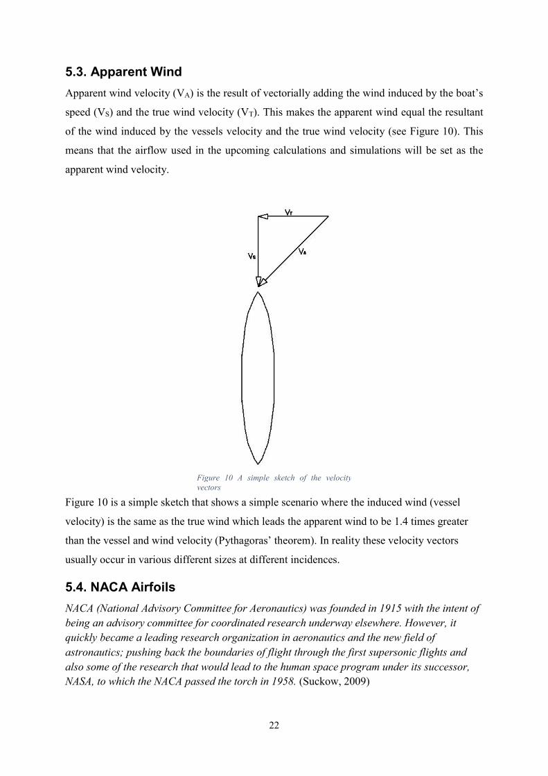
An airfoil (in American English) or aerofoil (in British English) is the shape of a wing, blade (of a propeller, rotor, or turbine), or sail (as seen in cross-section). See Figure 11.
5.4.1. Four-Digit Series In a NACA four-digit series, the first digit specifies the maximum camber in percentage of the chord (The length of the airfoil). The second digit indicates the position of the maximum camber in tenths of the chord and the last two digits indicate the maximum thickness of the airfoil in percentage of the chord. As an example of a NACA four-digit series, let us look for example at the NACA 2310. It has a maximum thickness of 10%, a camber of 2% located 30% back from the airfoil leading edge (see Figure 11). In Figure 11 NACA 2310 is drawn in a computer program named JavaFoil. This program is used in this project as a means of two-dimensional airfoils analysis and will be discussed in greater detail later in this text. There are numerous computer programs for drawing NACA airfoils and retrieving coordinates for airfoils. These programs most likely use the methodology that has been used since the 1930s when drawing airfoils. When drawing four-digit airfoils (Scott, 2001):
Figure 11 A NACA 2310 airfoil drawn in JavaFoil
24
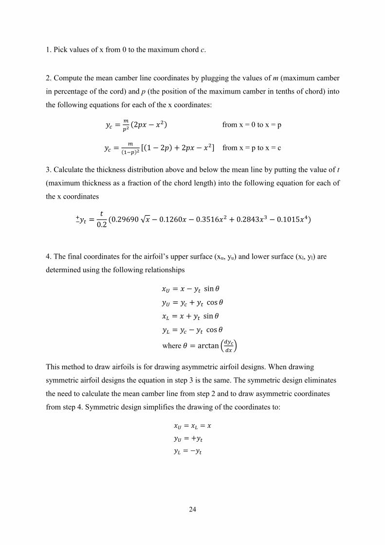
1. Pick values of x from 0 to the maximum chord c. 2. Compute the mean camber line coordinates by plugging the values of m (maximum camber in percentage of the cord) and p (the position of the maximum camber in tenths of chord) into the following equations for each of the x coordinates:
= (2 − ) from x = 0 to x = p
= ( ) (1 − 2 ) + 2 − from x = p to x = c 3. Calculate the thickness distribution above and below the mean line by putting the value of t (maximum thickness as a fraction of the chord length) into the following equation for each of the x coordinates
= 0.2 (0.29690 √ − 0.1260 − 0.3516 + 0.2843 − 0.1015 )
4. The final coordinates for the airfoil’s upper surface (xu, yu) and lower surface (xl, yl) are determined using the following relationships
= − sin = + cos
= + sin = − cos where = arctan This method to draw airfoils is for drawing asymmetric airfoil designs. When drawing symmetric airfoil designs the equation in step 3 is the same. The symmetric design eliminates the need to calculate the mean camber line from step 2 and to draw asymmetric coordinates from step 4. Symmetric design simplifies the drawing of the coordinates to:
= = = + = −
25
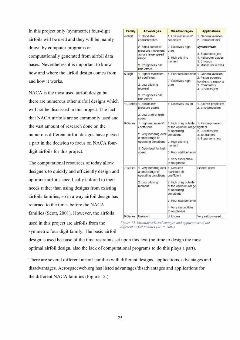
In this project only (symmetric) four-digit airfoils will be used and they will be mainly drawn by computer programs or computationally generated from airfoil data bases. Nevertheless it is important to know how and where the airfoil design comes from and how it works. NACA is the most used airfoil design but there are numerous other airfoil designs which will not be discussed in this project. The fact that NACA airfoils are so commonly used and the vast amount of research done on the numerous different airfoil designs have played a part in the decision to focus on NACA four-digit airfoils for this project. The computational resources of today allow designers to quickly and efficiently design and optimize airfoils specifically tailored to their needs rather than using designs from existing airfoils families, so in a way airfoil design has returned to the times before the NACA families (Scott, 2001). However, the airfoils used in this project are airfoils from the symmetric four digit family. The basic airfoil design is used because of the time restraints set upon this text (no time to design the most optimal airfoil design, also the lack of computational programs to do this plays a part). There are several different airfoil families with different designs, applications, advantages and disadvantages. Aerospaceweb.org has listed advantages/disadvantages and applications for the different NACA families (Figure 12.)
Figure 12 Advantages/Disadvantages and applications of the different airfoil families (Scott, 2001)
26
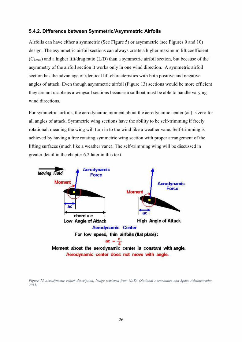
5.4.2. Difference between Symmetric/Asymmetric Airfoils Airfoils can have either a symmetric (See Figure 5) or asymmetric (see Figures 9 and 10) design. The asymmetric airfoil sections can always create a higher maximum lift coefficient (CLmax) and a higher lift/drag ratio (L/D) than a symmetric airfoil section, but because of the asymmetry of the airfoil section it works only in one wind direction. A symmetric airfoil section has the advantage of identical lift characteristics with both positive and negative angles of attack. Even though asymmetric airfoil (Figure 13) sections would be more efficient they are not usable as a wingsail sections because a sailboat must be able to handle varying wind directions. For symmetric airfoils, the aerodynamic moment about the aerodynamic center (ac) is zero for all angles of attack. Symmetric wing sections have the ability to be self-trimming if freely rotational, meaning the wing will turn in to the wind like a weather vane. Self-trimming is achieved by having a free rotating symmetric wing section with proper arrangement of the lifting surfaces (much like a weather vane). The self-trimming wing will be discussed in greater detail in the chapter 6.2 later in this text.
Figure 13 Aerodynamic center description. Image retrieved from NASA (National Aeronautics and Space Administration, 2015)
27
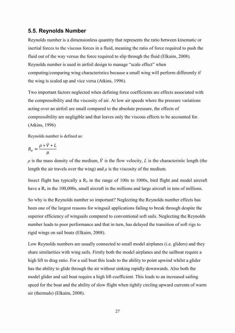
5.5. Reynolds Number Reynolds number is a dimensionless quantity that represents the ratio between kinematic or inertial forces to the viscous forces in a fluid, meaning the ratio of force required to push the fluid out of the way versus the force required to slip through the fluid (Elkaim, 2008). Reynolds number is used in airfoil design to manage “scale effect” when computing/comparing wing characteristics because a small wing will perform differently if the wing is scaled up and vice versa (Atkins, 1996). Two important factors neglected when defining force coefficients are effects associated with the compressibility and the viscosity of air. At low air speeds where the pressure variations acting over an airfoil are small compared to the absolute pressure, the effects of compressibility are negligible and that leaves only the viscous effects to be accounted for. (Atkins, 1996) Reynolds number is defined as:
= ∗ ∗ ρ is the mass density of the medium, is the flow velocity, L is the characteristic length (the length the air travels over the wing) and μ is the viscosity of the medium. Insect flight has typically a Re in the range of 100s to 1000s, bird flight and model aircraft have a Re in the 100,000s, small aircraft in the millions and large aircraft in tens of millions. So why is the Reynolds number so important? Neglecting the Reynolds number effects has been one of the largest reasons for wingsail applications failing to break through despite the superior efficiency of wingsails compared to conventional soft sails. Neglecting the Reynolds number leads to poor performance and that in turn, has delayed the transition of soft rigs to rigid wings on sail boats (Elkaim, 2008). Low Reynolds numbers are usually connected to small model airplanes (i.e. gliders) and they share similarities with wing sails. Firstly both the model airplanes and the sailboat require a high lift to drag ratio. For a sail boat this leads to the ability to point upwind whilst a glider has the ability to glide through the air without sinking rapidly downwards. Also both the model glider and sail boat require a high lift coefficient. This leads to an increased sailing speed for the boat and the ability of slow flight when tightly circling upward currents of warm air (thermals) (Elkaim, 2008).
28
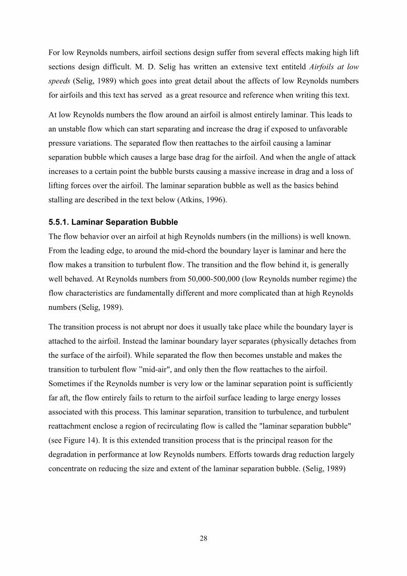
For low Reynolds numbers, airfoil sections design suffer from several effects making high lift sections design difficult. M. D. Selig has written an extensive text entiteld Airfoils at low speeds (Selig, 1989) which goes into great detail about the affects of low Reynolds numbers for airfoils and this text has served as a great resource and reference when writing this text. At low Reynolds numbers the flow around an airfoil is almost entirely laminar. This leads to an unstable flow which can start separating and increase the drag if exposed to unfavorable pressure variations. The separated flow then reattaches to the airfoil causing a laminar separation bubble which causes a large base drag for the airfoil. And when the angle of attack increases to a certain point the bubble bursts causing a massive increase in drag and a loss of lifting forces over the airfoil. The laminar separation bubble as well as the basics behind stalling are described in the text below (Atkins, 1996). 5.5.1. Laminar Separation Bubble The flow behavior over an airfoil at high Reynolds numbers (in the millions) is well known. From the leading edge, to around the mid-chord the boundary layer is laminar and here the flow makes a transition to turbulent flow. The transition and the flow behind it, is generally well behaved. At Reynolds numbers from 50,000-500,000 (low Reynolds number regime) the flow characteristics are fundamentally different and more complicated than at high Reynolds numbers (Selig, 1989). The transition process is not abrupt nor does it usually take place while the boundary layer is attached to the airfoil. Instead the laminar boundary layer separates (physically detaches from the surface of the airfoil). While separated the flow then becomes unstable and makes the transition to turbulent flow ”mid-air", and only then the flow reattaches to the airfoil. Sometimes if the Reynolds number is very low or the laminar separation point is sufficiently far aft, the flow entirely fails to return to the airfoil surface leading to large energy losses associated with this process. This laminar separation, transition to turbulence, and turbulent reattachment enclose a region of recirculating flow is called the "laminar separation bubble" (see Figure 14). It is this extended transition process that is the principal reason for the degradation in performance at low Reynolds numbers. Efforts towards drag reduction largely concentrate on reducing the size and extent of the laminar separation bubble. (Selig, 1989)
29
Figure 14 The laminar separation bubble structure developing on a covered rib structure at Re 100,000 with the angle of attack (α) 3°. Image retrieved from MH Airfoils (Hepperle, Aerodynamics of Spar&Rib structures, 2000) As described previously, laminar separation takes place at low Reynolds numbers due to the reluctance of the boundary layer to make a natural transition from laminar to turbulent flow on the surface of the airfoil. The laminar separation bubble is a fascinating phenomenon that has been researched numerous times by various researchers around the world. In this text however, the laminar separation bubble will only be discussed briefly and only the most relevant consequence caused by the bubble (stalling) will be discussed. There are two types of laminar separation bubbles controlling the aerodynamic characteristics of airfoils operating at low Reynolds numbers, a short and a long one. The bubble increases drag and reduces lift depending on the bubble’s length because of the varying pressure distribution over the airfoil caused by the bubble. The presence and behavior of the laminar separation bubble is dependent upon the Reynolds number, airfoil shape, free stream turbulence, surface roughness and sound waves (Selig, 1989). 5.5.2. Stalling Most people know the term stalling when talking about aviation, and most people know that it is not something you want your aircraft to experience. Even though stalling can happen to engines leading them to fault (i.e. when a car stalls the engine shuts down), in aviation stalling (unless engine-stalling is specifically mentioned) usually refers to the loss of lifting forces and the increasing of drag forces acting over the wings due to an angle exceeding the critical angle of attack (see Figure 15).
30
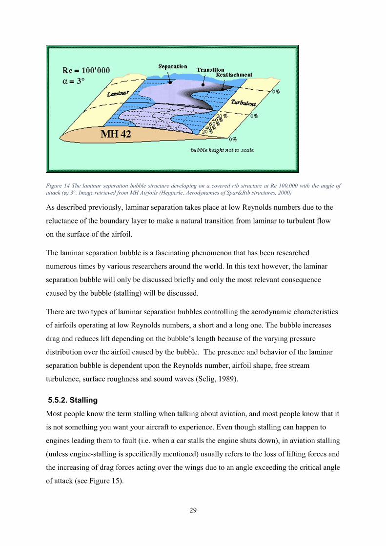
Figure 15 Stall occurring as the airflow separates of an airfoil at a high angle of attack (Wikipedia, 2016)
Flow separations from an airfoils cause stalling, which leads to loss of lift and a rise in drag forces over an airfoil. Stalling occurs when the wing exceeds the critical angle of attack and starts to lose lift and increase its drag. 5.5.2.1. Leading Edge Stall As the name indicates leading edge stall occurs when a laminar separation bubble near the leading edge of an airfoil shortens and suddenly bursts. At low angles of attack a laminar flow region separates and reattaches forming a bubble and as the angle increases, the bubble shortens and moves forward and at some point the boundary layer can’t reattach and the bubble bursts. When the bubble bursts the wing suddenly loses its lifting forces and stalls (see Figure 15). This type of stall is exhibited by airfoils with a thickness between 9% and 15% of the chord length, and at low Reynolds numbers. (Atkins, 1996) 5.5.2.2. Trailing Edge Stall Similar to leading edge stall, the name gives away the position of where the trailing edge stall occurs, but unlike with leading edge stall there is no laminar separation bubble at trailing edge stall. Trailing edge stall occurs when a turbulent boundary layer at the rear of an airfoil separates. The point where separation occurs transitions forward as the angle of attack increases. This type of stall is exhibited by many airfoil sections with a thickness of greater than 15% of the chord length and at high Reynolds numbers. (Atkins, 1996)
31
6. THE WING FOR ÅSR MINI 12 6.1. Aside from Efficiency The Mini 12 is fitted with soft sails which have proven to be operational and efficient. The world robotic sailing championship for 4 m LOA class in 2015 is conclusive proof of that (WRSC, 2015). Even though the soft sails fitted on the Mini 12 are proven functional, the search for the most efficient robotic sailing boat continues. That is the main reason for this project, and a wingsail is the most promising way of increasing the efficiency of Åland Sailing Robots Mini 12. Efficiency is one of the most important factors when discussing robotic sailboats but other factors play a large part too, which was discussed earlier in this text (Chapter 4.3). The factors being:
1. Economic viability 2. Simplicity 3. Reliability 4. Autonomous operation 5. Design and installation
These five factors are of great importance for ensuring the functionality of the autonomous sailing robot by ÅSR or any other team competing with robotic sailing boats. They are essential for a robotic sailing boat to be functional and here we will discuss the five factors and how they affect the wing sail application for ÅSR Mini 12. 6.1.1. Economic Viability. This project is solely a theoretical analysis of the possibility of fitting a wingsail on the Mini 12 and depending on the results of this project a decision will be made regarding the building and fitting of the wing. Just like this project is made by a student at Åland UAS, most likely so will the building and fitting of the wing be too. The costs of construction and fitting of the wing will be relatively low because of the fact that it will be mostly student working on the wing, and doing maintenance on it. This puts close to all the costs solely on materials and components. The cost of these can be as high as the budget allows, this is discussed more in chapter 8. This is of course only if this study proves the wing to be a feasible option for ÅSR Mini 12, and if the decision on building the wing is granted.
32
6.1.2. Simplicity The wing sail is a very “simple” construction in itself. It is a free rotating symmetrical airfoil with a controllable tail section consisting of a smaller symmetrical airfoil. The fact that the wing is free rotating (self-trimming) makes controlling of the wing simple because the only component that requires control is the tail section while the main wing is steered by the wind itself. This is an advantage over the soft sail application that the Mini 12 is fitted with concerning energy consumption for steering the sail. The self-trimming capability is achieved by aligning the center of mass of the wing arrangement at the aerodynamic center of the main wing. This way the wing arrangement will work much like a wind vane meaning it will turn in to the wind. The self-trimming ability will be discussed in detail later in this text. The rigid form of the wings makes it easier and more predictable than soft sails in different wind scenarios. This is because a rigid wing doesn’t suffer from aeroelastic collapse (also known as luffing) when pointed high into the wind, unlike soft sails. Aeroelastic collapse causes a great deal of drag and limits the angle the boat can sail into the wind. The rigid wing does not suffer from any aeroelastic problems and can point straight into the wind with very little drag. 6.1.3. Reliability Not much can be said about the reliability of the wing, namely because of the fact that the wing is not constructed and the reliability of the coming components are not established. Is the wing more reliable than the soft sails fitted on the Mini 12? It is hard to say but the fact that only the tail section is to be controllable makes steering the wing application “relatively simple” meaning that in order to steer the wingsail application not too many components are needed. This leads to a high redundancy for controlling the wing application. Redundancy can be like a double-edged sword. In this case less components makes the risk for failure smaller but it also makes recovery from one component failing much harder. All in all it is unlikely that the reliability of the wing will be lessened compared to the soft sails.
33
6.1.4. Autonomous Operationality The free rotating/self-trimming ability of the wing arrangement makes it ideal for autonomous sailing, because the wing doesn’t need very powerful and fast acting servos to constantly retrim the sails but uses the wind itself to steer the main wing. The maneuvers used with the wing sail arrangement are gentle and controlled because of the free rotating capability which makes only the tail section require some sort of control and because of the fact that a wing can point straight into the wind with close to zero negative effects. Combining the self-trimming ability and the efficiency to create thrust, the self-trimming wing arrangement is very suitable for autonomous operationality. 6.1.5. Design and Installation An important aspect in order to secure the functionality of wingsail applications is design and installation because this is directly related to the functionality of the wings. The design and installation aspects will be researched later in this text but the installation part can be briefly mentioned at this stage of the text, and installation and design go to some extent hand in hand. Not only should the installation be manageable, it should also be possible without major difficulty. This can be an issue because of the size the wing must most likely be in order to propel the Mini 12. Of course when assembling or disassembling the wingsail the rigid form of the wing will cause issues. A wing is a lot more difficult to get off/on the mast than for example when raising/lowering sails. Installation may prove to be the first major disadvantage of wingsails over soft sails, depending on the wingsail and how it will be mounted on the mast. The rigid form of the wing makes assembly/disassembly by hand difficult and in worst case a crane of sorts must be used in order to mount the wing to the mast. On the other hand, when the mast is lowered and the wing dismounted also the boat itself is usually out of the water. When this occurs usually a crane is present which lifts boats in/out of the water. Major problems can occur if the boat is moored for a longer time and the wing is not disassembled. Having the wing freely rotating and positioned in a neutral setting allows the wing arrangement to freely rotate into the wind without creating thrust, however this requires the boat to be positioned in a way that the turning radius is at safe distance to anything the wing could hit while turning freely. The weight of the wing arrangement should be as low as possible, not only to keep the mass center of the boat low but also to ease installation. These design and installation aspects of the wing arrangement will be discussed more in detail later in this text.
34
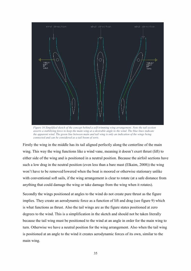
6.2. A Self-Trimming Wing Arrangement As stated earlier several times a self-trimming wing arrangement works basically as a wind vane, where the wind itself steers the wing to point directly into the wind and thus eliminating the need to constantly steer the wing in minor variations in wind direction. When fitted with a tail to steer the main wing the “wing arrangement” can maintain maximum efficiency in any wind direction without disturbance. Also the wing arrangement doesn’t cause the sailboat to list as much as a cloth sail in different wind directions because the wing turns straight in to the wind. This free rotating capability is achieved by aligning the aerodynamic center of the main wing and the mass center of the wing arrangement at the mast where bearings are fitted which allow the wing to rotate with close to zero resistance. The aerodynamic center and center of pressure on a symmetrical airfoil are positioned precisely one quarter of the chord behind the leading edge (see Figure 13), (National Aeronautics and Space Administration, 2015) and this is where the mast should be positioned. The mass center must be manually aligned using ballast in front of the wing in order to get it to align with the mast. This is discussed in greater detail in chapter 8. Figure 16 is a simple sketch of the self-trimming wing arrangement drawn in AutoCAD and the main purpose of the sketch is to give the reader a picture of the concept behind the self-trimming wing arrangement. As stated earlier Figure 16 is a gross simplification of the self-trimming wing arrangement drawn without any intention of being a real drawing, but rather drawn with the intention of easing the description of a self-trimming wing arrangement. The main function in the picture is correct, however a more correct description is required in order to grasp the concept in a satisfactory manner.
35
Figure 16 Simplified sketch of the concept behind a self-trimming wing arrangement. Note the tail section asserts a stabilizing force to keep the main wing at a desirable angle to the wind. The blue lines indicate the apparent wind. The green line between main and tail wing is only an indication of the wings being connected and can be considered as a tail boom of sorts.
Firstly the wing in the middle has its tail aligned perfectly along the centerline of the main wing. This way the wing functions like a wind vane, meaning it doesn’t exert thrust (lift) to either side of the wing and is positioned in a neutral position. Because the airfoil sections have such a low drag in the neutral position (even less than a bare mast (Elkaim, 2008)) the wing won’t have to be removed/lowered when the boat is moored or otherwise stationary unlike with conventional soft sails, if the wing arrangement is clear to rotate (at a safe distance from anything that could damage the wing or take damage from the wing when it rotates). Secondly the wings positioned at angles to the wind do not create pure thrust as the figure implies. They create an aerodynamic force as a function of lift and drag (see figure 9) which is what functions as thrust. Also the tail wings are as the figure states positioned at zero degrees to the wind. This is a simplification in the sketch and should not be taken literally because the tail wing must be positioned to the wind at an angle in order for the main wing to turn. Otherwise we have a neutral position for the wing arrangement. Also when the tail wing is positioned at an angle to the wind it creates aerodynamic forces of its own, similar to the main wing.
36
6.3. Calculations Behind the Wing Design Simplified lifting theory is the same for sailboats as well as for planes, meaning the same equations are usable when calculating the lift generated by a soft sail or a wingsail. When calculating the lift coefficient for a wing or a sail the equation is (Wikipedia, 2016): = ∗ ∗ where CL is the Lift Coefficient, L is the Lift force, ρ is the density of the fluid, V is the true airspeed and A is the sail area. When calculating the drag coefficient for a wing or a sail the equation is (Wikipedia, 2016): = ∗ ∗
where CD is the Drag Coefficient and D is the drag force. Knowing the lift and drag coefficients for different wing sections allows us to calculate the lift and drag forces the wing sections create.
= 12 ∗ ∗ ∗ ∗
= 12 ∗ ∗ ∗ ∗
By using these equations we can assume the lift the current sail generates by inserting a lift coefficient into the equation (a generous assumption would be a CL of 0.8) and design a wing with similar or better lift capabilities. However calculating the drag the current sail generates is not applicable with the drag equation because of the lack of information about the drag coefficients the sail generates. The fact that the drag coefficients are unknown for the cloth sail does not hinder the wing designing because many airfoils have a smaller drag coefficient than a bare mast (Elkaim, 2008), meaning it is safe to assume that the drag will decrease immensely if the cloth sail is exchanged to a rigid wing sail. So in conclusion, when calculating the properties of the soft sails fitted onboard the Mini12 a lot of assumptions must be made because of the lack of information about how the sail functions in various wind characteristics and that in turn leads to unprecise results. The sail area A is calculated with the formula:
≈ ∗ ∗
37
where P is the height of the sail, E is the width of the sail and k is 0.62 when calculating the area of the main sail and 0.5 when calculating the area of the jibs. The wing area A is calculated with the formula:
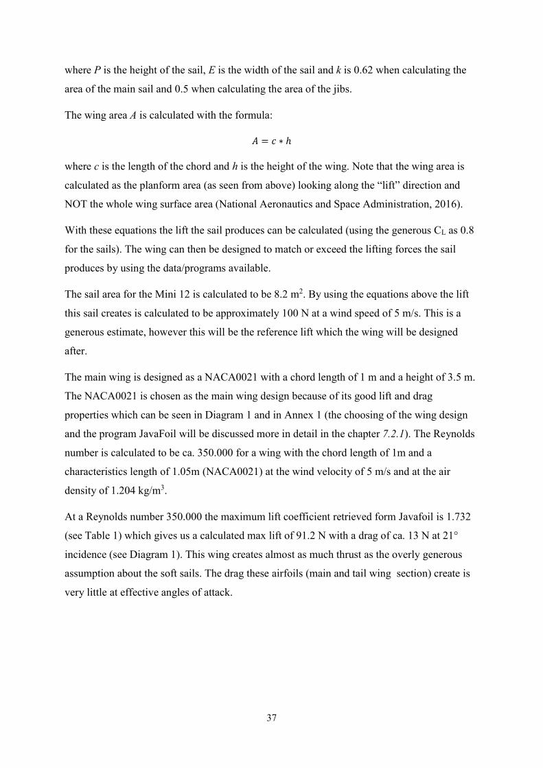
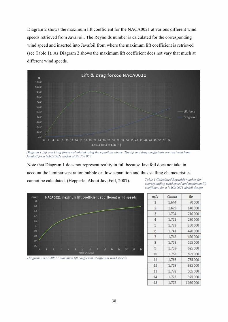
= ∗ ℎ where c is the length of the chord and h is the height of the wing. Note that the wing area is calculated as the planform area (as seen from above) looking along the “lift” direction and NOT the whole wing surface area (National Aeronautics and Space Administration, 2016). With these equations the lift the sail produces can be calculated (using the generous CL as 0.8 for the sails). The wing can then be designed to match or exceed the lifting forces the sail produces by using the data/programs available. The sail area for the Mini 12 is calculated to be 8.2 m2. By using the equations above the lift this sail creates is calculated to be approximately 100 N at a wind speed of 5 m/s. This is a generous estimate, however this will be the reference lift which the wing will be designed after. The main wing is designed as a NACA0021 with a chord length of 1 m and a height of 3.5 m. The NACA0021 is chosen as the main wing design because of its good lift and drag properties which can be seen in Diagram 1 and in Annex 1 (the choosing of the wing design and the program JavaFoil will be discussed more in detail in the chapter 7.2.1). The Reynolds number is calculated to be ca. 350.000 for a wing with the chord length of 1m and a characteristics length of 1.05m (NACA0021) at the wind velocity of 5 m/s and at the air density of 1.204 kg/m3. At a Reynolds number 350.000 the maximum lift coefficient retrieved form Javafoil is 1.732 (see Table 1) which gives us a calculated max lift of 91.2 N with a drag of ca. 13 N at 21° incidence (see Diagram 1). This wing creates almost as much thrust as the overly generous assumption about the soft sails. The drag these airfoils (main and tail wing section) create is very little at effective angles of attack.
38
Diagram 2 shows the maximum lift coefficient for the NACA0021 at various different wind speeds retrieved from JavaFoil. The Reynolds number is calculated for the corresponding wind speed and inserted into Javafoil from where the maximum lift coefficient is retrieved (see Table 1). As Diagram 2 shows the maximum lift coefficient does not vary that much at different wind speeds.
Note that Diagram 1 does not represent reality in full because Javafoil does not take in account the laminar separation bubble or flow separation and thus stalling characteristics cannot be calculated. (Hepperle, About JavaFoil, 2007).
Diagram 2 NACA0021 maximum lift coefficient at different wind speeds
Table 1 Calculated Reynolds number for corresponding wind speed and maximum lift coefficient for a NACA0021 airfoil design
Diagram 1 Lift and Drag forces calculated using the equations above. The lift and drag coefficients are retrieved from Javafoil for a NACA0021 airfoil at Re 350 000
39
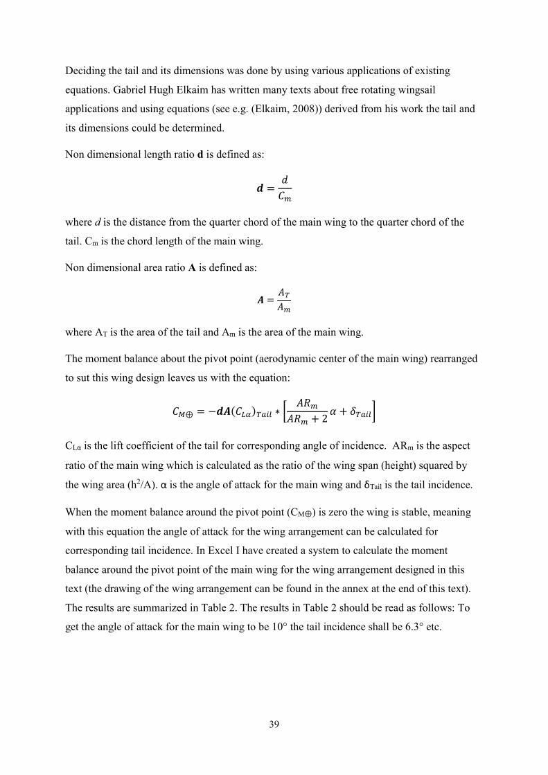
Deciding the tail and its dimensions was done by using various applications of existing equations. Gabriel Hugh Elkaim has written many texts about free rotating wingsail applications and using equations (see e.g. (Elkaim, 2008)) derived from his work the tail and its dimensions could be determined. Non dimensional length ratio d is defined as:
=
where d is the distance from the quarter chord of the main wing to the quarter chord of the tail. Cm is the chord length of the main wing. Non dimensional area ratio A is defined as:
=
where AT is the area of the tail and Am is the area of the main wing. The moment balance about the pivot point (aerodynamic center of the main wing) rearranged to sut this wing design leaves us with the equation:
⊕ = − ( ) ∗ + 2 +
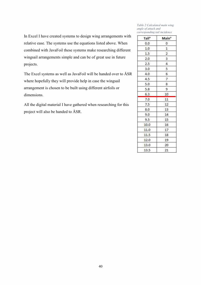
CLα is the lift coefficient of the tail for corresponding angle of incidence. ARm is the aspect ratio of the main wing which is calculated as the ratio of the wing span (height) squared by the wing area (h2/A). α is the angle of attack for the main wing and δTail is the tail incidence. When the moment balance around the pivot point (CM⊕) is zero the wing is stable, meaning with this equation the angle of attack for the wing arrangement can be calculated for corresponding tail incidence. In Excel I have created a system to calculate the moment balance around the pivot point of the main wing for the wing arrangement designed in this text (the drawing of the wing arrangement can be found in the annex at the end of this text). The results are summarized in Table 2. The results in Table 2 should be read as follows: To get the angle of attack for the main wing to be 10° the tail incidence shall be 6.3° etc.
40
In Excel I have created systems to design wing arrangements with relative ease. The systems use the equations listed above. When combined with JavaFoil these systems make researching different wingsail arrangements simple and can be of great use in future projects. The Excel systems as well as JavaFoil will be handed over to ÅSR where hopefully they will provide help in case the wingsail arrangement is chosen to be built using different airfoils or dimensions. All the digital material I have gathered when researching for this project will also be handed to ÅSR.
Table 2 Calculated main wing angle of attack and corresponding tail incidence
41
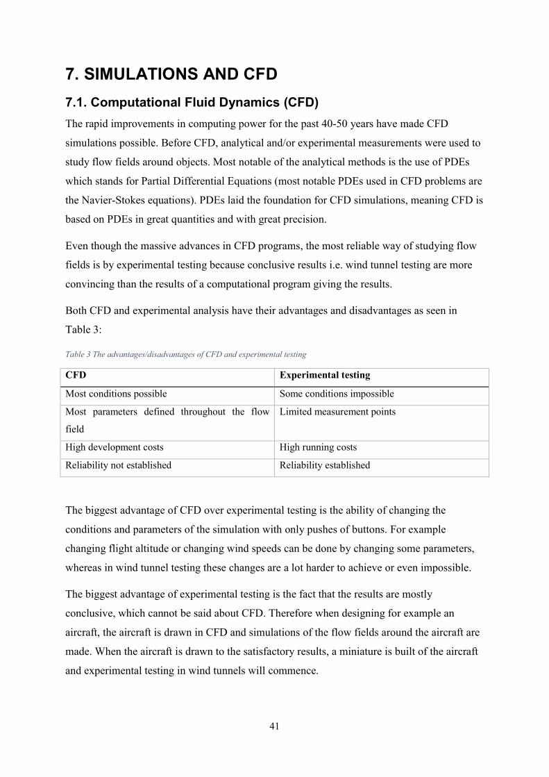
7. SIMULATIONS AND CFD 7.1. Computational Fluid Dynamics (CFD) The rapid improvements in computing power for the past 40-50 years have made CFD simulations possible. Before CFD, analytical and/or experimental measurements were used to study flow fields around objects. Most notable of the analytical methods is the use of PDEs which stands for Partial Differential Equations (most notable PDEs used in CFD problems are the Navier-Stokes equations). PDEs laid the foundation for CFD simulations, meaning CFD is based on PDEs in great quantities and with great precision. Even though the massive advances in CFD programs, the most reliable way of studying flow fields is by experimental testing because conclusive results i.e. wind tunnel testing are more convincing than the results of a computational program giving the results. Both CFD and experimental analysis have their advantages and disadvantages as seen in Table 3: Table 3 The advantages/disadvantages of CFD and experimental testing CFD Experimental testing Most conditions possible Some conditions impossible Most parameters defined throughout the flow field
Limited measurement points
High development costs High running costs Reliability not established Reliability established The biggest advantage of CFD over experimental testing is the ability of changing the conditions and parameters of the simulation with only pushes of buttons. For example changing flight altitude or changing wind speeds can be done by changing some parameters, whereas in wind tunnel testing these changes are a lot harder to achieve or even impossible. The biggest advantage of experimental testing is the fact that the results are mostly conclusive, which cannot be said about CFD. Therefore when designing for example an aircraft, the aircraft is drawn in CFD and simulations of the flow fields around the aircraft are made. When the aircraft is drawn to the satisfactory results, a miniature is built of the aircraft and experimental testing in wind tunnels will commence.
42
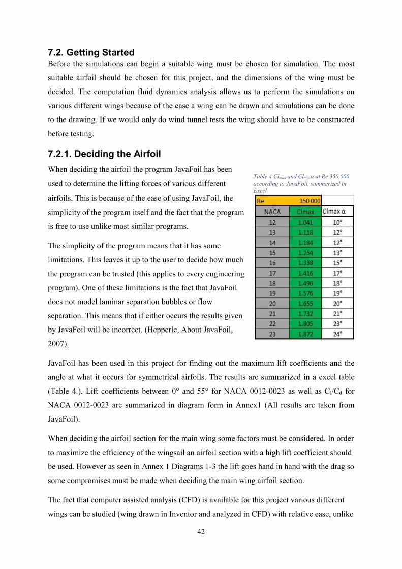
Table 4 Clmax and Clmaxα at Re 350.000 according to JavaFoil, summarized in Excel
7.2. Getting Started Before the simulations can begin a suitable wing must be chosen for simulation. The most suitable airfoil should be chosen for this project, and the dimensions of the wing must be decided. The computation fluid dynamics analysis allows us to perform the simulations on various different wings because of the ease a wing can be drawn and simulations can be done to the drawing. If we would only do wind tunnel tests the wing should have to be constructed before testing. 7.2.1. Deciding the Airfoil When deciding the airfoil the program JavaFoil has been used to determine the lifting forces of various different airfoils. This is because of the ease of using JavaFoil, the simplicity of the program itself and the fact that the program is free to use unlike most similar programs. The simplicity of the program means that it has some limitations. This leaves it up to the user to decide how much the program can be trusted (this applies to every engineering program). One of these limitations is the fact that JavaFoil does not model laminar separation bubbles or flow separation. This means that if either occurs the results given by JavaFoil will be incorrect. (Hepperle, About JavaFoil, 2007). JavaFoil has been used in this project for finding out the maximum lift coefficients and the angle at what it occurs for symmetrical airfoils. The results are summarized in a excel table (Table 4.). Lift coefficients between 0° and 55° for NACA 0012-0023 as well as Cl/Cd for NACA 0012-0023 are summarized in diagram form in Annex1 (All results are taken from JavaFoil). When deciding the airfoil section for the main wing some factors must be considered. In order to maximize the efficiency of the wingsail an airfoil section with a high lift coefficient should be used. However as seen in Annex 1 Diagrams 1-3 the lift goes hand in hand with the drag so some compromises must be made when deciding the main wing airfoil section. The fact that computer assisted analysis (CFD) is available for this project various different wings can be studied (wing drawn in Inventor and analyzed in CFD) with relative ease, unlike
43
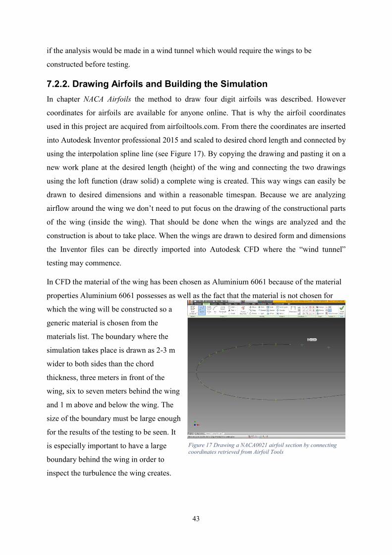
Figure 17 Drawing a NACA0021 airfoil section by connecting coordinates retrieved from Airfoil Tools
if the analysis would be made in a wind tunnel which would require the wings to be constructed before testing. 7.2.2. Drawing Airfoils and Building the Simulation In chapter NACA Airfoils the method to draw four digit airfoils was described. However coordinates for airfoils are available for anyone online. That is why the airfoil coordinates used in this project are acquired from airfoiltools.com. From there the coordinates are inserted into Autodesk Inventor professional 2015 and scaled to desired chord length and connected by using the interpolation spline line (see Figure 17). By copying the drawing and pasting it on a new work plane at the desired length (height) of the wing and connecting the two drawings using the loft function (draw solid) a complete wing is created. This way wings can easily be drawn to desired dimensions and within a reasonable timespan. Because we are analyzing airflow around the wing we don’t need to put focus on the drawing of the constructional parts of the wing (inside the wing). That should be done when the wings are analyzed and the construction is about to take place. When the wings are drawn to desired form and dimensions the Inventor files can be directly imported into Autodesk CFD where the “wind tunnel” testing may commence. In CFD the material of the wing has been chosen as Aluminium 6061 because of the material properties Aluminium 6061 possesses as well as the fact that the material is not chosen for which the wing will be constructed so a generic material is chosen from the materials list. The boundary where the simulation takes place is drawn as 2-3 m wider to both sides than the chord thickness, three meters in front of the wing, six to seven meters behind the wing and 1 m above and below the wing. The size of the boundary must be large enough for the results of the testing to be seen. It is especially important to have a large boundary behind the wing in order to inspect the turbulence the wing creates.
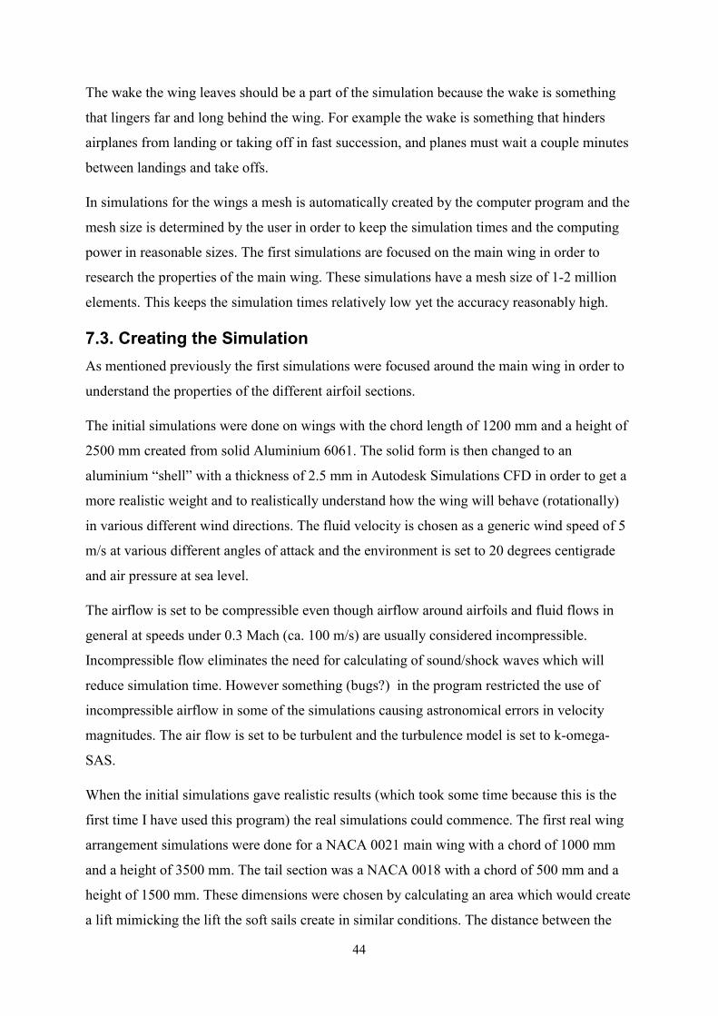
44
The wake the wing leaves should be a part of the simulation because the wake is something that lingers far and long behind the wing. For example the wake is something that hinders airplanes from landing or taking off in fast succession, and planes must wait a couple minutes between landings and take offs. In simulations for the wings a mesh is automatically created by the computer program and the mesh size is determined by the user in order to keep the simulation times and the computing power in reasonable sizes. The first simulations are focused on the main wing in order to research the properties of the main wing. These simulations have a mesh size of 1-2 million elements. This keeps the simulation times relatively low yet the accuracy reasonably high. 7.3. Creating the Simulation As mentioned previously the first simulations were focused around the main wing in order to understand the properties of the different airfoil sections. The initial simulations were done on wings with the chord length of 1200 mm and a height of 2500 mm created from solid Aluminium 6061. The solid form is then changed to an aluminium “shell” with a thickness of 2.5 mm in Autodesk Simulations CFD in order to get a more realistic weight and to realistically understand how the wing will behave (rotationally) in various different wind directions. The fluid velocity is chosen as a generic wind speed of 5 m/s at various different angles of attack and the environment is set to 20 degrees centigrade and air pressure at sea level. The airflow is set to be compressible even though airflow around airfoils and fluid flows in general at speeds under 0.3 Mach (ca. 100 m/s) are usually considered incompressible. Incompressible flow eliminates the need for calculating of sound/shock waves which will reduce simulation time. However something (bugs?) in the program restricted the use of incompressible airflow in some of the simulations causing astronomical errors in velocity magnitudes. The air flow is set to be turbulent and the turbulence model is set to k-omega-SAS. When the initial simulations gave realistic results (which took some time because this is the first time I have used this program) the real simulations could commence. The first real wing arrangement simulations were done for a NACA 0021 main wing with a chord of 1000 mm and a height of 3500 mm. The tail section was a NACA 0018 with a chord of 500 mm and a height of 1500 mm. These dimensions were chosen by calculating an area which would create a lift mimicking the lift the soft sails create in similar conditions. The distance between the
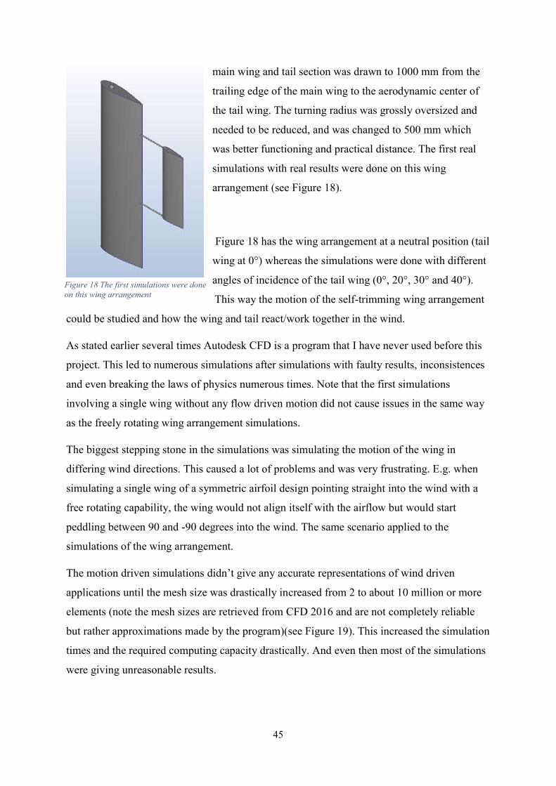
45
main wing and tail section was drawn to 1000 mm from the trailing edge of the main wing to the aerodynamic center of the tail wing. The turning radius was grossly oversized and needed to be reduced, and was changed to 500 mm which was better functioning and practical distance. The first real simulations with real results were done on this wing arrangement (see Figure 18). Figure 18 has the wing arrangement at a neutral position (tail wing at 0°) whereas the simulations were done with different angles of incidence of the tail wing (0°, 20°, 30° and 40°). This way the motion of the self-trimming wing arrangement
could be studied and how the wing and tail react/work together in the wind. As stated earlier several times Autodesk CFD is a program that I have never used before this project. This led to numerous simulations after simulations with faulty results, inconsistences and even breaking the laws of physics numerous times. Note that the first simulations involving a single wing without any flow driven motion did not cause issues in the same way as the freely rotating wing arrangement simulations. The biggest stepping stone in the simulations was simulating the motion of the wing in differing wind directions. This caused a lot of problems and was very frustrating. E.g. when simulating a single wing of a symmetric airfoil design pointing straight into the wind with a free rotating capability, the wing would not align itself with the airflow but would start peddling between 90 and -90 degrees into the wind. The same scenario applied to the simulations of the wing arrangement. The motion driven simulations didn’t give any accurate representations of wind driven applications until the mesh size was drastically increased from 2 to about 10 million or more elements (note the mesh sizes are retrieved from CFD 2016 and are not completely reliable but rather approximations made by the program)(see Figure 19). This increased the simulation times and the required computing capacity drastically. And even then most of the simulations were giving unreasonable results.
Figure 18 The first simulations were done on this wing arrangement
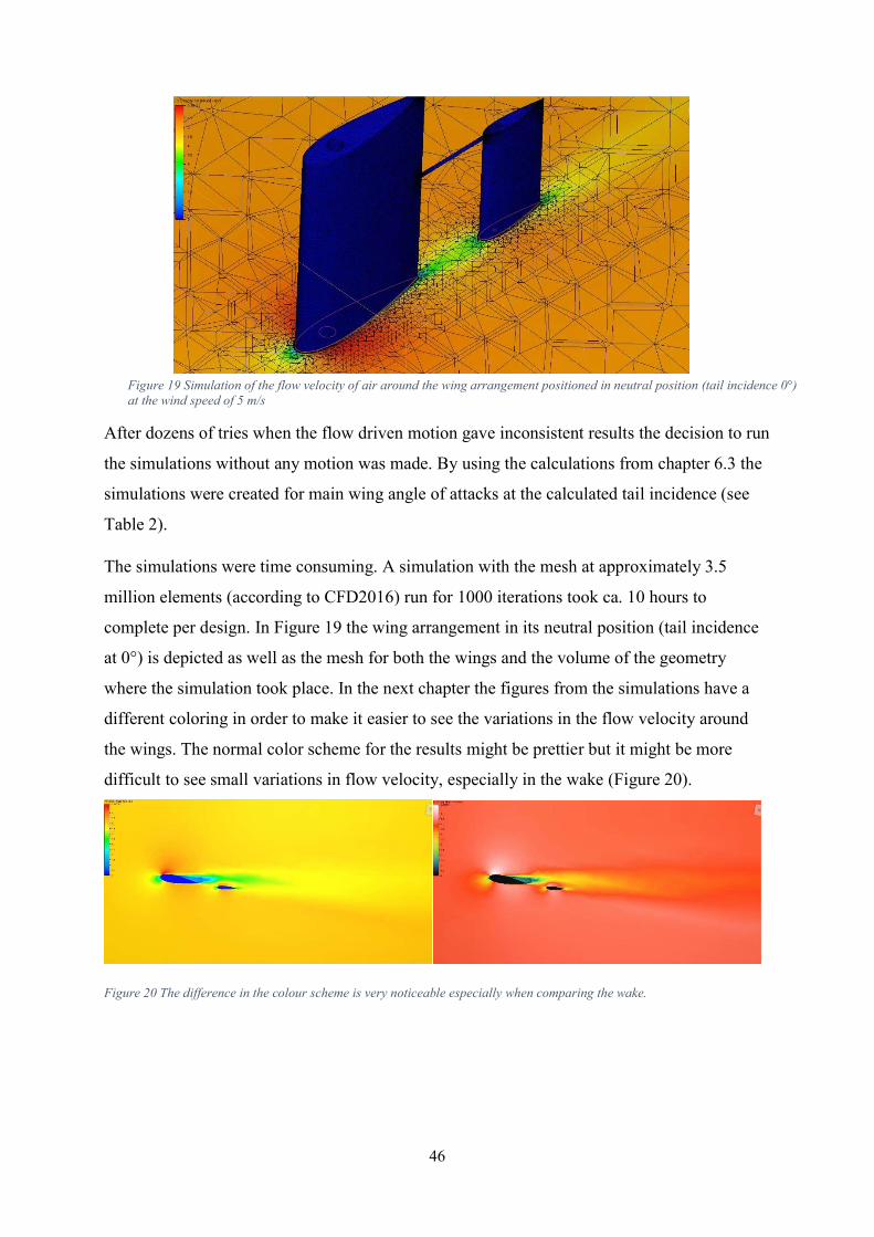
46
After dozens of tries when the flow driven motion gave inconsistent results the decision to run the simulations without any motion was made. By using the calculations from chapter 6.3 the simulations were created for main wing angle of attacks at the calculated tail incidence (see Table 2). The simulations were time consuming. A simulation with the mesh at approximately 3.5 million elements (according to CFD2016) run for 1000 iterations took ca. 10 hours to complete per design. In Figure 19 the wing arrangement in its neutral position (tail incidence at 0°) is depicted as well as the mesh for both the wings and the volume of the geometry where the simulation took place. In the next chapter the figures from the simulations have a different coloring in order to make it easier to see the variations in the flow velocity around the wings. The normal color scheme for the results might be prettier but it might be more difficult to see small variations in flow velocity, especially in the wake (Figure 20).
Figure 20 The difference in the colour scheme is very noticeable especially when comparing the wake.
Figure 19 Simulation of the flow velocity of air around the wing arrangement positioned in neutral position (tail incidence 0°) at the wind speed of 5 m/s
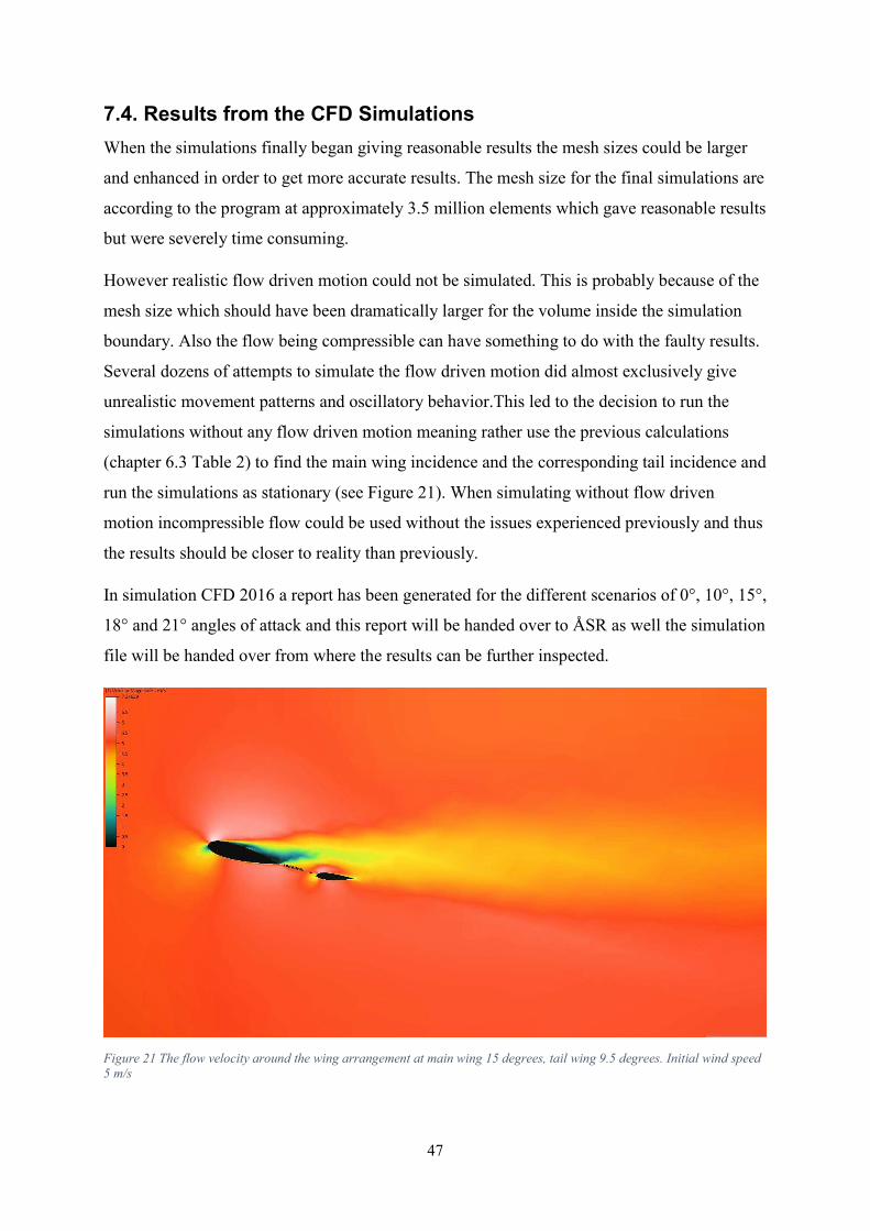
47
7.4. Results from the CFD Simulations When the simulations finally began giving reasonable results the mesh sizes could be larger and enhanced in order to get more accurate results. The mesh size for the final simulations are according to the program at approximately 3.5 million elements which gave reasonable results but were severely time consuming. However realistic flow driven motion could not be simulated. This is probably because of the mesh size which should have been dramatically larger for the volume inside the simulation boundary. Also the flow being compressible can have something to do with the faulty results. Several dozens of attempts to simulate the flow driven motion did almost exclusively give unrealistic movement patterns and oscillatory behavior.This led to the decision to run the simulations without any flow driven motion meaning rather use the previous calculations (chapter 6.3 Table 2) to find the main wing incidence and the corresponding tail incidence and run the simulations as stationary (see Figure 21). When simulating without flow driven motion incompressible flow could be used without the issues experienced previously and thus the results should be closer to reality than previously. In simulation CFD 2016 a report has been generated for the different scenarios of 0°, 10°, 15°, 18° and 21° angles of attack and this report will be handed over to ÅSR as well the simulation file will be handed over from where the results can be further inspected.
Figure 21 The flow velocity around the wing arrangement at main wing 15 degrees, tail wing 9.5 degrees. Initial wind speed 5 m/s
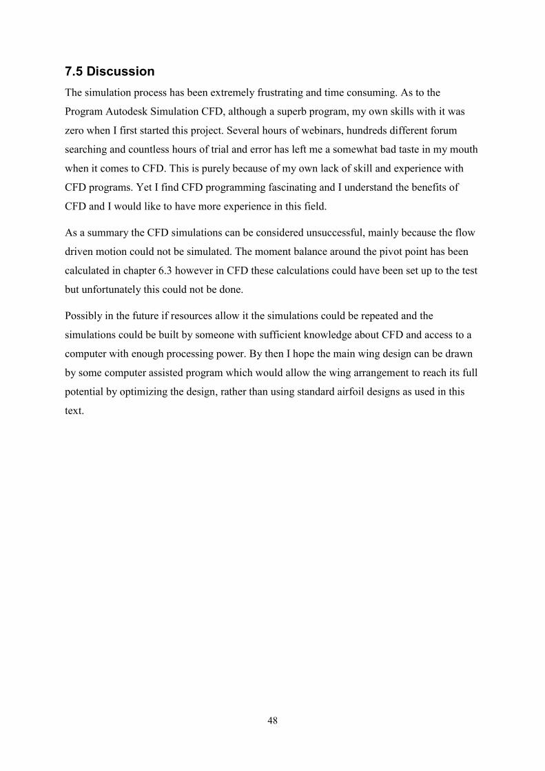
48
7.5 Discussion The simulation process has been extremely frustrating and time consuming. As to the Program Autodesk Simulation CFD, although a superb program, my own skills with it was zero when I first started this project. Several hours of webinars, hundreds different forum searching and countless hours of trial and error has left me a somewhat bad taste in my mouth when it comes to CFD. This is purely because of my own lack of skill and experience with CFD programs. Yet I find CFD programming fascinating and I understand the benefits of CFD and I would like to have more experience in this field. As a summary the CFD simulations can be considered unsuccessful, mainly because the flow driven motion could not be simulated. The moment balance around the pivot point has been calculated in chapter 6.3 however in CFD these calculations could have been set up to the test but unfortunately this could not be done. Possibly in the future if resources allow it the simulations could be repeated and the simulations could be built by someone with sufficient knowledge about CFD and access to a computer with enough processing power. By then I hope the main wing design can be drawn by some computer assisted program which would allow the wing arrangement to reach its full potential by optimizing the design, rather than using standard airfoil designs as used in this text.
49
8. PRACTICAL ISSUES AND SOLUTIONS This section of the project is very hypothetical and includes many ifs, when’s and what’s. This is mainly because the decision of building the wing is not made and therefore the future of the wing arrangement for the Mini 12 is cloudy. This chapter however will provide possible solutions to some of the problems that may occur in the stage of planning and manufacturing the wing arrangement, if the decision for a wingsail to propel the Mini 12 should be made. 8.1. Aerodynamic and Mass Center Alignment The aerodynamic center on a symmetric airfoil is located precisely one quarter of the chord length from the leading edge of the airfoil. This is the point where the wing should be connected to the mast in order to ensure the self-trimming ability of the wing arrangement. The mass center however is located further back because a tailed wing configuration is tail heavy. This leads to the need of ballast by some form in front of the wing to bring the mass center in line with the aerodynamic center and this way ensuring the free rotating capability of the wing. There are numerous different ballasting methods that can be used. The main issue with applying extra weight to a boat of any kind is the increased mass of the boat and in the case of applying ballast high up the boat (compared to normal cargo) is the heightened mass center of the boat itself. If the mass center of the boat is too high the boat will capsize or be unable to recover from big heeling forces. Having the mass center of the boat as low as possible is crucial to ensure the safety of operationality of any boat, be it a canoe or an aircraft carrier. Figure 22 demonstrates three different methods of ballast implementation to a tailed wing arrangement.
Figure 22 Three different methods of implementing ballast in front of a tailed wing. The aerodynamic center is located in the center of the mast and is marked with A.C, the external mass is marked with M
50
Number 1 is a simple counter weight in front of the wing. In this sketch the position of the ballast for method number 1 is at half the height of the main wing. Number 2 is a bulb at the root of the main wing which can be designed for maximum aerodynamic effect. Number 3 is a simple counterweight located at the root of the wing in order to keep the mass centre of the boat as low as possible. The desire to keep the mass center as low as possible makes Number 1 undesirable, leaving number 2 and 3 to be considered possible ballast methods. Number 3 is a simple counter weight suspended in front of the wing as low as possible on the wing without causing problems when the wing rotates freely 360°. Design-wise number 3 is similar to number 1 with the exception of the height placement of the external mass. Number 2 is the optimal ballasting method because the bulb can be designed in a way that it doesn’t contribute negatively aerodynamics-wise. This however requires aerodynamic research of different designs of the bulb. Another advantage achieved with Number 2 is the fact that the counterweight is cased inside the wing (the bulb is a part of the wing). This opens up different uses for the ballast in the wing in the future. An example of this is that if in the future the wing would be fitted with solar panels, batteries that store the electrical energy could be used as ballast in the bulb thus eliminating the need for both batteries and ballast leading to decreased mass onboard the boat. Should the steering method for the tail wing be electrical then possibly the bulb in the number 2 solution could act as housing for electrical components, which would act as ballast. If the electrical components steering the tail could have a wireless connection to the main computer inside the hull of the boat no wiring what so ever would be needed to steer the wing. These kinds of solutions should be given some consideration before and during construction, until then only speculations can be made. Number 2 is the optimal and therefore should possibly be used in future wing designs, should there be some. However number 3 should probably be used as the initial ballasting method for the Mini 12 because of its simplicity and the ease of modification (easy to calculate the needed mass required and to apply it). In order to minimize the aerodynamic drag caused by number 3 the form of the counterweight can be designed to any shape desirable (i.e. as an airfoil). The thing with all these ballast methods is that the wing must be constructed before the mass and placement of the ballast can be calculated. The weight and the mass center of the wing must be known and according to that the mass and position of the ballast can be accurately
51
placed in order to align the mass center of the wing arrangement with the aerodynamic center. By suspending the wing on bearings the rotation will be close to frictionless (this is possible only if the weight distribution is in a state of equilibrium at the center of rotation). 8.2. Steering the Wing The biggest issue with the self-trimming wing is the steering of the tail section which in turn “steers” the main wing3. The problem emerged as soon as the decision of the self-trimming wing was made. Using a single wing solution was the initial plan for this project but the need for a motor of sorts to constantly trim the wing quickly eliminated this solution. The need of a motor to constantly work as a means to trim the wing would not be energy efficient, which is the most important thing in autonomous sailing. The steering methods are limited to a couple of different methods, namely electric/hydraulic and mechanical. It all comes down to the decision of whether the mast is a part of the wing and rotates freely, or if the wing rotates around the mast. This was not clear in the beginning of this project but the best option was quickly decided upon when the pros and cons were discussed for these two options. The wing and mast rotating creates various problems. Firstly the mast would have to be resting on some form of bearing shell. This creates various different problems for raising/lowering the mast but also would increase the mass of the boat because of the need for a large bearing shell. The biggest issue however is the wiring, not only for steering but also the different components located on top of the mast (i.e. the wind sensor and GPS). When the wing rotates around the mast the issue around the wiring for the components on top of the mast can be easily solved. E.g. this can be done simply by having the wiring go through the inside of the mast all the way down inside the boat. That only leaves the issue of how to steer the tail wing.
3 The steering of the wing has been the biggest question on my mind since the beginning of this project. These past months not one day has gone by without me thinking about a possible solution to this problem.
52
8.2.1. Electric/Hydraulic Steering The biggest issue with electric/hydraulic steering of the tail wing is the free rotating capability of the wing arrangement. Wiring and piping don’t cooperate with the thought of being freely rotational infinitely. This is an especially difficult issue if hydraulic steering would be chosen as the means of steering the tail wing. The need for hydraulic pumps, tanks and general issues regarding piping eliminates this steering method for this project before given any serious consideration. Electric steering has been the most prominent method for a large part of this project, however, some issues still need solutions. As previously mentioned the free rotating capability of the wing arrangement makes wiring difficult for electrical components in the wing (rotating connectors must be used). The classification of the components to be used in this project must be of a high water resistance to ensure functionality of all components even if they come in contact with saltwater. This can prove to be problematic when searching for rotating electrical connectors within a reasonable price range. If components like these would be found, electric steering is a very plausible solution and should be seriously considered as the main steering method of the wing arrangement. 8.2.2. Mechanical Steering There is a mechanical method out on the market to steer a self-trimming wingsail, however, it is a patented steering method which automatically makes it unusable for this project. This is unless the patent holder would be willing to have his steering method implemented to the Mini 12 which would most likely be good advertisement for his steering method. If the patent holder is interested in a collaboration of sorts would be up to him entirely. The time restraints for this text hinders the author to spare any thought on a patented solution (it is pointless to try and reinvent the wheel because someone has it patented).
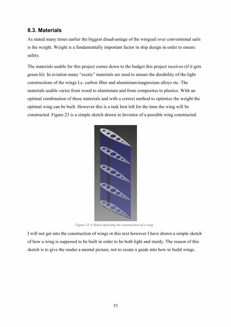
53
8.3. Materials As stated many times earlier the biggest disadvantage of the wingsail over conventional sails is the weight. Weight is a fundamentally important factor in ship design in order to ensure safety. The materials usable for this project comes down to the budget this project receives (if it gets green lit). In aviation many “exotic” materials are used to ensure the durability of the light constructions of the wings I.e. carbon fiber and aluminium/magnesium alloys etc. The materials usable varies from wood to aluminium and from composites to plastics. With an optimal combination of these materials and with a correct method to optimize the weight the optimal wing can be built. However this is a task best left for the time the wing will be constructed. Figure 23 is a simple sketch drawn in Inventor of a possible wing constructed.
I will not get into the construction of wings in this text however I have drawn a simple sketch of how a wing is supposed to be built in order to be both light and sturdy. The reason of this sketch is to give the reader a mental picture, not to create a guide into how to build wings.
Figure 23 A sketch depicting the construction of a wing
54
8.4 Conclusion Many of the above mentioned issues could be solved with a very large budget and this applies to almost everything. However in reality projects like this often face obstacles that come with the need to be economically efficient. This puts limitations on components, materials, research and development which in turn can affect the final product. This can discourage the people involved to drop the project or it can be embraced as a challenge to be taken head on. Knowing the people involved the latter is the better option. These problems will have to be dealt with by the people who will be in charge of continuing this project, and bringing it to its end. In conclusion the issues that come with the wingsail are numerous and the solutions are nearly impossible to be provided at this early stage. The issues (ballast, steering, material etc.) shall be dealt with in the construction phase. Even though this chapter consists mostly of ifs and whens, hopefully some insight has been given into how some of the issues can be dealt with.
55
9. SUMMARY At a very early stage, maybe even before the project started it was clear that a wingsail application would be suitable for the Mini 12 because of wingsails superior efficiency. This claim is supported by the simple calculations made using the equations usually used to calculate the lifting forces of aircraft. The next major issues this project faced was the effective area optimizing of the tail wing and tail sections to ensure the self-trimming capability of the wing arrangement. A major part of this project was the CFD simulations witch proved to be more frustrating and time consuming than I could have ever anticipated. Granted the simulations haven’t proved to be the optimal for wind scenarios like the ones simulated (compressible/incompressible) in this project, but the foundations are there for the next person who decides to continue this project. Hopefully if the need to go back to CFD would arise then the simulations would be run by a computer with superior computing capabilities compared to my personal computer which has been running for weeks from morning to night at 100% processing power. Autodesk simulation CFD 2016 has a report generator feature which I have used to compile the results from the simulations. This report is very extensive and large, so large that it is not usable in whole to be inserted in this text (around 40 pages). The complete results will be handed over to ÅSR along with all the tools used to design the wing arrangement. The simulation file will also be handed over to ÅSR from where a lot more data can be studied which is not written in the report generated by CFD. All in all a wingsail arrangement would be suitable for the Mini 12 if the issues regarding steering the tail section, finding the mass balance about the pivot point and construction of a light and sturdy design can be solved. I don’t doubt for a second that these issues can be solved by the people of ÅSR as well as future students at Åland University of Applied Sciences and I hope to read about the success of ÅSR in the world of robotic sailing in the future. Hopefully I can say that I have played a part in the ground work behind the wingsail onboard one of the robots. I’m looking forward to that day.
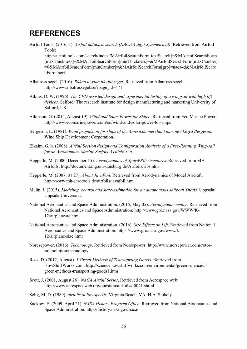
56
REFERENCES Airfoil Tools. (2016, 1). Airfoil database search (NACA 4 digit Symmetrical). Retrieved from Airfoil
Tools: http://airfoiltools.com/search/index?MAirfoilSearchForm[textSearch]=&MAirfoilSearchForm[maxThickness]=&MAirfoilSearchForm[minThickness]=&MAirfoilSearchForm[maxCamber]=0&MAirfoilSearchForm[minCamber]=&MAirfoilSearchForm[grp]=naca4d&MAirfoilSearchForm[sort]
Albatross segel. (2016). Räkna ut ytan på ditt segel. Retrieved from Albatross segel: http://www.albatrossegel.se/?page_id=471
Atkins, D. W. (1996). The CFD assisted design and experimental testing of a wingsail with high lift devices. Salford: The research institute for design manufacturing and marketing University of Salford, UK.
Atkinson, G. (2015, August 19). Wind and Solar Power for Ships . Retrieved from Eco Marine Power: http://www.ecomarinepower.com/en/wind-and-solar-power-for-ships
Bergeson, L. (1981). Wind propulsion for ships of the American merchant marine / Lloyd Bergeson. Wind Ship Development Corporation.
Elkaim, G. h. (2008). Airfoil Section design and Configuration Analysis of a Free-Rotating Wing-sail for an Autonomous Marine Surface Vehicle. CA.
Hepperle, M. (2000, December 15). Aerodynamics of Spar&Rib structures. Retrieved from MH Airfoils: http://document.ihg.uni-duisburg.de/Airfoils/ribs.htm
Hepperle, M. (2007, 01 27). About JavaFoil. Retrieved from Aerodynamics of Model Aircraft: http://www.mh-aerotools.de/airfoils/javafoil.htm
Melin, J. (2015). Modeling, control and state-estimation for an autonomous sailboat Thesis. Uppsala: Uppsala Universitet.
National Aeronautics and Space Administration. (2015, May 05). Aerodynamic center. Retrieved from National Aeronautics and Space Administration: http://www.grc.nasa.gov/WWW/K-12/airplane/ac.html
National Aeronautics and Space Administration. (2016). Size Effects on Lift. Retrieved from National Aeronautics and Space Administration: https://www.grc.nasa.gov/www/k-12/airplane/size.html
Noresepower. (2016). Technology. Retrieved from Norsepower: http://www.norsepower.com/rotor-sail-solution/technology
Ross, D. (2012, August). 5 Green Methods of Transoprting Goods. Retrieved from HowStuffWorks.com: http://science.howstuffworks.com/environmental/green-science/5-green-methods-transporting-goods1.htm
Scott, J. (2001, August 26). NACA Airfoil Series. Retrieved from Aerospace web: http://www.aerospaceweb.org/question/airfoils/q0041.shtml
Selig, M. D. (1989). airfoils at low speeds. Virginia Beach, VA: H.A. Stokely. Suckow, E. (2009, April 21). NASA History Program Office. Retrieved from National Aeronautics and
Space Administration: http://history.nasa.gov/naca/
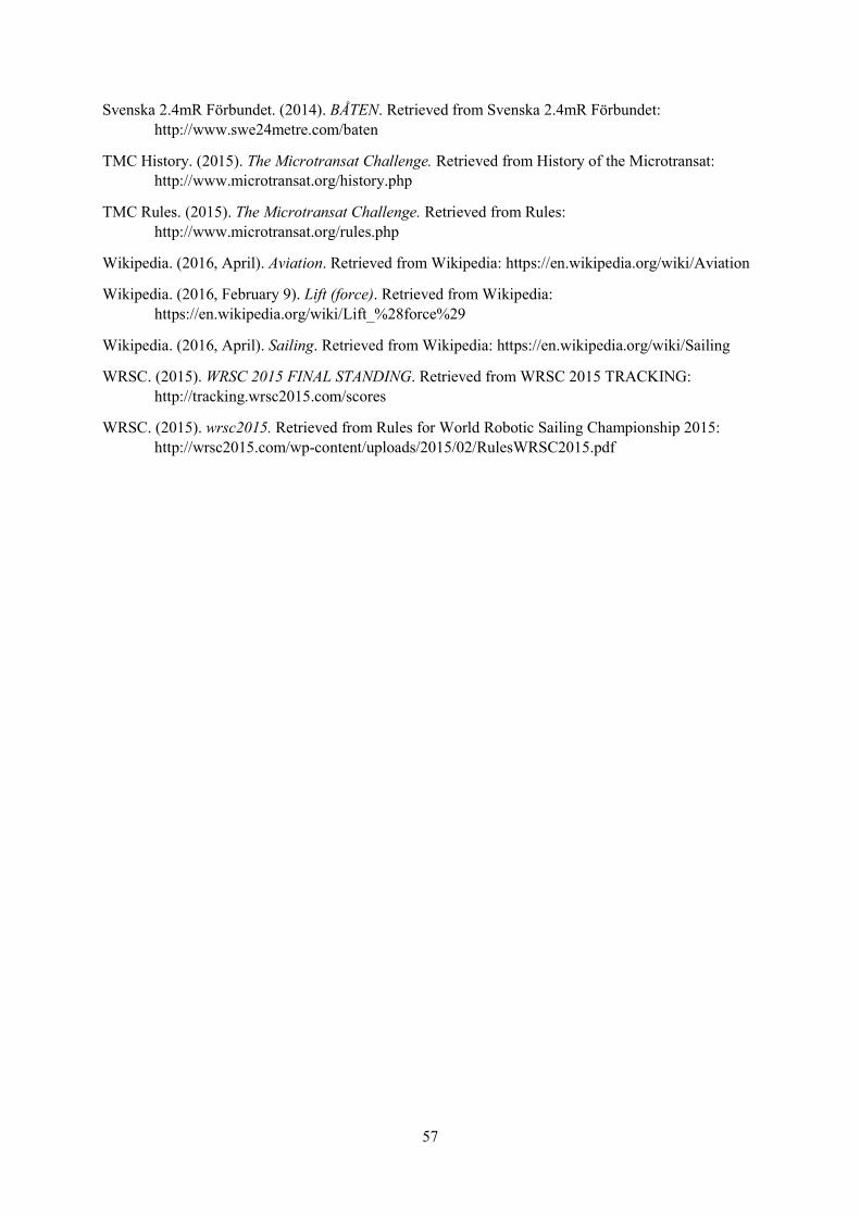
57
Svenska 2.4mR Förbundet. (2014). BÅTEN. Retrieved from Svenska 2.4mR Förbundet: http://www.swe24metre.com/baten
TMC History. (2015). The Microtransat Challenge. Retrieved from History of the Microtransat: http://www.microtransat.org/history.php
TMC Rules. (2015). The Microtransat Challenge. Retrieved from Rules: http://www.microtransat.org/rules.php
Wikipedia. (2016, April). Aviation. Retrieved from Wikipedia: https://en.wikipedia.org/wiki/Aviation Wikipedia. (2016, February 9). Lift (force). Retrieved from Wikipedia:
https://en.wikipedia.org/wiki/Lift_%28force%29 Wikipedia. (2016, April). Sailing. Retrieved from Wikipedia: https://en.wikipedia.org/wiki/Sailing WRSC. (2015). WRSC 2015 FINAL STANDING. Retrieved from WRSC 2015 TRACKING:
http://tracking.wrsc2015.com/scores WRSC. (2015). wrsc2015. Retrieved from Rules for World Robotic Sailing Championship 2015:
http://wrsc2015.com/wp-content/uploads/2015/02/RulesWRSC2015.pdf
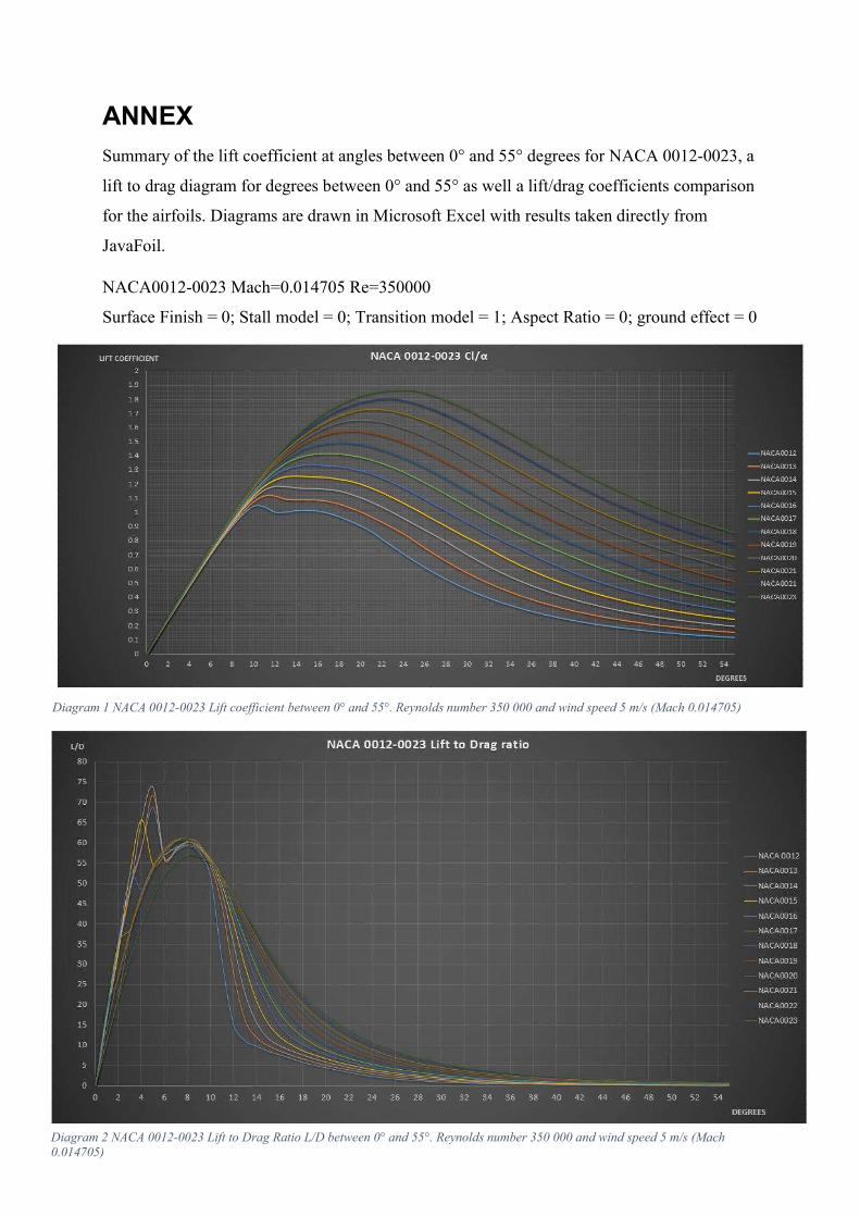
58
Diagram 1 NACA 0012-0023 Lift coefficient between 0° and 55°. Reynolds number 350 000 and wind speed 5 m/s (Mach 0.014705)
ANNEX Summary of the lift coefficient at angles between 0° and 55° degrees for NACA 0012-0023, a lift to drag diagram for degrees between 0° and 55° as well a lift/drag coefficients comparison for the airfoils. Diagrams are drawn in Microsoft Excel with results taken directly from JavaFoil. NACA0012-0023 Mach=0.014705 Re=350000 Surface Finish = 0; Stall model = 0; Transition model = 1; Aspect Ratio = 0; ground effect = 0
Diagram 2 NACA 0012-0023 Lift to Drag Ratio L/D between 0° and 55°. Reynolds number 350 000 and wind speed 5 m/s (Mach 0.014705)
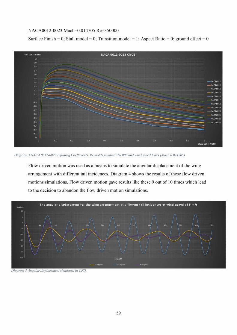
59
Diagram 3 NACA 0012-0023 Lift/drag Coefficients. Reynolds number 350 000 and wind speed 5 m/s (Mach 0.014705)
NACA0012-0023 Mach=0.014705 Re=350000 Surface Finish = 0; Stall model = 0; Transition model = 1; Aspect Ratio = 0; ground effect = 0
Flow driven motion was used as a means to simulate the angular displacement of the wing arrangement with different tail incidences. Diagram 4 shows the results of these flow driven motions simulations. Flow driven motion gave results like these 9 out of 10 times which lead to the decision to abandon the flow driven motion simulations.
Diagram 3 Angular displacement simulated in CFD.
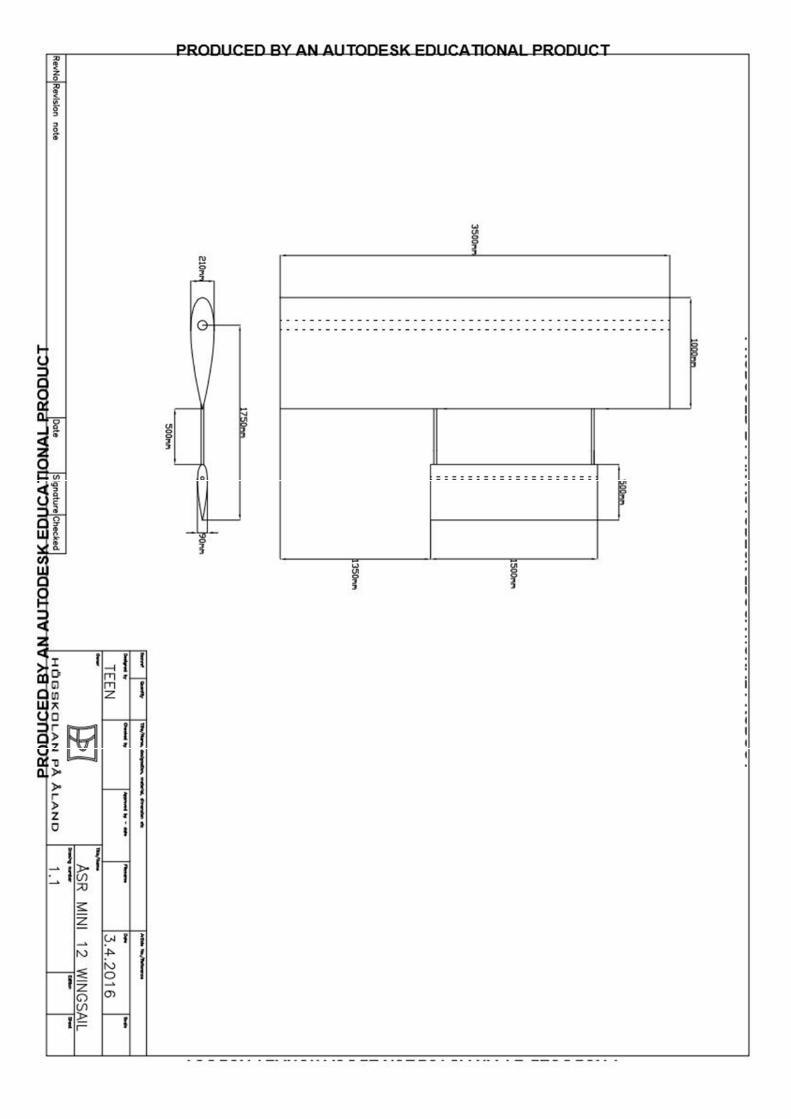
60