Embed Size (px)
Citation preview
Understanding the Cal Fire Solar Photovoltaic Installation
Guideline
Prepared for: Solar America Board for Codes and Standards (available soon at www.solarabcs.org)
Prepared by:
Brooks Engineering 873 Kells Circle
Vacaville, CA 95688 www.brooksolar.com
Version 1.0
August 2010
Understanding the Cal Fire Solar Photovoltaic Installation Guideline
ii
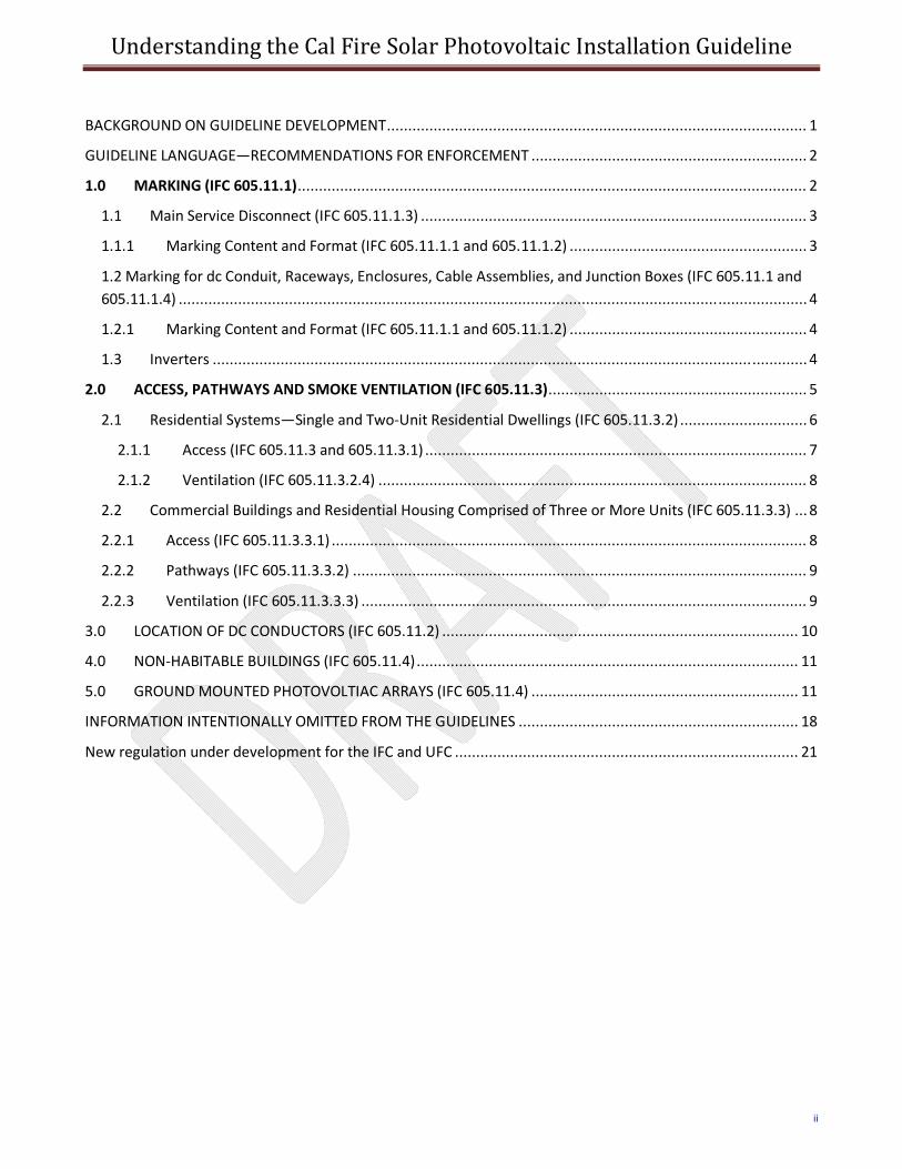
BACKGROUND ON GUIDELINE DEVELOPMENT ................................................................................................... 1
GUIDELINE LANGUAGE—RECOMMENDATIONS FOR ENFORCEMENT ................................................................. 2
1.0 MARKING (IFC 605.11.1) ........................................................................................................................ 2
1.1 Main Service Disconnect (IFC 605.11.1.3) ........................................................................................... 3
1.1.1 Marking Content and Format (IFC 605.11.1.1 and 605.11.1.2) ........................................................ 3
1.2 Marking for dc Conduit, Raceways, Enclosures, Cable Assemblies, and Junction Boxes (IFC 605.11.1 and 605.11.1.4) .................................................................................................................................................... 4
1.2.1 Marking Content and Format (IFC 605.11.1.1 and 605.11.1.2) ........................................................ 4
1.3 Inverters ............................................................................................................................................ 4
2.0 ACCESS, PATHWAYS AND SMOKE VENTILATION (IFC 605.11.3) ............................................................. 5
2.1 Residential Systems—Single and Two‐Unit Residential Dwellings (IFC 605.11.3.2) .............................. 6
2.1.1 Access (IFC 605.11.3 and 605.11.3.1) .......................................................................................... 7
2.1.2 Ventilation (IFC 605.11.3.2.4) ..................................................................................................... 8
2.2 Commercial Buildings and Residential Housing Comprised of Three or More Units (IFC 605.11.3.3) ... 8
2.2.1 Access (IFC 605.11.3.3.1) ................................................................................................................ 8
2.2.2 Pathways (IFC 605.11.3.3.2) ........................................................................................................... 9
2.2.3 Ventilation (IFC 605.11.3.3.3) ......................................................................................................... 9
3.0 LOCATION OF DC CONDUCTORS (IFC 605.11.2) .................................................................................... 10
4.0 NON‐HABITABLE BUILDINGS (IFC 605.11.4) .......................................................................................... 11
5.0 GROUND MOUNTED PHOTOVOLTIAC ARRAYS (IFC 605.11.4) ............................................................... 11
INFORMATION INTENTIONALLY OMITTED FROM THE GUIDELINES .................................................................. 18
New regulation under development for the IFC and UFC ................................................................................. 21
Understanding the Cal Fire Solar Photovoltaic Installation Guideline
1
BACKGROUND ON GUIDELINE DEVELOPMENT
INTRODUCTION—NEED FOR A DOCUMENT TO EXPLAIN THE GUIDELINE The California Department of Forestry and Fire Protection (Cal Fire), Office of the State Fire Marshal released a document entitled Solar Photovoltaic Installation Guideline on April 22, 2008. This document was the culmination of over six months of meetings held in partnership with interested local fire officials, building officials, and solar industry representatives. The purpose of the document was to provide the photovoltaic (PV) industry with information on how to install systems in a way that meets the objectives of both the PV industry and the Fire Service. The guideline includes direction for three main areas: 1) Marking of Conduit and Equipment; 2) Access, Pathways, and Smoke Ventilation; and, 3) Location of Direct Current (DC) Conductors. Information is provided for the application of these areas for residential and commercial construction. Although specific information is provided on what measures should be adequate for compliance in these three areas, there is little information as to how these recommendations came to be, or what discussions preceded the development of the recommended requirements. The purpose of this document is to provide the reader with an understanding of how the California fire guidelines were developed and why they recommend that PV installations are installed with certain features to accommodate firefighters. While the guidelines do get specific about what is recommended, they do not provide explanation as to why the recommendations include the various provisions. While a regulation is under no obligation to explain itself, this SolarABCs document was developed to provide some background to help those who need to understand the guidelines. Several stakeholders are impacted by these guidelines and include fire prevention officers, plans reviewers, firefighters, building officials, PV system designers, PV system installers, and PV equipment manufacturers. In May of 2010, a revised version of the California fire guidelines was approved for inclusion into the 2012 version of International Fire Code. This raises the importance of the guidelines from a recommendation to a legally binding code. In the revised wording of the regulation, local fire jurisdictions are reminded of their prerogative to establish revised requirements that provide alternative means and methods of compliance. In general, approving an alternative method of compliance necessitates an in‐depth understanding of the original requirement. Without this background information it is more likely that local fire officials may be unwilling to entertain alternative means and methods and opt to rigidly implement the requirements. While many PV installations will have little trouble implementing the letter of the requirements, some installations may need adaptations negotiated with the fire department to make the installation feasible. A fire department that understands the purpose of the guidelines will be more likely to work with the PV system installation. Education of all stakeholders is the driving force behind this document. The purpose of the SolarABCs document is provide some of the background to the guideline so that those applying the guideline will be able to better understand the recommended requirements. This understanding is critical for the Fire Service and the PV industry so that any alternate means and methods that would be applied in the field has the benefit of some of the basic intent behind the guidelines. Without an understanding of intent, regulatory jurisdictions will feel obligated to enforce the letter of requirement without exception. This creates a process that lacks the flexibility that is often needed given the complexities of the built environment. The intention of Cal Fire, in working with the PV industry, was to develop the guidelines to facilitate the installation of PV systems in a way that addresses the Fire Service needs while not creating unnecessary obstacles. A better understanding of the lengthy deliberations that went into the
Understanding the Cal Fire Solar Photovoltaic Installation Guideline
2
development of the guidelines will facilitate balanced and thoughtful enforcement as these guidelines become regulation. History of Guidelines In August of 2007, the California Office of the State Fire Marshal took on the task of developing guidelines for construction of PV systems in California that would address the concerns of firefighters. The task group was made up of representatives of the fire service, PV product manufacturers, PV contractors, experts from the fire and solar industries. Through to course of several meetings over a six month period, a set of guidelines were drafted that addressed 3 main areas: 1) identification of PV circuits, 2) access, pathways, and smoke ventilation, and 3) location of dc conductors. Future of Guidelines—proposals for regulatory language There are two major fire codes used in the United States: 1) the International Fire Code (IFC) published by the International Code Council (ICC), and 2) the Uniform Fire Code (UFC) published by the National Fire Protection Association (NFPA). The UFC is also known by its code designation which is NFPA 1. The National Electrical Code (NEC®), which includes the fire safety requirements for electrical systems—including PV systems—is also published by NFPA and can be referred to by its code designation of NFPA 70. These codes, which together cover most of the United States, will be implementing provisions very similar to those in the California fire guidelines since they both used it as the template for their requirements.
Initial Sections of Guideline Prior to the Guideline Language The California guidelines begins with several pages of introductory information including a history of the task force that developed the document, a short explanation of PV systems for stakeholders unfamiliar with the technology, a resource list for further study, and guidance on how the document should be implemented. The brief PV system background provides basic facts including that PV systems only produce electricity during daylight hours, where ac and dc disconnects are typically located, and that dc voltages can reach 600 volts. Different types of systems are listed including the fact that solar thermal systems for heating water or air may look similar to PV arrays but do not have the electrical hazards that PV systems have.
GUIDELINE LANGUAGE—RECOMMENDATIONS FOR ENFORCEMENT (Each section of the guideline includes the IFC reference for the corresponding section of the 2012 IFC that the language was placed into. The unenhanced text in the document is the description of the section, based on discussions in the PV Task Group meeting, and corresponding impact to PV system installation as these sections are enforced.)
The following sections will cover each section of the guideline repeating the language from the guideline in italics, the IFC reference in parenthesis, and explanation in normal text. 1.0 MARKING (IFC 605.11.1) Marking is needed to provide emergency responders with appropriate warning and guidance with respect to isolating the solar electric system. This can facilitate identifying energized electrical lines that connect the solar modules to the inverter, as these should not be cut when venting for smoke removal.
Understanding the Cal Fire Solar Photovoltaic Installation Guideline
3
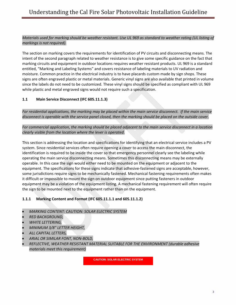
Materials used for marking should be weather resistant. Use UL 969 as standard to weather rating (UL listing of markings is not required). The section on marking covers the requirements for identification of PV circuits and disconnecting means. The intent of the second paragraph related to weather resistance is to give some specific guidance on the fact that marking circuits and equipment in outdoor locations requires weather resistant products. UL 969 is a standard entitled, “Marking and Labeling Systems” and covers resistance of labeling materials to UV radiation and moisture. Common practice in the electrical industry is to have placards custom made by sign shops. These signs are often engraved plastic or metal materials. Generic vinyl signs are also available that printed in volume since the labels do not need to be customized. These vinyl signs should be specified as compliant with UL 969 while plastic and metal engraved signs would not require such a specification.
1.1 Main Service Disconnect (IFC 605.11.1.3)
For residential applications, the marking may be placed within the main service disconnect. If the main service disconnect is operable with the service panel closed, then the marking should be placed on the outside cover. For commercial application, the marking should be placed adjacent to the main service disconnect in a location clearly visible from the location where the lever is operated. This section is addressing the location and specifications for identifying that an electrical service includes a PV system. Since residential services often require opening a cover to access the main disconnect, the identification is required to be inside the cover so that emergency personnel clearly see the labeling while operating the main service disconnecting means. Sometimes this disconnecting means may be externally operable. In this case the sign would either need to be mounted on the equipment or adjacent to the equipment. The specifications for these signs indicate that adhesive‐fastened signs are acceptable, however, some jurisdictions require signs to be mechanically fastened. Mechanical fastening requirements often makes it difficult or impossible to mount the sign on outdoor equipment since putting fasteners in outdoor equipment may be a violation of the equipment listing. A mechanical fastening requirement will often require the sign to be mounted next to the equipment rather than on the equipment.
1.1.1 Marking Content and Format (IFC 605.11.1.1 and 605.11.1.2)
• MARKING CONTENT: CAUTION: SOLAR ELECTRIC SYSTEM • RED BACKGROUND, • WHITE LETTERING, • MINIMUM 3/8” LETTER HEIGHT, • ALL CAPITAL LETTERS, • ARIAL OR SIMILAR FONT, NON‐BOLD, • REFLECTIVE, WEATHER RESISTANT MATERIAL SUITABLE FOR THE ENVIRONMENT (durable adhesive
materials meet this requirement) CAUTION: SOLAR ELECTRIC SYSTEM
Understanding the Cal Fire Solar Photovoltaic Installation Guideline
4
1.2 Marking for dc Conduit, Raceways, Enclosures, Cable Assemblies, and Junction Boxes (IFC 605.11.1 and 605.11.1.4)
Marking is required on all interior and exterior dc conduit, raceways, enclosures, cable assemblies, and junction boxes to alert the fire service to avoid cutting them. Marking should be placed on all interior and exterior dc conduit, raceways, enclosures, and cable assemblies, every 10 feet, at turns and above and/or below penetrations and all dc combiner and junction boxes. The dc side of the system requires identification according to the California guideline. Visual identification of different kinds of solar panels (electric and thermal) and equipment such as inverters, combiner boxes, disconnects, and wiring systems. With a basic understanding of these major components, along with the signs covered in this section, it should be clear to those fighting fires, or performing overhaul operations, that the equipment is present and a hazard exists during daylight hours. In commercial facilities, identification of the contents of piping systems, including electrical conduit, is common practice. These provisions are most suited to commercial applications. While there is no specific language exempting residential PV wiring systems from identifying these circuits, it is less necessary. Since residential wiring methods are dominated by non‐metallic cables, if the house has metal conduit installed, it is most likely either PV wiring or service entrance conductors—both of which should be avoided. Simply said, commercial buildings have numerous metal piping systems, necessitating identification for several reasons while metal piping is less common in residential structures, reducing the need for such identification. In either case, firefighters should avoid touching these conduit. If a fire is present in the structure, these metal raceways may have compromised conductors inside that could energize the metal shocking those who might touch them.
1.2.1 Marking Content and Format (IFC 605.11.1.1 and 605.11.1.2)
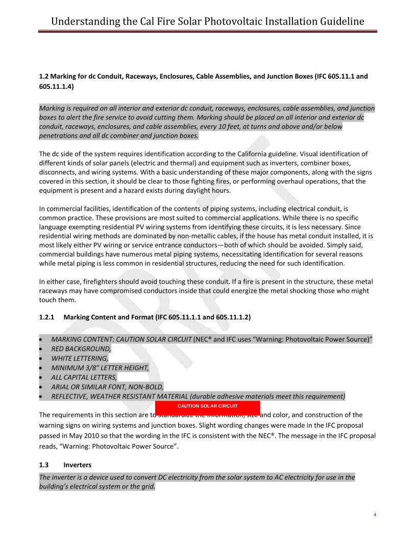
• MARKING CONTENT: CAUTION SOLAR CIRCUIT (NEC® and IFC uses “Warning: Photovoltaic Power Source)” • RED BACKGROUND, • WHITE LETTERING, • MINIMUM 3/8” LETTER HEIGHT, • ALL CAPITAL LETTERS, • ARIAL OR SIMILAR FONT, NON‐BOLD, • REFLECTIVE, WEATHER RESISTANT MATERIAL (durable adhesive materials meet this requirement) The requirements in this section are to standardize the information, size and color, and construction of the warning signs on wiring systems and junction boxes. Slight wording changes were made in the IFC proposal passed in May 2010 so that the wording in the IFC is consistent with the NEC®. The message in the IFC proposal reads, “Warning: Photovoltaic Power Source”.
1.3 Inverters
The inverter is a device used to convert DC electricity from the solar system to AC electricity for use in the building’s electrical system or the grid.
CAUTION SOLAR CIRCUIT
Understanding the Cal Fire Solar Photovoltaic Installation Guideline
5
No markings are required for the inverter. 2.0 ACCESS, PATHWAYS AND SMOKE VENTILATION (IFC 605.11.3) Section 2 of the guidelines only applies to fire departments that engage in vertical ventilation operations. While the majority of the fire service will engage in vertical ventilation operations, some departments are beginning to limit vertical ventilation based upon the type of construction of a structure, or the fire safety elements that the building includes. Some types of roof construction may not offer sufficient fire resistance to justify the risk of sending firefighters to the roof, while other buildings may have sufficient automatic vents making roof ventilation operations unnecessary. If manual roof ventilation is deemed unnecessary, the roof may only need access and egress for firefighting related to rooftop fires. Roof construction will also play a role in the decision process since non‐combustible roof decking such as concrete and metal may make ventilation or trenching operations impractical. While a few fire departments may engage in trenching operations on metal and concrete decked roofs, these departments are the exception rather than the rule. In general, exceptions to access pathways and smoke ventilation must be approved by the fire jurisdiction, so the specifics of construction and operations are intended to be handled through the design review process. Access and spacing requirements should be observed in order to:
• Ensure access to the roof • Provide pathways to specific areas of the roof • Provide for smoke ventilation opportunities area • Provide emergency egress from the roof
The introductory section of the access and smoke ventilation section outlines the purpose of this section. Since this section includes limiting locations for mounting PV modules, it is likely to be the focus of concern by those in the solar industry and in the fire service. Understanding the requirements in this section is critical to properly enforcing these rules and enabling flexibility to make adjustments to the rules when alternative means and methods can address the issues.
The first list of bullets outlines why the requirements for clear spaces are needed for firefighters. The first bullet, “Ensure access to the roof”, refers to the need for fire fighters to gain access to the roof usually with ladders or similar means. Once access to the roof is achieved, then getting to specific areas on the roof that need inspection or ventilation is needed, which is stated in the second bullet. Another reason for spacing areas on rooftops is to provide a location where the roof can be ventilated to help remove smoke from inside a structure (bullet 3). Lastly, pathways are also necessary to quickly get off of a roof as bullet four suggests. Typically, multiple pathways for egress are identified while fighting a fire so that if the fire cuts off one egress pathway, an alternative can be used. The alternative pathways may not need to be as wide or structurally sound as the primary locations for access and egress. Local jurisdictions may create exceptions to this requirement where access, pathway or ventilation requirements are reduced due to:
Understanding the Cal Fire Solar Photovoltaic Installation Guideline
6
• Proximity and type of adjacent exposures • Alternative access opportunities (as from adjoining roofs) • Ground level access to the roof area in question • Adequate ventilation opportunities beneath solar array (as with significantly elevated or
widely‐spaced arrays) • Adequate ventilation opportunities afforded by module set back from other rooftop equipment
(shading or structural constraints may leave significant areas open for ventilation near HVAC equipment, for example.)
• Automatic ventilation device. • New technology, methods, or other innovations that ensure adequate fire department access,
pathways and ventilation opportunities.
Designation of ridge, hip, and valley does not apply to roofs with 2‐in‐12 or less pitch. All roof dimensions measured to centerlines.
Roof access points should be defined as an area that does not place ladders over openings (i.e., windows or doors) and are located at strong points of building construction and in locations where it does not conflict with overhead obstructions such as tree limbs, wires, or signs.
The guidelines encourage local jurisdictions to have flexibility in the enforcement of these requirements due to a variety of site‐specific issues. The first three bullets describe examples of options that may allow fire departments to relax the setback options on a roof. PV arrays are often only mounted on one roof face (closest to south) so that other roof faces may be fully open to roof access and venting options.
The next two bullets describe examples of PV array placement that allows for sufficient venting options due to the array being tilted above the roof pitch sufficiently to access the roof below the array or gaps in the array to reduce the shading affects of rooftop equipment such as HVAC units or shrouds hiding this equipment. The last two bullet items describe currently available ventilation options (automatic roof vents) and potential new innovations that may allow easy removal of PV modules for roof ventilation access. All of these measure can and should be taken into account when evaluating optional means and methods to meet the intent of adequate roof access and ventilation opportunities.
2.1 Residential Systems—Single and Two‐Unit Residential Dwellings (IFC 605.11.3.2)
Plan review is required if a system is to be installed that will occupy more than 50% of the roof area of a residential building. Examples of these requirements appear at the end of this guideline. This statement is to delineate a relative system size where plan review is recommended. In order to achieve more than 50% of a residential roof are on a sloped roof typically means mounting PV modules on multiple roof faces. This complicates the installation and requires that the fire department review the plans to make sure that the PV system will still allow adequate access and ventilating opportunities. Systems that occupy less than 50% of a residence’s roof area are simpler and are likely to have sufficient access and ventilation opportunities. This recommendation is not specifically mentioned in the IFC language.
Understanding the Cal Fire Solar Photovoltaic Installation Guideline
7
2.1.1 Access (IFC 605.11.3 and 605.11.3.1)
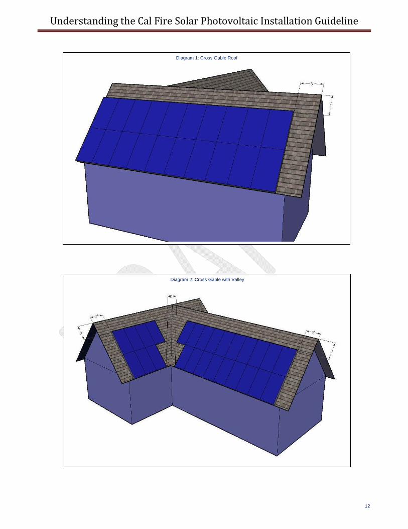
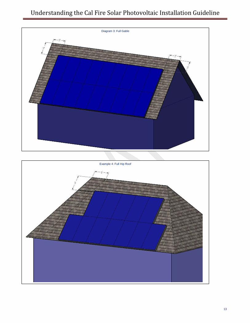
The 3’ access and ventilation requirements in 2.1.1. and 2.1.2 are among the most controversial items in the guideline for both the solar industry and fire fighters. The origin of the “3’ rule” was a result of lengthy deliberation and debate. Initially, the fire service requested 4’ setbacks while the solar industry preferred a 2’ setback. A 3’ setback was suggested that could reasonably address the access needs of the fire service while allowing more room for larger solar arrays to be installed. While the 3’ setback may appear to be a simple compromise between 2’ and 4’, the origin is technically based. An issue not commonly understood in the solar industry is that wind loading on rooftops limits the available roof area on many homes in high wind regions. The American Society of Civil Engineers (ASCE) publishes a standard ASCE‐7, entitled “Building Loads on Structures”, that is referenced by building codes in the U.S. This standard includes tables for wind pressures based upon location, wind exposure, and location on the roof. The outer 3’ corners of a residential sloped roof structure has wind pressures that are double that of 3’ in from the edge of the roof. Since PV modules are generally tested to withstand 30 PSF (pounds per square foot), areas of the country that have design wind speeds above 110 mph could experience wind pressures in excess of 30 PSF at roof corners. By staying away from the upper 3’ corners of a sloped roof, PV modules can be mounted safely within their structural design capabilities while providing firefighters the access they need to get to the ridge of the roof for ventilation operations. The assumption in this section is that each roof face must stand on its own without relying on access from other roof faces. The reason for this distinction is that, during roof operations, adjacent roof faces may not be available for access or ventilation holes. One reason for a roof face to be unavailable for ventilation operations is that a strong wind could be impinging on that roof face making ventilation holes counterproductive. Single ridge roofs, such as full gable construction, has structurally strong framed end walls that provide good access and egress for the firefighter to either end of the structure. Hip roofs often have a relatively small center ridge section while providing side ridges (hips) to get to the corners of the building. Since these hips are not as structurally strong as the single ridge gable ends, only a single 3’ pathway is required. This pathway is intended to be the primary access and egress for the roof. However, should this pathway be blocked or compromised during a fire since it is not as structurally strong as a gable end, firefighters would choose generally choose to make an emergency escape from the closest unaffected hip or slope to get to safety. (IFC 605.11.3.2.1)
a. Residential Buildings with hip roof layouts. Modules should be located in a manner that provides one (1) three‐foot (3’) wide clear access pathway from the eave to the ridge on each roof slope where modules are located. The access pathway should be located at a structurally strong location on the building (such as a bearing wall.)
Hip roofs only require one 3’ pathway because it is necessary for at least one 3’ pathway be available on any roof slope with a PV array. Although it is possible that a firefighter could walk on the opposing slope, there is a 3’ pathway on the PV slope in the event a firefighter is having to rapidly cross the hip slope to access the ladder that may be against the PV slope at the corner. This would limit the total distance and time the firefighter would need to traverse the roof to get to a ladder. (IFC 605.11.3.2.2)
b. Residential Buildings with a single ridge. Modules should be located in a manner that provides two (2) three‐foot (3’) wide access pathways from the eave to the ridge on each roof slope where modules are located.
Single ridge residences require two, 3’ wide pathways to provide alternate means of access and egress for firefighters during operations. As a related issue, these ridges can be long relative to the size of the structure so that there is a high likelihood that one pathway is inaccessible in a fire.
Understanding the Cal Fire Solar Photovoltaic Installation Guideline
8
(IFC 605.11.3.2.3)
c. Hips and Valleys: Modules should be located no closer than one and one half (1.5) feet to a hip or a valley if modules are to be placed on both sides of a hip or valley. If the modules are to be located on only one side of a hip or valley that is of equal length then the modules may be placed directly adjacent to the hip or valley.
Roof types covered in (a) and (b) are common simple roof constructions. However, many roofs cannot be described as simple hip or gable roofs but include a combination or ridges, valleys, and hips. Hips and valleys are treated differently from gable construction since the hips and valleys often do not have structural walls under them. This makes hips and valleys less substantial than other access and egress options and therefore a lower priority during firefighting operations. However, hips and valleys may become a path for emergency egress should a fire prevent the firefighter from accessing the preferred structural access and egress location.
2.1.2 Ventilation (IFC 605.11.3.2.4)
Modules should be located no higher than three feet (3) below the ridge. The purpose of the 3’ ridge setback for residential sloped roofs is twofold. First, it provides for access along the ridge for firefighters to move along the structurally stronger ridge. A minimum of 18” on either side of the ridge is generally used for a pathway so that firefighters can work their way along a roof ridge and step aside to allow another firefighter to pass without them having to get too far away from the stronger ridge section. Second, the 3’ space is intended to provide sufficient room for a standard 16 ft2 vent hole to be cut 2’ wide and 8’ long. This 2’ x 8’ hole is in lieu of the more common 4’x 4’ hole that is used for rafters or trusses on 24” centers. The 4’ x 4’ hole only requires a single hinging action with 24” rafter or truss construction, while a 2’ x 8’ hole requires additional cuts and at least two louvered sections. This method of venting is commonly referred to as “Dicing”. It allows for a scalable hole by just lengthening the top & bottom cuts and “dicing” in between, completing new louvered sections.
2.2 Commercial Buildings and Residential Housing Comprised of Three or More Units (IFC 605.11.3.3) This classification covers all habitable structures that are not one‐ and two‐ family residences. The intention to follow building code classifications since there are numerous distinctions in building code between single and two family residences and other building types. Exception: If a local fire department determines that the roof configuration is similar to residential (such as in the case of townhouses, condominiums, or single family attached buildings), the local fire department may make a determination to apply the residential access and ventilation requirements. Examples of these requirements appear at the end of this guideline.
2.2.1 Access (IFC 605.11.3.3.1)
There should be a minimum six (6) foot wide clear perimeter around the edges of the roof. Exception: If either axis of the building is 250 feet or less, there should be a minimum four feet (4’) wide clear perimeter around the edges of the roof.
Understanding the Cal Fire Solar Photovoltaic Installation Guideline
9
The access areas around the perimeter of a building are larger for commercial building than for single‐ and two‐family residences for a variety of reasons. One reason is that the gear and equipment required for some roof operations on larger commercial buildings may be significant. Another reason is that more firefighters are generally dispatched for larger buildings, needing extra space for firefighters to maneuver around one another—particularly in the vicinity of access ladders. The exception acknowledges the fact that smaller roofs will need less personnel and less clearance. For the solar industry, the perimeter area is often unusable due to two main reasons. First, shading from parapet walls on flat roofs can be significant. Generally, a setback distance of twice the parapet wall height is necessary to prevent excessive shading by the wall. A 3’ high parapet wall will require a 6’ setback to prevent shading. Second, higher wind speeds are associated with the perimeter of a roof making the edge of the roof unusable in many regions of the U.S. Lastly, the further the PV array is from the edge of a roof, the less likely construction workers will be exposed to edge of roof fall hazards.
2.2.2 Pathways (IFC 605.11.3.3.2)
Pathways should be established in the design of the solar installation. Pathways should meet the following requirements:
a. Should be over structural members b. Center line axis pathways should be provided in both axis of the roof. Center line axis pathways should
run on structural members or over the next closest structural member nearest to the center lines of the roof
c. Should be straight line not less than 4 feet clear to skylights and/or ventilation hatches d. Should be straight line not less than 4 feet clear to roof standpipes e. Should provide not less than 4 feet clear around roof access hatch with at least one not less than 4 feet
clear pathway to parapet or roof edge The pathway recommendations for commercial roofs are meant to place the walkways in locations most likely for firefighters would use during rooftop operations if no solar array were present. Generally, the firefighter will find a major structural member and follow that member across the roof when it is necessary to leave the roof edge. While following structural members is not always possible to do since the member may not be obvious, these provisions were intended to make those preferred paths available. Skylights, ventilation hatches, and standpipes are key ventilation and access locations that must have clear pathways from the edge of the roof, where the firefighter is free to move around the perimeter, to get to the ventilation location closest to the fire. Roof hatches may also be used for ventilation or building access depending on the source and type of the fire.
2.2.3 Ventilation (IFC 605.11.3.3.3)
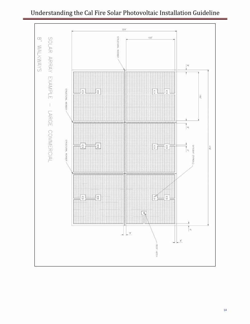
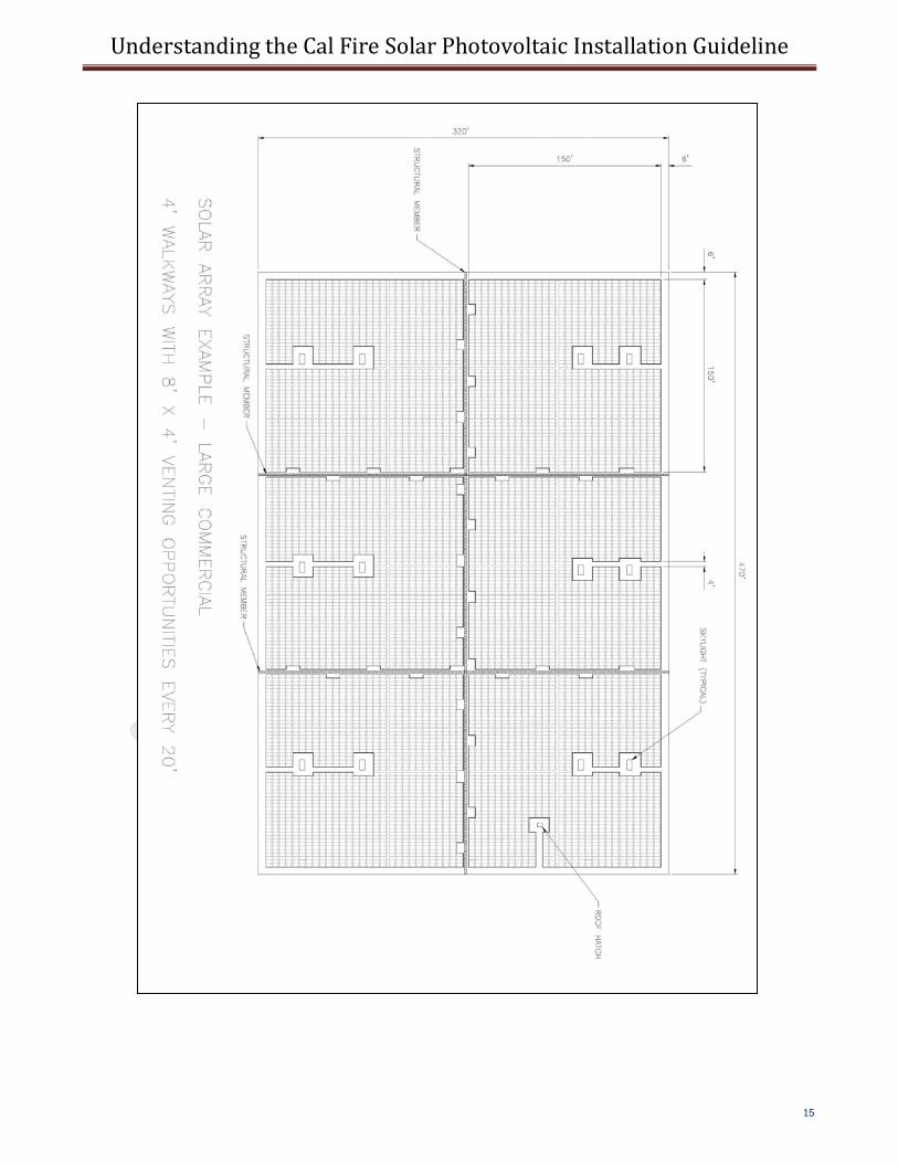
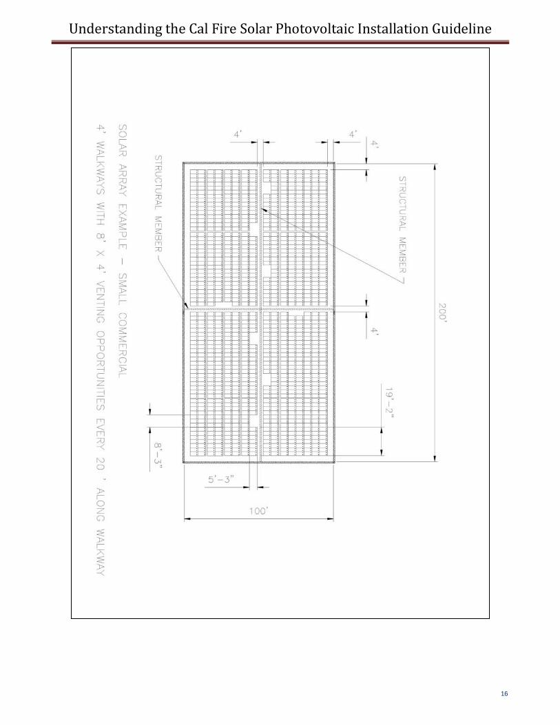
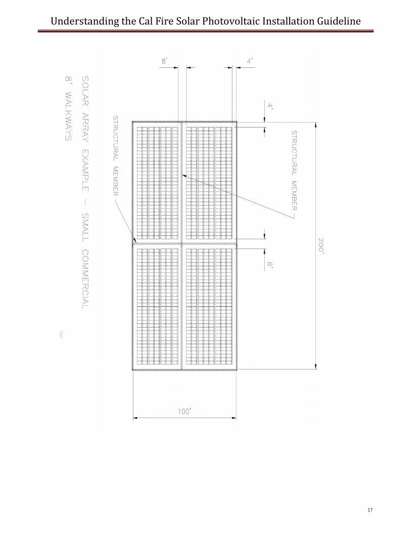
a. Arrays should be no greater than 150 by 150 feet in distance in either axis b. Ventilation options between array sections should be either:
1. A pathway 8 feet or greater in width 2. 4 feet or greater in width pathway and bordering on existing roof skylights or ventilation
hatches 3. 4 feet or greater in width pathway and bordering 4’ x 8’ “venting cutouts” every 20 feet on
alternating sides of the pathway The reason the size of the array is discussed in the ventilation section is to allow for ventilation opportunities no further apart than 150’. This assumes that a large building that could handle multiple 150’x150’ array blocks is fairly open so that smoke can travel to an available venting location. The more compartmentalized the space
Understanding the Cal Fire Solar Photovoltaic Installation Guideline
10
is below the roof, the more venting opportunities are preferred. Some buildings make ample use of skylights which can greatly help in providing venting opportunities for firefighters. Of course, these skylights and ventilation hatches need to be accessed with reasonable‐sized pathways. Maintenance personnel also need access to these locations to repair and maintain skylights and hatches. The third option is an attempt to allow for a 4’ wide walkway and yet take up less room than an 8’ pathway that would also be used for ventilation purposes. The alternating areas for ventilation are to provide venting options on either side of a structural member in case that structural member is over a partition wall. While this option helps meet the needs of the fire service, alternating sides of the pathway would not be a preferred method for the effective layout of a PV array so it is less likely to be used by PV system designers.
3.0 LOCATION OF DC CONDUCTORS (IFC 605.11.2)
Conduit, wiring systems, and raceways for photovoltaic circuits should be located as close as possible to the ridge or hip or valley and from the hip or valley as directly as possible to an outside wall to reduce trip hazards and maximize ventilation opportunities. Conduit runs between sub arrays and to DC combiner boxes should use design guidelines that minimize total amount of conduit on the roof by taking the shortest path from the array to the DC combiner box. The DC combiner boxes are to be located such that conduit runs are minimized in the pathways between arrays. To limit the hazard of cutting live conduit in venting operations, DC wiring should be run in metallic conduit or raceways when located within enclosed spaces in a building and should be run, to the maximum extent possible, along the bottom of load‐bearing members. Since the development of these guidelines in early 2008, several additions have been made to the 2011 National Electrical Code (NEC®) to address concern of firefighters in the routing of conductors. In the majority of residential rooftop systems, conduit is run exterior to the structure. Conduit runs generally proceed from the edge of the array closest to the location of the inverter, and the shortest possible path is taken to get to the inverter. Ridges, hips and valleys may be used to run conduit as recommended in this section. If conduit is run inside the structure, this is typically done in attic spaces so the last paragraph makes the statement to run the conduit along the bottom of load‐bearing members to the extent possible. The purpose behind this recommendation is that since firefighters are not going to cut through load‐bearing members, this would be a safer location to route conduit. However, other options may be as good or better in reducing the likelihood of conduit damage from firefighter operations. A series of requirements adopted by the 2011 NEC more specifically clarify the acceptable options. These sections are shown here for reference. 690.4 (E) (E) Circuit Routing. Photovoltaic source and PV output conductors, in and out of conduit, and inside of a building or structure, shall be routed along building structural members such as beams, rafters, trusses, and columns where the location of those structural members can be determined by observation. Where circuits are imbedded in built‐up, laminate, or membrane roofing materials in roof areas not covered by PV modules and associated equipment, the location of circuits shall be clearly marked. 690.31(E) (New) Wiring methods shall not be installed within 25 cm (10 in.) of the roof decking or sheathing except where directly below the roof surface covered by PV modules and associated equipment. Circuits shall be run vertically from the roof penetration point to supports a minimum of 25 cm (10 in.) below the roof decking.
Understanding the Cal Fire Solar Photovoltaic Installation Guideline
11
Informational Note: The 25 cm (10 in.) requirement is to prevent accidental damage from saws used by firefighters for roof ventilation during a structure fire.
Where flexible metal conduit (FMC) or metal clad cable (MC) smaller than metric designator 21 (trade size 3⁄4) containing PV power circuit conductors is installed across ceilings or floor joists, the raceway or cable shall be protected by substantial guard strips that are at least as high as the raceway or cable. Where run exposed, other than within 1.8 m (6 ft) of their connection to equipment, these wiring methods shall closely follow the building surface or be protected from physical damage by an approved means:
4.0 NON‐HABITABLE BUILDINGS (IFC 605.11.4)
This guideline does not apply to non‐habitable structures. Examples of non‐habitable structures include, but are not limited to, parking shade structures, solar trellises, etc.
5.0 GROUND MOUNTED PHOTOVOLTIAC ARRAYS (IFC 605.11.4)
Setback requirements do not apply to ground‐mounted, free standing photovoltaic arrays. A clear brush area of 10’ is required for ground mounted photovoltaic arrays.
Clear brush areas are required around ground mounted systems to reduce the safety hazard of fuel from brush that could start a fire that would propagate beyond the limits of the PV array.
Examples of Compliant PV Array Layout for Different Rooftops (shown on following pages) Example 1 – Cross Gable Roof Example 2 – Cross Gable With Valley Example 3 – Full Gable Example 4 – Full Hip Roof Example 5 – Large Commercial 8’ Walkways Example 6 – Large Commercial 4’ Walkways Example 7 – Small Commercial 4’ Walkways Example 8 – Small Commercial 8’ Walkways
Understanding the Cal Fire Solar Photovoltaic Installation Guideline
12
Diagram 1: Cross Gable Roof
Diagram 2: Cross Gable with Valley
Understanding the Cal Fire Solar Photovoltaic Installation Guideline
13
Diagram 3: Full Gable
Example 4: Full Hip Roof
Understanding the Cal Fire Solar Photovoltaic Installation Guideline
14
Understanding the Cal Fire Solar Photovoltaic Installation Guideline
15
Understanding the Cal Fire Solar Photovoltaic Installation Guideline
16
Understanding the Cal Fire Solar Photovoltaic Installation Guideline
17
Understanding the Cal Fire Solar Photovoltaic Installation Guideline
18
INFORMATION INTENTIONALLY OMITTED FROM THE GUIDELINES
PV ARRAY DC DISCONNECTS TO PROTECT FIREFIGHTERS
As members of the Fire Service have been tasked with developing installation guidelines for PV systems in the past decade, one of the most common requirements that are drafted relates to disconnects on rooftops. The assumption is that adding disconnects at the source of power, the PV array, will effectively eliminate that source from the building. The history of service disconnects for fire operations is to protect fire fighters from energized conductors. One of the first activities of a team of fire fighters is to control the energy utilities to a structure (typically utility electrical and gas). The addition of a PV system on the roof of the structure poses a unique challenge to fire fighter operations.
Unfortunately, given the design and layout of a rooftop PV system, opening a disconnect may not de‐energize any of the circuits associated with the switch. The reasons for this will be covered later in this document. If the circuits are not de‐energized, and a firefighter believes that it is safe to move a raceway associated with that switch, it is possible that the firefighter could be severely shocked or electrocuted. For this reason, the California Fire Service’s, Draft Solar Photovoltaic Installation Guideline, dated April of 2008 does not include any language related to rooftop PV array switches. The guidelines also do not state why such a requirement was omitted. This has caused various jurisdictional authorities and fire enforcement representatives to believe that the omission was accidental and proceed to introduce an additional requirement.
PROPOSED LANGUAGE FOR IFC F30
611.6 Power disconnects. A power disconnect shall be located within 3 feet of the photovoltaic array to provide for de‐energizing the DC circuit(s) from the array to the inverter. The disconnect shall be labeled with reflective lettering.
THE PROBLEM
As stated in the introduction, opening a rooftop dc disconnect in a PV system does not de‐energize the conductors on either side of the switch. Because of this concern, the National Electrical Code (NEC), published by the National Fire Protection Association as standard NFPA 70, requires a warning sign on these types of switches. This sign must read substantially
WARNING. ELECTRIC SHOCK HAZARD.
DO NOT TOUCH TERMINALS. TERMINALS ON BOTH THE LINE AND LOAD SIDES MAY BE ENERGIZED IN THE OPEN POSITION.
Understanding the Cal Fire Solar Photovoltaic Installation Guideline
19
This warning is primarily for electricians performing work on the equipment as a reminder that normal electrical conventions do not hold for this equipment. Normally, a safety disconnect has energized conductors to the line side of the switch, but the load side of the switch is always de‐energized when the switch is open. This is due to the fact that no other source of power typically exists on the load side of a switch. With PV systems, this assumption is wrong in almost every case, thus the requirement for a warning sign.
To understand why the load side of a dc switch in a PV array is typically energized, we must look at how PV systems work, and the common equipment that is used. The majority of rooftop PV systems are connected directly to an electrical converter, called an inverter, that takes the dc power from the PV array, turns it into ac power compatible with the utility system, and then supplies that power to existing distribution equipment in the building. On the ac side, if the utility power is shut down for any reason, the ac output of the PV system inverter instantly shuts down to prevent a hazardous condition on the ac wiring in the building or local utility. If the ac side is shut down, the dc power from the array instantly stops flowing. The dc current stops, but the dc voltage remains—the PV array sits in an open‐circuit condition awaiting the return of utility power.
This open‐circuit condition, while not flowing power, is none‐the‐less hazardous to anyone coming in contact with the circuits. That is the fundamental reason the fire service logically wants to shut the voltage off in that circuit. In small, residential rooftop PV systems, all the circuits from the roof are typically run into a single raceway so it seems logical to install a dc disconnect to de‐energize this conduit. Although it is possible to interrupt the circuit from the roof to the inverter, the voltage on the load side of the switch is coming from the inverter. This voltage comes from an additional source in the inverter—that source is the input capacitors for the array.
All PV inverters without battery systems include large input capacitors. The purpose of these input capacitors is to store “half‐wave” power from the PV array so that the inverter can produce ac power, which fluctuates at 60 cycles, and keep the power from the PV array at a constant dc voltage (INSERT DIAGRAM SHOWING DC AND AC POWER). These capacitors have “bleed resistors” attached to them to gradually deplete the charge to zero volts when the voltage is removed from them. This bleed‐down process takes 5 to 15 minutes and is intended to make the equipment safe for servicing. This 5 to 15 minute time period is fine for maintenance work, but far too long for fire operations. A firefighter, thinking this circuit is de‐energized, could easily be shocked by these large capacitors. While the shock on a small PV system is unlikely to be fatal, the involuntary muscle reaction to the shock could easily cause the fire fighter to lose balance and fall off the roof resulting in serious injury or fatality.
On larger commercial PV systems, there can be dozens of electrical distribution boxes all electrically combined at a large inverter at ground level. Although the 2011 NEC will require dc disconnects for each rooftop combiner box, turning off any one of these disconnects, or all the disconnects, may not de‐energize any of the circuits or conduit. For the same reason small systems are not de‐energized, large inverters have massive capacitor banks that are capable of delivering a severe burn or even electrocution. These capacitor banks have bleed resistors, but the same 5 to 15 minute waiting period exists for big inverters just like small inverters. The capacitors will only start to discharge after all the rooftop disconnects are opened.
Understanding the Cal Fire Solar Photovoltaic Installation Guideline
20
IMPACT ON FIRE OPERATIONS
The typical protection that a disconnecting means provides with utility ac services does not exist with dc disconnects in a PV system. The conventional ac frame of reference used by an electrician or a firefighter while doing their job is dangerous and potentially fatal. Thus the code requirement for warning signs on all these disconnects. For example, if 15 disconnects exist on the roof, one at the location of each subarray combiner box, only one of the 15 need to stay on in order for the entire array wiring system to stay fully energized and lethal. In the smoke and confusion during a fire, it is too likely that one or more of these disconnects will not be identifiable or accessible because fire is blocking access. Firefighters in daytime operations need to work from the assumption that the equipment is energized and potentially dangerous.
The 2011 NEC has established several new requirements for PV systems in routing of wiring systems, marking, arc‐fault detection systems, and disconnects for combiner boxes. These improvements in safety will not solve all current hazards, but they will reduce the hazard to firefighters and maintenance personnel.
Basic education on the hazards of PV systems is the key to effective fire fighting operations. While disconnects on combiner boxes will help isolate circuits during overhaul operations, they should not be the focus during fire suppression operations. Simply staying clear of PV modules and the associated raceways is the only way to guaranty the safety of the fire fighter. Requiring disconnects, from a fire safety point of view, should be carefully considered in light of the misunderstandings and potential injury these misunderstandings will ultimately result in.
TECHNOLOGY ADVANCES THAT MAKE PV SYSTEMS SAFER
While current PV system design does not favor the use of dc disconnects to provide protection for firefighters, several new technologies show promise of addressing some or all of the major electrical concerns of the firefighter. These new technologies place communications and control features directly into each module, allowing individual modules to shut down instantly if necessary. These module‐level electronics, sometimes called Module‐Level Control or Smart Modules, could easily communicate with the inverter and shut each module off in the event of a utility outage or the opening of the main ac service disconnect. By controlling the voltage at the module level, the electrical hazards of the PV array are removed allowing the firefighter to concentrate on their main goal of fire suppression rather than energy control for the PV system.
Understanding the Cal Fire Solar Photovoltaic Installation Guideline
21
New regulation under development for the IFC and UFC There are two primary fire codes used in the U.S. today. The first is the International Fire Code (IFC) published every 3 years by the International Code Council (ICC). The second is the Uniform Fire Code (UFC) published by the National Fire Protection Association (NFPA). The UFC is often referred by the code designation of NFPA 1. Both draft documents for the 2012 code cycle include language related to solar photovoltaic system regulation that is based upon the California guideline. One significant difference between the California document and these fire regulations is the emphasis of the language. Since the California document is a recommended practice, and not a requirement, words like “must” and “shall” cannot be used. However, since the IFC and UFC are standards written as requirements, the word “shall” is used in place of “should.” The IFC F30 Code compared to the California Guideline This section will outline the significant differences between the IFC F30 requirements and the California Guideline. As of the initial draft of this document, it was unclear what language would be adopted by the UFC so that comparison will wait for a future version of this report. Setting the two documents side‐by‐side it becomes clear that the IFC regulation is largely based upon the California document with the increased emphasis of code requirements. However, several important differences do exist. Rather than cover all the similarities, only the significant differences will be addressed in this section. The reasoning behind issues such as access, pathways, and ventilation have not been changed, but the reasons for the different language will be discussed in the context of rest of this explanation document. To summarize the differences up front, the following list is provided.
1. All instances of “should” were removed and changed to “shall” as appropriate to make the statements code requirements rather than recommendations.
2. The recommendation to have access pathways on top of structural members of building is amended to require only that the roof be capable of handling the live load of a firefighter.
3. The exception for the option for fire departments to amend the 3’ rule for residences is prominently featured at the beginning of the section on access, pathways, and smoke ventilation.
4. The National Electrical Code is referenced for additional requirements for marking, labeling, and routing of wiring methods.
5. Ladder access is specified so that the locations are not in front of windows or doors, and the access points do not conflict with obstructions such as tree limbs, wires, or signs.
New Language for the 2012 IFC: 605.11 Solar Photovoltaic Power Systems. Solar photovoltaic power systems shall be installed in accordance with this code, the International Building Code and NFPA 70.
Understanding the Cal Fire Solar Photovoltaic Installation Guideline
22
Exception: Detached Group U non‐habitable structures such as parking shade structures, carports, solar trellises, and similar type structures are not subject to the requirements of this section.
605.11.1 Marking Marking is required on all interior and exterior dc conduit, enclosures, raceways, cable assemblies, junction boxes, combiner boxes, and disconnects.
605.11.1.1 Materials. The materials used for marking shall be reflective, weather resistant and suitable for the environment. Marking as required in sections 605.11.1.2 through 605.11.1.4 shall have all letters capitalized with a minimum height of 3/8 inch (9.5 mm) white on red background.
605.11.1.2 Marking content. The marking shall contain the words WARNING: PHOTOVOLTAIC POWER SOURCE.
605.11.1.3 Main service disconnect The marking shall be placed adjacent to the main service disconnect in a location clearly visible from the location where the disconnect is operated.
605.11.1.4 Location of Marking. Marking shall be placed on all interior and exterior dc conduit, raceways, enclosures and cable assemblies every 10 feet (3048 mm) within 1 foot (305 mm) of all turns or bends and within 1 foot (305 mm) above and below all penetrations of roof/ceiling assemblies and all walls and /or barriers.
605.11.2 Locations of DC conductors. Conduit, wiring systems, and raceways for photovoltaic circuits shall be located as close as possible to the ridge or hip or valley and from the hip or valley as directly as possible to an outside wall to reduce trip hazards and maximize ventilation opportunities. Conduit runs between sub arrays and to DC combiner boxes shall be installed in a manner that minimizes total amount of conduit on the roof by taking the shortest path from the array to the DC combiner box. The DC combiner boxes shall be located such that conduit runs are minimized in the pathways between arrays. DC wiring shall be installed in metallic conduit or raceways when located within enclosed spaces in a building. Conduit shall run along the bottom of load bearing members.
605.11.3 Access and pathways. Roof access, pathways, and spacing requirements shall be provided in order to ensure access to the roof; provide pathways to specific areas of the roof; provide for smoke ventilation operations; and to provide emergency egress from the roof.
Exceptions:
1. Requirements relating to ridge, hip, and valleys do not apply to roofs slopes of two units vertical in twelve units horizontal (2:12) or less.
2. Residential structures shall be designed so that each array is no greater than 150 feet (45 720 mm) by 150 feet (45 720 mm) in either axis.
3. The fire chief may allow panels/modules to be located up to the ridge when an alternative ventilation method acceptable to the fire chief has been provided or where the fire chief has determined vertical ventilation techniques will not be employed.
Understanding the Cal Fire Solar Photovoltaic Installation Guideline
23
605.11.3.1 Roof access points. Roof access points shall be defined as an area that does not place ground ladders over openings such as windows or doors, and are located at strong points of building construction in locations where the access point does not conflict with overhead obstructions such as tree limbs, wires, or signs.
605.11.3.2 Residential systems for one‐ and two‐family residential dwellings. Access shall be provided in accordance with Sections 605.11.3.2.1 through 605.11.3.2.4
605.11.3.2.1 Residential buildings with hip roof layouts. Panels/modules shall be located in a manner that provides a 3 foot (914 mm) wide clear access pathway from the eave to the ridge on each roof slope where panels/modules are located. The access pathway shall be located at a structurally strong location on the building capable of supporting the live load of fire fighters accessing the roof.
605.11.3.2.2 Residential buildings with a single ridge. Panels/modules shall be located in a manner that provides two 3 foot (914 mm) wide access pathways from the eave to the ridge on each roof slope where panels/modules are located.
605.11.3.2.3 Hips and Valleys: Panels/modules shall be located no closer than 18 inches (457 mm) to a hip or a valley if panels/modules are to be placed on both sides of a hip or valley. If the panels are to be located on only one side of a hip or valley that is of equal length then the panels shall be permitted to be placed directly adjacent to the hip or valley.
605.11.3.2.4 Smoke Ventilation. Panels/modules shall be located no higher than 3 feet (914 mm) below the ridge in order to allow for fire department smoke ventilation operations.
605.11.3.3 All other occupancies. Access shall be provided in accordance with Sections 605.11.3.3.1 through 605.11.3.3.3.
Exception: Where it is determined by the fire code official that the roof configuration is similar to a one‐ or two‐family dwelling, the fire code official may approve the residential access and ventilation requirements provided in 605.11.3.2.1 through 605.11.3.2.4.
605.11.3.3.1 Access. There shall be a minimum 6 foot (1829 mm) wide clear perimeter around the edges of the roof.
Exception: If either axis of the building is 250 feet (76 200 mm) or less, there shall be a minimum 4 foot (1290 mm) wide clear perimeter around the edges of the roof.
605.11.3.3.2 Pathways. The solar installation shall be designed to provide designated pathways. The pathways shall meet the following requirements:
1. The pathway shall be over areas capable of supporting the live load of fire fighters accessing the roof
2. The center line axis pathways shall be provided in both axis of the roof. Center line axis pathways shall run where the roof structure is capable of supporting the live load of firefighters accessing the roof.
3. Shall be straight line not less than 4 feet (1290 mm) clear to skylights and/or ventilation hatches
Understanding the Cal Fire Solar Photovoltaic Installation Guideline
24
4. Shall be straight line not less than 4 feet (1290 mm) clear to roof standpipes
5. Shall provide not less than 4 feet (1290 mm) clear around roof access hatch with at least one not less than 4 feet (1290 mm) clear pathway to parapet or roof edge
605.11.3.3.3 Smoke Ventilation. The solar installation shall be designed to meet the following requirements:
1. Arrays shall be no greater than 150 feet (45 720 mm) by 150 feet (45 720 mm) in distance in either axis in order to create opportunities for smoke ventilation operations.
2. Smoke ventilation options between array sections shall be one of the following:
2.1. A pathway 8 feet (2438 mm) or greater in width;
2.2. A 4 feet (1290 mm) or greater in width pathway and bordering roof skylights or smoke and heat vents;
2.3. A 4 feet (1290 mm) or greater in width pathway and bordering 4 foot (1290 mm) x 8 foot (2438 mm) “venting cutouts” every 20 feet (6096 mm) on alternating sides of the pathway
605.11.4 Ground mounted photovoltaic arrays. Ground mounted photovoltaic arrays shall comply with Sections 605.11 through 605.11.2 and this section. Setback requirements do not apply to ground‐mounted, free standing photovoltaic arrays. A clear brush area of 10 feet (3048 mm) is required for ground mounted photovoltaic arrays.