Embed Size (px)
Citation preview
NREL is a national laboratory of the U.S. Department of Energy, Office of Energy Efficiency & Renewable Energy, operated by the Alliance for Sustainable Energy, LLC.
Contract No. DE‐AC36‐08GO28308
United States Country Report
IEA Bioenergy, Task 33
R. Bain Prepared under Task No. WW3E.1000
August 20, 2011
National Renewable Energy Laboratory 1617 Cole Boulevard Golden, Colorado 80401 303‐275‐3000 • www.nrel.gov
Contract No. DE‐AC36‐08GO28308
United States Country Report
IEA Bioenergy, Task 33
R. Bain, Prepared under Task No. WW3E.1000
August 2011
iii IEA Bioenergy, Task 33, United States Country Report
Contract No. DE‐AC36‐08GO28308
NOTICE
This report was prepared as an account of work sponsored by an agency of the United States government. Neither the United States government nor any agency thereof, nor any of their employees, makes any warranty, express or implied, or assumes any legal liability or responsibility for the accuracy, completeness, or usefulness of any information, apparatus, product, or process disclosed, or represents that its use would not infringe privately owned rights. Reference herein to any specific commercial product, process, or service by trade name, trademark, manufacturer, or otherwise does not necessarily constitute or imply its endorsement, recommendation, or favoring by the United States government or any agency thereof. The views and opinions of authors expressed herein do not necessarily state or reflect those of the United States government or any agency thereof.
Cover Photos: (left to right) PIX 16416, PIX 17423, PIX 16560, PIX 17613, PIX 17436, PIX 17721
Printed on paper containing at least 50% wastepaper, including 10% post consumer waste
IEA Bioenergy, Task 33, United States Country Report
Draft Page 4
Table of Contents
STATUS OF BIOMASS ENERGY SYSTEMS IN THE UNITED STATES ............................................................. 5
RESOURCE AVAILABILITY ESTIMATES ..................................................................................................... 11
BIOMASS GASIFICATION OVERVIEW ...................................................................................................... 17
USDOE INTEGRATED BIREFINERY PROJECTS .......................................................................................... 24
U.S. GASIFIER DEVELOPERS .................................................................................................................... 33
STATUS OF SELECTED GASIFIERS WITH PROJECTS IN U.S. ...................................................................... 38
List of Figures
Figure 1: U.S. 2009 Primary Energy Consumption ........................................................................................ 5 Figure 2: U.S. 2009 Electricity Generation .................................................................................................... 6 Figure 3: Historical Growth of the U.S. Biopower Industry .......................................................................... 7 Figure 4: Map of biopower plant locations in United States ........................................................................ 9 Figure 5: Ethanol Production in the United States ....................................................................................... 9 Figure 6: Biodiesel Production in the United States, .................................................................................. 10 Figure 7: Distribution of urban wood residues in United States ................................................................ 12 Figure 8: Distribution of primary wood mill residues in United States ...................................................... 12 Figure 9. Distribution of forest residues in United States .......................................................................... 13 Figure 10. Distribution of crop residues in United States ........................................................................... 13 Figure 11: Municipal solid waste generation and use in United States ...................................................... 14 Figure 12: USA Biomass Potential ............................................................................................................... 15 Figure 13: Cost curves for potential delivered biomass, 2005–2025 ......................................................... 16 Figure 14: Biomass Gasifier Types .............................................................................................................. 21 Figure 15: USDOE Gasification IBR Projects ................................................................................................ 24
List of Tables
Table 1: Biomass Capacity and Generation, EIA AEO 2006–2010a .............................................................. 8 Table 2. Representative Biomass & Fossil Fuel Compositions .................................................................... 17 Table 3: Representative Gas Composition for Fluid Bed and Circulating Fluid Bed Gasifiers .................... 23 Table 4: Estimated BCL gas compositions ................................................................................................... 40 Table 5: Comparison of Pilot and Demonstration Gas Composition .......................................................... 40 Table 6 IGT Pilot conditions, Yields, Gas Composition ................................................................................ 49 Table 7: Pilot Syngas Composition (Piccot et al 2011) ................................................................................ 53 Table 8: InEnTec PEM synthesis gas compositions .................................................................................... 65
IEA Bioenergy, Task 33, United States Country Report
Draft Page 5
STATUS OF BIOMASS ENERGY SYSTEMS IN THE UNITED STATES
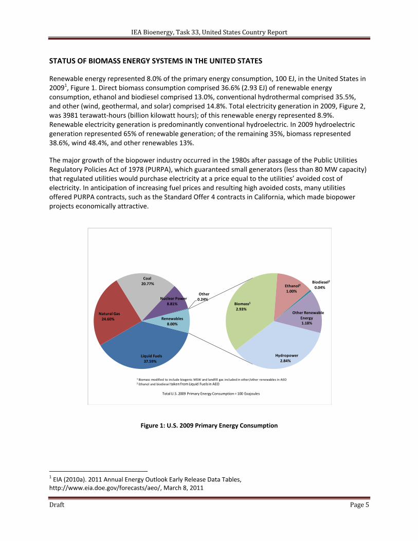
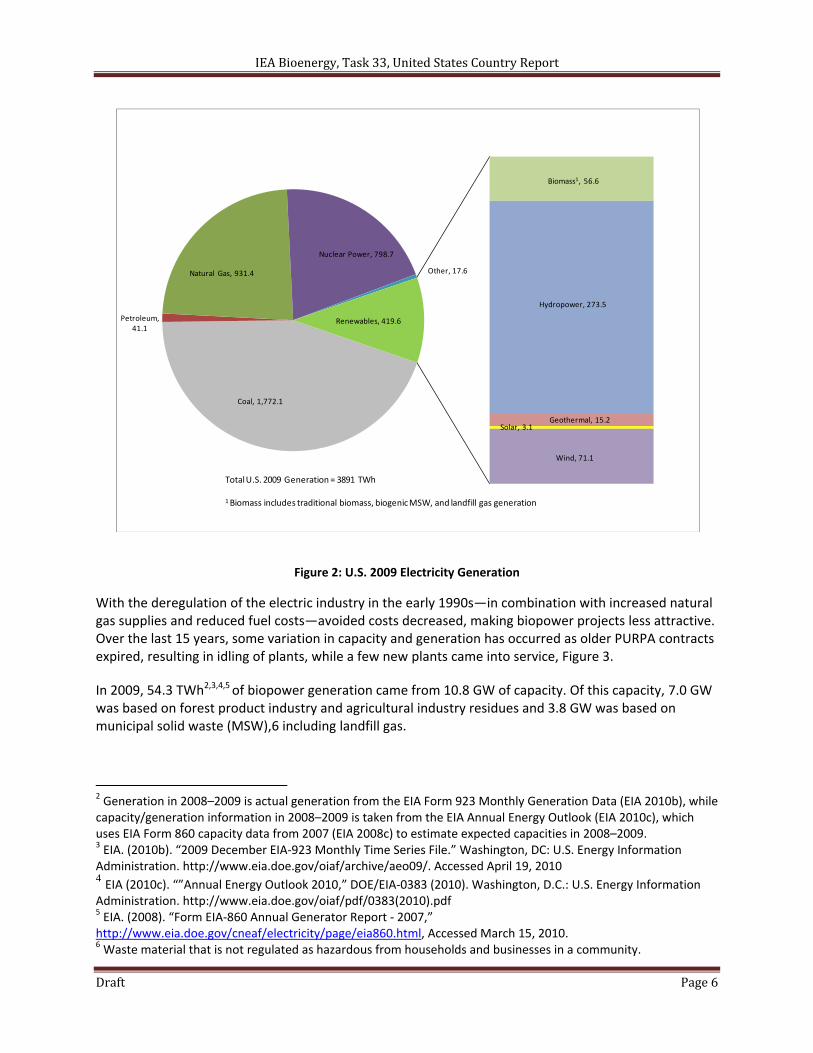
Renewable energy represented 8.0% of the primary energy consumption, 100 EJ, in the United States in 20091, Figure 1. Direct biomass consumption comprised 36.6% (2.93 EJ) of renewable energy consumption, ethanol and biodiesel comprised 13.0%, conventional hydrothermal comprised 35.5%, and other (wind, geothermal, and solar) comprised 14.8%. Total electricity generation in 2009, Figure 2, was 3981 terawatt‐hours (billion kilowatt hours); of this renewable energy represented 8.9%. Renewable electricity generation is predominantly conventional hydroelectric. In 2009 hydroelectric generation represented 65% of renewable generation; of the remaining 35%, biomass represented 38.6%, wind 48.4%, and other renewables 13%.
The major growth of the biopower industry occurred in the 1980s after passage of the Public Utilities Regulatory Policies Act of 1978 (PURPA), which guaranteed small generators (less than 80 MW capacity) that regulated utilities would purchase electricity at a price equal to the utilities’ avoided cost of electricity. In anticipation of increasing fuel prices and resulting high avoided costs, many utilities offered PURPA contracts, such as the Standard Offer 4 contracts in California, which made biopower projects economically attractive.
Figure 1: U.S. 2009 Primary Energy Consumption
1 EIA (2010a). 2011 Annual Energy Outlook Early Release Data Tables, http://www.eia.doe.gov/forecasts/aeo/, March 8, 2011
Liquid Fuels
37.59%
Natural Gas
24.60%
Coal 20.77%
Nuclear Power
8.81%
Other0.24%
Hydropower
2.84%
Biomass1
2.93%
Ethanol2
1.00%
Biodiesel2
0.04%
Other Renewable Energy1.18%
Renewables
8.00%
1 Biomass modified to include biogenic MSW and landfill gas included in other/other renewables in AEO2 Ethanol and biodiesel taken from Liquid Fuels in AEO
Total U.S. 2009 Primary Energy Consumption = 100 Exajoules
IEA Bioenergy, Task 33, United States Country Report
Draft Page 6
Figure 2: U.S. 2009 Electricity Generation
With the deregulation of the electric industry in the early 1990s—in combination with increased natural gas supplies and reduced fuel costs—avoided costs decreased, making biopower projects less attractive. Over the last 15 years, some variation in capacity and generation has occurred as older PURPA contracts expired, resulting in idling of plants, while a few new plants came into service, Figure 3.
In 2009, 54.3 TWh2,3,4,5 of biopower generation came from 10.8 GW of capacity. Of this capacity, 7.0 GW was based on forest product industry and agricultural industry residues and 3.8 GW was based on municipal solid waste (MSW),6 including landfill gas.
2 Generation in 2008–2009 is actual generation from the EIA Form 923 Monthly Generation Data (EIA 2010b), while capacity/generation information in 2008–2009 is taken from the EIA Annual Energy Outlook (EIA 2010c), which uses EIA Form 860 capacity data from 2007 (EIA 2008c) to estimate expected capacities in 2008–2009. 3 EIA. (2010b). “2009 December EIA‐923 Monthly Time Series File.” Washington, DC: U.S. Energy Information Administration. http://www.eia.doe.gov/oiaf/archive/aeo09/. Accessed April 19, 2010 4 EIA (2010c). “”Annual Energy Outlook 2010,” DOE/EIA‐0383 (2010). Washington, D.C.: U.S. Energy Information Administration. http://www.eia.doe.gov/oiaf/pdf/0383(2010).pdf 5 EIA. (2008). “Form EIA‐860 Annual Generator Report ‐ 2007,” http://www.eia.doe.gov/cneaf/electricity/page/eia860.html, Accessed March 15, 2010. 6 Waste material that is not regulated as hazardous from households and businesses in a community.
Coal, 1,772.1
Petroleum, 41.1
Natural Gas, 931.4
Nuclear Power, 798.7
Other, 17.6
Biomass1, 56.6
Hydropower, 273.5
Geothermal, 15.2Solar, 3.1
Wind, 71.1
Renewables, 419.6
Total U.S. 2009 Generation = 3891 TWh
1Biomass includes traditional biomass, biogenic MSW, and landfill gas generation
IEA Bioenergy, Task 33, United States Country Report
Draft Page 7
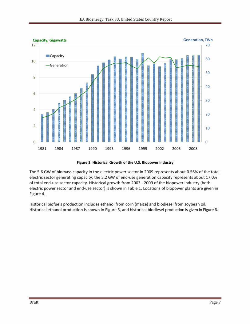
Figure 3: Historical Growth of the U.S. Biopower Industry
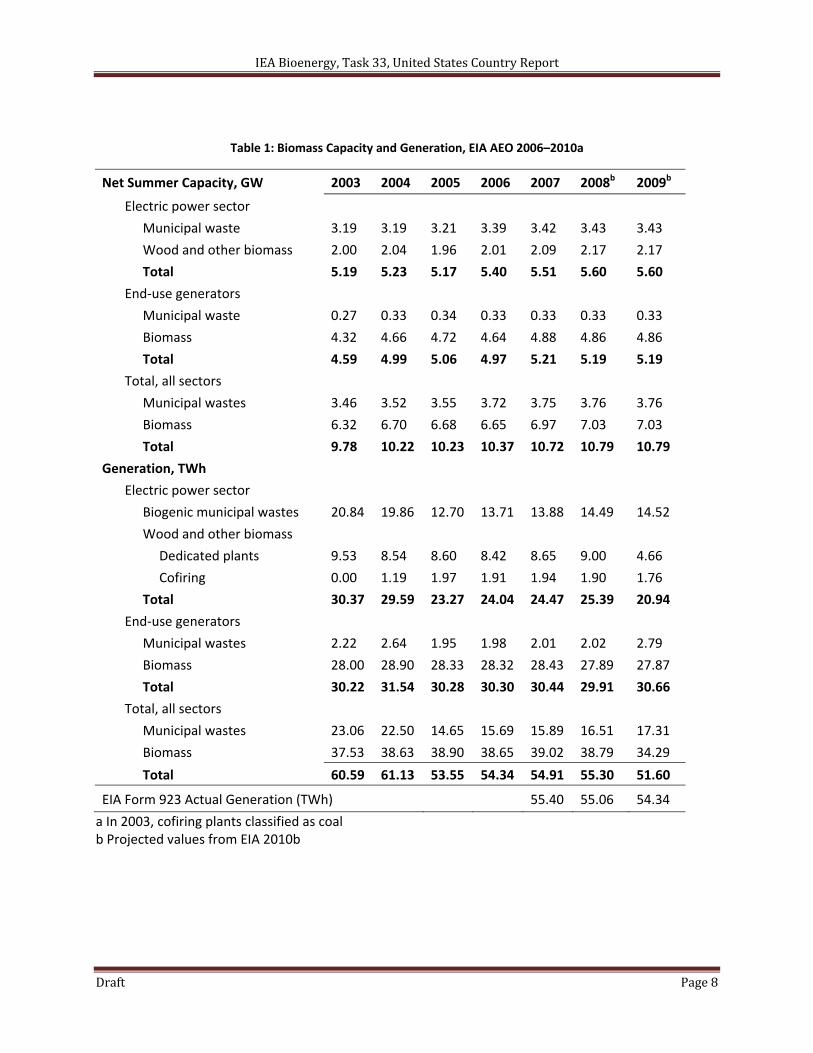
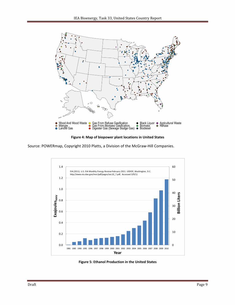
The 5.6 GW of biomass capacity in the electric power sector in 2009 represents about 0.56% of the total electric sector generating capacity; the 5.2 GW of end‐use generation capacity represents about 17.0% of total end‐use sector capacity. Historical growth from 2003 ‐ 2009 of the biopower industry (both electric power sector and end‐use sector) is shown in Table 1. Locations of biopower plants are given in Figure 4.
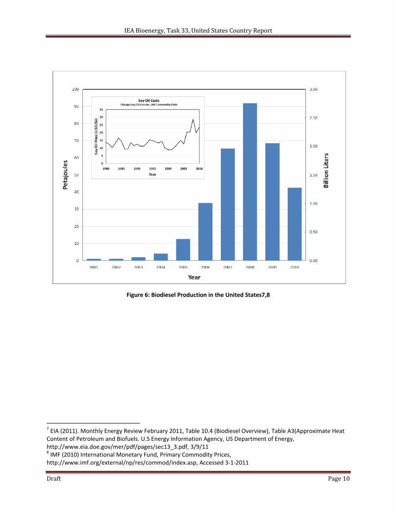
Historical biofuels production includes ethanol from corn (maize) and biodiesel from soybean oil. Historical ethanol production is shown in Figure 5, and historical biodiesel production is given in Figure 6.
0
10
20
30
40
50
60
70
0
2
4
6
8
10
12
1981 1984 1987 1990 1993 1996 1999 2002 2005 2008
Capacity
Generation
Capacity, Gigawatts Generation, TWh
IEA Bioenergy, Task 33, United States Country Report
Draft Page 8
Table 1: Biomass Capacity and Generation, EIA AEO 2006–2010a
Net Summer Capacity, GW 2003 2004 2005 2006 2007 2008b 2009b
Electric power sector
Municipal waste 3.19 3.19 3.21 3.39 3.42 3.43 3.43
Wood and other biomass 2.00 2.04 1.96 2.01 2.09 2.17 2.17
Total 5.19 5.23 5.17 5.40 5.51 5.60 5.60
End‐use generators
Municipal waste 0.27 0.33 0.34 0.33 0.33 0.33 0.33
Biomass 4.32 4.66 4.72 4.64 4.88 4.86 4.86
Total 4.59 4.99 5.06 4.97 5.21 5.19 5.19
Total, all sectors
Municipal wastes 3.46 3.52 3.55 3.72 3.75 3.76 3.76
Biomass 6.32 6.70 6.68 6.65 6.97 7.03 7.03
Total 9.78 10.22 10.23 10.37 10.72 10.79 10.79
Generation, TWh
Electric power sector
Biogenic municipal wastes 20.84 19.86 12.70 13.71 13.88 14.49 14.52
Wood and other biomass
Dedicated plants 9.53 8.54 8.60 8.42 8.65 9.00 4.66
Cofiring 0.00 1.19 1.97 1.91 1.94 1.90 1.76
Total 30.37 29.59 23.27 24.04 24.47 25.39 20.94
End‐use generators
Municipal wastes 2.22 2.64 1.95 1.98 2.01 2.02 2.79
Biomass 28.00 28.90 28.33 28.32 28.43 27.89 27.87
Total 30.22 31.54 30.28 30.30 30.44 29.91 30.66
Total, all sectors
Municipal wastes 23.06 22.50 14.65 15.69 15.89 16.51 17.31
Biomass 37.53 38.63 38.90 38.65 39.02 38.79 34.29
Total 60.59 61.13 53.55 54.34 54.91 55.30 51.60
EIA Form 923 Actual Generation (TWh) 55.40 55.06 54.34
a In 2003, cofiring plants classified as coal b Projected values from EIA 2010b
IEA Bioenergy, Task 33, United States Country Report
Draft Page 9
Figure 4: Map of biopower plant locations in United States
Source: POWERmap, Copyright 2010 Platts, a Division of the McGraw‐Hill Companies.
Figure 5: Ethanol Production in the United States
0
10
20
30
40
50
60
0.0
0.2
0.4
0.6
0.8
1.0
1.2
1.4
1981 1985 1990 1995 1996 1997 1998 1999 2000 2001 2002 2003 2004 2005 2006 2007 2008 2009 2010
Exajoules H
HV
Year
Billion Liters
EIA (2011). U.S. EIA Monthly Energy Review February 2011. USDOE, Washington, D.C.http://www.eia.doe.gov/mer/pdf/pages/sec10_7.pdf, Accessed 3/9/11
IEA Bioenergy, Task 33, United States Country Report
Draft Page 10
Figure 6: Biodiesel Production in the United States7,8
7 EIA (2011). Monthly Energy Review February 2011, Table 10.4 (Biodiesel Overview), Table A3(Approximate Heat Content of Petroleum and Biofuels. U.S Energy Information Agency, US Department of Energy, http://www.eia.doe.gov/mer/pdf/pages/sec13_3.pdf, 3/9/11 8 IMF (2010) International Monetary Fund, Primary Commodity Prices, http://www.imf.org/external/np/res/commod/index.asp, Accessed 3‐1‐2011
IEA Bioenergy, Task 33, United States Country Report
Draft Page 11
RESOURCE AVAILABILITY ESTIMATES
Biomass is plant‐derived material that stores light energy through photosynthesis9 (Wright et al. 2006). Depending on the type of plant matter, this energy can be stored as simple sugars, as starch, or as the
more complex structural compounds cellulose, 10 hemicellulose,
11 and lignin (collectively known as
lignocellulose). 12 Sugars and starches are primarily used for food, while lignocellulosic materials are
used primarily as construction materials and as an energy source. Biomass is unique among renewable energy resources in that it can be converted to carbon‐based fuels and chemicals as well as electric power.
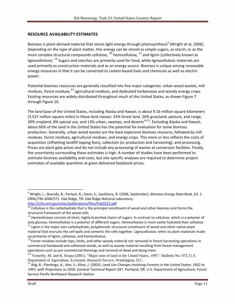
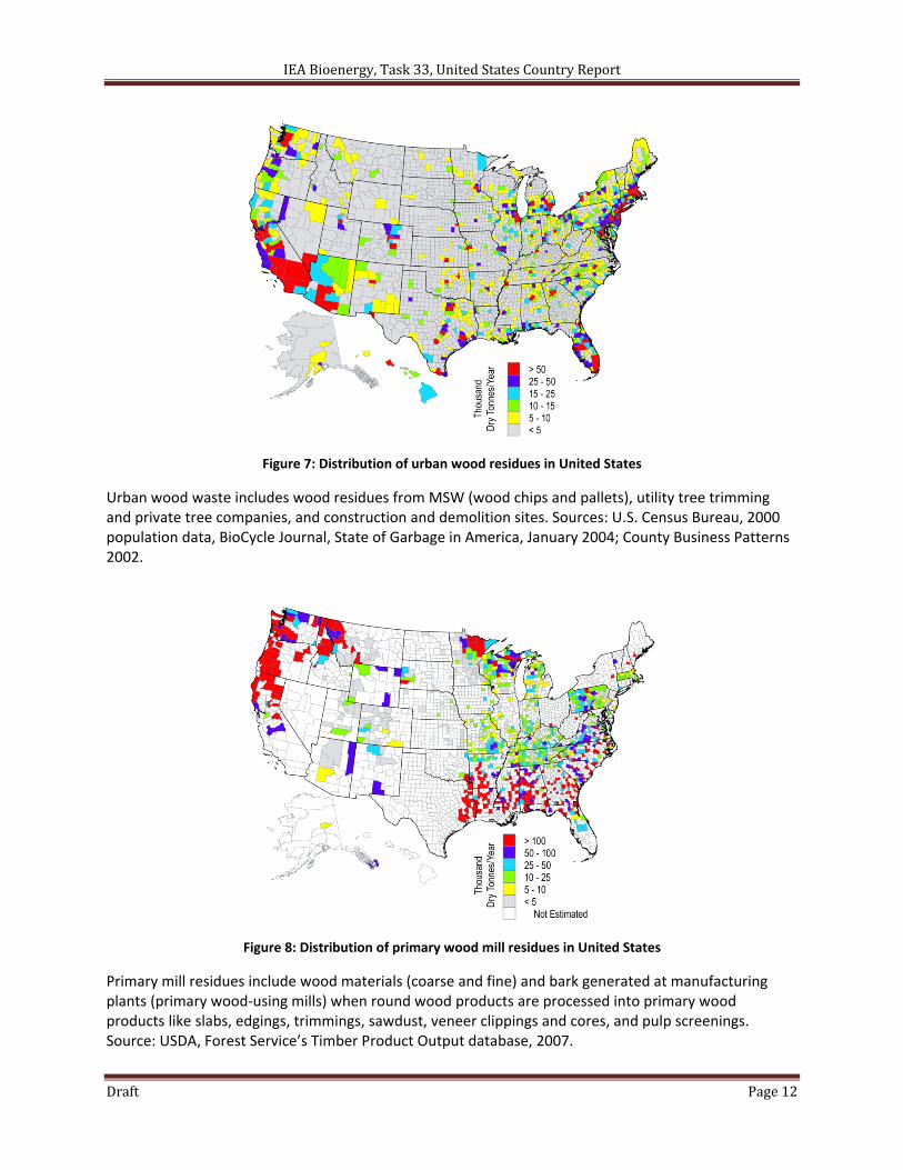
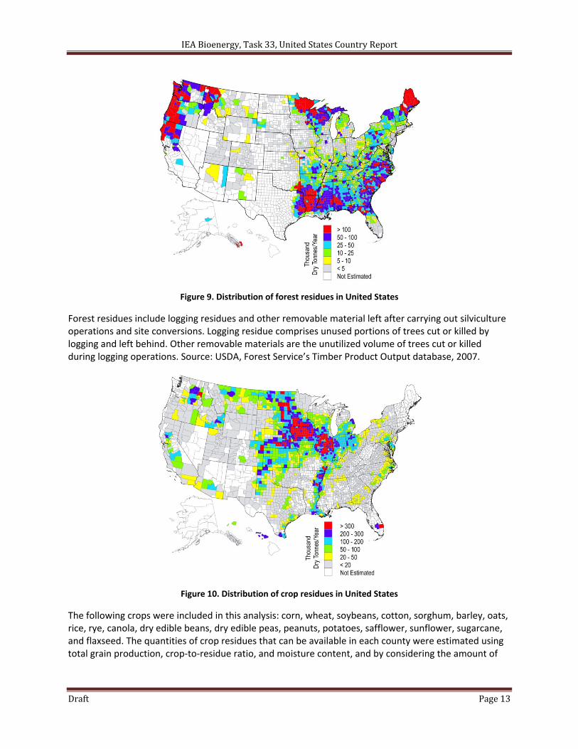
Potential biomass resources are generally classified into five major categories: urban wood wastes, mill
residues, forest residues,13 agricultural residues, and dedicated herbaceous and woody energy crops.
Existing resources are widely distributed throughout much of the United States, as shown Figure 7 through Figure 10.
The land base of the United States, including Alaska and Hawaii, is about 9.16 million square kilometers (3.537 million square miles) in these land classes: 33% forest land, 26% grassland, pasture, and range, 20% cropland, 8% special use, and 13% urban, swamps, and deserts14 15. Excluding Alaska and Hawaii, about 60% of the land in the United States has the potential for evaluation for some biomass production. Generally, urban wood wastes are the least expensive biomass resource, followed by mill residues, forest residues, agricultural residues, and energy crops. This more or less reflects the costs of acquisition (offsetting landfill tipping fees), collection (or production and harvesting), and processing. Prices are plant gate prices and do not include any processing of wastes at conversion facilities. Finally, the uncertainty surrounding these estimates is high. A number of studies have been performed to estimate biomass availability and costs, but site‐specific analyses are required to determine project estimates of available quantities at given delivered feedstock prices.
9 Wright, L.; Boundy, B.; Perlack, R.; Davis, S.; Saulsbury, B. (2006, September). Biomass Energy Data Book, Ed. 1. ORNL/TM‐2006/571. Oak Ridge, TN: Oak Ridge National Laboratory. http://info.ornl.gov/sites/publications/files/Pub3512.pdf 10 Cellulose is the carbohydrate that is the principal constituent of wood and other biomass and forms the structural framework of the wood cells. 11 Hemicellulose consists of short, highly branched chains of sugars. In contrast to cellulose, which is a polymer of only glucose, hemicellulose is a polymer of different sugars. Hemicellulose is more easily hydrated than cellulose. 12 Lignin is the major non‐carbohydrate, polyphenolic structural constituent of wood and other native plant material that encrusts the cell walls and cements the cells together. Lignocellulosic refers to plant materials made up primarily of lignin, cellulose, and hemicellulose. 13 Forest residues include tops, limbs, and other woody material not removed in forest harvesting operations in commercial hardwood and softwood stands, as well as woody material resulting from forest management operations such as pre‐commercial thinnings and removal of dead and dying trees.
14 Vesterby, M. and K. Krupa (2001). "Major uses of land in the United States, 1997," Bulletin No. 973, U.S. Department of Agriculture, Economic Research Service, Washington, D.C. 15 Alig, R.; Plantinga, A.; Ahn, S.; Kline, J. (2003). Land Use Changes Involving Forestry in the United States: 1952 to 1997, with Projections to 2050. General Technical Report 587. Portland, OR: U.S. Department of Agriculture, Forest Service Pacific Northwest Research Station
IEA Bioenergy, Task 33, United States Country Report
Draft Page 12
Figure 7: Distribution of urban wood residues in United States
Urban wood waste includes wood residues from MSW (wood chips and pallets), utility tree trimming and private tree companies, and construction and demolition sites. Sources: U.S. Census Bureau, 2000 population data, BioCycle Journal, State of Garbage in America, January 2004; County Business Patterns 2002.
Figure 8: Distribution of primary wood mill residues in United States
Primary mill residues include wood materials (coarse and fine) and bark generated at manufacturing plants (primary wood‐using mills) when round wood products are processed into primary wood products like slabs, edgings, trimmings, sawdust, veneer clippings and cores, and pulp screenings. Source: USDA, Forest Service’s Timber Product Output database, 2007.
IEA Bioenergy, Task 33, United States Country Report
Draft Page 13
Figure 9. Distribution of forest residues in United States
Forest residues include logging residues and other removable material left after carrying out silviculture operations and site conversions. Logging residue comprises unused portions of trees cut or killed by logging and left behind. Other removable materials are the unutilized volume of trees cut or killed during logging operations. Source: USDA, Forest Service’s Timber Product Output database, 2007.
Figure 10. Distribution of crop residues in United States
The following crops were included in this analysis: corn, wheat, soybeans, cotton, sorghum, barley, oats, rice, rye, canola, dry edible beans, dry edible peas, peanuts, potatoes, safflower, sunflower, sugarcane, and flaxseed. The quantities of crop residues that can be available in each county were estimated using total grain production, crop‐to‐residue ratio, and moisture content, and by considering the amount of
IEA Bioenergy, Task 33, United States Country Report
Draft Page 14
residue left on the field for soil protection, grazing, and other agricultural activities. Source: USDA, National Agricultural Statistics Service; 5‐year average: 2003–2007 data.
.
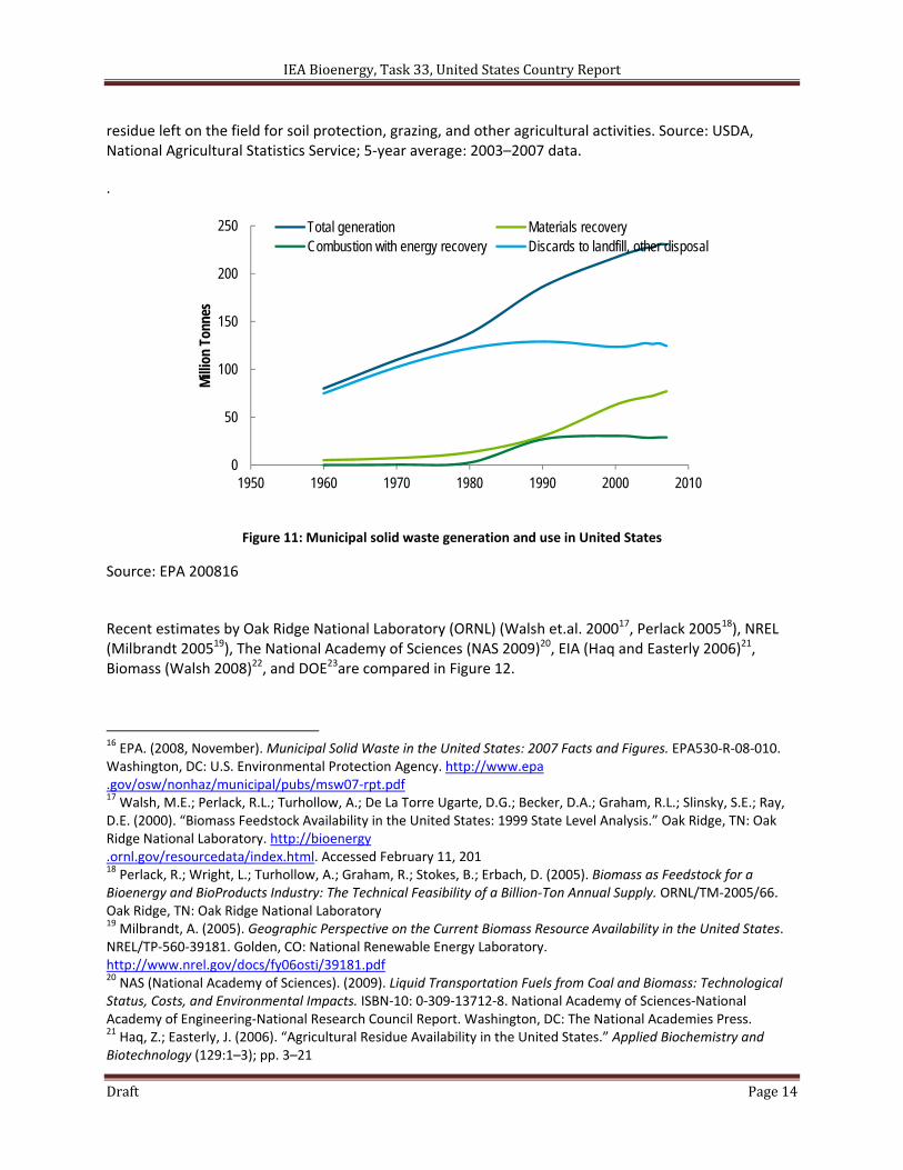
Figure 11: Municipal solid waste generation and use in United States
Source: EPA 200816
Recent estimates by Oak Ridge National Laboratory (ORNL) (Walsh et.al. 200017, Perlack 200518), NREL (Milbrandt 200519), The National Academy of Sciences (NAS 2009)20, EIA (Haq and Easterly 2006)21, Biomass (Walsh 2008)22, and DOE23are compared in Figure 12.
16 EPA. (2008, November). Municipal Solid Waste in the United States: 2007 Facts and Figures. EPA530‐R‐08‐010. Washington, DC: U.S. Environmental Protection Agency. http://www.epa .gov/osw/nonhaz/municipal/pubs/msw07‐rpt.pdf 17 Walsh, M.E.; Perlack, R.L.; Turhollow, A.; De La Torre Ugarte, D.G.; Becker, D.A.; Graham, R.L.; Slinsky, S.E.; Ray, D.E. (2000). “Biomass Feedstock Availability in the United States: 1999 State Level Analysis.” Oak Ridge, TN: Oak Ridge National Laboratory. http://bioenergy .ornl.gov/resourcedata/index.html. Accessed February 11, 201 18 Perlack, R.; Wright, L.; Turhollow, A.; Graham, R.; Stokes, B.; Erbach, D. (2005). Biomass as Feedstock for a Bioenergy and BioProducts Industry: The Technical Feasibility of a Billion‐Ton Annual Supply. ORNL/TM‐2005/66. Oak Ridge, TN: Oak Ridge National Laboratory 19 Milbrandt, A. (2005). Geographic Perspective on the Current Biomass Resource Availability in the United States. NREL/TP‐560‐39181. Golden, CO: National Renewable Energy Laboratory. http://www.nrel.gov/docs/fy06osti/39181.pdf 20 NAS (National Academy of Sciences). (2009). Liquid Transportation Fuels from Coal and Biomass: Technological Status, Costs, and Environmental Impacts. ISBN‐10: 0‐309‐13712‐8. National Academy of Sciences‐National Academy of Engineering‐National Research Council Report. Washington, DC: The National Academies Press. 21 Haq, Z.; Easterly, J. (2006). “Agricultural Residue Availability in the United States.” Applied Biochemistry and Biotechnology (129:1–3); pp. 3–21
0
50
100
150
200
250
1950 1960 1970 1980 1990 2000 2010
Mill
ion
Tonn
es
Total generation Materials recoveryCombustion with energy recovery Discards to landfill, other disposal
IEA Bioenergy, Task 33, United States Country Report
Draft Page 15
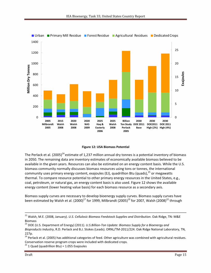
Figure 12: USA Biomass Potential
The Perlack et al. (2005)24 estimate of 1,237 million annual dry tonnes is a potential inventory of biomass in 2050. The remaining data are inventory estimates of economically available biomass believed to be available in the given years. Resources can also be estimated on an energy content basis. While the U.S. biomass community normally discusses biomass resources using tons or tonnes, the international community uses primary energy content, exajoules (EJ), quadrillion Btu (quads),25 or megawatts thermal. To compare resource potential to other primary energy resources in the United States, e.g., coal, petroleum, or natural gas, an energy content basis is also used. Figure 12 shows the available energy content (lower heating value basis) for each biomass resource as a secondary axis.
Biomass supply curves are necessary to develop bioenergy supply curves. Biomass supply curves have been estimated by Walsh et al. (2000)17 for 1999, Milbrandt (2005)19 for 2007, Walsh (2008)22 through
22 Walsh, M.E. (2008, January). U.S. Cellulosic Biomass Feedstock Supplies and Distribution. Oak Ridge, TN: M&E Biomass 23 DOE (U.S. Department of Energy) (2011). U.S.Billion‐Ton Update: Biomass Supply for a Bioenergy and Bioproducts Industry, R.D. Perlack and B.J. Stokes (Leads). ORNL/TM‐2011/224. Oak Ridge National Laboratory, TN, 227p. 24 Perlack et al. (2005) has additional categories of feed. Other agriculture was combined with agricultural residues. Conservation reserve program crops were included with dedicated crops. 25 1 Quad (quadrillion Btu) = 1.055 Exajoules
0
5
10
15
20
25
0
200
400
600
800
1000
1200
1400
2005Milbrandt
2005
2015Walsh2008
2020Walsh2008
2020NAS2009
2025Haq & Easterly2006
2025Walsh2008
BillionTon StudyPerlack 2005
2030DOE 2011Base
2030DOE2011High (2%)
2030DOE 2011High (4%)
Urban Primary Mill Residue Forest Residue Agricultural Residues Dedicated Crops
MillionDry Tonnes
Exajoules
IEA Bioenergy, Task 33, United States Country Report
Draft Page 16
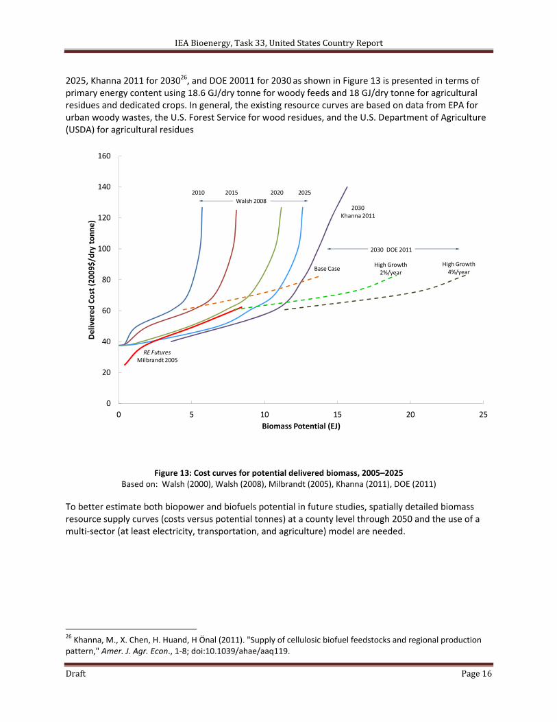
2025, Khanna 2011 for 203026, and DOE 20011 for 2030 as shown in Figure 13 is presented in terms of primary energy content using 18.6 GJ/dry tonne for woody feeds and 18 GJ/dry tonne for agricultural residues and dedicated crops. In general, the existing resource curves are based on data from EPA for urban woody wastes, the U.S. Forest Service for wood residues, and the U.S. Department of Agriculture (USDA) for agricultural residues
Figure 13: Cost curves for potential delivered biomass, 2005–2025 Based on: Walsh (2000), Walsh (2008), Milbrandt (2005), Khanna (2011), DOE (2011)
To better estimate both biopower and biofuels potential in future studies, spatially detailed biomass resource supply curves (costs versus potential tonnes) at a county level through 2050 and the use of a multi‐sector (at least electricity, transportation, and agriculture) model are needed.
26 Khanna, M., X. Chen, H. Huand, H Önal (2011). "Supply of cellulosic biofuel feedstocks and regional production pattern," Amer. J. Agr. Econ., 1‐8; doi:10.1039/ahae/aaq119.
0
20
40
60
80
100
120
140
160
0 5 10 15 20 25
Delivered Cost (2009$/dry tonne)
Biomass Potential (EJ)
2010 2015 2020 2025
RE FuturesMilbrandt 2005
2030Khanna 2011
Base CaseHigh Growth2%/year
High Growth4%/year
Walsh 2008
2030 DOE 2011
IEA Bioenergy, Task 33, United States Country Report
Draft Page 17
BIOMASS GASIFICATION OVERVIEW
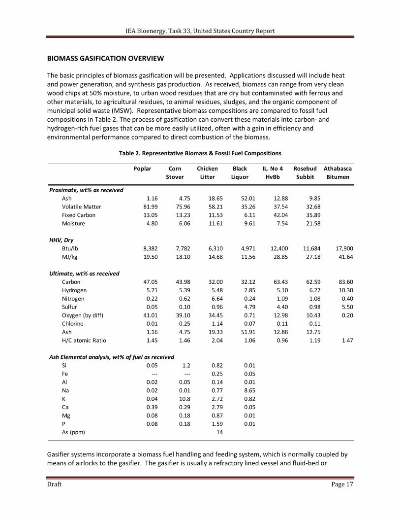
The basic principles of biomass gasification will be presented. Applications discussed will include heat and power generation, and synthesis gas production. As received, biomass can range from very clean wood chips at 50% moisture, to urban wood residues that are dry but contaminated with ferrous and other materials, to agricultural residues, to animal residues, sludges, and the organic component of municipal solid waste (MSW). Representative biomass compositions are compared to fossil fuel compositions in Table 2. The process of gasification can convert these materials into carbon‐ and hydrogen‐rich fuel gases that can be more easily utilized, often with a gain in efficiency and environmental performance compared to direct combustion of the biomass.
Table 2. Representative Biomass & Fossil Fuel Compositions
Gasifier systems incorporate a biomass fuel handling and feeding system, which is normally coupled by means of airlocks to the gasifier. The gasifier is usually a refractory lined vessel and fluid‐bed or
Poplar Corn
Stover
Chicken
Litter
Black
Liquor
IL. No 4
HvBb
Rosebud
Subbit
Athabasca
Bitumen
Proximate, wt% as received
Ash 1.16 4.75 18.65 52.01 12.88 9.85
Volatile Matter 81.99 75.96 58.21 35.26 37.54 32.68
Fixed Carbon 13.05 13.23 11.53 6.11 42.04 35.89
Moisture 4.80 6.06 11.61 9.61 7.54 21.58
HHV, Dry
Btu/lb 8,382 7,782 6,310 4,971 12,400 11,684 17,900
MJ/kg 19.50 18.10 14.68 11.56 28.85 27.18 41.64
Ultimate, wt% as received
Carbon 47.05 43.98 32.00 32.12 63.43 62.59 83.60
Hydrogen 5.71 5.39 5.48 2.85 5.10 6.27 10.30
Nitrogen 0.22 0.62 6.64 0.24 1.09 1.08 0.40
Sulfur 0.05 0.10 0.96 4.79 4.40 0.98 5.50
Oxygen (by diff) 41.01 39.10 34.45 0.71 12.98 10.43 0.20
Chlorine 0.01 0.25 1.14 0.07 0.11 0.11
Ash 1.16 4.75 19.33 51.91 12.88 12.75
H/C atomic Ratio 1.45 1.46 2.04 1.06 0.96 1.19 1.47
Ash Elemental analysis, wt% of fuel as received
Si 0.05 1.2 0.82 0.01
Fe ‐‐‐ ‐‐‐ 0.25 0.05
Al 0.02 0.05 0.14 0.01
Na 0.02 0.01 0.77 8.65
K 0.04 10.8 2.72 0.82
Ca 0.39 0.29 2.79 0.05
Mg 0.08 0.18 0.87 0.01
P 0.08 0.18 1.59 0.01
As (ppm) 14
IEA Bioenergy, Task 33, United States Country Report
Draft Page 18
entrained‐flow gasification is carried at temperatures of 750‐850ºC at either atmospheric or elevated pressures. The product gas has to be treated so it matches the end‐use application. For close‐coupled gasifier‐combustor systems there is no cleanup of the gases. For gas turbine applications in a power system the gas has to be free of particulates, tars, sulfur, chlorine compounds, and alkali metals to ensure the integrity of the turbine hot section. For internal combustion engines the gas must be cooled to ensure that a sufficient charge of energy can be put into each cylinder; and particular attention has to be given to tar and particulate contents to ensure that the valves and cylinders are protected. Fuel cell applications require the gas to be mainly hydrogen without any significant sulfur or chloride contamination to protect the electrodes. For synthesis operations such as methanol and hydrogen production, particulates and other contaminants (H2S, etc.) must be removed to prevent poisoning of downstream catalysts.
The process efficiency is high; gasification is typically 80‐85% thermodynamically efficient in converting the organic content of the feed into a fuel gas mixture. Because biomass gasification results in a clean fuel gas, the efficiency is further enhanced by the use of combined cycles to generate electricity; biomass‐to‐electricity efficiencies greater than 45% are forecast. If the gases are converted to hydrogen, the limiting efficiency with fuel cells may be over 55%. The environmental advantage is that the fuel gas is a much smaller volume to be processed than the combustion stream from a boiler; this and the generally lower treatment temperature of the biomass results in retention of metals (including alkali) in the ash and cyclone as salts that can be disposed. The gas can easily be cleaned of acid gas components, including hydrogen chloride, before combustion and thus is environmentally superior to direct combustion.
Biomass is a complex mixture of organic compounds and polymers 27. The major types of compounds are lignin and carbohydrates (cellulose and hemicellulose) whose ratios and resulting properties are species dependent. Lignin, the cementing agent for cellulose, is a complex polymer of phenylpropane units. Cellulose is a polymer formed from d(+)‐glucose; the hemicellulose polymer is based on hexose and pentose sugars. Biomass such as wood typically has low ash, nitrogen, and sulfur contents. However, some agricultural materials such as straws and grasses have substantially higher amounts. To estimate yields during gasification the complex material must be reduced to a simplified chemical formula, such as CH1.4O0.6. In this discussion, elements such as sulfur and nitrogen are considered to be present in very small amounts, and are not considered in terms of overall chemistry.
The combustion of biomass can be ideally represented by:
OHCOOOCH 2226.04.1 7.005.1
Oxygen‐blown gasification can be thought of as incomplete combustion or partial oxidation. Gasification using a minimum amount of oxygen can be represented by:
OHCOOOCH 226.04.1 7.02.0
27 Graboski, M. and R. Bain (1981). "Properties of biomass relevant to gasification," in Biomass Gasification, Principles and Technology (e. T. Reed), Noyes Data corporation, Park Ridge, NJ, pp41 – 71 (ISBN 0‐8185‐0852‐2).
IEA Bioenergy, Task 33, United States Country Report
Draft Page 19
In cases where no oxygen is used the gasification reaction can be represented by:
OHCCOOCH 26.04.1 7.04.06.0
This pyrolysis reaction is endothermic, and heat is needed to make the reaction proceed. This heat is provided by the oxidation reactions shown above or by indirect heat transfer. Although these ideal reactions are simple, actual gasification is more complex. Intermediate compounds such as tars and methane are formed that must be further processed if the synthesis gas is be used to produce methanol or hydrogen.
Gasifier Medium
Gasification involves the thermal destruction of biomass in a reducing atmosphere of steam or air (or both) to produce a medium‐ or low‐calorific value gas. If air is present, the ratio of oxygen to biomass is typically around 0.3. Air‐blown, or directly heated gasifiers, use the exothermic reaction between oxygen and organics to provide the heat necessary to devolatilize biomass and to convert residual carbon‐rich chars. For directly heated gasifiers, the heat to drive the process is generated inside within the gasifier. When air is used, the product gas is diluted with nitrogen and typically has a dry‐basis calorific value of 5‐6 MJ/Nm3. The dry‐basis calorific value of the product gas can be increased to 13‐14 MJ/Nm3 using oxygen instead of air. Oxygen production is expensive, however, and its use has been proposed only for applications involving the production of synthesis gas where nitrogen is not permitted in downstream synthesis conversion operations. Indirectly heated gasifiers heat and gasify biomass through heat transfer from a hot solid or through a heat transfer surface. Because air is not introduced into the gasifier, little nitrogen is present and a medium‐calorific gas is produced; dry‐basis values of 18‐20 MJ/Nm3 are typical.
Pressure
A second variable affecting gasification‐based power systems performance is operating pressure. Most gasification power applications will involve a gas turbine‐based generation cycle. Turbines typically operate at compression ratios of 10 to 20, giving turbine inlet pressures of 1.0‐2.5 MPa. A pressurized gasifier will produce gas at a pressure suitable for direct turbine application and provide the highest overall process efficiency, but process improvements are needed. Reliable, high‐pressure feed systems have not been commercially proven. At gasifier conditions (825ºC and 2 MPa) tars, chars, and volatile alkalis are generated. To maximize efficiency, these materials must be removed from the hot product gas without lowering the temperature below the tar dew point, typically about 540ºC. Thus, hot‐gas cleanup systems are required. Tars have relatively high heat contents and can be burned in combustors, but they may plug char filters and may form soot during combustion. Therefore, the first element of a hot gas cleanup system will probably be a catalytic or thermal tar cracker. A catalytic tar cracker will operate at temperatures comparable to gasifier temperature, about 825ºC; a thermal cracker will typically operate at 870‐980ºC. After the tar cracker, the product gas will be partially cooled to minimize the amount of alkali vapors, typically to 350‐650ºC. The product will then pass through a filter to remove solids. Much of the alkali will also be removed. For gas turbine applications the gas may still contain too much alkali. Gas turbine limits for alkali are about 25 ppb in the turbine combustor exit gas.
IEA Bioenergy, Task 33, United States Country Report
Draft Page 20
To ensure that the product gas meets gas turbine manufacturer alkali specifications, an alkali getter bed may be added after the filter. Typical bed materials are emalthite or hectorite.
Alternatively, the gasifier can be operated at low pressure and the cleaned product gas compressed to the pressure required for gas turbine application. In this case a tar cracker will probably be used to minimize the amount of tar that must be handled during quenching. The product gas exiting the tar cracker will be conditioned to provide a suitable compressor feed. Gas characteristics to be considered for compressor use include the amount of condensable or soluble tar and the water vapor content. The water and tar content must be low enough to ensure no condensation during compression. Also, soluble tars that will affect lubrication oil properties must be eliminated. Lastly, the gas inlet temperature must be suitable for compressor materials of construction. Normally, the temperature should be held below about 90ºC. Usually a combination of heat exchange (to reduce the gas from tar cracker exit temperature to residual tar dew point) and wet scrubbing are used. The water vapor content will be at saturation at scrubber exit temperature and pressure.
Gasifier Type
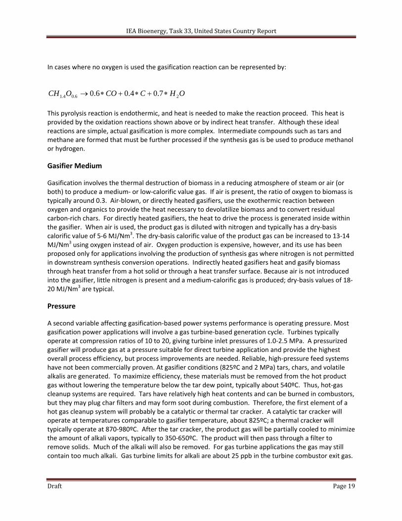
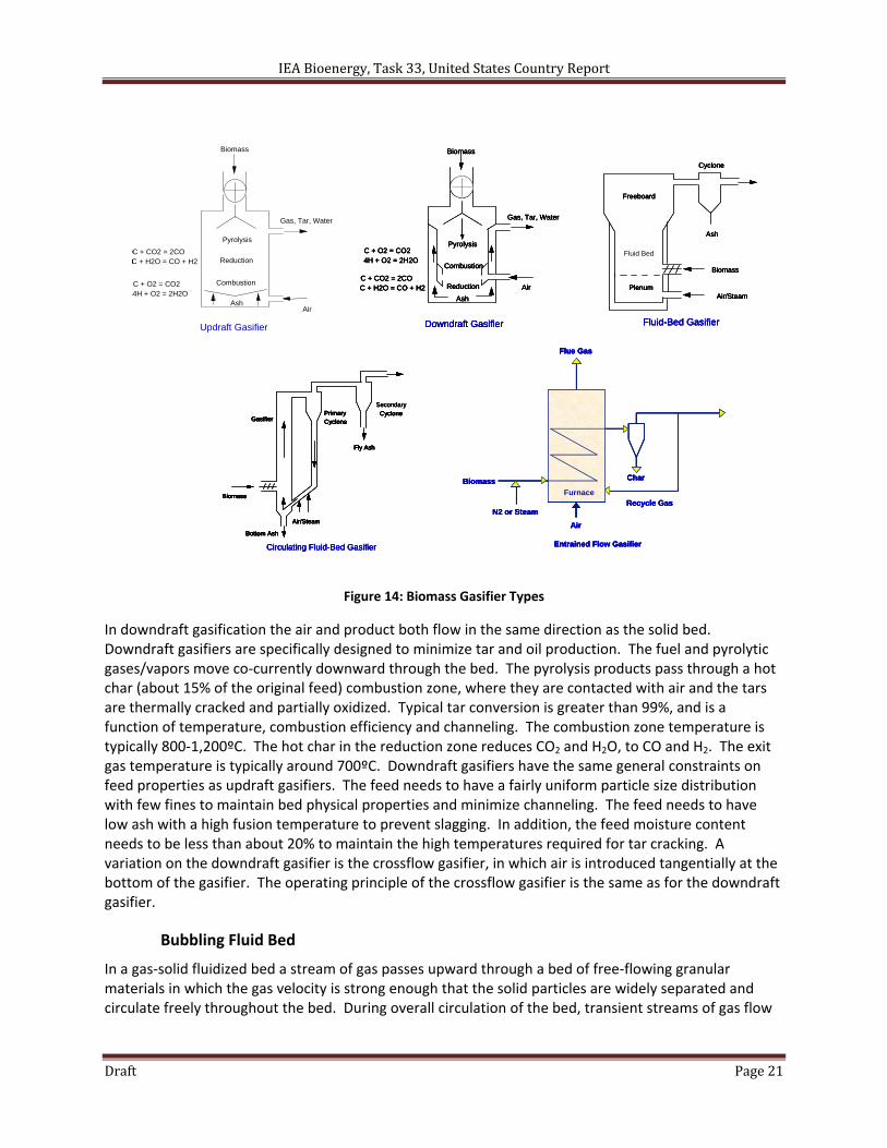
The other major variable is reactor type. Four primary types of biomass gasification reactor systems have been developed: fixed‐bed reactors, bubbling fluid‐bed reactors, circulating fluid‐bed reactors, and entrained‐flow reactors. Simple schematics of the various gasifiers are shown in Figure 14.
Fixed Bed
Fixed‐bed gasifiers can be classified primarily as updraft and downdraft. Updraft gasifiers represent the oldest and simplest gasifiers. The updraft gasifier is a counterflow reactor in which fuel is introduced into the top by means of a lock hopper or rotary valve and flows downward through the reactor to a grate where ash is removed. The gasifying medium, air or oxygen and possibly steam, is introduced below the grate and flows upward through the reactor. At the bottom of the reactor (combustion zone) char burns to form carbon dioxide (CO2) and steam (H2O), which then flow upward through the bed countercurrently to the downflowing solids. The exothermic combustion reactions supply the energy to drive gasification, pyrolysis and drying. The maximum temperature in the combustion zone is typically higher than 1,200ºC. In the reduction zone CO2 and H2O are partially reduced to carbon monoxide (CO) and hydrogen (H2) through reaction with carbon in the char at temperatures of 800‐1,200ºC. In the pyrolysis zone these gases contact dry biomass in the temperature range of 400‐800º C and devolatilize the biomass to produce pyrolysis products and residual char. Above this zone the gases and pyrolytic vapors dry the wet biomass. Typical product exit temperatures are 80‐100ºC. A wide range of tars and oils, which can condense in product lines, are produced in the pyrolysis zone. For this reason updraft gasifiers are usually operated in a close‐coupled mode to a furnace or boiler to produce steam or hot water. Certain feeds with low‐melting ash may have slagging on the combustion grate. In addition, feed particle size needs to be controlled to maintain a uniform bed.
IEA Bioenergy, Task 33, United States Country Report
Draft Page 21
Figure 14: Biomass Gasifier Types
In downdraft gasification the air and product both flow in the same direction as the solid bed. Downdraft gasifiers are specifically designed to minimize tar and oil production. The fuel and pyrolytic gases/vapors move co‐currently downward through the bed. The pyrolysis products pass through a hot char (about 15% of the original feed) combustion zone, where they are contacted with air and the tars are thermally cracked and partially oxidized. Typical tar conversion is greater than 99%, and is a function of temperature, combustion efficiency and channeling. The combustion zone temperature is typically 800‐1,200ºC. The hot char in the reduction zone reduces CO2 and H2O, to CO and H2. The exit gas temperature is typically around 700ºC. Downdraft gasifiers have the same general constraints on feed properties as updraft gasifiers. The feed needs to have a fairly uniform particle size distribution with few fines to maintain bed physical properties and minimize channeling. The feed needs to have low ash with a high fusion temperature to prevent slagging. In addition, the feed moisture content needs to be less than about 20% to maintain the high temperatures required for tar cracking. A variation on the downdraft gasifier is the crossflow gasifier, in which air is introduced tangentially at the bottom of the gasifier. The operating principle of the crossflow gasifier is the same as for the downdraft gasifier.
Bubbling Fluid Bed
In a gas‐solid fluidized bed a stream of gas passes upward through a bed of free‐flowing granular materials in which the gas velocity is strong enough that the solid particles are widely separated and circulate freely throughout the bed. During overall circulation of the bed, transient streams of gas flow
Pyrolysis
Reduction
Combustion
Gas, Tar, Water
Ash
Biomass
Air
C + CO2 = 2COC + H2O = CO + H2
C + O2 = CO24H + O2 = 2H2O
Updraft Gasifier
Pyrolysis
Reduction
Combustion
Gas, Tar, Water
Ash
Biomass
Air
C + CO2 = 2COC + H2O = CO + H2
C + O2 = CO24H + O2 = 2H2O
Updraft Gasifier
Freeboard
Fluid Bed
PlenumAir/Steam
Biomass
Ash
Cyclone
Fluid-Bed Gasifier
Freeboard
Fluid Bed
PlenumAir/Steam
Biomass
Ash
Cyclone
Fluid-Bed Gasifier
Secondary
Circulating Fluid-Bed Gasifier
Fly Ash
Bottom Ash
Biomass
Air/Steam
GasifierPrimaryCyclone
CycloneSecondary
Circulating Fluid-Bed Gasifier
Fly Ash
Bottom Ash
Biomass
Air/Steam
GasifierPrimaryCyclone
Cyclone
Fly Ash
Bottom Ash
Biomass
Air/Steam
GasifierPrimaryCyclone
Cyclone
Biomass
Pyrolysis
Reduction
Combustion
Gas, Tar, Water
Ash
AirC + CO2 = 2COC + H2O = CO + H2
C + O2 = CO24H + O2 = 2H2O
Downdraft Gasifier
Biomass
Pyrolysis
Reduction
Combustion
Gas, Tar, Water
Ash
AirC + CO2 = 2COC + H2O = CO + H2
C + O2 = CO24H + O2 = 2H2O
Downdraft Gasifier
Biomass
N2 or Steam
Furnace
Char
Recycle Gas
Flue Gas
Entrained Flow Gasifier
Air
Biomass
N2 or Steam
Furnace
Char
Recycle Gas
Flue Gas
Entrained Flow Gasifier
Air
Pyrolysis
Reduction
Combustion
Gas, Tar, Water
Ash
Biomass
Air
C + CO2 = 2COC + H2O = CO + H2
C + O2 = CO24H + O2 = 2H2O
Updraft Gasifier
Pyrolysis
Reduction
Combustion
Gas, Tar, Water
Ash
Biomass
Air
C + CO2 = 2COC + H2O = CO + H2
C + O2 = CO24H + O2 = 2H2O
Updraft Gasifier
Freeboard
Fluid Bed
PlenumAir/Steam
Biomass
Ash
Cyclone
Fluid-Bed Gasifier
Freeboard
Fluid Bed
PlenumAir/Steam
Biomass
Ash
Cyclone
Fluid-Bed Gasifier
Secondary
Circulating Fluid-Bed Gasifier
Fly Ash
Bottom Ash
Biomass
Air/Steam
GasifierPrimaryCyclone
CycloneSecondary
Circulating Fluid-Bed Gasifier
Fly Ash
Bottom Ash
Biomass
Air/Steam
GasifierPrimaryCyclone
Cyclone
Fly Ash
Bottom Ash
Biomass
Air/Steam
GasifierPrimaryCyclone
Cyclone
Biomass
Pyrolysis
Reduction
Combustion
Gas, Tar, Water
Ash
AirC + CO2 = 2COC + H2O = CO + H2
C + O2 = CO24H + O2 = 2H2O
Downdraft Gasifier
Biomass
Pyrolysis
Reduction
Combustion
Gas, Tar, Water
Ash
AirC + CO2 = 2COC + H2O = CO + H2
C + O2 = CO24H + O2 = 2H2O
Downdraft Gasifier
Biomass
N2 or Steam
Furnace
Char
Recycle Gas
Flue Gas
Entrained Flow Gasifier
Air
Biomass
N2 or Steam
Furnace
Char
Recycle Gas
Flue Gas
Entrained Flow Gasifier
Air
IEA Bioenergy, Task 33, United States Country Report
Draft Page 22
upward in channels containing few solids, and clumps or masses of solids flow downward28. The fluidized bed looks like a boiling liquid and has the physical properties of a fluid. In fluidized‐bed gasification of biomass the gas is air, oxygen, or steam, and the bed is usually sand, limestone, dolomite, or alumina. The gas acts as the fluidizing medium, and if air/oxygen is used, is the oxidant for biomass partial oxidation. A fluidized‐bed gasifier is a vessel with dimensions such that the superficial velocity of the gas maintains the bed in a fluidized condition at the bottom of the vessel, with a change in cross‐sectional area above the bed that lowers the superficial gas velocity below fluidization velocity to maintain bed inventory and act as a disengaging zone. To obtain the total desired gas‐phase residence time for complete devolatilization, the larger cross‐sectional‐area zone (usually referred to as the freeboard) is extended. A cyclone is used to either return fines to the bed or to remove ash‐rich fines from the system. A gas distribution manifold or series of sparge tubes are used to fluidize the bed29. Biomass is introduced either through a feed chute to the top of the bed or through an auger into the bed. In‐bed introduction provides residence time for fines that would otherwise be entrained in the fluidizing gas and not converted in the bed.
The bed is usually preheated using an external burner fired by natural gas, propane or fuel oil. The hot flue gas from the external burner is used to heat the fluidized bed to the fuel ignition temperature. For biomass this temperature is around 540ºC. Supplemental firing can be used to heat the freeboard gas to normal gasification temperature. At this point biomass is slowly introduced into the bed to raise the bed temperature to the desired operating range, normally 790‐870ºC. Bed temperature is governed by the desire to obtain complete devolatilization versus the need to maintain the bed temperature below the ash‐fusion temperature of the biomass ash. As biomass is introduced into the bed, most of the organics pyrolytically vaporize and are partially combusted in the bed. The exothermic combustion provides the heat to maintain the bed at temperature and to volatilize additional biomass. Fluidized‐bed gasifiers have the advantage of extremely good mixing and high heat transfer, resulting in very uniform bed conditions. Gasification is very efficient, and 95%‐99% carbon conversion is typical. Bubbling fluidized‐bed gasifiers are normally designed for complete ash carryover, necessitating the addition of cyclones for particulate control.
Circulating Fluid Bed
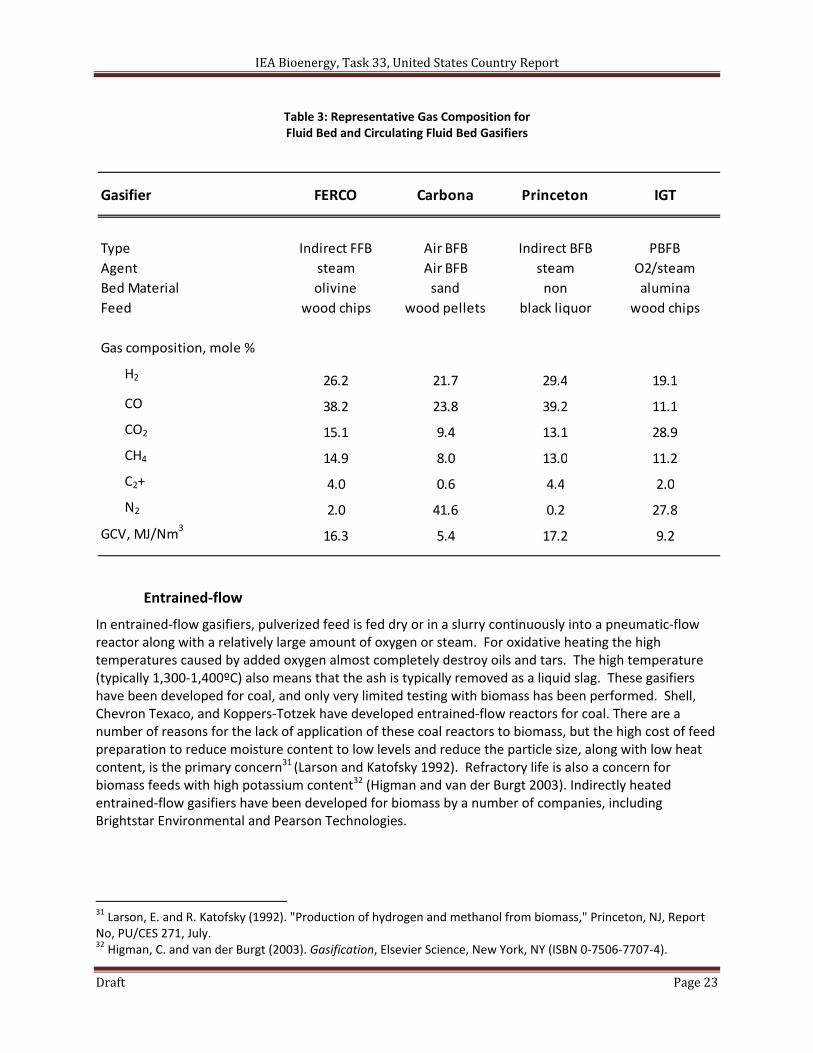
If the gas flow of a bubbling fluid bed is increased, the gas bubbles become larger, forming large voids in the bed and entraining substantial amounts of solids. This type of bed is referred to as a turbulent fluid bed30 (Babcock and Wilcox 1992). In a circulating fluid bed the turbulent bed solids are collected, separated from the gas, and returned to the bed, forming a solids circulation loop. A circulating fluid bed can be differentiated from a bubbling fluid bed in that there is no distinct separation between the dense solids zone and the dilute solids zone. Circulating fluid‐bed densities are about 560 kg/m3 compared to a bubbling‐bed density of 720 kg/m3 30. To achieve the lower bed density, gas rates are increased from the 1.5‐3.7 m/s of bubbling beds to about 9.1 m/s. The residence time of the solids in a circulating fluid bed is determined by the solids circulation rate, the attrition of the solids, and the collection efficiency of the solids separation device. Typical gas compositions for fluid and circulating fluid bed gasifiers are shown in Table 2.
28 Perry, R and C. Chilton (1973). Chemical Engineer's Handbook, 5th ed., McGraw‐Hill, New York, NY. 29 Hansen, J. (1992). "Fluidized bed combustion of biomass; an overview," in Biomass Combustion Conference, Reno Nevada, USDOE Western Regional Biomass energy Program, January 28‐30. 30 Babcock and Wilcox (1992). "Atmospheric pressure boilers," in Steam: Its Generation and Use (ed. S. Stulz and J. Kitto), 40th ed., Babcock and Wilcox, Barberton, Ohio, Chapter 16.
IEA Bioenergy, Task 33, United States Country Report
Draft Page 23
Table 3: Representative Gas Composition for Fluid Bed and Circulating Fluid Bed Gasifiers
Entrained‐flow
In entrained‐flow gasifiers, pulverized feed is fed dry or in a slurry continuously into a pneumatic‐flow reactor along with a relatively large amount of oxygen or steam. For oxidative heating the high temperatures caused by added oxygen almost completely destroy oils and tars. The high temperature (typically 1,300‐1,400ºC) also means that the ash is typically removed as a liquid slag. These gasifiers have been developed for coal, and only very limited testing with biomass has been performed. Shell, Chevron Texaco, and Koppers‐Totzek have developed entrained‐flow reactors for coal. There are a number of reasons for the lack of application of these coal reactors to biomass, but the high cost of feed preparation to reduce moisture content to low levels and reduce the particle size, along with low heat content, is the primary concern31 (Larson and Katofsky 1992). Refractory life is also a concern for biomass feeds with high potassium content32 (Higman and van der Burgt 2003). Indirectly heated entrained‐flow gasifiers have been developed for biomass by a number of companies, including Brightstar Environmental and Pearson Technologies.
31 Larson, E. and R. Katofsky (1992). "Production of hydrogen and methanol from biomass," Princeton, NJ, Report No, PU/CES 271, July. 32 Higman, C. and van der Burgt (2003). Gasification, Elsevier Science, New York, NY (ISBN 0‐7506‐7707‐4).
Gasifier FERCO Carbona Princeton IGT
Type Indirect FFB Air BFB Indirect BFB PBFB
Agent steam Air BFB steam O2/steam
Bed Material olivine sand non alumina
Feed wood chips wood pellets black liquor wood chips
Gas composition, mole %
H2 26.2 21.7 29.4 19.1
CO 38.2 23.8 39.2 11.1
CO2 15.1 9.4 13.1 28.9
CH4 14.9 8.0 13.0 11.2
C2+ 4.0 0.6 4.4 2.0
N2 2.0 41.6 0.2 27.8
GCV, MJ/Nm3
16.3 5.4 17.2 9.2
IEA Bioenergy, Task 33, United States Country Report
Draft Page 24
USDOE INTEGRATED BIREFINERY PROJECTS
The U.S. Department of Energy (USDOE) works in partnership with industry to develop, build, operate, and validate integrated biorefineries at pilot scale (at least one dry metric tonne per day), demonstration scale (at least 50 metric tonne per day), and commercial scale (a minimum of 700 metric tonnes per day) with the objectives of proving the viability of various feedstock and conversion pathways and reducing the technical and financial risks of technology commercialization. Projects are strategically located in various areas of the country to promote local and regional economic development with conversion technologies optimized for the biomass feedstocks in each region. The biofuels technologies supported include biochemical conversion processes, thermochemical conversion processes, hybrid processes, and algae processes. To date USDOE has invested in twelve pilot processes, nine demonstration projects, and six commercial biorefineries.
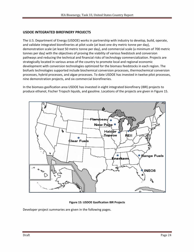
In the biomass gasification area USDOE has invested in eight integrated biorefinery (IBR) projects to produce ethanol, Fischer Tropsch liquids, and gasoline. Locations of the projects are given in Figure 15.
Figure 15: USDOE Gasification IBR Projects
Developer project summaries are given in the following pages.
IEA Bioenergy, Task 33, United States Country Report
Draft Page 25
IEA Bioenergy, Task 33, United States Country Report
Draft Page 26
IEA Bioenergy, Task 33, United States Country Report
Draft Page 27
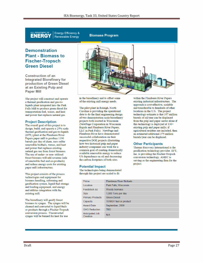
IEA Bioenergy, Task 33, United States Country Report
Draft Page 28
IEA Bioenergy, Task 33, United States Country Report
Draft Page 29
IEA Bioenergy, Task 33, United States Country Report
Draft Page 30
IEA Bioenergy, Task 33, United States Country Report
Draft Page 31
IEA Bioenergy, Task 33, United States Country Report
Draft Page 32
IEA Bioenergy, Task 33, United States Country Report
Draft Page 33
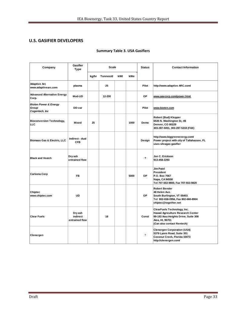
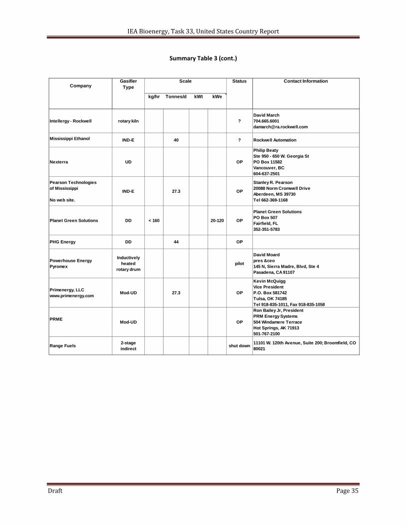
U.S. GASIFIER DEVELOPERS
Summary Table 3. USA Gasifiers
CompanyGasifier
TypeStatus Contact Information
kg/hr Tonnes/d kWt kWe
Adaptive Arcwww.adaptivearc.com
plasma 25 Pilot http://www.adaptive ARC.com/
Advanced Alternative Energy Corp.
Mod-UD 12-200 OP www.aaecorp.com/power.html
Bioten Power & Energy GroupCogentech, Inc
DD-var Pilot www.bioten.com
Bioconversion Technology, LLC
Mixed 25 1000 Demo
Robert (Bud) Klepper6535 N. Washington St, #BDenver, CO 80229303-287-5001, 303-287-5318 (FAX)
Biomass Gas & Electric, LLCIndirect - dual
CFBDesign
http://www.biggreenenergy.com/Power project with city of Tallahassee, FLuses silvagas gasifier
Black and VeatchDry ash entrained flow
?Jon C. Erickson913-458-2293
Carbona CorpFB 5000 OP
Jim PatelPresidentP.O. Box 7067Napa, CA 94558Tel 707-553-9800, Fax 707-553-9820
Chiptecwww.chiptec.com UD OP
Robert Bender48 Helen Ave.South Burlington, VT 05403Tel 802-658-0956, Fax [email protected]
Clear FuelsDry ash indirect
entrained flow18 Const
ClearFuels Technology, Inc.Hawaii Agriculture Research Center99-193 Aiea Heights Drive, Suite 308Aiea, HI, 96701(Can also contact Rentech)
Clenergen ?
Clenergen Corporation (USA)5379 Lyons Road, Suite 301Coconut Creek, Florida 33073http://clenergen.com/
Scale
IEA Bioenergy, Task 33, United States Country Report
Draft Page 34
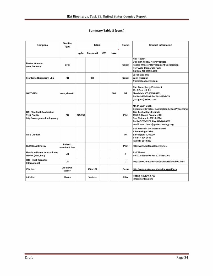
Summary Table 3 (cont.)
CompanyGasifier
TypeStatus Contact Information
kg/hr Tonnes/d kWt kWe
Foster Wheelerwww.fwe.com
CFB Comm
Neil RaskinDirector, Global New ProductsFoster Wheeler Development CorporationPerryville Corporate ParkClinton, NJ 08890-4000
FrontLine Bioenergy, LLC FB 68 CommJerod SmeenkJohn Reardonfronlinebioenergy.com
GAZOGEN rotary hearth 100 OP
Carl Bielenberg, President1915 East Hill RdMarshfield VT 05658-8901Tel 802-456-8993 Fax [email protected]
GTI Flex-Fuel Gasification Test Facilityhttp://www.gastechnology.org
FB 375-750 Pilot
Mr. P. Vann BushExecutive Director, Gasification & Gas ProcessingGas Technology Institute1700 S. Mount Prospect RdDes Plaines, IL 60018-1804Tel 847-768-0973, Fax 847-768-0507email: [email protected]
GTS Duratek OP
Bob Hensel - V-P International 6 Stoneridge DriveBarrington, IL 60010Tel 847-304-9646Fax 847-304-5889
Gulf Coast Energyindirect
entrained flowPilot http://www.gulfcoastenergy.net/
Hamilton Mauer International/MIFGA (HMI, Inc.)
UD ?Rolf MauerTel 713-468-6805 Fax 713-468-0761
HTI - Heat Transfer International
UD ? http://www.heatxfer.com/products/fixedbed.html
ICM Inc.Air-blown
Auger136 - 181 Demo http://www.icminc.com/services/gasifiers
InEnTec Plasma Various PiliotPhone (509)[email protected]
Scale
IEA Bioenergy, Task 33, United States Country Report
Draft Page 35
Summary Table 3 (cont.)
CompanyGasifier
TypeStatus Contact Information
kg/hr Tonnes/d kWt kWe
Intellergy - Rockwell rotary kiln ?David [email protected]
Mississippi Ethanol IND-E 40 ? Rockwell Automation
Nexterra UD OP
Philip BeatySte 950 - 650 W. Georgia StPO Box 11582Vancouver, BC604-637-2501
Pearson Technologiesof Mississippi
No web site.
IND-E 27.3 OP
Stanley R. Pearson20088 Norm Cromwell DriveAberdeen, MS 39730Tel 662-369-1168
Planet Green Solutions DD < 160 20-120 OP
Planet Green SolutionsPO Box 507Fairfield, FL352-351-5783
PHG Energy DD 44 OP
Powerhouse EnergyPyromex
Inductively heated
rotary drumpilot
David Moardpres &ceo145 N, Sierra Madre, Blvd, Ste 4Pasadena, CA 91107
Primenergy, LLCwww.primenergy.com
Mod-UD 27.3 OP
Kevin McQuiggVice PresidentP.O. Box 581742Tulsa, OK 74185Tel 918-835-1011, Fax 918-835-1058
PRMEMod-UD OP
Ron Bailey Jr, PresidentPRM Energy Systems504 Windamere TerraceHot Springs, AK 71913501-767-2100
Range Fuels2-stage indirect
shut down11101 W. 120th Avenue, Suite 200; Broomfield, CO 80021
Scale
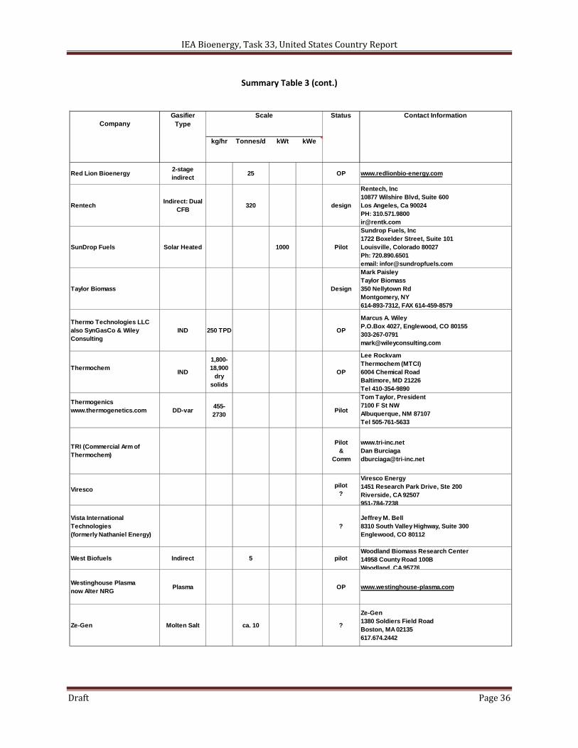
IEA Bioenergy, Task 33, United States Country Report
Draft Page 36
Summary Table 3 (cont.)
CompanyGasifier
TypeStatus Contact Information
kg/hr Tonnes/d kWt kWe
Red Lion Bioenergy2-stage indirect
25 OP www.redlionbio-energy.com
RentechIndirect: Dual
CFB320 design
Rentech, Inc10877 Wilshire Blvd, Suite 600Los Angeles, Ca 90024PH: [email protected]
SunDrop Fuels Solar Heated 1000 Pilot
Sundrop Fuels, Inc1722 Boxelder Street, Suite 101Louisville, Colorado 80027Ph: 720.890.6501email: [email protected]
Taylor Biomass Design
Mark PaisleyTaylor Biomass350 Nellytown RdMontgomery, NY614-893-7312, FAX 614-459-8579
Thermo Technologies LLCalso SynGasCo & Wiley Consulting
IND 250 TPD OP
Marcus A. WileyP.O.Box 4027, Englewood, CO [email protected]
ThermochemIND
1,800-18,900
dry solids
OP
Lee RockvamThermochem (MTCI)6004 Chemical RoadBaltimore, MD 21226Tel 410-354-9890
Thermogenicswww.thermogenetics.com DD-var
455-2730
Pilot
Tom Taylor, President7100 F St NWAlbuquerque, NM 87107Tel 505-761-5633
TRI (Commercial Arm of Thermochem)
Pilot&
Comm
www.tri-inc.netDan [email protected]
Virescopilot
?
Viresco Energy1451 Research Park Drive, Ste 200Riverside, CA 92507951-784-7238
Vista International Technologies(formerly Nathaniel Energy)
?Jeffrey M. Bell8310 South Valley Highway, Suite 300Englewood, CO 80112
West Biofuels Indirect 5 pilotWoodland Biomass Research Center14958 County Road 100BWoodland, CA 95776
Westinghouse Plasmanow Alter NRG
Plasma OP www.westinghouse-plasma.com
Ze-Gen Molten Salt ca. 10 ?
Ze-Gen1380 Soldiers Field RoadBoston, MA 02135617.674.2442
Scale
IEA Bioenergy, Task 33, United States Country Report
Draft Page 37
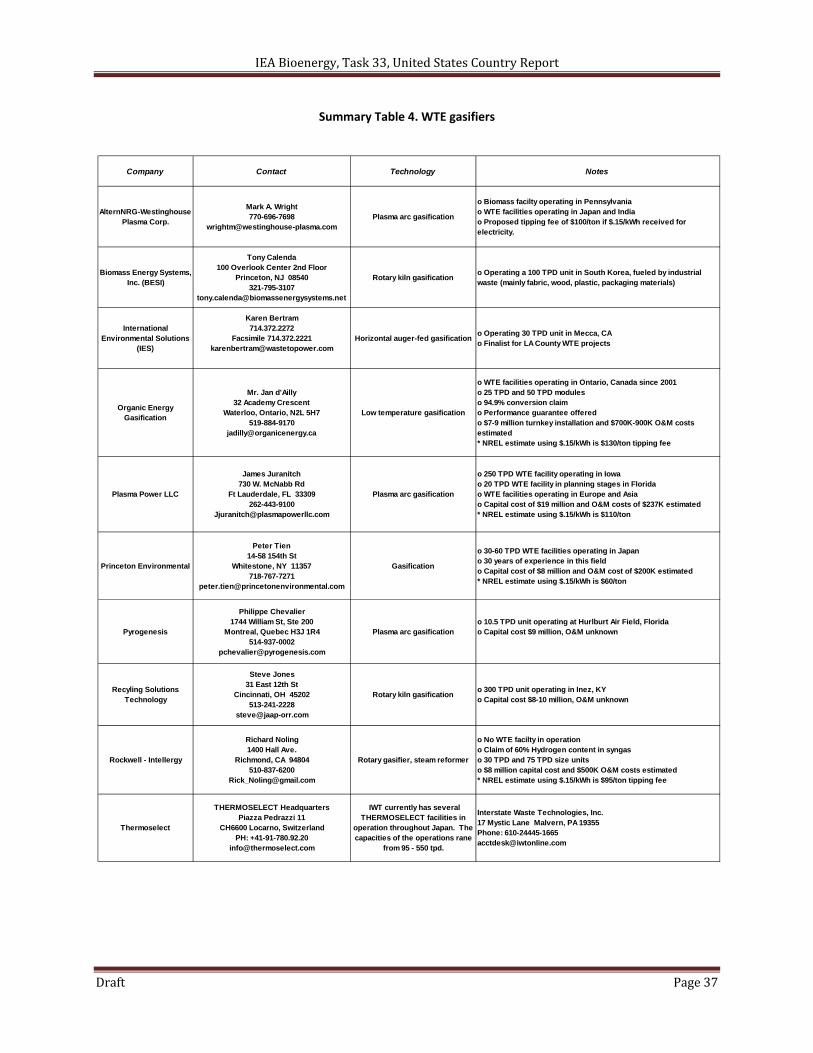
Summary Table 4. WTE gasifiers
Company Contact Technology Notes
AlternNRG-Westinghouse Plasma Corp.
Mark A. Wright770-696-7698
[email protected] arc gasification
o Biomass facilty operating in Pennsylvaniao WTE facilities operating in Japan and Indiao Proposed tipping fee of $100/ton if $.15/kWh received for electricity.
Biomass Energy Systems, Inc. (BESI)
Tony Calenda100 Overlook Center 2nd Floor
Princeton, NJ 08540321-795-3107
Rotary kiln gasificationo Operating a 100 TPD unit in South Korea, fueled by industrial waste (mainly fabric, wood, plastic, packaging materials)
International Environmental Solutions
(IES)
Karen Bertram714.372.2272
Facsimile [email protected]
Horizontal auger-fed gasificationo Operating 30 TPD unit in Mecca, CAo Finalist for LA County WTE projects
Organic Energy Gasification
Mr. Jan d'Ailly32 Academy Crescent
Waterloo, Ontario, N2L 5H7519-884-9170
Low temperature gasification
o WTE facilities operating in Ontario, Canada since 2001o 25 TPD and 50 TPD moduleso 94.9% conversion claimo Performance guarantee offeredo $7-9 million turnkey installation and $700K-900K O&M costs estimated* NREL estimate using $.15/kWh is $130/ton tipping fee
Plasma Power LLC
James Juranitch730 W. McNabb Rd
Ft Lauderdale, FL 33309262-443-9100
Plasma arc gasification
o 250 TPD WTE facility operating in Iowao 20 TPD WTE facility in planning stages in Floridao WTE facilities operating in Europe and Asiao Capital cost of $19 million and O&M costs of $237K estimated* NREL estimate using $.15/kWh is $110/ton
Princeton Environmental
Peter Tien14-58 154th St
Whitestone, NY 11357718-767-7271
Gasification
o 30-60 TPD WTE facilities operating in Japano 30 years of experience in this fieldo Capital cost of $8 million and O&M cost of $200K estimated* NREL estimate using $.15/kWh is $60/ton
Pyrogenesis
Philippe Chevalier1744 William St, Ste 200
Montreal, Quebec H3J 1R4514-937-0002
Plasma arc gasificationo 10.5 TPD unit operating at Hurlburt Air Field, Floridao Capital cost $9 million, O&M unknown
Recyling Solutions Technology
Steve Jones31 East 12th St
Cincinnati, OH 45202513-241-2228
Rotary kiln gasificationo 300 TPD unit operating in Inez, KYo Capital cost $8-10 million, O&M unknown
Rockwell - Intellergy
Richard Noling1400 Hall Ave.
Richmond, CA 94804510-837-6200
Rotary gasifier, steam reformer
o No WTE facilty in operationo Claim of 60% Hydrogen content in syngaso 30 TPD and 75 TPD size unitso $8 million capital cost and $500K O&M costs estimated* NREL estimate using $.15/kWh is $95/ton tipping fee
Thermoselect
THERMOSELECT HeadquartersPiazza Pedrazzi 11
CH6600 Locarno, SwitzerlandPH: +41-91-780.92.20
IWT currently has several THERMOSELECT facilities in
operation throughout Japan. The capacities of the operations rane
from 95 - 550 tpd.
Interstate Waste Technologies, Inc. 17 Mystic Lane Malvern, PA 19355 Phone: [email protected]

IEA Bioenergy, Task 33, United States Country Report
Draft Page 38
STATUS OF SELECTED GASIFIERS WITH PROJECTS IN U.S.
IEA Bioenergy, Task 33, United States Country Report
Draft Page 39
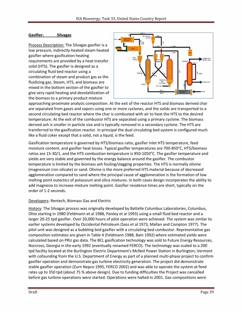
Gasifier: Silvagas
Process Description: The Silvagas gasifier is a low pressure, indirectly‐heated steam heated gasifier where gasification heating requirements are provided by a heat transfer solid (HTS). The gasifier is designed as a circulating fluid bed reactor using a combination of steam and product gas as the fluidizing gas. Steam, HTS, and biomass are mixed in the bottom section of the gasifier to give very rapid heating and devolatilization of the biomass to a primary product mixture approaching proximate analysis composition. At the exit of the reactor HTS and biomass derived char are separated from gases and vapors using one or more cyclones, and the solids are transported to a second circulating bed reactor where the char is combusted with air to heat the HTS to the desired temperature. At the exit of the combustor HTS are separated using a primary cyclone. The biomass derived ash is smaller in particle size and is typically removed in a secondary cyclone. The HTS are transferred to the gasification reactor. In principal the dual circulating bed system is configured much like a fluid coker except that a solid, not a liquid, is the feed.
Gasification temperature is governed by HTS/biomass ratio, gasifier inlet HTS temperature, feed moisture content, and gasifier heat losses. Typical gasifier temperatures are 700‐850°C, HTS/biomass ratios are 15‐30/1, and the HTS combustion temperature is 950‐1050°C. The gasifier temperature and yields are very stable and governed by the energy balance around the gasifier. The combustor temperature is limited by the biomass ash fouling/slagging properties. The HTS is normally olivine (magnesium iron silicate) or sand. Olivine is the more preferred HTS material because of decreased agglomeration compared to sand where the principal cause of agglomeration is the formation of low melting point eutectics of potassium and silica mixtures. In both cases design incorporates the ability to add magnesia to increase mixture melting point. Gasifier residence times are short, typically on the order of 1‐2 seconds.
Developers: Rentech, Biomass Gas and Electric
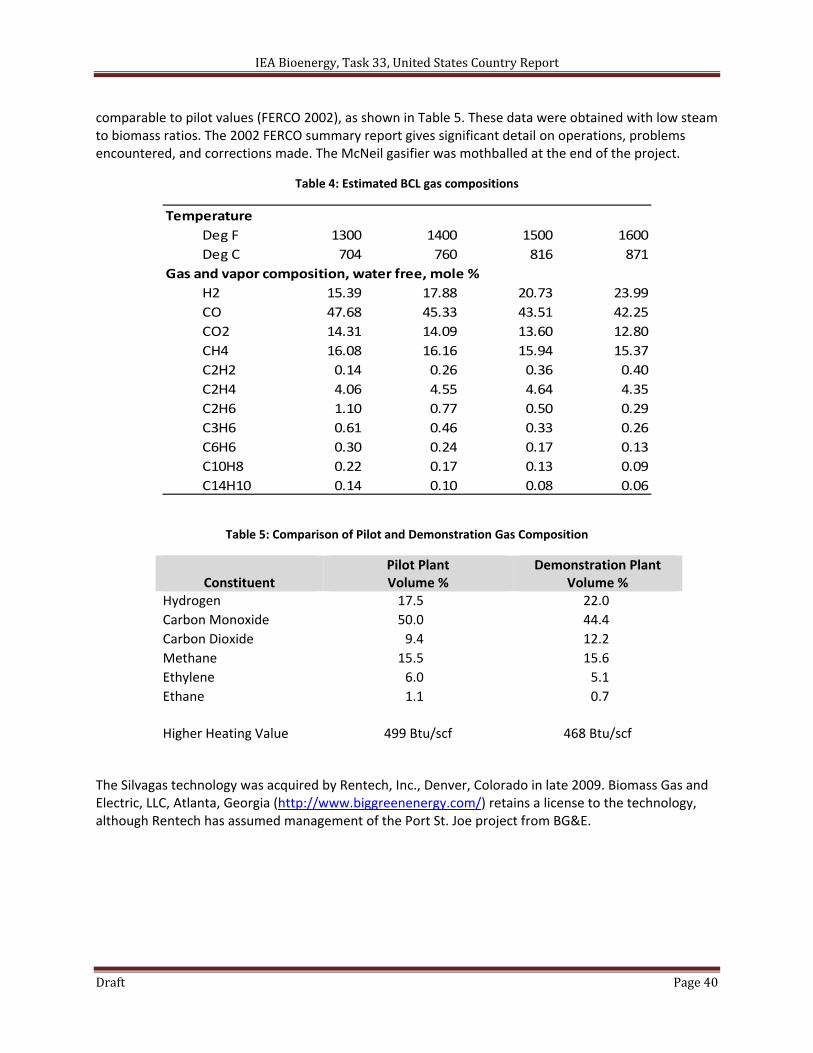
History: The Silvagas process was originally developed by Battelle Columbus Laboratories, Columbus, Ohio starting in 1980 (Feldmann et al 1988, Paisley et al 1993) using a small fluid bed reactor and a larger 20‐25 tpd gasifier. Over 20,000 hours of pilot operation were achieved. The system was similar to earlier systems developed by Occidental Petroleum (Sass et al 1973, Mallan and Compton 1977). The pilot unit was designed as a bubbling bed gasifier with a circulating bed combustor. Representative gas composition estimates are given in Table 4 (Feldmann 1988, Bain 1992) where estimated yields were calculated based on PRU gas data. The BCL gasification technology was sold to Future Energy Resources, Norcross, Georgia in the early 1992 (eventually renamed FERCO). The technology was scaled to a 200 tpd facility located at the Burlington Electric Department's McNeil Power Station in Burlington, Vermont with cofounding from the U.S. Department of Energy as part of a planned multi‐phase project to confirm gasifier operation and demonstrate gas turbine electricity generation. The project did demonstrate stable gasifier operation (Zurn Nepco 1995, FERCO 2002) and was able to operate the system at feed rates up to 350 tpd (about 75 % above design). Due to funding difficulties the Project was cancelled before gas turbine operations were started. Operations were halted in 2001. Gas compositions were
IEA Bioenergy, Task 33, United States Country Report
Draft Page 40
comparable to pilot values (FERCO 2002), as shown in Table 5. These data were obtained with low steam to biomass ratios. The 2002 FERCO summary report gives significant detail on operations, problems encountered, and corrections made. The McNeil gasifier was mothballed at the end of the project.
Table 4: Estimated BCL gas compositions
Temperature
Deg F 1300 1400 1500 1600
Deg C 704 760 816 871
Gas and vapor composition, water free, mole %
H2 15.39 17.88 20.73 23.99
CO 47.68 45.33 43.51 42.25
CO2 14.31 14.09 13.60 12.80
CH4 16.08 16.16 15.94 15.37
C2H2 0.14 0.26 0.36 0.40
C2H4 4.06 4.55 4.64 4.35
C2H6 1.10 0.77 0.50 0.29
C3H6 0.61 0.46 0.33 0.26
C6H6 0.30 0.24 0.17 0.13
C10H8 0.22 0.17 0.13 0.09
C14H10 0.14 0.10 0.08 0.06
Table 5: Comparison of Pilot and Demonstration Gas Composition
Constituent
Pilot Plant Volume %
Demonstration Plant Volume %
Hydrogen 17.5 22.0
Carbon Monoxide 50.0 44.4
Carbon Dioxide 9.4 12.2
Methane 15.5 15.6
Ethylene 6.0 5.1
Ethane 1.1 0.7
Higher Heating Value 499 Btu/scf 468 Btu/scf
The Silvagas technology was acquired by Rentech, Inc., Denver, Colorado in late 2009. Biomass Gas and Electric, LLC, Atlanta, Georgia (http://www.biggreenenergy.com/) retains a license to the technology, although Rentech has assumed management of the Port St. Joe project from BG&E.
IEA Bioenergy, Task 33, United States Country Report
Draft Page 41
General Specifications:
Gasifier type Indirectly‐heated dual circulating fluid bed
Typical Operating Temperature 700‐850°C
Typical Pressure 1 bar
Typical Feed Preparation Cleaning, 5 cm minus, screening, drying to 20 % moisture
Feed Introduction Lock hoppers & rotary valves, screw feeder
Gas cleanup 1st generation– cyclones, gas quench scrubber
Advanced – cyclones, catalytic tar removal, quench
Status: There have been no operating units since the Vermont plant was mothballed.
Installations: The mothballed Vermont plant is the only system.
Projects: Rentech has a number of proposed projects
Project fact sheets can be located at http://www.rentechinc.com/
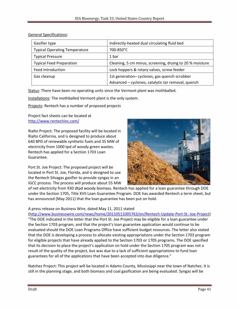
Rialto Project: The proposed facility will be located in Rialto California, and is designed to produce about 640 BPD of renewable synthetic fuels and 35 MW of electricity from 1000 tpd of woody green wastes. Rentech has applied for a Section 1703 Loan Guarantee.
Port St. Joe Project: The proposed project will be located in Port St. Joe, Florida, and is designed to use the Rentech Silvagas gasifier to provide syngas in an IGCC process. The process will produce about 55 MW of net electricity from 930 dtpd woody biomass. Rentech has applied for a loan guarantee through DOE under the Section 1705, Title XVII Loan Guarantee Program. DOE has awarded Rentech a term sheet, but has announced (May 2011) that the loan guarantee has been put on hold.
A press release on Business Wire, dated May 11, 2011 stated (http://www.businesswire.com/news/home/20110511005763/en/Rentech‐Update‐Port‐St.‐Joe‐Project) "The DOE indicated in the letter that the Port St. Joe Project may be eligible for a loan guarantee under the Section 1703 program, and that the project’s loan guarantee application would continue to be evaluated should the DOE Loan Programs Office have sufficient budget resources. The letter also stated that the DOE is developing a process to allocate existing appropriations under the Section 1703 program for eligible projects that have already applied to the Section 1703 or 1705 programs. The DOE specified that its decision to place the project’s application on hold under the Section 1705 program was not a result of the quality of the project, but was due to a lack of sufficient appropriations to fund loan guarantees for all of the applications that have been accepted into due diligence."
Natchez Project: This project will be located in Adams County, Mississippi near the town of Natchez. It is still in the planning stage, and both biomass and coal gasification are being evaluated. Syngas will be
IEA Bioenergy, Task 33, United States Country Report
Draft Page 42
used as feed to Rentech's proprietary Fischer‐Tropsch synthesis technology to produce synthetic fuels and chemicals, as well as producing CO2 for enhanced oil recovery.
Contacts:
Rentech, Inc 10877 Wilshire Blvd, Suite 600 Los Angeles, CA 90024 Ph 310.571.9800 Fax: 310.571.9799 Email: [email protected]
References:
Apanal, G. and H. A. Wright (2010). "System and Method for Dual Fluidized Bed Gasification," United State Patent Application, US2010/0181539 A1, Jul. 22.
Bain, R. L. (1992). "Material and energy balances for methanol from biomass using biomass gasifiers," NREL/TP‐510‐17098, National Renewable Energy Laboratory, Golden, CO, January.
Feldmann, H. F., M. Paisley, H. Applebaum, and D. Taylor (1988). "Conversion of forest residues to a methane‐rich gas in a high‐throughput gasifier," Battelle Columbus Laboratories, prepared for Pacific Northwest National Laboratory, PNL‐6570/DE88‐0131138.
Feldmann, H. F. and M. Paisley (1989). "Low inlet velocity high throughput biomass gasifier, United States Patent 4,828,581, May 9.
Future Energy Resources Corporation (2002). "The Vermont gasification project: phase 2 interim report," prepared for the U.S. Department of Energy.
Paisley, M.A., K. Creamer, T. Tewksbury, and D. Taylor (1989). "Gasification of refuse derived fuel in the Battelle high throughput gasification system," Battelle Columbus Laboratories, prepared for the Pacific Northwest National Laboratory, PNL‐6998/UC‐245.
Paisley, M. (1996)."Method for hot gas conditioning," United States Patent 5,494,653, February 27.
Paisley, M. (2003). "Small scale thigh throughput biomass gasification system and method," United States Patent 6,613,111, September 2.
Paisley, M. (2004a). "Integrated biomass gasification and fuel cell system," United States Patent 6,680,137, January 20.
Paisley, M. (2004b). "Biomass gasification system and method," United States Patent 6,808,543, October 26.
Parent, Y. O., K. Magrini, S. Landin and M. Ritland (2011). "Attrition resistant fluidizable reforming catalyst," United States Patent, 7,915,196, March 29.
Paisley, M.A., R. Litt, D. Taylor, T. Tewkbury, D. Hupp, and R. Wood (1993). "Operation and Evaluation of an indirectly heated biomass gasifier," Battelle Columbus Laboratory, prepared for the National Renewable Energy Laboratory.
Paisley, M. A. and R. Overend (??). "Verification of the performance of Future Energy Resources Silvagas biomass gasifier – operating experience in the Vermont gasifier," available from www.fercoenterprises/downloads/Verification.pdf.
Wyman, C.E., R. L. Bain, N.D. Hinman, and D.J. Stevens, (1993) "Ethanol and Methanol from Cellulosic Materials, "Chapter 21 of Renewable Energy: Sources for Fuels and Electricity, ed T.B. Johansson, et al, Island Press
Zurn Nepco (1995). "Vermont gasifier project, Burlington, Vermont, Contract No. 2064," DOE/GO/10032‐T1, available through OSTI.
IEA Bioenergy, Task 33, United States Country Report
Draft Page 43
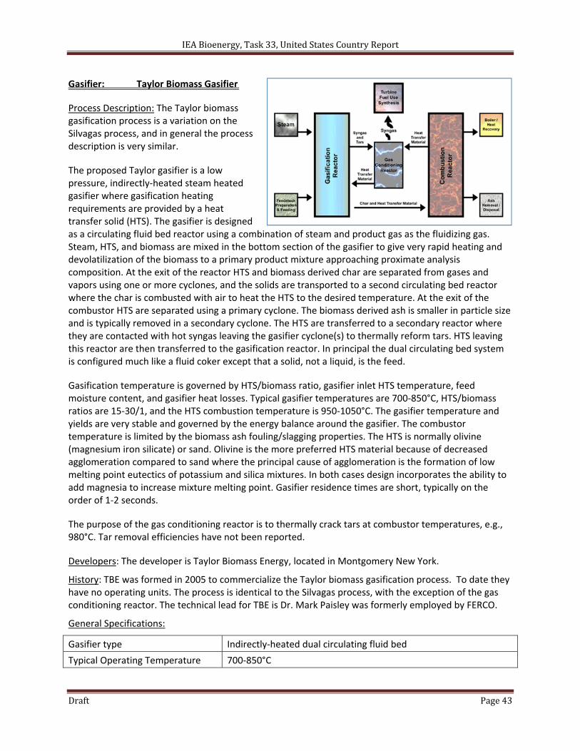
Gasifier: Taylor Biomass Gasifier
Process Description: The Taylor biomass gasification process is a variation on the Silvagas process, and in general the process description is very similar.
The proposed Taylor gasifier is a low pressure, indirectly‐heated steam heated gasifier where gasification heating requirements are provided by a heat transfer solid (HTS). The gasifier is designed as a circulating fluid bed reactor using a combination of steam and product gas as the fluidizing gas. Steam, HTS, and biomass are mixed in the bottom section of the gasifier to give very rapid heating and devolatilization of the biomass to a primary product mixture approaching proximate analysis composition. At the exit of the reactor HTS and biomass derived char are separated from gases and vapors using one or more cyclones, and the solids are transported to a second circulating bed reactor where the char is combusted with air to heat the HTS to the desired temperature. At the exit of the combustor HTS are separated using a primary cyclone. The biomass derived ash is smaller in particle size and is typically removed in a secondary cyclone. The HTS are transferred to a secondary reactor where they are contacted with hot syngas leaving the gasifier cyclone(s) to thermally reform tars. HTS leaving this reactor are then transferred to the gasification reactor. In principal the dual circulating bed system is configured much like a fluid coker except that a solid, not a liquid, is the feed.
Gasification temperature is governed by HTS/biomass ratio, gasifier inlet HTS temperature, feed moisture content, and gasifier heat losses. Typical gasifier temperatures are 700‐850°C, HTS/biomass ratios are 15‐30/1, and the HTS combustion temperature is 950‐1050°C. The gasifier temperature and yields are very stable and governed by the energy balance around the gasifier. The combustor temperature is limited by the biomass ash fouling/slagging properties. The HTS is normally olivine (magnesium iron silicate) or sand. Olivine is the more preferred HTS material because of decreased agglomeration compared to sand where the principal cause of agglomeration is the formation of low melting point eutectics of potassium and silica mixtures. In both cases design incorporates the ability to add magnesia to increase mixture melting point. Gasifier residence times are short, typically on the order of 1‐2 seconds.
The purpose of the gas conditioning reactor is to thermally crack tars at combustor temperatures, e.g., 980°C. Tar removal efficiencies have not been reported.
Developers: The developer is Taylor Biomass Energy, located in Montgomery New York.
History: TBE was formed in 2005 to commercialize the Taylor biomass gasification process. To date they have no operating units. The process is identical to the Silvagas process, with the exception of the gas conditioning reactor. The technical lead for TBE is Dr. Mark Paisley was formerly employed by FERCO.
General Specifications:
Gasifier type Indirectly‐heated dual circulating fluid bed
Typical Operating Temperature 700‐850°C
IEA Bioenergy, Task 33, United States Country Report
Draft Page 44
Typical Pressure 1 bar
Typical Feed Preparation Cleaning, 5 cm minus, screening, drying to 20 % moisture
Feed Introduction Lock hoppers & rotary valves, screw feeder
Gas cleanup cyclones, thermal tar cracker, gas quench scrubber
Status: there are no operating systems.
Installations: There are no existing installations.
Projects: TBE has announced a 1st generation gasification project at its Montgomery, NY facility to produce 20 MW electricity from C&D waste, wood waste, and MSW. Groundbreaking has taken place, and site preparation is underway. TBE has applied for a DOE loan guarantee.
Contacts:
Corporate Taylor Biomass Energy, LLC 336 Neelytown Road Montgomery, NY 12549 Ph: 845.457.4021 http:/www.taylorbiomassenergy.com/
James W. Taylor, President [email protected] Ph: 845.457.4021 x226
Mark Paisley, VP Research & Development [email protected] Ph: 614.893.7312
References:
Paisley, M. (2007). "Advanced biomass gasification for the production of biopower, fuels, and chemicals," AICHE 2007 Annual Meeting, Salt Lake City, Utah, November 5‐9.
Paisley (2008). "Process and system for gasification with in‐situ tar removal," United State Patent Application 20080244976.
IEA Bioenergy, Task 33, United States Country Report
Draft Page 45
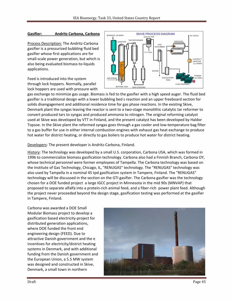
Gasifier: Andritz Carbona, Carbona
Process Description: The Andritz‐Carbona gasifier is a pressurized bubbling fluid bed gasifier whose first applications are for small‐scale power generation, but which is also being evaluated biomass‐to‐liquids applications.
Feed is introduced into the system through lock hoppers. Normally, parallel lock hoppers are used with pressure with gas exchange to minimize gas usage. Biomass is fed to the gasifier with a high speed auger. The fluid bed gasifier is a traditional design with a lower bubbling bed s reaction and an upper freeboard section for solids disengagement and additional residence time for gas phase reactions. In the existing Skive, Denmark plant the syngas leaving the reactor is sent to a two‐stage monolithic catalytic tar reformer to convert produced tars to syngas and produced ammonia to nitrogen. The original reforming catalyst used at Skive was developed by VTT in Finland, and the present catalyst has been developed by Haldor Topsoe. In the Skive plant the reformed syngas goes through a gas cooler and low‐temperature bag filter to a gas buffer for use in either internal combustion engines with exhaust gas heat exchange to produce hot water for district heating, or directly to gas boilers to produce hot water for district heating.
Developers: The present developer is Andritz‐Carbona, Finland.
History: The technology was developed by a small U.S. corporation, Carbona USA, which was formed in 1996 to commercialize biomass gasification technology. Carbona also had a Finnish Branch, Carbona OY, whose technical personnel were former employees of Tampella. The Carbona technology was based on the Institute of Gas Technology, Chicago, IL, "RENUGAS" technology. The "RENUGAS" technology was also used by Tampella in a nominal 45 tpd gasification system in Tampere, Finland. The "RENUGAS" technology will be discussed in the section on the GTI gasifier. The Carbona gasifier was the technology chosen for a DOE funded project a large IGCC project in Minnesota in the mid 90s (MNVAP) that proposed to separate alfalfa into a protein‐rich animal feed, and a fiber‐rich power plant feed. Although the project never proceeded beyond the design stage, gasification testing was performed at the gasifier in Tampere, Finland.
Carbona was awarded a DOE Small Modular Biomass project to develop a gasification based electricity‐project for distributed generation applications, where DOE funded the front end engineering design (FEED). Due to attractive Danish government and the e incentives for electricity/district heating systems in Denmark, and with additional funding from the Danish government and the European Union, a 5.5 MW system was designed and constructed in Skive, Denmark, a small town in northern
SKIVE PROCESS DIAGRAM
DISTRICT HEATING11.5 MWth
POWER3x2 MWe
GAS FILTER
3 GAS ENGINES
BIOMASS, 28 MWth
FLY ASH
2 BOILERS
TO STACK
WATER
GAS SCRUBBER
GAS BUFFERTANK
2x10 MWth
BOTTOM ASH
AIR/STEAM
TAR REFORMERGASIFIER
GAS COOLERS
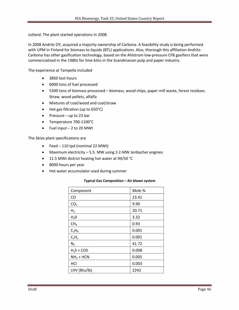
IEA Bioenergy, Task 33, United States Country Report
Draft Page 46
Jutland. The plant started operations in 2008.
In 2008 Andritz OY, acquired a majority ownership of Carbona. A feasibility study is being performed with UPM in Finland for biomass to liquids (BTL) applications. Also, thorough this affiliation Andritz‐Carbona has other gasification technology, based on the Ahlstrom low‐pressure CFB gasifiers that were commercialized in the 1980s for lime kilns in the Scandinavian pulp and paper industry.
The experience at Tampella included
3850 test hours
6000 tons of fuel processed
5300 tons of biomass processed – biomass, wood chips, paper mill waste, forest residues.
Straw, wood pellets, alfalfa
Mixtures of coal/wood and coal/straw
Hot gas filtration (up to 650°C)
Pressure – up to 23 bar
Temperature 700‐1100°C
Fuel input – 2 to 20 MWt
The Skive plant specifications are
Feed – 110 tpd (nominal 22 MWt)
Maximum electricity – 5.5. MW using 3 2‐MW Jenbacher engines
11.5 MWt district heating hot water at 94/50 °C
8000 hours per year
Hot water accumulator used during summer
Typical Gas Composition – Air blown system
Component Mole %
CO 23.41
CO2 9.90
H2 20.71
H20 3.32
CH4 0.93
C2H4 0.001
CxHy 0.001
N2 41.72
H2S + COS 0.008
NH3 + HCN 0.005
HCl 0.003
LHV (Btu/lb) 2242
IEA Bioenergy, Task 33, United States Country Report
Draft Page 47
General Specifications:
Gasifier type Pressurized bubbling fluid bed
Typical Operating Temperature 800‐900°C
Typical Pressure 2‐10 bar
Typical Feed Preparation Pellets, wood chips
Feed Introduction Lock hoppers
Gas cleanup Catalytic tar reforming, gas cooling, filtration, AGR (for BTL)
Status: Andritz‐Carbona has one operating plant, and has completed a feasibility study for a BTL plant in Finland.
Installations: Andritz‐Carbona has one operating plant in Skive, Denmark. Through agreements with GTI, they also have access to the GTI Flex‐fuel pilot gasifier in Chicago.
Projects: Andritz‐Carbona has one operating plant, and has completed a feasibility study for a BTL plant in Finland.
Contacts:
James Patel, President, Carbona Corporation P.O. Box 7067 Napa, CA 94558 United States of America Business Phone: 707‐553‐9800 Business Fax: 707‐553‐9820 E‐mail: [email protected]
Kari Salo, President, Carbona, Finland Kaupintie 11, FIN‐O0440 Helsinki, Finland Business Phone: +358‐ (0) 9‐540 7150 Mobile Phone: +358‐ (0) 400 730 374 Business Fax: +358‐ (0) 9‐540 71540 E‐mail: [email protected]
References:
Patel, J.G. and J. Konttinen (2010). "Process and apparatus for reforming of heavy and light hydrocarbons from product gas of biomass gasification," United States Patent Application 20100187479, July 29.
Salo, K. (2008). "Biomass gasification applications," Topsoe Catalysis Forum 2008, Copenhagen, Denmark, Aug 21‐22.
Skjolborg (2010). "Optimization of I/S Skive district heating plant," IEA Thermal Gasification of Biomass Workshop, Copenhagen, Denmark, Oct 7.
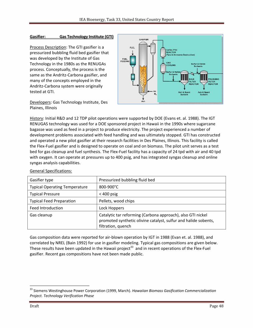
IEA Bioenergy, Task 33, United States Country Report
Draft Page 48
Gasifier: Gas Technology Institute (GTI)
Process Description: The GTI gasifier is a pressurized bubbling fluid bed gasifier that was developed by the Institute of Gas Technology in the 1980s as the RENUGAs process. Conceptually, the process is the same as the Andritz‐Carbona gasifier, and many of the concepts employed in the Andritz‐Carbona system were originally tested at GTI.
Developers: Gas Technology Institute, Des Plaines, Illinois
History: Initial R&D and 12 TDP pilot operations were supported by DOE (Evans et. al. 1988). The IGT RENUGAS technology was used for a DOE sponsored project in Hawaii in the 1990s where sugarcane bagasse was used as feed in a project to produce electricity. The project experienced a number of development problems associated with feed handling and was ultimately stopped. GTI has constructed and operated a new pilot gasifier at their research facilities in Des Plaines, Illinois. This facility is called the Flex‐Fuel gasifier and is designed to operate on coal and on biomass. The pilot unit serves as a test bed for gas cleanup and fuel synthesis. The Flex‐Fuel facility has a capacity of 24 tpd with air and 40 tpd with oxygen. It can operate at pressures up to 400 psig, and has integrated syngas cleanup and online syngas analysis capabilities.
General Specifications:
Gasifier type Pressurized bubbling fluid bed
Typical Operating Temperature 800‐900°C
Typical Pressure < 400 psig
Typical Feed Preparation Pellets, wood chips
Feed Introduction Lock Hoppers
Gas cleanup Catalytic tar reforming (Carbona approach), also GTI nickel promoted synthetic olivine catalyst, sulfur and halide sobents, filtration, quench
Gas composition data were reported for air‐blown operation by IGT in 1988 (Evan et. al. 1988), and correlated by NREL (Bain 1992) for use in gasifier modeling. Typical gas compositions are given below. These results have been updated in the Hawaii project33 and in recent operations of the Flex‐Fuel gasifier. Recent gas compositions have not been made public.
33 Siemens Westinghouse Power Corporation (1999, March). Hawaiian Biomass Gasification Commercialization Project. Technology Verification Phase
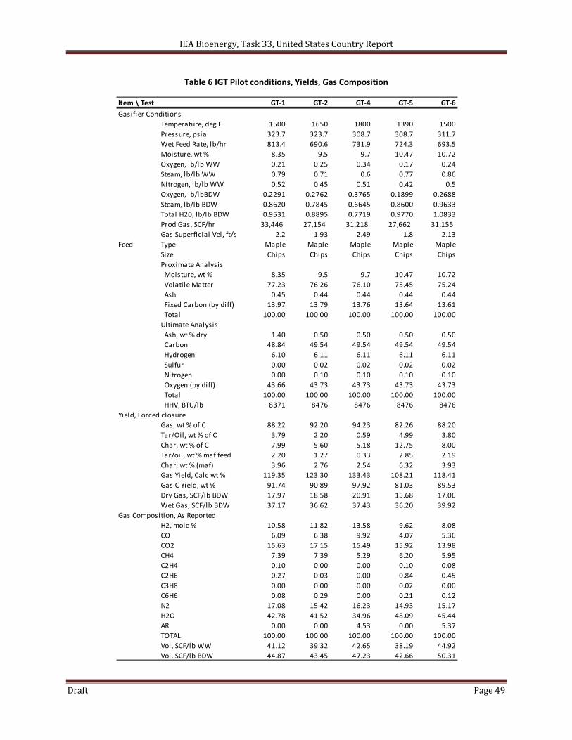
IEA Bioenergy, Task 33, United States Country Report
Draft Page 49
Table 6 IGT Pilot conditions, Yields, Gas Composition
Item \ Test GT‐1 GT‐2 GT‐4 GT‐5 GT‐6
Gasifier Conditions
Temperature, deg F 1500 1650 1800 1390 1500
Pressure, psia 323.7 323.7 308.7 308.7 311.7
Wet Feed Rate, lb/hr 813.4 690.6 731.9 724.3 693.5
Moisture, wt % 8.35 9.5 9.7 10.47 10.72
Oxygen, lb/lb WW 0.21 0.25 0.34 0.17 0.24
Steam, lb/lb WW 0.79 0.71 0.6 0.77 0.86
Nitrogen, lb/lb WW 0.52 0.45 0.51 0.42 0.5
Oxygen, lb/lbBDW 0.2291 0.2762 0.3765 0.1899 0.2688
Steam, lb/lb BDW 0.8620 0.7845 0.6645 0.8600 0.9633
Total H20, lb/lb BDW 0.9531 0.8895 0.7719 0.9770 1.0833
Prod Gas, SCF/hr 33,446 27,154 31,218 27,662 31,155
Gas Superficial Vel, ft/s 2.2 1.93 2.49 1.8 2.13
Feed Type Maple Maple Maple Maple Maple
Size Chips Chips Chips Chips Chips
Proximate Analysis
Moisture, wt % 8.35 9.5 9.7 10.47 10.72
Volatile Matter 77.23 76.26 76.10 75.45 75.24
Ash 0.45 0.44 0.44 0.44 0.44
Fixed Carbon (by diff) 13.97 13.79 13.76 13.64 13.61
Total 100.00 100.00 100.00 100.00 100.00
Ultimate Analysis
Ash, wt % dry 1.40 0.50 0.50 0.50 0.50
Carbon 48.84 49.54 49.54 49.54 49.54
Hydrogen 6.10 6.11 6.11 6.11 6.11
Sulfur 0.00 0.02 0.02 0.02 0.02
Nitrogen 0.00 0.10 0.10 0.10 0.10
Oxygen (by diff) 43.66 43.73 43.73 43.73 43.73
Total 100.00 100.00 100.00 100.00 100.00
HHV, BTU/lb 8371 8476 8476 8476 8476
Yield, Forced closure
Gas, wt % of C 88.22 92.20 94.23 82.26 88.20
Tar/Oil, wt % of C 3.79 2.20 0.59 4.99 3.80
Char, wt % of C 7.99 5.60 5.18 12.75 8.00
Tar/oil, wt % maf feed 2.20 1.27 0.33 2.85 2.19
Char, wt % (maf) 3.96 2.76 2.54 6.32 3.93
Gas Yield, Calc wt % 119.35 123.30 133.43 108.21 118.41
Gas C Yield, wt % 91.74 90.89 97.92 81.03 89.53
Dry Gas, SCF/lb BDW 17.97 18.58 20.91 15.68 17.06
Wet Gas, SCF/lb BDW 37.17 36.62 37.43 36.20 39.92
Gas Composition, As Reported
H2, mole % 10.58 11.82 13.58 9.62 8.08
CO 6.09 6.38 9.92 4.07 5.36
CO2 15.63 17.15 15.49 15.92 13.98
CH4 7.39 7.39 5.29 6.20 5.95
C2H4 0.10 0.00 0.00 0.10 0.08
C2H6 0.27 0.03 0.00 0.84 0.45
C3H8 0.00 0.00 0.00 0.02 0.00
C6H6 0.08 0.29 0.00 0.21 0.12
N2 17.08 15.42 16.23 14.93 15.17
H2O 42.78 41.52 34.96 48.09 45.44
AR 0.00 0.00 4.53 0.00 5.37
TOTAL 100.00 100.00 100.00 100.00 100.00
Vol, SCF/lb WW 41.12 39.32 42.65 38.19 44.92
Vol, SCF/lb BDW 44.87 43.45 47.23 42.66 50.31
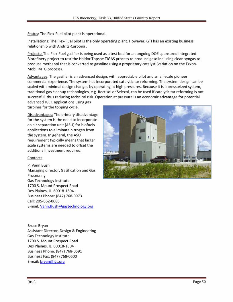
IEA Bioenergy, Task 33, United States Country Report
Draft Page 50
Status: The Flex‐Fuel pilot plant is operational.
Installations: The Flex‐Fuel pilot is the only operating plant. However, GTI has an existing business relationship with Andritz‐Carbona .
Projects: The Flex‐Fuel gasifier is being used as a test bed for an ongoing DOE sponsored Integrated Biorefinery project to test the Haldor Topsoe TIGAS process to produce gasoline using clean syngas to produce methanol that is converted to gasoline using a proprietary catalyst (variation on the Exxon‐Mobil MTG process).
Advantages: The gasifier is an advanced design, with appreciable pilot and small‐scale pioneer commercial experience. The system has incorporated catalytic tar reforming. The system design can be scaled with minimal design changes by operating at high pressures. Because it is a pressurized system, traditional gas cleanup technologies, e.g. Rectisol or Selexol, can be used if catalytic tar reforming is not successful, thus reducing technical risk. Operation at pressure is an economic advantage for potential advanced IGCC applications using gas turbines for the topping cycle.
Disadvantages: The primary disadvantage for the system is the need to incorporate an air separation unit (ASU) for biofuels applications to eliminate nitrogen from the system. In general, the ASU requirement typically means that larger scale systems are needed to offset the additional investment required.
Contacts:
P. Vann Bush Managing director, Gasification and Gas Processing Gas Technology Institute 1700 S. Mount Prospect Road Des Plaines, IL 60018‐1804 Business Phone: (847) 768‐0973 Cell: 205‐862‐0688 E‐mail: [email protected]
Bruce Bryan Assistant Director, Design & Engineering Gas Technology Institute 1700 S. Mount Prospect Road Des Plaines, IL 60018‐1804 Business Phone: (847) 768‐0591 Business Fax: (847) 768‐0600 E‐mail: [email protected]
IEA Bioenergy, Task 33, United States Country Report
Draft Page 51
References:
Bain, R. L. (1992). "Material and energy balances for methanol from biomass using biomass gasifiers," NREL/TP‐510‐17098, National Renewable Energy Laboratory, Golden, CO, January.
Bryan, B.G. V. Bush, R. Slimane, L. Felix and M. Roberts, (2006). "Flex‐Fuel test facility–recent accomplishments and ongoing projects and accomplishments," AIChE–Chicago Symposium, October 9‐10.
Evans, R.J., R. Knight, M. Onischak, S. Babu (1988). " Development of biomass gasification to produce substitute fuels, Institute of Gas Technology for Pacific Northwest National Laboratory, Report PNL_6518, March.
SWPC (Siemens Westinghouse Power Corporation) (1999). "Hawaii biomass gasification commercialization project: technology verification phase final report," prepared for USDOE Golden Field Office, Contract No. DE‐FC36‐96GO10150, March.
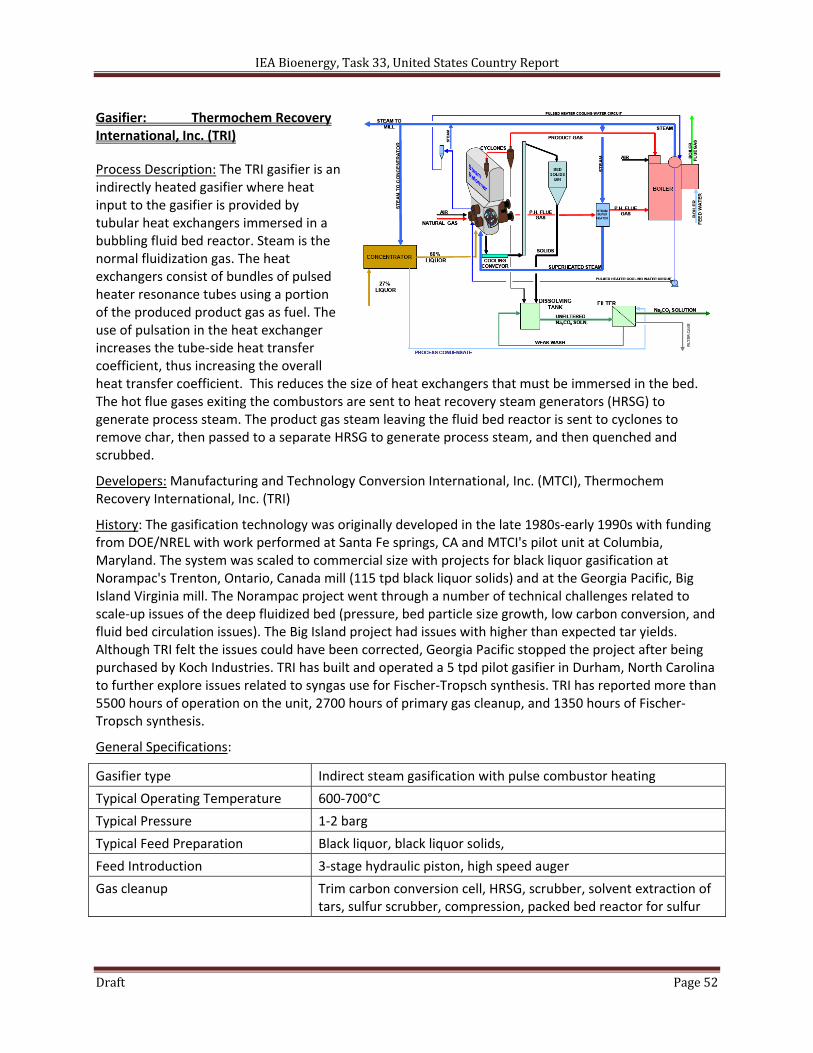
IEA Bioenergy, Task 33, United States Country Report
Draft Page 52
Gasifier: Thermochem Recovery International, Inc. (TRI)
Process Description: The TRI gasifier is an indirectly heated gasifier where heat input to the gasifier is provided by tubular heat exchangers immersed in a bubbling fluid bed reactor. Steam is the normal fluidization gas. The heat exchangers consist of bundles of pulsed heater resonance tubes using a portion of the produced product gas as fuel. The use of pulsation in the heat exchanger increases the tube‐side heat transfer coefficient, thus increasing the overall heat transfer coefficient. This reduces the size of heat exchangers that must be immersed in the bed. The hot flue gases exiting the combustors are sent to heat recovery steam generators (HRSG) to generate process steam. The product gas steam leaving the fluid bed reactor is sent to cyclones to remove char, then passed to a separate HRSG to generate process steam, and then quenched and scrubbed.
Developers: Manufacturing and Technology Conversion International, Inc. (MTCI), Thermochem Recovery International, Inc. (TRI)
History: The gasification technology was originally developed in the late 1980s‐early 1990s with funding from DOE/NREL with work performed at Santa Fe springs, CA and MTCI's pilot unit at Columbia, Maryland. The system was scaled to commercial size with projects for black liquor gasification at Norampac's Trenton, Ontario, Canada mill (115 tpd black liquor solids) and at the Georgia Pacific, Big Island Virginia mill. The Norampac project went through a number of technical challenges related to scale‐up issues of the deep fluidized bed (pressure, bed particle size growth, low carbon conversion, and fluid bed circulation issues). The Big Island project had issues with higher than expected tar yields. Although TRI felt the issues could have been corrected, Georgia Pacific stopped the project after being purchased by Koch Industries. TRI has built and operated a 5 tpd pilot gasifier in Durham, North Carolina to further explore issues related to syngas use for Fischer‐Tropsch synthesis. TRI has reported more than 5500 hours of operation on the unit, 2700 hours of primary gas cleanup, and 1350 hours of Fischer‐Tropsch synthesis.
General Specifications:
Gasifier type Indirect steam gasification with pulse combustor heating
Typical Operating Temperature 600‐700°C
Typical Pressure 1‐2 barg
Typical Feed Preparation Black liquor, black liquor solids,
Feed Introduction 3‐stage hydraulic piston, high speed auger
Gas cleanup Trim carbon conversion cell, HRSG, scrubber, solvent extraction of tars, sulfur scrubber, compression, packed bed reactor for sulfur
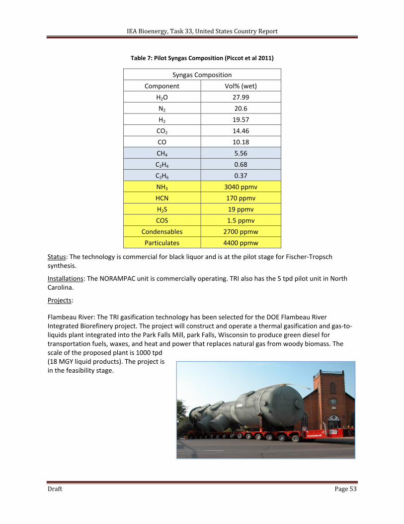
IEA Bioenergy, Task 33, United States Country Report
Draft Page 53
Table 7: Pilot Syngas Composition (Piccot et al 2011)
Syngas Composition
Component Vol% (wet)
H2O 27.99
N2 20.6
H2 19.57
CO2 14.46
CO 10.18
CH4 5.56
C2H4 0.68
C2H6 0.37
NH3 3040 ppmv
HCN 170 ppmv
H2S 19 ppmv
COS 1.5 ppmv
Condensables 2700 ppmw
Particulates 4400 ppmw
Status: The technology is commercial for black liquor and is at the pilot stage for Fischer‐Tropsch synthesis.
Installations: The NORAMPAC unit is commercially operating. TRI also has the 5 tpd pilot unit in North Carolina.
Projects:
Flambeau River: The TRI gasification technology has been selected for the DOE Flambeau River Integrated Biorefinery project. The project will construct and operate a thermal gasification and gas‐to‐liquids plant integrated into the Park Falls Mill, park Falls, Wisconsin to produce green diesel for transportation fuels, waxes, and heat and power that replaces natural gas from woody biomass. The scale of the proposed plant is 1000 tpd (18 MGY liquid products). The project is in the feasibility stage.
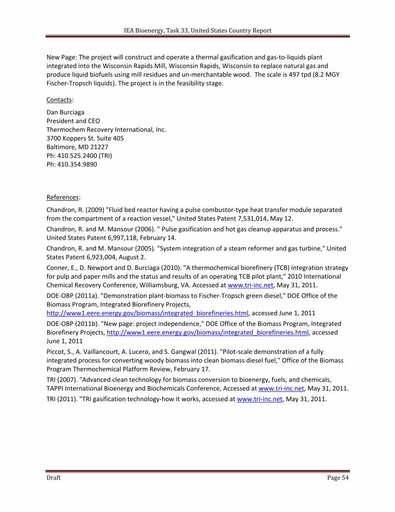
IEA Bioenergy, Task 33, United States Country Report
Draft Page 54
New Page: The project will construct and operate a thermal gasification and gas‐to‐liquids plant integrated into the Wisconsin Rapids Mill, Wisconsin Rapids, Wisconsin to replace natural gas and produce liquid biofuels using mill residues and un‐merchantable wood. The scale is 497 tpd (8.2 MGY Fischer‐Tropsch liquids). The project is in the feasibility stage.
Contacts:
Dan Burciaga President and CEO Thermochem Recovery International, Inc. 3700 Koppers St. Suite 405 Baltimore, MD 21227 Ph: 410.525.2400 (TRI) Ph: 410.354.9890
References:
Chandron, R. (2009) "Fluid bed reactor having a pulse combustor‐type heat transfer module separated from the compartment of a reaction vessel," United States Patent 7,531,014, May 12.
Chandron, R. and M. Mansour (2006). " Pulse gasification and hot gas cleanup apparatus and process." United States Patent 6,997,118, February 14.
Chandron, R. and M. Mansour (2005). "System integration of a steam reformer and gas turbine," United States Patent 6,923,004, August 2.
Conner, E., D. Newport and D. Burciaga (2010). "A thermochemical biorefinery (TCB) integration strategy for pulp and paper mills and the status and results of an operating TCB pilot plant," 2010 International Chemical Recovery Conference, Williamsburg, VA. Accessed at www.tri‐inc.net, May 31, 2011.
DOE‐OBP (2011a). "Demonstration plant‐biomass to Fischer‐Tropsch green diesel," DOE Office of the Biomass Program, Integrated Biorefinery Projects, http://www1.eere.energy.gov/biomass/integrated_biorefineries.html, accessed June 1, 2011
DOE‐OBP (2011b). "New page: project independence," DOE Office of the Biomass Program, Integrated Biorefinery Projects, http://www1.eere.energy.gov/biomass/integrated_biorefineries.html, accessed June 1, 2011
Piccot, S., A. Vaillancourt, A. Lucero, and S. Gangwal (2011). "Pilot‐scale demonstration of a fully integrated process for converting woody biomass into clean biomass diesel fuel," Office of the Biomass Program Thermochemical Platform Review, February 17.
TRI (2007). "Advanced clean technology for biomass conversion to bioenergy, fuels, and chemicals, TAPPI International Bioenergy and Biochemicals Conference, Accessed at www.tri‐inc.net, May 31, 2011.
TRI (2011). "TRI gasification technology‐how it works, accessed at www.tri‐inc.net, May 31, 2011.
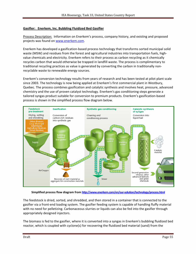
IEA Bioenergy, Task 33, United States Country Report
Draft Page 55
Gasifier: Enerkem, Inc. Bubbling Fluidized Bed Gasifier
Process Description: Information on Enerkem’s process, company history, and existing and proposed projects was found on www.enerkem.com.
Enerkem has developed a gasification‐based process technology that transforms sorted municipal solid waste (MSW) and residues from the forest and agricultural industries into transportation fuels, high‐value chemicals and electricity. Enerkem refers to their process as carbon recycling as it chemically recycles carbon that would otherwise be trapped in landfill waste. The process is complimentary to traditional recycling practices as value is generated by converting the carbon in traditionally non‐recyclable waste to renewable energy sources.
Enerkem’s conversion technology results from years of research and has been tested at pilot plant scale since 2003. The technology is now being applied at Enerkem’s first commercial plant in Westbury, Quebec. The process combines gasification and catalytic synthesis and involves heat, pressure, advanced chemistry and the use of proven catalyst technology. Enerkem's gas conditioning steps generate a tailored syngas product suitable for conversion to premium products. Enerkem’s gasification‐based process is shown in the simplified process flow diagram below.
Simplified process flow diagram from http://www.enerkem.com/en/our‐solution/technology/process.html
The feedstock is dried, sorted, and shredded, and then stored in a container that is connected to the gasifier via a front‐end loading system. The gasifier feeding system is capable of handling fluffy material with no need for pelletizing. Carbonaceous slurries or liquids can also be fed into the gasifier through appropriately designed injectors.
The biomass is fed to the gasifier, where it is converted into a syngas in Enerkem's bubbling fluidized bed reactor, which is coupled with cyclone(s) for recovering the fluidized bed material (sand) from the
IEA Bioenergy, Task 33, United States Country Report
Draft Page 56
syngas. The gasification is accomplished using air or oxygen‐enriched air as a partial oxidation agent. The required level of oxygen‐enrichment is a function of the desired syngas composition. Steam at a controlled partial pressure is also required in the gasification process. The relatively low operating severity of the gasifier, temperatures between 700°C and 750 °C (1,292°F and 1,382°F) and a pressures between 2 atm and 10 atm (30 psia to 147 psia), allows for the use of inexpensive construction materials and refractory.
The syngas from the gasifier is cleaned and conditioned for downstream processes by cyclonic removal of fluidized bed materials, secondary carbon and tar conversion, heat recovery units, and reinjection of tar and solid fines into the gasification reactor. The syngas produced by this process is suitable for conversion to liquid products. Using a sequential catalytic conversion process, the syngas is converted into transportation fuels and chemicals like methanol, ethanol, synthetic gasoline, synthetic diesel, and dimethyl ether.
Developers: Enerkem, Inc.
History: Enerkem manufactures, owns and operates community‐based advanced biorefineries founded on its proprietary thermochemical technology, developed in‐house since the company was founded in 2000. Enerkem is headquartered in Montreal, Canada, and employs over 90 people. It is a private company, majority‐owned by institutional, clean‐technology and industrial investors, including Rho Ventures, Braemar Energy Ventures, Waste Management, Valero Energy, Cycle Capital and BDR Capital. The company has also received financial support from governments and agencies in Canada and in the United States. With the company’s strong in‐house capabilities, Enerkem has full control over its projects and is not dependent on third‐party engineering firms. Current senior management founded the company and continues to hold an ownership stake.
General Specifications:
Gasifier Type Bubbling fluidized‐bed gasifier
Typical Operating Temperature 700°C – 750°C (1,292°F – 1,392°F)
Typical Pressure 2 atm and an 10 atm (30 psia – 150 psia)
Feed Preparation and Introduction
Drying, sorting, shredding.
Loaded to supply hopper by front‐end loading system.
Injected to gasifier through Enerkem’s proprietary feeding system.
Gas Cleanup Cyclonic removal of fluidized bed materials
Secondary carbon and tar conversion
Heat recovery
Reinjection of tar and solid fines to gasifier
Status: Enerkem currently operates two plants in Canada – a pilot facility in Sherbrooke, Quebec and a commercial‐scale plant in Westbury, Quebec. It has recently started the construction of its municipal waste‐to‐biofuels plant in Edmonton, Canada, for which the company has received $23 million from the government of Alberta. Enerkem is also developing a similar project in Mississippi, for which the company was awarded US$50 million in funding by the U.S. Department of Energy (DOE) as well as a conditional commitment for an US$80 million loan guarantee from the U.S. Department of Agriculture (USDA). Additional undisclosed projects are under development in North America and abroad.
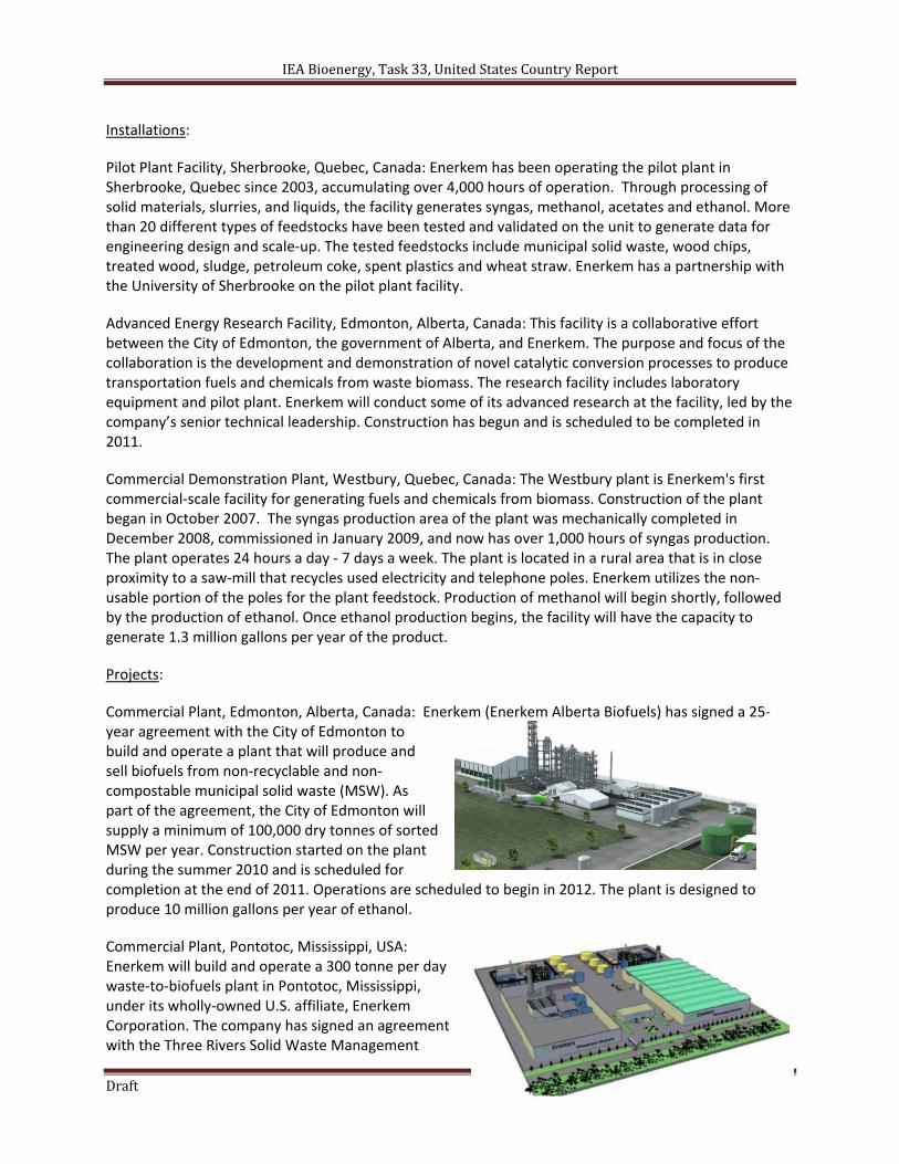
IEA Bioenergy, Task 33, United States Country Report
Draft Page 57
Installations:
Pilot Plant Facility, Sherbrooke, Quebec, Canada: Enerkem has been operating the pilot plant in Sherbrooke, Quebec since 2003, accumulating over 4,000 hours of operation. Through processing of solid materials, slurries, and liquids, the facility generates syngas, methanol, acetates and ethanol. More than 20 different types of feedstocks have been tested and validated on the unit to generate data for engineering design and scale‐up. The tested feedstocks include municipal solid waste, wood chips, treated wood, sludge, petroleum coke, spent plastics and wheat straw. Enerkem has a partnership with the University of Sherbrooke on the pilot plant facility.
Advanced Energy Research Facility, Edmonton, Alberta, Canada: This facility is a collaborative effort between the City of Edmonton, the government of Alberta, and Enerkem. The purpose and focus of the collaboration is the development and demonstration of novel catalytic conversion processes to produce transportation fuels and chemicals from waste biomass. The research facility includes laboratory equipment and pilot plant. Enerkem will conduct some of its advanced research at the facility, led by the company’s senior technical leadership. Construction has begun and is scheduled to be completed in 2011.
Commercial Demonstration Plant, Westbury, Quebec, Canada: The Westbury plant is Enerkem's first commercial‐scale facility for generating fuels and chemicals from biomass. Construction of the plant began in October 2007. The syngas production area of the plant was mechanically completed in December 2008, commissioned in January 2009, and now has over 1,000 hours of syngas production. The plant operates 24 hours a day ‐ 7 days a week. The plant is located in a rural area that is in close proximity to a saw‐mill that recycles used electricity and telephone poles. Enerkem utilizes the non‐usable portion of the poles for the plant feedstock. Production of methanol will begin shortly, followed by the production of ethanol. Once ethanol production begins, the facility will have the capacity to generate 1.3 million gallons per year of the product.
Projects:
Commercial Plant, Edmonton, Alberta, Canada: Enerkem (Enerkem Alberta Biofuels) has signed a 25‐year agreement with the City of Edmonton to build and operate a plant that will produce and sell biofuels from non‐recyclable and non‐compostable municipal solid waste (MSW). As part of the agreement, the City of Edmonton will supply a minimum of 100,000 dry tonnes of sorted MSW per year. Construction started on the plant during the summer 2010 and is scheduled for completion at the end of 2011. Operations are scheduled to begin in 2012. The plant is designed to produce 10 million gallons per year of ethanol.
Commercial Plant, Pontotoc, Mississippi, USA: Enerkem will build and operate a 300 tonne per day waste‐to‐biofuels plant in Pontotoc, Mississippi, under its wholly‐owned U.S. affiliate, Enerkem Corporation. The company has signed an agreement with the Three Rivers Solid Waste Management
IEA Bioenergy, Task 33, United States Country Report
Draft Page 58
Authority of Mississippi (TRSWMA) for the supply of 190,000 tons of unsorted municipal solid waste (MSW) per year. The plant is expected to break ground in 2011. It has successfully met the federal environmental assessment requirements, which allows the company to move forward with the project. Operations are currently scheduled to begin in 2013. The plant is designed to produce 10 million gallons per year of ethanol with plans for future facility expansion that would double the capacity.
Contacts:
Corporate 1010, Sherbrooke street West, Suite 1610 Montreal (Quebec) H3A 2R7, Canada Phone: 514‐875‐0284 Fax: 514‐875‐0835 E‐Mail: [email protected]
Westbury Plant 551 Avenue de la Tuilerie, Westbury (Quebec) J0B 1R0, Canada Phone: 819‐832‐4411 Fax: 819‐832‐3788 E‐Mail: [email protected]
Engineering and Pilot Plant 375 de Courcelette street, Suite 900 Sherbrooke (Quebec) J1H 3X4, Canada Phone: 819‐347‐1111 Fax: 819‐347‐1113 E‐Mail: [email protected]
Edmonton Plant Site 460, 13111 Meridian Street NE Edmonton (Alberta) T6S 1G9, Canada Phone: 819‐347‐1111 Fax : 780‐473‐6418 E‐Mail: [email protected]
Media Marie‐Hélène Labrie Vice President Government Affairs and Communications. E‐Mail: [email protected]
Engineering Denis Arguin Vice President Engineering and Project Implementation E‐Mail: [email protected]
Business Development and Partnerships E‐Mail: [email protected]
References:
Enerkem Company and Technology Information (2011). Retrieved on June 15, 2011 from http://www.enerkem.com/en/home.html
Enerkem (2011). “A Unique Technology: converting waste and residues into advanced fuels and chemicals”. Retrieved on June 15, 2011 from http://www.enerkem.com/assets/files/technologie/enerkems_technology_eng_lr.pdf
Enerkem (2011). “The Carbon Revolution and The Process”. Retrieved on June 15, 2011 from http://www.enerkem.com/assets/files/technologie/Enerkem%20‐%20Process%20in%20more%20details.pdf
U.S. Department of Energy, Energy Efficiency & Renewable Energy, Biomass Program (2010). " Enerkem to use Sorted Waste as Feedstock in Biorefinery". Integrated Biorefinery Factsheet. March 11, 2010. Retrieved on June 15, 2011 from http://www1.eere.energy.gov/biomass/pdfs/ibr_arra_enerkem.pdf
IEA Bioenergy, Task 33, United States Country Report
Draft Page 59
Labrie, Marie‐Helene (2009). “Gasification Technologies: Making Second‐Generation Biofuels a Reality,” Biomass Magazine: 41 – 44. August, 2009. http://biomassmagazine.com/articles/2926/gasification‐technologies‐making‐second‐generation‐biofuels‐a‐reality
Chornet, Esteban; Valsecchi, Boris; Rheault, Sebastien; Gagnon, Martin (2010). Enerkem, Inc. “Production of synthesis gas through controlled oxidation of biomass,” United States Patent Application 20100224835. September 9, 2010.
Chornet, Esteban; Valsecchi, Boris; Drolet, Guillaume; Gagnon, Martin; Nguyen, Betty (2010). Enerkem, Inc. “Production and conditioning of synthesis gas obtained from biomass,” United States Patent Application 20100051875. March 4, 2010.
Chornet, Esteban; Mincic, Aca; Gagnon, Martin; Valsecchi, Boris (2010). Enerkem, Inc. “METHOD FOR LOW‐SEVERITY GASIFICATION OF HEAVY PETROLEUM RESIDUES,” United States Patent Application 20100024300. February 4, 2010.
Chornet, Esteban; Valsecchi, Boris; Avila, Yasmin; Nguyen, Betty; Lavoie, Jean‐Michel (2009). Enerkem, Inc. “Production of ethanol from methanol,” United States Patent Application 20090326080. December 31, 2009.
Chornet, Esteban; Valsecchi, Boris; Avila, Yasmin; Nguyen, Betty; Lavoie, Jean‐Michel (2009). Enerkem, Inc. “Production of ethanol from methanol,” United States Patent Application 20090221725. September 3, 2009.
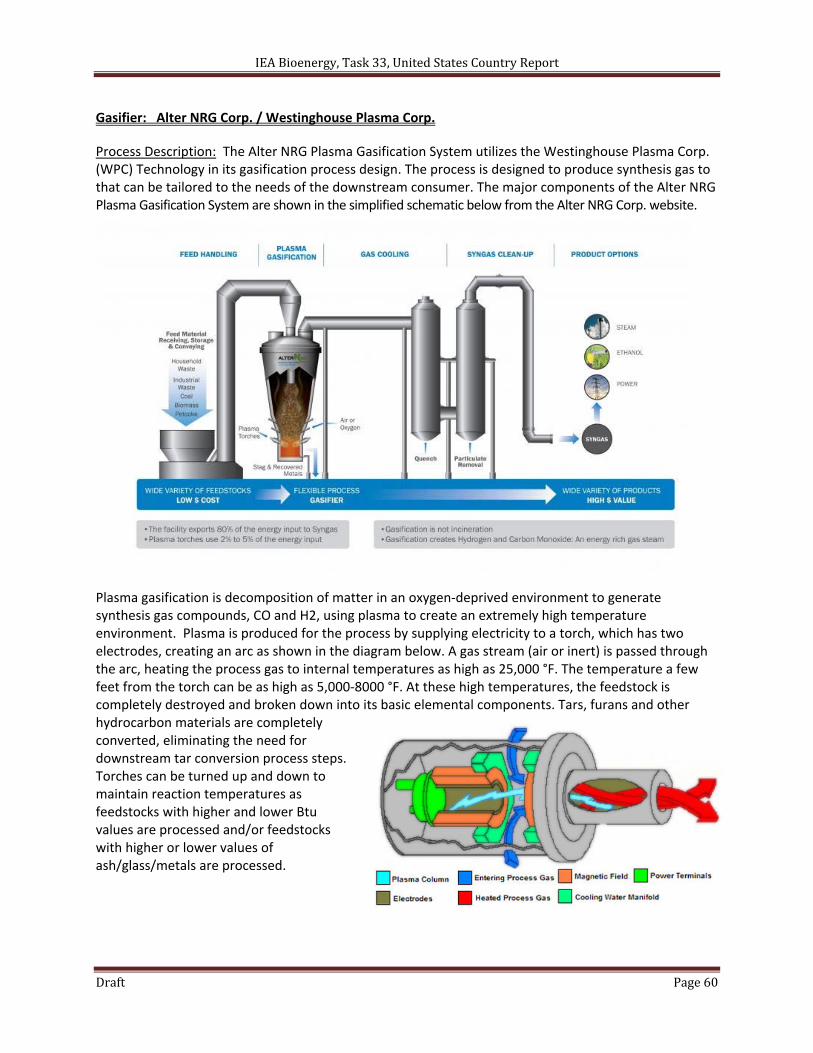
IEA Bioenergy, Task 33, United States Country Report
Draft Page 60
Gasifier: Alter NRG Corp. / Westinghouse Plasma Corp.
Process Description: The Alter NRG Plasma Gasification System utilizes the Westinghouse Plasma Corp. (WPC) Technology in its gasification process design. The process is designed to produce synthesis gas to that can be tailored to the needs of the downstream consumer. The major components of the Alter NRG Plasma Gasification System are shown in the simplified schematic below from the Alter NRG Corp. website.
Plasma gasification is decomposition of matter in an oxygen‐deprived environment to generate synthesis gas compounds, CO and H2, using plasma to create an extremely high temperature environment. Plasma is produced for the process by supplying electricity to a torch, which has two electrodes, creating an arc as shown in the diagram below. A gas stream (air or inert) is passed through the arc, heating the process gas to internal temperatures as high as 25,000 °F. The temperature a few feet from the torch can be as high as 5,000‐8000 °F. At these high temperatures, the feedstock is completely destroyed and broken down into its basic elemental components. Tars, furans and other hydrocarbon materials are completely converted, eliminating the need for downstream tar conversion process steps. Torches can be turned up and down to maintain reaction temperatures as feedstocks with higher and lower Btu values are processed and/or feedstocks with higher or lower values of ash/glass/metals are processed.
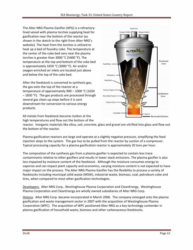
IEA Bioenergy, Task 33, United States Country Report
Draft Page 61
The Alter NRG Plasma Gasifier (APG) is a refractory‐lined vessel with plasma torches supplying heat for gasification near the bottom of the reactor (as shown in the sketch to the right from Alter NRG’s website). The heat from the torches is utilized to heat up a bed of foundry coke. The temperature at the center of the coke bed very near the plasma torches is greater than 3000 °C (5400 °F). The temperature at the top and bottom of the coke bed is approximately 1650 °C (3000 °F). Air and/or oxygen‐enriched air inlets are located just above and below the top of the coke bed.
After the feedstock is converted to synthesis gas, the gas exits the top of the reactor at a temperature of approximately 900 – 1000 °C (1650 – 1830 °F). The gas products are processed through several gas clean‐up steps before it is sent downstream for conversion to various energy products.
All metals from feedstock become molten at the high temperatures and flow out the bottom of the reactor. Inorganic materials like silica, soil, concrete, glass and gravel are vitrified into glass and flow out the bottom of the reactor.
Plasma gasification reactors are large and operate at a slightly negative pressure, simplifying the feed injection steps to the system. The gas has to be pulled from the reactor by suction of a compressor. Typical processing capacity for a plasma gasification reactor is approximately 20 tons per hour.
The composition of the synthesis gas from a plasma gasifier is expected to contain less trace contaminants relative to other gasifiers and results in lower stack emissions. The plasma gasifier is also less impacted by moisture content of the feedstock. Although the moisture consumes energy to vaporize and can impact plant capacity and economics, varying moisture content is not expected to have major impact on the process. The Alter NRG Plasma Gasifier has the flexibility to process a variety of feedstocks including municipal solid waste (MSW), industrial waste, biomass, coal, petroleum coke and tires, when compared to most other gasification technologies.
Developers: Alter NRG Corp., Westinghouse Plasma Corporation and CleanEnergy. Westinghouse Plasma Corporation and CleanEnergy are wholly owned subsidiaries of Alter NRG Corp.
History: Alter NRG Corp. became incorporated in March 2006. The company emerged onto the plasma gasification and waste management sector in 2007 with the acquisition of Westinghouse Plasma Corporation (WPC). The acquisition of WPC positioned Alter NRG as a key technology contender in plasma gasification of household waste, biomass and other carbonaceous feedstocks.
IEA Bioenergy, Task 33, United States Country Report
Draft Page 62
General Specifications:
Gasifier Type High‐temperature plasma gasifier
Typical Operating Temperature Coke bed: 1650 °C (3000 °F) Synthesis gas outlet: 900 – 1000 °C (1650 – 1830 °F)
Typical Pressure Vacuum to atmospheric
Feed Preparation and Introduction
Feed process includes heavy duty shredder and automotive tire cutter (tires represent 5% of feedstock).
Gas Cleanup Quench, particulate and HCl removal by Venturi scrubber Wet electrostatic precipitator (ESP) Mercury removal Syngas compression COS hydrolysis Sulfur removal
Status: The Alter NRG Plasma Gasification technology has been demonstrated commercially in metallurgical and waste‐to‐energy applications at several locations and is currently pursuing other projects.
Installations: Alter NRG Corp. continues to operate a 48 tonne per day commercial demonstration facility in Madison, PA. Alter NRG‐owned Westinghouse Plasma Corp (WPC) plasma torch systems are proven in metallurgical and waste‐to‐energy (WTE) commercial applications. The commercial applications of Alter NRG’s Plasma Gasification process are summarized in the following table.
Customer & Location Application
Hitachi Metals Ltd. Utashinai, Japan ‐ Eco‐Valley Waste‐to‐Energy Facility
Commercial Gasification of Auto Shredder Residue & MSW
Hitachi Metals Ltd. Mihama‐Mikata, Japan
Commercial Gasification of MSW & Waste Water Sludge
Ishkawajima‐Harima Heavy Industries Co. (IHI) Kinuura, Japan
Commercial Vitrification of MSW Incinerator Ash
Aluminum Canada Ltd. (ALCAN) Chicoutimi, Quebec – Canada
Commercial Aluminum Dross Recovery Furnaces
General Motors Corporation Central Foundry Division Defiance, Ohio, U.S.A.
Commercial Cast Iron Production
Projects: The following current project descriptions for Project Lighthouse and SMSIL – India are from the Alter NRG website.
Project Lighthouse: Commercial demonstration facility for ethanol production at Alter NRG’s pilot facility in Madison, PA. Alter NRG and Westinghouse Plasma Corporation (WPC) announced, on April 25, 2008, that the existing Westinghouse Plasma Corporation commercial demonstration facility has been chosen as the site for a cellulosic ethanol commercial demonstration project using Coskata Inc.’s proprietary synthesis gas (syngas) to ethanol conversion technology. This commercial demonstration facility developed by Coskata Inc. (Coskata) uses the Westinghouse Plasma Corporation's (WPC) gasification process as the biomass to synthesis gas conversion process. The construction of this project
IEA Bioenergy, Task 33, United States Country Report
Draft Page 63
was completed in November, 2009. The facility is in operation and represents a significant milestone in the development of cellulosic ethanol from non‐food feedstocks and is expected to lower operating costs compared to current ethanol production.
SMSIL ‐ India: The world's largest plasma gasification facility processing hazardous waste. SMS Envocare Ltd, part of Central India’s largest civil engineering and infrastructure development company, is using the Westinghouse Plasma Gasification plasma technology and reactor vessel design in two 72 tonnes‐per‐day energy recovery from hazardous waste plants. Construction is complete at the first facility in Pune and the plant has been operating for 2 years. SMS also built another 72 tonnes‐per‐day energy recovery from hazardous waste facility in Nagpur. This facility was commissioned Q4 2010. Each plant provides comprehensive disposal services for a wide variety of hazardous waste, and produces up to 1.6 MW (net) of electricity.
Contacts:
Alter NRG Corp. 215, 4000 ‐ 4th Street SE Calgary, Alberta T2G 2W3 Telephone: 403.806.3875 Fax: 403.806.3721 Email: [email protected] Kevin Willerton Vice President, Strategic Alliances & Business Development Email: [email protected]
References:
Dighe, Shyam; Bower, Rick; van Nierop, Pieter; Gorodetsky, Alex (2008). “Alter NRG and Westinghouse Plasma Corp. – The Plasma Gasification Process,” Presented to the Calgary & Region Waste Reduction Partnership. Feb. 13, 2008. http://www.calgaryregion.ca/crp/media/32152/the_alter_NRG_plasma_gasification_process_‐_turner_valley_presentation.ppt.pdf
Alter NRG Plasma Gasification Technology (2011). Retrieved on June 6, 2011 from http://alterNRG.com/plasma_technology/products_and_services/plasma_gasification
What is Plasma Gasification? (2011). Retrieved on June 6, 2011 from http://www.westinghouse‐plasma.com/technology/what‐is‐plasma‐gasification
Waste Technology Reports (2008). “The Alter NRG / Westinghouse Plasma Gasification Process,” Independent Waste Technology Report by Juniper Consultancy Services Limited, Bathurst House, Bisley, GL6 7NH England. November 2008. http://www.enonac.org/documents/issues/sun.energy/juniper.pdf
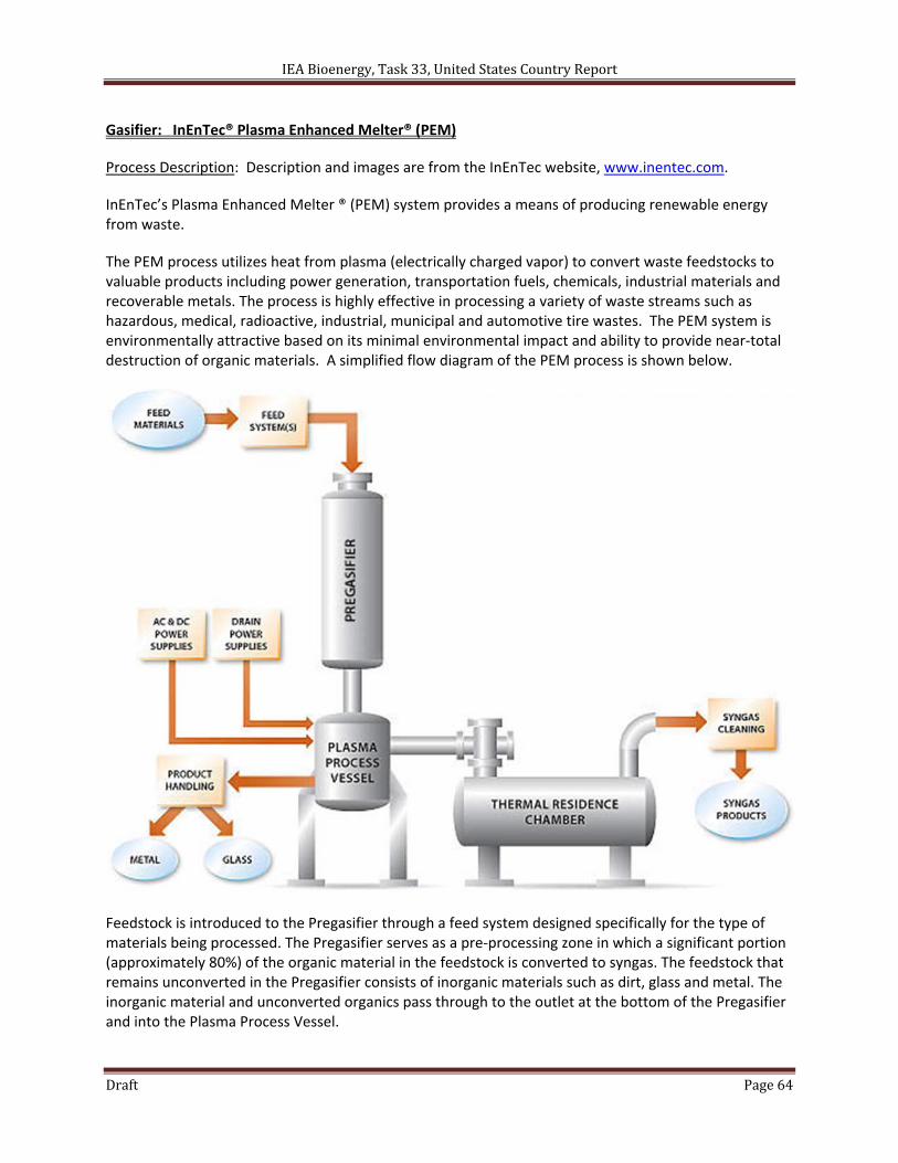
IEA Bioenergy, Task 33, United States Country Report
Draft Page 64
Gasifier: InEnTec® Plasma Enhanced Melter® (PEM)
Process Description: Description and images are from the InEnTec website, www.inentec.com.
InEnTec’s Plasma Enhanced Melter ® (PEM) system provides a means of producing renewable energy from waste.
The PEM process utilizes heat from plasma (electrically charged vapor) to convert waste feedstocks to valuable products including power generation, transportation fuels, chemicals, industrial materials and recoverable metals. The process is highly effective in processing a variety of waste streams such as hazardous, medical, radioactive, industrial, municipal and automotive tire wastes. The PEM system is environmentally attractive based on its minimal environmental impact and ability to provide near‐total destruction of organic materials. A simplified flow diagram of the PEM process is shown below.
Feedstock is introduced to the Pregasifier through a feed system designed specifically for the type of materials being processed. The Pregasifier serves as a pre‐processing zone in which a significant portion (approximately 80%) of the organic material in the feedstock is converted to syngas. The feedstock that remains unconverted in the Pregasifier consists of inorganic materials such as dirt, glass and metal. The inorganic material and unconverted organics pass through to the outlet at the bottom of the Pregasifier and into the Plasma Process Vessel.
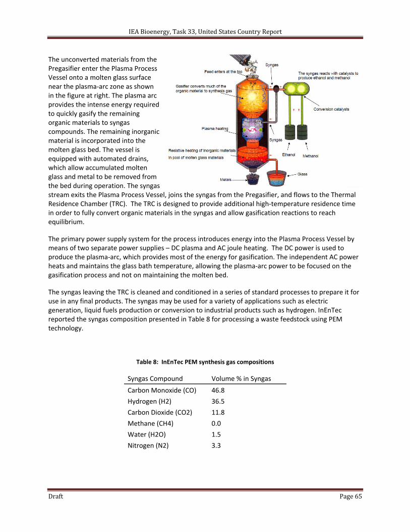
IEA Bioenergy, Task 33, United States Country Report
Draft Page 65
The unconverted materials from the Pregasifier enter the Plasma Process Vessel onto a molten glass surface near the plasma‐arc zone as shown in the figure at right. The plasma arc provides the intense energy required to quickly gasify the remaining organic materials to syngas compounds. The remaining inorganic material is incorporated into the molten glass bed. The vessel is equipped with automated drains, which allow accumulated molten glass and metal to be removed from the bed during operation. The syngas stream exits the Plasma Process Vessel, joins the syngas from the Pregasifier, and flows to the Thermal Residence Chamber (TRC). The TRC is designed to provide additional high‐temperature residence time in order to fully convert organic materials in the syngas and allow gasification reactions to reach equilibrium.
The primary power supply system for the process introduces energy into the Plasma Process Vessel by means of two separate power supplies – DC plasma and AC joule heating. The DC power is used to produce the plasma‐arc, which provides most of the energy for gasification. The independent AC power heats and maintains the glass bath temperature, allowing the plasma‐arc power to be focused on the gasification process and not on maintaining the molten bed.
The syngas leaving the TRC is cleaned and conditioned in a series of standard processes to prepare it for use in any final products. The syngas may be used for a variety of applications such as electric generation, liquid fuels production or conversion to industrial products such as hydrogen. InEnTec reported the syngas composition presented in Table 8 for processing a waste feedstock using PEM technology.
Table 8: InEnTec PEM synthesis gas compositions
Syngas Compound Volume % in Syngas
Carbon Monoxide (CO) 46.8
Hydrogen (H2) 36.5
Carbon Dioxide (CO2) 11.8
Methane (CH4) 0.0
Water (H2O) 1.5
Nitrogen (N2) 3.3
IEA Bioenergy, Task 33, United States Country Report
Draft Page 66
Developers: InEnTec, LLC (Integrated Environmental Technologies, LLC), Richland, WA and Bend, OR.
History: InEnTec’s Plasma Enhanced Melter® (PEM) technology is the result of decades of development work in two areas – plasma technology and glass melter technology. By integrating the technologies, InEnTec created a concept that provides the capability of converting waste into useful and valuable products. The PEM technology builds on extensive U.S. Department of Energy (DOE)‐sponsored research at the Massachusetts Institute of Technology (MIT) and Battelle Pacific Northwest National Laboratory (PNNL).
Plasma applications have been investigated extensively at MIT’s Plasma Science and Fusion Center (PSFC). The PSFC undertook a research program in 1991 to explore plasmas for treatment of radioactive waste at DOE sites. Plasma technology was very attractive relative to other incineration technologies due to the extremely high temperatures and the plasma’s ability to process waste without the adverse environmental impacts. MIT and an industrial subcontractor formed a collaborative alliance with PNNL, which is considered a world leader in waste treatment technology. The MIT ‐ PNNL collaboration constructed a research device at MIT for studies of plasma‐arc waste treatment. The facility was utilized for a variety of tests that confirmed the effectiveness plasma technology for treating radioactive and hazardous waste.
Encouraged by the program’s results, the primary researchers – Dr. Daniel R. Cohn of MIT, Jeffrey E. Surma of PNNL and Charles H. Titus of General Electric Company, began to investigate means of improving the process to make it applicable to other waste types including medical waste, tires, hazardous wastes and municipal waste. The team developed of process concept that integrated the plasma technology with glass melter technology, which had been developed for treatment of radioactive wastes. The integrated design utilized a unique configuration of multiple plasma electrodes for providing radiant heating and other electrodes submerged in a molten glass bath for providing resistive heating to maintain the molten bath. The new design provided optimized electrical heating with exceptional process control. This concept was further developed and became the earliest element of InEnTec’s proprietary PEM process.
The inventors began to look for ways to commercialize the technology, teamed with investor(s), and formed Integrated Environmental Technologies, LLC in July 1995. InEnTec opened its Technology Center in Richland, Washington in 1996. The center houses the company’s technology development efforts, which have led to the commercialization and deployment of the PEM technology around the world. The company changed its name in 2008 to InEnTec LLC and moved its headquarters to Bend, Oregon. On October 14, 2008, InEnTec formed InEnTec Chemical LLC in a joint venture with Lakeside Energy LLC, and on February 9, 2009, InEnTec formed S4 Energy Solutions LLC in a joint venture with Waste Management, Inc.
IEA Bioenergy, Task 33, United States Country Report
Draft Page 67
General Specifications:
Gasifier Type High‐temperature plasma gasifier
Typical Operating Temperature Plasma Process Vessel: 1,100 – 1,300 °C
Thermal Residence Chamber: 700 – 900 °C
Typical Pressure Vacuum (‐2.0 to ‐0.2 inches H2O per EvTec report)
Feed Preparation and Introduction
Continuous screw feeder with airlock hopper for solid feedstocks.
Feed tank and pump for liquid and sludge feedstocks.
Gas Cleanup Syngas cooling
Baghouse particulate removal (1 mm and greater)
Two‐stage Venturi scrubber system
Mist eliminator, syngas reheat and HEPA filter
Status: InEnTec’s PEM process is employed at a number of commercial scale facilities (refer to list of installations below). The company is currently working on two projects for the production of electricity and liquid fuels from waste feedstock. Fulcurm Bioenergy has licensed InEnTec’s PEM technology for converting 250 tons per day of municipal solid waste to ethanol at their Sierra Biofuels Plant outside of Reno, Nevada. S4 Energy Solutions, a joint venture between InEnTec and Waste Management, is constructing a PEM facility at Waste Management’s Columbia Ridge Landfill in Arlington, Oregon to convert municipal solid waste and recovered landfill vapors to power and clean fuels.
Installations: The table below presents a summary of InEnTec’s installed PEM facilities.
Facility Processing Function Status
Dow Corning Midland, MI, USA
Processes industrial byproducts from Dow Corning’s operations and converts to products such as hydrochloric acid and syngas, which are reused in the manufacturing operations.
In startup and shakedown of operations. Commencement of full commercial operation is imminent.
InEnTec Tech Center Richland, WA, USA
The system is used to process portions of the City of Richland’s daily MSW stream and to further commercialize the PEM technology.
Utilized for testing various feedstocks from potential and existing customers.
InEnTec Leasing Services LLC Transportable System
The system began operation for demonstrating processing of MSW in March 2007 at Fort Riley Army Base in Kansas. The syngas produced by the system was used as fuel in a dual‐fuel generator mounted on a second flat bed trailer.
The unit has been moved to process various materials, including debris from tornado and storm activity.
Global Plasma Technology Limited Taipei, Taiwan
Processing medical waste, batteries, spent solvents, lab packs, and mercury vapor lamps. The syngas generated from the process is used in a dual‐fuel generator to produce electricity.
Began operating in March 2005
Kawasaki Plant Systems Harima, Japan
Demonstrated PEM for destruction of asbestos materials for potential clients.
Began operation in April 2006 and concluded in June 2006
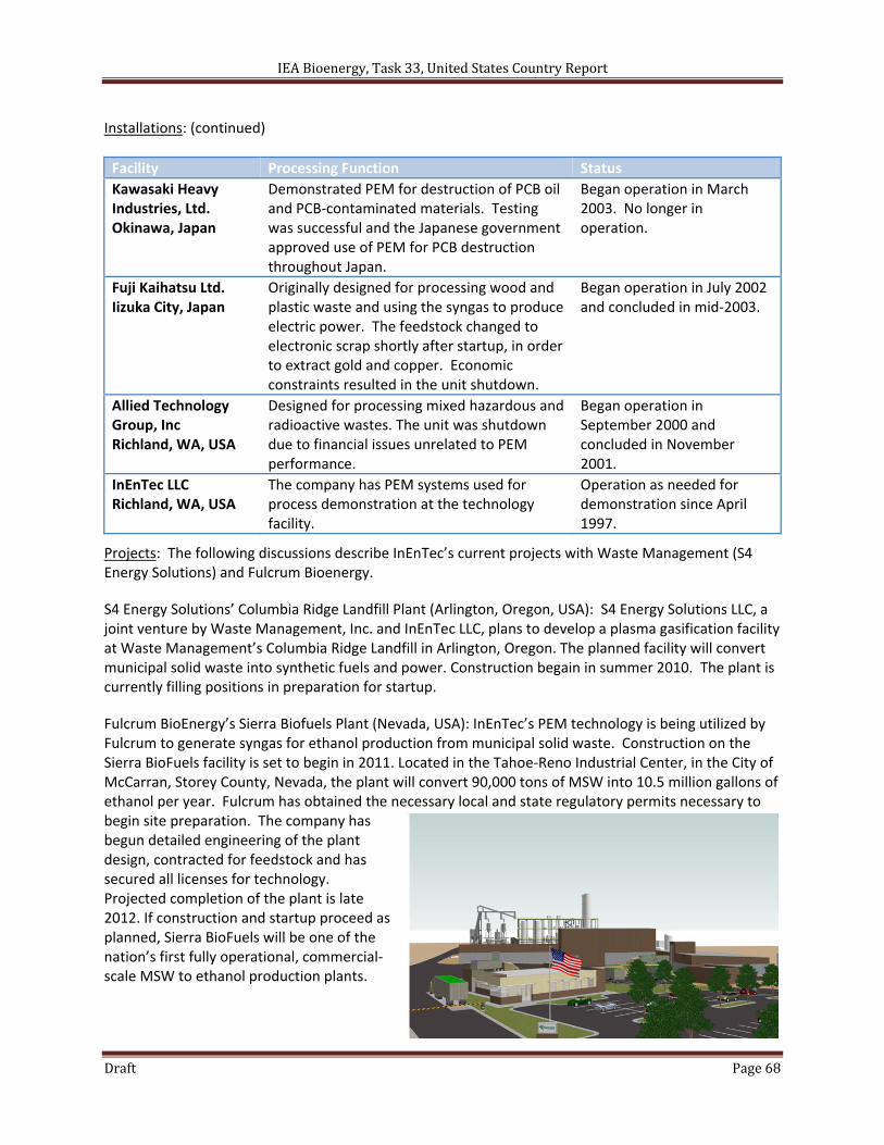
IEA Bioenergy, Task 33, United States Country Report
Draft Page 68
Installations: (continued)
Facility Processing Function Status
Kawasaki Heavy Industries, Ltd. Okinawa, Japan
Demonstrated PEM for destruction of PCB oil and PCB‐contaminated materials. Testing was successful and the Japanese government approved use of PEM for PCB destruction throughout Japan.
Began operation in March 2003. No longer in operation.
Fuji Kaihatsu Ltd. Iizuka City, Japan
Originally designed for processing wood and plastic waste and using the syngas to produce electric power. The feedstock changed to electronic scrap shortly after startup, in order to extract gold and copper. Economic constraints resulted in the unit shutdown.
Began operation in July 2002 and concluded in mid‐2003.
Allied Technology Group, Inc Richland, WA, USA
Designed for processing mixed hazardous and radioactive wastes. The unit was shutdown due to financial issues unrelated to PEM performance.
Began operation in September 2000 and concluded in November 2001.
InEnTec LLC Richland, WA, USA
The company has PEM systems used for process demonstration at the technology facility.
Operation as needed for demonstration since April 1997.
Projects: The following discussions describe InEnTec’s current projects with Waste Management (S4 Energy Solutions) and Fulcrum Bioenergy.
S4 Energy Solutions’ Columbia Ridge Landfill Plant (Arlington, Oregon, USA): S4 Energy Solutions LLC, a joint venture by Waste Management, Inc. and InEnTec LLC, plans to develop a plasma gasification facility at Waste Management’s Columbia Ridge Landfill in Arlington, Oregon. The planned facility will convert municipal solid waste into synthetic fuels and power. Construction begain in summer 2010. The plant is currently filling positions in preparation for startup.
Fulcrum BioEnergy’s Sierra Biofuels Plant (Nevada, USA): InEnTec’s PEM technology is being utilized by Fulcrum to generate syngas for ethanol production from municipal solid waste. Construction on the Sierra BioFuels facility is set to begin in 2011. Located in the Tahoe‐Reno Industrial Center, in the City of McCarran, Storey County, Nevada, the plant will convert 90,000 tons of MSW into 10.5 million gallons of ethanol per year. Fulcrum has obtained the necessary local and state regulatory permits necessary to begin site preparation. The company has begun detailed engineering of the plant design, contracted for feedstock and has secured all licenses for technology. Projected completion of the plant is late 2012. If construction and startup proceed as planned, Sierra BioFuels will be one of the nation’s first fully operational, commercial‐scale MSW to ethanol production plants.
IEA Bioenergy, Task 33, United States Country Report
Draft Page 69
Contacts:
InEnTec Main Office 595 SW Bluff Drive, Suite B Bend, OR 97702
InEnTec Technology Center 1935 Butler Loop Richland, WA 99354 Phone: (509) 946‐5700 E‐Mail: [email protected]
IEA Bioenergy, Task 33, United States Country Report
Draft Page 70
References:
InEnTec Plasma Enhanced Melter® (PEM) Technology (2011). Retrieved on June 6, 2011 from http://www.inentec.com/
Surma, Jeffrey E (2008). “Converting Waste intoClean Renewable Fuel,” Presented at TechRealization, Richland, WA, USA. August 27, 2008. http://www.pnl.gov/techrealization/media/Surma.pdf
Surma, Jeffrey E (2008). “Reducing Greenhouse Gas Emissions through Conversion of Waste into Clean Fuel,” Presented. November 21, 2008. http://usmayors.org/mwma/uploads/InEnTecPresNov212008.ppt.pdf
Environmental Technology Evaluation Center (2002). “Environmental Technology Verification Report for the Plasma Enhanced Melter™,” Independent report by Prepared by the Environmental Technology Evaluation Center (EvTEC), a service center of CERF/IIEC. CERF/IIEC Report: #40633, May 2002. May 2002. http://www.clu‐in.org/download/contaminantfocus/pops/evtec_finalreport.pdf
Surma, Jeffrey E; Batdorf, James A (2010). InEnTec, LLC, Richland, WA, USA. “Combined gasification and vitrification system,” United States Patent 7,854,775. December 21, 2010.
DealBook (2009). " Fulcrum BioEnergy Squeezes Fuel From Garbage". Press release from September 4, 2009. Retrieved on June 10, 2011 from http://dealbook.nytimes.com/2009/09/04/fulcrum‐bioenergy‐squeezes‐fuel‐from‐garbage/
S4 Energy Solutions (2010). "S4 Energy Solutions Announces Plasma Gasification Project: New technology to turn waste into clean fuels and renewable energy". Press release from March 3, 2010. Retrieved on June 10, 2011 from http://www.wmofarizona.com/WM/press/pr2010/20100303_S4_Energy_Solutions‐Columbia_Ridge_News_Release.pdf
Quapp, William J; Surma, Jeffrey E; Batdorf, James A (2010). InEnTec, LLC, Bend, OR, USA. “Method and apparatus for synthesizing hydrocarbons using sonic mixing and solid catalysts,” United States Patent 7,816,415. October 19, 2010.
Woskov, Paul; Rhee, David Y; Lamar, David A; Surma, Jeffrey E (2008). Integrated Environmental Technologies, LLC, Richland, WA, USA. “Gas processing for waste treatment unit having combined joule and arc heating electrode,” United States Patent 7,425,248. September 16, 2008.
Surma, Jeffrey E; Cohn, Daniel R (2004). Integrated Environmental Technologies, LLC, Richland, WA, USA. “Symbiotic solid waste‐‐gaseous waste conversion system for high‐efficiency electricity production,” United States Patent 6,737,604. May 18, 2004.
Surma, Jeffrey E (2003). Integrated Environmental Technologies, LLC, Richland, WA, USA. “Methods and apparatus for treating waste,” United States Patent 6,630,113. October 7, 2003.
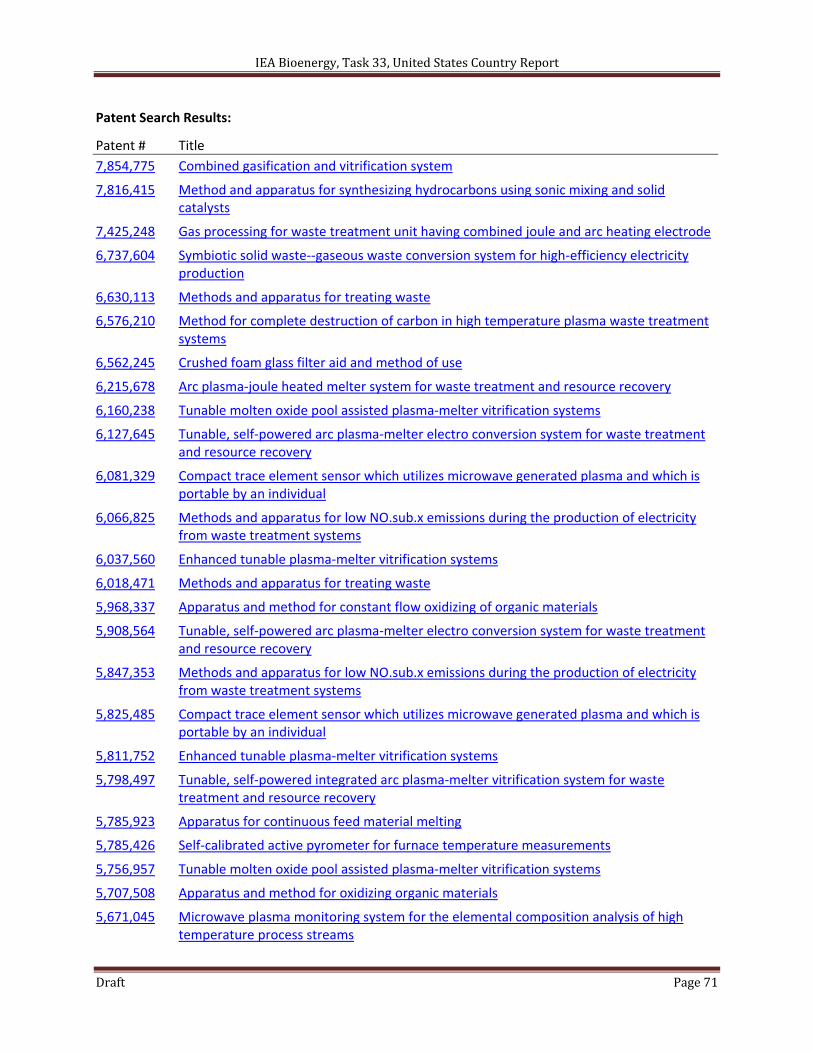
IEA Bioenergy, Task 33, United States Country Report
Draft Page 71
Patent Search Results:
Patent # Title
7,854,775 Combined gasification and vitrification system
7,816,415 Method and apparatus for synthesizing hydrocarbons using sonic mixing and solid catalysts
7,425,248 Gas processing for waste treatment unit having combined joule and arc heating electrode
6,737,604 Symbiotic solid waste‐‐gaseous waste conversion system for high‐efficiency electricity production
6,630,113 Methods and apparatus for treating waste
6,576,210 Method for complete destruction of carbon in high temperature plasma waste treatment systems
6,562,245 Crushed foam glass filter aid and method of use
6,215,678 Arc plasma‐joule heated melter system for waste treatment and resource recovery
6,160,238 Tunable molten oxide pool assisted plasma‐melter vitrification systems
6,127,645 Tunable, self‐powered arc plasma‐melter electro conversion system for waste treatment and resource recovery
6,081,329 Compact trace element sensor which utilizes microwave generated plasma and which is portable by an individual
6,066,825 Methods and apparatus for low NO.sub.x emissions during the production of electricity from waste treatment systems
6,037,560 Enhanced tunable plasma‐melter vitrification systems
6,018,471 Methods and apparatus for treating waste
5,968,337 Apparatus and method for constant flow oxidizing of organic materials
5,908,564 Tunable, self‐powered arc plasma‐melter electro conversion system for waste treatment and resource recovery
5,847,353 Methods and apparatus for low NO.sub.x emissions during the production of electricity from waste treatment systems
5,825,485 Compact trace element sensor which utilizes microwave generated plasma and which is portable by an individual
5,811,752 Enhanced tunable plasma‐melter vitrification systems
5,798,497 Tunable, self‐powered integrated arc plasma‐melter vitrification system for waste treatment and resource recovery
5,785,923 Apparatus for continuous feed material melting
5,785,426 Self‐calibrated active pyrometer for furnace temperature measurements
5,756,957 Tunable molten oxide pool assisted plasma‐melter vitrification systems
5,707,508 Apparatus and method for oxidizing organic materials
5,671,045 Microwave plasma monitoring system for the elemental composition analysis of high temperature process streams

IEA Bioenergy, Task 33, United States Country Report
Draft Page 72
5,666,891 ARC plasma‐melter electro conversion system for waste treatment and resource recovery
5,573,339 Active radiometer for self‐calibrated furnace temperature measurements
5,563,675 Special effects carrier
5,479,254 Continuous, real time microwave plasma element sensor
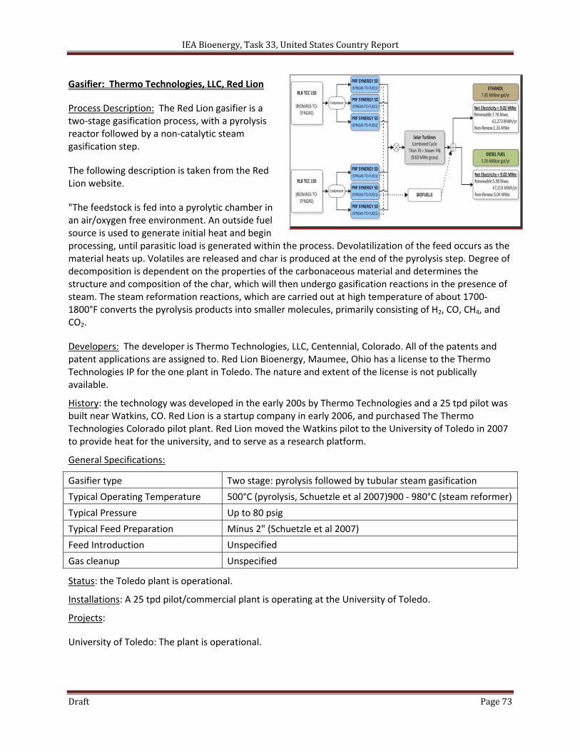
IEA Bioenergy, Task 33, United States Country Report
Draft Page 73
Gasifier: Thermo Technologies, LLC, Red Lion
Process Description: The Red Lion gasifier is a two‐stage gasification process, with a pyrolysis reactor followed by a non‐catalytic steam gasification step.
The following description is taken from the Red Lion website.
"The feedstock is fed into a pyrolytic chamber in an air/oxygen free environment. An outside fuel source is used to generate initial heat and begin processing, until parasitic load is generated within the process. Devolatilization of the feed occurs as the material heats up. Volatiles are released and char is produced at the end of the pyrolysis step. Degree of decomposition is dependent on the properties of the carbonaceous material and determines the structure and composition of the char, which will then undergo gasification reactions in the presence of steam. The steam reformation reactions, which are carried out at high temperature of about 1700‐1800°F converts the pyrolysis products into smaller molecules, primarily consisting of H2, CO, CH4, and CO2.
Developers: The developer is Thermo Technologies, LLC, Centennial, Colorado. All of the patents and patent applications are assigned to. Red Lion Bioenergy, Maumee, Ohio has a license to the Thermo Technologies IP for the one plant in Toledo. The nature and extent of the license is not publically available.
History: the technology was developed in the early 200s by Thermo Technologies and a 25 tpd pilot was built near Watkins, CO. Red Lion is a startup company in early 2006, and purchased The Thermo Technologies Colorado pilot plant. Red Lion moved the Watkins pilot to the University of Toledo in 2007 to provide heat for the university, and to serve as a research platform.
General Specifications:
Gasifier type Two stage: pyrolysis followed by tubular steam gasification
Typical Operating Temperature 500°C (pyrolysis, Schuetzle et al 2007)900 ‐ 980°C (steam reformer)
Typical Pressure Up to 80 psig
Typical Feed Preparation Minus 2" (Schuetzle et al 2007)
Feed Introduction Unspecified
Gas cleanup Unspecified
Status: the Toledo plant is operational.
Installations: A 25 tpd pilot/commercial plant is operating at the University of Toledo.
Projects:
University of Toledo: The plant is operational.
IEA Bioenergy, Task 33, United States Country Report
Draft Page 74
Renewable Energy Institute International, Gridley Project: the Red Lion Technology has been selected as the gasifier technology for a DOE Integrated Biorefinery project evaluating the production of Fischer‐Tropsch liquids at the 350 tpd scale. Pacific Renewable Fuels has been selected as the fuels synthesis technology.
Contacts:
Red Lion Bioenergy 387 West Dussel Drive Maumee, Ohio 45357 Ph: 419.897.6868 Fax: 419.897.6869
References:
Johnson, D., G. Abramov, R. Klienke, and M. Wiley (2009). "Method and apparatus for solid carbonaceous materials synthesis gas generation, United States Patent 7,638,070 B2, December 29.
Johnson, D., G. Abramov, R. Klienke, and M. Wiley (2009). "Methods and apparatus for solid carbonaceous materials synthesis gas generation," United States Patent Application 20090126276, May 21.
Johnson, D., G. Abramov, R. Klienke, and M. Wiley (2009). "Methods and apparatus for solid carbonaceous materials synthesis gas generation," United States Patent Application 20090270, May 21.
Johnson, D., G. Abramov, R. Klienke, and M. Wiley (2009). "Methods and apparatus for solid carbonaceous materials synthesis gas generation," United States Patent Application 20090119994, May 14.
Johnson, D., G. Abramov, R. Klienke, and M. Wiley (2009). "Methods and apparatus for solid carbonaceous materials synthesis gas generation," United States Patent Application 20090119992, May 14.
Johnson, D., G. Abramov, R. Klienke, and M. Wiley (2009). "Methods and apparatus for solid carbonaceous materials synthesis gas generation," United States Patent Application 20090119991, May 14.
Johnson, D., G. Abramov, R. Klienke, and M. Wiley (2009). "Methods and apparatus for solid carbonaceous materials synthesis gas generation," United States Patent Application 20090119990, May 14.
Johnson, D., G. Abramov, R. Klienke, and M. Wiley (2010). "Method and apparatus for solid carbonaceous materials synthesis gas generation, United States Patent 7,857,995, December 28.
Schuetzle, D., M. Caldwell, D. Granz, R. Hurley, G. Tamblyn, F. Tornatore, and A. Jackson (2007). "An assessment of biomass conversion technologies and recommendations in support of the deployment of a 450 ton/day integrated biofuels and energy production (IBEP) plant for the production of ethanol, electricity and heat from rice harvest waste and other agricultural biomass resources in Gridley, California," Phase I Interim Report, for the U.S. Department of Energy, DOE Contract DE‐FC36‐03GO13071, March.
Schuetzle, D. and G. Tamblyn (2010). "Demonstration of a pilot integrated biorefinery for the economical conversion of biomass to diesel fuel," Renewable Energy Institute International for2010 DOE IBR Platform Review, February 2.
Tamblyn, G. (2010). "Biomass Program – Gridley biofuels project," DOE IBR Fact Sheet, http://www1.eere.energy.gov/biomass/integrated_biorefineries.html, accessed June 1, 2011.
TSS Consultants (2005). "Gridley ethanol demonstration project utilizing biomass gasification technology: pilot plant gasifier and syngas conversion testing," for the National Renewable Energy Laboratory, Golden, CO, NREL/SR‐510‐37581, February.
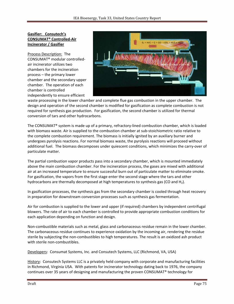
IEA Bioenergy, Task 33, United States Country Report
Draft Page 75
Gasifier: Consutech’s CONSUMAT® Controlled‐Air Incinerator / Gasifier
Process Description: The CONSUMAT® modular controlled‐air incinerator utilizes two chambers for the incineration process – the primary lower chamber and the secondary upper chamber. The operation of each chamber is controlled independently to ensure efficient waste processing in the lower chamber and complete flue gas combustion in the upper chamber. The design and operation of the second chamber is modified for gasification as complete combustion is not required for synthesis gas production. For gasification, the second chamber is utilized for thermal conversion of tars and other hydrocarbons.
The CONSUMAT® system is made up of a primary, refractory‐lined combustion chamber, which is loaded with biomass waste. Air is supplied to the combustion chamber at sub‐stoichiometric ratio relative to the complete combustion requirement. The biomass is initially ignited by an auxiliary burner and undergoes pyrolysis reactions. For normal biomass waste, the pyrolysis reactions will proceed without additional fuel. The biomass decomposes under quiescent conditions, which minimizes the carry‐over of particulate matter.
The partial combustion vapor products pass into a secondary chamber, which is mounted immediately above the main combustion chamber. For the incineration process, the gases are mixed with additional air at an increased temperature to ensure successful burn out of particulate matter to eliminate smoke. For gasification, the vapors from the first stage enter the second stage where the tars and other hydrocarbons are thermally decomposed at high temperatures to synthesis gas (CO and H2).
In gasification processes, the synthesis gas from the secondary chamber is cooled through heat recovery in preparation for downstream conversion processes such as synthesis gas fermentation.
Air for combustion is supplied to the lower and upper (if required) chambers by independent centrifugal blowers. The rate of air to each chamber is controlled to provide appropriate combustion conditions for each application depending on function and design.
Non‐combustible materials such as metal, glass and carbonaceous residue remain in the lower chamber. The carbonaceous residue continues to experience oxidation by the incoming air, rendering the residue sterile by subjecting the non‐combustibles to high temperatures. The result is an oxidized ash product with sterile non‐combustibles.
Developers: Consumat Systems, Inc. and Consutech Systems, LLC (Richmond, VA, USA)
History: Consutech Systems LLC is a privately held company with corporate and manufacturing facilities in Richmond, Virginia USA. With patents for incinerator technology dating back to 1976, the company continues over 35 years of designing and manufacturing the proven CONSUMAT® technology for

IEA Bioenergy, Task 33, United States Country Report
Draft Page 76
biomass waste combustion and air quality control equipment. Thousands of CONSUMAT® waste disposal systems have been installed throughout the world since 1965. In 2003, a Consutech gasifier design was incorporated into the BRI Energy process to generate synthesis gas from biomass waste for fuel‐grade ethanol production via synthesis gas fermentation pathway.
General Specifications:
Gasifier Type Direct air / oxygen blown partial oxidation with integrated thermal tar conversion step.
Typical Operating Temperature 1290 – 1370 °C (2350 – 2500 °F) for synthesis gas production
Typical Pressure 1 bar
Typical Feed Typical feed is trash, municipal and pathological wastes.
Gas Cleanup Tar conversion in secondary chamber. Two‐chamber design minimizes particulate carry‐over to downstream processes.
Status: CONSUMAT® Gasifier design incorporated into the Bioengineering Resources, Inc. (BRI) design for ethanol production from synthesis gas fermentation.
Installations: Consutech currently has the following project installed or in‐progress:
Model Capacity (LB/hour) Waste Type Location
C‐75PH‐1 200 Pathological USA
C‐32P 85 Pathological USA
C‐18P 75 Trash Soviet
C‐18P 75 Trash Soviet
C‐18P 75 Trash Soviet
C‐75PH 200 Pathological USA
C‐18P 75 Trash Soviet
C‐18P 75 Trash Iraq
C‐18P 75 Trash Iraq
C‐18P 75 Trash Iraq
C‐32P 130 Trash Soviet
C‐32P 130 Trash Soviet
C‐32P 130 Trash Soviet
C‐32P 130 Trash Soviet
Model Capacity (LB/hour) Waste Type Location
C‐32P 130 Trash Soviet
CS‐2700‐2 5333 Municipal Iraq
CS‐2700‐2 5333 Municipal Iraq
CS‐2700‐2 5333 Municipal Iraq
CS‐2700‐2 5333 Municipal Iraq
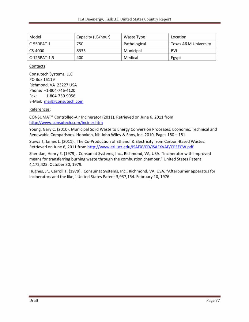
IEA Bioenergy, Task 33, United States Country Report
Draft Page 77
Model Capacity (LB/hour) Waste Type Location
C‐550PAT‐1 750 Pathological Texas A&M University
CS‐4000 8333 Municipal BVI
C‐125PAT‐1.5 400 Medical Egypt
Contacts:
Consutech Systems, LLC PO Box 15119 Richmond, VA 23227 USA Phone: +1‐804‐746‐4120 Fax: +1‐804‐730‐9056 E‐Mail: [email protected]
References:
CONSUMAT® Controlled‐Air Incinerator (2011). Retrieved on June 6, 2011 from http://www.consutech.com/inciner.htm
Young, Gary C. (2010). Municipal Solid Waste to Energy Conversion Processes: Economic, Technical and Renewable Comparisons. Hoboken, NJ: John Wiley & Sons, Inc. 2010. Pages 180 – 181.
Stewart, James L. (2011). The Co‐Production of Ethanol & Electricity from Carbon‐Based Wastes. Retrieved on June 6, 2011 from http://www.eri.ucr.edu/ISAFXVCD/ISAFXVAF/CPEECW.pdf
Sheridan, Henry E. (1979). Consumat Systems, Inc., Richmond, VA, USA. “Incinerator with improved means for transferring burning waste through the combustion chamber,” United States Patent 4,172,425. October 30, 1979.
Hughes, Jr., Carroll T. (1979). Consumat Systems, Inc., Richmond, VA, USA. “Afterburner apparatus for incinerators and the like,” United States Patent 3,937,154. February 10, 1976.
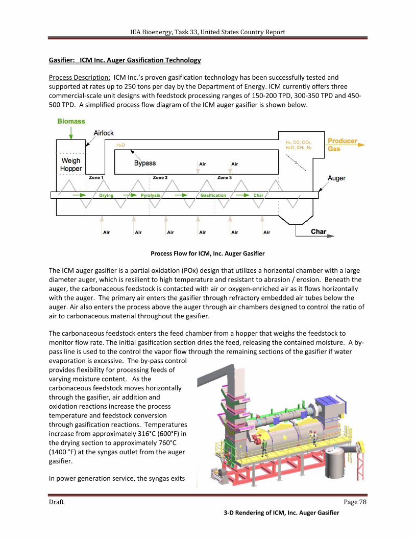
IEA Bioenergy, Task 33, United States Country Report
Draft Page 78
Gasifier: ICM Inc. Auger Gasification Technology
Process Description: ICM Inc.’s proven gasification technology has been successfully tested and supported at rates up to 250 tons per day by the Department of Energy. ICM currently offers three commercial‐scale unit designs with feedstock processing ranges of 150‐200 TPD, 300‐350 TPD and 450‐500 TPD. A simplified process flow diagram of the ICM auger gasifier is shown below.
Process Flow for ICM, Inc. Auger Gasifier
The ICM auger gasifier is a partial oxidation (POx) design that utilizes a horizontal chamber with a large diameter auger, which is resilient to high temperature and resistant to abrasion / erosion. Beneath the auger, the carbonaceous feedstock is contacted with air or oxygen‐enriched air as it flows horizontally with the auger. The primary air enters the gasifier through refractory embedded air tubes below the auger. Air also enters the process above the auger through air chambers designed to control the ratio of air to carbonaceous material throughout the gasifier.
The carbonaceous feedstock enters the feed chamber from a hopper that weighs the feedstock to monitor flow rate. The initial gasification section dries the feed, releasing the contained moisture. A by‐pass line is used to the control the vapor flow through the remaining sections of the gasifier if water evaporation is excessive. The by‐pass control provides flexibility for processing feeds of varying moisture content. As the carbonaceous feedstock moves horizontally through the gasifier, air addition and oxidation reactions increase the process temperature and feedstock conversion through gasification reactions. Temperatures increase from approximately 316°C (600°F) in the drying section to approximately 760°C (1400 °F) at the syngas outlet from the auger gasifier.
In power generation service, the syngas exits
3‐D Rendering of ICM, Inc. Auger Gasifier
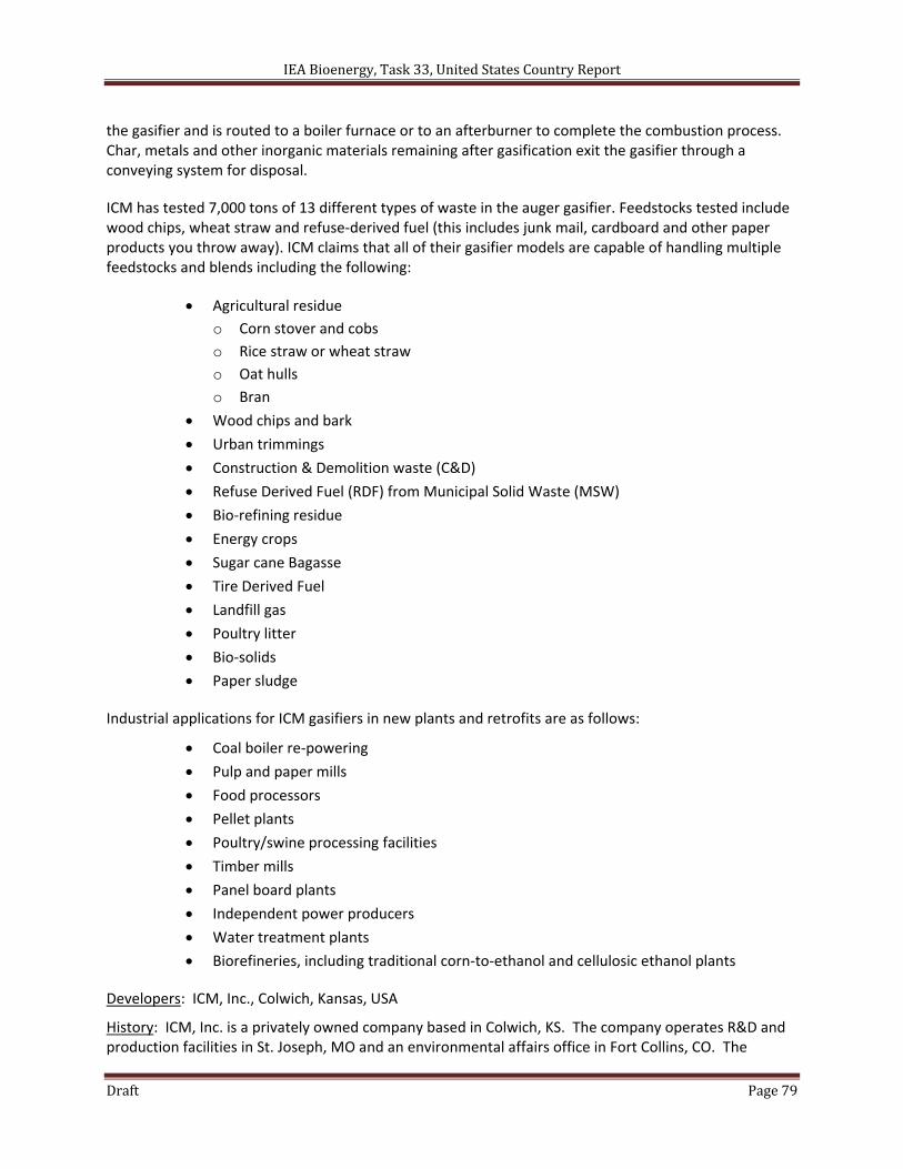
IEA Bioenergy, Task 33, United States Country Report
Draft Page 79
the gasifier and is routed to a boiler furnace or to an afterburner to complete the combustion process. Char, metals and other inorganic materials remaining after gasification exit the gasifier through a conveying system for disposal.
ICM has tested 7,000 tons of 13 different types of waste in the auger gasifier. Feedstocks tested include wood chips, wheat straw and refuse‐derived fuel (this includes junk mail, cardboard and other paper products you throw away). ICM claims that all of their gasifier models are capable of handling multiple feedstocks and blends including the following:
Agricultural residue
o Corn stover and cobs
o Rice straw or wheat straw
o Oat hulls
o Bran
Wood chips and bark
Urban trimmings
Construction & Demolition waste (C&D)
Refuse Derived Fuel (RDF) from Municipal Solid Waste (MSW)
Bio‐refining residue
Energy crops
Sugar cane Bagasse
Tire Derived Fuel
Landfill gas
Poultry litter
Bio‐solids
Paper sludge
Industrial applications for ICM gasifiers in new plants and retrofits are as follows:
Coal boiler re‐powering
Pulp and paper mills
Food processors
Pellet plants
Poultry/swine processing facilities
Timber mills
Panel board plants
Independent power producers
Water treatment plants
Biorefineries, including traditional corn‐to‐ethanol and cellulosic ethanol plants
Developers: ICM, Inc., Colwich, Kansas, USA
History: ICM, Inc. is a privately owned company based in Colwich, KS. The company operates R&D and production facilities in St. Joseph, MO and an environmental affairs office in Fort Collins, CO. The
IEA Bioenergy, Task 33, United States Country Report
Draft Page 80
company’s mission is to provide innovative technologies, solutions, and services to sustain agriculture and advance renewable energy, including food and feed technologies that will increase the supply of world protein.
The company was founded in 1995 by Dave Vander Griend, who remains president and CEO today. The company’s original goal was to engineer and build the industry’s safest and most efficient distiller grain dryers. ICM also offered commodity marketing services dealing in ethanol and distillers grains.
ICM currently offers the following products and services to the U.S. and Canadian ethanol industries:
Process engineering, project management, training, and start‐up services for 102 plants
General contracting and process equipment maintenance services for 27 plants
Retrofits, operations and engineering assistance to other fuel ethanol technologies
ICM manufactures, maintains and supports the following types of process equipment for the ethanol and carbonaceous materials recycle industries.
DDG Dryers
Thermal Oxidizers
Small Tanks & Equipment
Methanators
Gasifiers
General Specifications:
Gasifier Type Auger (screw conveyer) gasifier
Typical Operating Temperature Feed drying at approximately 316°C (600°F) to syngas outlet temperature of approximately 760°C (1400°F)
Typical Pressure Vacuum to atmospheric
Feed Preparation and Introduction
Front‐end loaders, feed conveyor, metering hopper. Feedstock particle size not identified in research.
Gas Cleanup
(refer to image below)
Particulate removal
Staged injection of air & flue gas recycle
NOx control – selective non‐catalytic reduction
Dry sorbent injection
Dual‐field wet ESP – strategic alliance with Eisenmann Corp.
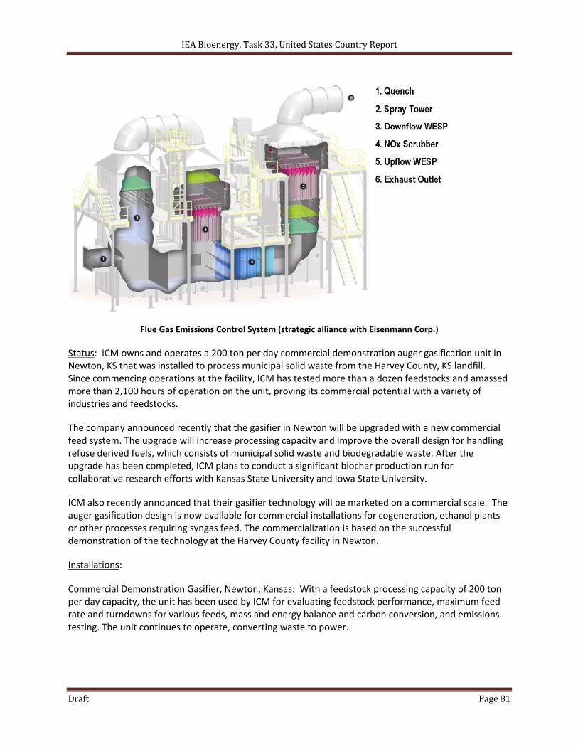
IEA Bioenergy, Task 33, United States Country Report
Draft Page 81
Flue Gas Emissions Control System (strategic alliance with Eisenmann Corp.)
Status: ICM owns and operates a 200 ton per day commercial demonstration auger gasification unit in Newton, KS that was installed to process municipal solid waste from the Harvey County, KS landfill. Since commencing operations at the facility, ICM has tested more than a dozen feedstocks and amassed more than 2,100 hours of operation on the unit, proving its commercial potential with a variety of industries and feedstocks.
The company announced recently that the gasifier in Newton will be upgraded with a new commercial feed system. The upgrade will increase processing capacity and improve the overall design for handling refuse derived fuels, which consists of municipal solid waste and biodegradable waste. After the upgrade has been completed, ICM plans to conduct a significant biochar production run for collaborative research efforts with Kansas State University and Iowa State University.
ICM also recently announced that their gasifier technology will be marketed on a commercial scale. The auger gasification design is now available for commercial installations for cogeneration, ethanol plants or other processes requiring syngas feed. The commercialization is based on the successful demonstration of the technology at the Harvey County facility in Newton.
Installations:
Commercial Demonstration Gasifier, Newton, Kansas: With a feedstock processing capacity of 200 ton per day capacity, the unit has been used by ICM for evaluating feedstock performance, maximum feed rate and turndowns for various feeds, mass and energy balance and carbon conversion, and emissions testing. The unit continues to operate, converting waste to power.
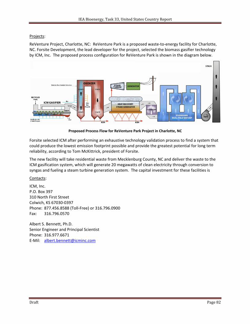
IEA Bioenergy, Task 33, United States Country Report
Draft Page 82
Projects:
ReVenture Project, Charlotte, NC: ReVenture Park is a proposed waste‐to‐energy facility for Charlotte, NC. Forsite Development, the lead developer for the project, selected the biomass gasifier technology by ICM, Inc. The proposed process configuration for ReVenture Park is shown in the diagram below.
Proposed Process Flow for ReVenture Park Project in Charlotte, NC
Forsite selected ICM after performing an exhaustive technology validation process to find a system that could produce the lowest emission footprint possible and provide the greatest potential for long term reliability, according to Tom McKittrick, president of Forsite.
The new facility will take residential waste from Mecklenburg County, NC and deliver the waste to the ICM gasification system, which will generate 20 megawatts of clean electricity through conversion to syngas and fueling a steam turbine generation system. The capital investment for these facilities is
Contacts:
ICM, Inc. P.O. Box 397 310 North First Street Colwich, KS 67030‐0397 Phone: 877.456.8588 (Toll‐Free) or 316.796.0900 Fax: 316.796.0570
Albert S. Bennett, Ph.D. Senior Engineer and Principal Scientist Phone: 316.977.6671 E‐Mil: [email protected]
IEA Bioenergy, Task 33, United States Country Report
Draft Page 83
References:
ICM, Inc. Gasifier: Proven technology to process multiple feedstocks (2011). Retrieved on June 10, 2011 from http://www.icminc.com/pdf/ProductLines/Gasifier.pdf
ICM, Inc. (2011). “ICM Gasification Technology,” Presented to the United State Department of Agriculture – Agricultural Research Service via teleseminar. February 8, 2011. http://www.ars.usda.gov/SP2UserFiles/Program/213/Teleseminars/ICM%20teleseminar%20(02‐08‐11).pdf
ICM, Inc. (2009). “Product Overview: Gasification,” March 2009. http://www.kdheks.gov/waste/workshops/works09/presentations/heuer‐gasification.pdf
McCoy, Daniel (2009). "ICM gasifier plant at Harvey County landfill working to turn trash to energy". Wichita Business Journal. April 26, 2009. Retrieved on June 10, 2011 from http://www.bizjournals.com/wichita/stories/2009/04/27/story6.html
Charlotte, NC Chamber of Economic Development (2010). " Forsite Development Chooses ICM, Inc. to Provide Gasifier Technology for ReVenture Park – 145 new jobs to be created". Press release from December 2, 2010. Retrieved on June 10, 2011 from http://www.reventurepark.com/uploads/Forsite12‐2‐10_Chamber_Announcement_Forsite_ICM.pdf
Bergner, Ashley (2011). "ICM develops new renewable source of energy from waste". The Newton Kansan. March 7, 2011. Retrieved on June 10, 2011 from http://icminc.com/pdf/headlines/March_5_2011_Newton_Kansan_article_on_gasifier.pdf
Garcia, Monique (2011). "ICM, Inc. Adds New Commercial Feed System to Its Biomass Gasifier System in Harvey County ". The Newton Kansan. April 4, 2011. Retrieved on June 10, 2011 from http://www.thekansan.com/business/x1700896304/ICM‐adds‐new‐commercial‐feed‐system‐to‐its‐gasifier‐System‐in‐Harvey‐County
Bevill, Kris (2011). "ICM debuts commercial‐scale biomass gasifier". Ethanol Producer Magazine. May 10, 2011. Retrieved on June 10, 2011 from http://www.ethanolproducer.com/articles/7747/icm‐debuts‐commercial‐scale‐biomass‐gasifier
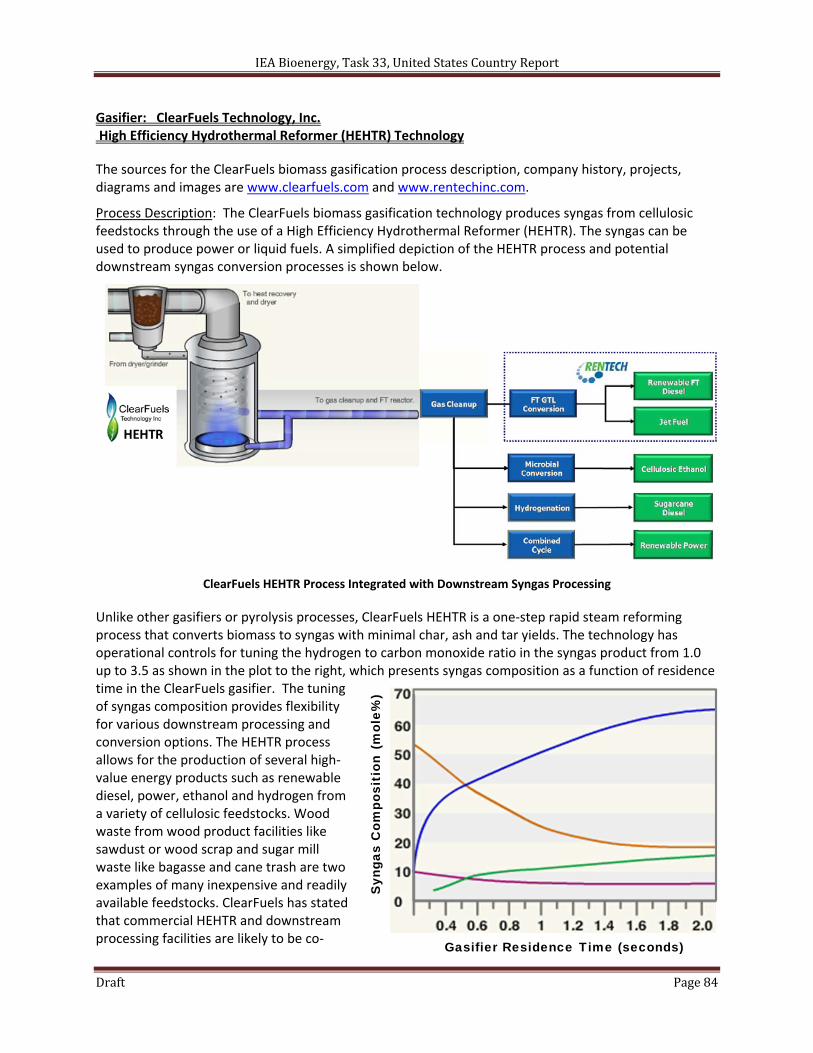
IEA Bioenergy, Task 33, United States Country Report
Draft Page 84
Gasifier: ClearFuels Technology, Inc. High Efficiency Hydrothermal Reformer (HEHTR) Technology
The sources for the ClearFuels biomass gasification process description, company history, projects, diagrams and images are www.clearfuels.com and www.rentechinc.com.
Process Description: The ClearFuels biomass gasification technology produces syngas from cellulosic feedstocks through the use of a High Efficiency Hydrothermal Reformer (HEHTR). The syngas can be used to produce power or liquid fuels. A simplified depiction of the HEHTR process and potential downstream syngas conversion processes is shown below.
ClearFuels HEHTR Process Integrated with Downstream Syngas Processing
Unlike other gasifiers or pyrolysis processes, ClearFuels HEHTR is a one‐step rapid steam reforming process that converts biomass to syngas with minimal char, ash and tar yields. The technology has operational controls for tuning the hydrogen to carbon monoxide ratio in the syngas product from 1.0 up to 3.5 as shown in the plot to the right, which presents syngas composition as a function of residence time in the ClearFuels gasifier. The tuning of syngas composition provides flexibility for various downstream processing and conversion options. The HEHTR process allows for the production of several high‐value energy products such as renewable diesel, power, ethanol and hydrogen from a variety of cellulosic feedstocks. Wood waste from wood product facilities like sawdust or wood scrap and sugar mill waste like bagasse and cane trash are two examples of many inexpensive and readily available feedstocks. ClearFuels has stated that commercial HEHTR and downstream processing facilities are likely to be co‐
HEHTR
Gasifier Residence Time (seconds)
Syn
gas
Com
posi
tion
(m
ole%
)
IEA Bioenergy, Task 33, United States Country Report
Draft Page 85
located with existing sugar mills and wood product facilities, which will reduce operating costs and increase operating efficiencies.
A summary of the ClearFuels HEHTR process design features and anticipated benefits are summarized in the table below.
Design Feature Result Benefit
Indirect firing Combustion separate from gasification and gasified products
Cleaner syngas with low tar content
Steam reforming No air separation unit or nitrogen dilution required for the process
Lower capital and operating costs
Entrained flow Biomass and steam are premixed Consistent syngas characteristics with multiple feedstock's
Variable controls Independent control of steam, biomass and gasifier residence time
Ability to control H2 to CO ratio to desired through process control
Flexible fuel Process can use syngas, natural gas, Biogas or tailgas
Higher yields when integrated with other advance biofuels processes
Developers: Dow‐Destia, Pearson Technology Inc, ClearFuels Technology, Inc., Rentech, Inc.
History: Since the mid‐1990’s, ClearFuels founders were evaluating viable cellulosic ethanol conversion technologies to support a competitive business model that would deliver commercial‐scale production of cellulosic biofuels with minimal commodity risk and an efficient modular facility design. The basis for the ClearFuels technology was developed by Pearson Technology Inc. (PTI). The PTI technology was tested and validated at PTI’s pilot scale facility in Mississippi between 1987 and 2002.
The performance of the PTI technology was further corroborated using bagasse as a feedstock during extensive testing funded by ClearFuels at the PTI facility between 2004 and 2007. The success at the pilot plant have been independently validated by multiple third parties, minimizing the uncertainty and technology risk associated with scale up from the PTI pilot scale to the ClearFuels demonstration facilities and, ultimately, to full scale commercial production.
The extensive testing of the technology at pilot‐scale yielded a solid understanding of the biomass‐to‐syngas conversion process. ClearFuels, along with fabrication partners, has further developed and modified the basic technology for commercial application to meet the performance requirements for ClearFuels’ projected commercial biorefineries. The process and key components of the ClearFuels’ system have been optimized to reduce capital and operating costs while maximizing product yields.
In April 2011, Rentech, Inc. completed the acquisition of a substantial majority of the equity ownership of ClearFuels Technology Inc. with ClearFuels continuing as a Hawaiian company, and existing ClearFuels investors retaining a minority interest. The acquisition enables Rentech to add the ClearFuels biomass gasifier to the Company's suite of energy conversion technologies, which allows Rentech to offer multiple integrated systems to convert a wide variety of cellulosic materials into renewable fuels.
General Specifications:
Gasifier Type Indirect steam, entrained flow
Typical Operating Temperature Not identified in research
Typical Pressure Not identified in research
Feed Preparation and Introduction Not identified in research
Gas Cleanup Not identified in research
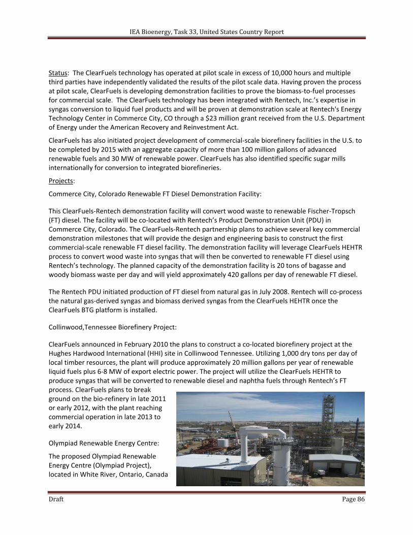
IEA Bioenergy, Task 33, United States Country Report
Draft Page 86
Status: The ClearFuels technology has operated at pilot scale in excess of 10,000 hours and multiple third parties have independently validated the results of the pilot scale data. Having proven the process at pilot scale, ClearFuels is developing demonstration facilities to prove the biomass‐to‐fuel processes for commercial scale. The ClearFuels technology has been integrated with Rentech, Inc.’s expertise in syngas conversion to liquid fuel products and will be proven at demonstration scale at Rentech's Energy Technology Center in Commerce City, CO through a $23 million grant received from the U.S. Department of Energy under the American Recovery and Reinvestment Act.
ClearFuels has also initiated project development of commercial‐scale biorefinery facilities in the U.S. to be completed by 2015 with an aggregate capacity of more than 100 million gallons of advanced renewable fuels and 30 MW of renewable power. ClearFuels has also identified specific sugar mills internationally for conversion to integrated biorefineries.
Projects:
Commerce City, Colorado Renewable FT Diesel Demonstration Facility:
This ClearFuels‐Rentech demonstration facility will convert wood waste to renewable Fischer‐Tropsch (FT) diesel. The facility will be co‐located with Rentech’s Product Demonstration Unit (PDU) in Commerce City, Colorado. The ClearFuels‐Rentech partnership plans to achieve several key commercial demonstration milestones that will provide the design and engineering basis to construct the first commercial‐scale renewable FT diesel facility. The demonstration facility will leverage ClearFuels HEHTR process to convert wood waste into syngas that will then be converted to renewable FT diesel using Rentech’s technology. The planned capacity of the demonstration facility is 20 tons of bagasse and woody biomass waste per day and will yield approximately 420 gallons per day of renewable FT diesel.
The Rentech PDU initiated production of FT diesel from natural gas in July 2008. Rentech will co‐process the natural gas‐derived syngas and biomass derived syngas from the ClearFuels HEHTR once the ClearFuels BTG platform is installed.
Collinwood,Tennessee Biorefinery Project:
ClearFuels announced in February 2010 the plans to construct a co‐located biorefinery project at the Hughes Hardwood International (HHI) site in Collinwood Tennessee. Utilizing 1,000 dry tons per day of local timber resources, the plant will produce approximately 20 million gallons per year of renewable liquid fuels plus 6‐8 MW of export electric power. The project will utilize the ClearFuels HEHTR to produce syngas that will be converted to renewable diesel and naphtha fuels through Rentech’s FT process. ClearFuels plans to break ground on the bio‐refinery in late 2011 or early 2012, with the plant reaching commercial operation in late 2013 to early 2014.
Olympiad Renewable Energy Centre:
The proposed Olympiad Renewable Energy Centre (Olympiad Project), located in White River, Ontario, Canada
IEA Bioenergy, Task 33, United States Country Report
Draft Page 87
will be designed as a state‐of‐the‐art energy facility that would employ the ClearFuels biomass gasification system and the Rentech FT process. The project would produce 23 million gallons of renewable jet fuel and 13 million gallons of renewable naphtha per year. The fuel and naphtha will be produced from 1.3 million tons per year of Crown timber allotted to Rentech by the Province of Ontario. Based on the recent publicly announced project schedule, the project is expected to be on‐line in 2015.
Contacts:
ClearFuels Technology, Inc. Hawaii Agriculture Research Center 99‐193 Aiea Heights Drive, Suite 308 Aiea, HI, 96701 Partnership opportunities with ClearFuels: [email protected] Investment opportunities within ClearFuels: [email protected] Contact Sandy Shiraki for other inquiries: [email protected]
References:
ClearFuels Technology, Inc. Gasification Technology (2011). Retrieved on June 10, 2011 from http://www.clearfuels.com/technology.php
Rentech‐ClearFuels Biomass Gasification Process (2011). Retrieved on June 10, 2011 from http://www.rentechinc.com/gasifier.php
Rentech, Inc. (2011). "Rentech Completes Acquisition of Majority of ClearFuels Technology Inc.". Press release from May 17, 2011. Retrieved on June 10, 2011 from http://phx.corporate‐ir.net/phoenix.zhtml?c=66629&p=irol‐newsArticle&ID=1564716&highlight
Lane, Jim (2011). "The New Economics of Next‐Gen Gasification: ClearFuels Technology". Biofuels Digest. January 10, 2011. Retrieved on June 10, 2011 from http://biofuelsdigest.com/bdigest/2011/01/10/the‐new‐economics‐of‐next‐gen‐gasification‐clearfuels‐technology/
ClearFuels Technology, Inc. (2010). "ClearFuels and Rentech Selected by U.S. Department of Energy for Integrated Bio‐Refinery Grant". Press release from December 7, 2010. Retrieved on June 10, 2011 from http://www.clearfuels.com/pdf/CF‐RTK_DOE_Grant_Award_FINAL.pdf
ClearFuels Technology, Inc. and Rentech, Inc. (2010). “Advanced Thermochemical Production of Drop in Biofuels,” Presented to the Biomass Research and Development Technical Advisory Committee. September 29, 2010. http://www.usbiomassboard.gov/pdfs/clearfuels_presentation_doe_panel_9_29_10_jbp2‐wkd2.pdf
U.S. Department of Energy, Energy Efficiency & Renewable Power, Biomass Program (2010). "The Integrated Pilot Project for Fuel Production by Thermochemical Conversion of Woodwaste". Integrated Biorefinery Factsheet. March 2, 2010. Retrieved on June 10, 2011 from http://www1.eere.energy.gov/biomass/pdfs/ibr_arra_clearfuelstechnology.pdf
Vantine, Bruce (2004). “Pearson Technologies, Inc,” Presented at the Southern Alliance for the Utilization of Biomass Resources Conference, University of Alabama. October 25 – 26, 2004. http://saubr.ua.edu/saubrpresentations/Bruce%20Vantine.pdf
Pearson, Stanley R. (2008). Pearson Technologies, Inc., Aberdeen, Mississippi, USA. “Process and apparatus for the production of useful products from carbonaceous feedstock,” United States Patent 7,375,142. May 20, 2008.
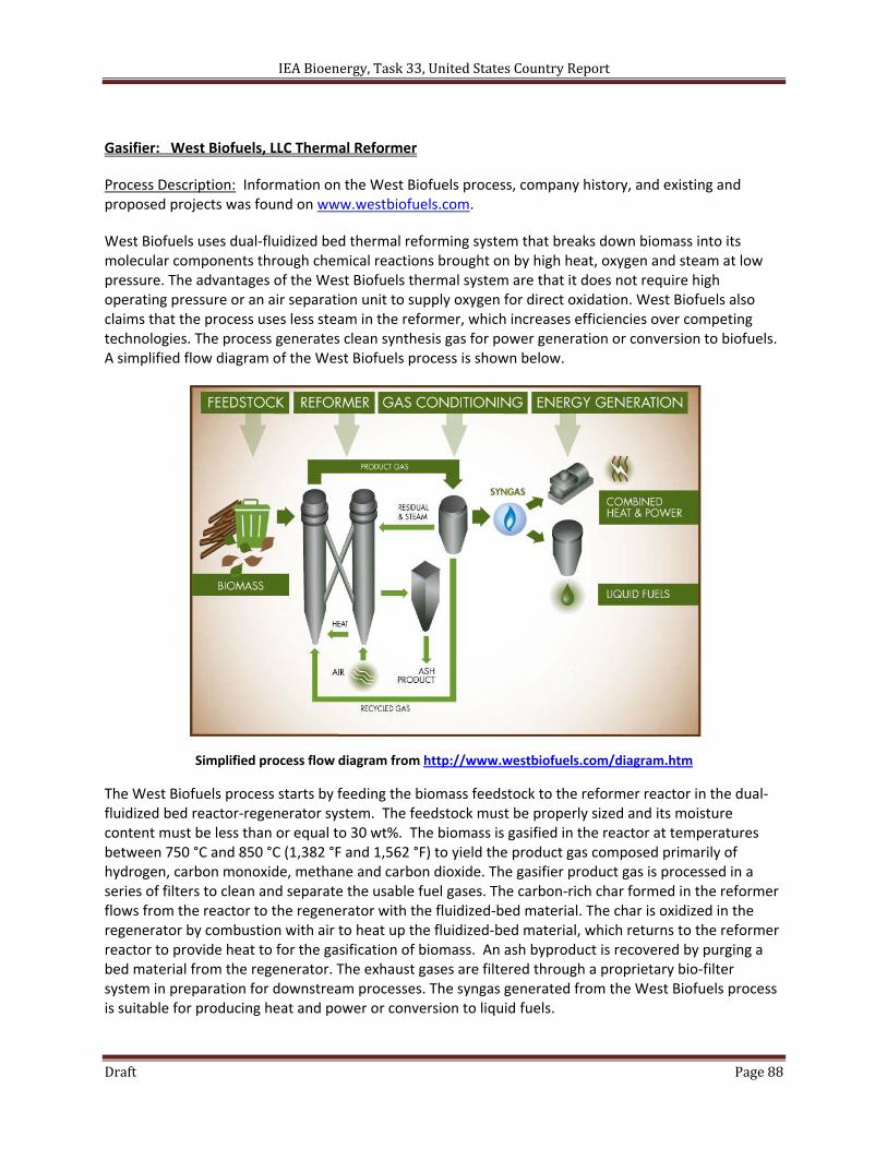
IEA Bioenergy, Task 33, United States Country Report
Draft Page 88
Gasifier: West Biofuels, LLC Thermal Reformer
Process Description: Information on the West Biofuels process, company history, and existing and proposed projects was found on www.westbiofuels.com.
West Biofuels uses dual‐fluidized bed thermal reforming system that breaks down biomass into its molecular components through chemical reactions brought on by high heat, oxygen and steam at low pressure. The advantages of the West Biofuels thermal system are that it does not require high operating pressure or an air separation unit to supply oxygen for direct oxidation. West Biofuels also claims that the process uses less steam in the reformer, which increases efficiencies over competing technologies. The process generates clean synthesis gas for power generation or conversion to biofuels. A simplified flow diagram of the West Biofuels process is shown below.
Simplified process flow diagram from http://www.westbiofuels.com/diagram.htm
The West Biofuels process starts by feeding the biomass feedstock to the reformer reactor in the dual‐fluidized bed reactor‐regenerator system. The feedstock must be properly sized and its moisture content must be less than or equal to 30 wt%. The biomass is gasified in the reactor at temperatures between 750 °C and 850 °C (1,382 °F and 1,562 °F) to yield the product gas composed primarily of hydrogen, carbon monoxide, methane and carbon dioxide. The gasifier product gas is processed in a series of filters to clean and separate the usable fuel gases. The carbon‐rich char formed in the reformer flows from the reactor to the regenerator with the fluidized‐bed material. The char is oxidized in the regenerator by combustion with air to heat up the fluidized‐bed material, which returns to the reformer reactor to provide heat to for the gasification of biomass. An ash byproduct is recovered by purging a bed material from the regenerator. The exhaust gases are filtered through a proprietary bio‐filter system in preparation for downstream processes. The syngas generated from the West Biofuels process is suitable for producing heat and power or conversion to liquid fuels.
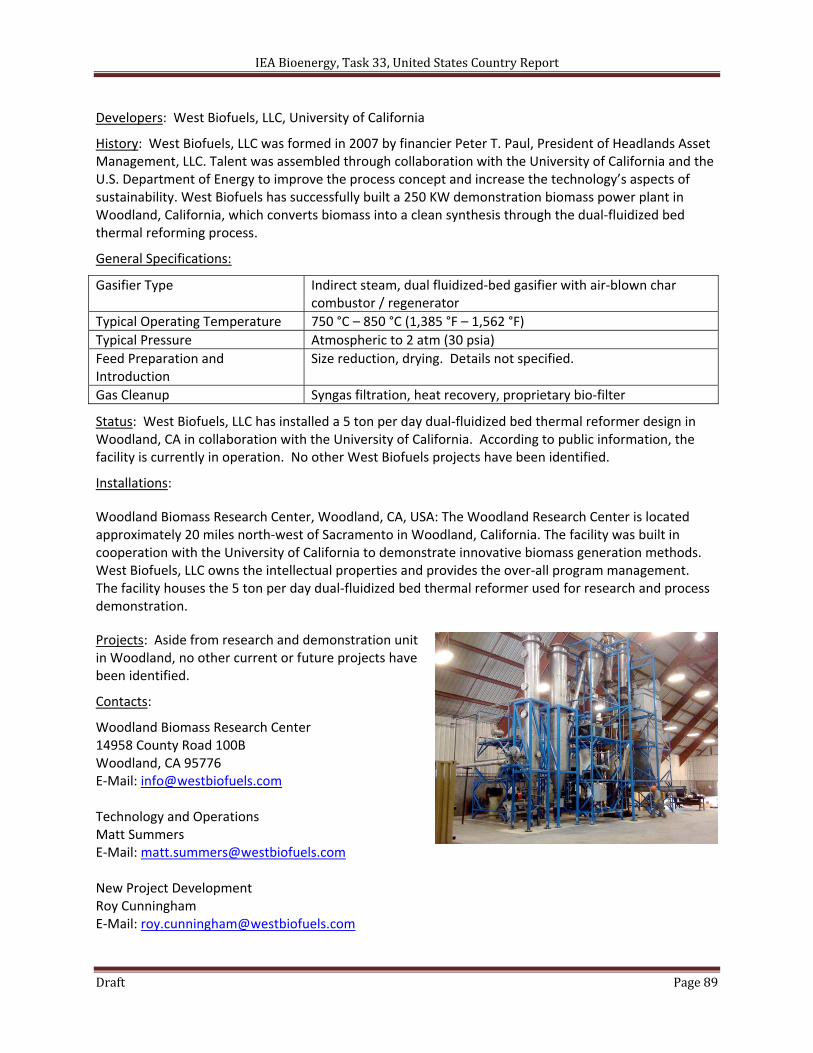
IEA Bioenergy, Task 33, United States Country Report
Draft Page 89
Developers: West Biofuels, LLC, University of California
History: West Biofuels, LLC was formed in 2007 by financier Peter T. Paul, President of Headlands Asset Management, LLC. Talent was assembled through collaboration with the University of California and the U.S. Department of Energy to improve the process concept and increase the technology’s aspects of sustainability. West Biofuels has successfully built a 250 KW demonstration biomass power plant in Woodland, California, which converts biomass into a clean synthesis through the dual‐fluidized bed thermal reforming process.
General Specifications:
Gasifier Type Indirect steam, dual fluidized‐bed gasifier with air‐blown char combustor / regenerator
Typical Operating Temperature 750 °C – 850 °C (1,385 °F – 1,562 °F)
Typical Pressure Atmospheric to 2 atm (30 psia)
Feed Preparation and Introduction
Size reduction, drying. Details not specified.
Gas Cleanup Syngas filtration, heat recovery, proprietary bio‐filter
Status: West Biofuels, LLC has installed a 5 ton per day dual‐fluidized bed thermal reformer design in Woodland, CA in collaboration with the University of California. According to public information, the facility is currently in operation. No other West Biofuels projects have been identified.
Installations:
Woodland Biomass Research Center, Woodland, CA, USA: The Woodland Research Center is located approximately 20 miles north‐west of Sacramento in Woodland, California. The facility was built in cooperation with the University of California to demonstrate innovative biomass generation methods. West Biofuels, LLC owns the intellectual properties and provides the over‐all program management. The facility houses the 5 ton per day dual‐fluidized bed thermal reformer used for research and process demonstration.
Projects: Aside from research and demonstration unit in Woodland, no other current or future projects have been identified.
Contacts:
Woodland Biomass Research Center 14958 County Road 100B Woodland, CA 95776 E‐Mail: [email protected] Technology and Operations Matt Summers E‐Mail: [email protected] New Project Development Roy Cunningham E‐Mail: [email protected]

IEA Bioenergy, Task 33, United States Country Report
Draft Page 90
References:
West Biofuels, LLC Technology (2011). Retrieved on June 15, 2011 from http://www.westbiofuels.com Bain, Richard L. (2009). “Status of U.S. Biomass Gasification,” Presented at Task Meeting, IEA Bioenergy, Task 33. May 14, 2009. http://media.godashboard.com/gti/IEA_Task33_USA_May2009.pdf
Evangelista, Andy (2010). “Research grants reap products and partnerships,” UC Office of the President Strategic Communications Department. Press release from July 19, 2010. Retrieved on June 15, 2011 from http://www.californiawheat.org/news/detail.asp?newsID=65&printable=1