Embed Size (px)
Citation preview
UNIVERSITI TEKNIKAL MALAYSIA MELAKA
DEVELOPMENT OF KNEE BRACES FOR OSTEOARTHRITIS
PATIENT
This report submitted in accordance with requirement of the Universiti Teknikal
Malaysia Melaka (UTeM) for the Bachelor Degree of Manufacturing Engineering
Technology
(Product Design) with Honours.
by
MUHAMAD HUSNI BIN HUSSEIN
B071110369
890131-01-5577
FACULTY OF ENGINEERING TECHNOLOGY
2015
DECLARATION
I hereby, declared this report entitled “DEVELOPMENT OF KNEE BRACES FOR
OSTEOARTHRITIS PATIENT” is the results of my own research except as cited in
the references.
Signature :
Author’s Name : MUHAMAD HUSNI BIN HUSSEIN
Date :
APPROVAL
This report is submitted to the Faculty of Engineering Technology of UTeM as a
partial fulfillment of the requirements for the degree of Bachelor of Manufacturing
Engineering Technology (Product Design) with Honours. The member of the
supervisory committee is as follows:
(Signature of Supervisor)
………………………………
APPROVAL
This report is submitted to the Faculty of Engineering Technology of UTeM as a
partial fulfillment of the requirements for the degree of Bachelor of Manufacturing
Engineering Technology (Product Design) with Honours. The members of the
supervisory committee are as follows:
(Signature of Principal Supervisor)
………………………………
i
ABSTRAK
Dalam tesis ini, untuk mereka bentuk semula mekanisme dan membuat penambahbaik
peranti pemulihan bagi kelemahan lutut berfungsi dibentangkan. Tujuan mereka bentuk
semula ini adalah untuk membantu lutut pesakit lemah berfungsi dalam proses
pemulihan. Kajian literatur digunakan untuk mengenal pasti dan penyelesaian masalah
pada reka bentuk yang sedia ada dan untuk mengumpul data spesifikasi peranti
pemulihan yang sedia ada sebelum process pembangunan konsep reka bentuk
dilaksanakan. Konsep mereka bentuk peranti pemulihan yang telah dibangunkan
berdasarkan criteria reka bentuk produk. Reka bentuk akhir akan dipilih dengan
menggunakan kaedah yang sesuai iaitu kaedah saringan dan pemarkahan. Dengan
menggunakan perisian Solidwork, model reka bentuk akhir telah berjaya dibangunkan
dan digunakan untuk menganalisis komponen kritikal pada peranti. Keputusan daripada
analisis bahagian kritikal menunjukkan bahawa reka bentuk yang dicadangkan boleh
digunakan dengan selamat.
ii
ABSTRACT
There is a need, to redesign and improve the mechanism and functional of rehabilitation
device for knee functional weakness. The purpose is to help the knee functional
weakness, patient in the process of rehabilitation. Literature study used to identify the
problems and solutions of the existing design and to collect specification data and patent
of an existing device before the development process of conceptual design is
implemented. The conceptual designs have been developed based on product design
criteria. The final design has been selected by using suitable methods which are
screening and scoring methods. By using software Solidwork, the model of the final
design has been successfully developed and used to analyze the critical component of
the device. Result from the analysis of critical part indicates that the proposed design is
possible to use safely.
iii
DEDICATION
I would first like to express heartfelt thanks for the warmth of love to my adored
Parents:
Mr. Hussein Bin Daing Diduk
Mrs. Siti Asnah Binti Hj Daeng Matata
And for my respected Brother and Sister:
Siti Norhidayah Binti Hussein
Mohd Taufiq Bin Hussein
Muhammad Hanif Bin Hussein
Haziq Aiman Bin Hussein
Thanks you for the endless support and loves to me..
May God bless those who have been giving me their support to excellence further
in my future undertakings.
iv
ACKNOWLEDGEMENT
First of all, I would like to thank to my supervisor, Engr Hassan Bin Attan for giving me
a lot of knowledge and a lot of information during this final year project period. Without
his support and encouragement I can’t afford to complete this final year project
I also would like to thank all of my lecturers in Universiti Teknikal Malaysia Melaka
(UTeM) who have helped me from the beginning until the end of this final year project
period. Without their support and advice I can never complete this technical report with
success.
Special thanks to my fellow friend, for helping me most in getting the information and
detail about everything that related to this final project. They give full commitment in
helping me finding the solution to my problem and solve it together. Not to be forget to
all my family members because they had given a lot of support and attention to me in
doing and finishing with success on this final year project. I really appreciated for what
you guys have done for me.
Not to be forget to all my family members because they had given a lot of support and
attention for me to finish with success on this final year project. I really appreciated for
what you guys have done for me.
THANK YOU SO MUCH
v
TABLE OF CONTENTS
Abstrak i
Abstract ii
Dedication iii
Acknowledgement iv
Table of Content v
List of Table vi
List of Figure vii
1. INTRODUCTION 1
1.1 Background of Study 1
1.2 Problem Statement 2
1.3 Objective 2
1.4 Scope 2
1.5 Outline of Report 3
1.6 Result expectation 3
2. LITERATURE REVIEW 4
2.1 Gait Cycle 4
2.2 Anatomy of the Knee 10
2.3 Knee Degree 11
2.3.1 Tibia-femoral motion in the Transverse plane 11
2.3.2 Tibia-femoral motion in the frontal plane 12
2.3.3 Types of motion at knee joint 12
2.4 Common Knee Injuries 12
2.4.1 Fractures 13
2.4.2 Dislocation 13
2.4.3 Anterior Cruciate Ligament (ACL) Injuries 13
2.4.3.1 Description 14
vi
2.4.3.2 Cause 15
2.4.4 Posterior Cruciate Ligament Injuries 15
2.4.5 Collateral Ligament Injuries 16
2.4.6 Meniscal Tears 16
2.5 History of Knee Braces 17
2.6 Types of Knee Braces 18
2.6.1 Category of Knee Braces 18
2.7 The Zscanner 700 cX 20
2.7.1 The Advantages of Zscanner 700 cX 21
2.7.2 Technical Specifications of Zscanner 700 cX 21
2.8 Scanning Object 22
2.9 Improvement of the Knee Braces 25
2.10 Summary 27
3. METHODOLOGY 28
3.1 Flow Chart 28
3.2 Development of Design Model 30
3.2.1 Observation of existing product 30
3.2.2 Product Design Specification (PDS) 32
3.2.3 Conceptual Design 33
3.2.4 Concept Evaluation and Selection 39
3.2.4.1 Concept Screening Matrix 42
3.2.4.2 Concept Scoring Matrix 44
3.2.5 Final Design Model by CAD 47
3.2.6 Bill of Material 53
3.3 The Gathering of Data 55
3.3.1 Primary Source 55
3.3.2 Secondary Source 55
3.4 Summary 56
vii
4. RESULT AND DISCUSSION 57
4.1 Discussion of Final Design 57
4.2 Analysis on Critical Part 58
4.2.1 Thigh Frame (Critical Part) 59
4.2.2 Loading, Boundary Conditions and Mesh Geometry 59
4.2.3 Material and Mass Properties 62
4.2.4 Setup Fixture 64
4.2.5 Setup Force 64
4.2.6 Select Material 65
4.2.7 Run Simulation 66
4.3 Result and Analysis 66
5. CONCLUSION AND RECOMMENDATION 69
5.1 Conclusion 69
5.2 Recommendation of Future Work 71
REFERENCES 72
viii
LIST OF TABLE
2.1 Tibia femoral motion in the sagittal plane 11
2.2 Specifications of Zcanner 700 cX 21
2.3 Pattern existing products 25
2.4 Pattern improvement product 26
3.1 Concept Screening 43
3.2 Concept Scoring Matrix 45
3.3 Bill of Material for Final Design 54
4.1 Material Properties of Aluminium Alloy (6061) 62
4.2 The Mass Properties Report for The Critical Part 63
ix
LIST OF FIGURE
2.1 The normal gait cycle of body 5
2.2 The traditional nomenclature for describing eight main events,
emphasizing the cyclic nature of human gait. 7
2.3 Location of each joint angle and electro goniometry method
experiment to has shown human walk profile 8
2.4 Diagram showing the relation between gait speed and knee angle
and hip flexion, extension 9
2.5 Knee Structure 10
2.6 Partial tears of the anterior cruciate ligament are rare; most ACL injuries
Are complete or near complete tears 15
2.7 Z Scanner 700 cX 20
2.8 The concept flow process of ZScanner 22
2.9 Positioning the scan to the surface of the object 23
2.10 Image scan 24
2.11 Object with no limitations size of the part and image after editing 24
2.12 A two degree of freedom motor powered gait orthosis:
A, motor; B, screw; C, nut (joint); D, knee joint. 25
3.1 Flowchart 29
3.2 Existing rehabilitation device 31
3.3 The maximum angle of knee flexion 31
3.4 Design Concept 1 34
3.5 Design Concept 2 35
3.6 Design Concept 3 36
3.7 Design Concept 4 38
3.8 Final Design of Rehabilation Device 47
3.9 Perspective View of the Rehabilitation Device 48
3.10 Waist Holder 49
3.11 Thigh Frame 50
3.12 Thigh Frame with Hole 50
x
3.13 The Cover 51
3.14 Buckle 51
3.15 Strap 51
3.16 Joint 52
3.17 Ball Bearing 52
3.18 Exploded View of Rehabilitation Device 53
4.1 Dimension and 3D view of Rehabilitation Device 58
4.2 Thigh Frame as Critical Part 59
4.3 Mesh Geometry 60
4.4 Total Nodes and Total Elements 60
4.5 Critical Part 63
4.6 Setup Fixture 64
4.7 Setup Force 65
4.8 Select Material 65
4.9 Run Simulation 66
4.10 Stress Distrubution on Thigh Frame 67
4.11 Displacement on Thigh Frame 68
1
CHAPTER 1
INTRODUCTION
1.1 Background of Study
Most of the patients that are concerned about the function of knee braces already
have a ligament injury. The patients are usually concerned about the functioning of knee
braces because it can help them using the knee braces in proper ways. The functional
knee braces are designed to compensate for a torn knee ligament. The functional knee
braces is not as effective as the normal knee ligaments, but it can help patients who have
the ligament injury.
There is a lot of studies that involve studying about the effectiveness of the knee
braces. The summary of the knee braces can be concluded as the functional knee braces
provide some protections to the knee at low loads. This means, the study proves that
when force is applied to a knee that is supported by the functional knee brace, it is more
stable than without using the brace. This project is purposely to make the design
improvement for the functional knee braces. The existing knee braces that are commonly
used nowadays are heavier in weight. Plus, the cost of knee braces is also higher in
price. At the end of this project, the result expectations are to redesign the knee braces
that are lower in cost.
2
1.2 Problem Statement
a) The rehabilitation for knees injury is commonly by using the knee braces. There
are a lot of knees braces types in the market. The knee braces is used to support
the knees after the injury happens. The existing product is not so reliable to use
and costly. The biggest issue with existing design is, the strap is normally open
by its own and the knee braces will slip. It can cause the person to feel not
comfortable when they walk.
1.3 Objective
The objective for the improved design of the knee braces are:
a) To redesign a device that support and help knee movement
b) To make an improvement to the existing product
c) To analyze and simulate the functional movement of devices
1.4 Scope of Project
To make sure that the project goes smoothly, the scopes of the project are being
identified as follows:
a) To redesign knee braces using Reverse Engineering and Cad Tool
b) To make an improvement to the knee braces and eliminate the difficulty that
people face when using the existing knee braces.
c) The device simulates using Cad Tool
3
1.5 Outline of report
This report will be segmented into four chapters. The first chapter is the
introduction of the report. It generally discusses about the background of study, problem
statement, scope, objectives as well as the limitation of the study, importance of study,
and research methodology. On chapter two is the literature review, which will be done
based on journals, books, internet resources and previous studies done on the related
topics. As for chapter three, the methodology to construct the research will be explained.
All relevant data collection method as well as the analysis will be recorded. Lastly, the
details and information on the knee braces will be included in chapter 4, the case study
chapter.
1.6 Result expectation
At the end of this project, the result expectation are identified and expectation of
this study helps to redesign a better knee braces than the existing product in the market.
The result also will show the improvement of the knee braces and the comparison
between the improvement of the knee braces and existing product.
4
CHAPTER 2
LITERATURE REVIEW
The literature review is a process, reviewing written and published knowledge on a topic
which is included in the research through books, journal, thesis and other resources that
can be applied which is related to knee braces.
2.1 Gait Cycle
Gait cycle is a term that describes the patterns of motion that make up the gait, or
the way in which one walks or runs. Scientists study the gait cycle to learn about the
movement of various animals, while physical therapists have often studied it in order to
detect muscle or bone problems in patients. While walking seems like a simple task, it is
actually divided into several different actions or phases and requires the proper
coordination of many muscles and bones. A comprehensive understanding of the gait
cycle of humans or of other animals requires a deep understanding of all of these factors.
The gait cycle is composed of three primary phases, referred to as the stance,
swing, and double support phases. The time in which the front foot is on the ground is
referred to as the stance phase or support phase. The stance phase is initiated when the
heel of the forward limb strikes the ground; it ends when the toe of the same limb is
lifted. The swing phase or unsupported phase, on the other hand, starts when the toe of
that limb is lifted and continues for the duration of that limb's time in the air. The double
support phase occurs during the brief period during which both limbs are on the ground.
5
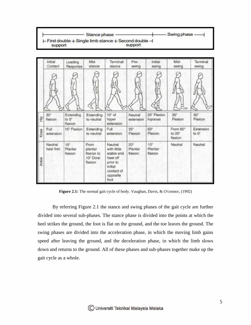
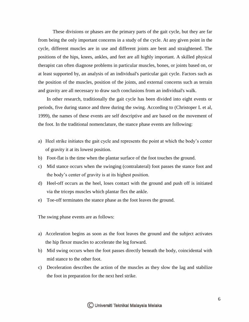
Figure 2.1: The normal gait cycle of body. Vaughan, Davis, & O'connor, (1992)
By referring Figure 2.1 the stance and swing phases of the gait cycle are further
divided into several sub-phases. The stance phase is divided into the points at which the
heel strikes the ground, the foot is flat on the ground, and the toe leaves the ground. The
swing phases are divided into the acceleration phase, in which the moving limb gains
speed after leaving the ground, and the deceleration phase, in which the limb slows
down and returns to the ground. All of these phases and sub-phases together make up the
gait cycle as a whole.
6
These divisions or phases are the primary parts of the gait cycle, but they are far
from being the only important concerns in a study of the cycle. At any given point in the
cycle, different muscles are in use and different joints are bent and straightened. The
positions of the hips, knees, ankles, and feet are all highly important. A skilled physical
therapist can often diagnose problems in particular muscles, bones, or joints based on, or
at least supported by, an analysis of an individual's particular gait cycle. Factors such as
the position of the muscles, position of the joints, and external concerns such as terrain
and gravity are all necessary to draw such conclusions from an individual's walk.
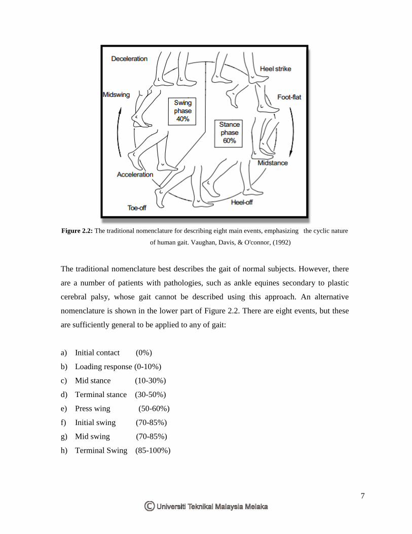
In other research, traditionally the gait cycle has been divided into eight events or
periods, five during stance and three during the swing. According to (Christoper L et al,
1999), the names of these events are self descriptive and are based on the movement of
the foot. In the traditional nomenclature, the stance phase events are following:
a) Heel strike initiates the gait cycle and represents the point at which the body’s center
of gravity it at its lowest position.
b) Foot-flat is the time when the plantar surface of the foot touches the ground.
c) Mid stance occurs when the swinging (contralateral) foot passes the stance foot and
the body’s center of gravity is at its highest position.
d) Heel-off occurs as the heel, loses contact with the ground and push off is initiated
via the triceps muscles which plantar flex the ankle.
e) Toe-off terminates the stance phase as the foot leaves the ground.
The swing phase events are as follows:
a) Acceleration begins as soon as the foot leaves the ground and the subject activates
the hip flexor muscles to accelerate the leg forward.
b) Mid swing occurs when the foot passes directly beneath the body, coincidental with
mid stance to the other foot.
c) Deceleration describes the action of the muscles as they slow the lag and stabilize
the foot in preparation for the next heel strike.
7
Figure 2.2: The traditional nomenclature for describing eight main events, emphasizing the cyclic nature
of human gait. Vaughan, Davis, & O'connor, (1992)
The traditional nomenclature best describes the gait of normal subjects. However, there
are a number of patients with pathologies, such as ankle equines secondary to plastic
cerebral palsy, whose gait cannot be described using this approach. An alternative
nomenclature is shown in the lower part of Figure 2.2. There are eight events, but these
are sufficiently general to be applied to any of gait:
a) Initial contact (0%)
b) Loading response (0-10%)
c) Mid stance (10-30%)
d) Terminal stance (30-50%)
e) Press wing (50-60%)
f) Initial swing (70-85%)
g) Mid swing (70-85%)
h) Terminal Swing (85-100%)
8
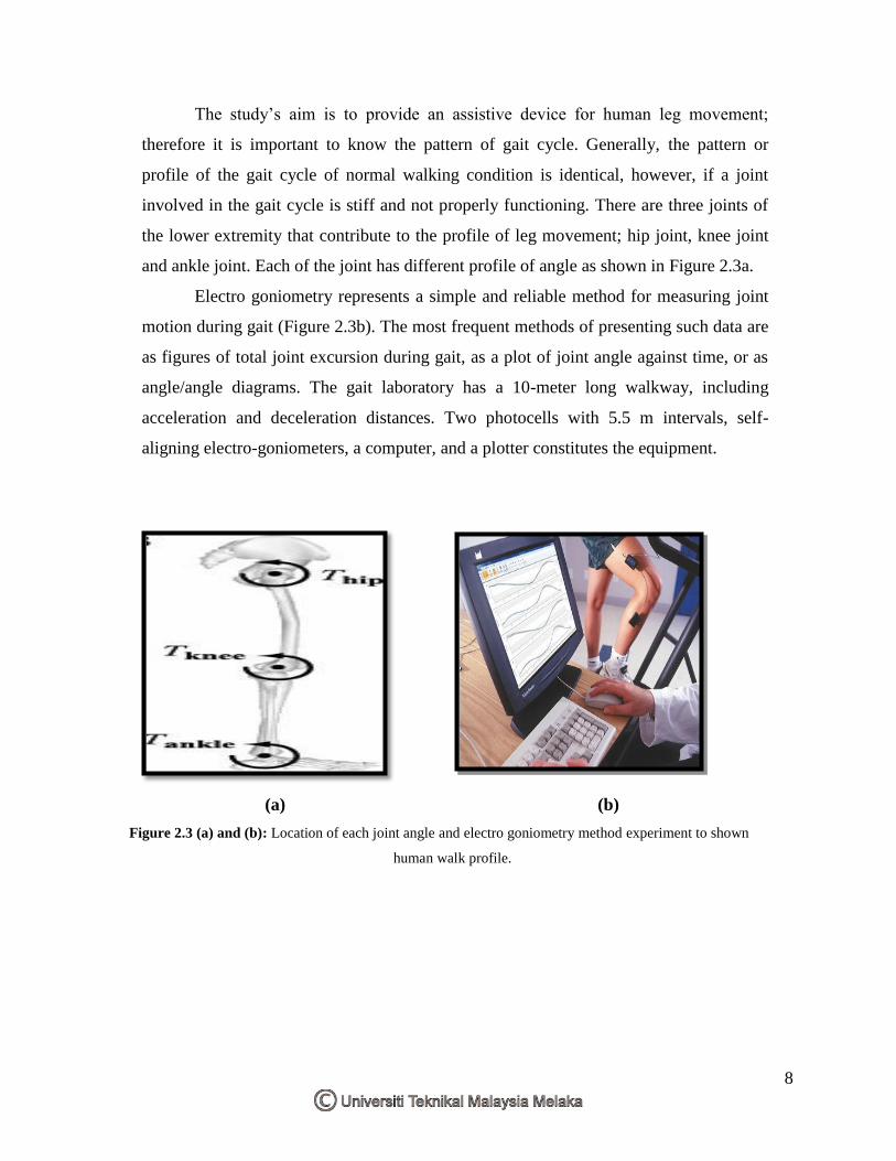
The study’s aim is to provide an assistive device for human leg movement;
therefore it is important to know the pattern of gait cycle. Generally, the pattern or
profile of the gait cycle of normal walking condition is identical, however, if a joint
involved in the gait cycle is stiff and not properly functioning. There are three joints of
the lower extremity that contribute to the profile of leg movement; hip joint, knee joint
and ankle joint. Each of the joint has different profile of angle as shown in Figure 2.3a.
Electro goniometry represents a simple and reliable method for measuring joint
motion during gait (Figure 2.3b). The most frequent methods of presenting such data are
as figures of total joint excursion during gait, as a plot of joint angle against time, or as
angle/angle diagrams. The gait laboratory has a 10-meter long walkway, including
acceleration and deceleration distances. Two photocells with 5.5 m intervals, self-
aligning electro-goniometers, a computer, and a plotter constitutes the equipment.
(a) (b)
Figure 2.3 (a) and (b): Location of each joint angle and electro goniometry method experiment to shown
human walk profile.
9
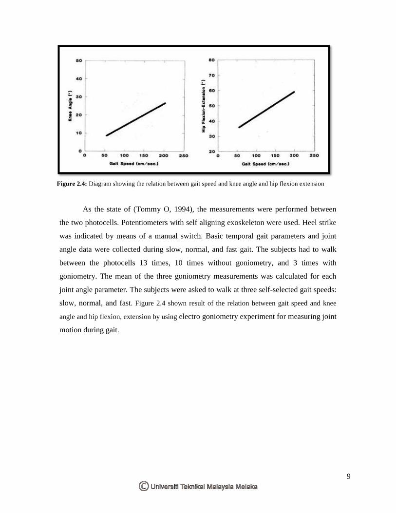
Figure 2.4: Diagram showing the relation between gait speed and knee angle and hip flexion extension
As the state of (Tommy O, 1994), the measurements were performed between
the two photocells. Potentiometers with self aligning exoskeleton were used. Heel strike
was indicated by means of a manual switch. Basic temporal gait parameters and joint
angle data were collected during slow, normal, and fast gait. The subjects had to walk
between the photocells 13 times, 10 times without goniometry, and 3 times with
goniometry. The mean of the three goniometry measurements was calculated for each
joint angle parameter. The subjects were asked to walk at three self-selected gait speeds:
slow, normal, and fast. Figure 2.4 shown result of the relation between gait speed and knee
angle and hip flexion, extension by using electro goniometry experiment for measuring joint
motion during gait.
10
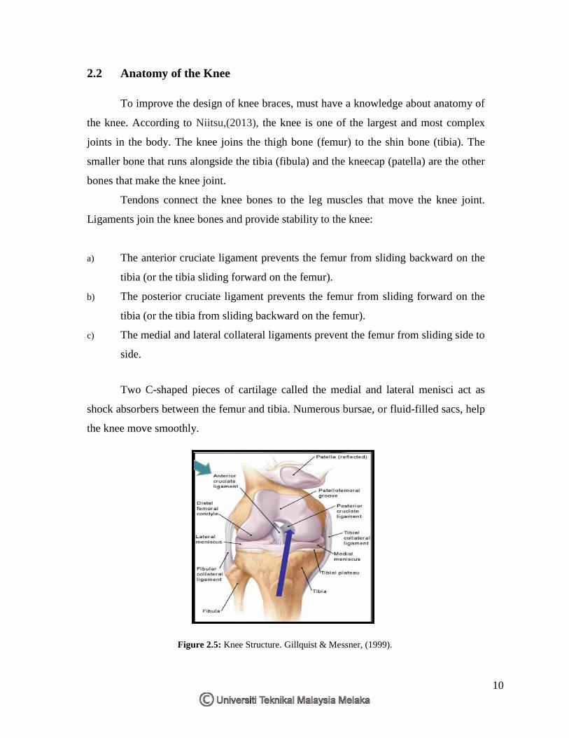
2.2 Anatomy of the Knee
To improve the design of knee braces, must have a knowledge about anatomy of
the knee. According to Niitsu,(2013), the knee is one of the largest and most complex
joints in the body. The knee joins the thigh bone (femur) to the shin bone (tibia). The
smaller bone that runs alongside the tibia (fibula) and the kneecap (patella) are the other
bones that make the knee joint.
Tendons connect the knee bones to the leg muscles that move the knee joint.
Ligaments join the knee bones and provide stability to the knee:
a) The anterior cruciate ligament prevents the femur from sliding backward on the
tibia (or the tibia sliding forward on the femur).
b) The posterior cruciate ligament prevents the femur from sliding forward on the
tibia (or the tibia from sliding backward on the femur).
c) The medial and lateral collateral ligaments prevent the femur from sliding side to
side.
Two C-shaped pieces of cartilage called the medial and lateral menisci act as
shock absorbers between the femur and tibia. Numerous bursae, or fluid-filled sacs, help
the knee move smoothly.
Figure 2.5: Knee Structure. Gillquist & Messner, (1999).
![Silpakorn Universitywebserv.cp.su.ac.th/lecturer/tasanawa/cs517321/... · 'jubjang' , 1150, [ ' comsci ' , 2911 9.98, (Tuples) ' Sati t', 70.2, square braces [ ] 70.2) ( ' comsci](https://img.pdfslide.tips/doc/110x75/5f7b02e61b1eaf063d0e2c14/silpakorn-jubjang-1150-comsci-2911-998-tuples-sati-t-702.jpg)