Embed Size (px)
Citation preview
UNIVERSITI TEKNIKAL MALAYSIA MELAKA
DEVELOPMENT OF MODULAR JIGS
AND FIXTURE FOR CATIA
Thesis submitted in accordance with the partial requirements of the
Universiti Teknikal Malaysia Melaka for the
Bachelor of Manufacturing Engineering (Process and System)
By
SOO WAI HONG
Faculty of Manufacturing Engineering APRIL 2007


DECRALATION
I hereby, declare this thesis entitled “Development of
Modular jig and Fixtures for CATIA” is the results of
my own research except as cited in the reference.
Signature : ………………………………………….
Author’s Name : SOO WAI HONG
Date : 9 MAY 2007
ii
ABSTRACT
The title of this project is Development of Modular Jig and Fixture for CATIA. The
purpose of carrying out this project is to investigate the development of modular jig
and fixture using the CATIA software. This project will enable students to increase
their knowledge on modular jig, fixture and also the CATIA software. In the initial
step of the project, many researches are done to gather information. After that, the
information is gathered to create the sketch drawing which is the basic before
designing the jig and fixture. When the design is ready, a library is added to the
CATIA software and also the assembly and testing process. If a problem occurred
during the testing process, the jig and fixture design is modified and re-tested until
the required result is obtained. Finally, discussion of the result obtained are stated
and some recommendations to help improve further research of the project. At the
end of the report, a conclusion is drawn out from the result obtained which states on
how good and further improvement that can be made for this project.
iii
ABSTRAK
Tajuk projek ini adalah Pembangunan ‘Modular Jig’ dan ‘Fixture’ dengan
mengunakan sistem CATIA. Objektif utama projek ini adalah untuk menyiasat
pembangunan ‘modular jig’ dan ‘fixture’ dengan menggunakan sistem CATIA.
Projek ini akan membantu para pelajar menambahkan pengetahuan mereka dalam
bidang ‘modular jig’, ‘fixture’ dan juga sistem CATIA. Pada peringkat awal projek
ini, banyak penyelidikan dijalankan untuk mengumpul data-data yang berkenaan
dengan projek ini. Selepas itu, data-data yang dikumpul itu akan digunakan dalam
proses rekabentuk ‘jig’ dan ‘fixture’. Apabila proses rekabentuk siap, cirri-ciri
seperti perpustakaan akan ditambah dalam sistem CATIA, penghimpunan dan juga
proses menguji. Jika terdapat sebarang masalah dalam proses menguji itu, proses
rekabentuk terpaksa diulang semula sehingga mendapat keputusan yang memuaskan.
Akhir sekali, analisis projek ini dibuat berdasarkan keputusan yang telah dicapai
dalam projek ini. Selain itu, sedikit cadangan juga dikemukakan bagi memudahkan
mereka yang ingin untuk meneruskan projek ini pada tahap yang lebih tinggi. Pada
akhir tesis ini, sebuah konklusi telah dibuat berdasarkan keputusan-keputusan yang
telah dicapai seperti kebaikan dan juga kajian selanjutnya bagi projek ini.
iv

ACKNOWLEDGMENTS
First and foremost, I would like to take this opportunity to express my utmost
gratitude to my project supervisor, Mr. Mohd Shahir Bin Kasim for his sincere
guidance and counsel throughout the course of accomplishing this project. He is
willing to share with me his knowledge in the field of my works and available for
discussion on the project all the time.
In here, I also need to Special thanks are extended to my friends, who have show
their knowledge and explain to me the function jig and fixture in CNC machine and
assisting me in overcoming the difficulties throughout the project.
Last but not least, I would like to express my appreciation and gratitude to my
parents for their understanding and continuous care of me during the course of the
project.
v
TABLE OF CONTENTS
Approval………………………………………………………………………………
Declaration……………………………………………………………………………
Abstract……………………………………………………………………………….
Abstrak …………………………………………………………………………….....
Acknowledgement …………………………………………………………………...
Table of Contents……………………………………………………………………..
List of Figures………………………………………………………………………...
i
ii
iii
iv
v
vi
x
1 INTRODUCTION……………………………………………………….. 1
1.1
1.2
1.3
1.4
1.5
Introduction…………………………………………………………...
Objectives…………………………………………………………….
Scope of Study………………………………………………………..
Problem Statement……………………………………………………
Thesis Outline………………………………………………………...
1
2
2
2
3
2 LITERATURES REVIEW……………………………………………. 4
2.1 Introduction Jig and Fixture…………………………………………. 4
2.1.1 Production Devices………………………………………………….. 5
2.2 Definition Jig and Fixture……………………………………………
1. Jig……………………………………………………………...
2. Clamp………………………………………………………….
3. Box…………………………………………………………….
4. Fixture…………………………………………………………
6
6
6
7
8
2.3 Description of The Fixture…………………………………………... 8
2.4
2.4.1
2.4.2
2.4.3
2.4.4
Element of Fixture……………………………………………………
Locators……………………………………………………………....
Clamp………………………………………………………………...
Supports………………………………………………………………
Fixture Body………………………………………………………….
9
9
10
10
11
vi
2.5
2.5.1
2.5.2
2.5.3
Fixture Design Fundamental…………………………………………
Fixture Design………………………………………………………..
Fixture Design Criteria……………………………………………….
Fixture Design Procedure…………………………………………….
11
11
13
13
2.6
2.6.1
2.6.2
2.6.3
2.6.4
Advantages of Jigs and Fixtures……………………………………..
Productivity…………………………………………………………..
Interchange ability……………………………………………………
Skill Reduction……………………………………………………….
Cost Reduction……………………………………………………….
14
14
15
15
15
2.7
2.7.1
2.7.2
2.7.3
Modular Jigs and Fixtures Components……………………………...
Subplate Systems…………………………………………………….
T-slot Systems………………………………………………………..
Dowel Pin Systems…………………………………………………..
16
16
17
17
2.8
2.8.1
2.8.2
2.8.3
System Components………………………………………………….
Locating Elements……………………………………………………
Clamping Elements…………………………………………………..
Tool Guiding and Setting Elements………………………………….
18
18
18
18
2.9
2.9.1
Modular Fixturing……………………………………………………
Applications for Modular Fixturing………………………………….
18
19
2.10 Computer Aided Design (CAD)……………………………………... 20
2.11 Computer Aided Manufacturing (CAM)……………………………. 20
2.12 Computer Numerical Control (CNC)………………………………... 21
2.13
2.13.1
2.13.2
2.13.3
2.13.5
What is CATIA………………………………………………………
CATIA for Jigs and Fixture………………………………………….
Benefit of CATIA V5 for Jigs and Fixtures………………………….
Mechanical Design (CATIA Software)……………………………...
Machining (CATIA Software)………………………………………
22
22
23
24
27
3 METHODOLOGY………………………………………………………. 28
3.1 Introduction………………………………………………………….. 29
3.2 Description of The Methodology……………………………………. 30
vii
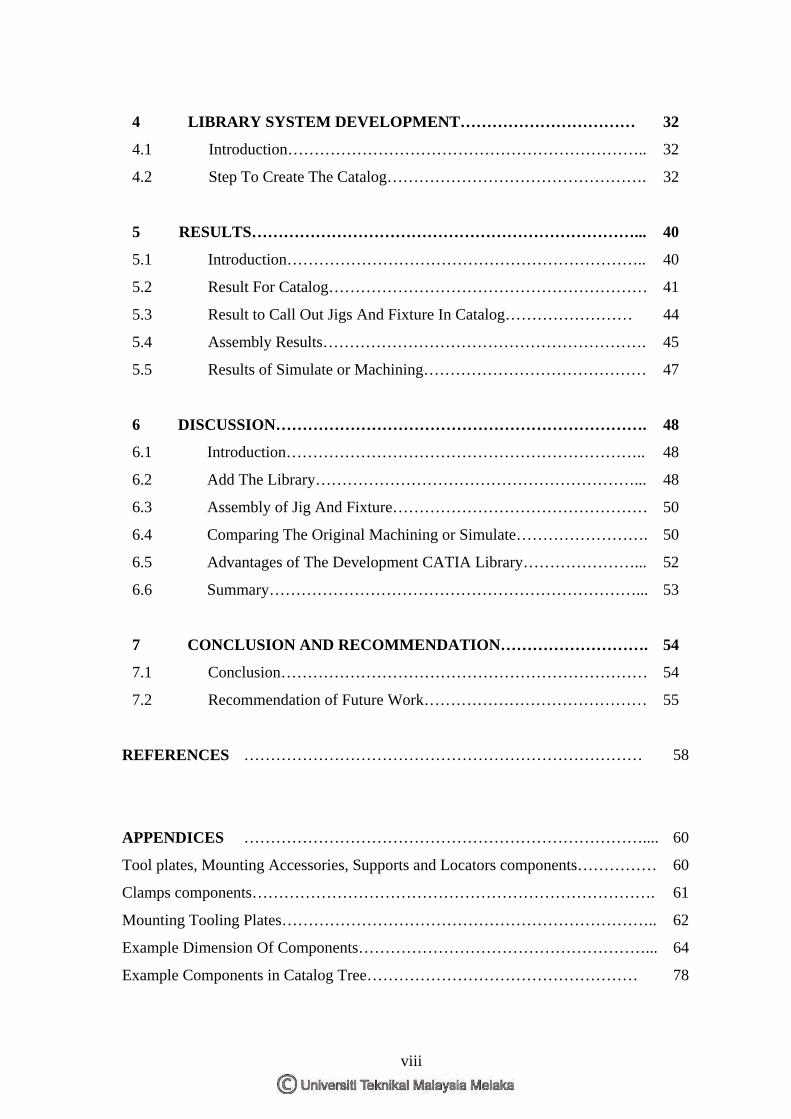
4 LIBRARY SYSTEM DEVELOPMENT…………………………… 32
4.1 Introduction………………………………………………………….. 32
4.2 Step To Create The Catalog…………………………………………. 32
5 RESULTS………………………………………………………………... 40
5.1 Introduction………………………………………………………….. 40
5.2 Result For Catalog…………………………………………………… 41
5.3 Result to Call Out Jigs And Fixture In Catalog…………………… 44
5.4 Assembly Results……………………………………………………. 45
5.5 Results of Simulate or Machining…………………………………… 47
6 DISCUSSION……………………………………………………………. 48
6.1 Introduction………………………………………………………….. 48
6.2 Add The Library……………………………………………………... 48
6.3 Assembly of Jig And Fixture………………………………………… 50
6.4 Comparing The Original Machining or Simulate……………………. 50
6.5 Advantages of The Development CATIA Library…………………... 52
6.6 Summary……………………………………………………………... 53
7 CONCLUSION AND RECOMMENDATION………………………. 54
7.1 Conclusion…………………………………………………………… 54
7.2 Recommendation of Future Work…………………………………… 55
REFERENCES ………………………………………………………………… 58
APPENDICES ………………………………………………………………….... 60
Tool plates, Mounting Accessories, Supports and Locators components…………… 60
Clamps components…………………………………………………………………. 61
Mounting Tooling Plates…………………………………………………………….. 62
Example Dimension Of Components………………………………………………... 64
Example Components in Catalog Tree…………………………………………… 78
viii
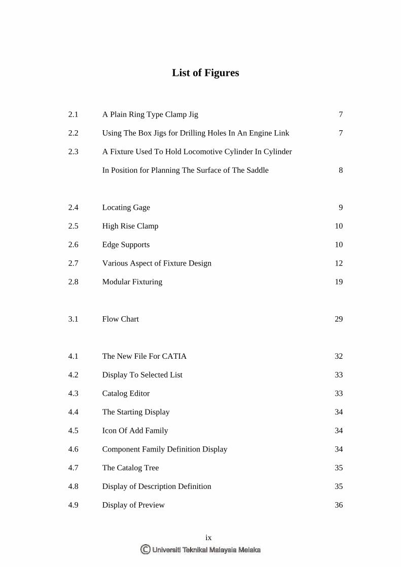
List of Figures
2.1
2.2
2.3
2.4
2.5
2.6
2.7
2.8
3.1
4.1
4.2
4.3
4.4
4.5
4.6
4.7
4.8
4.9
A Plain Ring Type Clamp Jig
Using The Box Jigs for Drilling Holes In An Engine Link
A Fixture Used To Hold Locomotive Cylinder In Cylinder
In Position for Planning The Surface of The Saddle
Locating Gage
High Rise Clamp
Edge Supports
Various Aspect of Fixture Design
Modular Fixturing
Flow Chart
The New File For CATIA
Display To Selected List
Catalog Editor
The Starting Display
Icon Of Add Family
Component Family Definition Display
The Catalog Tree
Display of Description Definition
Display of Preview
7
7
8
9
10
10
12
19
29
32
33
33
34
34
34
35
35
36
ix
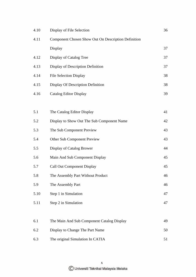
4.10
4.11
4.12
4.13
4.14
4.15
4.16
5.1
5.2
5.3
5.4
5.5
5.6
5.7
5.8
5.9
5.10
5.11
6.1
6.2
6.3
Display of File Selection
Component Chosen Show Out On Description Definition
Display
Display of Catalog Tree
Display of Description Definition
File Selection Display
Display Of Description Definition
Catalog Editor Display
The Catalog Editor Display
Display to Show Out The Sub Component Name
The Sub Component Preview
Other Sub Component Preview
Display of Catalog Brower
Main And Sub Component Display
Call Out Component Display
The Assembly Part Without Product
The Assembly Part
Step 1 in Simulation
Step 2 in Simulation
The Main And Sub Component Catalog Display
Display to Change The Part Name
The original Simulation In CATIA
36
37
37
37
38
38
39
41
42
43
43
44
45
45
46
46
47
47
49
50
51
x
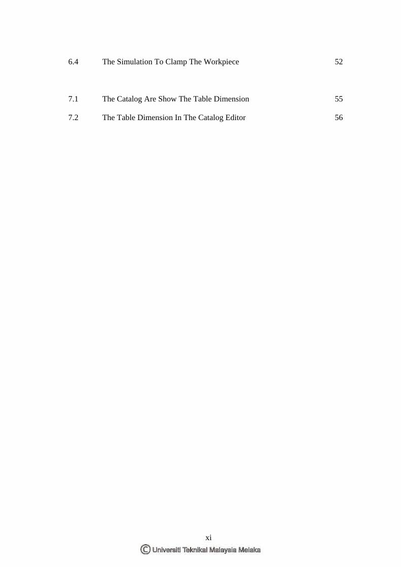
6.4
7.1
7.2
The Simulation To Clamp The Workpiece
The Catalog Are Show The Table Dimension
The Table Dimension In The Catalog Editor
52
55
56
xi
CHAPTER 1 INTRODUCTION
1.1 Introduction
In the new millennium, technology is most important in industry. Therefore it
is imperative that new technologies to be deployed to leverage the current situation.
Priority is given to maximization of the current non renewable technology supply to
satisfy demand of economic; on the other hand exploring new possibility on vastly
untapped resources especially on areas of renewable technology sources such as
machining.
Recently, technology issues have brought back a classical technology to the attention
of scientific and engineering community; CNC machine promises great to produce
product and also can save time. Despite industry in any country also to used the CNC
machine. In fact, CNC machine need the software and program to control it. So
before the CNC machine to run the product the engineers need to use the software to
draw the product drawing and also write the program. This is called the CAD and
CAM The software likes Solid Work, CATIA, AutoCAD and so on. Jigs and fixture
also important in CNC machining, it not only save the cost and time also can to get
the CNC machine easily to simulate. In this project is developing the modular jigs
and fixtures for CATIA. CATIA software is a excellent and widely to use. The
software not only can do the CAD but also can do the CAM.
1
1.2 Objectives
1. To understand modular jigs and fixture application.
2. To understand design fixturing system on CNC machine.
3. To apply CAD software in designing fixturing systems.
4. To simulate and validate to ensure the accuracy of the finished model.
5. This analyses the benefit of implementation.
1.3 Scope of Study
This project will involve design and developing modular fixturing system for
CNC machine using CATIA software. And also add the component of the clamping
in the CATIA library. This development is to simulate easily and also solve the
programming when sent to the CNC machine. In the project, firstly, study on the
theoretical of the jig and fixture. After that, going to learning the cad and cam system.
Form there, comparison may be made with the information to design the jig and
fixture.
1.4 Problem Statement
Manufacturers are faced with an increasing demanding market. Lead times
are getting shorter and customers are calling for sophisticated products. Fierce
competition is marking it harder to win new customers and keep their loyalty. In
addition, industry pressure continues to build, with a growing need for standards
compliance, and an inescapable reliance on suppliers. To meet the challenges of
today market, manufacturers and supplier must deliver high quality products in less
time, while driving costs down and improving their design processes. One major
opportunity to reduce time to market is by improving tooling design of critical jigs
and fixtures. The traditional 3D solutions having limitation in standardization of
components, preventing their reuse in future designs and increasing design time. Due
2
to extensive design jig and fixture which is wasting time and facing of creating
mistakes. This project was proposed to give solution of these problems. Until now,
many cad software not have library, if have also not many. So this project is
development jig and fixture and also browses to library. This is to get easy because
some standard components no need to draw also can get in library.
1.5 Thesis Outline
Thesis outline is a summary of every chapter was described to introduce
about the chapter. Chapter one (1) introduced about the basic theory, problem
encounter, and the content of the thesis and also the main objective of doing the
thesis. Then go to the chapter two (2) where all information about jig and fixture, the
CATIA software, CAD and CAM system and also CNC machine are covered. With
good references, an overview comprising history, classification and applications
progressively introduce the idea behind the technology. Then is chapter three (3),
methodology is to inform the process flow. After that, is chapter four (4) will
perform how to create the catalog. The phase of design will show in this chapter.
Then go to the chapter five (5), where the results from modular jig and fixture design
will performed and assembly the product with jig and fixture by using CATIA.
Besides that, also show the simulation. It includes summary of research form this
project. The chapter six (6) is to discuss the problem for the project and the
advantages of this development and the chapter seven (7) is recommendation and
conclusion will explain in the end of this chapter.
3
CHAPTER 2 LITERATURE REVIEW
2.1 Introduction Jig and Fixture
Today, jig and fixtures are devices used to facilitate production work,
making interchangeable pieces of work possible at a saving in cost of production.
Both terms are frequently used incorrectly in shops. Jig is a guiding device and a
fixture is a holding device. Jig and fixtures are used to locate and hold the work that
is to be machined [1]. These devices are provided with attachments for guiding,
setting, and supporting the tools in such a manner that all the workpiece produced in
given jig or fixture will be exactly a like in every way.
Fixtures are important in both traditional manufacturing and modern flexible
manufacturing system (FMS), which directly affect manufacturing quality,
productivity, and cost of product. The time spent on designing and fabricating
fixtures significantly contributes to the production cycle in improving current
products and developing new ones [16]. Therefore, much attention has been paid to
the study of fixturing in manufacturing.
Flexible fituring becomes necessary in FMS and computer-intergrated manufacturing
system (CIMS). In FMS or CIMS, machine tools ( and other equipment) are flexible
for fabrication, assembly, and treatment. They are controlled by computer and linked
by a material handling system to move parts from one workstation to another [16].
4
The fixtures employed in FMS must be adaptable in order to accommodate the wide
variety of parts, thus achieving true flexibility.
The employment of unskilled labor is possible when jigs and fixtures can be used in
production work [1]. Also, the use of these devices can result in such a degree of
accuracy that workpieces can be assembled with a minimum amount of fitting.
A jig or fixtures can be designed for a particular job. The form to be used depends on
the shape and requirement of the workpiece to be machined.
2.1.1 Production Devices
Production devices are generally workholders with or without tool or guiding
or setting arrangement. These are called jigs and fixtures.
Jigs are provided with tool guiding elements such as drill bushes. These direct the
tool to the correct position on the workpiece [6]. Jigs are rarely clamped on the
machine table because it is necessary to move the jig on the table to align the various
bushes in the jigs with the machine spindle.
Fixtures hold the workpiece securely in the correct position with respect to the
machine or cutter during operation [6]. These is sometimes a provision in the fixture
for setting the tool with respect to the workpiece or fixture, but the tool is not guided
as in a jig. Fixtures are often clamped to the machine table.
5
2.2 Definition Jig and Fixture
Jigs and fixtures are devices used to locate and hold the work that is to be machined.
There are generally two types of jigs used: the clamp jig and the box jig. A fixture
anchors the workpiece firmly in place for the machining operation, but it does not
form a guide for the tool. It is sometimes difficult to differentiate between a jig and a
fixture
1. Jig
Jig may be defined as the device which holds and positions the workplace,
locates or guides the cutting tool related to the workplace and usually is not fixed on
the machine table [7]. Basically, jig can use in any machine for example CNC
machine, drilling machine, milling machine and so on.
2. Clamp Jig
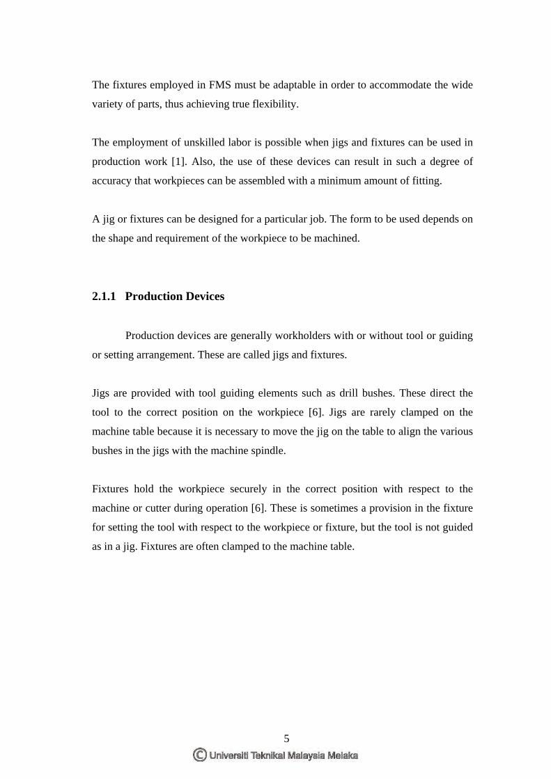
This jig device it’s name from the fact that it usually resembles some form of
clamp. It’s adapted for use on the workpieces on which that axes of all the holes that
are to be drilled are parallel. Clamp jig are sometimes called open jigs. A simple
example of a clamp jigs is design for drilling holes that are all the same size. For
example: the study holes in cylinder head (Figure 2.1) [7]. The jig consists of a ring
with four lugs for clamping and is frequently called a ring jig .it is attached to the
cylinder head and held by U-bolt clamps. When used as a guide for the drill in the
drilling operation, the jig makes certain that the holes are in the correct locations
because the holes in the jig were located originally with precision.
6
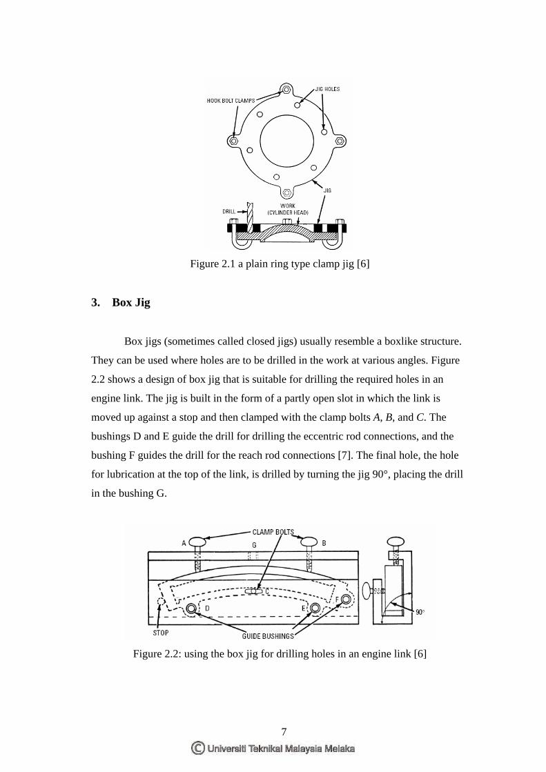
Figure 2.1 a plain ring type clamp jig [6]
3. Box Jig
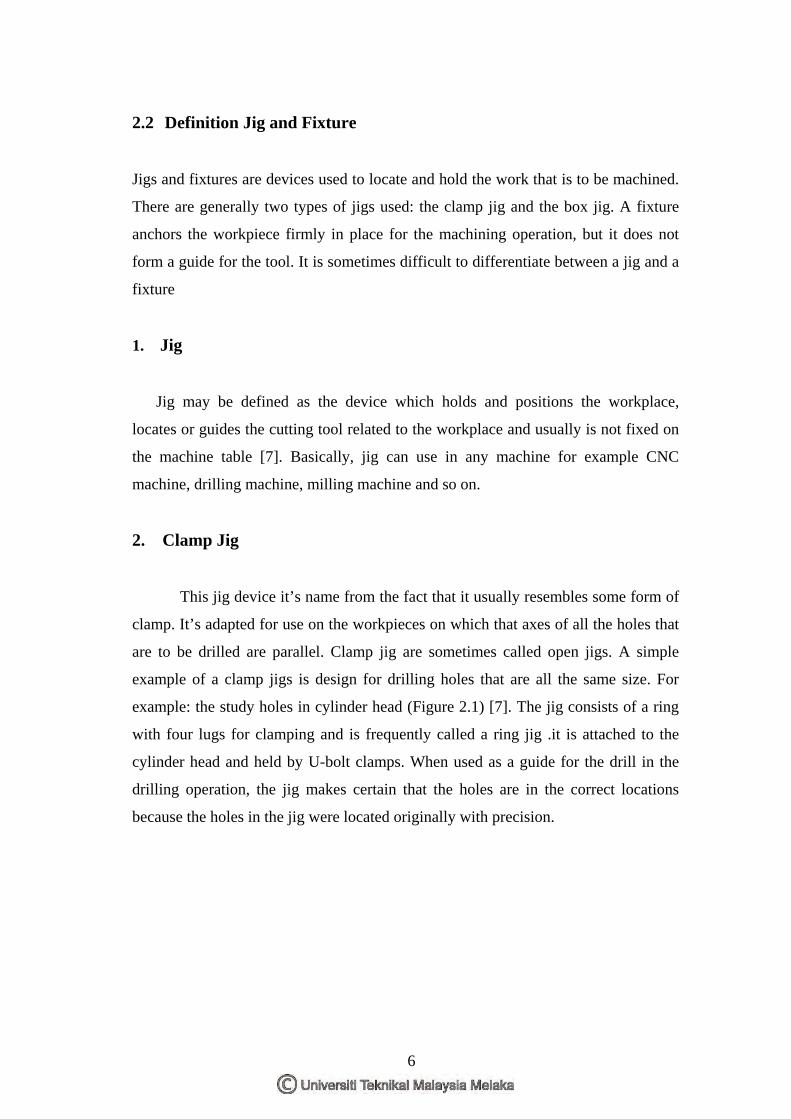
Box jigs (sometimes called closed jigs) usually resemble a boxlike structure.
They can be used where holes are to be drilled in the work at various angles. Figure
2.2 shows a design of box jig that is suitable for drilling the required holes in an
engine link. The jig is built in the form of a partly open slot in which the link is
moved up against a stop and then clamped with the clamp bolts A, B, and C. The
bushings D and E guide the drill for drilling the eccentric rod connections, and the
bushing F guides the drill for the reach rod connections [7]. The final hole, the hole
for lubrication at the top of the link, is drilled by turning the jig 90°, placing the drill
in the bushing G.
Figure 2.2: using the box jig for drilling holes in an engine link [6]
7
4. Fixture
A fixture is a work holding device which on the holds and positions the
workplace, but does not itself guide locate or positions the cutting tool [7]. It is
sometimes difficult to differentiate between a jig and a fixture, since their basic
functions can overlap in the more complicated designs. The best means of
differentiating between the two devices is to apply the basic definitions, as follows:
• The jig is a guiding device.
• The fixture is a holding device
Figure 2.3: A fixture used to hold locomotive cylinders in position for planing the surfaces of the saddles.[6]
2.3 Description Of The Fixture
A fixture is a device for locating, holding and supporting a workpiece during
a manufacturing operation. Fixtures are essential elements of production processes as
they are required in most of the automated manufacturing, inspection, and assembly
operations [2].
Fixtures must correctly locate a workpiece in a given orientation with respect
to a cutting tool or measuring device, or with respect to another component, as for
instance in assembly or welding. Such location must be invariant in the sense that the
8
devices must clamp and secure the workpiece in that location for the particular
processing operation.
There are many standard work holding devices such as jaw chucks, machine vises,
drill chucks, collets, etc. which are widely used in workshops and are usually kept in
stock for general applications [2]. Fixtures are normally designed for a definite
operation to process a specific workpiece and are designed and manufactured
individually. Jigs are similar to fixtures, but they not only locate and hold the part but
also guide the cutting tools in drilling and boring operations. These work holding
devices are collectively known as jigs and fixtures.
2.4 Elements of Fixtures
Generally, all fixtures consist of the following elements. Actually fixtures also are to
hold the workpiece when running the machining. Their have 3 examples such as
locator, clamp and supports. These 3 elements will explain as below:
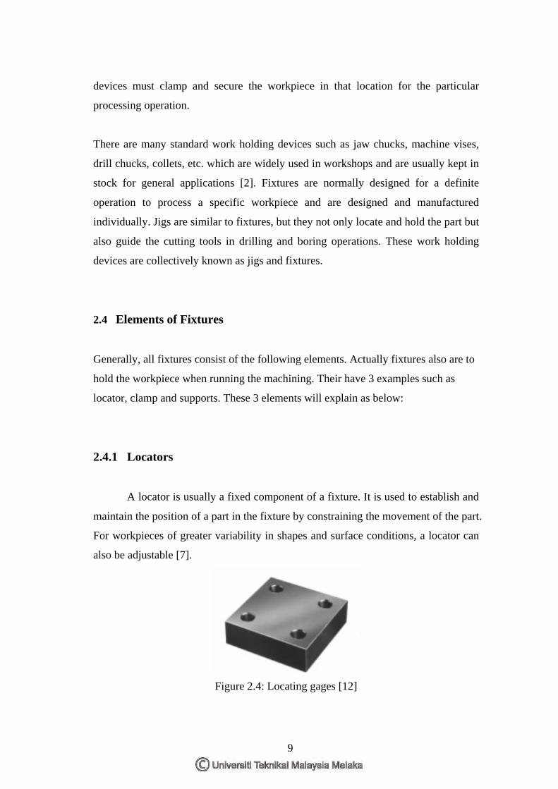
2.4.1 Locators
A locator is usually a fixed component of a fixture. It is used to establish and
maintain the position of a part in the fixture by constraining the movement of the part.
For workpieces of greater variability in shapes and surface conditions, a locator can
also be adjustable [7].
Figure 2.4: Locating gages [12]
9
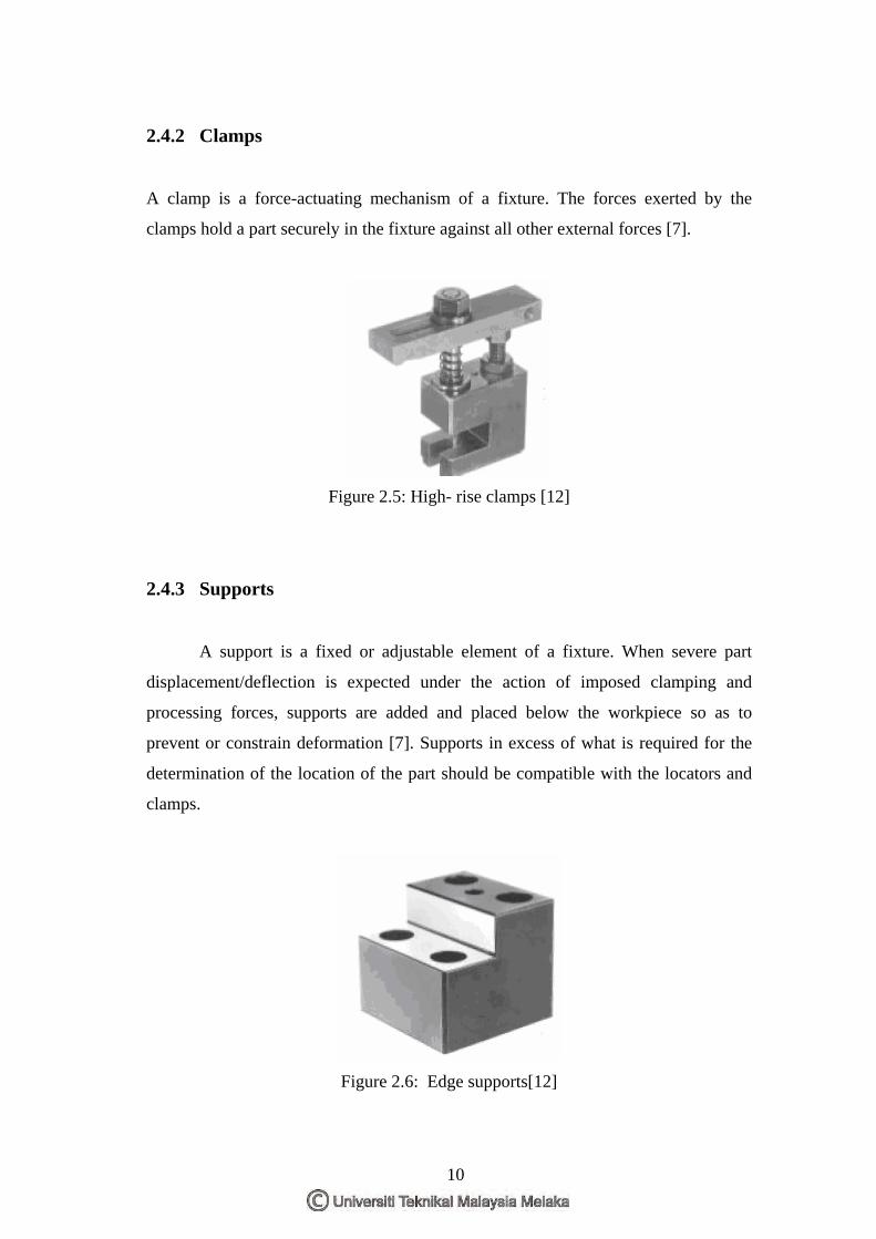
2.4.2 Clamps
A clamp is a force-actuating mechanism of a fixture. The forces exerted by the
clamps hold a part securely in the fixture against all other external forces [7].
Figure 2.5: High- rise clamps [12]
2.4.3 Supports
A support is a fixed or adjustable element of a fixture. When severe part
displacement/deflection is expected under the action of imposed clamping and
processing forces, supports are added and placed below the workpiece so as to
prevent or constrain deformation [7]. Supports in excess of what is required for the
determination of the location of the part should be compatible with the locators and
clamps.
Figure 2.6: Edge supports[12]
10

2.4.4 Fixture Body
Fixture body, or tool body, is the major structural element of a fixture. It
maintains the spatial relationship between the fixturing elements mentioned above,
locators, clamps, supports, and the machine tool on which the part is to be processed.
2.5 Fixture Design Fundamental
Fixture design consists of a number of distinct activities: fixture planning,
fixture layout design, fixture element design, tool body design, etc. They are listed in
Figure 1.4 in their natural sequence, although they may be developed in parallel and
not necessarily as a series of isolated activities in actual execution [2]. Fixture design
deals with the establishment of the basic fixture concepts:
• Fixture layout is an embodiment of the concepts in the form of a spatial
configuration of the fixture
• Fixture element design is concerned with the concrete details of the locators,
clamps and supports
• Tool body design produces a structure combining the fixture elements in the
desired spatial relationship with the machine tool.
2.5.1 Fixture Design
Fixture planning is to conceptualize a basic fixture configuration through
analyzing all he available information regarding the material and geometry of the
workpiece, operations required, processing equipment for the operations, and the
operator [2]. The following outputs included in the fixture plan:
• Fixture and complexity
• Number of per workpieces fixture
11


![Q] - Universiti Teknikal Malaysia Melakaeprints.utem.edu.my/8395/1/Quality_Study_Of_Parts_Produced_By_3D...disertasi bagi pengajian secara kerja kursus dan penyelidikan, atau Laporan](https://img.pdfslide.tips/doc/110x75/5cac70ea88c99358488c432d/q-universiti-teknikal-malaysia-bagi-pengajian-secara-kerja-kursus-dan-penyelidikan.jpg)