Embed Size (px)
Citation preview

UPJC FILE CORY
AFWAL-TR-87-3008VOLUMEI L
SUPERPLASTIC FORMED ALUMINUM AIRFRAME STRUCTURESVOLUME I- EXECUTIVE SUMMARY
M. M. RATWANIo R. VASTAVAH. R. ZAMANI
o S. P. AGRAWAL L.
Tý NORTHROP CORPORATION - AIRCRAFT DIVISIONO) HAWTHORNE, CALIFORNIA 90250-3277
JULY 1987FINAL REPORT FOR PERIOD NOVEMBER 1981 - JULY 1986
Approved for public release; distribution unlimited LYTC• ELECTE.
••,DEC 0 9 1988 j-
FLIGHT DYNAMICS LABORATORYAIR FORCE WRIGHT AERONAUTICAL LABORATORIESAIR FORCE SYSTEMS COMMANDWRIGHT-PATTERSON AIR FORCE BASE, OHIO 45433-6553
I I~
NOTICE
When Government drawings, specifications, or other data are used for any purposeother than in connection with a definitely related Government procurement operation,the United States Government thereby incurs no responsibility nor any obligationwhatsoever; and the fact that the government may have formulated, furnished, or inany way supplied the said drawings, specifications, or other data, is not to be re-garded by implication or otherwise as in any manner licensing the holder or anyother person or corporation, or conveying any rights or permission to manufactureuse, or sell any patented invention that may in any way be related thereto.
This report has been reviewed by the Office of Public Affairs (ASD/PA) and isreleasable to the National Technical Information Service (NTIS). At NTIS, it willbe available to the general public, including foreign nations.
This tec-iical report has been reviewed and is approved for publication.
Larry G./e~ly, Chief /' Richard L. Rolfes, Projp t EngineerStructural Concepts Branch Structural Concepts BranchS.tructures Divison Structures Divison
FOR THE COMMANDER
Sre D t onel, USAFChief, Structures Divison
"If your address has changed, if you wish to be removed from our mailing list, orif the addressee is no longer employed by your organization please notify AFWAL/FIBC,f -PAFB, OH 45433 to help us maintain a current mailing list".
Copies oil this report should not be returned unless return is required by securityco.nisaderations, contractual obligations, or notice on a specific document.
UNCLASSIFIED-SECURITY CLASSIFICATION' OF THOS PACE
REPORT DOCUMENTATION PAGE
ia. REPORT SECURITY CLASSIFICATION lb. RESTRICTIVE MARKINGS
UNCI.ASSIFIED _
2e. SECURITY CLASSIFICATION AUTHORITY 3. OISTRIBUTION/AVAILABILITY OF REPORT
"- ...... ... Approved for nub]lic release; distribution2b. DECLASSIFICATIONDOWNGRADiNG SCHEDULE
unlimited.
4. PERFORMING ORGANIZATION REPORT NUMBER(S) 5. MONITORING ORGANIZATION REPORT NUMBER(S)
NOR 86-204 AFWAL-TR-87-3008, Volume I
6a. NAME OF PERFORMING ORGANIZATION bb. OFFICE SYMBOL 7t. NAME OF MONITORING ORGANIZATIO0
NORTHROP CORPORATION (I'appUicble) AIR FORCE WRIGHT AERONAUTICAL LABORATORIESAircraft Division Flight Dynamics Laboratory, AFWAL/FIBCB
6c. ADDRESS (City. State and ZIP Code) 7b. ADDRESS (City. State and ZIP Code)
One Northrop Avenue Wright-Patterson AFB, Ohio 45433-6553Hawthorne, California 90250
BS. NAME OF FUNDING/SPONSORING 8b. OFFICE SYMBOL 9. PROCUREMENT INSTRUMENT IDENTIFICATION NUMBER
ORGANIZATION Air Force Wright- (it applicable)
Aeronautical Laboratories AFWAL/FIBCB F33615-81-C-3227
Sc. ADOoRESS (City. State ad ZIP Code) 10. SOURCE OF FUNDING NOS.Wright-Patterson Air Force Base PROGRAM PROJECT TASK WORK UNIT
Ohio 45433-b553 ELEMENT NO. NO. NO. NO.
11. TITLE fl.elld. Seca..;l Clwficato., 62201F 2401 03 56
SEE REVERSE SIDE12. PERSONAL AUTHOR(l)
M. Ratwani, R. Vastava, H. Zamani, and S. P. Agrawal13.. TYPE OF REPORT 13b. TIME COVERED 14. DATE OF REPORT (Yr.. Mo.. Day) 115. PAGE COUNT
FINAL FROMLai_, TOj07!.. 1987 JULY 7916. SUPPLEMENTARY NOTATION
17. COSATI CODES 18. SUBJECT TERMS (Con tinue on reverse if neceuary and identify hy block 1'umber)
FIELD GROUP SUB. GR.
ABSTRACT (Continue on reverse i( necesary and identify by block number)
h his report summarizes the work done on Contract F33615-81-C-3227, "Superplastic FormedAluminum Airframe Structures." The scope of this program was to select, design, fabricate,evaluate, and test superplastically formed (SPF) aluminum airframe Parts. The program wasconducted in the following five tasks:
In Task I several candidate structural components were evaluated for SPF production design,and two parts, namely, Leading Edge Extension (LEX) and avionics deck compartment, showingthe most benefits from SPF, were selected.
Task !I dealt with selection of suitable alloy for fabrication of st.ructural components.After a detailed evaluation, Reynold's aluminum alloy MD254 was selected for part fabrication. (
(Continued)20. DISTRIBUTION/AVAILABI LITY OF ABSTRACT 21. ABSTRACT SECURITY CLASSIFICATION
UNCLA$SIFIED/UNLIMIrTEO 0 SAME AS APT. kDTIC USERS Q. UNCLASSIFIED
22a. NAME OF RESPONSIBLE INDIVIDUAL 22b. TELEPHONE NUMBER 22c. OFFICE SYMBOL
(Include Arva Code)R. Rolfes (513) 255-2521 1 AFWAL/FIBCB
DD FORM 1473, 83 APR EO;TION OF 1 JAN 73 IS OSSOLETE. UNiCLASSIFIEDSECURITY CLASSIFICATION OF THIS PAGE
,A
- .~. --
UNCLASSIFIEDiCURITY CLASSIFICATION OF TillS PAGE
11, Superplastic Vormed Aluminum Airtrame Structures (Executive), Volume I
19. ABSTRACT (Continued)
In Task 11I, subcomponents, which represented the most severe forming areas of each com-ponent were fabricated and tested. The selected subcomponents represented the criticalforming areas of the full-scale components.
Task IV involved fabricating and assembling the avionic:; deck. Tn addition, corrugationsfor the LEX were superplastically formed.
Part evaluation and structural verification were carried out in Task V. Structural verifi-cation involved static and fatigue tests of the avionics deck compartment.
The studies carried out in this program have shown that complex aluminum structural partscan be superplastically formed, resulting in substantial cost and weight savings.
Accession For'NTIS GRA&I
DTIC TABUnannounoad QJustifloatlon
Distribution/
Availability Codes
Avali and/or* !Dst special
SPEC*TE6
UNCLASSIFI ED
SECURITY CLASSIFICATION OF THIS PAGE

PREFACE
This report was prepared by the Northrop Corporation,
Aircraft Division, Hawthorne, California, coraring work doneunder the United States Air Force Contract F33615-81-C-3227
between November 1981 and July 1986. The contract was admini-
stered by the Air Force Wright Aeronautical Laboratories, Flight
Dynamics Laboratory, Wright-Patterson Air Force Base, Ohio. Mr.J. Tuss was the AFWAL/FIBCB Project Engineer from November 1981to November 1985 and Mr. R. Rolfes from November 1985 to July
1986.
The work was performed in the Northrop Advanced Struc-
tural Concepts Department under the program management of Mr. L.
Bernhardt from November 1981 to July 1984 and Dr. M. M. Ratwani
from August 1984 to July 1986. Mr. H. Zamani was the PrincipalInvestigator on this program. The following Northrop personnel
were the major contributors to the program:
DESIGN: L. Bernhardt & E. Youm
ANALYSIS: H. Zamani & J. Spradley
MATERIALS EVALUATIONS: S. P. Agrawal
FABRICATION OF SPF PARTS: R. Vastava, J. Akana and
J. Fabre
MANUFACTURING COORDINATION: S. Cormany & J. Wilkes
DOCUMENTATION: K. Gonzalez & K. Clayton
iii
.1.
LEFT INTENTIONALLY BLANK
iv
TABLE OF CONTEM
1 IN m IumON . . . . . . .
1.1 Background .. . . .. . .. . .. 21.2 Objective. . . . . . . . . . . . . . 21.3 Scope. ................. 3
2 PARP SELECTION AND DESIGN ................. 5
2.1 Parts Selection. . . . . . . . . . .5
2.1.1 Conoepbtal Design studies ....... . 52.1.2 Piece Oumt Reduction .... .... . 111.1,3 ..facturing Hrs timtes.. 142.1.4 . . . . . . .. . . . . . .R. 142. 1.5 Reoonmend•cioms ................. 18
2.2 Components Design and Analysis ............. 19
2.2.1 Avionics Deck ... ..... ....... . 92.2.2 Leading Edge Extension(LMC).......... 22
3 ATERIAL SELECTION AND EVAI= ON ............. 25
3.1 Material Screening . . . . . . . . ................. 253.2 Material Selection ................. . . .. .. 27
3.2.1 Microstructural Evaluation . ......... 273.2.2 Cone Tests ................... 28
3.3 Material Evaluation .................. 32
3.3.1 Cavitation Behavior of 7475 Alloy .... . 333.3.2 Mill Produced Versus Laboratory Material . 343.3.3 Tensile Tests ........ ...... 343.3.4 Caiipression Tests.....*..................343.3.5 Bearing Test,.. ................ 343.3.6 Shear-Punch Tests .............. 353.3.7 Stress-Corrosion Tests. ..... 353.3.8 EWfoliation Corrosion Tests . ....... 353.3.9 Fatigue Crack Growth Tests in Air... . 35
V

TABLE OF IITS (Ootinued)
PAGE
3.3.10 Anodizing Tests . . . . . . .......... 363.3.11 Painting Tests ..... ................. ... 363.3.12 Chem Milling Tests . . . . . . 36
3.3.12.1 Chm Milling Rate ........... 363.3.12.2 Fatigue Tests .. ............ 36
3.3.13 Adhesive Bonding Tests. ............. 373.3.14 Lap Shear Tests ......... ................ 37j.3.15 Clinbing Drum Peýel Tests ...... .. . 373.3.16 Resistance Seam Welding Tests ........... ... 383.3.17 Weldbondirn Tests . . . . . . . . . . . ... 38
3.4 Material Substitution to MD254 .. ...... 38
4 ~~)tUPR IBu t FOi G TESTS ..... * ........ ........ 43
4.1 Leading Bdge Extension Producibility Forming Tests . . 434.2 Avionics Deck PLoducibility Fondhng Tests. ........... 44.3 QCmpct Modifications. . . . . . . . . . . .. . 51
5 PARtS FARICATRION, ASSý4BLY AND TETING . . . . . . . . . . 53
5.1 Leading e teion (TM) ............... 535.2 Avionics Deck. . . . . . . . . ................. .. 54
5.2.1 Fabrication of Outer and Inner Skins. ...... 545.2.2 Waffle Pan Fabrication ................. ... 54
5.3 Deck Assembly. . . . . . . . . . . . . . . . . . . . . 625.4 Avionics Deck Testing . . . . . . . .. .............. . . . 62
5.4.1 Test Load Generation ................ . . 695.4.2 Test Setup........... . . ..................... 715.4.3 Static Testing ..... ................. ... 725.4.4 Fatigue Testing . ............. . . . ... 74
6 SUMMARY AND OCNC.JSIONS . . . . . ................. . .. 77
6.1 Sxtny .......... ....................... ... 776.2 Conclusions........ . . ...... ...................... 78
7 REFERENCES 79........ . . . .. . . .................... 79
vi
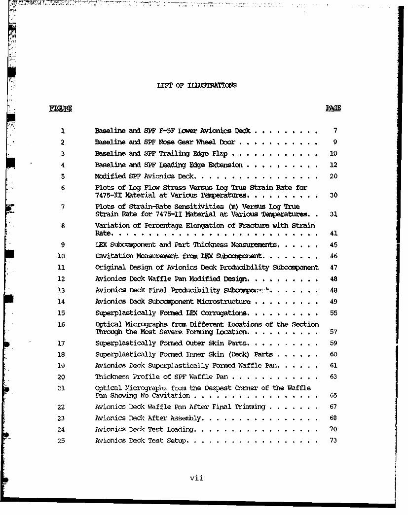
A4iLIST OF ILWSTRATONS
PAGE
1 Baseline and SPF F-5F Iawer Avionics Deck . . . . . . . . 7
2 Baseline and SPF Nose Gear Wheel Door. . .... . . ... 9
3 Baseline and SPF Trailing Edge Flap ... ... .. ... . 10
4 Baseline and SPF Leading•Edge Extension . .. ..... . 12
5 Modified SPF Avioni Deck ...... ............. 20
6 Plots of Log Flow Stress Versus Log True Strain Rate for7475-11 Material at Various Temperatures. . . . . . . . . . 30
7 Plots of Strain-Rate Sensitivities (in) Versus Log TrueStrain Rate for 7475-II Material at Various Temperatures.. 31
8 Variation of Percentage Elongation of Fracture with StrainRate .. . . . . . . .a t. o . . .. . . . . . . . . . . 41
9 LEX Subccm)onent and Part Thickness Measurewnts. . . 45
3i0 Cavitation Measurement from I=C Subompornent. . . . . . . . 46
11 Original Design of Avionics Deck Producibility Subcoopwnent 47
12 Avionics Deck Waffle Pan Mxoified Design .......... 48
13 Avionics Deck Final Producibility Submpw?:'-t. . . . . . . 48
14 Avionics Deck Suroanpoent Microstructure . . . . . . . . . 49
15 Supexplastically Formed LEX Corrugations . . . . . . . . . 55
16 Optical Micrographs from Different Locations of the SectionThrough the Most Severe Forning Location. . . . . . . . . . 57
17 Superplastically Formed Outer Skin Parts. . . . . 59
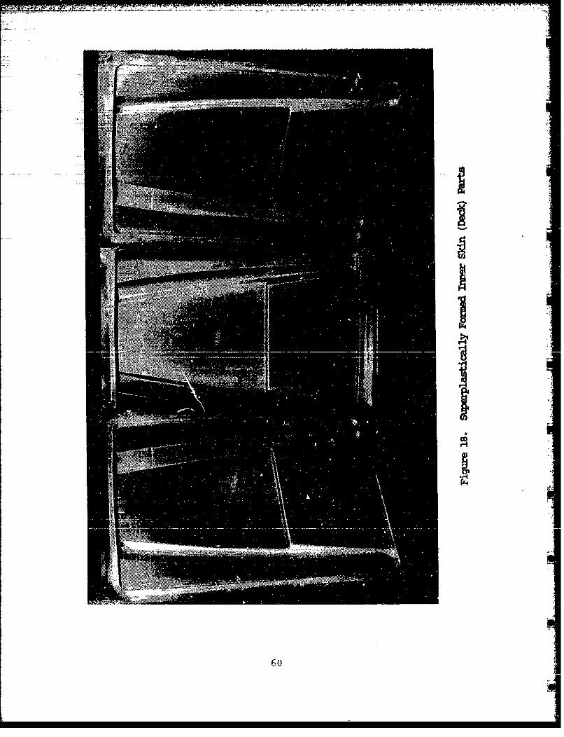
18 Superplastically Formed Inmer Skin (Deck) Parts . . . .. 60
19 Avionics Deck Suiperplastically Forsied Waffle Pan. . . . . . 61
20 Thicknes. Profile of SPF Waffle Pan.. . .. . . . .. . . 63
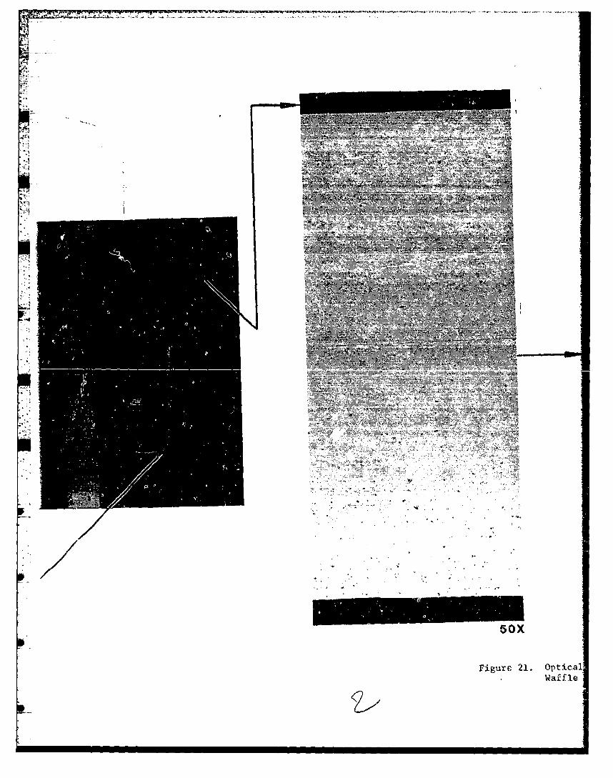
21 optical Micrograpbh,. from the Deepest Corner of the WafflePan Showing No Cavitation ..... ................. 65
22 Avionics Deck Waffle Pan After Final Trimning ......... 67
23 Avionics DAfter Assembly .................... 68
24 Avionics Deck Test Loadiing ........ ................. ... 70
25 Avionics Deck Test Setup ........ ............ .. 73
vii
EFT INTENTIONALLY BLANK
viii
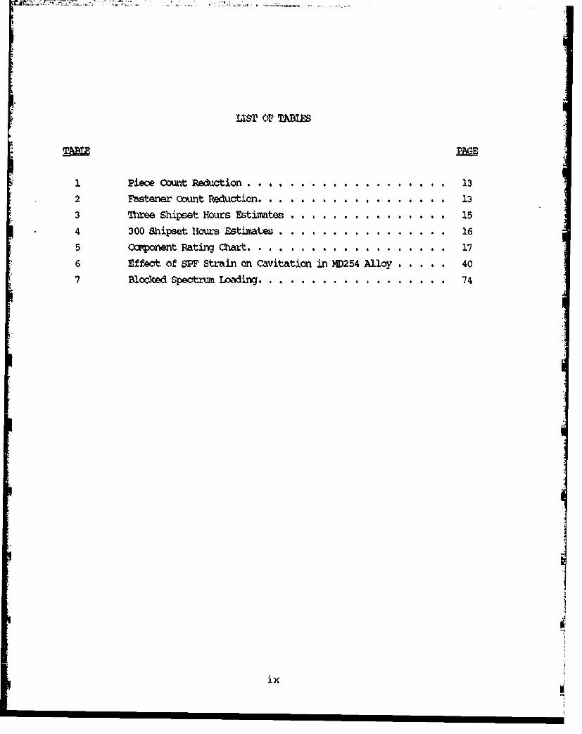
ItSM OF TABP M
1 PieOe 00t, Reduction . . . . ....... . . . . . . . 132 Fastener oount Reduction... . . ............ 13
3 nwoe Shipset Hours Estimtes ... ....... # ... 15
4 300 Shipset Hours FZtiateuIs ........ ... . 165 Caxonet Rating Chart, ... . ........ 176 Effect of SPF Strain on cavitation in MD254 Alloy . . . . . 40
7 Bloaked Spectrw LoadiMr. . . . . . . . . . . . 74
ix
SECTION 1
INTRODUCTIONr,
Superplastic forming (SPF) is one of the most important
technologies recently developed. Superplasticity is a unique
property, exhibited by certain alloys having a characteristic
microstructure, by which alloys undergo large uniform elongationswithout fracture when subjected to appropriate temperature and
forming strain rates, This unique property makes it possible to
form parts with much tighter radii and complex shapes.
The use of SPF technology in fabrication of fighter
structures offer several advantages. The main advantage is the
r aduC-.on in pece coun.. The SP, ' process m-ne . ... ny s ... t.eparts into one monolithic structure, thus reducing the number of
details, fasteners, and costs associated with materials, fabrica-
tion, assembly, tooling and in,.pection. In addition, installa-
tion, maintenance and labor hours are greatly reduced. Lighter
weight also results from a reduction in the overlapping areas ofindividual pieces.
Another major advantage of SPF is the elimination of"springback". Conventionally formed parts have significant
residual stresses and tend to form back to their original shape
upon the removal of forming pressures. SPF parts have mninimalresidual stresses and consequently less tendency for springback.
This reduced springback results in closer tolerances which could
be advantageous during the assembly of SPF parts.
a
11
1.1 BACKGROUND
The bulk of SPF development work in the past has con-centrated on superplastic forming of titaniumn. Superplastic
forming of titanium has demonstrated significant cost and weight
savings for selected structural airframe parts. A number of SPFtitanium parts are being used in production aircraft. The suc-
cessful applications of SPF titanium technology to aircraftstructures led to exploring the SPF potential of aluminum.Initial explorations of SPF in 7000-series aluminum alloys showedconsiderable promise. Air Force Contract No. F33615-79-C-3218
(Reference 1) demonstrated that high strength aluminum alloys,such as 7075 and 7475, have SPF potential after their wroughtforms have undergone grain refinement. The grain refinement is
achieved through a thermomechanical process that produces grainsize in the 9-gm to 15-pm range. This grain si.ze enables thematerial to undergo tensile elongations of about 400 percent in
the 850 to 900"F range. We feel that other alloys, includingpowder aluminum alloys, have the potential to provide valuablecost and weight savings through superplastic forming.
The feasibility to produce SPF aluminum full scalestructural airframe parts has been successfully demonstrated on
Air Force Contract No. F33615-80-C-3240 (Reference 2). The cost
and weight savings, with the quality of the parts produced,demonstrated the valuable potential of the SPF aluminum process.
1.2 OBJECTIVE
The objective of this program was to exploit and devel-
op applications of SPF aluminum and demonstrate the process as aviable means of producing structural airframe parts that are morecost effective than conventionally produced parts. Several
aluminum alloys were evaluated for their SPF potential and thebest one selected for further evaluation and final component
fabrication. The structural integrity of the part(s) was then
demonstrated by structural testing.
2

1.3 SCOPE
The scope of this program was to select, design, fabri-
cate, evaluate and test SPF alumvinum structlural airframe parts.
The SPF parts were to be designed as replacements for baseline
components on an existing vehicle. The Air Force was provided
with a full scale SPF aluminum demonstration airframe component
that was evaluated and tested for its structural integrity. The
program was divided into five tasks with the following specific
objectives.
Task I - Part Selection & Design
From the results of design/producibility trade studies
on several candidate structural components, production SPF de-
signs were developed for two components showing the most bene-
fits. Additionally, preliminary design criteria, material pro-
curement, and process specification documents were drawn up. A
subcomponent test plan for each selected component was formulat-
ed.
Task II - Material Selection and Evaluation
From the results of a preliminary evaluation of tbhee
aluminum alloys thermomechanically treated to optimize superplhi-
ticity, one alloy was chosen for extensive evaluation and fabri-
caticn of the structural components. This task was to run con-
currently with Task I.
aT•sk ITI - Producibility ForminQ Tests
Subcomponents which represented the most severe forming
areas of each component were fabricated and tested. The selected
subcomponents were to have various cross sections which simulated
critical forming areas of the full scale parts.
3

Task IV -Part Fabrication
A full scale SPF component was fabricated and assembled
in this task.
Task V -Part Evaluation and Structural verification
The full scale SPF part was examined for its forming
quality and tested for structural integrity.
4
SECTION 2
PART SELECTION AND DESIGN
This task involved the selection and design of two
candidate SPF components. The selected parts would utilize the
unique capabilities of the SPF process to provide significantcost and weight savings. The selected parts were designed as
replacements for baseline components on an existing vehicle.
The selection of the parts and their design is discussed in the
following subsections.
2.1 PARTS SELECTION
The Northrop F-5E/F aircraft was selected as the
baseline aircraft for this program. The F-SE/F fuselage is of
conventional frame and longeron construction. Secondary struc-
tures such as doors, fairings, etc., are a combination of waffle
pans or honeycomb construction. Therefore, any structural comipo-
nent selected from the F-5E/F would be an excellent generic
example of fighter aircraft structure. A number of candidate
parts representing both primary and secondary structures were
considered. Obvious areas of potential payoff were applications
where labor intensive subassemblies, extensive machining andcorresponding material wastage could be eliminated. Also, the
selected parts were to be produced from sheet material and de-
signed to meet all service life loading and if applicable, fa-
tigue loading requirements of their respective baseline compo-
nents.
2. 1.1 Conceptual Design Studies
Conceptual design studies involved a redesign of the
selected components as SPF assemblies. The major emphasis was on
5

reduction of piece count and assembly costs. Four candidate
structural assemblies were selected for preliminary evaluation,representing the most advantageous application of superplastic
forming on the F-5E/F aircraft. Structural descriptions of these
four assemblies are given below.
CONCEPT 1 - Forward Avionics Deck
As shown in Figure 1, the original assembly was con-
prised of a six-part split-level deck supported by eight frame
segments and six beam segments, with their adjacent shear webs
joined by separate shear clips. This structure Js bounded by two
machined bulkheads and left and right hand longerons which join
the deck to the outer skin providing lands for the avionics
compartment access door. The part count breakdown is as fol-
lows: 21 stretch-formed extrusions, 39 hydroformed sheet metal
details, 2 flat sheet decks, and 1 stretch-formed outer skin,
totaling 63 parts in all.
The original SP? assembly, Figure 1, was designed
around five pieces, two of which were common to the original
design. All of the substructure was combined into one wafflepan. The upper deck was a one-piece pan. The outer skin was
superplastically formed in a two-piece thermoform die. A waffle
pattern insert and outer skin shim were added to the die so the
waffle pan could be formed. Additional inserts and waffle panshims were added to the die so the inner deck pan could be
formed. Where necessary, multiple sheets were formed on both the
waffle pan and inner skin to provide required doublers. All the
necessary parts were formed in one segmented die assuring properfitup for the subsequent assemblies. The design was subsequently
modified based on the results of forming producibility tests.
The details of modification are discussed in Volume II (Reference
3).
6

• 0w
'/\\ i
'
• • .>j D
o.
I- .
I- ,,,I
L 0w
The final SPF assembly was made from only ten pieces.
All of the substructure was combined into one waffled pan (four
formers and three intercostals. The final assembly was rivet
bonded and cured in an oven.
CONCEPT 2 - Nose Gear Wheel Door
The original design is a simple honeycomb stiffened pre-
warped door supported on two hinges and articulated by an actua-
tor attached to the left hand forward corner (Figure 2). Thedesign is complicated by a cooling air outlet vent located in the
center of the door.
The SPF design (Figure 2) substituted a ribbed pan for
the honeycomb core and integrates several vent pieces into the
door skin and inner pan. This design is an all bonded assembly.
The outer skin, the ribbed stiffening pan and the
louver stiffener would be stperplastically formed. The three
doublers, the fairing, and the louver inner surface would be
formed conventionally. Also, there are two machined aluminum
backup ribs at the hinge locations to provide hinge support and
transverse stiffness.
CONCEPT 3 - Trailing Edge Flap
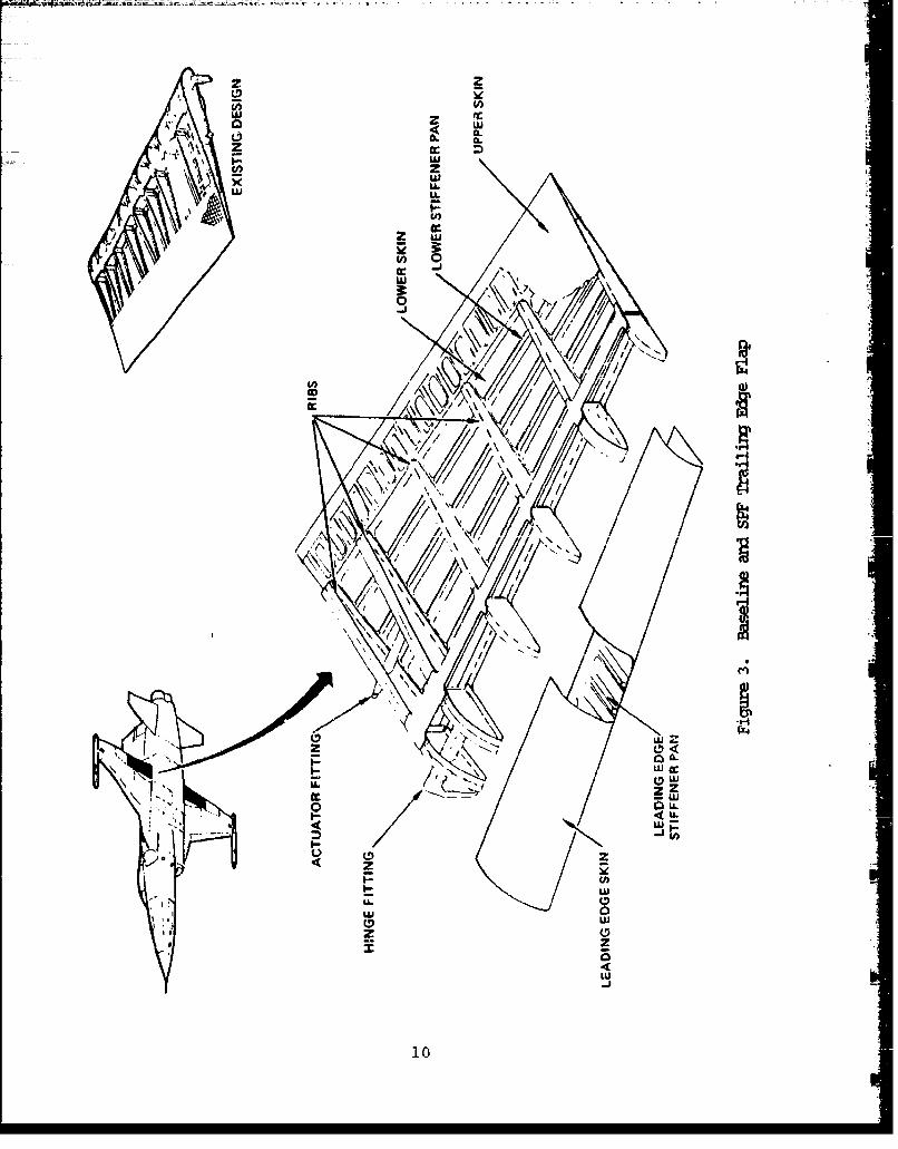
The original design (Figure 3) of the trailing edge
flap consists of ten, two-piece ribs equally spaced along a main
spar at the 77 percent chord plane. There are also leading and
trailing edge spars, the latter being a closeout member for the
separate bonded honeycomb trailing edge assembly. The two in-
board most ribs are actually double ribs, strengthened to accept
the concentrated loads introduced by the inboard hinge and actua-
tor fittings. The outboard hinge support rib is a machined
fitting.
8

I w-' z
LL
w <-ww
-- j
x <L'U
z
0/
U-)
27
w 2 ')
LULL
LLJ ,
4 V/O\( /\
\10 \ \;/
U)
\ \ /\ \CCLL, w
/ cI*Z
zz
10
The companion SPF design (Figure 3) investigates thetrade-off of skin stiffening versus rib count and apacing. Everyother rib was eliminated while spanwise beads were added asalternative skin stiffeners. At the trailing edge the stiffenerpattern turned into a waffle pattern and replacing the separatehoneycomb bonded assembly of the original design. The spanwiseskin stiffening also eliminated the need for a forward spar. Allthe remaining ribs could be superplastically formed, eliminatingthe need for shear clips. The assembly of the deck could beaccomplished by weldbonding and mechanical fastening.
CONCEPT 4 - Wing Leading Edge Extensgjj_
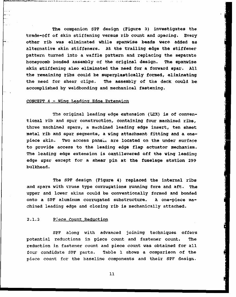
The original leading edge extension (UEX) is of conven-tional rib and spar construction, containing four machined ribs,three machined spars, a machined leading edge insert, ten sheetmetal rib and spar segments, a wing attachment fitting and a one-piece skin. Two access pane.Lt are located on the under surfaceto provide access to the leading edge flap actuator mechanism.The leading edge extension is cantilevered off the wing leadingedge spar except for a shear pin at the fuselage station 299bulkhead.
The SPF design (Figure 4) replaced the internal ribsand spars with rruss type corrugations running fore and aft. Theupper and lower skins could be conventionally formed and bondedonto a SPF aluminum corrugated substructure. A one-piece ma-chined leading edge and closing rib is mechanically attached.
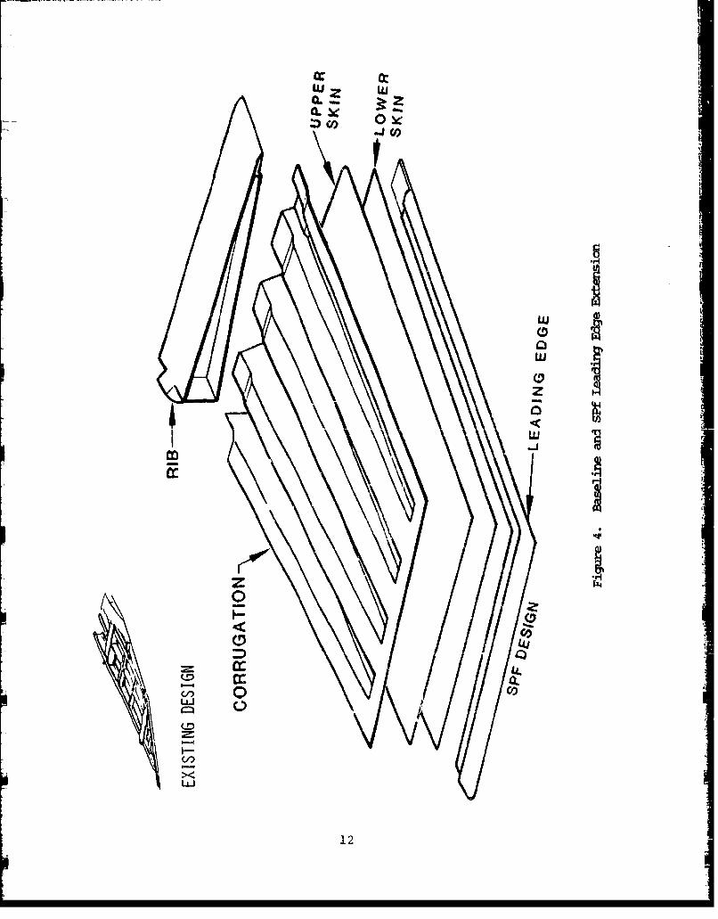
2.1.2 P.i.ece Count Reduction
SPF along with advanced joining techniques offerspotential reductions in piece count and fastener count. Thereduction in fastener count and piece count was obtained for allfour candidate SPF parts. Table 1 shows a comparison of thepiece count for the baseline components and their SPF design.
111
w z w
w
CD
z
I-L
00L4*.
12
TABLE 1. PIECE COUNT REDUCTION
I ICOMPONENT BASELINE SPF DESIGN DELTA
AVIONICS DECK 63 10 -53 -
NOSE GEAR WHEEL DOOR 21 9 -12
TRAILIYG EDGE FLAP 98 42 -56
LEADING EDGE EXTENSION 2 5 + 3
Significant reduction in piece count is seen for the avionicsdeck and trailing edge components. The number of parts for theleading edge increases by three. The original two-plece LEX wasa one-piece substructure involving extensive machining. The SPFdesign shows significant cost and weight saving potential eventhough it increased the number of details.
The fastener count comparison for the baseline and SPF
design is shown in Table 2. Significant reduction in fastener
TABLE 2. FASTENER COUNT REDUCTION
COMPONENT BASELINE SPF DESIGN DELTA
AVIONICS DECK 1009 -1009
NOSE GEAR WHEEL DOOR 27 ...- 27
TRAILING EDGE FLAP 1049 474 - 575
LEADING EDGE EXTENSION 63 I 18 - 45
13
count is seen for the avionics deck and trailing edge flap due tothe significant reduction in piece co'int and the use of weldbond-ing for the final assembly. The reduction L% f astener countresulted in a significant savings in assembly costs.
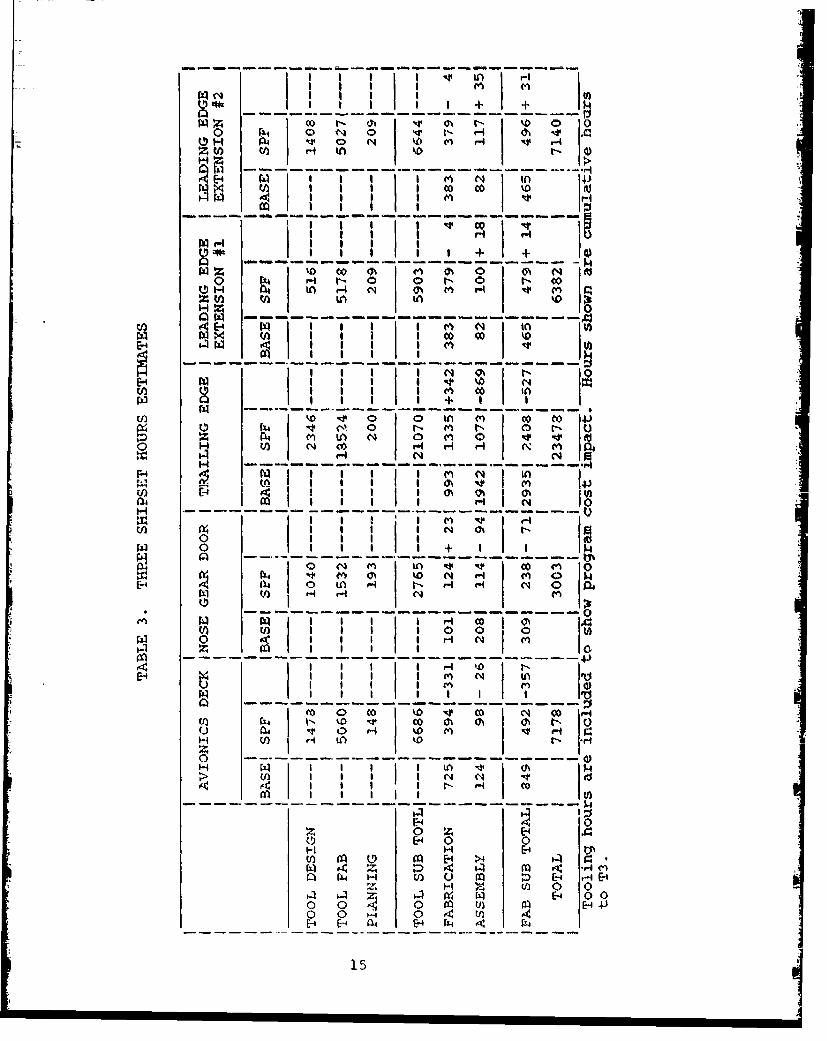
2.1.3 Manufaotur~ing Hours Estimates
Manufacturing hours estimates were obtained for allfour candidate components discussed earlier. The manufacturinghours estimates were generated on a twelve shipset/lot basis.The hours given were cumulative to the third shipset (Table 3) or300 shipsets (Table 4). The hours shown in Table 3 represent themethods and tools employed in this program and do not necessarilyreflect normal production practice. A number of hand trim anddrilling operations were assumed rather than a fully tooledproduction approach. No such deviations, however, were made withregard to the SPF forming dies. These tools were estimated asfull production tooling. The tool design fabrication and plan-ning hours estimates reflect program, not production, prac'icesand are presented as a quide to program costs for full scale
pxoduction.
For the purpose of this study, all baseline componentmanufacturing hours were estimated as if the F-5F were just goinginto production (TI) and not at the current production status(TlOOO+).
2.1..4 Component Rankin!!
The four cor.onents were re" ed, considering five mainfactors: recurring cost savings, weight savings potenrial,technology advancement, SPF risk and assembly risk. The compo-nent rating is shown in Table 5, based on a scale of 1 to 10 withI being the best. .i e recurring cost savingjs and program costranking reflect the manufacturing houis ..stimates previouslygiven.
14
I.nT
fA C4
I I I II
1±10 0 %
H -- -- -- t
H 0 00 0 + 0
oH
PA H I
I I IA LO
SE4I I I I tI I. tOI
n° I I I CO C-~I I I I c' ,I ,0 H, o
H
(0i 00 to ko -,PA 0 00 N 0
Ho -r H
I~~- I c C.4 0
U) r4
0 1
4-4
C) U) P4H
$h 1 0 (0 0. 41C N C
0 co0 ----
02 I u')
-- 11
E4 04
00 0 -wE14 0 0
(.1 02 02 (- )>H U 0 0
o 0 E-4 01 E-4 4402(-
15

U) C14 ellI +1
- 0-
N C\)tn co
cll >H
co H 'm
m LO ci
8r N+ I in "I
%D
m I
14, 0%
(o0 N AH H
16
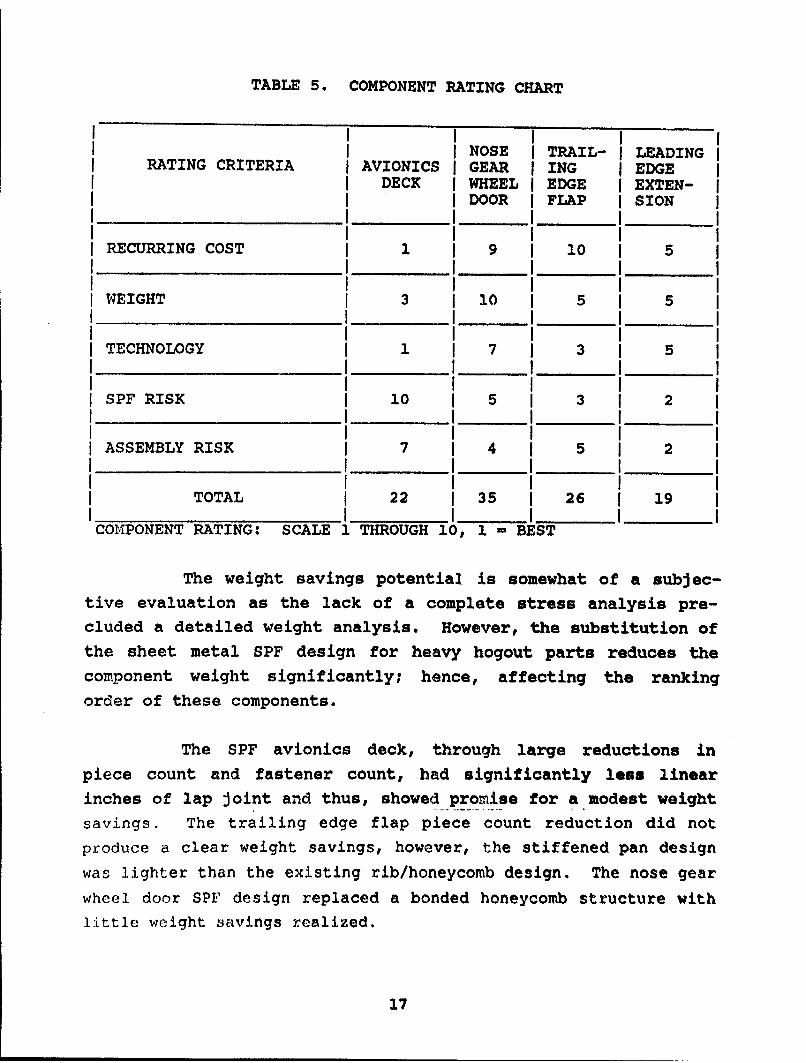
TABLE 5. COMPONENT RATING CHART
NOSE TRAIL- LEADINGRATING CRITERIA AVIONICS GEAR ING EDGE
DECK WHEEL EDGE EXTEN-DOOR FLAP SION
RECURRING COST 1 9 I10 5
WEIGHT 3 10 5 5
TECHNOLOGY 1 7 3 5
SPF RISK i10 5 3 2
ASSEMBLY RISK 7 4 5 2
TOTAL 22 I 35 26 19
COMPONENT RATING: SCALE 1 THROUGH 10, 1 = BEST
The weight savings potential is somewhat of a subjec-tive evaluation as the lack of a complete stress analysis pre-cluded a detailed weight analysis. However, the substitution ofthe sheet metal SPF design for heavy hogout parts reduces thecomponent weight significantly; hence, affecting the rankingorder of these components.
The SPF avionics deck, through large reductions inpiece count and fastener count, had significantly less linearinches of lap joint and thus, showed promise for a modest weightsavings. The trailing edge flap piece count reduction did notproduce a clear weight savings, however, the stiffened pan designwas lighter than the existing rib/honeycomb design. The nose gearwheel door SPF design replaced a bonded honeycomb structure withlittle weight savings realized.
17
The risk and technology assessments were all highly
subjective and require some explanation. The avionics deck
contains areas with over 300 percent elongation, and nests chan-
nels between closely held fuselage outer mold line and the deck
reference planes. Because its design requires the most accuracy
and greatest superplastic deformation, it therefore ranks high-est in technology advancement and highest in risk.
The nose gear wheel door offers considerably less risk
because of more modest forming requirements. It is similar in
design to many honeycomb replacement schemes used in SPF titaniumand advanced composites, therefore, rating lower on the tech-
nology advancement scale.
The LEX represents the least risk because of modest SPF
elongations (150 percent maximum) and an uncomplicated assembly.
However, the skins require the development of dies capable of
accepting preforms, and thus provide significant technology
advancement.
The trailing edge flap required the same preform ap-
proach coupled with more severe deformations, and thus showed
greater technology advancement. However, simpler assembly proce-
dures and a more accommodating design reduce the program risks.
2.1.5 Recommendations
The rating chart (Table 5) shows the LEX design as
ranking highest followed by the avionics deck with the trailing
edge flap and the nose gear door a distant third and fourth,
respectively. The relatively poor showing of the trailing edge
flap is the result of its size, which is significantly larger
than any other component, plus the large amount of parts and
fasteners; 42 and 474, respectively. The size and final piece
count contributes greatly to the program tooling costs making it
the most expensive component to fabricate. The reason for the
18

poor showing at the 300th shipset is caused by the long forming
tlmes of the many SPF details. Comparing the program quantity
estimates with the 300 shipset estimates, showing an original
hours saving, turns into a loss at 300 shipsets because of inher-
ently flatter learning curves of SPF forming (fixed run times)
and bonding.
Taking into account all the foregoing factors and
rankings, it was decided that the best component candidates for
full scale development were the avionics compartment lower deck
assembly and the wing LEX. The avionics deck was selected as
being the most cost effective and offered the most technology
advancement. The LEX was recommended for its weight savings
potential and least risk.
2.2 COMPONENTS DESIGN AND ANALYSIS
The details of design and analysis of the two selected
parts are given in Reference 3. A brief discussion is given in
the following paragraphs.
2.2.1 Avionics Deck
The original deck assembly is of conventional frame,
intercostgl and longeron construction. The frames and intercost-
als are of two-piece construction. This is to assure proper fit
between the deck and skin. Shear clips are required at each
frame and intercostal intersection to take up assembly toler-
ances.
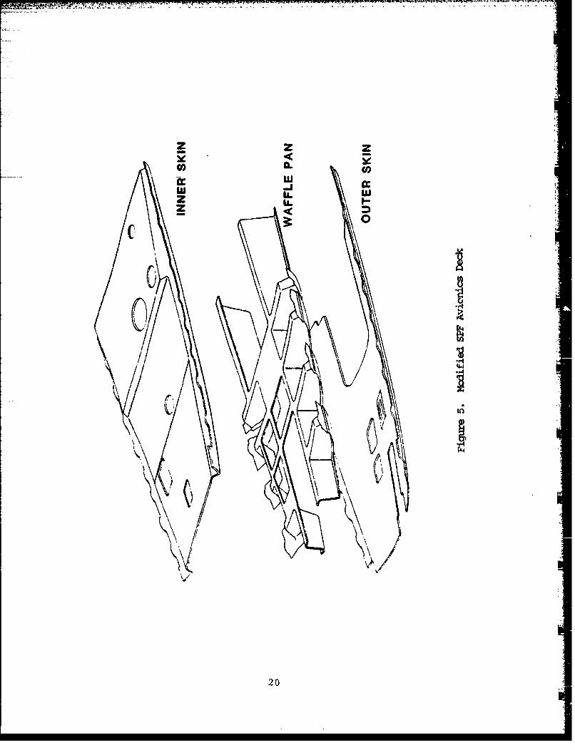
In contrast, the modified SPF design shown in Figure 5
utilizes a one-piece waffle pan to replace several frames and
intercostals. The deck is one-piece with the outboard edges
flanged to provide the mounting flange for the avionics compart-
ment access docr and the necessary cross sectional area to func-
tion as the longerons in the original design.
19
2 < re
z L2 ii.Z
.Ifc6 :>Vt/14
200

Full advantage is taken of the SPF process finer toler-
ances as all the substructural elements are devoid of separate
moldline flanges and shear clips. The rivet bonding and adhesive
bonding techniques used to assemble these components are only
possible with SPF forming tolerances.
The configuration consists of three SPF parts (outerskin, inner skin and waffle pan), three machined parts, and four
conventionally formed parts.
The avionics deck was analyzed using a NASTRAN finite jelement model. This model was created for the SPF avionics deck
structure; the rest of the F-SF nose, between the bulkhead at
fuselage station (F.S.) 47.50 and the bulkhead at F.S. 87.50, was
modeled using the actual baseline structure to provide accurateresults from loading conditions applied. This finite element
analysis was necessary, because the unconventional structure in
the SPF pan did not lend itself readily to conventional analysis
due to the discontinuous load path in the pans. A rigorous model
was necessary because; (1) the thickness gradients due to the
forming process and the discontinuous load paths were not easily
evaluated by conventional analysis, and (2) to ensure successful
redistribution of the loads as compared to the baseline.
A total of nine loading conditions were evaluated:
(1) two supersonic inflight conditions
(2) two subsonic maneuver conditions (yaw and roll)
(3) three taxing conditions
(4) two miscellaneous pressurization conditions
21
The most critical loading condition was the supersonic symmetri-cal pull up at Mach 1.30, including internal pressure and iner-tial loading performed at 7.33 g's at an intermediate weight.The rigorous model and the many loading conditions were used torepresent the actual structure as accurately as possible.
The results obtained from the model included internalloading, deflections and stresses. The peak stresses ranged from4500 to 12000 psi at the critical areas located 1/3 the distancefrom the cantilevered edge. The critical areas were checked forbuckling and crippling of the pan. In all instances, we achievedhigh margins of safety. A thinning analysis was performed on thecritical area of the pan. Tne results of this analysis showed
the most critical web located at the same area could be thinnedto 0.037 inch.
Overall, the model proved the validity of the designconcept. We concluded from these reqults that the limitingfactor of the design concept would be the forming parametersrather than the stress levels.
2.2.2 Leading Edge Extension (LEX)
The SPF design of LEX is shown in Figure 4. It con-sists of upper and lower skins with SPF corrugations. The one-piece leading edge with closing rib and attached rib are machinedparts. The corrugations are rivet bonded to the skin and leading
edge, and the rib riveted to the resulting bonded assembly.
The LEX was also analyzed using a NASTRAN finite ele-ment analysis. It was modeled using CQUAD4 and CTRIA3, exceptfor a few solid elements to represent the leading edge arrowheadfitting and the attach rib. Material thicknesses were evaluatedand included on the model. The upper and lower skin thicknesseswere a constant 0.065 inch and the rib web and flange thicknesses
22

were 0.080 inch throughout. Corrugation thicknesses were ac-
quired through a computer SPF thinning analysis. This program
calculated the thicknesses of a SPF structure at various loca-
tions given the sheet gage and properties and the dimensions ofthe corrugations.
The loading on the LEX consist primarily of flight
pressure loads. This pressure loading is a trapezoidal distribu-tion running spanwise along the upper skin. The loads ranged
from 9.97 to 18.02 psi, inboard to outboard, respectively.
The stress results from the flight pressure load
case were less than 16 ksi allowing the upper and lower skin to
be thinned down from 0.065 to 0.050 inch.
The results of the revised NASTRAN run yielded the
maximum major principal stress of 35,565 psi located on the
forward, inboard upper skin of the LEX. This stress is a local-
ized stress which occurs in the area of the lug, a location which
* takes a majority of the loading. The minimum major principal
stress was -4760 psi, which was located on the lower skin of theLEX in the same area as the maximum stress. Overall, the stress-
es on the upper skin of the LEX are low (<10 ksi).
2
23
LEFT INTENTIONALLY BLANK
24

SECTION 3
MAT SELECTION AND EVALUATION
This task was designed to do the preliminary screening
of existing aluminum alloys and to select candidate alloys withSPF potential for further evaluation. The alloy having the bestcombination of SPF potential and post-SPF mechanical properties
was selected for detailed evaluation and fabrication of airframe
structures. The details of material selection and evaluation
are given in Reference 3. The key steps in the selection process
and the post-SPF properties of the selected alloy are briefly
discussed here.
Subsequent to material selection, a new SPF aluminum
material 'MD254' was developed by the Reynolds Metals Company.This material had better superplastic properties than the origi-nally selected material (7475) and was therefore used for parts
fabrication.
3.1 MATERIAL SCREENING
A preliminary screening of aluminum alloys was done to
select three materials which were to be further evaluated for
their SPF potential. These alloys were to be procured in a fine
grained condition or given a thermomechanical treatment to refine
their grain size.
The candidate materials included both ingot and powder
metallurgy aluminum alloys and offered a broad range of service
properties including strength, damage tolerance and durability.
The ingot alloys; 7475, 7075, 7050, 2024, Supral 100, Alcan 08050
25
and powder alloy, X7091 were considered. The three alloys se-
lected for preliminary evaluation and a brief rationale for their
selection are as follows.
(1) 74?5-AlIOy. It is a high strength aluminum alloy
with a relatively clean microstructure (fewer iron
and silicon bearing inclusions than 7075, i.e.,
fewer natural sites for cavitation during the SPFdeformation). It has strength and stress corro-
sion cracking resistance comparable to 7075-T6,
and fracture toughness and exfoliation resistance(in 7475-T61 condition) superior to 7075-T6. Itcould be mill-produced in fine grained condition,
has demonstrated capabilities for large super-
plastic deformation, and can be procured fromseveral sources in the U.S.
(2) 7050OAlloy. It offers high strength and various
other service properties characteristic of the7XXX alloys. In addition, it has a lower sensi-tivity to the rate of quenching than other alloys
in the same family. This property was considereddesirable as optimum strength could be developed
in an as formed 7050 SPF component by a slower
cool than water quench, e.g., by air cooling. Asa result, problems associat.ed with warpage due to
thermal stresses induced during quenching would besignificantly reduced. Also, the presence of
zirconium in the 7050 alloy also affords it moreefficiency in grain refinement during mill proc-
essing. This alloy could also be easily procured
from several domestic sources.
(3) X7091 Alloy. This alloy was selected because of
its high strength, high corrosion resistance, and
26

excellent toughness (without compromising
strength). its superior properties are due to an
inherently clean, fine grained and uniform struo-
ture in this alloy. The combination of the desir-
able service properties, typical of the 7XXX
alloys, and the fine microstruoture inherent in
the P/M alloys like X7091, results in a structural
aluminum alloy with a high SPF potential. This
alloy can also be obtained from several sources.
3.2 MATERIAL SELECTION
The material selection was primarily based on the
superplastic response, process parameters, mav nm useful elonga-
tion, and post-SPF properties. The results of the preliminary
evaluations were analyzed and a final alloy was selected that
best fit the design requirements of the candidate components.
1ill stock of three selected alloys, plates of 7475 and 7050, and
extruded bars of X7091, were thermomechanically processed, heat-
treated and rolled, into sheets with nominal gauge thicknesses of
0.060, 0.090, and 0.125 inch using the most desirable of the
treatments developed under a joint Northrop - Reynolds IR&D
program. A microstructural analysis and cone tests were conduct-
ed on the thermomechanicully treated material.
The following paragraphs discuss microstructure and
superplasticity capability evaluations which led to the choice of
7475 as the most suitable of the three alloys for use in this
program.
3.2.1 MicrostructuralEvaluat~ioq
A three-dimensi,)nal microstructure evaluation was
carried out for all three alloys. The details of these evalua-
tigns are described in Reference 3.
27
The 7475 sheet material exhibited the rinest grainstructure of the three alloys examined. The average diameter was
between e.3 and 9.1 micrometers, measured transverse to thesheet rolling direction. The standard deviations fov thesemeasurements were also the lowest. The average diameters In the
direction parallel to the sheet rolling direction ranged between
13.0 and 16.3 micrometers.
The grain structure of the 7050 material was slightlycoarser than that of 7475. The average diameter at the centerline was between 10.2 and 11.9 micrometers, measured transverseto the sheet rolling direction. The grain structure in the
center of the sheet was similar to that on the surface.
The microstructure of the X7091 material varied widelydepending upon where the measurements were made. The grain
structure .1n the center of the sheet was generally ftrier thanaway from it. The grains near the sample surface were very
coarse with aove of the average diametars exceeding, 50 mcrome-ters. These large grains were observed in all of the X7091
sheets produced by the various processing treatments.
3.2.2 !_qe Test. s
The classical approach of uniaxial tension testing for
mnaterial plasticity evaluation was not used in the present inves-tigation. Instead, the evaluation was done by biaxial tension
forming of a cone shaped specimen. The main reason for this wasto ensure that the test methods employed measured true material
superplasticity in the aluminum alloys without being affected byother phei.omena occurring which may influence their superplastic
ductility. Aluminum alloys fail during the SPF process by amechanism involving cavity nucleation at grain boundaries andcavity growth with increasing SPF strain rather than by the
classical mechanism of necking from strain localization, as inTi-6AI-4V and other titanium alloys. An elevated temperature
28
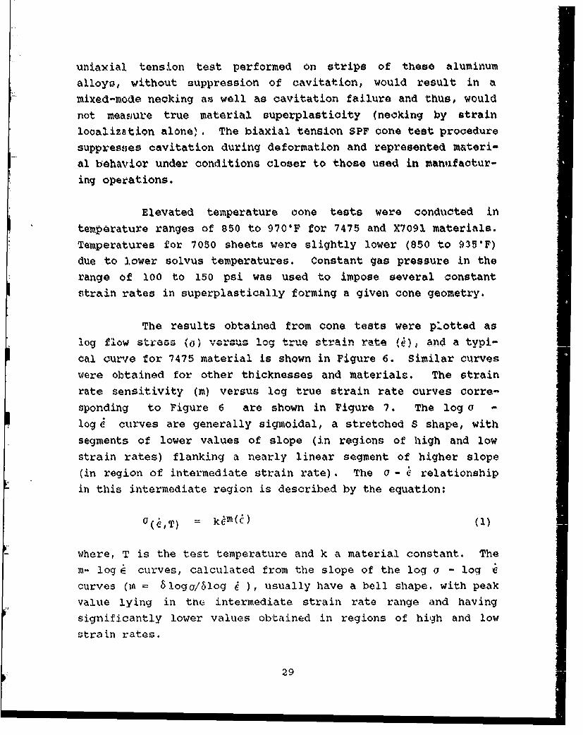
uniaxial tension test performed on strips of these aluminumalloys, without suppression of cavitation, would result in amixed-mode necking as well as cavitation failure and thus, wouldnot measure true material superplastioity (necking by strainlooalization alone). The biaxial tension SPF cone test proceduresuppress;es cavitation during deformation and represented m&teri-al behavior under conditions closer to those used in manufactur-ing operations.
Elevated temperature cone tests were conducted intemperature ranges of 850 to 970'F for 7475 and X7091 materials.Temperatures for 7050 sheets were slightly lower (850 to 9351F)due to lower solvus temperatures. Constant gas pressure in therange of 100 to 150 psi was used to impose several constantstrain rates in superplastically forming a given cone geometry.
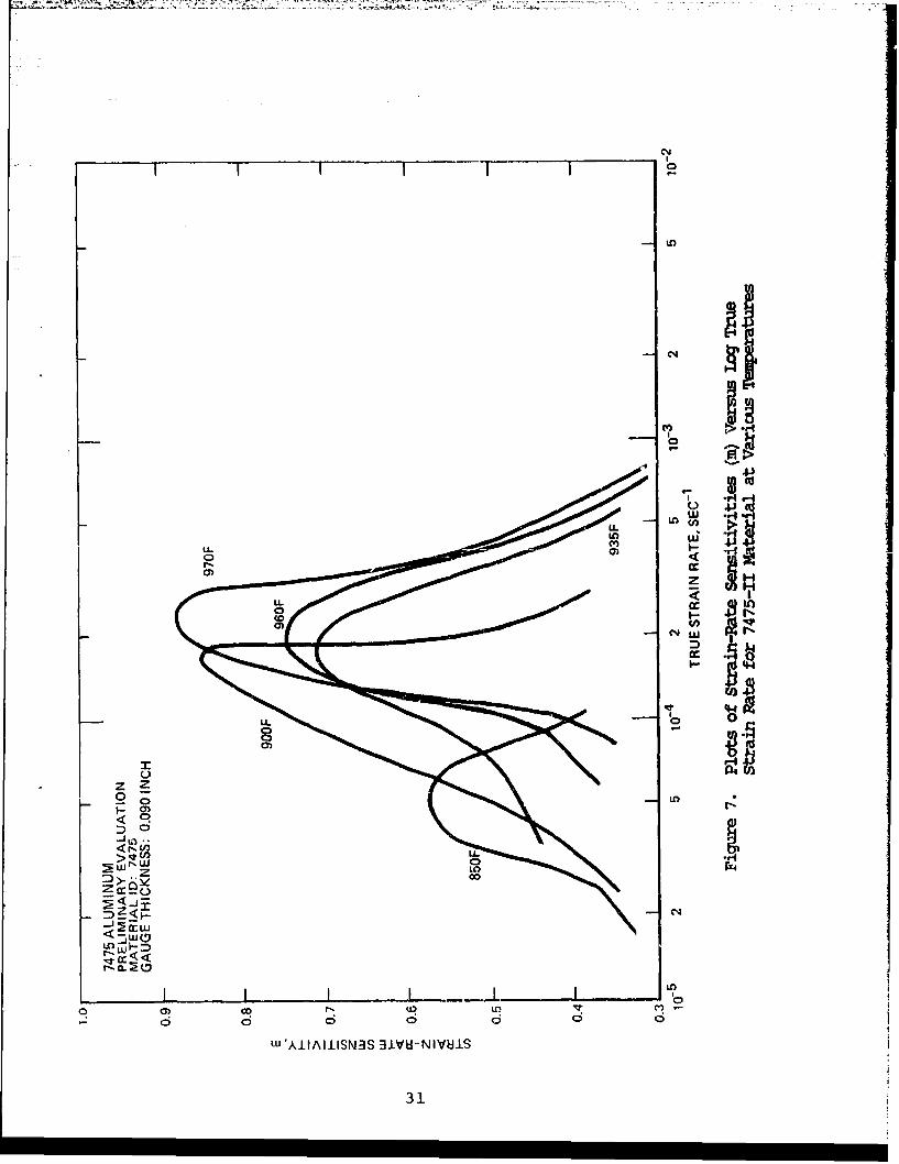
The results obtained from cone tests were plotted aslog flow stress (o) varsus log true strain rate (1); and a typi-cal curve for 7475 material is shown in Figure 6. Similar curveswere obtained for other thicknesses and materials. The strainrate sensitivity (m) versus log true strain rate curves corre-
sponding to Figure 6 are shown in Figure 7. The log o -log s curves are generally sigmoidal, a stretched S shape, withsegments of lower values of slope (in regions of high and low
strain rates) flanking a nearly linear segment of higher slope(in region of intermediate strain rate). The a - ý relationship
in this intermediate region is described by the equation:
G(ý,T) = ktm(Q)(i
where, T is the test temperature and k a material constant. Them- log E curves, calculated from the slope of the log a - log c
curves (ia = Sloga/61og 4 ), usually have a bell shape., with peakvalue lying in tn• intermediate strain rate range and havingsignificantly lower values obtained in regions of high and lowstrain rates.
29

Lu -) W U
LA.
0CCr
C3 L.
OH
N V4r*cu30H
CNJ
I V ~ I IN
Inn
coJ
C-)-
Z Z0 0 - )
CD
Sw LorZz c
a! Iý Iq I L
LU 'AkltAi±SN3S 3LVHI--NIVUI.S
31
A brief review of these results indicated that the 7475
alloy generally had the highest peak m values. The range of peakma values for the various sheet gauges evaluated over the tempera-
tures of 900 to 9706F was 0.64 to 0.89. The corresponding peak m
values were in the range of 0.59 to 0.89 (between the tempera-
tures of 900 to 9350F) for the 7050 alloy and 0.3 to 0.5 (at
970°F) for the X7091 alloy. Higher peak m values are known to be
related to superplastic elongation to fracture in a variety ofmaterials (Reference 4). The higher the peak m value of analloy, the higher is its projected superplastic elongation. The
strain rates corresponding to the peak m were also in a higherstrain rate range for 7475 than for the other alloys: 1.5 x 10⁻⁴
to 5 x 10⁻⁴ sec-I for 7050 and 3 x 10⁻⁴ to 4 x 10⁻⁴ sec-I for
X7091. The differences in the strain rates are important, since
higher strain rates would result in shorter fabrication time and,
therefore, lower cost for a given component. Finally, the flow
stresses corresponding to the peak m values were the lowest for
7475 of the three alloys evaluated: approximately 350 psi at 1.5X 10⁻⁴ sec- 1 and 1,000 psi at 10-3 sec-I for 7475, compared to400 to 500 psi at 7 x 10⁻⁵ sec- 1 and 1,000 to 1,200 psi at 5 x10⁻⁴ sec-I for 7050, and 550 to 800 psi at 3 x 10⁻⁴ sec- 1 and 650to 900 psi at 4 x 10⁻⁴ sec-I for X7091. Lower flow stresses are
advantageous, since they translate into lower gas pressure re-
quirements during forming and, due to the lower resultant stressconcentrations, resulted in reduced cavitation.
3 .3 MATERIAL EVALUATION
The 7475 alloy selected for the program was thoroughlyevaluated for its SPF potential, post-SPF properties, microstruc-
ture, and secondary processability of the formed material. The
properties of mill-produced and laboratory produced 7475 (0.090-
inch and 0.125-inch thicknesses) were compared and comprehensivepost-SPF mechanical property data, both static and fatigue, were
obtained. Static properties were generated f-3r longitudinal and
transverse orientations, two initial. sheet thicknesses, and three
32
SPF strains (50, 100 and 150 percent). Selected combinations of
these variations were used for fatigue and environmental tests.
We also investigated stress corrosion, exfoliation and fatigue
crack growth in salt water.
Secondary processing factors examined included the
ability of SPF material to accept paint, adhesives and anodic
coatings. Spot and seam weld qualities and chemical milling were* also evaluated.
The following observations were made from the above
evaluation (Reference 3):
3.3.1 Cavitation Behavior of 7475 Alloy
Virtually no cavitation (<0.5 areal percent) was ob-
served up to 60 percent SPF strain at three forming temperatures
(850, 935 and 970"F). Beyond this strain, cavitation began to
increase with increasing strain. Up to 100 percent strain was
achieved with a cavitation level of 1 percent at 935"F tempera-
ture; this value of strain (with 1 percent cavitation) increasedto 150 percent when the temperature was raised to 970"F. Beyond
100 percent strain at 935"F and 150 percent strain at 970cF,
cavitation increased dramatically with increasing strain. Values
of areal cavitation in excess of 12 percent were obtained with
strains of 320 percent. As expected, the effect of higher tem-
peratures was to suppress cavitation. The effect of temperature
was to delay cavitation (due to a more efficient accommodation of
cavities by the faster diffusion at the higher temperatures
rather than to retard its rate. Thus, a higher temperature
served to delay the onset of cavitation but did not significantly
influence the rate of growth of cavities. Strain rate showed asimilar effect on cavitation as temperature.
33
3.3.2 Mill-produced Versus LaborAtogy Material
SPP potential of 7475 mill-produced material (0.09- and0.125-inch thicknesses) was comparable to that of laboratoryproduced material. The mechanical properties of mill-produced7475 material in T6 condition were comparable to those of 7075-T6
aluminum sheet.
3.3.3 Tensile Tests
Tensile tests were conducted on SPF sheet coupons inaccordance with ASTM E-8. Results obtained from post-SPF sheetthickness of 0.090 and 0.125 inch (with SPF thickness strains of50, 100 and 150 percent) indicated that the ultimate and yieldstrengths as well as elongation were generally independent of theamount of prior SPF strain. The yield and ultimate strengthswere above the NIL-Handbook 5 required values and the elongationwas equal to or slightly below the MIL-Handbook 5 requirements.The rolling direction did not noticeably influence the post-SPF
tensile properties.
3.3.4 Compression Tests
These tests were conducted in accordance with ASTM E-9.The compression strength for up to 150 percent SPF strain were
appreciably higher than the MIL-Handbook 5 requirement.
3.3.5 Bearing Tests
Bearing specimens were tested in accordance with ASTM
E238 for initial thicknesses of 0.090 and 0.125 inch. For the0.125-inch thick sheet after a SPF strain of 150 percent,strengths were comparable to MIL-Handbook 5 values. However, forthe 0.090-inch thick sheet, both ultimate and yield strengths metthe MIL-Handbook 5 requirement within the SPF strain range of 50
to 150 percent.
341
3.3.6 Shear-Punch Tests
We found that the shear-punch strength values for
0.125-inch thickness were higher than MIL-Handbook 5 require-ments. However, the 0.090-inch thick material had higher valuesthan MIL-Handbook 5 requirements at SPF strains of 50 and 100
percent and slightly lower values for 150 percent strain.
3.3.7 Stress-Corrosion Tests
j The stress-corrosion test was conducted on the post-SPF* 7475-T6 specimens in accordance with ASTM G44. A stress equiva-* lent to 74 percent of the yield strength of the 7475-T6 was
exerted on each specimen which was alternately immersed in a 3.5
percent salt water at room temperature. Only specimens having an
initial sheet thickness of 0.125 inch and superplastically de-formed to 50 and 150 percent strains were tested. The average
failure time was about 60 days, regardless of the magnitude ofSPF strain, as compared to the required minimum failure time of
30 days.
3.3.8 Exfoliation Corrosion Tests
Exfoliation resistance of specimens formed at the three
SPF strains was found to be comparable to conventional 7475-T6material.
3.3.9 Faticrue Crack Growth Tests in Air
Fatigue crack growth in longitudinal transverse (L-T)and T-L directions in specimens, formed at 50 and 150 percent SPFstrain, were found to be comparable to conventional 7475-T6
sheets.
35
3.3.10 Anodizina Tests
The post-SPF material in the T6 temper was observed tobe identical to 7075-T6 in its response to the anodizing treat-ment.
3.3.11 Painting Tests
Using the standard procedures, no difference was ob-served in the paint adhesion characteristics of the post-SPF 7475material and the conventional 7075 sheet. The post-SPF materialalso successfully met the impact and wet tape strength require-ments in accordance with the Northrop specifications NAI 1269/NAI1278.
3.3.12 Chem Milling Tests
Chem milling tests were conducted using Northrop'sproduction facilities. The following results were obtained withregard to the rate of chem milling and the subsequent fatiguetests.
3.3.12.1 Chem Milling Rate
Thickness measurements were taken after submergingsamples in the milling solution for one minute; this process wasrepeated five times and a cumulative metal removal in five min-utes was calculated. The average chem milling rate in the post-SPF 7475 (T6 temper) was approximately 0.006 in/min, which ishigher than 0.002 to 0.004 in/min for the conventional 7075-T6sheet.
3.3.12.2 Fatigge Tests
Smooth fatigue tests were conducted by applying maximumstresses in the range of 30 to 50 ksi at a stress ratio (R) of
36

0.1. we observed that the fatigue life of the post-SPF 7475
after chem milling was slightly lower than that of the conven-
tional 7475-T61 sheets. We believe that this difference may be
related to some surface effects in the post-SPF material, since
most of the specimens failed in areas other than the narrowest,
and no cavitation was observed near the fracture region in the
specimens examined. In the specimens tested in the present
studies, the prior rolling direction (L or T) or the total SPF
strain (50 or 150 percent) appeared to make no difference in the
fLtigue performance of the material.
3.3.13 Adhesive Bonding Tests
The following tests were conducted to determ-.ie the
adhesive bondability and the resultant bond strength of the post-
SPF material.
3.3.14 Lan Shear Tests
Post-SPF 7475 sheets were anodized in phosphoric acid,
sprayed with BR127 primer, and bonded with FM73 film adhesive per
Northrop Specification MA108. The average lap shear strength of
six tests was 5400 lbs compared to the minimum strength of 4200
lbs required by the Northrop specification NAI 1286.
3.3.15 Climbing Drum Peel Tests
Even the lowest value of strength obtained (108 lbs/in)
is higher than that for conventional high strength aluminum alloy
sheets. However, the samples with low SPF strains had a higher
strength (144 and 153 lbs/in) than those with high SPF strains
(108 lbs/in).
37
3.3.16 Resistance geam Welding Tests
Consistently defect free, reproducible resistance seam
welds were obtained in the post-SPF 7475 (T6 temper) sheet speci-
mens using the normal welding parameters for 7075-T6 sheets of
equivalent thickness. X-ray radiography indicated no internal
defects in the weld zone. Peel tests resulted in material fail-
ing outside the fusion zone, indicating the high strength of the
seam welds.
3.3.17 Weldbonding Tests
We determined that the welding parameters established
for 7075-T6 sheets can be reliably used to weld the post-SPF 7475
(T6) sheets of comparable thickness. Uncured joint strength
values of 600 to 850 lbs were obtained, depending upon the weld-
ing current used. These values are the same as those normally
obtained for the conventional 7075-T6 sheets. Surface treatment
was based on the Northrop process specification.
3.4 MATERIAL SUBSTITUTION TO MD254
Following Northrop's IR&D evaluation of various new
high strength SPF aluminum alloy sheets, a recommendation was
made to the Air Force Program Monitor to substitute the selected
material, 7475, with Reynolds Metals Company's new production
7475 alloy material, MD254, a highly superplastic alloy. In Nor-
throp's evaluation, this material had been superplastically de-
formed to over 1,000 percent strain without appreciable (<0.5
percent area) cavitation. Following Air Force approval of this
substitution, full size production sheets of MD254 were procured
in 0.090- and 0.160-inch gauges and further evaluation was car-
ried out.
38

The as received grain structure of the 0.090-inch thick
material had the average longitudinal and transverse grain sizes
of 17.0 and 8.5 m, respectively. Thus, the grains had an aspect
ratio of 2.0. The 0.160-inch thick material had the average
longitudinal and transverse grain sizes of 17.5 and 8.4 m,
respectively.
Room temperature tensile tests were conducted on the
material in T6 temper. The 0.090 inch MD254-T6 sheet properties
compared quite favorably with the 0.090 inch 7075-T6 properties.The 0.0160 inch MD254-T6 strength properties were somewhat lower.
The ductility of MD254 sheets in both thicknesses was considera-
bly higher than that of 0.090 inch 7075-T6. In biaxial-tension
cone tests at 970°F, the 0.090 inch thick sheets developed high
thickness strains prior to rupture. In each case the dual pres-
surization approach was utilized for suppression of cavitation
during SPF with strains over 1,000 percent. A significant frac-
tion of these strains were found to be almost without cavitation.
In one test, 1430 percent strain was obtained prior to rupture
(at a strain rate of 1.3 x 10⁻⁴ sec-1 ), virtually all of the
strain was without cavitation (<0.5 percent). These results areshown in Table 6.
The 0.160 inch thick sheets also developed similarly
high strains prior to rupture and much of the total strain was
without cavitation. In the test specimen examined for cavita-
tion, the strain obtained at rupture was 1925 percent. At a
section representing 770 percent strain, cavitation was 0.01percent and at 1520 percent strain the cavitation was 0.6
percent. The strain corresponding to 0.2 percent cavitation
(<0.5 percent onset of cavitation) was estimated to be approxi-
mately 1,000 percent. The influence of SPF strain on cavitationis also shown in Table 6.
39
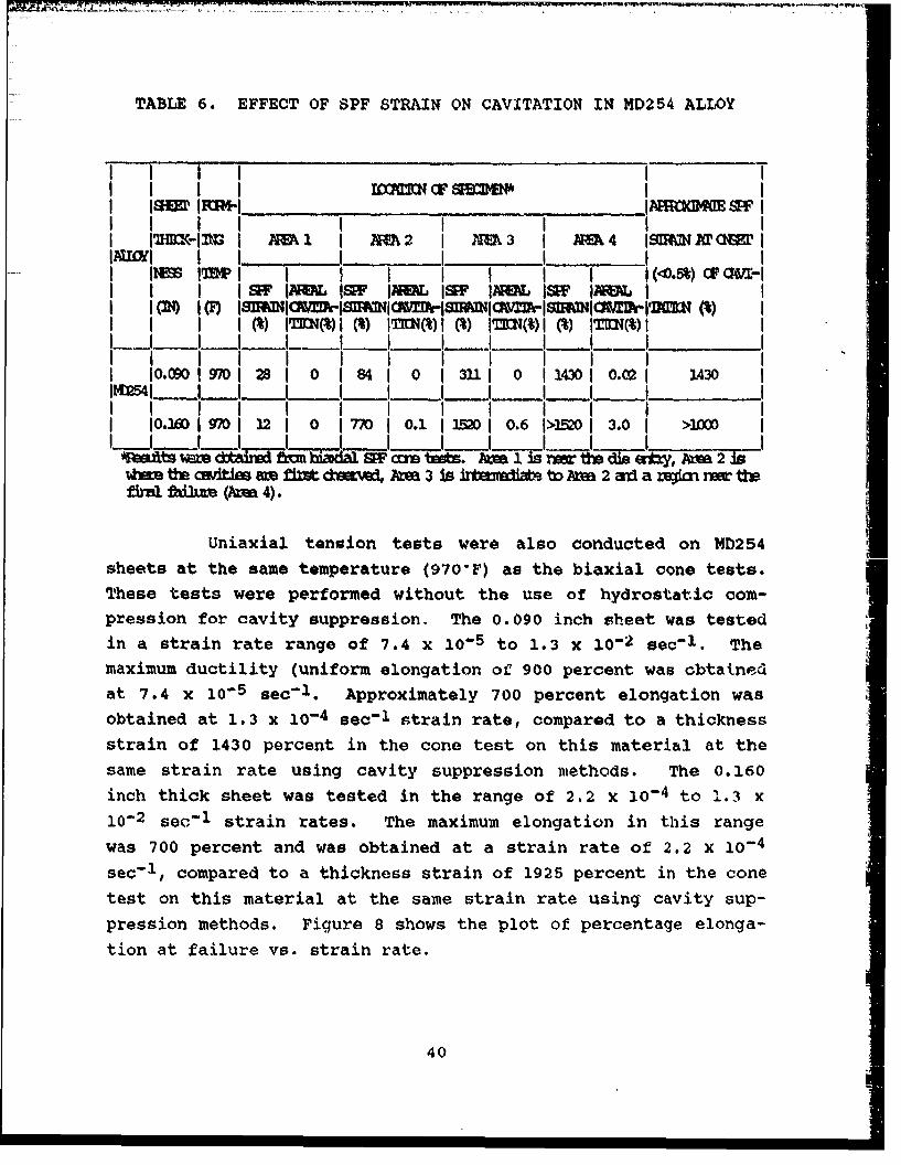
TABLE 6. EFFECT OF SPF STRAIN ON CAVITATION IN MD254 ALLOY
I IS I I I
I I I I I I I II l• i• I ___AI I 22 M 3 A 4 M MII IA I I I I I I
I IMM InW I I I Ih I I ~ I I 10%l in j =-II I I_ _ __ M JE I JS J I II im i I i I I I I iI I I I M IMMI M IM I IAM iM F i I I
I i I o I I 9 7I o.6 I>Mi 1.0 i >MIr~t Ia Itb Ir biap IN Am 1 is is th diIty va2
e th c ima n d 4 ta 3 is II•1t t AM 2 ard a recfii rer thftlfiu (AM 4).
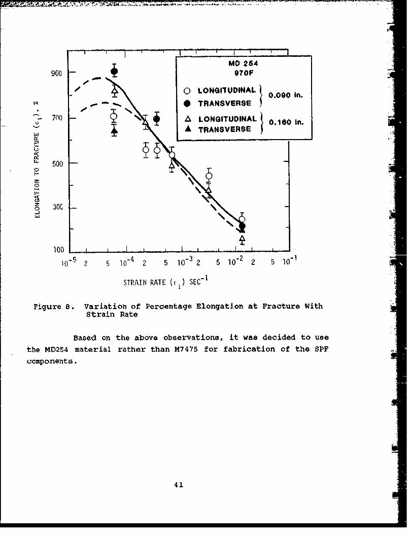
Uniaxial tension tests were also conducted on MD254sheets at the same temperature (970'F) as the biaxial cone tests.These tests were performed without the use of hydrostatic com-pression for cavity suppression. The 0.090 inch sheet was testedin a strain rate range of 7.4 X 10⁻⁵ to 1.3 x 10⁻² seo"1 . Themaximum ductility (uniform elongation of 900 percent was obtainedat 7.4 x 10⁻⁵ sec-1 . Approximately 700 percent elongation wasobtained at 1.3 x 10⁻⁴ sec-1 strain rate, compared to a thicknessstrain of 1430 percent in the cone test on this material at thesame strain rate using cavity suppression methods. The 0.160inch thick sheet was tested in the range of 2.2 x 10⁻⁴ to 1.3 x10⁻² sec- 1 strain rates. The maximum elongation in this rangewas 700 percent and was obtained at a strain rate of 2.2 x 10⁻⁴
sec- 1 , compared to a thickness strain of 1925 percent in the conetest on this material at the same strain rate using cavity sup-pression methods. Figure 8 shows the plot of percentage elonga-tion at failure vs. strain rate.
40
F,-
MD 264900 970F
0 LONGIUDINAL 0.000 In,
*TRANSVERSE
700 A LONGITUDINAL 0.160 In.ý -A TRANSVERSE
" 500
o 300
100 ! _I I_ I i, I i , ,,
1-05 2 5 10-4 2 5 10-3 2 5 10.2 2 5 10" 1
STRAIN RATE (%) SEC" 1
Figure 8. Variation of Percentage Elongation at Fracture WithStrain Rate
Based on the above observationB, it was decided to use
the MD254 material rather than M7475 for fabrication of the SPF
components.
41

LE F T I NT E N T IOW NA L LY B LAN K
42

SECTION 4
PRODUCIBILITY FORMING TESTS
Producibility forming studies are perhaps the most
important factor in the application of SPF technology for fabri-
cation of complex parts using SPF technology, we must meet the
minimum gage requirements set forth by designers. Edge and
corner radii can be formed without cavitation and draft angles
are such that the parts can be formed without affecting their
quality. During the produoibility studies, a number of subscale
test parts are produced to verify the producibility and process-
ing parameters of full scale components. The subscale parts are
proportioned to simulate the critical forming areas of the full
scale components. In making the subscaie parts, the material is
subjected to the same production and/or processing conditions as
the respective full scale parts. The subscale parts are evaluat-
ed to determine the effects of SPF on microstructure, dimensional
and thinning characteristics, cavitation, heat-treat response,
fatigue and mechanical properties. The SPF part designs are
modified based on the results of subscale part evaluations.
Producibility forming tests were conducted for the
selected parts (LEX and avionics deck). The details of these
tests are given in Reference 3. These tests are briefly dis-
cussed in the following paragraphs.
4.1 LEADING EDGE EXTENSION PRODUCIBILITY FORMING TESTS
The SPF substructure of LEX (Figure 4) has variable
depth corrugations with compound curvature. A test subcomponent
representing the _eepest of the corrugations was selected for
43

producibility forming tests (Reference 3). The geometry of the
LEX is shown in Figure 9(a).
Reynolds superplastic aluminum alloy MD254 (0.09 inchthick) was used to make the LEX subcomponent. The forming was
carried out at a strain rate of 2 x 10⁻⁴ sec- 1 (the optimum rate
from Figure 8). The measured forming rate was 1.4 x 10⁻⁴ sec-1 .
Minimum thickness in the fully formed component occurred at the
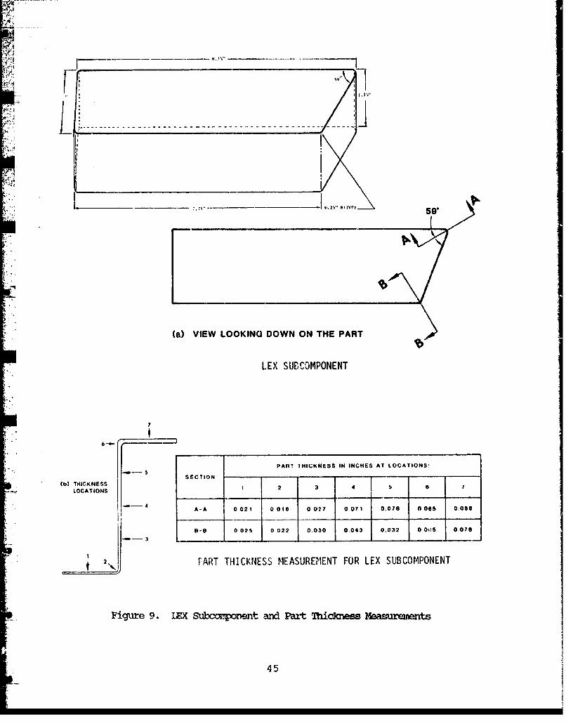
corner of acute angle and was found to be 0.015 inch. Figure9(b) shows thickness measurements at various locations of two
sections A-A and B-B. The maximum thickness strain on the formed
part was 500 percent.
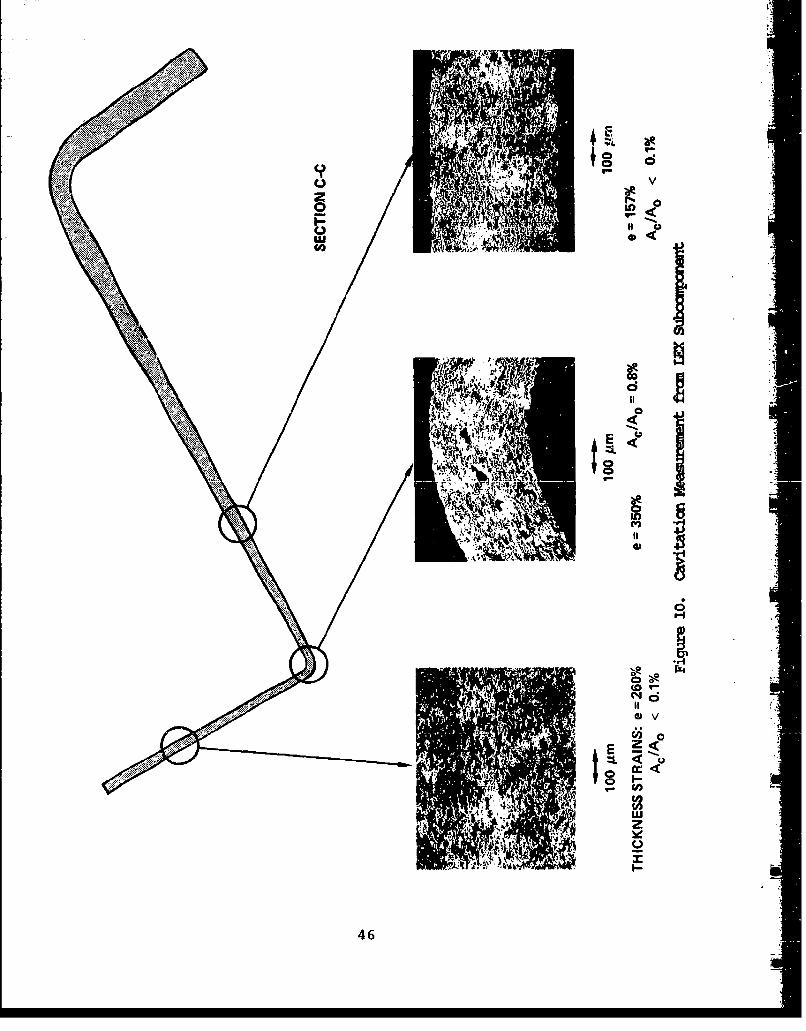
The formed part was'sectioned through the acute anglefor microstructural evaluations. Figure 10 shows the sectionalong with the optical micrographs at various locations. The
cavitation was measured using an image analyzer and is specified
as an area fraction. At 350 percent thickness strain location,the area fraction of cavities was 0.8 percent.
4.2 AV±ONICS DECK PRODUCIBIlITY FORMING TESTS
The outer and inner skins in the selected avionics deck
represent a simple SPF forming and do not require producibility
forming tests. The waffle pan, however, has a complex geometry
and square deep pockets with a 15 degree draft angle on thewalls. The most critical pocket was selected for producibility
forming tests. The geometry of the selected pocket is shown in
Figure 11. The tool for the subcomponent was machined from 4340
steel and was a self-contained unit with gas inlets and outlets.
Two subcomponents, one from 0.125-inch thick M7475
sheet and the other from 0.090-inch thick MD234, were fabricated.
Superplastic forming was carried out at 970 ±10°F and at a strain
rate of 3 x 10⁻⁴ sec- 1 ; with 400 psi back pressure. Reynolds
44
5 59
(a) VIEW LOOKING DOWN ON THE PART
LEX SUCCOMPONENT
7
6-
PART THICKNESS IN INCHES AT LOCATIONS:
SECTION . .... ..
(b) THICKNESS:,-•.-. ~LOCATIONS 12
_4I
3
A-A 0021 0 o02? 0.071 o0o.0 moss 0.086
"6-8 0.025 0 022 0.030 0.043 0.032 0.005 0.070
- 3 0_______ _____ __________ _____ _____
2 •FART THICKNESS MEASUREMENT FOR LEX SUBCOMPONENT
Figure 9. LEX Subcc.o)-ent and Part Thickness Mezamrments
45
LI-
. 0
0j
46H
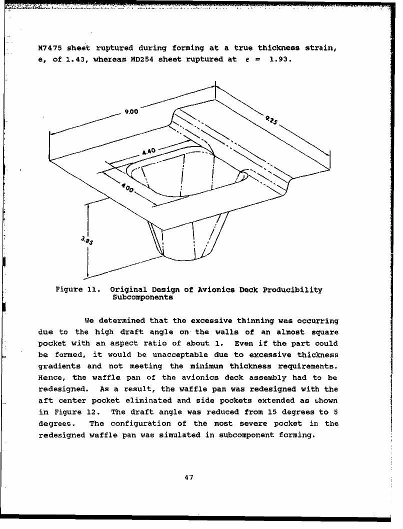
M7475 sheet ruptured during forming at a true thickness strain,
e, of 1.43, whereas MD254 sheet ruptured at e = 1.93.
9.00 ••
4..0
11 0
Figure 11. Original Design of Avionics Deck ProducibilitySubcomponents
We determined that the excessive thinning was occurring
due to the high draft angle on, the walls of an almost square
pocket with an aspect ratio of about 1. Even if the part could
be formed, it would be unacceptable due to excessive thicknessgradients and not meeting the minimum thickness requirements.
Hence, the waffle pan of the avionics deck assembly had to be
redesigned. As a result, the waffle pan was redesigned with the
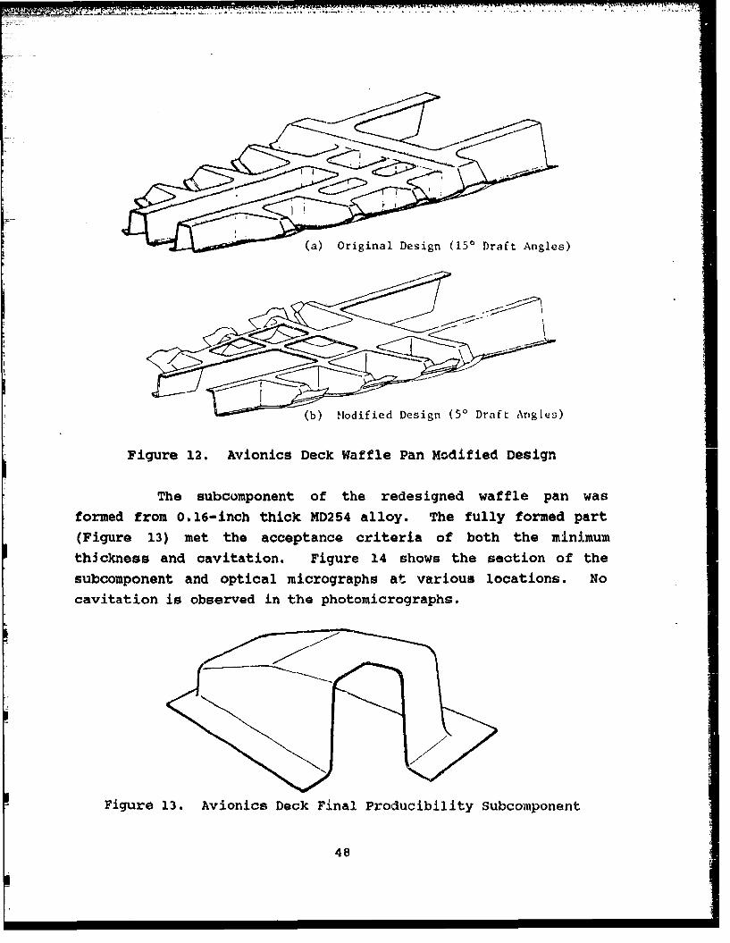
aft center pocket eliminated and side pockets extended as shownin Figure 12. The draft angle was reduced from 15 degrees to 5
degrees. The configuration of the most severe pocket in the
redesigned waffle pan was simulated in subcomponent forming.
47
~.N~-N
(a) Original Design (150 Draft Angles)
(b) I-odified Design (50 Draft An~gles)
Figure 12. Avionics Deck Waffle Pan Modified DeSign
The sub~cumponent of the redesigned waffle pan was
formed from 0.16.-inch thick MD254 alloy. The fully formed part(Figure 13) met the acceptance criteria of both the minimum
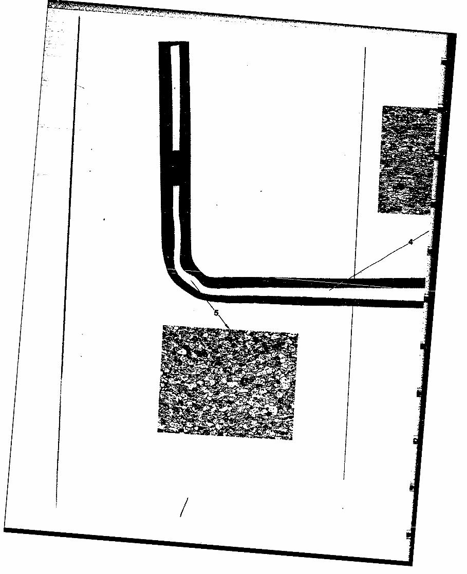
th~ckness and cavitation. Figure 14 shows the section of thesubcomponent and optical micrographs at various locations. No
cavitation is observed in the photomuicrographs.
Figure 13. Avionics Deck Final Producibility Subcomponent
48
... ....

AVIONICS DECK - SUSCOMPONEN
-- .. ....

.1.
Figure 14. Avionics Deck Subcomponent Miicrostructure
'.39
4.3 COMPONENT MODIFICATIONS 1"
Based on the results of producibility forming tests, a
component redesign may be necessary in certain cases. This will
be the case when new materials are introduced in SPF production.
Modifications had to be made in the design of LEX and waffle pan,
based on the forming tests, to ensure that thickness requirements
were met and no cavitation occurred in critical forming areas.
Based on the small cavitation and thickness measure-
ments observed in the LEX subcomponent, the corner radius was
increased from 0.25 to 0.375 inch.
The subcomponent forming of the avionics deck clearly
indicated that the original waffle pan design was not feasible
for SPF production. As discussed earlier, necessary modifica-
tions were made in the design to ensure the forming feasibility
and design requirements.
Once the forming feasibility tests have been success-
fully completed, the component design was finalized and tooling
concepts developed for full scale production.
51i

LE F T I N T E N T I1O N A L L Y B L A N K
52

SECTION 5
PARTS FABRICATION, ASSEMBLY AMDTESZTING
The LEX and avionics deck full scale structural parts
were superplastically formed using the tooling and fabrication
concepts developed in the producibility forming task. Reynolds
MD254 aluminum alloy was used for fabricating all SPF parts. One
LEX component (corrugation) and three avionics deck components(outer skin, inner skin and waffle pan) were superplastically
formed. The fabrication, assembly and testing of the parts is
briefly described in the following paragraphs.
5.1 LEADING EDGE EXTENSION (LEX)
The LEX corrugation tool was profile machined from 4340steel. It was a self-contained tool with seal edge and inlet-
outlet gas tubes. Multi part gas inlet-outlet holes were used to
prevent gas entrapment and for venting out the gas after forming.
The tool and the aluminum sheet were coated with boron
nitride prior to forming. The superplastic forming was done at
temperatures of 940 to 9806F. The tool was heated to the formingtemperature and 0.090-inch thick MD254 aluminum sheet was hot
loaded. The forming was done with a back pressure of 400 psi and
a theoretical strain rate of 2 x 10⁻⁴ sec"1 . The average strain
rate measured was 1.4 x 10⁻⁴ sec"1 .
The LEX corrugation was heat-treated to T6 tempersubsequent to the forming. The heat-treatment was verified
through electrical conductivity and hardness measurements. Afterheat-treatment, the SPF corrugations were chemically cleaned,
53

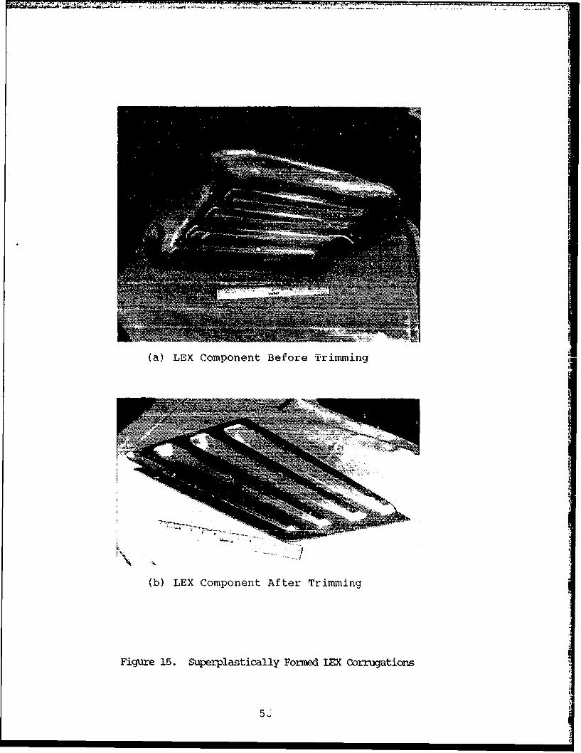
anodized and primed. A typical LEX corrugation formed is shownin Figure 15. A total of three parts were formed without anyfailures.
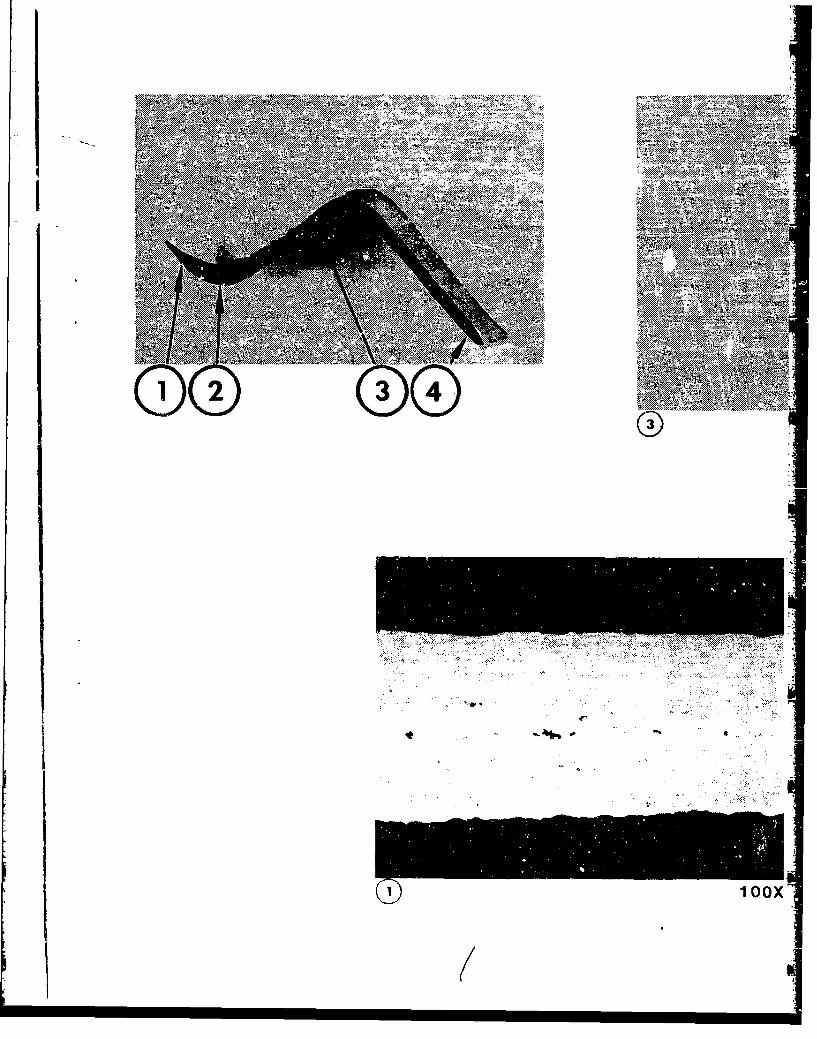
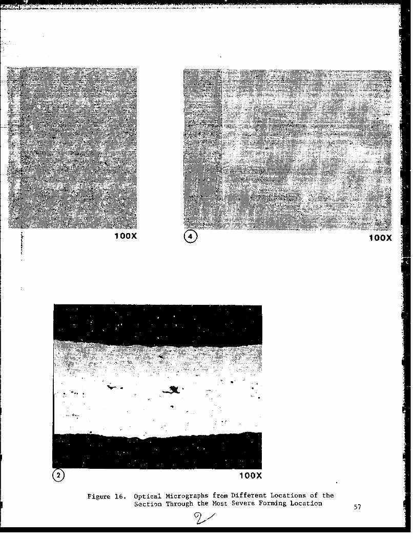
Figure 16 shows a section of deepest channel end andoptical micrographs from different locations on the section.There were a few areas containing isolated cavities, perhaps dueto the variation in material grain structure. However, the areafraction of these cavities was less than 0.5 percent.
5.2 A NSZQK
The avionics deck final assembly consisted of three SPFdetails, namely, (1) outer skin, (2) inner skin, and (3) wafflepan. The fabrication of these parts is discussed in the follow-ing paragraphs.
5.2.1 Fabrication of Ouiter and Inner Skins
The outer and inner skins were superplastically formedfrom 0.040-inch thick MD254 aluminum sheet. The forming was doneat a rate of 2 x 10⁻⁴ sec"1 in the temperature range of 943 to977"F with 400 psi back pressure. Three outer and three innerskins were successfully formed with no scrap parts. The SPFouter skin and inner skin parts are shown in Figures 17 and 18,respectively.
5.2.2 Waffle Pan Fabrication
Waffle pans were superplastically formed from 0.160-inch thick MD254 aluminum sheet. A forming strain rate of 1 x10⁻⁴ sec-1 was selected due to severe forming associated with the -
waffle pan. Six parts were superplastically formed withoutrupturing any part. A typical SPF waffle pan is shown in Figure19. Thickness measurements were taken from five parts to deter-mine the thinning variation. Typical thickness data are shown
54
bchb. .~ .WdcJ .~~ ..~.- . .0 .a ------- . * .., ..c *. ... d
(a) LEX Component Before Trimming
. . .. . .. . .. ..
(b) LEX Component After Trimming
Figure 15. Superplastically Formed LEX Corrugations
•'-- h.*' • •7&f• U-• • ,• •£• • ••41 ' '••"••''• • "T -'-• •a" • •r E""-'- • - . , ww • : r • ms i rr• -ir;rr--. ;.. r-• rr• • ,:... .---- •" --------• 'y'.....• -r-•-- r•° - rr• -- r .- '-rr--•:6••.-
LEFT INTENTIONALLY BLANK
I5
P. z
~~-WA
RE
M.6. Mi FIN" .MON,- A-->
1NOO
(R
ý%M;
•j ,bia l.t A b:..:.,q. * kb .. I,&.... * :. .. l...a ha t..mI -::•.:.• •.. I ,•-''i• I-
tN 0...,•,- v.*• . .... ..... , ,..: : 2r.].:-::. &.,× >.:,::. .....:::>:
- S.:....::.-.... c. ... 4.. 0. .. , 4 r .. ,.0, ~ ,. .. .,~
4..• , ,_,_..:.. :::...._..:: :..: :-...... .:. •....; ... '...• . • 1.0i.VS
-N--
_ : ..... ' : .
Vt". 0o
2 1r, 0 -4
orx
,..:. :-A, :: . -:::,,:....:.4:.:>,::. .: .::.:o...: :: :.:. :. ,.:. :. ..... , ...p., %t7 ; ...'"..: 0: " .9'4: ".::&.' "'"6j'0':"4::'::',:.:':"" .':.'.::'' :' :' ": 4 o... >'.:....' ...: " ,'':"'"".. :" :] ::
... • ....'o...:..A .':.4:.".::. .4.n:'% "' -'-" .".[7.". .. -'4 ''4 ".•:,:... ."
0• . , '.• .4.:"•:'' .' . :,' .:. 4.:•. . .:..,.: ..... : > ::•.:... ....
box1 0 bo
Figure 16. Optical Micrographs from Different Locations of theSection Through the Most Severe Forming Location 5
c z x:::::: :::::::::::::":"".':':.: :::.!.:!: :'::."":' : '[:i... . .•.[::" • '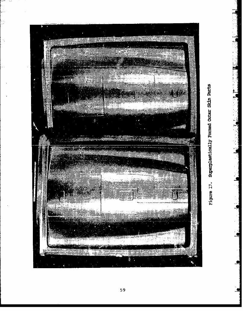
ýAIdu
-4
59
..... ...
60

gut =..
,*- 1_15 7777_ 7
N ''~..
1-
Figure 19. Avionics De&k Superplastically Formed Waffle Pan
1' 61

-in hFigure 20. The thickness variations between five parts werefound to be insignificant.
Optical microscopy was performed to determine cavita-tion at the areas of maximum elongation. Figure 21 shows atypical photomicrograph at a highly elongated location. Nocavitation is indicated by the photomicrographs.
5.3 DECK ASSEMBLY
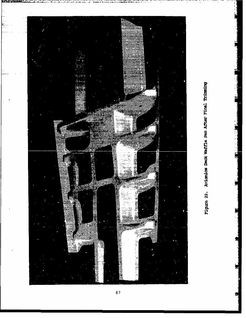
All the three SPF parts were heat-treated to T6 temperprior to deck assembly. The heat-treat was verified throughelectrical conductivity and hardness measurements. The three SPFparts were chem milled to remove excessive thickness and trimnedprior to the deck assembly. The waffle pan after chem millingand final trim is shown in Figure 22.
The final avionics deck assembly was completed usingthe rivet bonding concept. All three SPF parts and thesubstructural details were assembled utilizing the B.F. GoodrichA1444B paste adhesive. Application of rivets simulated thebonding pressure and simplified the curing process using an oveninstead of an autoclave. The completed avionics deck assembly isshown in Figure 23.
5.4 AVIONICS DECK TESTING
The structural testing of the SPF avionics deck wasconducted at the Air Force Wright Aeronautical Laboratories,testing facilities at Wright-Patterson Air Force Base. A detailedstructural test plan was prepared by Northrop and reviewed by AirForce test personnel. The details of load conditions, static test
and fatigue test are discussed in the following paragraphs.
62

0.10. 0916 0.094 0..5014
0.153 0.161409
0.157 0..13 .1456
0.5 0-13* 04 3 0.140 0.154 0.3*.1 .5
0.14034 0.1560.115
0.152e 20 .hcns Prfl14SF at~ a
1). 1g .63
LEFT I N TENT I ONA L LY BLANK
64

I sox
Im ON 096
I' MA~*~
AR__ -W
25O
.11
rigur*e 21. OpticalWaffle

mw
Zi
EM-
. ...'.7 ... &250X
50
Figure 21. Optical Micrographs from the Deepest Coiner of theWaffle Pan Showing No Cavitation 65
I.
I0
I
eq
67
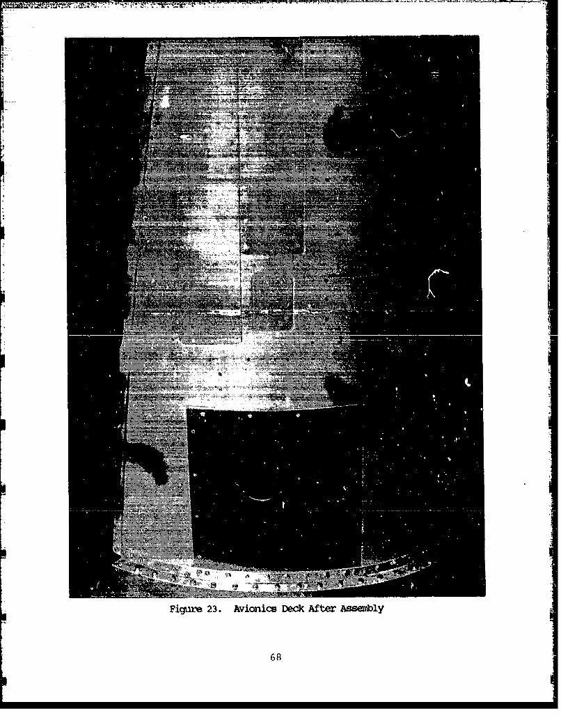
Figure 23. AVioniCS Deck After JASS~bY
68

5.44.1 Test Load Generation
The avionics deck is in the forward fuselage between
stations F.S. 47.50 and 87.50 of the F-S aircraft. The forward
fuselage structure between these stations is subjected to gun
blast pressure due to a gun barrel located on the left hand side
between the upper skin and the deck. In addition to the gun
blast pressure, the avionics deck is subjected to internal pres-
sure loading (cockpit pressure), external pressure loads and the
inertia loading of the structure and equipment. The deck is
designed for the following loads.
(1) Maximum cockpit bursting pressure of 3.98 psi.
(2) External air pressure linearly varying from a 1.4
psi collapsing pressure at F.S. 47.50 to a 0.8 psi
bursting pressure at F.S. 87.50 (bottom centerline
pressure for a symmetrical pull up under superson-
ic mach numbers).
(3) Inertia loading due to equipment assembled onto
the deck.
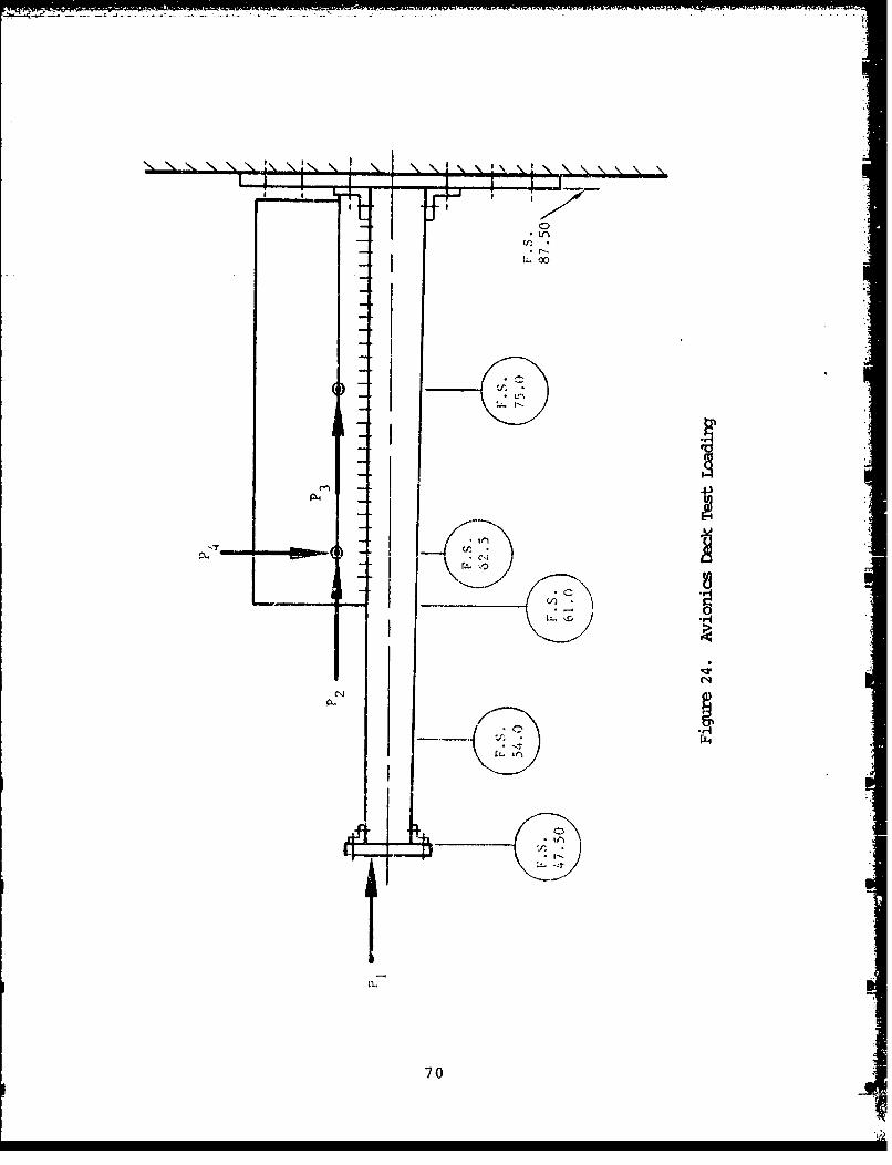
The avionics deck test loads were selected to satisfy
the flight load conditions. These loads were represented by four
reaction loads (Pj, P2 , P 3 and P 4 ) as shown in Figure 24. The
function of each load is described below.
P1 : To satisfy the upper and lower skin axial loadsbetween F.S. 47.50 and 62.50. This load, as shownin Figure 24, is applied slightly above the cen-
terline of the deck in order to distribute the
upper and lower skin axial loads in an Appropriate
manner.
69
-70

P2 : This load basically offsets the moment inducedtension loads of the upper skin. In addition,since this load is being applied above the deck,
it also contributes to the deck bending moment.
P3 : This load has basically the same function as P2
except it is applied at a different location. Thelocation of this reaction (F.S. 75.00) was alsoselected to satisfy the deck loading.
P4 : This load basically introduces the avionics deckshear load and has a great contribution towardsthe deck bending moments.
The values of these loads were selected to satisfy thedeck shear, moment and skin axial loads discussed before. Theultimate values of reaction loads were as follows:
P1 = 1500 lbs
P 2 = P 3 = 1000 lbs
P 4 = 600 lbs
5.4.2 Test Setup
Since testing of the avionics deck as an integral partof the F-5F forward fuselage structure was not feasible, certainmodifications were required in order to test the deck as anindividual component. The lower avionics deck was set up in sucha way that it simulates the actual loading of the lower deck box.An attempt was made to simulate the actual boundary conditions ofthe deck. Therefore, since the bending moments at the forwardend (F.S. 47.50) were minimal, and much higher at the aft end(F.S. 87.50); we decided to brick-wall the deck at the aft end
71
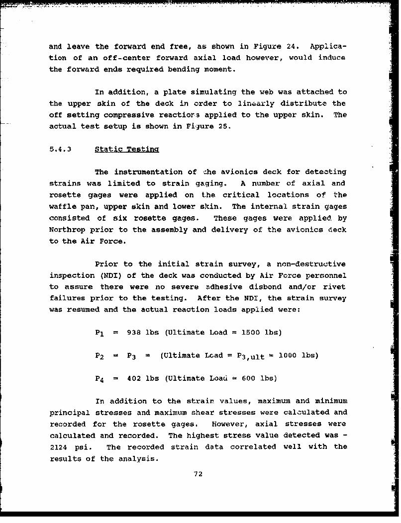
and leave the forward end free, as shown in Figure 24. Applica-tion of an off-center forward axial load however, would induce
the forward ends required bending moment.
In addition, a plate simulating the web was attached to
the upper skin of the deck in order to linearly distribute the
off setting compressive reactiors applied to the upper skin. The
actual test setup is shown in Figure 25.
5.4.3 Static Testing
The instrumentation of --he avionics deck for detecting
strains was limited to strain gaging. A number of axial androsette gages were applied on the critical locations of the
waffle pan, upper skin and lower skin. The internal strain gages
consisted of six rosette gages. These gages were applied by
Northrop prior to the assembly and delivery of the avionics deck
to the Air Force.
Prior to the initial strain survey, a non-destructive
inspection (NDI) of the deck was conducted by Air Force personnelto assure there were no severe adhesive disbond and/or rivetfailures prior to the testing. After the NDI, the strain survey
was resumed and the actual reaction loads applied were:
Pl = 938 lbs (Ultimate Load = 1500 ibs)
P2 = P3 = (Ultimate Load = P3,ult = 1000 ibs)
P4 = 402 lbs (Ultimate Load = 600 Ibs)
In addition to the strain values, maximum and minimum
principal stresses and maximum shear stresses were calculated and
recorded for the rosette gages. However, axial stresses were
calculated and recorded. The highest stress value detected was -
2124 psi. The recorded strain data correlated well with the
results of the analysis.
72
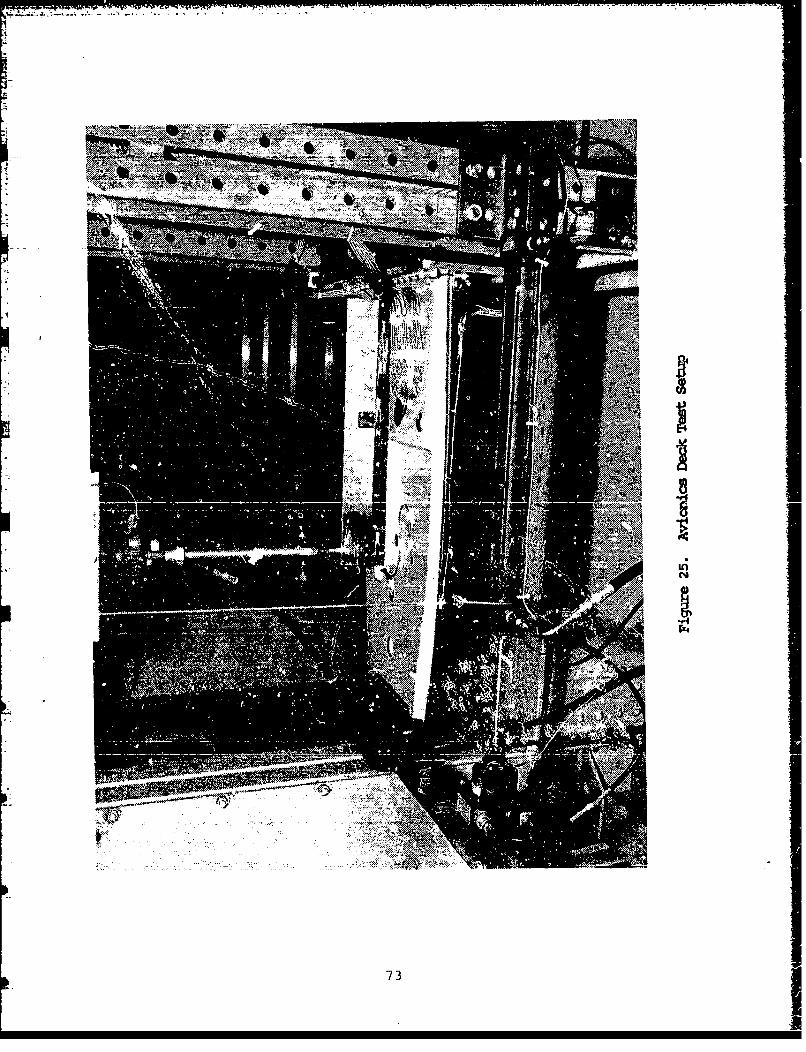
73
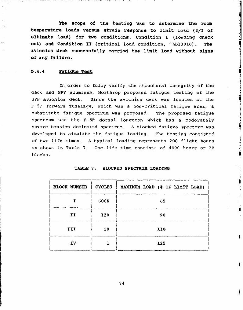
The scope of the testing was to determine the roomtemperature loads versus strain response to limit livtd (2/3 ofultimate load) for two conditions, Condition I (loAding checkout) and Condition II (critical load condition, 2AB13010). Theavionics deck successfully carried the limit load without signsof any failure.
5.4.4 4atigue Test
In order to fully verify the structural integrity of the
deck and SPF aluminum, Northrop proposed fatigue testing of the
SPF avionics deck. Since the avionics deck was located at theF-5F forward fuselage, which was a non-critical fatigue area, a
substitute fatigue spectrum was proposed. The proposed fatiguespectrum was the F-5F dorsal longeron which has a moderately
severe tension dominated spectrum. A blocked fatigue spectrum was
developed to simulate the fatigue loading. The testing consistcd
of two life times. A typical loading represents 200 flight hours
as shown in Table 7. One life time consists of 4000 hours or 20
blocks.
TABLE 7. BLOCKED SPECTRUM LOADING
BLOCK NUMBER CYCLES MAXIMUM LOAD (% OF LIMIT LOAD)
I 6000 65
II 120 90
III 20 110
IV 1 125
74

The subject fatigue schedule was designed by assuming
that each life time consisted of 4000 flight hours.
The avionics deck survived four life times of fatigue
loading. Subsequent to fatigue testing, the deck was subjected
to static load equivalent to twice the ultimate load. No failure
occurred at this load level, and there was no visible damage to
the deck.
75
LEFT INTENTIONALLY BLANK
7 "4

- f- -- . - '.
SECTION 6
SqUMEAY AND CONCLUS.IONS
6.1 SUMMARY
A five-phase program was carried out to exploit the
applications of SPF aluminum and develop and demonstrate the
process as a viable means of producing structural airframe parts
that are more efficient and cost effective than conventi onally
produced parts.
Several aluminum alloys were evaluated for their SPF
potential and Reynolds material MD254 was found to have the
highest SPF potential. The post-SPF mechanical properties of
this material were found to be comparable to 7075-T6 alrnninun.
Conceptual design studies were carried out to identify the parts
which will make full use of superplastic forming. The major
emphasis was on reduction of piece count and assembly costs. Two
components, namely, the LEX and avionics deck were selected and
redesigns' as SPF assemblies.
Producibility forming tests were conducted to assess the
forming feasibility of the components based on the initial desian
parameters. Based on the results of these tests, slight
modifications were made in the original SPF design to make sure
that rio cavlitation was formed, and minimum thickness requirements
were met during the fabrication of the SPF components.
The LEX corrugation and three SPF parts (outer skin,
inner sk'-in and waffle rzan) for the avionics deck were made with-
out any scrap parts. The avionics deck was assembled using rivet
bonding. The deck v.as tested under static and fatigue loading.
77
The deck was tested under static loadint to design
limit load and then tested under con-.tant amplitude fatigue
loading. Subsequent to two lifetimes of fatigue loading, the
deck was loaded to 200 percent of the design ultimate load with-
out failure.
6.2 CL..SIONS
1'.,, studies carried out in this program have resulted
in the following conclusions:
(a) Designing aircraft structural parts using SPF
technology can result in significant cost andweight savings.
(b) Supexplastic forming of complex components may re-
quire producibility forming tests on smaller
parts, simulating critical forming areas, to
assure the forming feasibility of complex parts.
(c) Slight design modifications in the design of SPF
parts may have to be made if the results of form-
ing feasibility tests indicate forming problems
such as cavitation in critical areas or not meet-
ing minimum thickness requirements.
(d) Post-SPF mechanical an,. crack growth properties of
7475-T6 material, f• :zied at 50 and 150 percent
strain, are comparable to conventional 7475-T6
material.
(e) Adhesive bonding, resistance seam welding and
weldbonding of post-SPF material do not representany probl'-a. The surface preparation and joining
irformation developed for 7075-T6 material can be
applied to post--SPF 7475 material.
78
SECTION 7
1. Mahoney, M. W. and Hamilton, C. H., "Superplastic Aluminum
Evaluation," AFWAL-TR-81-3051, Final Report on Air Force
Contract No. F33615-79-C-3218.
2. "Superplastic Formed Aluminum T-39 Frame, "Final Report of
Air Force Contract F33615-80-C-3240.
3. Zamani, H., Vastava, R., Agarwal, S. P., Final Contract
Report, Volume II.
4. Woodford, D. A., Transa.iLy_ , Vol. 62 (1969)
p. 291.
79

![Kinetics in Solid State Bonding of Superplastic Steel and ... · Acknowledgement ... A modified definition of solid state diffusion bonding, proposed by Kazakov [24], is described](https://img.pdfslide.tips/doc/110x75/5b00a3037f8b9a6a2e8cf92c/kinetics-in-solid-state-bonding-of-superplastic-steel-and-a-modified-definition.jpg)