Embed Size (px)
Citation preview
USE AND SERVICE MANUAL
OIL METER
P.D. METERS TYPE
LBM 1000 AND LBM 3000
H. HERMANN EHLERS H. HERMANN EHLERS H. HERMANN EHLERS H. HERMANN EHLERS GMBHGMBHGMBHGMBHFördern - Messen - Regeln - Dosieren - VerdichtenFördern - Messen - Regeln - Dosieren - VerdichtenFördern - Messen - Regeln - Dosieren - VerdichtenFördern - Messen - Regeln - Dosieren - Verdichten
Ingenieurbüro - WerksvertretungenIngenieurbüro - WerksvertretungenIngenieurbüro - WerksvertretungenIngenieurbüro - Werksvertretungen
An der Autobahn 45 ♦ 28876 Oyten ♦ Tel. 04207/91 21-0 ♦ Fax 04207/91 21 41 Email [email protected] ♦ Home http://www.durchflussmessen.de
CONTENTS
SECTION TITLE Page
1 Introduction 1
2 Operation 1
3 General rules for meters installation 2
4 Meters protection during storage periods 2
5 Meters dismounting and overhaul 3
6 Disassembly 3
7 Main components test and overhaul 5
8 Meters reassembly 6
9 Slacks’ table 7
10 Calibration mechanism 7
11 Calibration 8
12 Tests after overhaul 9
13 Suggested lubricating oils for calibrating mechanism 9
14 Mechanical counters 9
15 Special tools 10
ENCLOSED:
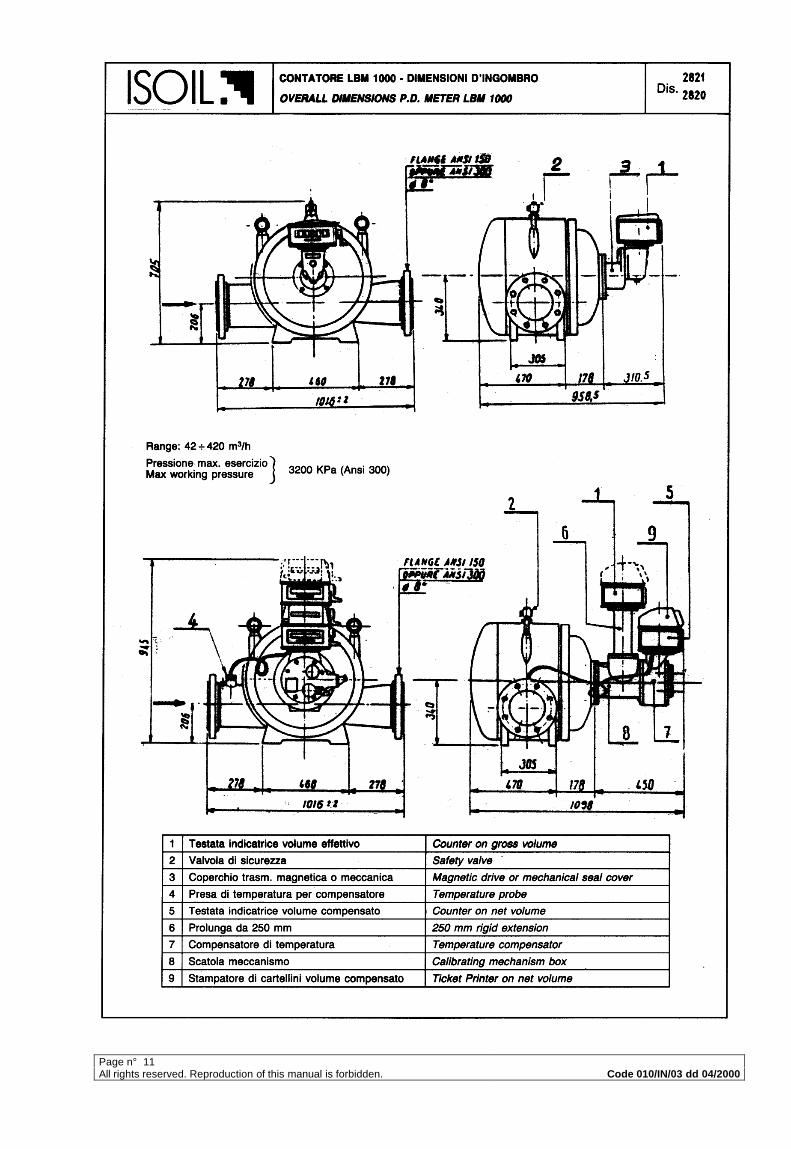
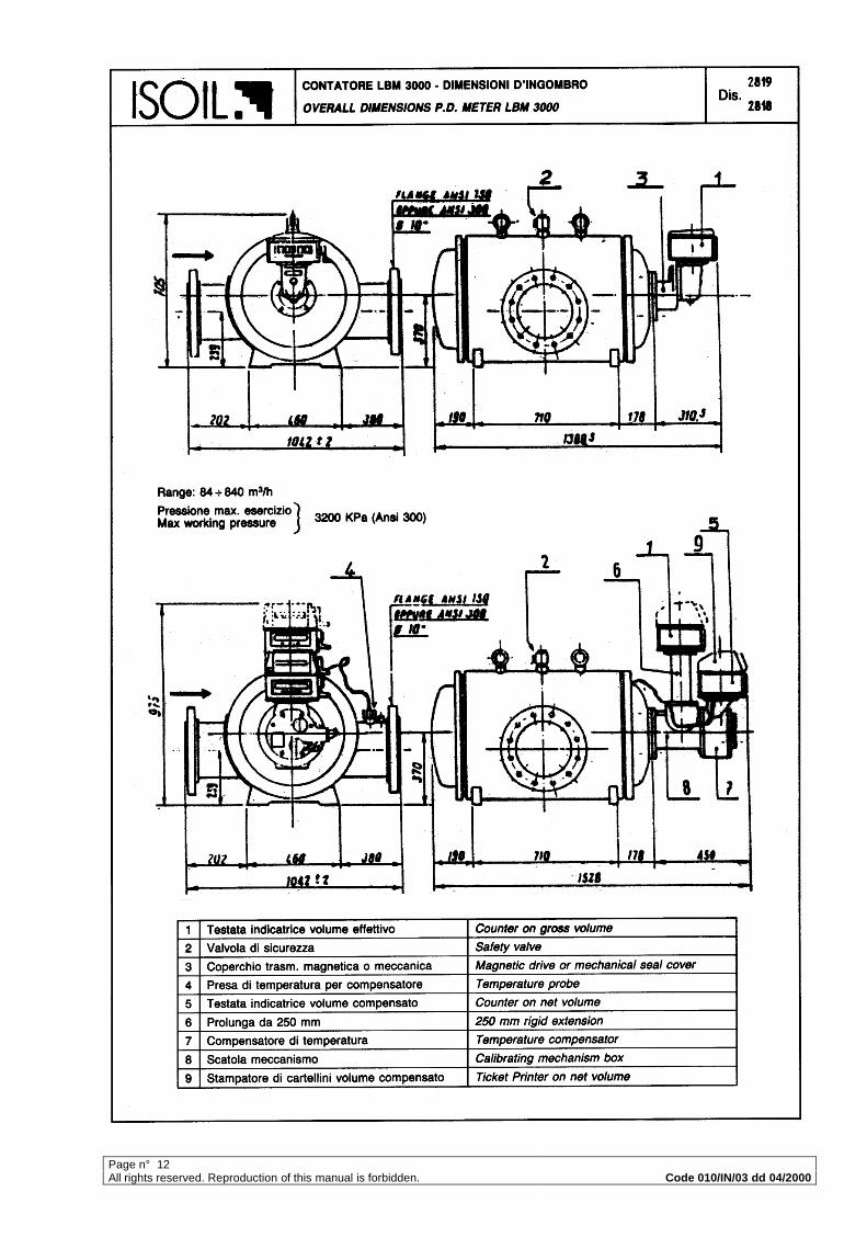
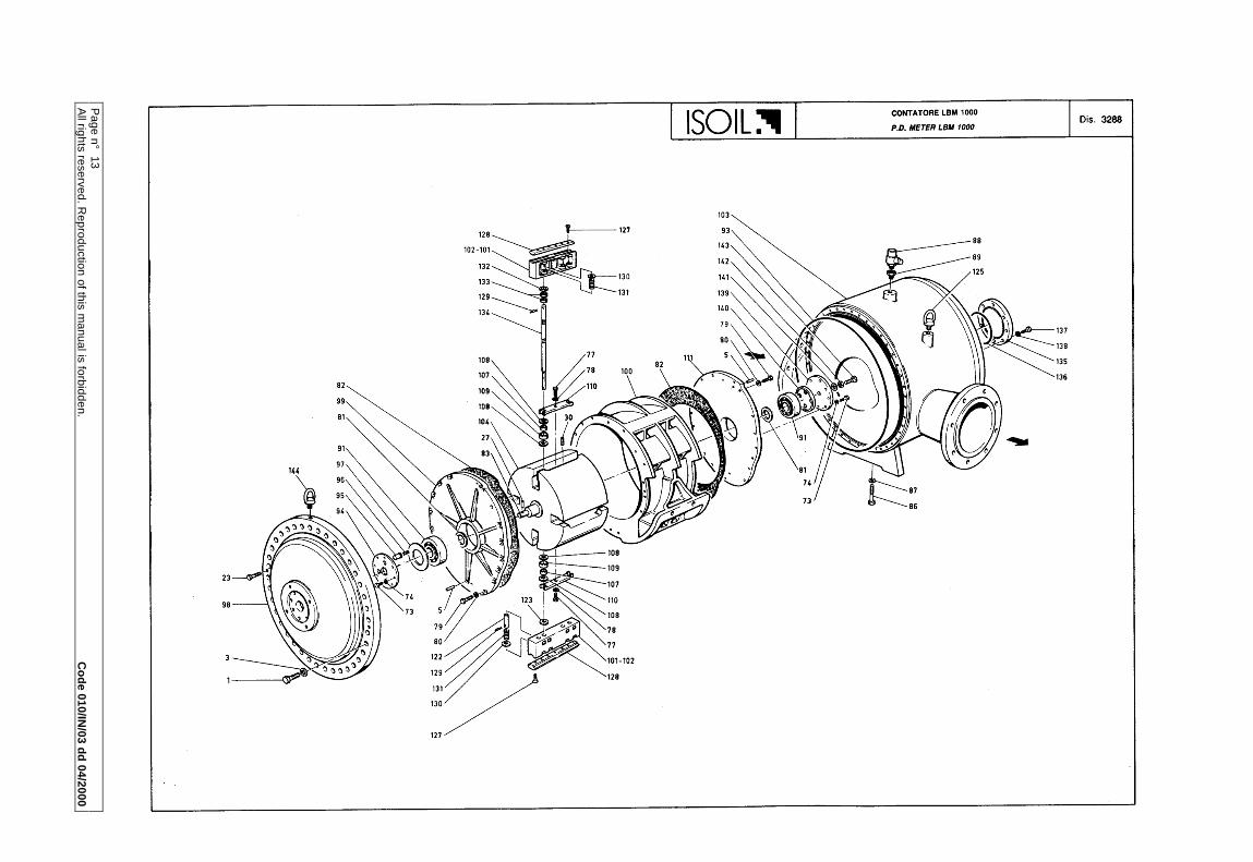
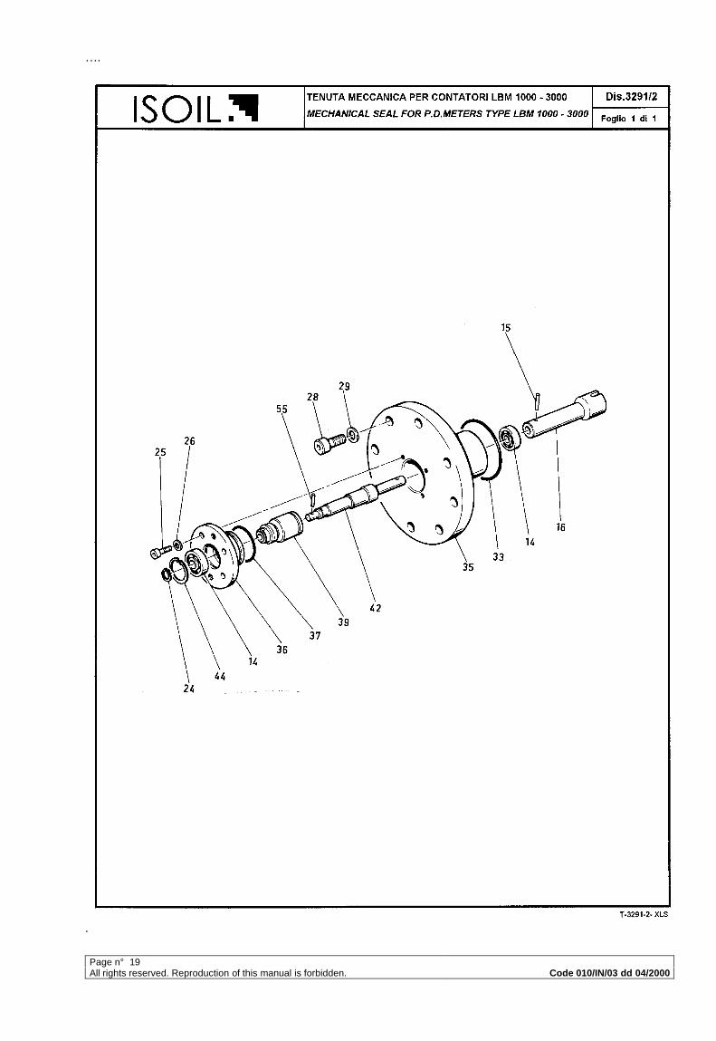
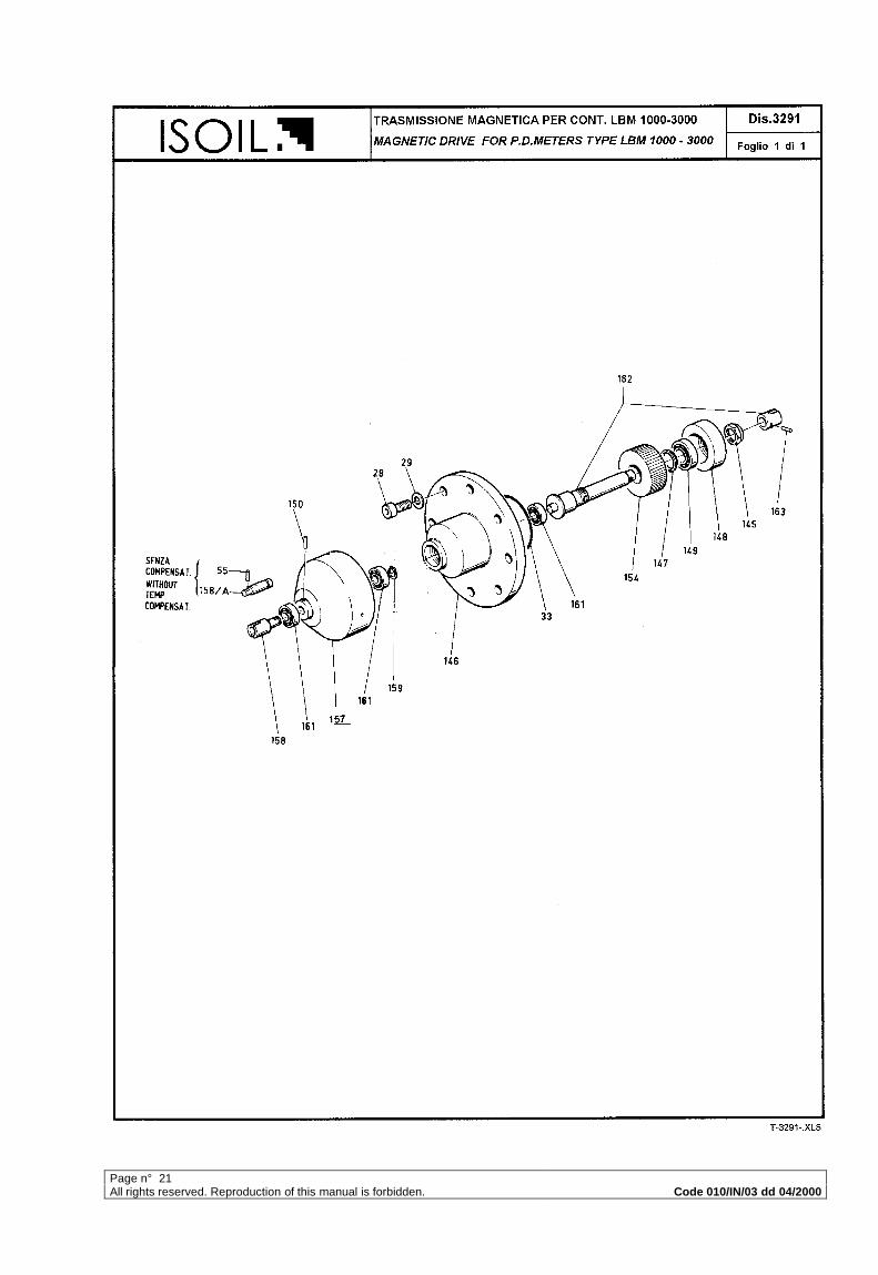
- Overall dimensions – P.d.meter type LBM 1000 Dwg. n. 2820-2821- Overall dimensions – P.d.meter type LBM 3000 Dwg. n. 2818-2819- Exploded view of LBM 1000 Dwg. n. 3288- Exploded view of LBM 3000 Dwg. n. 3287- Exploded view of mechanical seal Dwg. n. 3291/2- Exploded view of magnetic drive Dwg. n. 3291- Exploded view of calibrating mechanism and spacer Dwg. n. 3289- Exploded view of temperature compensator and spacer Dwg. n. 3290- Exploded view of spacer and calibration mechanism Dwg. n. 672/LBM- Gearing box for mounting with VEGA counter Dwg. n. 3958
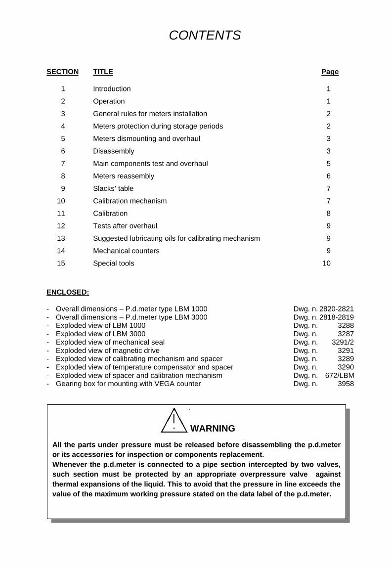
WARNING
All the parts under pressure must be released before disassembling the p.d.meteror its accessories for inspection or components replacement.Whenever the p.d.meter is connected to a pipe section intercepted by two valves,such section must be protected by an appropriate overpressure valve againstthermal expansions of the liquid. This to avoid that the pressure in line exceeds thevalue of the maximum working pressure stated on the data label of the p.d.meter.
Page n° 1All rights reserved. Reproduction of this manual is forbidden.. Code 010/IN/03 dd 04/2000
1 INTRODUCTION
"OIL METER" positive displacement meters are precision measuring instruments designedfor use with a variety of petrochemical products and liquids. Each meter is fully tested andcalibrated by factory before despatch, and a regular service will maintain a high standard ofperformance and accuracy.Special tools have been designed to facilitate overhaul operations and we stronglyrecommend their use (see page 10). If the accuracy of the meter varies beyond acceptedlimits or if mechanical defects appear, meter should be overhauled and recalibrated.Experience has shown that mechanical defects are usually caused by the entry of foreignmatters into the metering compartment due to inadequate straining facilities in the pipeline.It is most important therefore that an efficient strainer is installed in the system and inspectedat regular intervals to insure a correct functioning.
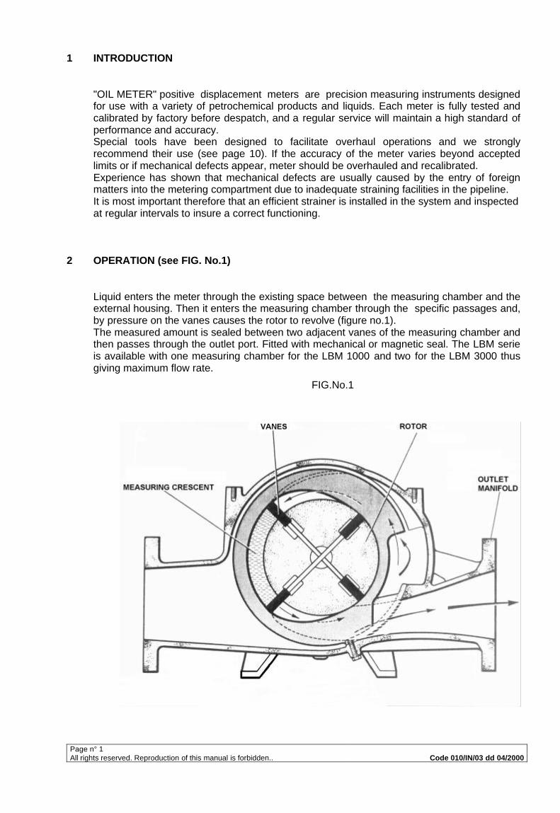
2 OPERATION (see FIG. No.1)
Liquid enters the meter through the existing space between the measuring chamber and theexternal housing. Then it enters the measuring chamber through the specific passages and,by pressure on the vanes causes the rotor to revolve (figure no.1).The measured amount is sealed between two adjacent vanes of the measuring chamber andthen passes through the outlet port. Fitted with mechanical or magnetic seal. The LBM serieis available with one measuring chamber for the LBM 1000 and two for the LBM 3000 thusgiving maximum flow rate.
FIG.No.1
Page n° 2All rights reserved. Reproduction of this manual is forbidden. Code 010/IN/03 dd 04/2000
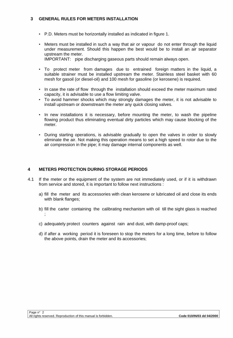
3 GENERAL RULES FOR METERS INSTALLATION
• P.D. Meters must be horizontally installed as indicated in figure 1.
• Meters must be installed in such a way that air or vapour do not enter through the liquidunder measurement. Should this happen the best would be to install an air separatorupstream the meter.IMPORTANT: pipe discharging gaseous parts should remain always open.
• To protect meter from damages due to entrained foreign matters in the liquid, asuitable strainer must be installed upstream the meter. Stainless steel basket with 60mesh for gasoil (or diesel-oil) and 100 mesh for gasoline (or kerosene) is required.
• In case the rate of flow through the installation should exceed the meter maximum ratedcapacity, it is advisable to use a flow limiting valve.
• To avoid hammer shocks which may strongly damages the meter, it is not advisable toinstall upstream or downstream the meter any quick closing valves.
• In new installations it is necessary, before mounting the meter, to wash the pipelineflowing product thus eliminating eventual dirty particles which may cause blocking of themeter.
• During starting operations, is advisable gradually to open the valves in order to slowlyeliminate the air. Not making this operation means to set a high speed to rotor due to theair compression in the pipe; it may damage internal components as well.
4 METERS PROTECTION DURING STORAGE PERIODS
4.1 If the meter or the equipment of the system are not immediately used, or if it is withdrawnfrom service and stored, it is important to follow next instructions :
a) fill the meter and its accessories with clean kerosene or lubricated oil and close its endswith blank flanges;
b) fill the carter containing the calibrating mechanism with oil till the sight glass is reached;
c) adequately protect counters against rain and dust, with damp-proof caps;
d) if after a working period it is foreseen to stop the meters for a long time, before to followthe above points, drain the meter and its accessories;
Page n° 3All rights reserved. Reproduction of this manual is forbidden. Code 010/IN/03 dd 04/2000
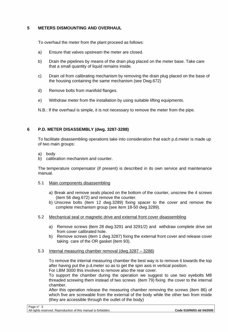
5 METERS DISMOUNTING AND OVERHAUL
To overhaul the meter from the plant proceed as follows:
a) Ensure that valves upstream the meter are closed.
b) Drain the pipelines by means of the drain plug placed on the meter base. Take carethat a small quantity of liquid remains inside.
c) Drain oil from calibrating mechanism by removing the drain plug placed on the base ofthe housing containing the same mechanism (see Dwg.672)
d) Remove bolts from manifold flanges.
e) Withdraw meter from the installation by using suitable lifting equipments.
N.B.: If the overhaul is simple, it is not necessary to remove the meter from the pipe.
6 P.D. METER DISASSEMBLY (dwg. 3287-3288)
To facilitate disassembling operations take into consideration that each p.d.meter is made upof two main groups:
a) bodyb) calibration mechanism and counter.
The temperature compensator (if present) is described in its own service and maintenancemanual.
5.1 Main components disassembling
a) Break and remove seals placed on the bottom of the counter, unscrew the 4 screws(item 56 dwg.672) and remove the counter.
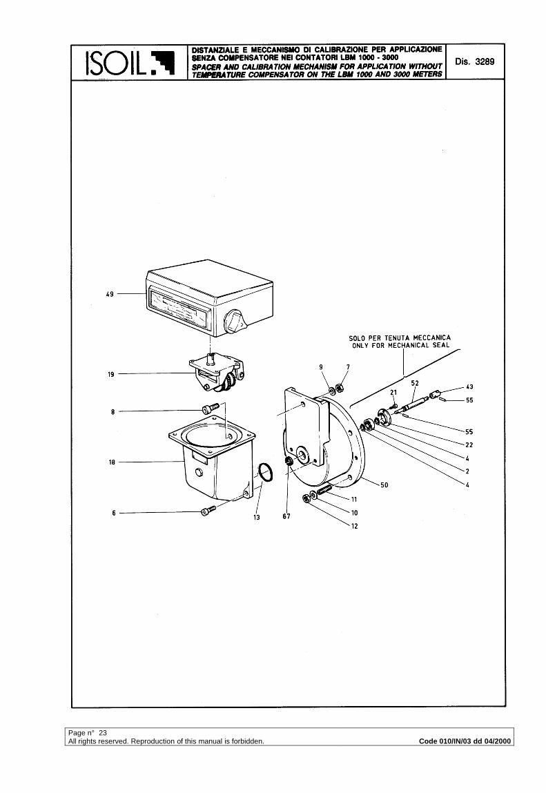
b) Unscrew bolts (item 12 dwg.3289) fixing spacer to the cover and remove thecomplete mechanism group (see item 18-50 dwg.3289).
5.2 Mechanical seal or magnetic drive and external front cover disassembling
a) Remove screws (item 28 dwg.3291 and 3291/2) and withdraw complete drive setfrom cover calibrated hole.
b) Remove screws (item 1 dwg.3287) fixing the external front cover and release covertaking care of the OR gasket (item 93).
5.3 Internal measuring chamber removal (dwg.3287 – 3288)
To remove the internal measuring chamber the best way is to remove it towards the topafter having put the p.d.meter so as to get the spin axis in vertical position.For LBM 3000 this involves to remove also the rear cover.To support the chamber during the operation we suggest to use two eyebolts M8threaded screwing them instead of two screws (item 79) fixing the cover to the internalchamber.After this operation release the measuring chamber removing the screws (item 86) ofwhich five are screwable from the external of the body while the other two from inside(they are accessible through the outlet of the body)
Page n° 4All rights reserved. Reproduction of this manual is forbidden. Code 010/IN/03 dd 04/2000
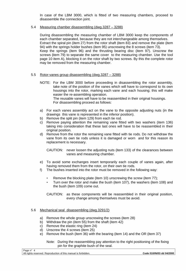
In case of the LBM 3000, which is fitted of two measuring chambers, proceed todisassemble the connection joint.
5.4 Measuring chamber disassembling (dwg.3287 – 3288)
During disassembling the measuring chamber of LBM 3000 keep the components ofeach chamber separated, because they are not interchangeable among themselves.Extract the spiral pin (item 27) from the rotor shaft (item 83) and remove the plate (item94) with the springs holder bushes (item 95) unscrewing the 8 screws (item 73).Keep the springs (item 96) and the thrusting bearing disc (item 97). Unscrew thescrews (item 79) to separate the same cover to the measuring chamber. Use the toolpage 10 item A), blocking it on the rotor shaft by two screws. By this the complete rotormay be removed from the measuring chamber.
5.5 Rotor-vanes group disassembling (dwg.3287 – 3288)
NOTE: For the LBM 3000 before proceeding in disassembling the rotor assembly,take note of the position of the vanes which will have to correspond to its ownhousings into the rotor, marking each vane and each housing; this will makeeasier the re-assembling operation.The reusable vanes will have to be reassembled in their original housings.For disassembling proceed as follows:
a) For each vanes assembly act on the vane to the opposite adjusting nuts (in thedrawings this vane is represented in the inferior position).
b) Remove the split pin (item 129) from each tie rod.c) Remove paying attention the remaining vane fitted with two washers (item 136)
taking into consideration that these last ones will have to be reassembled in theiroriginal position.
d) Remove from the rotor the remaining vane fitted with tie rods. Do not withdraw thevane from its own tie rods unless it is damaged or worn and for this reason itsreplacement is necessary.
CAUTION: never loosen the adjusting nuts (item 133) of the clearances betweenvanes and measuring chamber.
e) To avoid some exchanges insert temporarily each couple of vanes again, afterhaving removed them from the rotor, on their own tie rods.
f) The bushes inserted into the rotor must be removed in the following way:
• Remove the blocking plate (item 10) unscrewing the screw (item 77);• Turn over the rotor and make the bush (item 107), the washers (item 108) and
the bush (item 109) come out.
CAUTION: as these components will be reassembled in their original position,every change among themselves must be avoid.
5.6 Mechanical seal disassembling (dwg.3291/2)
a) Remove the whole group unscrewing the screws (item 28)b) Withdraw the pin (item 55) from the shaft (item 42)c) Remove the elastic ring (item 24)d) Unscrew the 4 screws (item 25)e) Remove the bush (item 36) with the bearing (item 14) and the OR (item 37)
Note: During the reassembling pay attention to the right positioning of the fixingpin for the graphite bush of the seal.
Page n° 5All rights reserved. Reproduction of this manual is forbidden. Code 010/IN/03 dd 04/2000
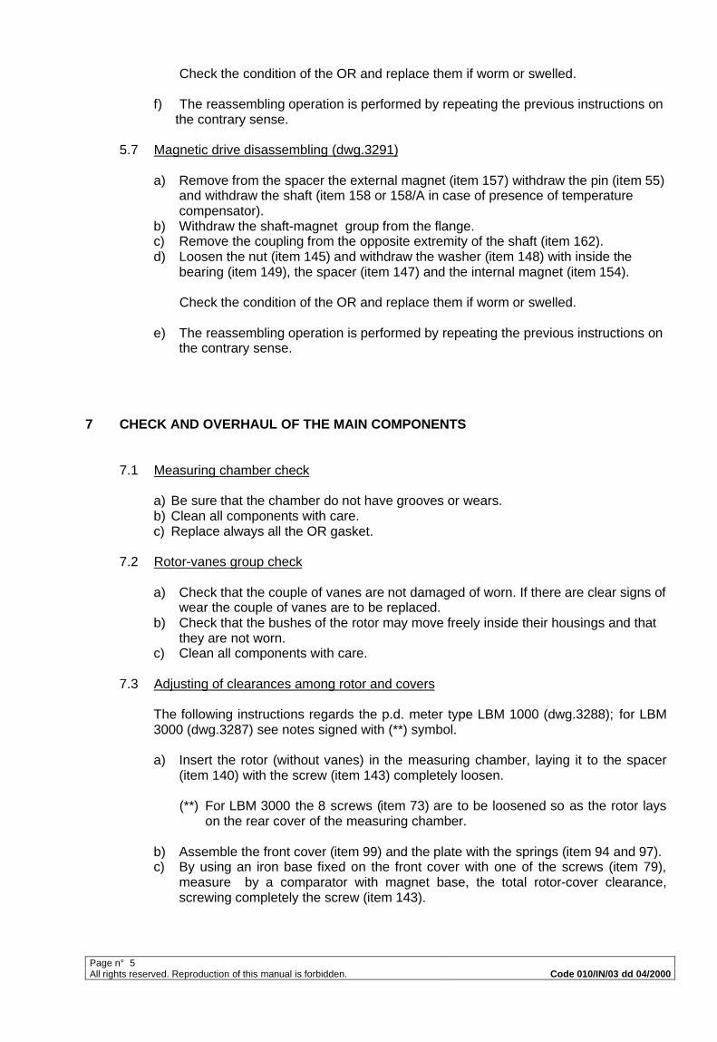
Check the condition of the OR and replace them if worm or swelled.
f) The reassembling operation is performed by repeating the previous instructions onthe contrary sense.
5.7 Magnetic drive disassembling (dwg.3291)
a) Remove from the spacer the external magnet (item 157) withdraw the pin (item 55)and withdraw the shaft (item 158 or 158/A in case of presence of temperaturecompensator).
b) Withdraw the shaft-magnet group from the flange.c) Remove the coupling from the opposite extremity of the shaft (item 162).d) Loosen the nut (item 145) and withdraw the washer (item 148) with inside the
bearing (item 149), the spacer (item 147) and the internal magnet (item 154).
Check the condition of the OR and replace them if worm or swelled.
e) The reassembling operation is performed by repeating the previous instructions onthe contrary sense.
7 CHECK AND OVERHAUL OF THE MAIN COMPONENTS
7.1 Measuring chamber check
a) Be sure that the chamber do not have grooves or wears.b) Clean all components with care.c) Replace always all the OR gasket.
7.2 Rotor-vanes group check
a) Check that the couple of vanes are not damaged of worn. If there are clear signs ofwear the couple of vanes are to be replaced.
b) Check that the bushes of the rotor may move freely inside their housings and thatthey are not worn.
c) Clean all components with care.
7.3 Adjusting of clearances among rotor and covers
The following instructions regards the p.d. meter type LBM 1000 (dwg.3288); for LBM3000 (dwg.3287) see notes signed with (**) symbol.
a) Insert the rotor (without vanes) in the measuring chamber, laying it to the spacer(item 140) with the screw (item 143) completely loosen.
(**) For LBM 3000 the 8 screws (item 73) are to be loosened so as the rotor layson the rear cover of the measuring chamber.
b) Assemble the front cover (item 99) and the plate with the springs (item 94 and 97).c) By using an iron base fixed on the front cover with one of the screws (item 79),
measure by a comparator with magnet base, the total rotor-cover clearance,screwing completely the screw (item 143).
Page n° 6All rights reserved. Reproduction of this manual is forbidden. Code 010/IN/03 dd 04/2000
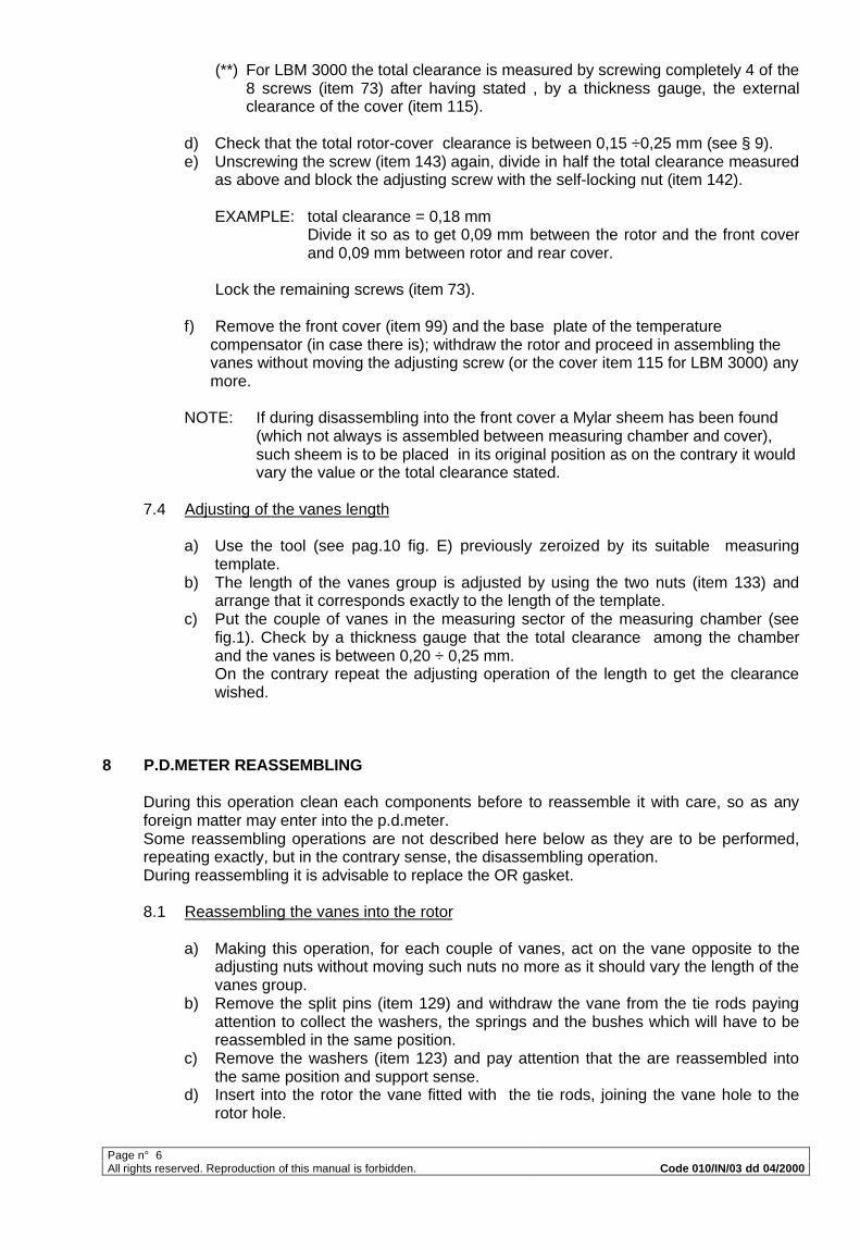
(**) For LBM 3000 the total clearance is measured by screwing completely 4 of the8 screws (item 73) after having stated , by a thickness gauge, the externalclearance of the cover (item 115).
d) Check that the total rotor-cover clearance is between 0,15 ÷0,25 mm (see § 9).e) Unscrewing the screw (item 143) again, divide in half the total clearance measured
as above and block the adjusting screw with the self-locking nut (item 142).
EXAMPLE: total clearance = 0,18 mmDivide it so as to get 0,09 mm between the rotor and the front coverand 0,09 mm between rotor and rear cover.
Lock the remaining screws (item 73).
f) Remove the front cover (item 99) and the base plate of the temperaturecompensator (in case there is); withdraw the rotor and proceed in assembling thevanes without moving the adjusting screw (or the cover item 115 for LBM 3000) anymore.
NOTE: If during disassembling into the front cover a Mylar sheem has been found(which not always is assembled between measuring chamber and cover),such sheem is to be placed in its original position as on the contrary it wouldvary the value or the total clearance stated.
7.4 Adjusting of the vanes length
a) Use the tool (see pag.10 fig. E) previously zeroized by its suitable measuringtemplate.
b) The length of the vanes group is adjusted by using the two nuts (item 133) andarrange that it corresponds exactly to the length of the template.
c) Put the couple of vanes in the measuring sector of the measuring chamber (seefig.1). Check by a thickness gauge that the total clearance among the chamberand the vanes is between 0,20 ÷ 0,25 mm.On the contrary repeat the adjusting operation of the length to get the clearancewished.
8 P.D.METER REASSEMBLING
During this operation clean each components before to reassemble it with care, so as anyforeign matter may enter into the p.d.meter.Some reassembling operations are not described here below as they are to be performed,repeating exactly, but in the contrary sense, the disassembling operation.During reassembling it is advisable to replace the OR gasket.
8.1 Reassembling the vanes into the rotor
a) Making this operation, for each couple of vanes, act on the vane opposite to theadjusting nuts without moving such nuts no more as it should vary the length of thevanes group.
b) Remove the split pins (item 129) and withdraw the vane from the tie rods payingattention to collect the washers, the springs and the bushes which will have to bereassembled in the same position.
c) Remove the washers (item 123) and pay attention that the are reassembled intothe same position and support sense.
d) Insert into the rotor the vane fitted with the tie rods, joining the vane hole to therotor hole.
Page n° 7All rights reserved. Reproduction of this manual is forbidden. Code 010/IN/03 dd 04/2000
e) Check by a thickness gauge that the clearance between rotor hole and vane isincluded between 0,20 ÷ 0,25 mm.
f) Reassemble on the opposite side the vane previously kept away repeating on thecontrary the operation previously stated.
8.2 Reassembling of the rotor fitted with vanes (dwg.3288)
a) Insert the rotor in the measuring chamber laying its external surface in the sector ofthe measuring chamber having the minimum bending radius.
b) Reassemble the front cover finishing in such way the assembling of the internalchamber.
8.3 Assembling finishing
The reassembling of the meter is completed when the measuring chamber is insertedagain into the external body.
(**) For LBM 3000 the operation included also the timing of the flange of the connectionjoint among the two chambers. This operation causes the alignment of the tworeference signes stated on the rotor shaft and on the semi-joint (see also notes ondwg.3287)On inserting the second chamber take care to engage rightly the semi-joints amongthemselves.
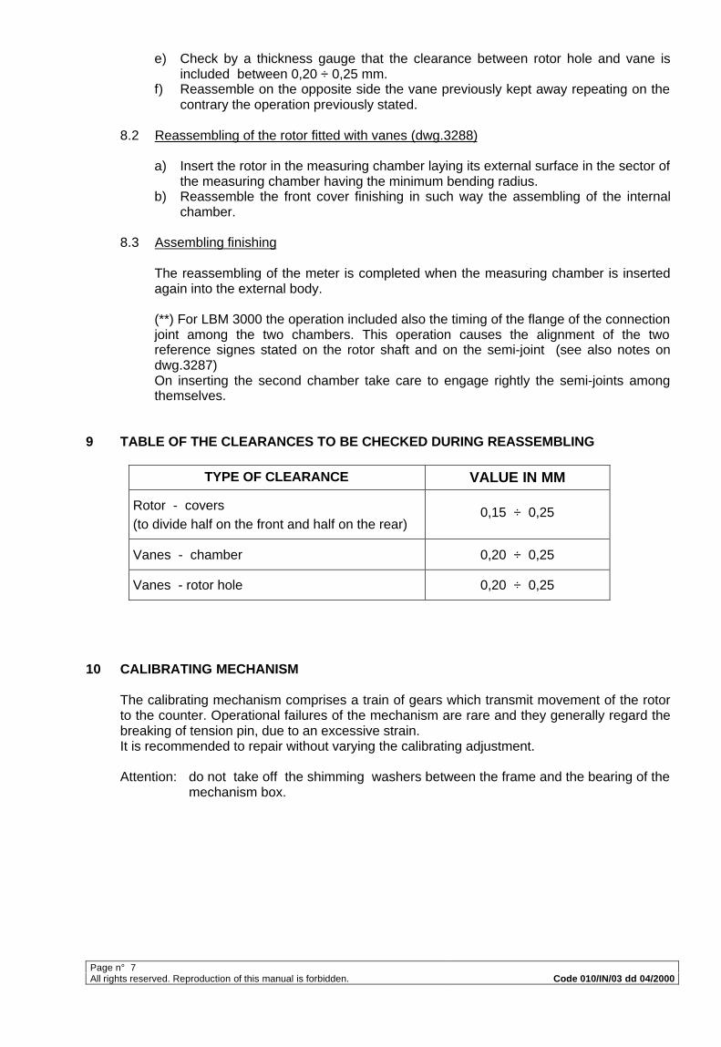
9 TABLE OF THE CLEARANCES TO BE CHECKED DURING REASSEMBLING
TYPE OF CLEARANCE VALUE IN MM
Rotor - covers(to divide half on the front and half on the rear)
0,15 ÷ 0,25
Vanes - chamber 0,20 ÷ 0,25
Vanes - rotor hole 0,20 ÷ 0,25
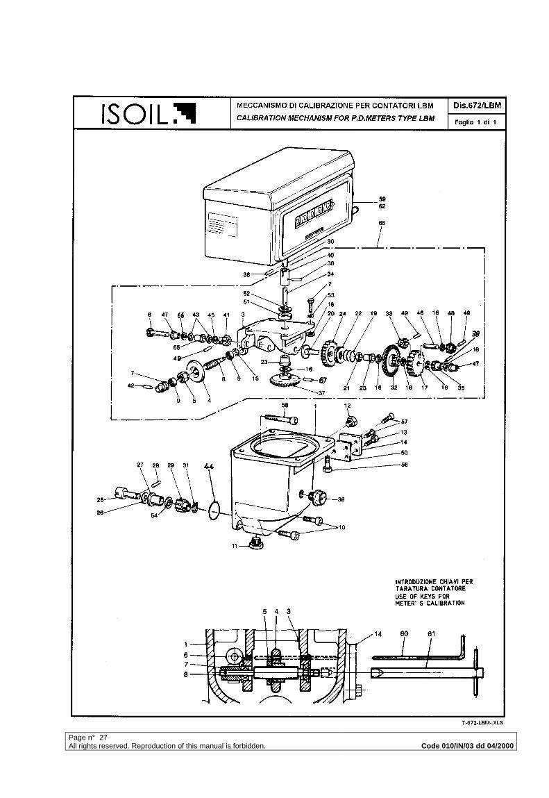
10 CALIBRATING MECHANISM
The calibrating mechanism comprises a train of gears which transmit movement of the rotorto the counter. Operational failures of the mechanism are rare and they generally regard thebreaking of tension pin, due to an excessive strain.It is recommended to repair without varying the calibrating adjustment.
Attention: do not take off the shimming washers between the frame and the bearing of themechanism box.
Page n° 8All rights reserved. Reproduction of this manual is forbidden. Code 010/IN/03 dd 04/2000
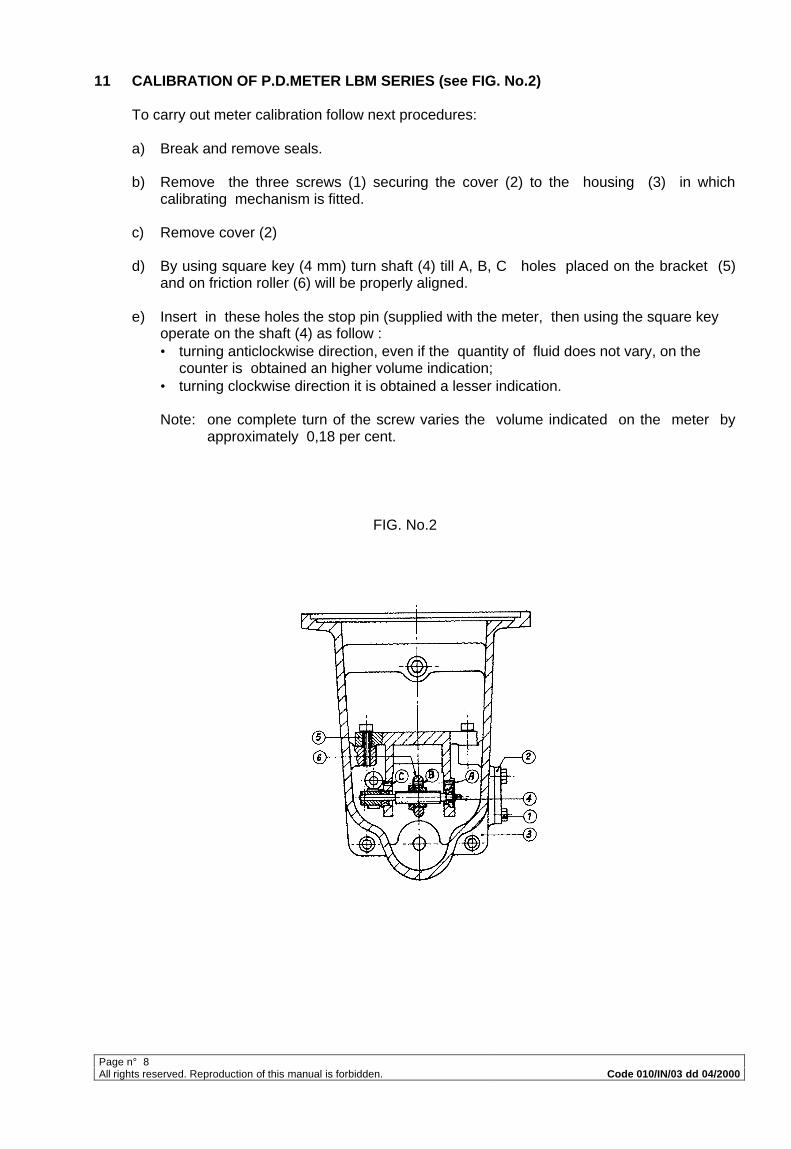
11 CALIBRATION OF P.D.METER LBM SERIES (see FIG. No.2)
To carry out meter calibration follow next procedures:
a) Break and remove seals.
b) Remove the three screws (1) securing the cover (2) to the housing (3) in whichcalibrating mechanism is fitted.
c) Remove cover (2)
d) By using square key (4 mm) turn shaft (4) till A, B, C holes placed on the bracket (5)and on friction roller (6) will be properly aligned.
e) Insert in these holes the stop pin (supplied with the meter, then using the square keyoperate on the shaft (4) as follow :• turning anticlockwise direction, even if the quantity of fluid does not vary, on the
counter is obtained an higher volume indication;• turning clockwise direction it is obtained a lesser indication.
Note: one complete turn of the screw varies the volume indicated on the meter byapproximately 0,18 per cent.
FIG. No.2
Page n° 9All rights reserved. Reproduction of this manual is forbidden. Code 010/IN/03 dd 04/2000
12 TESTS AFTER OVERHAUL
After overhaul, meter must be tested by a suitable proving system.As per Italian Weight and Measure Office rules the value stated by the counter of thep.d.meter compared with the volume stated by the level of the measuring chamber, must becontained between +0,3% and –0,2%.
EXAMPLE COUNTER READING PROVING TANK READING1000 1003 (+ 0,3%)1000 998 (- 0,2%)
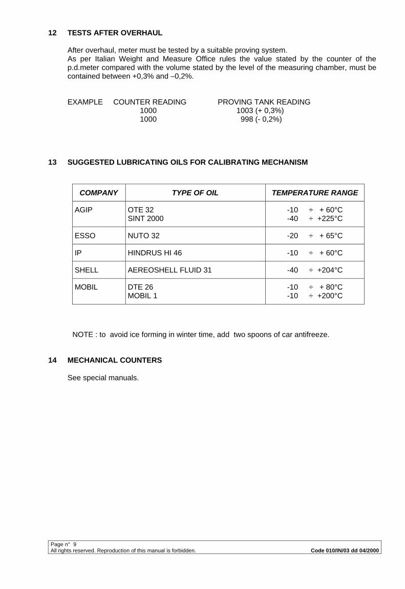
13 SUGGESTED LUBRICATING OILS FOR CALIBRATING MECHANISM
COMPANY TYPE OF OIL TEMPERATURE RANGE
AGIP OTE 32SINT 2000
-10 ÷ + 60°C-40 ÷ +225°C
ESSO NUTO 32 -20 ÷ + 65°C
IP HINDRUS HI 46 -10 ÷ + 60°C
SHELL AEREOSHELL FLUID 31 -40 ÷ +204°C
MOBIL DTE 26MOBIL 1
-10 ÷ + 80°C-10 ÷ +200°C
NOTE : to avoid ice forming in winter time, add two spoons of car antifreeze.
14 MECHANICAL COUNTERS
See special manuals.
Page n° 10All rights reserved. Reproduction of this manual is forbidden. Code 010/IN/03 dd 04/2000
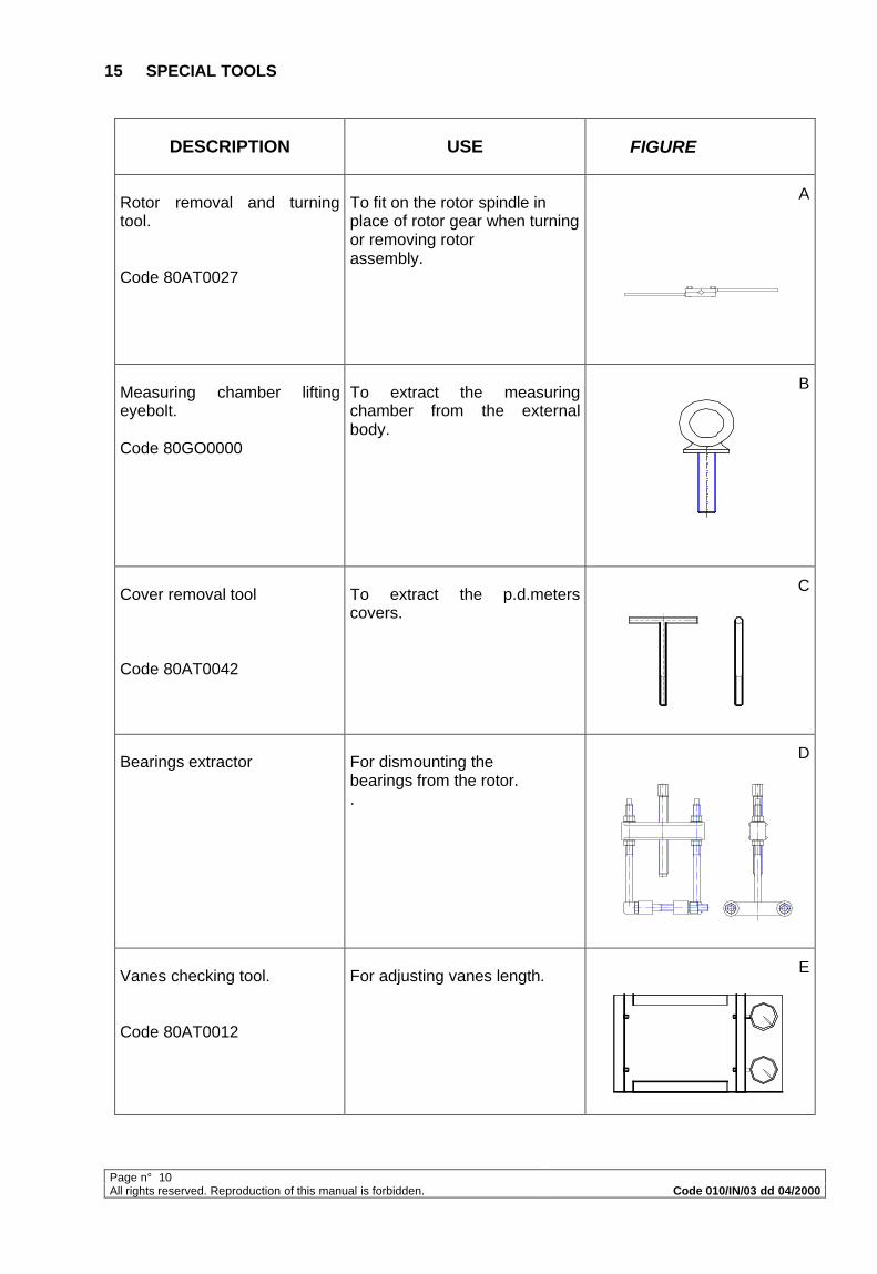
15 SPECIAL TOOLS
DESCRIPTION USE FIGURE
Rotor removal and turningtool.
Code 80AT0027
To fit on the rotor spindle inplace of rotor gear when turningor removing rotorassembly.
A
Measuring chamber liftingeyebolt.
Code 80GO0000
To extract the measuringchamber from the externalbody.
B
Cover removal tool
Code 80AT0042
To extract the p.d.meterscovers.
C
Bearings extractor For dismounting thebearings from the rotor..
D
Vanes checking tool.
Code 80AT0012
For adjusting vanes length. E
Page n° 11All rights reserved. Reproduction of this manual is forbidden. Code 010/IN/03 dd 04/2000
Page n° 12All rights reserved. Reproduction of this manual is forbidden. Code 010/IN/03 dd 04/2000
Page n° 13
All rights reserved. R
eproduction of this manual is forbidden.
Co
de 010/IN
/03 dd
04/2000
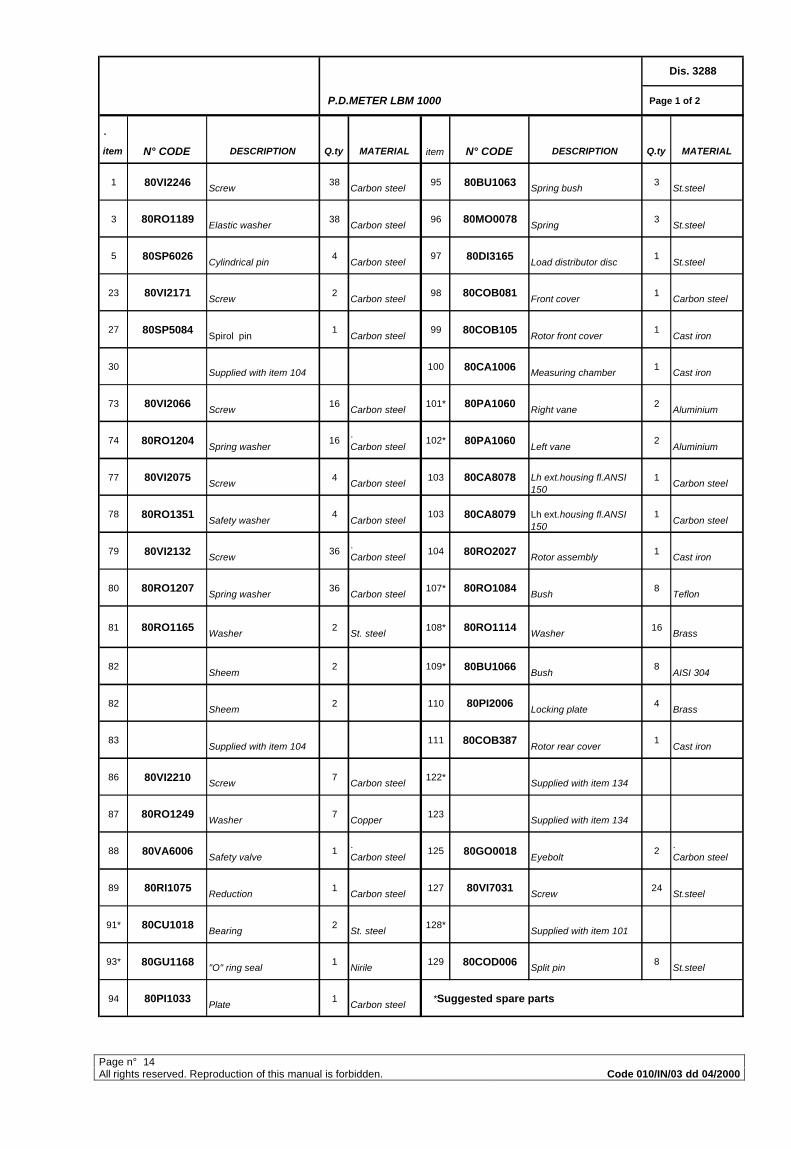
Page n° 14All rights reserved. Reproduction of this manual is forbidden. Code 010/IN/03 dd 04/2000
P.D.METER LBM 1000 Page 1 of 2
.
item N° CODE DESCRIPTION Q.ty MATERIAL item N° CODE DESCRIPTION Q.ty MATERIAL
1 80VI2246 Screw
38 Carbon steel
95 80BU1063 Spring bush
3 St.steel
3 80RO1189 Elastic washer
38 Carbon steel
96 80MO0078 Spring
3 St.steel
5 80SP6026 Cylindrical pin
4 Carbon steel
97 80DI3165 Load distributor disc
1 St.steel
23 80VI2171 Screw
2 Carbon steel
98 80COB081 Front cover
1 Carbon steel
27 80SP5084 Spirol pin
1 Carbon steel
99 80COB105 Rotor front cover
1 Cast iron
30 Supplied with item 104
100 80CA1006 Measuring chamber
1 Cast iron
73 80VI2066 Screw
16 Carbon steel
101* 80PA1060 Right vane
2 Aluminium
74 80RO1204 Spring washer
16. Carbon steel
102* 80PA1060 Left vane
2 Aluminium
77 80VI2075 Screw
4 Carbon steel
103 80CA8078 Lh ext.housing fl.ANSI 150
1 Carbon steel
78 80RO1351 Safety washer
4 Carbon steel
103 80CA8079 Lh ext.housing fl.ANSI 150
1 Carbon steel
79 80VI2132 Screw
36. Carbon steel
104 80RO2027 Rotor assembly
1 Cast iron
80 80RO1207 Spring washer
36 Carbon steel
107* 80RO1084 Bush
8 Teflon
81 80RO1165 Washer
2 St. steel
108* 80RO1114 Washer
16 Brass
82 Sheem
2 109* 80BU1066 Bush
8 AISI 304
82 Sheem
2 110 80PI2006 Locking plate
4 Brass
83 Supplied with item 104
111 80COB387 Rotor rear cover
1 Cast iron
86 80VI2210 Screw
7 Carbon steel
122* Supplied with item 134
87 80RO1249 Washer
7 Copper
123 Supplied with item 134
88 80VA6006 Safety valve
1. Carbon steel
125 80GO0018 Eyebolt
2. Carbon steel
89 80RI1075 Reduction
1 Carbon steel
127 80VI7031 Screw
24 St.steel
91* 80CU1018 Bearing
2 St. steel
128* Supplied with item 101
93* 80GU1168 "O" ring seal
1 Nirile
129 80COD006 Split pin
8 St.steel
94 80PI1033 Plate
1 Carbon steel
*Suggested spare parts
Dis. 3288
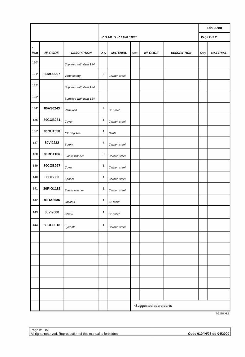
Page n° 15All rights reserved. Reproduction of this manual is forbidden. Code 010/IN/03 dd 04/2000
P.D.METER LBM 1000 Page 2 of 2
.
item N° CODE DESCRIPTION Q.ty MATERIAL item N° CODE DESCRIPTION Q.ty MATERIAL
130* Supplied with item 134
131* 80MO0207 Vane spring
8 Carbon steel
132* Supplied with item 134
133* Supplied with item 134
134* 80AS0243 Vane rod
4 St. steel
135 80COB231 Cover
1 Carbon steel
136* 80GU1558 "O" ring seal
1 Nitrile
137 80VI2222 Screw
8 Carbon steel
138 80RO1186 Elastic washer
8 Carbon steel
139 80COB027 Cover
1 Carbon steel
140 80DI6033 Spacer
1 Carbon steel
141 80RIO1183 Elastic washer
1 Carbon steel
142 80DA3036 Locknut
1 St. steel
143 80VI2000 Screw
1 St. steel
144 80GO0018 Eyebolt
1 Carbon steel
*Suggested spare parts
T-3288.XLS
Dis. 3288

Page n° 16
All rights reserved. R
eproduction of this manual is forbidden.
Co
de 010/IN
/03 dd
04/2000
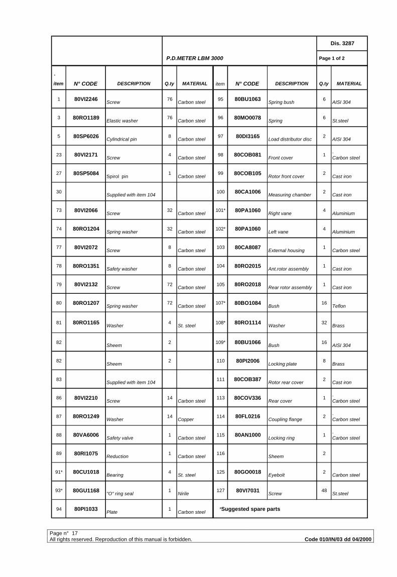
Page n° 17All rights reserved. Reproduction of this manual is forbidden. Code 010/IN/03 dd 04/2000
P.D.METER LBM 3000 Page 1 of 2
.
item N° CODE DESCRIPTION Q.ty MATERIAL item N° CODE DESCRIPTION Q.ty MATERIAL
1 80VI2246 Screw
76 Carbon steel
95 80BU1063 Spring bush
6 AISI 304
3 80RO1189 Elastic washer
76 Carbon steel
96 80MO0078 Spring
6 St.steel
5 80SP6026 Cylindrical pin
8 Carbon steel
97 80DI3165 Load distributor disc
2 AISI 304
23 80VI2171 Screw
4 Carbon steel
98 80COB081 Front cover
1. Carbon steel
27 80SP5084 Spirol pin
1 Carbon steel
99 80COB105 Rotor front cover
2 Cast iron
30 Supplied with item 104
100 80CA1006 Measuring chamber
2 Cast iron
73 80VI2066 Screw
32 Carbon steel
101* 80PA1060 Right vane
4 Aluminium
74 80RO1204 Spring washer
32 Carbon steel
102* 80PA1060 Left vane
4 Aluminium
77 80VI2072 Screw
8 Carbon steel
103 80CA8087 External housing
1 Carbon steel
78 80RO1351 Safety washer
8 Carbon steel
104 80RO2015 Ant.rotor assembly
1 Cast iron
79 80VI2132 Screw
72 Carbon steel
105 80RO2018 Rear rotor assembly
1 Cast iron
80 80RO1207 Spring washer
72 Carbon steel
107* 80BO1084 Bush
16 Teflon
81 80RO1165 Washer
4 St. steel
108* 80RO1114 Washer
32 Brass
82 Sheem
2 109* 80BU1066 Bush
16 AISI 304
82 Sheem
2 110 80PI2006 Locking plate
8 Brass
83 Supplied with item 104
111 80COB387 Rotor rear cover
2 Cast iron
86 80VI2210 Screw
14 Carbon steel
113 80COV336 Rear cover
1. Carbon steel
87 80RO1249 Washer
14 Copper
114 80FL0216 Coupling flange
2. Carbon steel
88 80VA6006 Safety valve
1 Carbon steel
115 80AN1000 Locking ring
1. Carbon steel
89 80RI1075 Reduction
1 Carbon steel
116 Sheem
2
91* 80CU1018 Bearing
4 St. steel
125 80GO0018 Eyebolt
2 Carbon steel
93* 80GU1168 "O" ring seal
1 Nirile
127 80VI7031 Screw
48 St.steel
94 80PI1033 Plate
1 Carbon steel
*Suggested spare parts
Dis. 3287
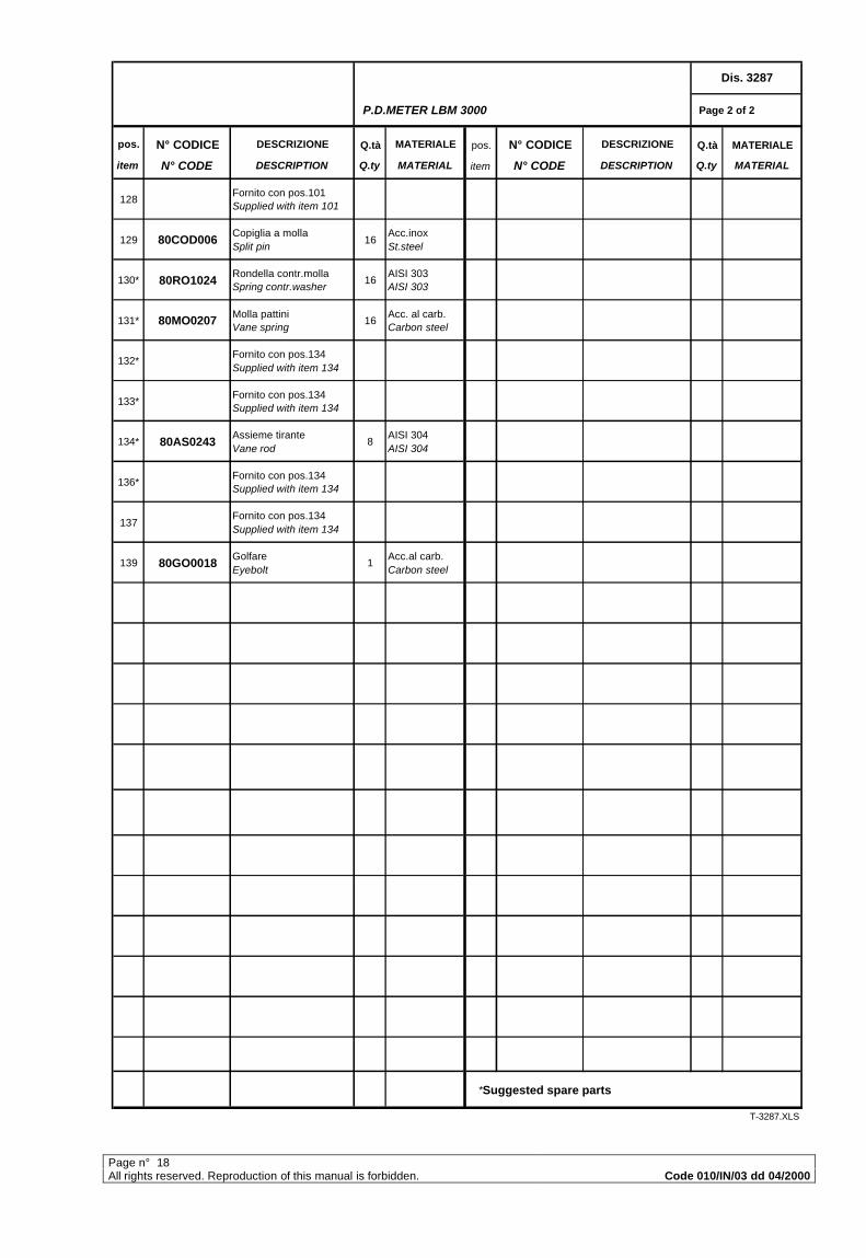
Page n° 18All rights reserved. Reproduction of this manual is forbidden. Code 010/IN/03 dd 04/2000
P.D.METER LBM 3000 Page 2 of 2
pos. N° CODICE DESCRIZIONE Q.tà MATERIALE pos. N° CODICE DESCRIZIONE Q.tà MATERIALE
item N° CODE DESCRIPTION Q.ty MATERIAL item N° CODE DESCRIPTION Q.ty MATERIAL
128Fornito con pos.101 Supplied with item 101
129 80COD006Copiglia a molla Split pin
16Acc.inox St.steel
130* 80RO1024Rondella contr.molla Spring contr.washer
16AISI 303 AISI 303
131* 80MO0207 Molla pattini Vane spring
16Acc. al carb. Carbon steel
132*Fornito con pos.134 Supplied with item 134
133*Fornito con pos.134 Supplied with item 134
134* 80AS0243Assieme tirante Vane rod
8AISI 304 AISI 304
136*Fornito con pos.134 Supplied with item 134
137Fornito con pos.134 Supplied with item 134
139 80GO0018Golfare Eyebolt
1Acc.al carb. Carbon steel
*Suggested spare parts
T-3287.XLS
Dis. 3287
Page n° 19All rights reserved. Reproduction of this manual is forbidden. Code 010/IN/03 dd 04/2000
….
.
Page n° 20All rights reserved. Reproduction of this manual is forbidden. Code 010/IN/03 dd 04/2000
Page 1 of 1
.
item N° CODE DESCRIPTION Q.ty MATERIAL item N° CODE DESCRIPTION Q.ty MATERIAL
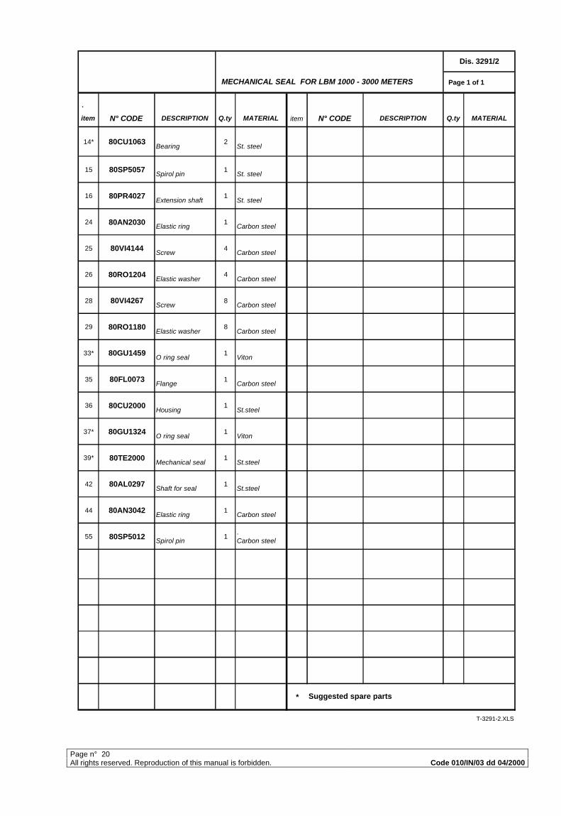
14* 80CU1063 Bearing
2 St. steel
15 80SP5057 Spirol pin
1 St. steel
16 80PR4027 Extension shaft
1 St. steel
24 80AN2030 Elastic ring
1 Carbon steel
25 80VI4144 Screw
4 Carbon steel
26 80RO1204 Elastic washer
4 Carbon steel
28 80VI4267 Screw
8 Carbon steel
29 80RO1180 Elastic washer
8 Carbon steel
33* 80GU1459 O ring seal
1 Viton
35 80FL0073 Flange
1 Carbon steel
36 80CU2000 Housing
1 St.steel
37* 80GU1324 O ring seal
1 Viton
39* 80TE2000 Mechanical seal
1 St.steel
42 80AL0297 Shaft for seal
1 St.steel
44 80AN3042 Elastic ring
1 Carbon steel
55 80SP5012 Spirol pin
1. Carbon steel
*
T-3291-2.XLS
Suggested spare parts
Dis. 3291/2
MECHANICAL SEAL FOR LBM 1000 - 3000 METERS
Page n° 21All rights reserved. Reproduction of this manual is forbidden. Code 010/IN/03 dd 04/2000
Page n° 22All rights reserved. Reproduction of this manual is forbidden. Code 010/IN/03 dd 04/2000
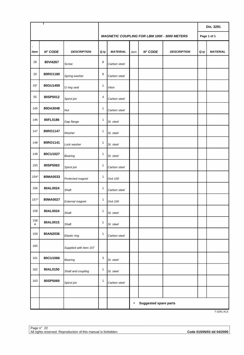
MAGNETIC COUPLING FOR LBM 1000 - 3000 METERS Page 1 of 1
.
item N° CODE DESCRIPTION Q.ty MATERIAL item N° CODE DESCRIPTION Q.ty MATERIAL
28 80VI4267 Screw
8 Carbon steel
29 80RO1180 Spring washer
8 Carbon steel
33* 80GU1459 O ring seal
1 Viton
55 80SP5012 Spirol pin
4. Carbon steel
145 80DA3048 Nut
1 Carbon steel
146 80FL0186 Gap flange
1 St. steel
147 80RO1147 Washer
1 St. steel
148 80RO1141 Lock washer
1 St. steel
149 80CU1027 Bearing
1 St. steel
150 80SP5063 Spirol pin
1 Carbon steel
154* 80MA0033 Protected magnet
1 Oxit 100
156 80AL0024 Shaft
1 Carbon steel
157* 80MA0027 External magnet
1 Oxit 100
158 80AL0024 Shaft
1 St. steel
158 A
80AL0015 Shaft
1 St. steel
159 80AN2036 Elastic ring
1 Carbon steel
160 Supplied with item 157
161 80CU1066 Bearing
3 St. steel
162 80AL0150 Shaft and coupling
1 St. steel
163 80SP5069 Spirol pin
1 Carbon steel
*
T-3291.XLS
Dis. 3291
Suggested spare parts
I
Page n° 23All rights reserved. Reproduction of this manual is forbidden. Code 010/IN/03 dd 04/2000
Page n° 24All rights reserved. Reproduction of this manual is forbidden. Code 010/IN/03 dd 04/2000
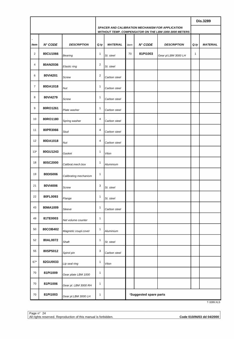
SPACER AND CALIBRATION MECHANISM FOR APPLICATION
WITHOUT TEMP. COMPENSATOR ON THE LBM 1000-3000 METERS
.
item N° CODE DESCRIPTION Q.ty MATERIAL item N° CODE DESCRIPTION Q.ty MATERIAL
2 80CU1066 Bearing
1 St. steel
70 81PI1003 Gear pl.LBM 3000 LH
1
4 80AN2036 Elastic ring
2 St. steel
6 80VI4201 Screw
2 Carbon steel
7 80DA1018 Nut
1 Carbon steel
8 80VI4279 Screw
1 Carbon steel
9 80RO1261 Plate washer
1 Carbon steel
10 80RO1180 Spring washer
4. Carbon steel
11 80PR3066 Stud
4 Carbon steel
12 80DA1018 Nut
4. Carbon steel
13* 80GU1243 Gasket
1 Viton
18 80SC2000 Calibrat.mech.box
1 Aluminium
19 80DI5006 Calibrating mechanism
1
21 80VI4006 Screw
3 St. steel
22 80FL0093 Flange
1 St. steel
43 80MA1009 Sleeve
1 Carbon steel
49 81TE0003 Net volume counter
1
50 80COB402. Magnetic coupl.cover
1 Aluminium
52 80AL0072 Shaft
1 St. steel
55 80SP5012 Spirol pin
3 Carbon steel
67* 82GU0033 Lip seal ring
1 Viton
70 81PI1009 Gear plate LBM 1000
1
70 81PI1006 Gear pl. LBM 3000 RH
1
70 81PI1003 Gear pl.LBM 3000 LH
1 *Suggested spare parts
T-3289.XLS
Dis.3289
Page n° 25
All rights reserved. R
eproduction of this manual is forbidden.
Co
de 010/IN
/03 dd
04/2000
Page n° 26All rights reserved. Reproduction of this manual is forbidden. Code 010/IN/03 dd 04/2000
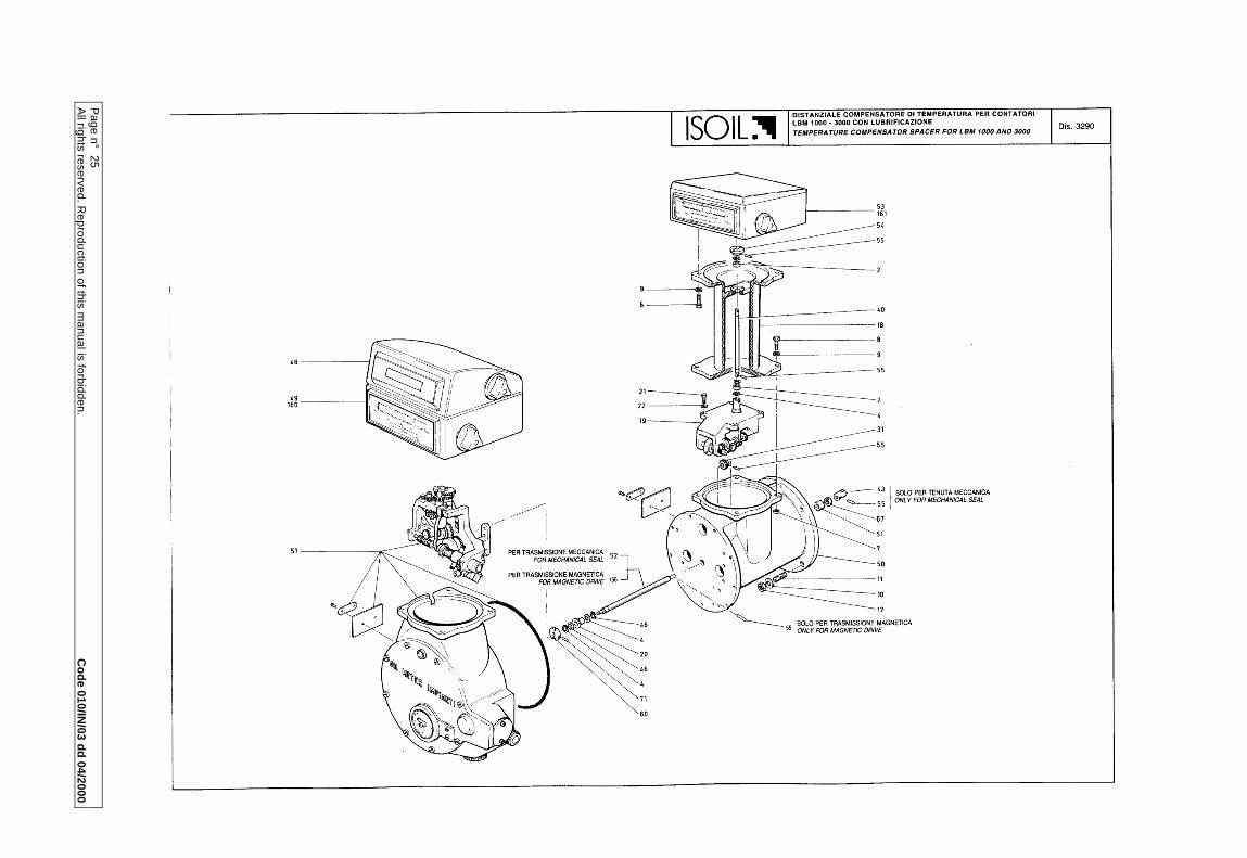
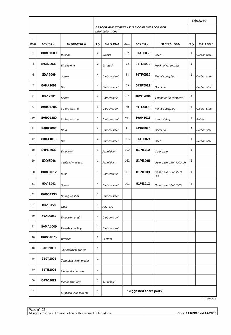
SPACER AND TEMPERATURE COMPENSATOR FOR
LBM 1000 - 3000
.
item N° CODE DESCRIPTION Q.ty MATERIAL item N° CODE DESCRIPTION Q.ty MATERIAL
2 80BO1009 Bushes
2 Bronze
52 80AL0069 Shaft
1 Carbon steel
4 80AN2036 Elastic ring
2 St. steel
53 81TE1003 Mechanical counter
1
6 80VI9009 Screw
4 Carbon steel
54 80TR0012 Female coupling
1 Carbon steel
7 80DA1099 Nut
4 Carbon steel
55 80SP5012 Spirol pin
4 Carbon steel
8 80VI2081 Screw
4 Carbon steel
57 80CO2009 Temperature compens.
1
9 80RO1204 Spring washer
4 Carbon steel
60 80TR0009 Female coupling
1 Carbon steel
10 80RO1180 Spring washer
4 Carbon steel
67* 80AN1015 Lip seal ring
1 Rubber
11 80PR3066 Stud
4 Carbon steel
71 80SP5024 Spirol pin
1 Carbon steel
12 80DA1018 Nut
4. Carbon steel
156 80AL0024 Shaft
1 Carbon steel
18 80PR4036 Extension
1 Aluminium
160 81PI1012 Gear plate
1
19 80DI5006 Calibration mech.
1 Aluminium
161 81PI1006 Gear plate LBM 3000 LH
1
20 80BO1012 Bush
1 Carbon steel
161 81PI1003 Gear plate LBM 3000 RH
1
21 80VI2042 Screw
4. Carbon steel
161 81PI1012 Gear plate LBM 1000
1
22 80RO1198 Spring washer
1 Carbon steel
31 80VI3153 Gear
1 AISI 420
40 80AL0030 Extension shaft
1 Carbon steel
43 80MA1009 Female coupling
1 Carbon steel
46 80RO1075 Washer
2 St.steel
48 81ST1000 Accum.ticket printer
1
48 81ST1003 Zero start ticket printer
1
49 81TE1003 Mechanical counter
1
50 80SC2021 Mechanism box
1 Aluminium
51 Supplied with item 50
1 *Suggested spare parts
T-3290.XLS
Dis.3290
Page n° 27All rights reserved. Reproduction of this manual is forbidden. Code 010/IN/03 dd 04/2000

Page n° 28All rights reserved. Reproduction of this manual is forbidden. Code 010/IN/03 dd 04/2000
CALIBRATION MECHANISM FOR LBM 1000-3000 Page 1 of 2
.
item N° CODE DESCRIPTION Q.ty MATERIAL item N° CODE DESCRIPTION Q.ty MATERIAL
1 80SC2000 Calibr.mechanism box
1 Aluminium
25 80AL0282 Drive shaft
1 Aisi 420
2 80VI2042 Support screw
4 Carbon steel
26 80RO1066 Washer
2 Carbon steel
3 80SU0012 Calibr.mech.support
1 Aluminium
27 80BO1009 Bush
1 Bronze
4 80AS0027 Friction wheel
1 Carbon steel
28* 80SP5009 Spirol pin
1 Carbon steel
5 Supplied with item 4
29 80IN3150 Z = 20 gear
1 St.steel
6* 80AS0129 Shaft with pinion
1. Carbon steel
30 80AL0270 Extension shaft
1 Carbon steel
7 80AS0258 Worm screw
1 Carbon steel
31 80AN2000 Circlip for shaft
1. Carbon steel
8* Supplied with item 7
32 80PI5000 Bevel pinion
1. Carbon steel
9* 80CU1081 Bearing
2 St.steel
33 Supplied with item 17
10 80VI4201 Screw
2 Carbon steel
34 80AS0084 Shaft/gear assy
1 Aisi 420
11 80TA1072 Oil discharge plug
1 35 80IN3165 Gear
1. Carbon steel
12 80TA1015 Oil charge plug
1 37 Supplied with item 34
13 80VI5117 Screw
1 Carbon steel
38 80SP5009 Spirol pin
3. Carbon steel
14 80COB069 Calibrating cap
1 Aluminium
39 81IN0006 Oil level indicator
1
15 80AN2018 Bearing circlip stop
1 Carbon steel
40 80MA1009 . Transmission sleeve
1 Carbon steel
16 80RO1063 Washer
7 Carbon steel
41 Supplied with item 6
17 80AS0069 Pinion assy
1 Carbon steel
42 80SP5000 Spirol pin
2 Carbon steel
19 80MO0228 Friction plate spring
1 Stainless steel
43 80RO1078 Wahser
2. Carbon steel
20 80PI1057 Friction plate
1 Carbon steel
44* 80GU1243 Gasket
1 Viton
21 80RO1042 Washer
1 Carbon steel
45 80AN2006 Circlip
1 Carbon steel
22* 80CU1045 Axial bearing
1 Carbon steel
46 Supplied with item 17
23 80BO1000 Bush
2 Bronze
47 80BO1000 Bush
2 Bronze
24 80IN3234 Gear Z=66
1. Carbon steel *Suggested spare parts
Dis. 672/LBM
Page n° 29All rights reserved. Reproduction of this manual is forbidden. Code 010/IN/03 dd 04/2000
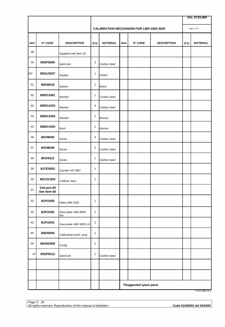
CALIBRATION MECHANISM FOR LBM 1000-3000 Page 2 of 2
.
item N° CODE DESCRIPTION Q.ty MATERIAL item N° CODE DESCRIPTION Q.ty MATERIAL
48 Supplied with item 18
49 80SP5006 Spirol pin
3 Carbon steel
50* 80GU0207 Gasket
1 Rubber
51 80DI6018 Spacer
1 Brass
52 80RO1081 Washer
1 Carbon steel
53 80RO1033 Washer
4 Carbon steel
54 80RO1093 Washer
1 Bronze
55 80BO1000 Bush
1 Bronze
56 80VI9009 Screw
4 Carbon steel
57 80VI8048 Screw
2 Carbon steel
58 80VI4312 Screw
1 Carbon steel
59 81TE0003 Counter VR 7887
1
60 80COC003 Calibrat. keys
1
61Ved.pos.60 See item 60
62 81PI1009 Plate LBM 1000
1
62 81PI1006 Gear plate LBM 3000 RH
1
62 81PI1003 Gear plate LBM 3000 LH
2
65 80DI5006 Calibrating mech. assy
1
66 80AN2009 Circlip
1
67 80SP5012 Spirol pin
1 Carbon steel
*Suggested spare parts
T-672-LBM.XLS
Dis. 672/LBM
Page n° 30All rights reserved. Reproduction of this manual is forbidden. Code 010/IN/03 dd 04/2000
Page n° 31All rights reserved. Reproduction of this manual is forbidden. Code 010/IN/03 dd 04/2000
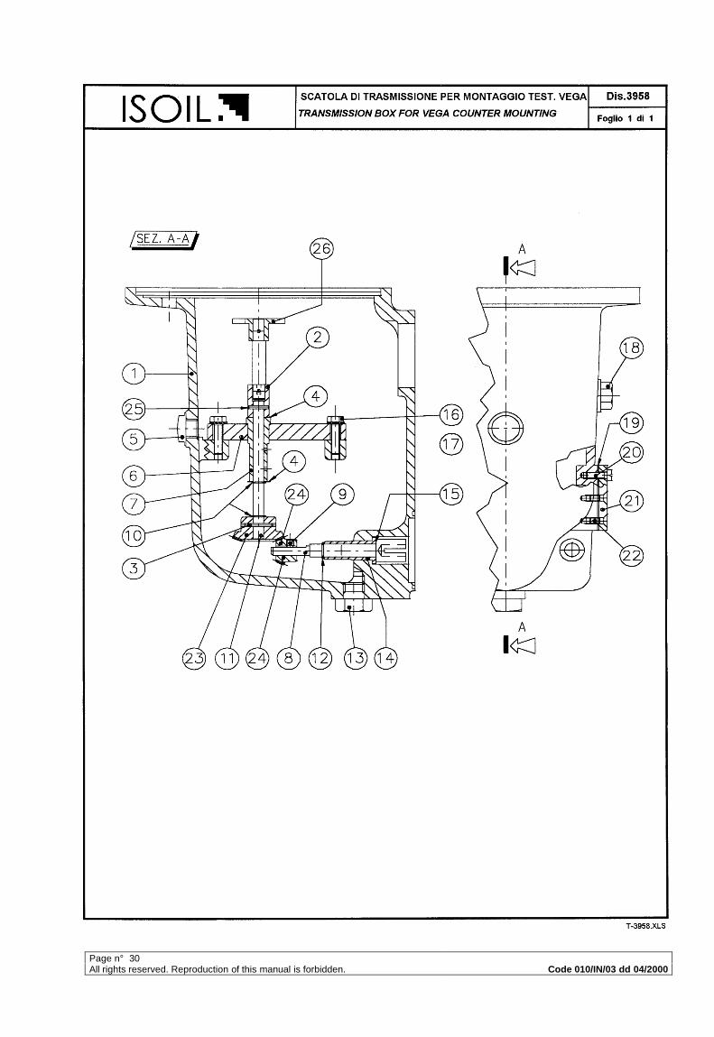
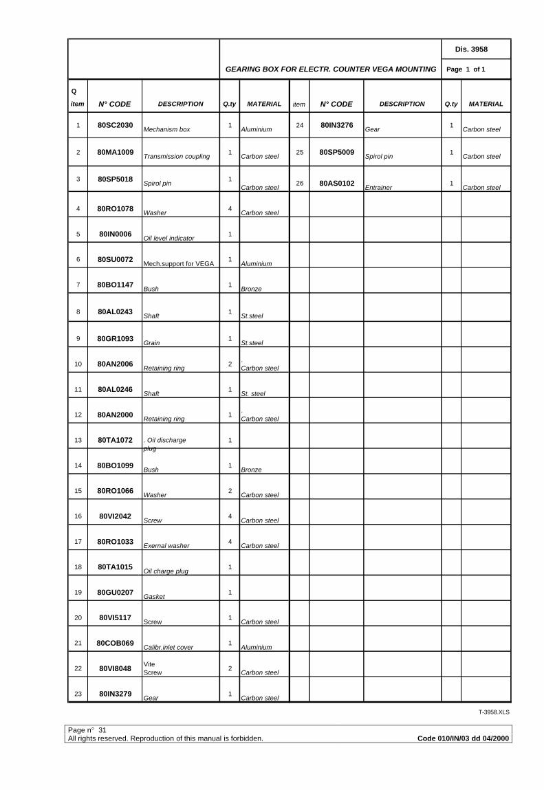
Dis. 3958
GEARING BOX FOR ELECTR. COUNTER VEGA MOUNTING Page 1 of 1
Q
item N° CODE DESCRIPTION Q.ty MATERIAL item N° CODE DESCRIPTION Q.ty MATERIAL
1 80SC2030 Mechanism box
1 Aluminium
24 80IN3276 Gear
1 Carbon steel
2 80MA1009 Transmission coupling
1 Carbon steel
25 80SP5009 Spirol pin
1 Carbon steel
3 80SP5018 Spirol pin
1Carbon steel
26 80AS0102 Entrainer
1 Carbon steel
4 80RO1078 Washer
4 Carbon steel
5 80IN0006 Oil level indicator
1
6 80SU0072 Mech.support for VEGA
1 Aluminium
7 80BO1147 Bush
1 Bronze
8 80AL0243 Shaft
1 St.steel
9 80GR1093 Grain
1 St.steel
10 80AN2006 Retaining ring
2. Carbon steel
11 80AL0246 Shaft
1 St. steel
12 80AN2000 Retaining ring
1. Carbon steel
13 80TA1072 . Oil discharge plug
1
14 80BO1099 Bush
1 Bronze
15 80RO1066 Washer
2 Carbon steel
16 80VI2042 Screw
4 Carbon steel
17 80RO1033 Exernal washer
4 Carbon steel
18 80TA1015 Oil charge plug
1
19 80GU0207 Gasket
1
20 80VI5117 Screw
1 Carbon steel
21 80COB069 Calibr.inlet cover
1 Aluminium
22 80VI8048Vite Screw
2 Carbon steel
23 80IN3279 Gear
1 Carbon steel
T-3958.XLS