Embed Size (px)
Citation preview

User ManualManuel de l’utilisateurBedienhandbuchManual del Usario
• PL218A• PL224A• PL230A• PL236A
PL2A Audio Power Amplifierswith Analog Signal Processing
POWERLIGHT 2A
TD-000089-00Rev.B
*TD-000089-00*

EXPLANATION OF GRAPHICAL SYMBOLS
The lightning flash with arrowhead symbol within an equilateral triangle is intended to alert the user to the presence of uninsulated “dangerous” voltage within theproduct’s enclosure that may be of sufficient magnitude to constitute a risk of electric shock to humans.
The exclamation point within an equilateral triangle is intended to alert the user to the presence of important operating and maintenance (servicing) instructions in theliterature accompanying the product.
CAUTION: To reduce the risk of electric shock, do not remove the cover. No user-serviceable parts inside.Refer servicing to qualified personnel.WARNING: To prevent fire or electric shock, do not expose this equipment to rain or moisture.
FCC INTERFERENCE STATEMENTNOTE: This equipment has been tested and found to comply with the limits for a class B digital device, pursuant to part 15 of the FCC rules. These limits are designed to providereasonable protection against harmful interference in a residential installation. This equipment generates, uses, and can radiate radio frequency energy and if not installed and used inaccordance to the instructions , may cause harmful interference to radio communications. However, there is no guarantee that interference will not occur in a particular installation. Ifthis equipment does cause harmful interference to radio or television reception, which can be determined by switching the equipment off & on, the user is encouraged to try to correctthe interference by one or more of the following measures:
- Reorient or relocate the receiving antenna.- Increase the separation between the equipment and the receiver.- Connect the equipment into an outlet on a circuit different from that to which the receiver is connected.- Consult the dealer or an experienced radio or TV technician for help.
CAUTION
RISK OF ELECTRIC SHOCKDO NOT OPEN
© Copyright 2000, 2007 QSC Audio Products, Inc.QSC® is a registered trademark of QSC Audio Products, Inc.
PowerLight™ is a trademark of QSC Audio Products, Inc.“QSC” and the QSC logo are registered with the U.S. Patent and Trademark Office
All trademarks are the property of their respective owners.
2

TABLE OF CONTENTSExplanation of Graphical Symbols.......................................................2
FCC Interference Statement....................................................................2
INTRODUCTION:PL2A Series Overview.................................................4Front Panel...................................................................4Rear Panel....................................................................5Side Panel....................................................................5
FEATURES & SETUP:
Rear Panel Switches-INPUT CONFIGURATION..............................................6MODE...........................................................................7DATAPORT INPUT SIGNAL..........................................8GAIN-SENSITIVITY SELECT.........................................9
Side Panel Switches and SIP networks-Subaudio Filter & Subaudio Frequency....................10Lo Frequency Delay and HF ATTEN..................................11HORN BOOST.............................................................12POWER LIMITER........................................................13CLIP LIMITER..............................................................15Crossover & Delay SIP Networks.............................16
DataPort, Front Panel LEDs, Gain Controls-Basic Overview...........................................................18
INSTALLATION:Rack mounting & Mounting Dimensions.................19Fan Cooling & AC Mains..........................................20
CONNECTIONS:Inputs................................................................................21Outputs............................................................................22
SECURITY PANEL USE & INSTALLATION...................................................24
OPERATION:Gain Controls................................................................25AC Power Switch...............................................................25Front Panel LED Indicators.................................................25Normal operating levels......................................................25
TROUBLESHOOTING.......................................................................................26
TECHNICAL OVERVIEW & BLOCK DIAGRAM............................................28
SPECIFICATIONS..............................................................................................30
WARRANTY INFORMATION..........................................................................32
HOW TO CONTACT QSC AUDIO PRODUCTS..............................................32
BLANK SETUP SHEETS...................................................................................33
3

FRONT PANEL
1. Power switch2. Cooling vents3. Gain control (1 per
channel)4. CLIP, -10 dB, -20 dB and
SIGNAL indicator LEDs, 1per channel
5. POWER, BRIDGE, andPARALLEL indicator LEDs
6. BI-AMP indicator LED 7. Handles
Thank you for the purchase of your new POWERLIGHT 2A amplifier. To get the mostout of your amplifier, review this manual carefully. The installation and operationsections provide proper connection and operation guidelines.
The POWERLIGHT 2A expands upon the features of the POWERLIGHT 2. Theflexibility, user-friendliness and reliability of this amplifier will make it a valuablepart of your system for years to come.
The POWERLIGHT 2A was designed to fit your system. You can adjust the inputsensitivity to match the output capability of your mixing board. DataPort inputsignals can be summed before or after internal processing so that conflicts withexternal processing are avoided. The 4th order Linkwitz-Riley crossover hasindependent adjustment of crossover frequency and defeatable low-pass delaytime. The high-pass side of the crossover includes separate binary adjustments fortrim and driver EQ. The precision limiters provide separate adjustment of limiterthreshold, peak mode and attack/release times. You can adjust the limiterthreshold between 100% and 3% of available power. The limiters have a gentlelimiting knee which preserves a sense of signal dynamics. In bi-amplified systems,a slower attack/release time can be used on the low frequency channel. Thelimiters can also be connected together to maintain stereo balance in full rangemode or frequency balance in bi-amplified mode. A peak limiting mode with a fastattack time provides protection for fragile high frequency drivers.
The POWERLIGHT 2A is easy to use. All operating mode switches are groupedtogether on the rear panel. These critical switches have color-coded LED’s topositively confirm switch position. A brilliant blue LED on the front clearlyindicates when the amplifier is in bi-amp mode. Limiter threshold, high-pass trim(HF ATTEN) and high-pass EQ (HORN BOOST) levels use combinations of twoposition switches for easy adjustment. These less used switches are located onthe side panel.
The POWERLIGHT 2A is built for the long haul. Rubber-isolated XLR inputconnectors reduce stress on the contact pins and provide a tight, noise-freeconnection. All signal processing is done in side loops and then returned to themain signal path. This maintains high signal fidelity and provides a more robustsystem in the unlikely event a processor ceases to function.
Your new POWERLIGHT 2A amplifier will give you many years of great sound. ThePOWERLIGHT 2A is the most flexible, durable and best performing amplifier youcan buy.
INTRODUCTION: PL2A OVERVIEW
4

REAR PANEL1. DataPort2. Terminal block inputs3. Configuration switches4. XLR inputs5. Speakon outputs6. Binding post outputs7. Cooling air inlet vents8. Serial number label9. IEC connector for AC power cord9a. Power cord retaining clip (install on item 8)
SIDE PANEL1. Low pass delay network SIP* socket (J5)2. Crossover frequency network SIP socket (J4)3. Subaudio filter push-button switches (1 per
channel)4. Subaudio filter “on” indicator LEDs (1 per channel)5. DIP** switch for subaudio filter frequency select,
low frequency delay enable, HF attenuation and horn boost
6. DIP switches for power limiting adjustments and clip limiting enable
7. Activity LEDs for indication of power limiter activity (1 per channel)
*SIP is the abbreviation for Single-In-line Package**DIP is the abbreviation for Dual-In-line Package
INTRODUCTION: PL2A OVERVIEW
5
Side cover plate removed for this illustration

INPUT CONFIGURATION- This switch selects between STEREO or PARALLELinput configuration. The indicator LED’s above the switch confirm the switch setting.
FEATURES & SETUP- REAR PANEL SWITCHES: INPUT CONFIGURATION
PARALLEL: The CH 1 and CH 2 inputs are connected together, applying asingle input signal to both channels of the amplifier. A signal into anyinput jack will drive both channels. Each channel's subaudio filtering, cliplimiting, and gain control still function independently. Each channel feedsits own speaker load.
You can patch the input signal on to additional amplifiers (“daisy-chain”)by using any of the remaining input jacks. This feature eliminates theneed for “Y” cables.
The orange PARALLEL LED on the front panel clearly indicates when theamplifier in configured for PARALLEL input.
When to use PARALLEL input configuration: Use PARALLEL whenyou need one signal to drive both channels.
STEREO: Each input is sent to its respective channel. Each channel hasindependent subaudio filtering, clip limiting, gain control, and outputs. InSTEREO mode, a full-frequency signal may be presented to each channel.
When to use STEREO input configuration: Use STEREO for stereosources (L-R inputs) and any other situation that requires each channel tobe completely separate from the other.
NOTE: The “normal” position of the MODEswitch is 2 CH when operating in STEREO orPARALLEL input for the operating conditionsshown above. See the following section formore information regarding the MODE switch.
NOTE: Ensure that the INPUT CONFIGURATIONswitch is set to STEREO when feeding twoseparate signals to the two channels.
6

FEATURES & SETUP- REAR PANEL SWITCHES: MODE
MODE- This switch selects between BI-AMP, 2 CH, or BRIDGE modes of operation.The indicator LED’s above the switch confirm the selection.
BRIDGE: This mode combines both output channels into one output. Thismode is for driving a single, high-powered load with twice the “normal”voltage swing. This results in about 4 times the peak power and aboutthree times the sustained power of a single channel. This mode uses theinput, gain control, subaudio filter, and clip limiter of CH 1; CH 2's filterand clip limiter have no effect. The yellow BRIDGE LED on the front panelindicates when the amp is in BRIDGE mode.
When to use BRIDGE mode: Use BRIDGE mode when you need todeliver the power of two channels to a single 8 or 4 ohm load, such as asubwoofer. Do not use less than 4 ohm loads in BRIDGE mode.
2 CH: This is the “normal” mode used for stereo and parallel inputconfiguration. Each channel carries full-frequency signals (no crossover)and is independently controlled (gain, processing, output connection).
BI-AMP: This puts the amplifier into a “crossover” mode. CH 1 receivesthe low frequencies and CH 2 is receives the high frequencies. Thecrossover is a 4th order Linkwitz-Riley. The crossover frequency and low-frequency alignment delay are “programmed” with SIP (single in-linepackage) resistor networks . These small plug-in networks are installedfrom the side of the amplifier and plug into J4 and J5. WARNING: Do notinsert or remove networks with the power turned on. See the SIP NetworkSelection and Installation section for more information. The HF ATTEN,HORN BOOST, and SUBAUDIO FILTER controls are active in BI-AMPmode. The blue BI-AMP LED on the front panel indicates when the ampis in bi-amp mode.
When to use BI-AMP mode: Use BI-AMP when you need to split thehigh frequency and low frequency signals to power separate driver types.
BRIDGE MODE OUTPUT CONNECTION-Note that speaker connection for bridge mono mode is different than other modes.See section on Connections: Outputs for proper bridge mode output connections.
7

DATAPORT INPUT SIGNAL- This switch selects the regular inputs or theDataPort inputs, and allows the DataPort to enter before or after the analogprocessing. WARNING: There is no DataPort “flag” for this setting, so the appropriatesetting must be confirmed manually.
FEATURES & SETUP- REAR PANEL SWITCHES: DATAPORT INPUT SIGNAL
OFF: If the DATAPORT CONNECTION is not being used, set to the OFF position. TheDataPort MONITOR SIGNALS and STANDBY are still active, but the DataPort input signalswill not reach the amplifier.
PRE PROC: This setting will insert the DATAPORT signals ahead of the amplifier’s signalprocessor. If you are using external processing on the DATAPORT input signal, be aware thatadditional internal processing will be added to the signal. This may cause unexpected overallresults.
POST PROC: This selection inserts the DATAPORT signals after the amplifier’s processor.The subaudio filters and clip limiting remain functional, but all other processing isbypassed. See the Block Diagram for more detailed signal flow information.
DATAPORT signal routing options using the DATAPORT INPUT SIGNAL switch
8

GAIN-SENSITIVITY SELECT- This switch selects the gain structure of the amplifier. Each channelruns through a gain buffer which allows all models to have either a uniform 1.2 Vrms input sensitivity ora uniform 26 or 32 dB of voltage gain (all measured with the GAIN controls at maximum). The internalsignal leaving this stage is approximately +4 dB, leaving about 16 dB of headroom for the rest of thesignal processing. NOTE: The GAIN-SENSITIVITY SELECT setting does not effect DataPort gain in anymode.
FEATURES & SETUP- REAR PANEL SWITCHES: GAIN-SENSITIVITY SELECT
1.2 Vrms: This selection sets the input sensitivity to approximately 1.2 Vrms.This is the input voltage required to drive the amplifier to rated output powerinto an 8 ohm load.
26 dB: This selection sets the maximum voltage gain of the amplifier toapproximately 26 dB.
32 dB: This selection sets the maximum voltage gain of the amplifier toapproximately 32 dB
9

The side panel cover plate must be removed to access the side panel switches.
CH1 SUBAUDIO FILTER, CH2 SUBAUDIO FILTER- These push-button switches are usedto turn on or off the SUBAUDIO FILTER for each channel. Press the switch in for ON; the greenLED illuminates when the filter is ON. Push in and allow the switch to release for OFF; the greenLED extinguishes when the filter is OFF.
The filter’s roll-off frequency is determined by each channel’s SUBAUDIO FREQUENCY switch.When the filter is switched OFF, a 5 hertz roll-off frequency protects the load against DC or deepsubaudio output from the amplifier. Unless you already have filtering upstream of the amplifier,use the SUBAUDIO FILTER to protect your speakers from cone over-excursion caused byfrequencies below the speaker’s limits. The OFF position should be used only for subwoofersystems with rated frequency response below 30 hertz or if low frequency filtering is provided byother devices.
CH1 SUBAUDIO FREQUENCY, CH2 SUBAUDIO FREQUENCY- These switchesdetermine the low frequency roll-off of the SUBAUDIO FILTER. Generally, match the frequencyselection to your speaker’s low frequency capability. This improves speaker performance bylimiting subaudio cone movement, making more power available for the speaker’s ratedfrequency range. 30 Hz and 50 Hz are the available settings. If the SUBAUDIO FILTER switchesare OFF, these settings will have no effect. These switches are located on sections 1 and 10 ofthe left-most DIP switch.
FEATURES & SETUP- SIDE PANEL SWITCHES: SUBAUDIO FILTER and SUBAUDIO FREQUENCY
Subaudio filter frequency response- filter off
Subaudio filter frequency response- filter on, 50 hertz selected Subaudio filter frequency response- filter on, 30 hertz selected10

FEATURES & SETUP- SIDE PANEL SWITCHES: LO FREQ DELAY and HF ATTEN
LO FREQ DELAY- This switch is active only when the amplifier is in BI-AMP mode. Thisswitch controls an additional analog delay which adds to the inherent delay of the lowfrequency filter. The amount of delay is determined by the SIP programming network installedin the DELAY NETWORK socket (J5). DELAY OFF disables the delay. ENABLE LO FREQDELAY activates the delay. Refer to the SIP network value selection chart for moreinformation.
HF ATTEN- These switches are active only when the amplifier is in BI-AMP mode.These four switches (section 3, 4, 5, and 6 of the left-most DIP switch) work incombination to control the amount of high-frequency attenuation. The amount ofattenuation can be selected in 1dB steps from 0 to 15 dB. Add the selected switch valuesfor the total attenuation. EXAMPLE: Setting -1 dB and -4 dB results in -5 dB of highfrequency attenuation.
Typical crossover frequency response curve showingthe range of adjustment of the HF ATTEN switches.
Crossover frequency is programmable.
11

HORN BOOST- These switches are only active when the amplifier is in BI-AMPmode. These switches work in combination to control the amount of high-frequency hornboost. The horn boost is adjustable from 0 to 14dB in 2dB steps as measured at 20 kHz.Add the values of the selected switches for the total boost.
FEATURES & SETUP- SIDE PANEL SWITCHES: HORN BOOST
12
FEATURES & SETUP- SIDE PANEL SWITCHES: POWER LIMITER
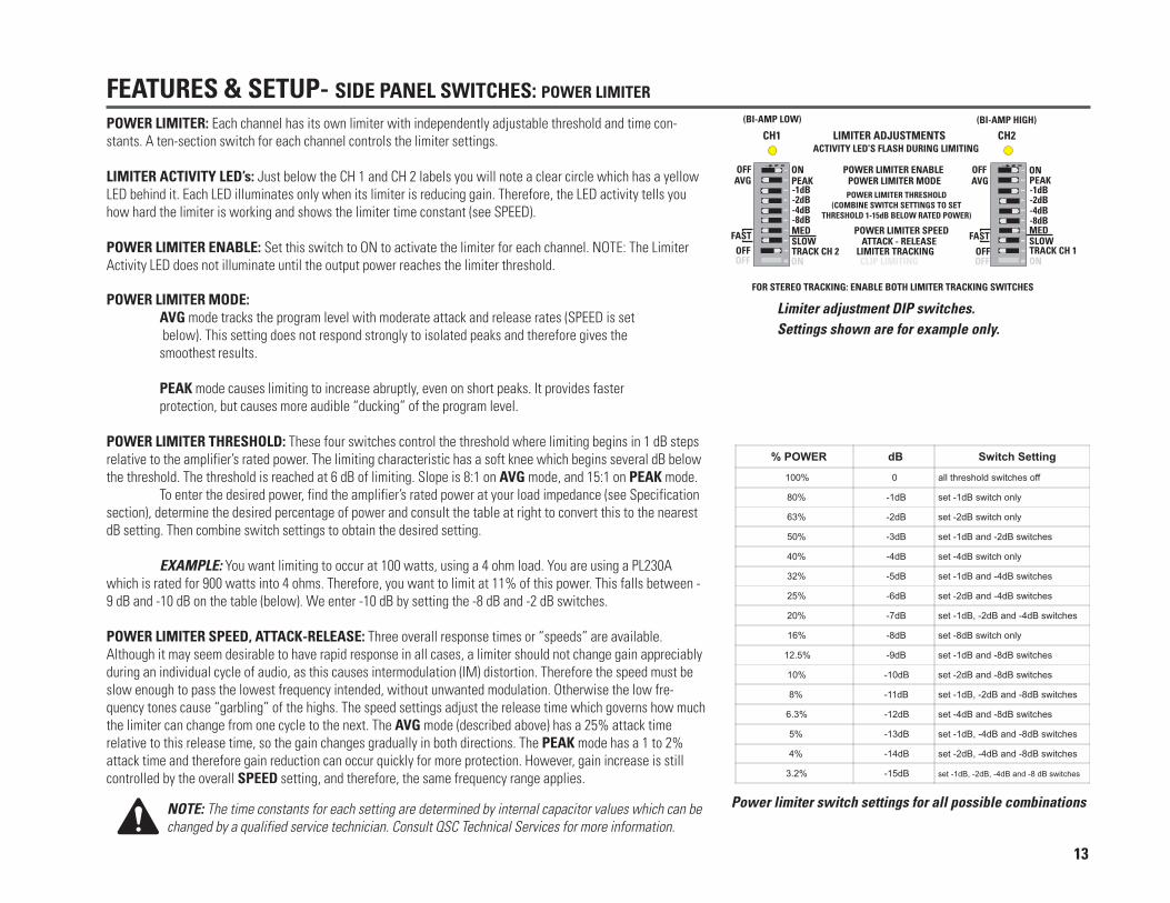
POWER LIMITER: Each channel has its own limiter with independently adjustable threshold and time con-stants. A ten-section switch for each channel controls the limiter settings.
LIMITER ACTIVITY LED’s: Just below the CH 1 and CH 2 labels you will note a clear circle which has a yellowLED behind it. Each LED illuminates only when its limiter is reducing gain. Therefore, the LED activity tells youhow hard the limiter is working and shows the limiter time constant (see SPEED).
POWER LIMITER ENABLE: Set this switch to ON to activate the limiter for each channel. NOTE: The LimiterActivity LED does not illuminate until the output power reaches the limiter threshold.
POWER LIMITER MODE:AVG mode tracks the program level with moderate attack and release rates (SPEED is set below). This setting does not respond strongly to isolated peaks and therefore gives thesmoothest results.
PEAK mode causes limiting to increase abruptly, even on short peaks. It provides fasterprotection, but causes more audible “ducking” of the program level.
POWER LIMITER THRESHOLD: These four switches control the threshold where limiting begins in 1 dB stepsrelative to the amplifier’s rated power. The limiting characteristic has a soft knee which begins several dB belowthe threshold. The threshold is reached at 6 dB of limiting. Slope is 8:1 on AVG mode, and 15:1 on PEAK mode.
To enter the desired power, find the amplifier’s rated power at your load impedance (see Specificationsection), determine the desired percentage of power and consult the table at right to convert this to the nearestdB setting. Then combine switch settings to obtain the desired setting.
EXAMPLE: You want limiting to occur at 100 watts, using a 4 ohm load. You are using a PL230Awhich is rated for 900 watts into 4 ohms. Therefore, you want to limit at 11% of this power. This falls between -9 dB and -10 dB on the table (below). We enter -10 dB by setting the -8 dB and -2 dB switches.
POWER LIMITER SPEED, ATTACK-RELEASE: Three overall response times or “speeds” are available.Although it may seem desirable to have rapid response in all cases, a limiter should not change gain appreciablyduring an individual cycle of audio, as this causes intermodulation (IM) distortion. Therefore the speed must beslow enough to pass the lowest frequency intended, without unwanted modulation. Otherwise the low fre-quency tones cause “garbling” of the highs. The speed settings adjust the release time which governs how muchthe limiter can change from one cycle to the next. The AVG mode (described above) has a 25% attack timerelative to this release time, so the gain changes gradually in both directions. The PEAK mode has a 1 to 2%attack time and therefore gain reduction can occur quickly for more protection. However, gain increase is stillcontrolled by the overall SPEED setting, and therefore, the same frequency range applies.
NOTE: The time constants for each setting are determined by internal capacitor values which can bechanged by a qualified service technician. Consult QSC Technical Services for more information.
Limiter adjustment DIP switches.Settings shown are for example only.
Power limiter switch settings for all possible combinations
13

FEATURES & SETUP- SIDE PANEL SWITCHES: POWER LIMITER (continued from previous page)
FAST- Set both POWER LIMITER SPEED switches to FAST. This setting produces 20 milliseconds (0.020 seconds) of release time. The AVG mode will produce 8 milliseconds ofattack time, and PEAK mode will produce less than 1 millisecond of attack time. This setting will have low distortion down to about 1 kHz. It is suitable for high frequency protection,but will cause a distinctly “muddy” effect when used on full range material.
MED- Set the upper POWER LIMITER SPEED switch to MED and the lower switch to FAST. This setting produces 200 milliseconds of release time. The AVG mode produces 80milliseconds of attack time and the PEAK mode produces 10 milliseconds of attack time. This setting is the fastest possible setting for full range material and may still produce someIM distortion for extremely low frequencies.
SLOW- Set the lower POWER LIMITER SPEED switch to SLOW and the upper switch to FAST. This setting provides 4 seconds of release time. The AVG mode produces 1.6second of attack time and the PEAK mode produces 180 milliseconds of attack time. This setting will change the gain very gradually in the AVG mode, and sudden peaks may clip for1 to 2 seconds. The PEAK mode will push overloads down quickly, but recovery time will still take many seconds.
14
POWER LIMITER TRACKING- Each channel’s power limiter operates independently, with its own threshold and time constants.
Four tracking modes are available for your use:
1- No Tracking-- switch section 9 of both limiter adjustment DIPs should be set to OFF. This is the “usual” mode where neither channel’s limiting effects the other.
2- CH 1 tracks the limiter activity of CH 2-- switch section 9 of channel 1’s limiter adjustment DIPs should be set to TRACK CH 2 and switch section 9 of channel 2’s limiteradjustment DIPs should be set to OFF. This tracking mode is not often used, but is applied to paging environments with high ambient noise levels. Limiting on channel 2 will causelimiting to occur on channel 1. Channel 2 is set up for a vocal-range horn and carries the voice page; its limiter is set for MED speed and PEAK mode with a power threshold andgain setting that produces proper paging level. Channel 1 is set up for a full-range music speaker with its level set for comfortable listening against the ambient noise. When apage drives channel 2 into limiting, channel 1 is driven “down” also, making the page more audible against the background noise. Some experimentation with channel 2’s gain andthreshold will be required for best performance with a range of paging voices & levels.
3- CH 2 tracks the limiter activity of CH 1 (bi-amp tracking) -- switch section 9 of channel 2’s limiter adjustment DIPs should be set to TRACK CH 1 and switch section 9 ofchannel 1’s limiter adjustment DIPs should be set to OFF. This tracking mode is useful for high frequency bi-amping , using fast protection on the horn without “ducking” the lowfrequencies. When used carefully, this mode can protect each driver in a two-way system , while preserving musical dynamics and balance.
We offer the following suggestions as a starting point for bi-amp tracking:
TWO-WAY SPEAKER WITH A FAIRLY HIGH CROSSOVER FREQUENCY- Most of these systems have a large cone low frequency driver and a comparatively delicate high frequencydriver. The limiting is tailored for each driver; higher power threshold and slower limiter speed for the low frequency driver and a lower power threshold and faster limiter speed forthe high frequency driver.
The low frequency driver can handle short time overloads, so its limiter can be set to the slower responding AVG (average) mode with MED to SLOW overall limiting times. Shortpeaks may clip, but the overall limiting will be smooth and gradual with no low frequency distortion and a minimum of “ducking”. If there is too much clipping, try the CLIPLIMITER or use the PEAK mode and MED speed.
FEATURES & SETUP- SIDE PANEL SWITCHES: CLIP LIMITER
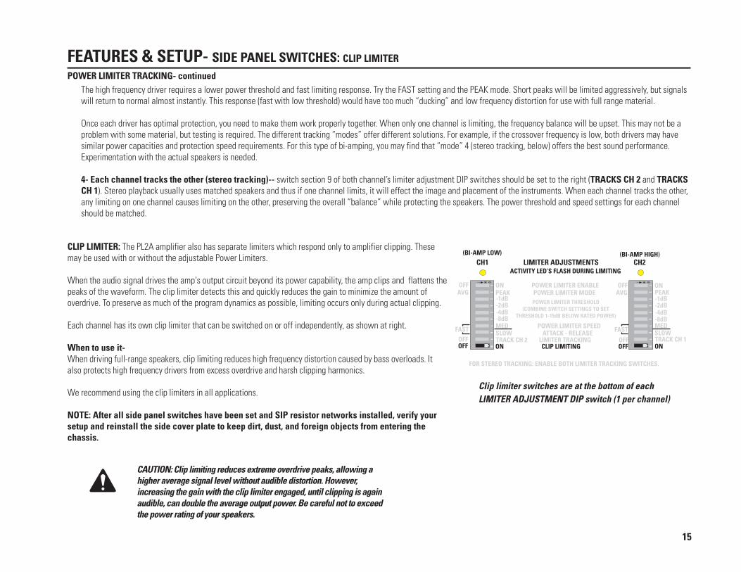
CLIP LIMITER: The PL2A amplifier also has separate limiters which respond only to amplifier clipping. Thesemay be used with or without the adjustable Power Limiters.
When the audio signal drives the amp's output circuit beyond its power capability, the amp clips and flattens thepeaks of the waveform. The clip limiter detects this and quickly reduces the gain to minimize the amount ofoverdrive. To preserve as much of the program dynamics as possible, limiting occurs only during actual clipping.
Each channel has its own clip limiter that can be switched on or off independently, as shown at right.
When to use it-When driving full-range speakers, clip limiting reduces high frequency distortion caused by bass overloads. Italso protects high frequency drivers from excess overdrive and harsh clipping harmonics.
We recommend using the clip limiters in all applications.
NOTE: After all side panel switches have been set and SIP resistor networks installed, verify yoursetup and reinstall the side cover plate to keep dirt, dust, and foreign objects from entering thechassis.
CAUTION: Clip limiting reduces extreme overdrive peaks, allowing ahigher average signal level without audible distortion. However,increasing the gain with the clip limiter engaged, until clipping is againaudible, can double the average output power. Be careful not to exceedthe power rating of your speakers.
Clip limiter switches are at the bottom of eachLIMITER ADJUSTMENT DIP switch (1 per channel)
15
POWER LIMITER TRACKING- continuedThe high frequency driver requires a lower power threshold and fast limiting response. Try the FAST setting and the PEAK mode. Short peaks will be limited aggressively, but signalswill return to normal almost instantly. This response (fast with low threshold) would have too much “ducking” and low frequency distortion for use with full range material.
Once each driver has optimal protection, you need to make them work properly together. When only one channel is limiting, the frequency balance will be upset. This may not be aproblem with some material, but testing is required. The different tracking “modes” offer different solutions. For example, if the crossover frequency is low, both drivers may havesimilar power capacities and protection speed requirements. For this type of bi-amping, you may find that “mode” 4 (stereo tracking, below) offers the best sound performance.Experimentation with the actual speakers is needed.
4- Each channel tracks the other (stereo tracking)-- switch section 9 of both channel’s limiter adjustment DIP switches should be set to the right (TRACKS CH 2 and TRACKSCH 1). Stereo playback usually uses matched speakers and thus if one channel limits, it will effect the image and placement of the instruments. When each channel tracks the other,any limiting on one channel causes limiting on the other, preserving the overall “balance” while protecting the speakers. The power threshold and speed settings for each channelshould be matched.

FEATURES & SETUP- SIDE PANEL: CROSSOVER & DELAY NETWORK SELECTION & INSTALLATION
SIP RESISTOR NETWORK INSTALLATION GUIDELINES AND SELECTIONINFORMATION
Your PL2A amplifier is shipped configured to order with SIP networks installed. Ifthe factory set up is not applicable for your application,then you will need toknow your desired crossover frequency and low frequency delay time in order toselect the corresponding SIP resistor network values. Refer to the selectionchart, below, for nominal crossover frequency and delay values.
A general guideline would be to never use a larger value of delay SIP thanthat used for the crossover. After choosing the desired values from theselection chart, locate the plastic bag containing the SIP networks and locatethe desired value.
DECODING SIP NETWORK RESISTANCE VALUES(see note below decoding chart)
NOTE: Due to the number of manufacturers of SIP resistor networks, we can notpossibly provide examples of all the various part number marking schemes. We haveprovided the three most common marking schemes, above. If the SIP networks you havereceived do not conform to one of the above schemes, QSC’s Technical ServicesDepartment will be glad to assist you in determining the resistance value of your SIPs.Alternatively, you could measure the resistance value with a multimeter; simply set youmeter to the proper resistance range and connect your multimeter’s leads to the first twopins of either end to obtain the value.
16

FEATURES & SETUP- SIDE PANEL: CROSSOVER & DELAY NETWORK SELECTION & INSTALLATION
The SIPs may be installed “either way”. TheSIPs are symmetrical and thus performidentically no matter which end points to theleft or right. This completely eliminates“polarity” errors that might otherwise arise.
The side cover plate must be removed to accessthe SIP sockets. Be sure to reinstall the sidecover plate after installing the SIPs.
Before installing the SIP (as shown right) ensurethat the pins are straight. This will easeinsertion into the jack and help to avoiddamaging the pins due to misaligned insertion.
NOTE: Reinstall the sidecover plate after SIPinstallation to keep dust, dirt,and foreign objects fromentering the internalcircuitry of the amplifier.Failure to do so could resultin damage to the amplifiershould any such materialenter the chassis.
17
Turn the power to the amplifier off before removing or installing SIPs!

GAIN CONTROLSThe gain controls are detented (21 steps) for repeatable adjustment. Surrounding the gain control knob, theattenuation level is shown in dB. Maximum gain depends on the model and the GAIN-SENSITIVITY SELECTswitch setting. For full details, see the specification section.
FRONT PANEL LED INDICATORSAt full brightness, the green POWER LED indicates that the amplifier is operating. Half brightness indicates theamp is in its start-up sequence or that the amplifier is in STANDBY mode.As the input signal strength increases, the green SIGNAL, -20dB, and amber -10dB LED indicators lightrespectively at 0.1%, 1% and 10% of full power. The red CLIP LED indicator flashes during overload (clipping). Abright, steady glow indicates protective muting. If this occurs during use, see the Troubleshooting section. Theyellow BRIDGE LED illuminates when the amp is in BRIDGE mode. The blue BI-AMP LED illuminates when theamplifier is in BI-AMP mode. The orange PARALLEL LED illuminates when the amp is in PARALLEL input mode.
DATAPORT CONNECTORThe PL2A amplifier features a QSC DataPort connector which connects to accessory products to enhance your amplifier application.The CM16a Amplifier Network Monitor can remotely control and monitor your PL2A amplifier. The DSP-3 digital signal processor canmount directly to the rear of your PL2A amplifier, adding an incredible amount of processing power in a small, powerful module at avery competitive price.
FEATURES & SETUP: DATAPORT, FRONT PANEL LED INDICATORS, GAIN CONTROLS
Front panel: gain controls and indicator LED’s forsignal level, clip indication, power status indication,and operating mode (bridge, parallel, bi-amp)
DataPort connector location
WARNING: The PL2A amplifiers use a rear panel switch ( DATAPORT INPUT SIGNAL switch) to control the inputsignal from the DataPort. When using a DataPort-connected accessory, be sure to set this switch to PRE PROC(blue confirmation LED illuminated) or POST PROC (yellow confirmation LED illuminated) as desired. This switchmust be in the OFF position (green confirmation LED illuminated) to use the regular inputs.
OTHER ACCESSORIES-Accessories for the PL2A amplifiers are available through your local distributor or directly from QSC. For accessory information,contact QSC's Technical Services Department or your QSC representative. Check QSC’s web page for the latest product information.
18

INSTALLATION: RACK MOUNTING AND MOUNTING DIMENSIONSBefore installing into equipment rack: ensure that all side-access DIPswitches and crossover SIPs are setup as desired. They will beimpossible (or extremely difficult) to change after the amplifier isinstalled in the rack. The side cover plate should be installed to keepdust and foreign material out of the chassis.
Securing the Front Ears to the Rack RailsUse four screws and washers when mounting the PL2A amplifier to the front rails.Support the weight of the amplifier while securing it to the rails to avoid bending ordistorting the front rack mount ears.
Supporting the Rear of the AmplifierSupporting the amplifier at the rear is important, especially for mobile and touringuse. Rear rack mounting ear kits are an accessory item and are available from QSC’sTechnical Services Department or from your dealer or distributor.The rear rack mounting ear kit may be installed in twodifferent ways.
Method 1- The amplifier is first installed from the frontof the rack and then the ears are secured directly to theamplifier with two machine screws as shown, left. Thenthe ears are secured to the rails using ordinary railhardware.
Method 2- The amplifier is first installed from the frontof the rack. Then, the accessory rear ears are positionedon the rear rack rails and secured. The pin installationposition can now be selected. Install the pin so that it fitswell into the slot provided on the amplifier's rearmounting tab.
PL2 A rack mounting installation and majordimensions
PL2 A dimensional details
19
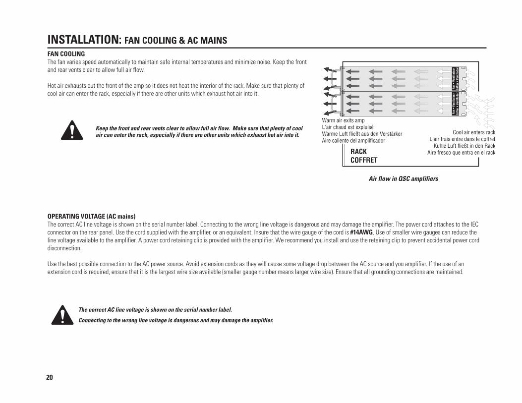
INSTALLATION: FAN COOLING & AC MAINSFAN COOLINGThe fan varies speed automatically to maintain safe internal temperatures and minimize noise. Keep the frontand rear vents clear to allow full air flow.
Hot air exhausts out the front of the amp so it does not heat the interior of the rack. Make sure that plenty ofcool air can enter the rack, especially if there are other units which exhaust hot air into it.
Keep the front and rear vents clear to allow full air flow. Make sure that plenty of coolair can enter the rack, especially if there are other units which exhaust hot air into it.
The correct AC line voltage is shown on the serial number label.
Connecting to the wrong line voltage is dangerous and may damage the amplifier.
OPERATING VOLTAGE (AC mains)The correct AC line voltage is shown on the serial number label. Connecting to the wrong line voltage is dangerous and may damage the amplifier. The power cord attaches to the IECconnector on the rear panel. Use the cord supplied with the amplifier, or an equivalent. Insure that the wire gauge of the cord is #14AWG. Use of smaller wire gauges can reduce theline voltage available to the amplifier. A power cord retaining clip is provided with the amplifier. We recommend you install and use the retaining clip to prevent accidental power corddisconnection.
Use the best possible connection to the AC power source. Avoid extension cords as they will cause some voltage drop between the AC source and you amplifier. If the use of anextension cord is required, ensure that it is the largest wire size available (smaller gauge number means larger wire size). Ensure that all grounding connections are maintained.
Air flow in QSC amplifiers
20
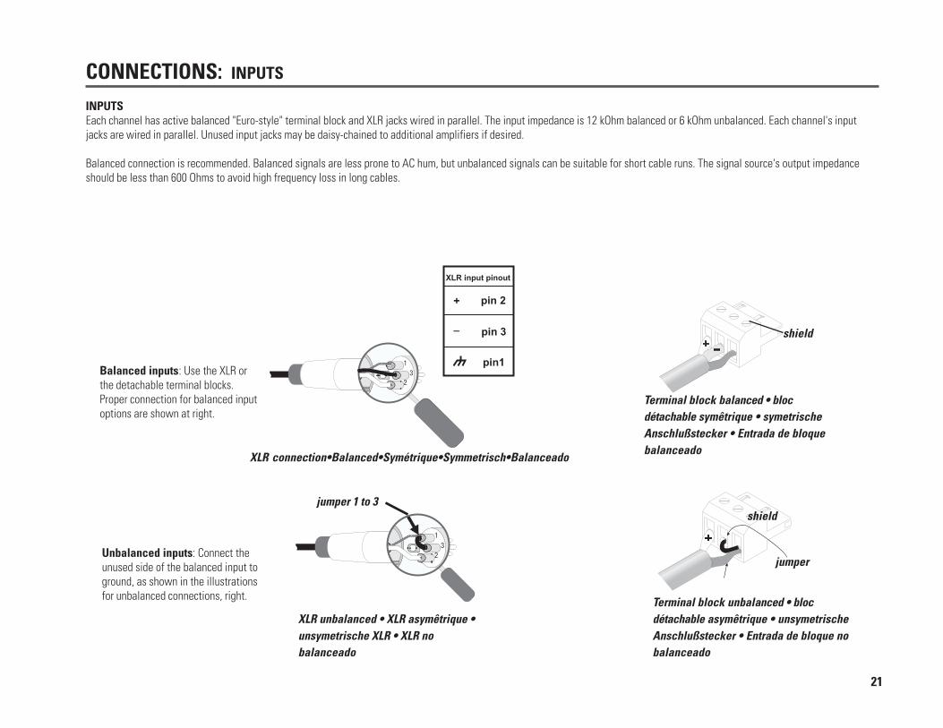
INPUTSEach channel has active balanced "Euro-style" terminal block and XLR jacks wired in parallel. The input impedance is 12 kOhm balanced or 6 kOhm unbalanced. Each channel's inputjacks are wired in parallel. Unused input jacks may be daisy-chained to additional amplifiers if desired.
Balanced connection is recommended. Balanced signals are less prone to AC hum, but unbalanced signals can be suitable for short cable runs. The signal source's output impedanceshould be less than 600 Ohms to avoid high frequency loss in long cables.
Balanced inputs: Use the XLR orthe detachable terminal blocks.Proper connection for balanced inputoptions are shown at right.
Unbalanced inputs: Connect theunused side of the balanced input toground, as shown in the illustrationsfor unbalanced connections, right.
XLR unbalanced • XLR asymêtrique •unsymetrische XLR • XLR nobalanceado
Terminal block unbalanced • blocdétachable asymêtrique • unsymetrischeAnschlußstecker • Entrada de bloque nobalanceado
XLR connection•Balanced•Symétrique•Symmetrisch•Balanceado
Terminal block balanced • blocdétachable symêtrique • symetrischeAnschlußstecker • Entrada de bloquebalanceado
CONNECTIONS: INPUTS
jumper 1 to 3shield
jumper
shield
21

Speakon™ Outputs: The Speakon connector is designed specially for high-power speaker connections. It locks in place, prevents shock hazard, and assures the correct polarity. Foreasier insertion, use the newer-style NL4FC Speakon connectors with quick lock thumb latches.
The upper Speakon jack (CH1) has both Channel 1 and Channel 2 outputs, so it is especially useful for parallel, bi-amp, or bridged mono operation. The other Speakon carries onlyChannel 2’s output. See the illustrations below.
2 channels/canaux/Kanäle/canales & 2 Speakons(Stereo, bi-amp, or parallel mode; Modes stéreo, bi-amp ou
parallèle; Stereo-, Bi-amp- oder Parallelbetrieb; Modos estéreo,bi-amp o paralelo)
2 channels/canaux/Kanäle/canales & 1 Speakon(Stereo, bi-amp, or parallel mode; Modes stéreo, bi-amp ou
parallèle; Stereo-, Bi-Amp- oder Parallelbetrieb; Modos estéreo,bi-amp o paralelo)
Bridged mono • Mono ponté • Monobrückenbetrieb •Mono puente
SPEAKER CABLING: Always use the largest wire size and shortest length of wire practical for any given installation. Larger wire sizes and shorter lengths minimize power loss anddegradation of damping factor. Do not place speaker cables next to input wiring.
CONNECTIONS: OUTPUTS
BRIDGED-MONO PRECAUTIONS:
Do Not Use 2 Ohm Loads in Bridge Mono Mode! 4 Ohms is the minimum impedance for bridge mono operation!
This mode puts a high demand on the amplifier and speaker. Excessive clipping may cause protective muting or speaker damage.Ensure the speaker has a sufficient power rating.
Output voltages greater than 100 volts rms are available between the amplifier's bridged terminals. CLASS 3 wiring methods, asspecified in accordance with national (NEC) and local codes, must be used to connect the speaker. To prevent electric shock, donot operate the amplifier with any conductors of the speaker cable exposed.
OUTPUTS: PL2A amplifiers offer a choice of output connections; Neutrik NL4MD Speakon jacks and "touch-proof" binding post outputs.
22

CONNECTIONS: OUTPUTSBinding post outputs
Three connection methods may be used to connect to the binding post output terminals:
• wire inserted from the side then the retaining nut is tightened
• spade terminal inserted from the side then the knurled retaining nut is tightened
• banana plug inserted into the post
Banana plug capability is provided on non-European models ONLY!
Bridged mono • Mono ponté •Monobrückenbetrieb • Mono puente
Stereo, bi-amp, or parallel mode
Modes stéreo, bi-amp ou parallèle
Stereo-, Bi-amp- oder Parallelbetrieb
Modos estéreo, bi-amp o paralelo
Binding Post strip length, spade terminal size andconnection methods
23

REMOVING THE SECURITY PANEL1. Use an angle 9/64" or 3.5 mm hex key to loosen the screw.2. Use a small flat screwdriver to lift the right end of the security panel so that its tabs are free of the slots in the front panel.3. Slide the security panel to the left until you can lift the left end free; slide the panel to the left to remove it from behind the screw.4. Reinstall the gain control knobs by aligning the flat spot on the control shaft with the flat spot on the knob's shaft opening and pushing the knob firmly onto the shaft.
SECURITY PANEL
After setting the gain controls, you can install the security panel to prevent tampering and accidental misadjustment. After the knobs have been removed and the gain setting checked,install the security panel as shown in the general illustration to the left and on next page.
Right: a POWERLIGHT 2A amplifier with security panel installedA droite: le panneau avant avec plaquette protectrice installéeRechts: ein POWERLIGHT 2A-Verstärker mit SicherheitsabdeckungDerecha: un amplificador PL2 Acon el panel de seguridad instalado
SECURITY PANEL USE & INSTALLATION
Step 1 Step 2 Step 3 Step 4 Step 5
INSTALLING THE SECURITY PANEL1. Remove the gain control knobs. Do not pry on the knob as damage to the gain control could result.2. Use a 9/64" or 3.5 mm hex key to loosen the screw.3. Slide the right end of the security panel under the screw head.4. Insert the tabs into the keyed portion of the ventilation slots, then slide the panel to the right so it locks in the slot.5. Align the right end of the security panel with the chassis openings; tighten the screw to secure the panel. Do not over tighten.
NOTE: The PL2A security panel has a viewing hole for the blue BI-AMP LED. DO NOT USE the PL2security panel as it has no BI-AMP LED hole. The use of the incorrect security panel may result indamage to the BI-AMP LED. Ensure PL2A security panels are used with PL2A amplifiers.
24

OPERATION
NORMAL OPERATING LEVELS
The amp's protective muting system guards against excessive internal temperatures. With normal ventilation and 4 to 8 ohm loads, the amplifier will handle any signal level includingoverdrive. Lower load impedances and higher signal levels produce more internal heating. When using 2 ohm loads, frequent or prolonged clipping may trigger power cutback orprotective muting.
BRIDGE mode doubles the output impedance of the amp; 4 ohms is the minimum load impedance. Heavy clipping may cause muting. If this happens, see Troubleshooting section.
AC POWER SWITCHBefore applying power, check all connections and turn down the gain controls. The "soft start" sequence starts with the POWER indicatorLED at half brightness. A few seconds later the fan starts, the POWER indicator fully illuminates and the amplifier mutes for two seconds.The CLIP LEDs will glow bright red. When the CLIP LEDs go out, the amplifier is ready.
FRONT PANEL LED INDICATORSAt full brightness, the green POWER LED indicates that the amplifier is operating. Half brightness indicates theamp is in its start-up sequence or STANDBY mode.
As the input signal strength increases, the green SIGNAL, -20dB, and amber -10dB LED indicators lightrespectively at 0.1%, 1% and 10% of full power.
The red CLIP LED indicator flashes during overload (clipping). A bright, steady glow indicates protective muting;if this occurs during use, see Troubleshooting.
The yellow BRIDGE LED illuminates when the MODE switch is set to BRIDGE.
The blue BI-AMP LED illuminates when the MODE switch is set to BI-AMP.
The orange PARALLEL LED illuminates when the INPUT CONFIGURATION switch is set to PARALLEL.
GAIN CONTROLSTurn down the gain controls before applying power. The gain controls are detented 21 steps for repeatable adjustment. Surrounding the gain control knob, the attenuation level is shownin dB. The gain structure may be selected on the PL2A. On the rear panel you will find a switch labeled GAIN-SENSITIVITY SELECT; you may select from +4 dB input sensitivity, 32 dBor 26 dB of voltage gain.
Front panel: gain controls and indicator LED’s forsignal level, clip indication, power status indication,and operating mode (bridge, parallel, bi-amp)
25

Problem: NO SOUND• INDICATION: POWER INDICATOR NOT LIT
• Check the AC plug.• Confirm that the AC outlet works by plugging in another device. If too many amplifiers are used on one outlet, the
building's circuit breaker may trip and shut off power.• An overload in bridge mode may cause the amplifier to click off for three seconds, indicated by the half-bright
POWER LED, followed by a normal restart cycle. Check the load impedance (4 ohms minimum), or reduce signallevel.
• An amplifier which keeps shutting off may have a serious internal fault. Turn it off, remove AC power, and have theamplifier serviced by a qualified technician.
• INDICATION: SIGNAL LED NOT LIT• Ensure that the DATAPORT INPUT SIGNAL switch is in the proper position. If you are using the XLR or terminal
block inputs, it should be in the OFF position. If you are using the DATAPORT for your input signal, the switch shouldbe set to PRE PROC or POST PROC.
• If the green POWER indicator LED is at full brightness, yet the signal LEDs indicate no signal, check the input.Make sure the signal source is operating and try another input cable. Connect the source to another channel oramplifier to confirm its operation.
• INDICATION: SIGNAL LEDS RESPONDING TO SIGNAL LEVEL• If the green SIGNAL, -20 dB, and -10 dB indicators are lighting normally, the fault is somewhere between the amp
and the speaker. Check the speaker wiring for breaks. Try another speaker and cable.
• INDICATION: CLIP LEDS BRIGHT AND STEADY
The amplifier is in protective muting.
• One second of muting is normal when the amp is turned on or off.• Overheating will cause protective muting. The fan will be running at full speed and the chassis will be hot to the
touch; sound should resume within a minute as the amplifier cools to a safe operating temperature. Check forproper ventilation. If the fan isn't running at all, the amplifier requires servicing.
• INDICATION: CLIP LED FLASHING• If the red CLIP indicator flashes when signal is applied, the amplifier output may be shorted. Check the speaker
wiring for stray strands or breaks in the insulation.
TROUBLESHOOTING: NO SOUND
26

PROBLEM: DISTORTED SOUND
• INDICATION: CLIP LED FLASHING• If the red CLIP indicator flashes before all three signal indicators do, the load impedance is abnormally low or
shorted. Unplug each speaker one-by-one at the amplifier. If the CLIP LED goes out when you disconnect acable, that cable or speaker is shorted. Try another cable and speaker to locate the fault.
• INDICATION: CLIP INDICATOR NOT FLASHING• This could be caused by a faulty speaker or loose connection. Check the wiring and try another speaker.• The signal source may be clipping. Keep the amplifier gain controls at least halfway up so that the source does
not have to be overdriven.
PROBLEM: NO CHANNEL SEPARATION• Check the yellow PARALLEL or orange BRIDGE MONO LEDs on the front panel, which indicate the switch settings
on the back of the amplifier. Neither should be lit in dual-channel, bi-amp, or stereo use where different signals go toeach channel. Make sure the "Parallel Input" and "Bridge Mode" switches are OFF.
• Make sure other equipment in the signal path, such as mixers, preamps, etc., is set for stereo, not mono.
PROBLEM: CH 1 IS ALL LOW FREQUENCY MATERIAL & CH 2 IS ALL HIGH FREQUENCY MATERIAL• Check that the BI-AMP LED on the front panel is not illuminated. If it is, the MODE switch on the rear panel is in the
BI-AMP position. Move the MODE switch to the 2 CH position. This assumes you do not want to be in BI-AMP modeand that you are operating in a 2 channel mode.
PROBLEM: HISS• Unplug the amplifier input to confirm that the hiss is coming from the source or a device upstream; erratic or popping
noises indicate an electronic fault in the offending unit.• To keep the normal noise floor low, operate the primary signal source at full level, without clipping, and avoid boosting
the signal further between the source and the amplifier.
PROBLEM: SQUEALS AND FEEDBACK• Microphone feedback should be controlled with mixer controls. If noise continues to build up with zero mic gain, there
is a serious fault in the signal processors or cables. Working in succession from the signal source towards theamplifier, check each device in the signal path by reducing its gain or unplugging it.
PROBLEM: HUM• The PowerLightTM supply eliminates internal hum fields, but transformers in other magnetic devices may cause
hum. Move cabling and signal sources to identify "hot spots" in the system; then avoid those spots. Cables withfaulty shielding are a common entry point for hum. Use top quality cabling.
Magnetic field from power supplies in equipment caninduce hum into cabling that is located in the field. Ifhum is a problem, try relocating cabling so that isaway from power supplies, transformers and othermagnetic field producing devices.
TROUBLESHOOTING: DISTORTION, NO CHANNEL SEPARATION, HUM, HISS, FEEDBACK
27

TECHNICAL OVERVIEW: BLOCK DIAGRAM & OPERATIONAL DETAILS
An impressive amount oftechnology is packed "under thehood" of a PL2A amplifier.Thousands of watts of powerflow inches away from state-of-the-art low noise inputs.Precise circuit layout andthorough protection assurethat all of this activity occurssmoothly and safely. So, whatactually happens when youturn on the power switch?
Soft Start Sequence. Thefirst task is to charge theprimary energy reservoirwithout drawing a large surgecurrent. A special inrush limiterallows just enough current tocharge the energy bank inthree seconds. Meanwhile, alow-power switching supplyprovides power to start up themain supply. After threeseconds, a relay bypasses theinrush limiting and full poweroperation is enabled. Theaudio circuitry mutes for onesecond to eliminate start-upthumps. When the red CLIPlights go out, the amplifier isready for action.
PowerLight™ Technology. High current switching devices draw over 10,000 watts of peak power from the main energy reservoir, whichis replenished directly from the AC line for maximum stiffness. Conventional amplifiers must isolate the energy bank with a large ACtransformer, which weakens the flow of current, allows greater sag under load, and produces hum. The PowerLight supply performs voltageconversion at a very high frequency, allowing better coupling through a much smaller isolation transformer.
Block diagram of audio path in a PL2A amplifier
28
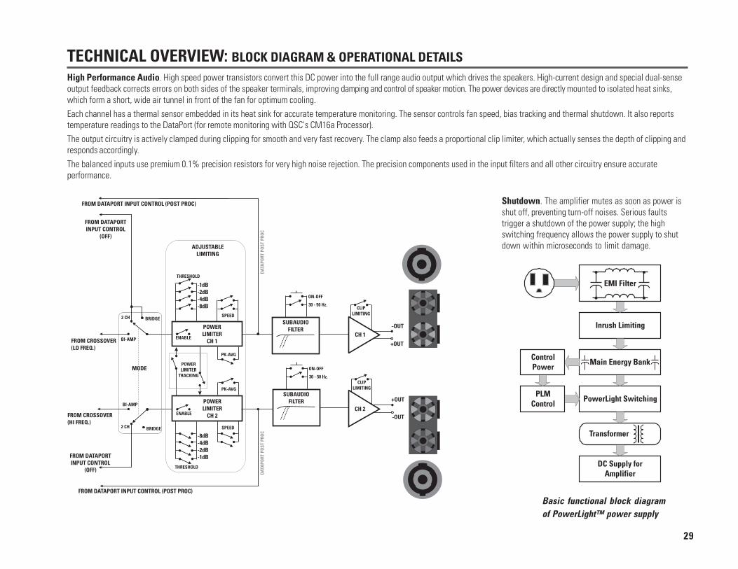
TECHNICAL OVERVIEW: BLOCK DIAGRAM & OPERATIONAL DETAILSHigh Performance Audio. High speed power transistors convert this DC power into the full range audio output which drives the speakers. High-current design and special dual-senseoutput feedback corrects errors on both sides of the speaker terminals, improving damping and control of speaker motion. The power devices are directly mounted to isolated heat sinks,which form a short, wide air tunnel in front of the fan for optimum cooling.Each channel has a thermal sensor embedded in its heat sink for accurate temperature monitoring. The sensor controls fan speed, bias tracking and thermal shutdown. It also reportstemperature readings to the DataPort (for remote monitoring with QSC's CM16a Processor).The output circuitry is actively clamped during clipping for smooth and very fast recovery. The clamp also feeds a proportional clip limiter, which actually senses the depth of clipping andresponds accordingly.The balanced inputs use premium 0.1% precision resistors for very high noise rejection. The precision components used in the input filters and all other circuitry ensure accurateperformance.
Basic functional block diagramof PowerLight™ power supply
Shutdown. The amplifier mutes as soon as power isshut off, preventing turn-off noises. Serious faultstrigger a shutdown of the power supply; the highswitching frequency allows the power supply to shutdown within microseconds to limit damage.
29
EMI Filter
Inrush Limiting
Main Energy Bank
PowerLight Switching
DC Supply forAmplifier
Transformer
ControlPower
PLMControl

PL218A PL224A PL230A PL236A
OUTPUT POWER in wattsFTC: 8 ohms per channel (20-20k Hz., 0.05% THD) 310 440 575 725
4 ohms per channel (20-20k Hz., 0.07% THD) 525 715 900 1100
EIA: 1 kHz 8 ohms per channel 350 475 625 800
@1% THD 4 ohms per channel 600 825 1050 1300
2 ohms per channel 900 1200 1500 1850
Bridged Mono:
16 ohms, 20–20k Hz, 0.1% THD 650 900 1200 15008 ohms, 20–20k Hz, 0.1% THD 1100 1500 2000 24004 ohms, 1 kHz, 1% THD 1800 2400 3000 3600
DYNAMIC HEADROOM (all models) less than 2 dB at 4 ohms
DISTORTION (all models)SMPTE-IM Less than 0.01%Typical, 10 dB below rated power, 20-20k Hz. <0.025%Typical, full rated power, 1k Hz. and below <0.025%
FREQUENCY RESPONSE (all models) 20 Hz to 20 kHz, ±0.2 dB(at 10 dB below rated output power) -3 dB points: 8 Hz and 65 kHz
DAMPING FACTOR (all models) Greater than 500
SIGNAL to NOISE (unweighted, 20-20k Hz.) -103 dB -103 dB -103 dB -103 dB
VOLTAGE GAIN Selectable from 26dB or 32 dB voltage gain (or a 1.2 Vrms input sensitivity) by the GAIN-SENSITIVITY SELECT switch
INPUT SENSITIVITY, V RMS switch position 26dB 1.2Vrms 32dB 26dB 1.2Vrms 32dB 26dB 1.2Vrms 32dB 26dB 1.2Vrms 32dB
for rated power into 8 ohms 2.57 1.28 1.28 3.05 1.20 1.53 3.84 1.22 1.93 3.95 1.24 1.98
for rated power into 4 ohms 2.37 1.18 1.18 2.97 1.10 1.39 3.41 1.08 1.71 3.45 1.09 1.73
INPUT CLIPPING, Vrms (all models) +22dBu
INPUT IMPEDANCE (all models) 6k ohms unbalanced12k ohms balanced
CONTROLS (all models) Front: AC switch, CH 1 and CH 2 gain knobsBack: Slide switches with LED confirmation for: Input Configuration, Mode, DataPort Input Signal assignment and Gain-Sensitivity SelectSide: SIP networks for crossover frequency and low frequency delay; push-button toggle switch for Subaudio Filter; DIP switches for Subaudio Frequency select, Lo Frequency delay enable/off, HF Attenuation 0 to -15 db adjust, Horn Boost 0 to +14 dB adjust. “Per Channel” switches: Power Limiter enable/off, Power Limiter Mode peak/average, Power Limiter Threshold 0 to -15dB adjust, Power Limiter attack & release time fast-medium-slow, Power Limiter tracking none/bi-amp (CH 2 tracks CH 1)/”reverse” bi-amp (CH 1 tracks CH 2)/stereo (each channel tracks the other), and Clip Limiting on/off
S P E C I F I C AT I O N S
30
S P E C I F I C AT I O N S PL218A PL224A PL230A PL236A
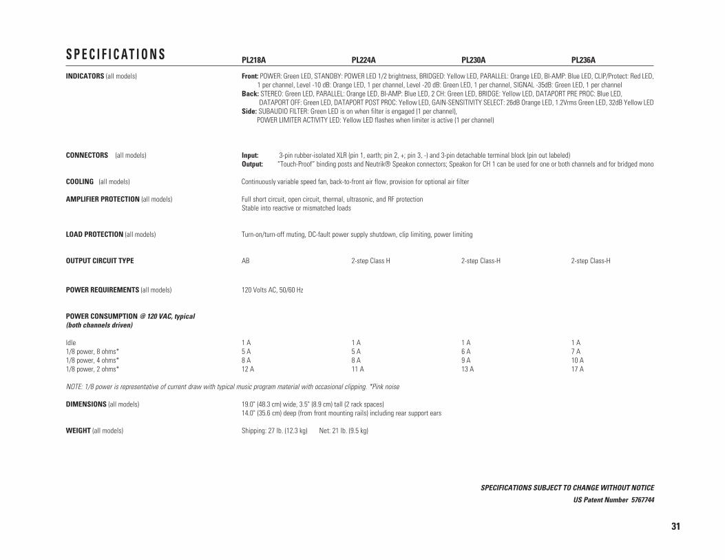
INDICATORS (all models) Front: POWER: Green LED, STANDBY: POWER LED 1/2 brightness, BRIDGED: Yellow LED, PARALLEL: Orange LED, BI-AMP: Blue LED, CLIP/Protect: Red LED, 1 per channel, Level -10 dB: Orange LED, 1 per channel, Level -20 dB: Green LED, 1 per channel, SIGNAL -35dB: Green LED, 1 per channelBack: STEREO: Green LED, PARALLEL: Orange LED, BI-AMP: Blue LED, 2 CH: Green LED, BRIDGE: Yellow LED, DATAPORT PRE PROC: Blue LED, DATAPORT OFF: Green LED, DATAPORT POST PROC: Yellow LED, GAIN-SENSITIVITY SELECT: 26dB Orange LED, 1.2Vrms Green LED, 32dB Yellow LEDSide: SUBAUDIO FILTER: Green LED is on when filter is engaged (1 per channel), POWER LIMITER ACTIVITY LED: Yellow LED flashes when limiter is active (1 per channel)
CONNECTORS (all models) Input: 3-pin rubber-isolated XLR (pin 1, earth; pin 2, +; pin 3, -) and 3-pin detachable terminal block (pin out labeled)Output: “Touch-Proof” binding posts and Neutrik® Speakon connectors; Speakon for CH 1 can be used for one or both channels and for bridged mono
COOLING (all models) Continuously variable speed fan, back-to-front air flow, provision for optional air filter
AMPLIFIER PROTECTION (all models) Full short circuit, open circuit, thermal, ultrasonic, and RF protectionStable into reactive or mismatched loads
LOAD PROTECTION (all models) Turn-on/turn-off muting, DC-fault power supply shutdown, clip limiting, power limiting
OUTPUT CIRCUIT TYPE AB 2-step Class H 2-step Class-H 2-step Class-H
POWER REQUIREMENTS (all models) 120 Volts AC, 50/60 Hz
POWER CONSUMPTION @ 120 VAC, typical(both channels driven)
Idle 1 A 1 A 1 A 1 A1/8 power, 8 ohms* 5 A 5 A 6 A 7 A1/8 power, 4 ohms* 8 A 8 A 9 A 10 A1/8 power, 2 ohms* 12 A 11 A 13 A 17 A
NOTE: 1/8 power is representative of current draw with typical music program material with occasional clipping. *Pink noise
DIMENSIONS (all models) 19.0" (48.3 cm) wide, 3.5" (8.9 cm) tall (2 rack spaces)14.0" (35.6 cm) deep (from front mounting rails) including rear support ears
WEIGHT (all models) Shipping: 27 lb. (12.3 kg) Net: 21 lb. (9.5 kg)
SPECIFICATIONS SUBJECT TO CHANGE WITHOUT NOTICE
US Patent Number 5767744
31
Disclaimer
QSC Audio Products, Inc. is not
liable for any damage to speakers,
amplifiers, or any other equipment
that is caused by negligence or
improper installation and/or use of
the PL2A amplifier.
Product Warranty
QSC guarantees the PL2A to be free
from defective material and/or
workmanship for a period of three
years from the date of sale, and will
replace defective parts and repair
malfunctioning products under this
warranty when the defect occurs
under normal installation and use—
provided the unit is returned to our
factory via prepaid transportation
with a copy of the proof of purchase,
i.e., sales receipt. This warranty
provides that examination of the
returned product must indicate, in
our judgment, a manufacturing
defect. This warranty does not
extend to any product which has
been subjected to misuse, neglect,
accident, improper installation, or
where the date code has been
removed or defaced.
(USA only; other countries, seeyour dealer or distributor)
Mailing address / Adresse postale / Postanschrift / Dirección postal: QSC Audio Products, Inc.
1675 MacArthur BoulevardCosta Mesa, CA 92626-1468 USA
Telephone Numbers / Numéros de téléphone / Telefonnummern / Números de teléfono:
Main Number / Numéro principal / Hauptnummer / Número principal +(714) 754-6175
Sales Direct Line / Ligne directe ventes / Verkauf-Direkt / Línea directo ventas +(714) 957-7100
Sales & Marketing / Ventes & marketing / Verkauf u. Marketing / Ventas y marketing (800) 854-4079 (toll-free in U.S.A. only)
(sans frais aux É-U seulement)
(zollfrei nur beim USA)
(sin costo en EE. UU. solamente)
Customer Service / Service à la clientèle / Kundendienst / Servicio a la clientela +(714) 957-7150(800) 772-2834 (toll-free in U.S.A. only)
(sans frais aux É-U seulement)
(zollfrei nur beim USA)
(sin costo en EE. UU. solamente)
Facsimile Numbers / Numéros de télécopieur / Telefaxnummern / Número de FAX:Sales & Marketing FAX / Télécopie ventes & marketing / Telefax der Verkauf u. Marketing / FAX ventas y marketing
+(714) 754-6174
Customer Service FAX / Télécopie service à la clientèle / Kundendienst-Telefax / FAX servicio a la clientela+(714) 754-6173
World Wide Web: www.qscaudio.com
E-mail: [email protected]
WARRANTY HOW TO CONTACT QSC AUDIO PRODUCTS
WARRANTY INFORMATION & HOW TO CONTACT QSC AUDIO PRODUCTS
32

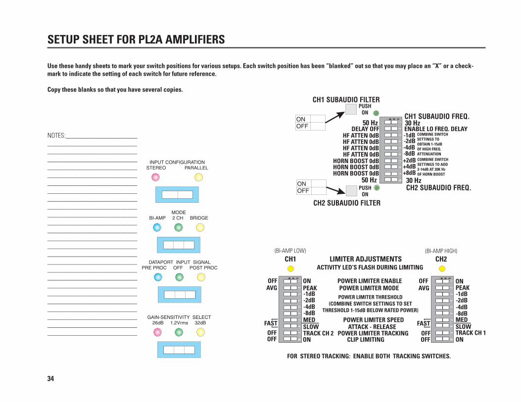
SETUP SHEET FOR PL2A AMPLIFIERS
Use these handy sheets to mark your switch positions for various setups. Each switch position has been “blanked” out so that you may place an “X” or a check-mark to indicate the setting of each switch for future reference.
Copy these blanks so that you have several copies.
NOTES:______________________________________________________________________________________________________________________________________________________________________________________________________________________________________________________________________________________________________________________________________________________________________________________________________________________________________________________________________________________________________________________________________________________________________________________________________________________________________________________________________________________________________________________________
33
SETUP SHEET FOR PL2A AMPLIFIERS
Use these handy sheets to mark your switch positions for various setups. Each switch position has been “blanked” out so that you may place an “X” or a check-mark to indicate the setting of each switch for future reference.
Copy these blanks so that you have several copies.
NOTES:______________________________________________________________________________________________________________________________________________________________________________________________________________________________________________________________________________________________________________________________________________________________________________________________________________________________________________________________________________________________________________________________________________________________________________________________________________________________________________________________________________________________________________________________
34

QSC Audio Products, Inc. 1675 MacArthur Boulevard Costa Mesa, California 92626 USA“QSC” and the QSC logo are registered with the U.S. Patent and Trademark Office.
©2000, 2007 QSC Audio Products, Inc.