Embed Size (px)
Citation preview
()
■ ■ ■ ■ ■ ■ ■
■ ■ ■ ■ ■ ■ ■
■ ■ ■ ■ ■ ■ ■
■ ■ ■ ■ ■ ■ ■
■ ■ ■ ■ ■ ■ ■
■ ■ ■ ■ ■ ■ ■
■ ■ ■ ■ ■ ■ ■
■ ■ ■ ■ ■ ■ ■
■ ■ ■ ■ ■ ■ ■
■ ■ ■ ■ ■ ■ ■
■ ■ ■ ■ ■ ■ ■
■ ■ ■ ■ ■ ■ ■
■ ■ ■ ■ ■ ■ ■
■ ■ ■ ■ ■ ■ ■U s e r ’ s G u i d e
EXPRESS5800/120Ee

xxx

()
■ ■ ■ ■ ■ ■ ■
■ ■ ■ ■ ■ ■ ■
■ ■ ■ ■ ■ ■ ■
■ ■ ■ ■ ■ ■ ■
■ ■ ■ ■ ■ ■ ■
■ ■ ■ ■ ■ ■ ■
■ ■ ■ ■ ■ ■ ■
■ ■ ■ ■ ■ ■ ■
■ ■ ■ ■ ■ ■ ■
■ ■ ■ ■ ■ ■ ■
■ ■ ■ ■ ■ ■ ■
■ ■ ■ ■ ■ ■ ■
■ ■ ■ ■ ■ ■ ■
■ ■ ■ ■ ■ ■ ■U s e r ’ s G u i d e
EXPRESS5800/120Ee
Proprietary Notice and Liability DisclaimerThe information disclosed in this document, including all designs and related materials, isthe valuable property of NEC Solutions (America), Inc. and/or its licensors. NEC Solutions(America), Inc. and/or its licensors, as appropriate, reserve all patent, copyright and otherproprietary rights to this document, including all design, manufacturing, reproduction, use,and sales rights thereto, except to the extent said rights are expressly granted to others.
The NEC Solutions (America), Inc. product(s) discussed in this document are warranted inaccordance with the terms of the Warranty Statement accompanying each product.However, actual performance of each product is dependent upon factors such as systemconfiguration, customer data, and operator control. Since implementation by customers ofeach product may vary, the suitability of specific product configurations and applicationsmust be determined by the customer and is not warranted by NEC Solutions (America), Inc.
To allow for design and specification improvements, the information in this document issubject to change at any time, without notice. Reproduction of this document or portionsthereof without prior written approval of NEC Solutions (America), Inc. is prohibited.
Trademarks
Windows NT is a trademark of Microsoft Corporation.Windows 2000 is a registered trademark of Microsoft Corporation.Pentium III is a registered trademark of Intel Corporation.All other product, brand, or trade names used in this publication are the trademarks or registered
trademarks of their respective trademark owners.
PN: 456-01586-N00
Copyright 2002NEC Solutions (America), Inc
15 Business Park WaySacramento, CA 95828
All Rights Reserved
Contents iii
Contents
Proprietary Notice
Using This GuideText Conventions ............................................................................................................... viiiRelated Documents .............................................................................................................. ixSafety Notices ....................................................................................................................... x
Safety Notices for Users Outside of the U.S.A. and Canada .......................................... xiCare and Handling............................................................................................................... xii
1 System OverviewOverview ............................................................................................................................ 1-2System Chassis................................................................................................................... 1-4Power Supply ..................................................................................................................... 1-5Peripheral Bays .................................................................................................................. 1-5System Board Features....................................................................................................... 1-6
Pentium III Processor.................................................................................................... 1-7System Memory ............................................................................................................ 1-7Real-Time Clock/Calendar ........................................................................................... 1-7BIOS ............................................................................................................................. 1-7I/O Expansion Slots ...................................................................................................... 1-8IDE Controller .............................................................................................................. 1-9Keyboard and Mouse Controller................................................................................... 1-9Network Controller ....................................................................................................... 1-9Video Controller ........................................................................................................... 1-9Peripheral Controller................................................................................................... 1-10
Serial Ports .......................................................................................................... 1-10Parallel Port......................................................................................................... 1-10
External Device Connectors........................................................................................ 1-10ACPI ........................................................................................................................... 1-10
AC Link Mode ................................................................................................................. 1-11Remote Power-On (Wake ON LAN) Function................................................................ 1-12Degradation Feature ......................................................................................................... 1-12System Security................................................................................................................ 1-12
Security with Mechanical Locks and Monitoring....................................................... 1-12Software Locks via the System Setup Utility ............................................................. 1-12
2 Setting Up the SystemOverview ............................................................................................................................ 2-2Selecting a Site ................................................................................................................... 2-2Unpacking the System........................................................................................................ 2-3Getting Familiar with the System....................................................................................... 2-4
Front View .................................................................................................................... 2-4Rear View ..................................................................................................................... 2-5
Making Connections .......................................................................................................... 2-6Connecting the Power Cord ............................................................................................... 2-7Powering On Your System................................................................................................. 2-8
iv Contents
3 Configuring Your SystemConfiguring Your System...................................................................................................3-2BIOS Setup Utility..............................................................................................................3-3
Using the BIOS Setup Utility ........................................................................................3-3BIOS Setup Configuration Settings...............................................................................3-4Main Menu ....................................................................................................................3-5Advanced Menu ............................................................................................................3-6
Advanced Submenu...............................................................................................3-6Memory Reconfiguration Submenu ......................................................................3-6CPU Reconfiguration Submenu ............................................................................3-7Peripheral Configuration Submenu .......................................................................3-7Peripheral Configuration Submenu (Continued) ...................................................3-7PCI Device Submenu.............................................................................................3-9Option ROM Submenu..........................................................................................3-9Numlock Submenu ..............................................................................................3-10
Security Menu .............................................................................................................3-11Secure Mode................................................................................................................3-12System Hardware Menu ..............................................................................................3-12
Thermal Sensor Submenu....................................................................................3-13Wake On Events Submenu ..................................................................................3-13Console Redirection Submenu ............................................................................3-13
Boot Menu...................................................................................................................3-14Boot Device Priority Menu..................................................................................3-14
Exit Menu....................................................................................................................3-15Exit Menu ............................................................................................................3-15
Configuring System Board Jumpers.................................................................................3-16Before You Begin........................................................................................................3-16Moving System Board Jumpers ..................................................................................3-17Clearing and Changing the Passwords ........................................................................3-18Clearing CMOS...........................................................................................................3-19
4 Upgrading Your SystemGeneral Information ...........................................................................................................4-2Static Precautions ...............................................................................................................4-2Preparing Your System for Upgrade ..................................................................................4-3Equipment Log ...................................................................................................................4-3Removing the Side Panels ..................................................................................................4-3Installing Side Panels..........................................................................................................4-4Modifying the System Board..............................................................................................4-5
Replacing the Real-time Clock Battery.........................................................................4-5Removing and Installing a Pentium III Processor .........................................................4-7DIMMs ........................................................................................................................4-12
Option Boards...................................................................................................................4-15Installing a PCI Option Board .....................................................................................4-16Removing an Option Board.........................................................................................4-17
Cable Protector .................................................................................................................4-18Installing the Cable Protector ......................................................................................4-18
Hard Disk Drives ..............................................................................................................4-19Installing an Internal Hard Disk Drive ........................................................................4-19Removing an Internal Hard Disk Drive.......................................................................4-25
Front Panel........................................................................................................................4-26Removing the Front Panel ...........................................................................................4-26Installing the Front Panel ............................................................................................4-27
Contents v
Removing EMI Shields and Filler Panels ........................................................................ 4-28Removable Media Devices............................................................................................... 4-29
Installing a 5.25-Inch Device ...................................................................................... 4-29Removing a 5.25-Inch Device .................................................................................... 4-31
5 Problem SolvingProblem Solving................................................................................................................. 5-2Static Precautions ............................................................................................................... 5-2Troubleshooting Checklists................................................................................................ 5-3
Initial System Startup.................................................................................................... 5-3Running New Application Software ............................................................................. 5-4After System Has Been Running Correctly .................................................................. 5-5
Diagnostic Testing.............................................................................................................. 5-6Error Checking.............................................................................................................. 5-6Troubleshooting Guide ................................................................................................. 5-6
Preparing the System for Diagnostic Testing........................................................ 5-6Monitoring POST.................................................................................................. 5-7Verifying Proper Operation of Key System Indicators ......................................... 5-8Confirming Loading of the Operating System...................................................... 5-8
Specific Problems and Corrective Actions......................................................................... 5-9Power LED Does Not Light.......................................................................................... 5-9Incorrect or No Beep Code ......................................................................................... 5-10No Characters Appear on Screen ................................................................................ 5-10Characters are Distorted or Incorrect .......................................................................... 5-11System Cooling Fans Do Not Rotate .......................................................................... 5-11Diskette Drive Activity LED Does Not Light............................................................. 5-11CD-ROM Drive Activity Light Does Not Light ......................................................... 5-11Problems with Application Software .......................................................................... 5-12Bootable CD-ROM Is Not Detected ........................................................................... 5-12
Problems with the Network.............................................................................................. 5-12Plug and Play Installation Tips......................................................................................... 5-13BIOS User’s Information ................................................................................................. 5-13
POST Error Codes and Messages ............................................................................... 5-14How to Identify BIOS Revision Level ............................................................................. 5-17
BIOS Revision Level Identification............................................................................ 5-17
A System CablingSystem Cabling ................................................................................................................. A-2Before You Begin ............................................................................................................. A-2Static Precautions .............................................................................................................. A-2Standard Configuration ..................................................................................................... A-3
B SpecificationsSystem Specifications ....................................................................................................... B-2
vi Contents
C Installing and Configuring Windows 2000 and Windows NT 4.0
Windows 2000.................................................................................................................. C-2Device Drivers.............................................................................................................. C-2Installation Assumption................................................................................................ C-3Preparation ................................................................................................................... C-4Installing Microsoft Windows® 2000 Operating System ............................................. C-5Installing LAN Adapters.............................................................................................. C-6
Driver Installation for the Intel PRO/100+ LAN Adapter.................................... C-6Driver Installation for the ATI RAGE XL Display Adapter........................................ C-6
Windows NT 4.0................................................................................................................ C-7Device Drivers.............................................................................................................. C-7Configuring RAID ....................................................................................................... C-8Installing Microsoft Windows® NT 4.0 Operating System.......................................... C-8Installing LAN Adapter Drivers .................................................................................. C-9
Driver Installation for the Intel PRO/100+ LAN Adapter.................................... C-9Driver Installation for the ATI RAGE XL Display Adapter ........................................... C-10
Glossary
Equipment Log
INDEX
Using This Guide vii
Using This GuideThe EXPRESS5800/120Ee User’s Guide provides a quick reference to information aboutyour system. Its goal is to familiarize you with your system and the tasks necessary forsystem configuring and upgrading.
This guide contains the following information:
! Chapter 1, “System Overview” provides an overview of your system and describes yoursystem’s major system components. See this chapter to familiarize yourself with yoursystem.
! Chapter 2, “Setting Up Your System” tells you how to select a site, unpack the system,make cable connections, and power on your system.
! Chapter 3, “Configuring Your System” tells you how to configure the system andprovides instructions for running the BIOS Setup Utility. This chapter also providesinformation on system board jumper settings.
! Chapter 4, “Upgrades and Options” provides you with instructions for upgrading yoursystem with an additional processor, optional memory, options cards, and peripheraldevices.
! Chapter 5, “Problem Solving” contains helpful information for solving problems thatmight occur with your system.
! Appendix A, “System Cabling” includes cabling information for the two-channel IDEcontroller and the onboard IDE diskette controller.
! Appendix B, “Specifications” includes hardware information about your server.
! Appendix C, “Installing and Configuring Windows 2000® and Windows NT 4.0®”contains instructions to manually install and configure hardware and software used withthe Microsoft Windows 2000 Operating System and Microsoft Windows NT OperatingSystem.
! “Glossary” defines the standard acronyms and technical terms used in this manual.
! “Equipment Log” provides you with a sample equipment log for documenting thesystem configuration and future updates you may make to your system.
viii Using This Guide
Text ConventionsThis guide uses the following text conventions.
Warnings, cautions, and notes have the following meanings:
! WARNINGWarnings alert you to situations that could result in serious personal injury or lossof life.
! CAUTIONCautions indicate situations that can damage the system hardware or software.
Note: Notes give important information about the material being described.
! Names of keyboard keys are printed as they appear on the keyboard. For example, Ctrl,Alt, or Enter.
! Text or keystrokes that you enter appear as boldface type. For example, type abc123 andpress ENTER.
! File names are printed in uppercase letters. For example, AUTOEXEC.BAT.
Using This Guide ix
Related DocumentsIn addition to this guide, the following system documentation is included with your servereither as electronic files on EXPRESSBUILDER or as paper copy shipped with your server.
! System Release NotesRelease Notes provide you with the latest information about your system. Thisinformation was not available to be included in your user's guide at the time it wasdeveloped and released.
! Getting Started SheetThe Getting Started Sheet provides several easy-to-follow steps to become familiar withyour server documentation and to complete your installation successfully.

x Using This Guide
Safety Notices!
! Caution: To reduce the risk of electric shock which could cause personal injury, followall safety notices. The symbols shown are used in your documentation and on yourequipment to indicate safety hazards.
! Warning: Lithium batteries can be dangerous. Improper handling of lithium batteriesmay result in an explosion. Dispose of lithium batteries as required by local ordinance oras normal waste if no local ordinance exists.
! Warning: The detachable power supply cord is intended to serve as the disconnectdevice.
! Warning: This equipment has a 3-wire, grounded power cord. To prevent electricalhazards, do not remove or defeat the ground prong on the power cord. Replace thepower cord if it gets damaged. Contact your dealer for an exact replacement.
! Warning: The DC push-button on/off switch on the front panel does not turn off thesystem AC power. Also, +5vdc is present on the system board whenever the AC powercord is connected between the system and an AC outlet. Before doing the procedures inthis manual, make sure that your system is powered off and unplug the AC power cordfrom the back of the chassis. Failure to disconnect power before opening your systemcan result in personal injury and equipment damage.
In the U.S.A. and Canada, the power cord must be a UL-listed detachable power cord (inCanada, CSA-certified), type ST or SJT, 16 AWG, 3-conductor, provided with a molded-onNEMA type 5-15 P plug cap at one end and a molded-on cord connector body at the otherend. The cord length must not exceed 9 feet (2.7 meters).
Outside the U.S.A. and Canada, the plug must be rated for 250 VAC, 10 amp minimum,and must display an international agency approval marking. The cord must be suitable foruse in the end-user country. Consult your dealer or the local electrical authorities if you areunsure of the type of power cord to use in your country. The voltage change occurs via aswitch in the power supply.
! Warning: Under no circumstances should the user attempt to disassemble the powersupply. The power supply has no user-replaceable parts. Inside the power supply arehazardous voltages that can cause serious personal injury. A defective power supplymust be returned to your dealer.

Using This Guide xi
Safety Notices for Users Outside of the U.S.A. and Canada
! PELV (Protected Extra-Low Voltage) Integrity: To ensure the extra-low voltageintegrity of the equipment, connect only equipment with mains-protected electrically-compatible circuits to the external ports.
! Remote Earths: To prevent electrical shock, connect all local (individual office)computers and computer support equipment to the same electrical circuit of the buildingwiring. If you are unsure, check the building wiring to avoid remote earth conditions.
! Earth Bonding: For safe operation, only connect the equipment to a building supplythat is in accordance with current wiring regulations in your country. In the U.K., thoseregulations are the IEE.
xii Using This Guide
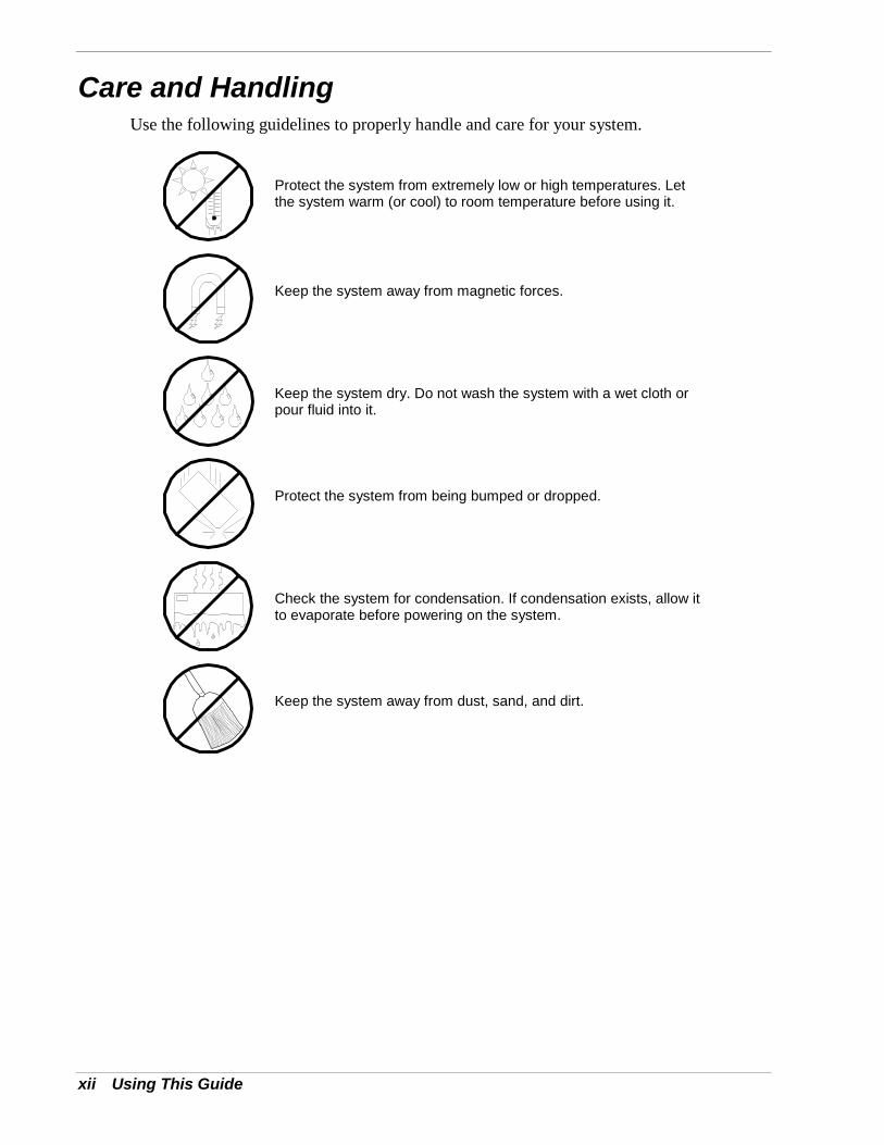
Care and HandlingUse the following guidelines to properly handle and care for your system.
Protect the system from extremely low or high temperatures. Letthe system warm (or cool) to room temperature before using it.
Keep the system away from magnetic forces.
Keep the system dry. Do not wash the system with a wet cloth orpour fluid into it.
Protect the system from being bumped or dropped.
Check the system for condensation. If condensation exists, allow itto evaporate before powering on the system.
Keep the system away from dust, sand, and dirt.
1System Overview
! Overview! System Chassis! Power Supply! Peripheral Bays! System Board Features! AC Link Mode! Remote Power-On (Wake ON LAN) Function! Degradation Feature! System Security
1-2 System Overview
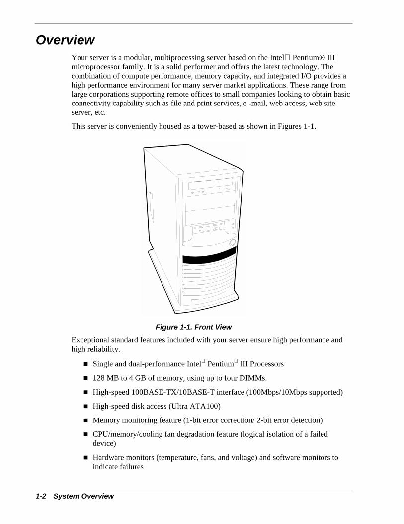
OverviewYour server is a modular, multiprocessing server based on the Intel Pentium® IIImicroprocessor family. It is a solid performer and offers the latest technology. Thecombination of compute performance, memory capacity, and integrated I/O provides ahigh performance environment for many server market applications. These range fromlarge corporations supporting remote offices to small companies looking to obtain basicconnectivity capability such as file and print services, e -mail, web access, web siteserver, etc.
This server is conveniently housed as a tower-based as shown in Figures 1-1.
Figure 1-1. Front ViewExceptional standard features included with your server ensure high performance andhigh reliability.
! Single and dual-performance Intel Pentium III Processors
! 128 MB to 4 GB of memory, using up to four DIMMs.
! High-speed 100BASE-TX/10BASE-T interface (100Mbps/10Mbps supported)
! High-speed disk access (Ultra ATA100)
! Memory monitoring feature (1-bit error correction/ 2-bit error detection)
! CPU/memory/cooling fan degradation feature (logical isolation of a faileddevice)
! Hardware monitors (temperature, fans, and voltage) and software monitors toindicate failures
System Overview 1-3
! Error notification
! BIOS password feature
! Security feature (security lock).
As application requirements increase, you can expand your server with an additionalprocessor, additional memory, add-in boards and peripheral devices: tape devices,CD-ROM, diskette drives and hard disk drives. Also included with your system is:
! Six PCI expansion slots for add-in boards including four 33MHz PCI bus slotsand two 66MHz PCI bus slots
! Embedded PC-compatible support (serial, parallel, mouse, keyboard, diskette,USB, LAN, and video)
! ATI RAGE XL (VRAM) integrated onboard video controller with 8 MB ofvideo memory
! Dual Channel enhanced IDE controller
! Three 5 ¼-inch removable media expansion bays with a 48-speed CD-ROMdrive installed in one bay
! One 3 ½-inch half-height bay with a diskette drive installed
! Integrated dual Universal Serial Bus (USB) ports
! One standard auto-sensing 264 watt power supply
! Hard disk expansion bays supporting two IDE hard disk drives.
1-4 System Overview
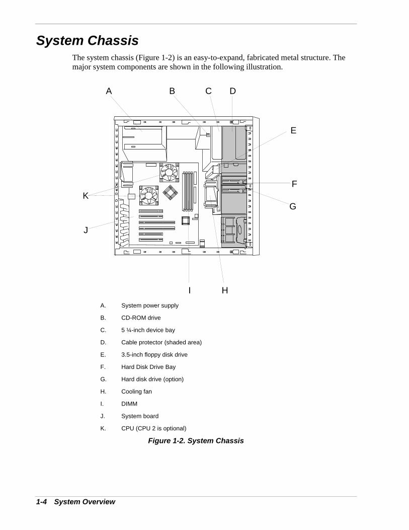
System ChassisThe system chassis (Figure 1-2) is an easy-to-expand, fabricated metal structure. Themajor system components are shown in the following illustration.
A B C D
E
F
G
HI
J
K
A. System power supply
B. CD-ROM drive
C. 5 ¼-inch device bay
D. Cable protector (shaded area)
E. 3.5-inch floppy disk drive
F. Hard Disk Drive Bay
G. Hard disk drive (option)
H. Cooling fan
I. DIMM
J. System board
K. CPU (CPU 2 is optional)
Figure 1-2. System Chassis
System Overview 1-5
Power SupplyThe 264-watt auto-voltage-sensing power supply provides system power. The powersupply operates at 115 or 230 VAC at an operating frequency of 50/60 Hz. It isdesigned to comply with existing emission standards and provides sufficient power fora fully loaded system configuration.
Peripheral BaysThe system supports a variety of standard PC AT-compatible peripheral devices. Thechassis includes these peripheral bays:
! A 3.5-inch front panel bay for mounting the standard 3.5" diskette drive(supports 720 KB and 1.44 MB diskette media)
! Three 5.25-inch removable media front panel bays for mounting half-height5.25-inch peripheral devices: standard CD-ROM drive and optional tape drives,etc.
! A 3.5-inch hard disk drive bay for installing up to two hard disk drives.
1-6 System Overview
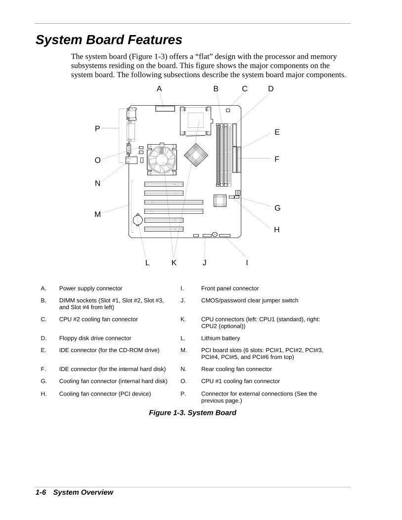
System Board FeaturesThe system board (Figure 1-3) offers a “flat” design with the processor and memorysubsystems residing on the board. This figure shows the major components on thesystem board. The following subsections describe the system board major components.
A B C D
E
F
G
H
IJKL
M
N
O
P
A. Power supply connector I. Front panel connector
B. DIMM sockets (Slot #1, Slot #2, Slot #3,and Slot #4 from left)
J. CMOS/password clear jumper switch
C. CPU #2 cooling fan connector K. CPU connectors (left: CPU1 (standard), right:CPU2 (optional))
D. Floppy disk drive connector L. Lithium battery
E. IDE connector (for the CD-ROM drive) M. PCI board slots (6 slots: PCI#1, PCI#2, PCI#3,PCI#4, PCI#5, and PCI#6 from top)
F. IDE connector (for the internal hard disk) N. Rear cooling fan connector
G. Cooling fan connector (internal hard disk) O. CPU #1 cooling fan connector
H. Cooling fan connector (PCI device) P. Connector for external connections (See theprevious page.)
Figure 1-3. System Board
System Overview 1-7
Pentium III ProcessorDepending on system configuration, your server includes one or two Pentium IIIprocessors. Each Pentium III plugs into a ZIF (Zero Insertion Force) socket on thesystem board. The processor includes a numeric coprocessor, a 256KB L2 cache andoperates at a bus speed of 133MHz. The optional second Pentium III processorenhances performance and enables symmetric multiprocessing (SMP).
System MemoryThe system board contains four 168-pin DIMM sockets. Memory is partitioned as fourbanks of SDRAM registered DIMMs (PC133 compatible), each providing 72 bits ofnoninterleaved memory (64-bit main memory plus ECC). Your system may includefrom 128MB to 4GB of memory, using up to four DIMMs.
System memory begins at address 0 and is continuous (flat addressing) up to themaximum amount of DRAM installed (exception: system memory is noncontiguous inthe ranges defined as memory holes using configuration registers). The systemsupports both base (conventional) and extended memory.
Real-Time Clock/CalendarThe real-time clock provides system clock/calendar information stored in a non-volatilememory (NVRAM). The real-time clock battery provides power backup for the real-time clock.
BIOSA BIOS and Setup Utility are located in the Flash EPROM on the system board andinclude support for system setup and Legacy device configuration. A number ofsecurity, reliability, and management features also have been incorporated to meet vitalserver needs.
1-8 System Overview
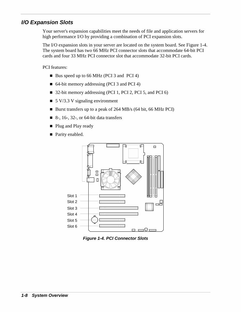
I/O Expansion SlotsYour server's expansion capabilities meet the needs of file and application servers forhigh performance I/O by providing a combination of PCI expansion slots.
The I/O expansion slots in your server are located on the system board. See Figure 1-4.The system board has two 66 MHz PCI connector slots that accommodate 64-bit PCIcards and four 33 MHz PCI connector slot that accommodate 32-bit PCI cards.
PCI features:
! Bus speed up to 66 MHz (PCI 3 and PCI 4)
! 64-bit memory addressing (PCI 3 and PCI 4)
! 32-bit memory addressing (PCI 1, PCI 2, PCI 5, and PCI 6)
! 5 V/3.3 V signaling environment
! Burst transfers up to a peak of 264 MB/s (64 bit, 66 MHz PCI)
! 8-, 16-, 32-, or 64-bit data transfers
! Plug and Play ready
! Parity enabled.
Slot 1Slot 2Slot 3Slot 4Slot 5Slot 6
Figure 1-4. PCI Connector Slots
System Overview 1-9
IDE ControllerThe system includes a dual channel enhanced IDE 32 bit interface controller forintelligent disk drives with disk controller electronics onboard. The IDE controllerprovides support for the internally mounted CD-ROM.
The device controls:
! PIO and DMA transfer modes
! Mode 4 timings
! Transfer rates up to 33 MB/s
! Buffering for PCI/IDE burst transfers
Keyboard and Mouse ControllerThe keyboard and mouse controller is PS/2 compatible.
Network ControllerThe system board includes a 10BASE-T/100BASE-TX network controller based on theIntel 82559 Fast Ethernet PCI Bus Controller. As a PCI bus master, the controller canburst data at up to 132 MB/sec. The controller contains two receive and transmit FIFObuffers that prevent data overruns or underruns while waiting for access to the PCI bus.The controller has the following:
! 32-bit PCI bus master interface (direct drive of bus), compatible with PCI BusSpecification, Revision 2.1
! Chained memory structure with improved dynamic transmit chaining forenhanced performance
! Programmable transmit threshold for improved bus utilization
! Early receive interrupt for concurrent processing of receive data
! On-chip counters for network management
! Autodetect and autoswitching for 10 or 100 Mbps network speeds
! Support for both 10 Mbps and 100 Mbps networks, capable of full or halfduplex, with back-to-back transmit at 100 Mbps.
! Support for Wake On LAN.
Video ControllerThe system has an integrated ATI RAGE XL 64 bit high-performance SVGAsubsystem that supports the following:
! BIOS compatibility with VGA, EGA, CGA, Hercules Graphics, and MDA
! 8 MB of 10ns onboard Synchronous Graphics Memory (SGRAM)
1-10 System Overview
! Pixel resolutions up to 1280 X 1024
! Analog VGA monitors (single and multiple frequency, interlaced and non-interlaced) with a maximum vertical retrace non-interlaced frequency of100 Hz.
Peripheral ControllerThe advanced integrated peripheral controller supports two serial ports, two universalserial ports, one parallel port, diskette drive, PS/2-compatible keyboard and mouse, andintegrated Real Time Clock (RTC). The system provides the connector interface foreach port.
Serial Ports
Both serial ports are relocatable. Each serial port can be set to one of four differentaddresses and can be enabled separately. When disabled, serial port interrupts areavailable to add-in boards.
Parallel Port
One IEEE 1284-compatible 25-pin bi-directional EPP (supporting levels 1.7 and 1.9)parallel port is provided. BIOS programming enables the parallel port and determinesthe port address and interrupt. ECP mode is supported with 2 possible DMA channels.When disabled, the interrupt is available to add-in boards.
External Device ConnectorsThe external I/O connectors provide support for a PS/2 compatible mouse and akeyboard, for a SVGA monitor, 2 serial port connectors, a parallel port connector, LANport, and two USB connections.
ACPIThe Advanced Configuration and Power Interface (ACPI) aware operating system canplace the system into a state where the hard drives spin down, the system fans stop, andall processing is halted. However, in this state the power supply is still on and theprocessors are still dissipating some power such that the power supply fan andprocessor fans are still running.
Note: ACPI requires an operating system that supports itsfeature.
This server system BIOS supports sleep states s0, s1, s4, and s5. However, with futureversions of Microsoft Windows 9X that support ACPI, the system BIOS only supportssleep states s0, s1, and s5. With future versions of Microsoft Windows NT that supportACPI, the system BIOS will only support sleep states s0, s1, s4, and s5.
System Overview 1-11
! CAUTIONOnly when the AC power is disconnected is the system completelyoff.
The sleep states are defined as follows:
! s0: Normal running state.
! s1: Processor sleep state.No context will be lost in this state and the processor caches will maintaincoherency.
! s4: Hibernate or Save to Disk.The memory and machine state are saved to disk. Pressing the power button orother wakeup event restores the system state from the disk and resumes normaloperation. This assumes that no hardware changes have been made to the systemwhile it was off.
! s5: Soft off.Only the RTC section of the chipset and the BMC are running in this state.
AC Link ModeThe AC link mode allows the system to monitor its AC input power so that when theAC input power is lost and then restored the system will return itself to one of three pre-selected settings, listed as follows:
! Power On
! Last State (Factory Default Setting)
! Stay Off.
The AC link mode settings can be changed by running the BIOS Setup Utility (F2).Refer to Chapter 3 "Configuring Your System."
1-12 System Overview
Remote Power-On (Wake ON LAN) FunctionThe remote power-on function turns on the system power by way of a network ormodem. If the system power is set to OFF, it can be turned on remotely by sending aspecific packet from the main computer to the remote system. This feature can beenabled or disabled using the BIOS Setup Utility. See Chapter 3.
Note: This feature must be supported by your operating system.
Degradation FeatureThe degradation feature automatically isolates a failed DIMM, processor, or cooling fanto assure continuous operation of the server. The failed DIMM, processor, or coolingfan is detected and isolated during POST (Power On Self-Test, self-diagnosis programafter power on). POST runs automatically during system startup.
Failed DIMMs, processors, and cooling fan may be identified by a POST error codedisplay, or by viewing NEC ESMPRO error messages.
System SecuritySecurity with Mechanical Locks and Monitoring
To help prevent unauthorized entry or use of the system, the system includes a fullylockable side panel.
Software Locks via the System Setup UtilityThe BIOS Setup Utility provides a number of security features to prevent unauthorizedor accidental access to the system. Once the security measures are enabled, access to thesystem is allowed only after the user enters the correct password(s). For example:
! Enable the keyboard lockout timer so that the server requires a password toreactivate the keyboard and mouse after a specified time-out period 2 to120minutes.
! Set and enable an administrative password.
! Set and enable a user password
! Set secure mode to prevent keyboard or mouse input and to prevent use of thefront panel reset and power switches.
! Activate a hot-key combination to enter secure mode quickly.
! Disable writing to the diskette drive when secure mode is set.
2Setting Up the System
! Overview! Selecting a Site! Unpacking the System! Getting Familiar with the System! Making Connections! Connecting the Power Cord! Powering On Your System
2-2 Setting Up the System
OverviewThis chapter describes how to select a site, make cable connections, and poweron the system. Information on front and rear panel features, switches and LEDsare also included in this chapter.
Selecting a SiteThe system operates reliably in a typical office environment.Choose a site that is:
! Near grounded, three-pronged power outlets.
Note: For the United States and Canada, this means aNEMA 5-15R outlets for 100-120 VAC or NEMA 6-15Routlets for 200-240 VAC. For other international sites, thismeans three-pronged power outlets applicable for theelectrical code of the region.
! WARNINGBe sure the power service connection is through a properlygrounded outlet.
! Clean, dust-free, and well ventilated. Front and rear ventilating openingskept free of obstructions. Away from sources of heat, vibration orphysical shock.
! Isolated from strong electromagnetic fields and electrical noise producedby electrical devices (such as air conditioners, large fans, large electricmotors, radio and TV transmitters, and high-frequency security devices)
! Spacious enough to provide at least five inches (13 centimeters) behindthe system and three inches (eight centimeters) on each side of the systemfor proper cooling, airflow, and cable clearance.
! Easily accessible for system maintenance and installation of systemupgrades.
Setting Up the System 2-3
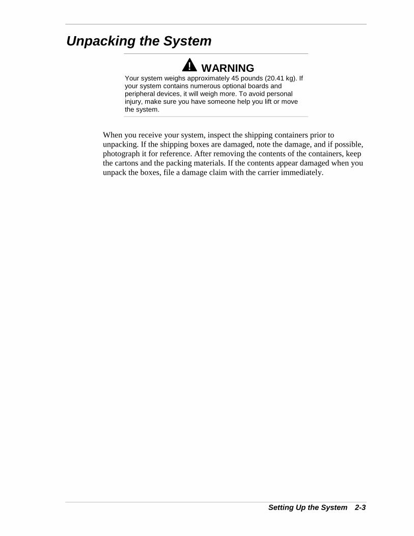
Unpacking the System
! WARNINGYour system weighs approximately 45 pounds (20.41 kg). Ifyour system contains numerous optional boards andperipheral devices, it will weigh more. To avoid personalinjury, make sure you have someone help you lift or movethe system.
When you receive your system, inspect the shipping containers prior tounpacking. If the shipping boxes are damaged, note the damage, and if possible,photograph it for reference. After removing the contents of the containers, keepthe cartons and the packing materials. If the contents appear damaged when youunpack the boxes, file a damage claim with the carrier immediately.
2-4 Setting Up the System
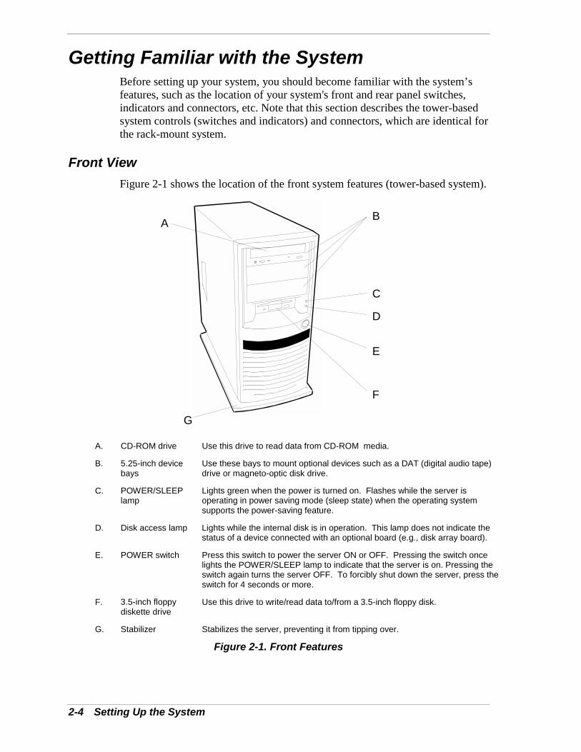
Getting Familiar with the SystemBefore setting up your system, you should become familiar with the system’sfeatures, such as the location of your system's front and rear panel switches,indicators and connectors, etc. Note that this section describes the tower-basedsystem controls (switches and indicators) and connectors, which are identical forthe rack-mount system.
Front ViewFigure 2-1 shows the location of the front system features (tower-based system).
A B
C
D
E
F
G
A. CD-ROM drive Use this drive to read data from CD-ROM media.
B. 5.25-inch devicebays
Use these bays to mount optional devices such as a DAT (digital audio tape)drive or magneto-optic disk drive.
C. POWER/SLEEPlamp
Lights green when the power is turned on. Flashes while the server isoperating in power saving mode (sleep state) when the operating systemsupports the power-saving feature.
D. Disk access lamp Lights while the internal disk is in operation. This lamp does not indicate thestatus of a device connected with an optional board (e.g., disk array board).
E. POWER switch Press this switch to power the server ON or OFF. Pressing the switch oncelights the POWER/SLEEP lamp to indicate that the server is on. Pressing theswitch again turns the server OFF. To forcibly shut down the server, press theswitch for 4 seconds or more.
F. 3.5-inch floppydiskette drive
Use this drive to write/read data to/from a 3.5-inch floppy disk.
G. Stabilizer Stabilizes the server, preventing it from tipping over.
Figure 2-1. Front Features
Setting Up the System 2-5
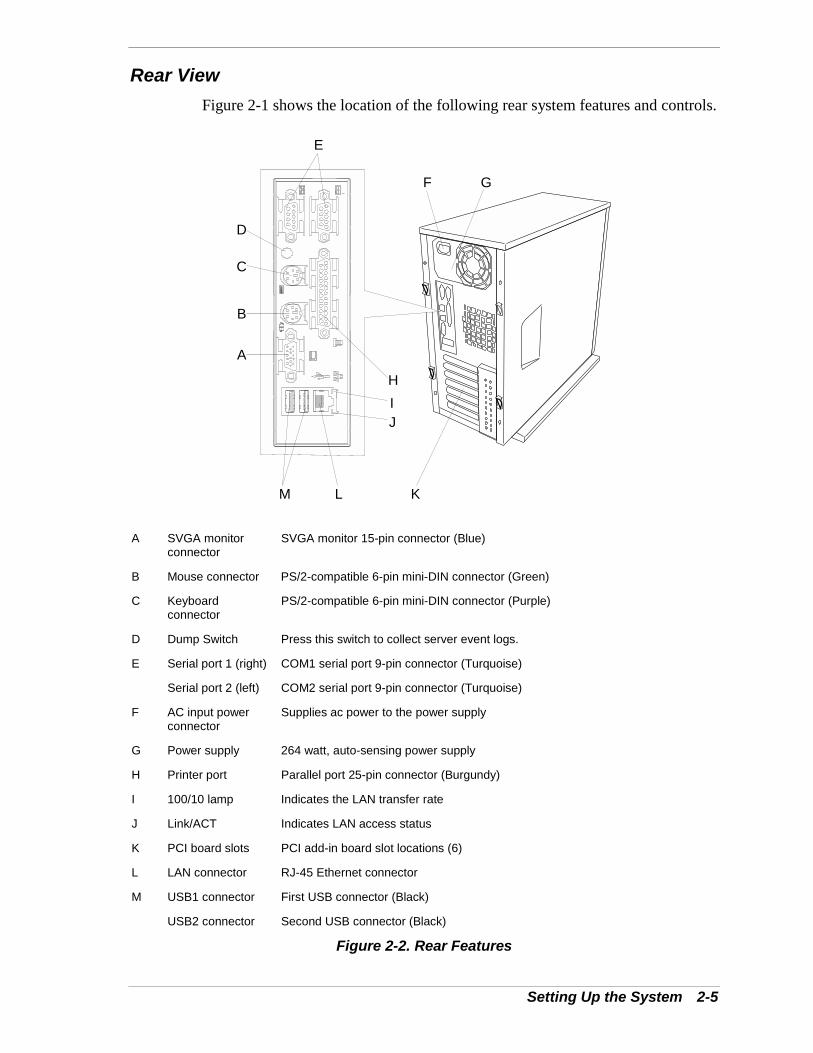
Rear ViewFigure 2-1 shows the location of the following rear system features and controls.
A
B
C
D
E
F G
HIJ
KLM
A SVGA monitorconnector
SVGA monitor 15-pin connector (Blue)
B Mouse connector PS/2-compatible 6-pin mini-DIN connector (Green)
C Keyboardconnector
PS/2-compatible 6-pin mini-DIN connector (Purple)
D Dump Switch Press this switch to collect server event logs.
E Serial port 1 (right)
Serial port 2 (left)
COM1 serial port 9-pin connector (Turquoise)
COM2 serial port 9-pin connector (Turquoise)
F AC input powerconnector
Supplies ac power to the power supply
G Power supply 264 watt, auto-sensing power supply
H Printer port Parallel port 25-pin connector (Burgundy)
I 100/10 lamp Indicates the LAN transfer rate
J Link/ACT Indicates LAN access status
K PCI board slots PCI add-in board slot locations (6)
L LAN connector RJ-45 Ethernet connector
M USB1 connector
USB2 connector
First USB connector (Black)
Second USB connector (Black)
Figure 2-2. Rear Features
2-6 Setting Up the System
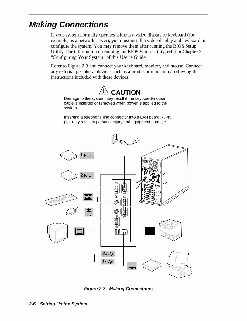
Making ConnectionsIf your system normally operates without a video display or keyboard (forexample, as a network server), you must install a video display and keyboard toconfigure the system. You may remove them after running the BIOS SetupUtility. For information on running the BIOS Setup Utility, refer to Chapter 3"Configuring Your System" of this User’s Guide.
Refer to Figure 2-3 and connect your keyboard, monitor, and mouse. Connectany external peripheral devices such as a printer or modem by following theinstructions included with these devices.
! CAUTIONDamage to the system may result if the keyboard/mousecable is inserted or removed when power is applied to thesystem.
Inserting a telephone line connector into a LAN board RJ-45port may result in personal injury and equipment damage.
2
1
2
1
Figure 2-3. Making Connections
Setting Up the System 2-7
Connecting the Power CordPlug the female end of the AC power cord into the input receptacle on the rearof the power supply cage. Plug the male end of the power cord into NEMA 5-15R outlet for 100-120 VAC or NEMA 6-15R outlet for 200-240 VAC.
If the power cord supplied with the system is not compatible with the AC walloutlet in your region, obtain a suitable power cord that meets the followingcriteria.
! The power cord must be rated for the available AC voltage and have acurrent rating that is at least 125% of the current rating of the system.
! The power cord connector that plugs into the wall outlet must beterminated in a grounding-type male plug designed for use in your region.It must have certification marks showing certification by an agencyacceptable in your region.
! The power cord connector that plugs into the system must be an IEC-type CEE-22 female connector.
! The power cord must be less than 1.8 meters (6.0 feet) long.
When connecting the power cord to a power control unit such as an UPS,confirm that the power control unit is powered off. Connecting the power cordwhile power is supplied to the power control unit may cause a failure.
! WARNINGYour system shipped with a power cord for the powersupply. Do not attempt to modify or use the supplied ACpower cord if it is not the exact type required.
2-8 Setting Up the System
Powering On Your SystemPower on your system as follows.
1. Make sure all external devices, such as a video display, keyboard, andmouse have been connected, and the power cords are connected.
2. Power on the video display and any other external devices.
3. Press the push-button power on/off switch on the front panel. Verify that thesystem power-on LED is lit. See Figure 2-1 for the location of the power-onLED.
Note: The server management logic on your systemboard monitors and logs system voltage changes. Whenpowering up or down your system you may experience a1–5 second delay from the time you press the push-buttonpower on/off switch on the front panel and your systempowering down. This is normal system operation and isrequired by the server management logic.
After a few seconds your system begins the internal Power-On Self Tests(POST). POST automatically checks the system board, CPU module, memory,keyboard, and most installed peripheral devices.
! CAUTIONAlways allow POST to complete before powering down yoursystem.
If you have problems powering on your system, refer to Problem Solving inChapter 5 of this User’s Guide.
After you have successfully powered on your system, insert theEXPRESSBUILDER CD-ROM into the CD-ROM device, reboot the system andfollow the screen prompts to run EXPRESSBUILDER.
3Configuring Your System
! Configuring Your System! BIOS Setup Utility! Configuring System Board Jumpers
3-2 Configuring Your System
Configuring Your SystemConfiguration and setup utilities are used to change your system configuration.You can configure your system, as well as option boards you may add to yoursystem, using the BIOS Setup Utility. Several unique system parameters areconfigured using the BIOS Setup, which is stored in the system FLASHmemory.
If your system has been factory configured, the BIOS Setup does not need to berun unless you want to change the password or security features, add certaintypes of option boards or devices, or upgrade your system board.
This chapter also provides information on several system configurationparameters that are set by jumpers on the system board. However, theseparameters do not usually require change.
Use the EXPRESSBUILDER CD-ROM to create the device driver diskettes.
Configuring Your System 3-3
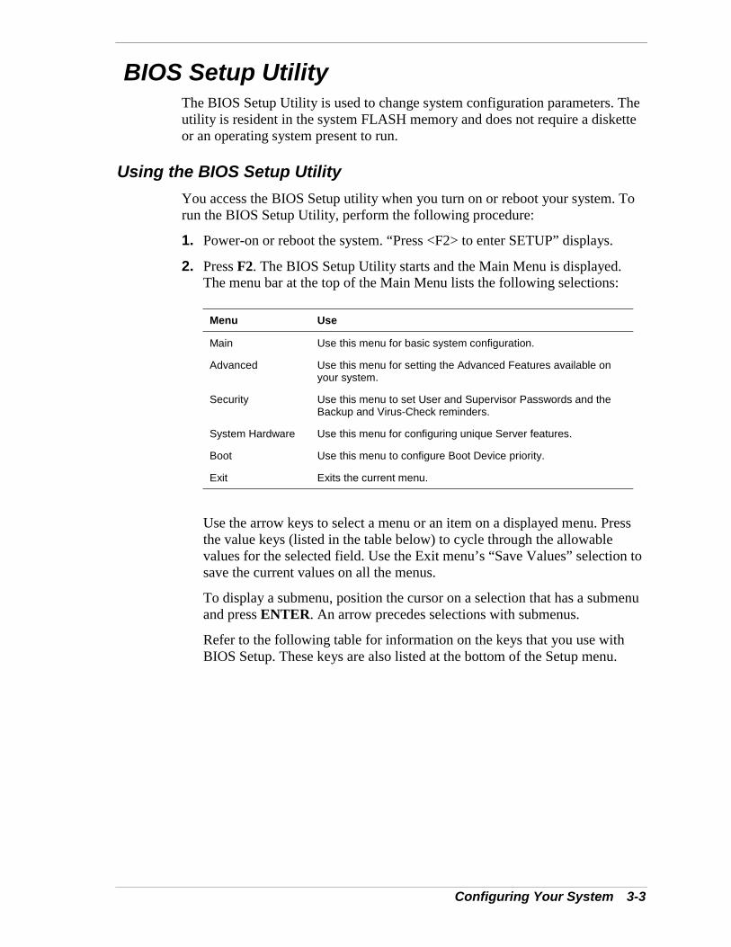
BIOS Setup UtilityThe BIOS Setup Utility is used to change system configuration parameters. Theutility is resident in the system FLASH memory and does not require a disketteor an operating system present to run.
Using the BIOS Setup UtilityYou access the BIOS Setup utility when you turn on or reboot your system. Torun the BIOS Setup Utility, perform the following procedure:
1. Power-on or reboot the system. “Press <F2> to enter SETUP” displays.
2. Press F2. The BIOS Setup Utility starts and the Main Menu is displayed.The menu bar at the top of the Main Menu lists the following selections:
Menu Use
Main Use this menu for basic system configuration.
Advanced Use this menu for setting the Advanced Features available onyour system.
Security Use this menu to set User and Supervisor Passwords and theBackup and Virus-Check reminders.
System Hardware Use this menu for configuring unique Server features.
Boot Use this menu to configure Boot Device priority.
Exit Exits the current menu.
Use the arrow keys to select a menu or an item on a displayed menu. Pressthe value keys (listed in the table below) to cycle through the allowablevalues for the selected field. Use the Exit menu’s “Save Values” selection tosave the current values on all the menus.
To display a submenu, position the cursor on a selection that has a submenuand press ENTER. An arrow precedes selections with submenus.
Refer to the following table for information on the keys that you use withBIOS Setup. These keys are also listed at the bottom of the Setup menu.
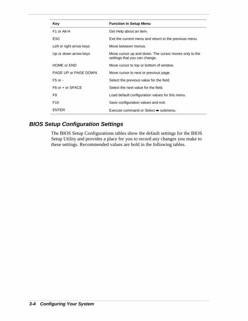
3-4 Configuring Your System
Key Function in Setup Menu
F1 or Alt-H Get Help about an item.
ESC Exit the current menu and return to the previous menu.
Left or right arrow keys Move between menus.
Up or down arrow keys Move cursor up and down. The cursor moves only to thesettings that you can change.
HOME or END Move cursor to top or bottom of window.
PAGE UP or PAGE DOWN Move cursor to next or previous page.
F5 or - Select the previous value for the field.
F6 or + or SPACE Select the next value for the field.
F9 Load default configuration values for this menu.
F10 Save configuration values and exit.
ENTER Execute command or Select ➨ submenu.
BIOS Setup Configuration SettingsThe BIOS Setup Configurations tables show the default settings for the BIOSSetup Utility and provides a place for you to record any changes you make tothese settings. Recommended values are bold in the following tables.
Configuring Your System 3-5
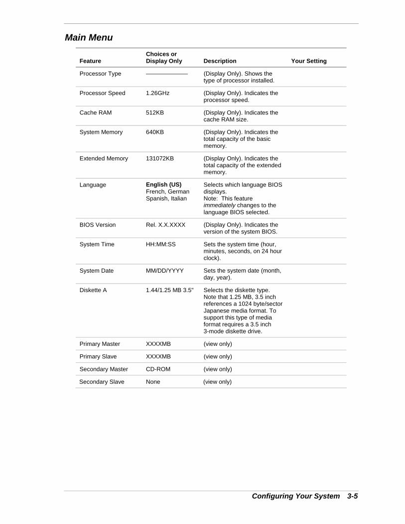
Main Menu
FeatureChoices orDisplay Only Description Your Setting
Processor Type ——————— (Display Only). Shows thetype of processor installed.
Processor Speed 1.26GHz (Display Only). Indicates theprocessor speed.
Cache RAM 512KB (Display Only). Indicates thecache RAM size.
System Memory 640KB (Display Only). Indicates thetotal capacity of the basicmemory.
Extended Memory 131072KB (Display Only). Indicates thetotal capacity of the extendedmemory.
Language English (US)French, GermanSpanish, Italian
Selects which language BIOSdisplays.Note: This featureimmediately changes to thelanguage BIOS selected.
BIOS Version Rel. X.X.XXXX (Display Only). Indicates theversion of the system BIOS.
System Time HH:MM:SS Sets the system time (hour,minutes, seconds, on 24 hourclock).
System Date MM/DD/YYYY Sets the system date (month,day, year).
Diskette A 1.44/1.25 MB 3.5" Selects the diskette type.Note that 1.25 MB, 3.5 inchreferences a 1024 byte/sectorJapanese media format. Tosupport this type of mediaformat requires a 3.5 inch3-mode diskette drive.
Primary Master XXXXMB (view only)
Primary Slave XXXXMB (view only)
Secondary Master CD-ROM (view only)
Secondary Slave None (view only)
3-6 Configuring Your System
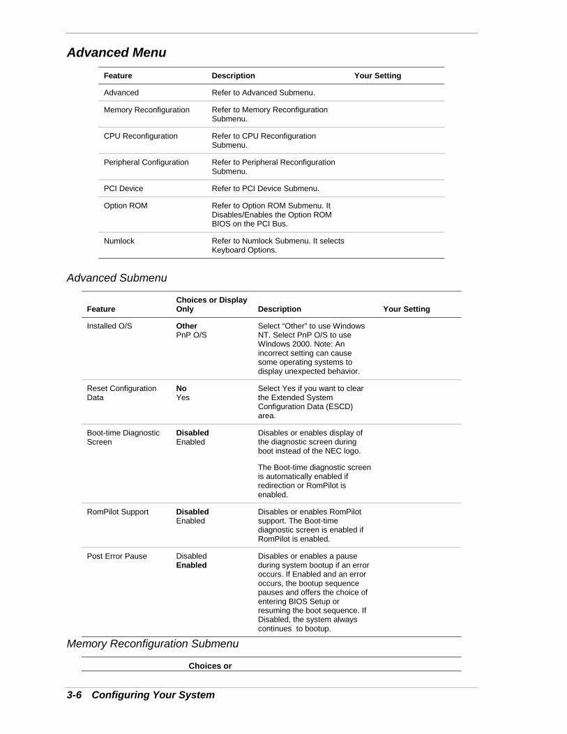
Advanced MenuFeature Description Your Setting
Advanced Refer to Advanced Submenu.
Memory Reconfiguration Refer to Memory ReconfigurationSubmenu.
CPU Reconfiguration Refer to CPU ReconfigurationSubmenu.
Peripheral Configuration Refer to Peripheral ReconfigurationSubmenu.
PCI Device Refer to PCI Device Submenu.
Option ROM Refer to Option ROM Submenu. ItDisables/Enables the Option ROMBIOS on the PCI Bus.
Numlock Refer to Numlock Submenu. It selectsKeyboard Options.
Advanced Submenu
FeatureChoices or DisplayOnly Description Your Setting
Installed O/S OtherPnP O/S
Select “Other” to use WindowsNT. Select PnP O/S to useWindows 2000. Note: Anincorrect setting can causesome operating systems todisplay unexpected behavior.
Reset ConfigurationData
NoYes
Select Yes if you want to clearthe Extended SystemConfiguration Data (ESCD)area.
Boot-time DiagnosticScreen
DisabledEnabled
Disables or enables display ofthe diagnostic screen duringboot instead of the NEC logo.
The Boot-time diagnostic screenis automatically enabled ifredirection or RomPilot isenabled.
RomPilot Support DisabledEnabled
Disables or enables RomPilotsupport. The Boot-timediagnostic screen is enabled ifRomPilot is enabled.
Post Error Pause DisabledEnabled
Disables or enables a pauseduring system bootup if an erroroccurs. If Enabled and an erroroccurs, the bootup sequencepauses and offers the choice ofentering BIOS Setup orresuming the boot sequence. IfDisabled, the system alwayscontinues to bootup.
Memory Reconfiguration Submenu
Choices or
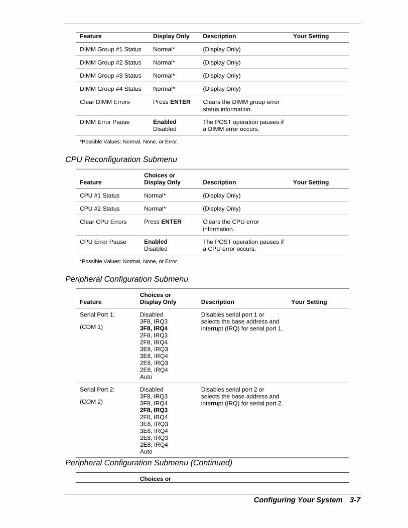
Configuring Your System 3-7
Feature Display Only Description Your Setting
DIMM Group #1 Status Normal* (Display Only)
DIMM Group #2 Status Normal* (Display Only)
DIMM Group #3 Status Normal* (Display Only)
DIMM Group #4 Status Normal* (Display Only)
Clear DIMM Errors Press ENTER Clears the DIMM group errorstatus information.
DIMM Error Pause EnabledDisabled
The POST operation pauses ifa DIMM error occurs.
*Possible Values: Normal, None, or Error.
CPU Reconfiguration Submenu
FeatureChoices orDisplay Only Description Your Setting
CPU #1 Status Normal* (Display Only)
CPU #2 Status Normal* (Display Only)
Clear CPU Errors Press ENTER Clears the CPU errorinformation.
CPU Error Pause EnabledDisabled
The POST operation pauses ifa CPU error occurs.
*Possible Values: Normal, None, or Error.
Peripheral Configuration Submenu
FeatureChoices orDisplay Only Description Your Setting
Serial Port 1:
(COM 1)
Disabled3F8, IRQ33F8, IRQ42F8, IRQ32F8, IRQ43E8, IRQ33E8, IRQ42E8, IRQ32E8, IRQ4Auto
Disables serial port 1 orselects the base address andinterrupt (IRQ) for serial port 1.
Serial Port 2:
(COM 2)
Disabled3F8, IRQ33F8, IRQ42F8, IRQ32F8, IRQ43E8, IRQ33E8, IRQ42E8, IRQ32E8, IRQ4Auto
Disables serial port 2 orselects the base address andinterrupt (IRQ) for serial port 2.
Peripheral Configuration Submenu (Continued)
Choices or
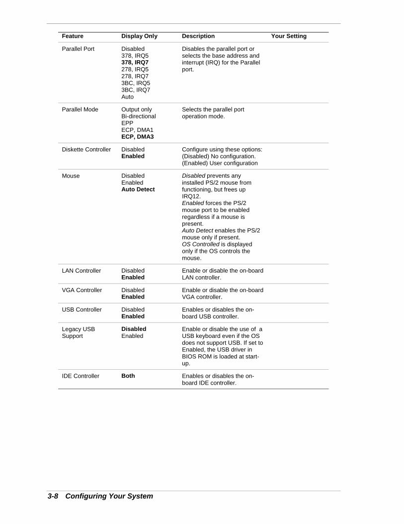
3-8 Configuring Your System
Feature Display Only Description Your Setting
Parallel Port Disabled378, IRQ5378, IRQ7278, IRQ5278, IRQ73BC, IRQ53BC, IRQ7Auto
Disables the parallel port orselects the base address andinterrupt (IRQ) for the Parallelport.
Parallel Mode Output onlyBi-directionalEPPECP, DMA1ECP, DMA3
Selects the parallel portoperation mode.
Diskette Controller DisabledEnabled
Configure using these options:(Disabled) No configuration.(Enabled) User configuration
Mouse DisabledEnabledAuto Detect
Disabled prevents anyinstalled PS/2 mouse fromfunctioning, but frees upIRQ12.Enabled forces the PS/2mouse port to be enabledregardless if a mouse ispresent.Auto Detect enables the PS/2mouse only if present.OS Controlled is displayedonly if the OS controls themouse.
LAN Controller DisabledEnabled
Enable or disable the on-boardLAN controller.
VGA Controller DisabledEnabled
Enable or disable the on-boardVGA controller.
USB Controller DisabledEnabled
Enables or disables the on-board USB controller.
Legacy USBSupport
DisabledEnabled
Enable or disable the use of aUSB keyboard even if the OSdoes not support USB. If set toEnabled, the USB driver inBIOS ROM is loaded at start-up.
IDE Controller Both Enables or disables the on-board IDE controller.
Configuring Your System 3-9
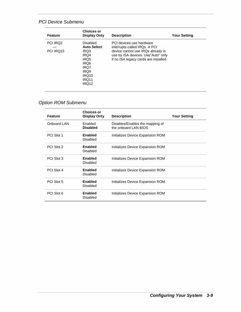
PCI Device Submenu
FeatureChoices orDisplay Only Description Your Setting
PCI IRQ2—
PCI IRQ15
DisabledAuto SelectIRQ3IRQ4IRQ5IRQ6IRQ7IRQ9IRQ10IRQ11IRQ12
PCI devices use hardwareinterrupts called IRQs. A PCIdevice cannot use IRQs already inuse by ISA devices. Use"Auto" onlyif no ISA legacy cards are installed.
Option ROM Submenu
FeatureChoices orDisplay Only Description Your Setting
Onboard LAN EnabledDisabled
Disables/Enables the mapping ofthe onboard LAN BIOS
PCI Slot 1 EnabledDisabled
Initializes Device Expansion ROM
PCI Slot 2 EnabledDisabled
Initializes Device Expansion ROM
PCI Slot 3 EnabledDisabled
Initializes Device Expansion ROM
PCI Slot 4 EnabledDisabled
Initializes Device Expansion ROM
PCI Slot 5 EnabledDisabled
Initializes Device Expansion ROM
PCI Slot 6 EnabledDisabled
Initializes Device Expansion ROM
3-10 Configuring Your System
Numlock Submenu
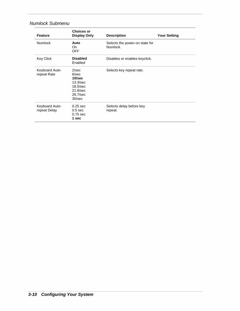
FeatureChoices orDisplay Only Description Your Setting
Numlock AutoOnOFF
Selects the power-on state forNumlock.
Key Click DisabledEnabled
Disables or enables keyclick.
Keyboard Auto-repeat Rate
2/sec6/sec10/sec13.3/sec18.5/sec21.8/sec26.7/sec30/sec
Selects key repeat rate.
Keyboard Auto-repeat Delay
0.25 sec0.5 sec0.75 sec1 sec
Selects delay before keyrepeat.
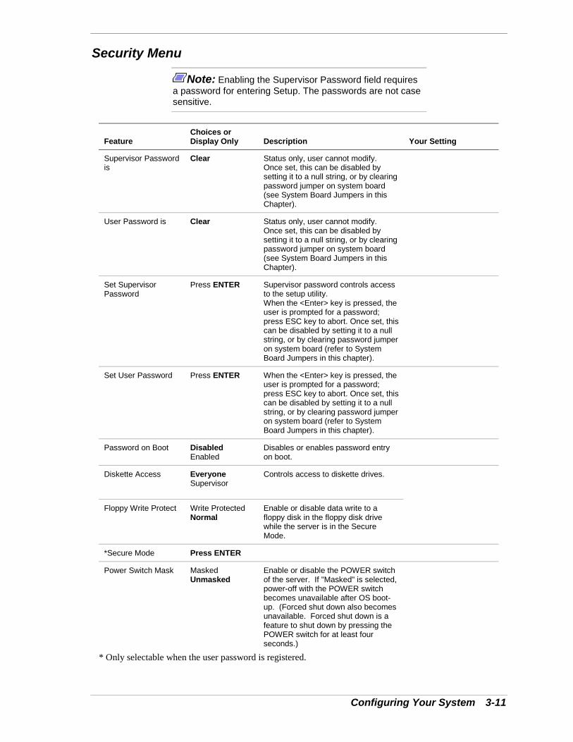
Configuring Your System 3-11
Security Menu
Note: Enabling the Supervisor Password field requiresa password for entering Setup. The passwords are not casesensitive.
FeatureChoices orDisplay Only Description Your Setting
Supervisor Passwordis
Clear Status only, user cannot modify.Once set, this can be disabled bysetting it to a null string, or by clearingpassword jumper on system board(see System Board Jumpers in thisChapter).
User Password is Clear Status only, user cannot modify.Once set, this can be disabled bysetting it to a null string, or by clearingpassword jumper on system board(see System Board Jumpers in thisChapter).
Set SupervisorPassword
Press ENTER Supervisor password controls accessto the setup utility.When the <Enter> key is pressed, theuser is prompted for a password;press ESC key to abort. Once set, thiscan be disabled by setting it to a nullstring, or by clearing password jumperon system board (refer to SystemBoard Jumpers in this chapter).
Set User Password Press ENTER When the <Enter> key is pressed, theuser is prompted for a password;press ESC key to abort. Once set, thiscan be disabled by setting it to a nullstring, or by clearing password jumperon system board (refer to SystemBoard Jumpers in this chapter).
Password on Boot DisabledEnabled
Disables or enables password entryon boot.
Diskette Access EveryoneSupervisor
Controls access to diskette drives.
Floppy Write Protect Write ProtectedNormal
Enable or disable data write to afloppy disk in the floppy disk drivewhile the server is in the SecureMode.
*Secure Mode Press ENTER
Power Switch Mask MaskedUnmasked
Enable or disable the POWER switchof the server. If "Masked" is selected,power-off with the POWER switchbecomes unavailable after OS boot-up. (Forced shut down also becomesunavailable. Forced shut down is afeature to shut down by pressing thePOWER switch for at least fourseconds.)
* Only selectable when the user password is registered.
3-12 Configuring Your System
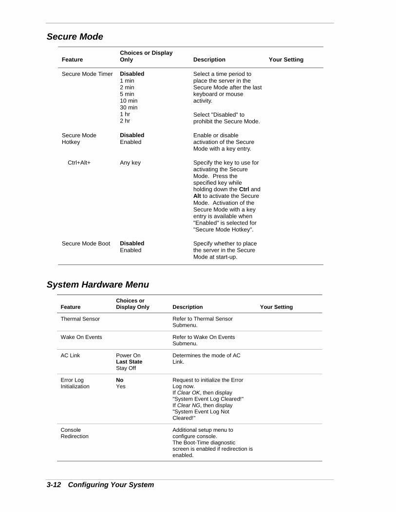
Secure Mode
FeatureChoices or DisplayOnly Description Your Setting
Secure Mode Timer Disabled1 min2 min5 min10 min30 min1 hr2 hr
Select a time period toplace the server in theSecure Mode after the lastkeyboard or mouseactivity.
Select "Disabled" toprohibit the Secure Mode.
Secure ModeHotkey
DisabledEnabled
Enable or disableactivation of the SecureMode with a key entry.
Ctrl+Alt+ Any key Specify the key to use foractivating the SecureMode. Press thespecified key whileholding down the Ctrl andAlt to activate the SecureMode. Activation of theSecure Mode with a keyentry is available when"Enabled" is selected for"Secure Mode Hotkey".
Secure Mode Boot DisabledEnabled
Specify whether to placethe server in the SecureMode at start-up.
System Hardware Menu
FeatureChoices orDisplay Only Description Your Setting
Thermal Sensor Refer to Thermal SensorSubmenu.
Wake On Events Refer to Wake On EventsSubmenu.
AC Link Power OnLast StateStay Off
Determines the mode of ACLink.
Error LogInitialization
NoYes
Request to initialize the ErrorLog now.If Clear OK, then display"System Event Log Cleared!"If Clear NG, then display"System Event Log NotCleared!"
ConsoleRedirection
Additional setup menu toconfigure console.The Boot-Time diagnosticscreen is enabled if redirection isenabled.
Configuring Your System 3-13
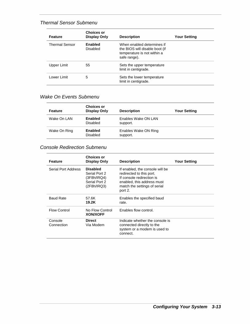
Thermal Sensor Submenu
FeatureChoices orDisplay Only Description Your Setting
Thermal Sensor EnabledDisabled
When enabled determines ifthe BIOS will disable boot (iftemperature is not within asafe range).
Upper Limit 55 Sets the upper temperaturelimit in centigrade.
Lower Limit 5 Sets the lower temperaturelimit in centigrade.
Wake On Events Submenu
FeatureChoices orDisplay Only Description Your Setting
Wake On LAN EnabledDisabled
Enables Wake ON LANsupport.
Wake On Ring EnabledDisabled
Enables Wake ON Ringsupport.
Console Redirection Submenu
FeatureChoices orDisplay Only Description Your Setting
Serial Port Address DisabledSerial Port 2(3F8h/IRQ4)Serial Port 2(2F8h/IRQ3)
If enabled, the console will beredirected to this port.If console redirection isenabled, this address mustmatch the settings of serialport 2.
Baud Rate 57.6K19.2K
Enables the specified baudrate.
Flow Control No Flow ControlXON/XOFF
Enables flow control.
ConsoleConnection
DirectVia Modem
Indicate whether the console isconnected directly to thesystem or a modem is used toconnect.
3-14 Configuring Your System
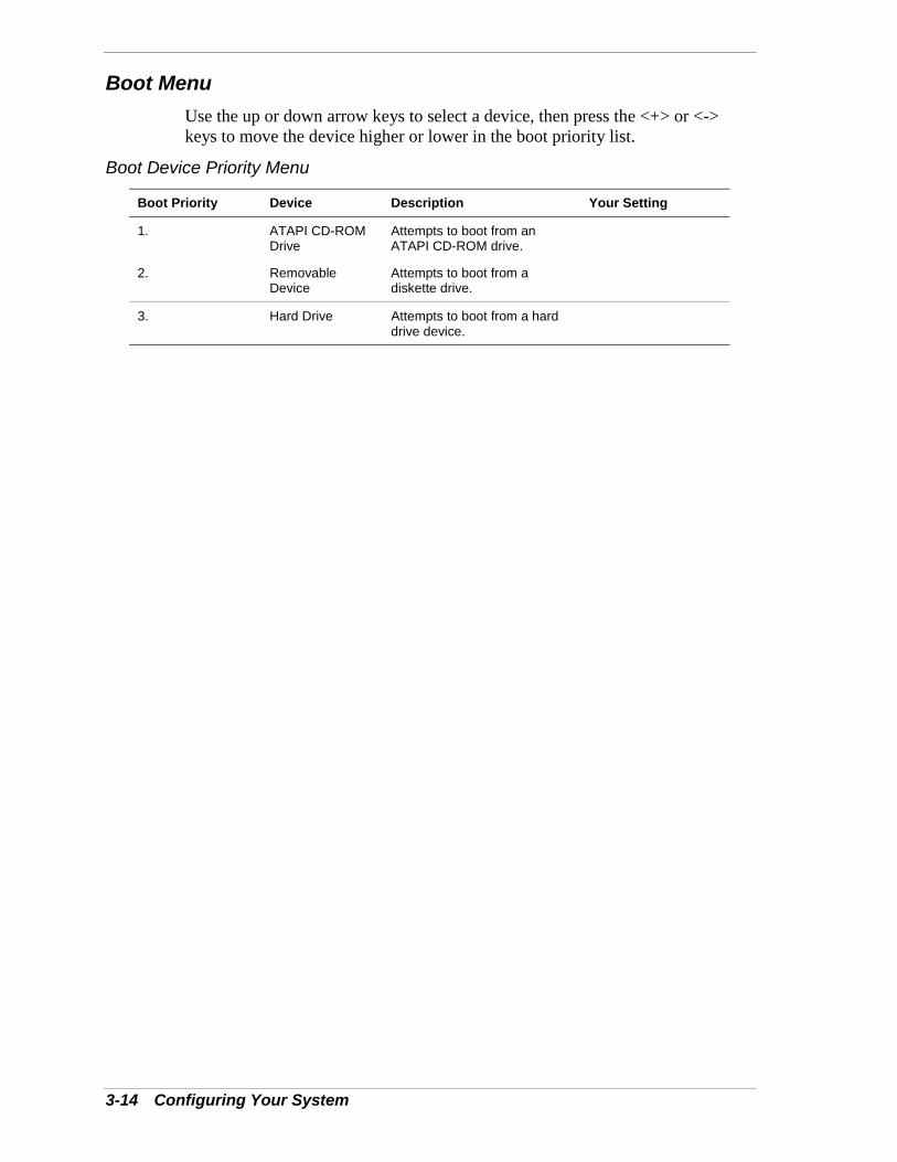
Boot MenuUse the up or down arrow keys to select a device, then press the <+> or <->keys to move the device higher or lower in the boot priority list.
Boot Device Priority Menu
Boot Priority Device Description Your Setting
1. ATAPI CD-ROMDrive
Attempts to boot from anATAPI CD-ROM drive.
2. RemovableDevice
Attempts to boot from adiskette drive.
3. Hard Drive Attempts to boot from a harddrive device.

Configuring Your System 3-15
Exit MenuYou can make the following selections on the Exit Menu. Select an optionusing the up or down arrow keys, then press <Enter> to execute the option.Pressing <Esc> does not exit this menu. You must select one of the items fromthe menu or menu bar to exit.
Exit Menu
Choices Description
Save Changes and Exit Exits System Setup after saving all changes to CMOS.
Exit Without Saving Changes Exits System Setup without saving setup data to CMOS.
Get Default Value Loads default values for all Setup items.
Load Previous Values Loads previous values of all Setup items.
Save Changes Writes all Setup item values to CMOS.
3-16 Configuring Your System
Configuring System Board JumpersBefore You Begin
Only a qualified technical person should perform the procedures in this section.
! CAUTIONElectrostatic discharge (ESD) can damage the systemboard. Modify the system board only at an ESD workstation.Otherwise, wear an antistatic wrist strap attached to chassisground.
The system board jumpers enable you to set specific operating parameters foryour system. A jumper is a small plastic-encased conductor (shorting plug) thatslips over two jumper pins.
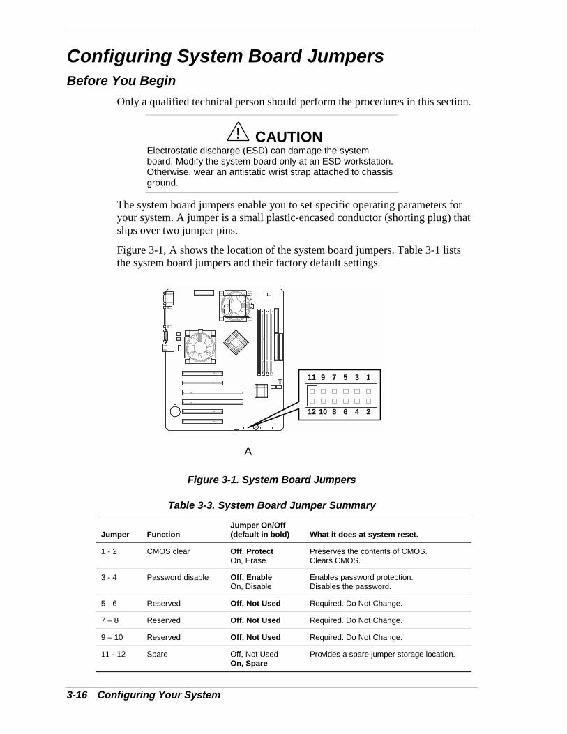
Figure 3-1, A shows the location of the system board jumpers. Table 3-1 liststhe system board jumpers and their factory default settings.
12 10 8 6 4 2
11 9 7 5 3 1
A
Figure 3-1. System Board Jumpers
Table 3-3. System Board Jumper Summary
Jumper FunctionJumper On/Off(default in bold) What it does at system reset.
1 - 2 CMOS clear Off, ProtectOn, Erase
Preserves the contents of CMOS.Clears CMOS.
3 - 4 Password disable Off, EnableOn, Disable
Enables password protection.Disables the password.
5 - 6 Reserved Off, Not Used Required. Do Not Change.
7 – 8 Reserved Off, Not Used Required. Do Not Change.
9 – 10 Reserved Off, Not Used Required. Do Not Change.
11 - 12 Spare Off, Not UsedOn, Spare
Provides a spare jumper storage location.

Configuring Your System 3-17
Moving System Board Jumpers
! CAUTIONBefore doing the procedures in this section, make sure thatyour system is powered off and unplug the AC power cordfrom the back of the chassis. Failure to disconnect powerbefore moving the jumpers can result in personal injury andequipment damage.
Observe static precautions. Use an antistatic wrist strap.
To configure the system board options:
1. Power off the system and remove the left panel as described in Chapter 4 ofthis guide.
2. Check to ensure the system power cord is removed from the back of thesystem.
3. Locate the position of the jumpers on the system board you are changing.See Figure 3-1. To change a jumper setting, use a pair of needle-nose pliersor your fingers to remove the jumper from its current location. Position thejumper over the two pins for the desired setting and press it onto the pins. Becareful not to bend the pins. Refer to Table 3-3 for system board jumpersettings.
4. Install the system cover and power up the system.
3-18 Configuring Your System
Clearing and Changing the PasswordsTo clear and change the passwords:
1. Power off the system and remove the left side panel as described inChapter 4 of this guide.
2. Check to ensure the system power cord is removed from the back of thesystem.
3. Remove the spare jumper from position 11 - 12 on jumper block.
4. Reinstall the spare jumper on position 3 - 4 (Password Disable) of thejumper block. Refer to Figure 3-1 and Table 3-1 to find the location of thisjumper.
5. Connect the power cord, power on the system and while waiting for POSTto complete, press the F2 key to enter BIOS setup. This automatically clearsall passwords, provided you exit and save the BIOS setup.
6. Power off the system and remove the power cord.
7. Remove the Password Disable jumper from pins 3-4 and store it in position11 - 12.
8. Replace the left side panel, connect the power cord and power on thesystem.
9. To specify a new password run the BIOS Setup Utility as described earlierin this chapter.

Configuring Your System 3-19
Clearing CMOSClear CMOS as follows.
1. Power off the system and remove the left side panel as described inChapter 4 of this guide.
2. Check to ensure the system power cord is removed from the back of thesystem.
3. Remove the spare jumper from position 11 - 12 on jumper block.
4. Reinstall the spare jumper on position 1 - 2 (CMOS Clear) of the jumperblock. Refer to Figure 3-1 and Table 3-1 to find the location of this jumper.
5. Connect the power cord, power on the system and after POST completes,power down the system and unplug the power cord.
6. Remove the jumper from pins 1-2 and store the jumper on pins 11-12.
7. Replace the left side panel, connect the power cord and power on thesystem.
8. Press F2 at the prompt to run the BIOS Setup Utility, and select “GetDefault Values” at the Exit menu.

4Upgrading Your System
! General Information! Static Precautions! Preparing Your System for Upgrade! Equipment Log! Removing the Side Panels! Installing Side Panels! Modifying the System Board! Option Boards! Cable Protector! Hard Disk Drives! Front Panel! Removing EMI Shields and Filler Panels! Removable Media Devices
4-2 Upgrading Your System
General Information
! WARNINGThe DC push-button on/off switch on the front panel doesnot turn off the system AC power. Also, +5vdc is present onthe system board whenever the AC power cord is connectedbetween the system and an AC outlet. Before doing theprocedures in this manual, make sure that your system ispowered off and unplug the AC power cord from the back ofthe chassis. Failure to disconnect power before openingyour system can result in personal injury and equipmentdamage.
! CAUTIONThe server management logic on your system boardmonitors and logs system voltage changes. When poweringdown your system you may experience a 1–5 second delayfrom the time you press the push-button power on/off switchon the front panel and your system powering down. This isnormal system operation and is required by the servermanagement logic.
! CAUTIONOperating your system with the side panels removed candamage your system components. For proper cooling andairflow, always replace the side panels before powering onyour system.
Note: Your system error log will be lost, if your systemac power source is off or disconnected.
Contact your sales representative or dealer for a list of approved optionalperipheral devices.
Static PrecautionsAn electrostatic discharge (ESD) can damage disk drives, option boards, andother components. You can provide some ESD protection by wearing anantistatic wrist strap attached to chassis ground when handling systemcomponents.
Electronic devices can be easily damaged by static electricity. To preventdamage, keep them in their protective packaging when they are not installed inyour system.
Upgrading Your System 4-3
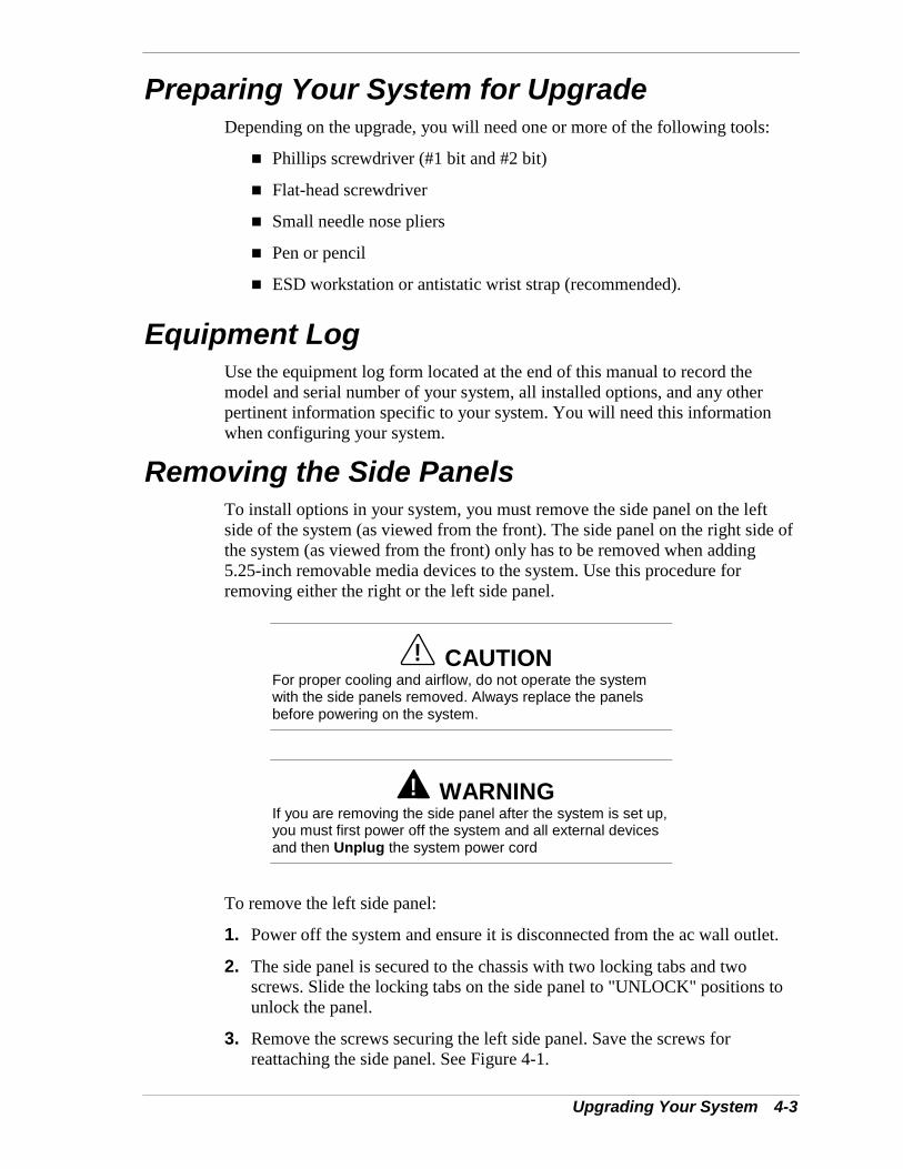
Preparing Your System for UpgradeDepending on the upgrade, you will need one or more of the following tools:
! Phillips screwdriver (#1 bit and #2 bit)
! Flat-head screwdriver
! Small needle nose pliers
! Pen or pencil
! ESD workstation or antistatic wrist strap (recommended).
Equipment LogUse the equipment log form located at the end of this manual to record themodel and serial number of your system, all installed options, and any otherpertinent information specific to your system. You will need this informationwhen configuring your system.
Removing the Side PanelsTo install options in your system, you must remove the side panel on the leftside of the system (as viewed from the front). The side panel on the right side ofthe system (as viewed from the front) only has to be removed when adding5.25-inch removable media devices to the system. Use this procedure forremoving either the right or the left side panel.
! CAUTIONFor proper cooling and airflow, do not operate the systemwith the side panels removed. Always replace the panelsbefore powering on the system.
! WARNINGIf you are removing the side panel after the system is set up,you must first power off the system and all external devicesand then Unplug the system power cord
To remove the left side panel:
1. Power off the system and ensure it is disconnected from the ac wall outlet.
2. The side panel is secured to the chassis with two locking tabs and twoscrews. Slide the locking tabs on the side panel to "UNLOCK" positions tounlock the panel.
3. Remove the screws securing the left side panel. Save the screws forreattaching the side panel. See Figure 4-1.
4-4 Upgrading Your System
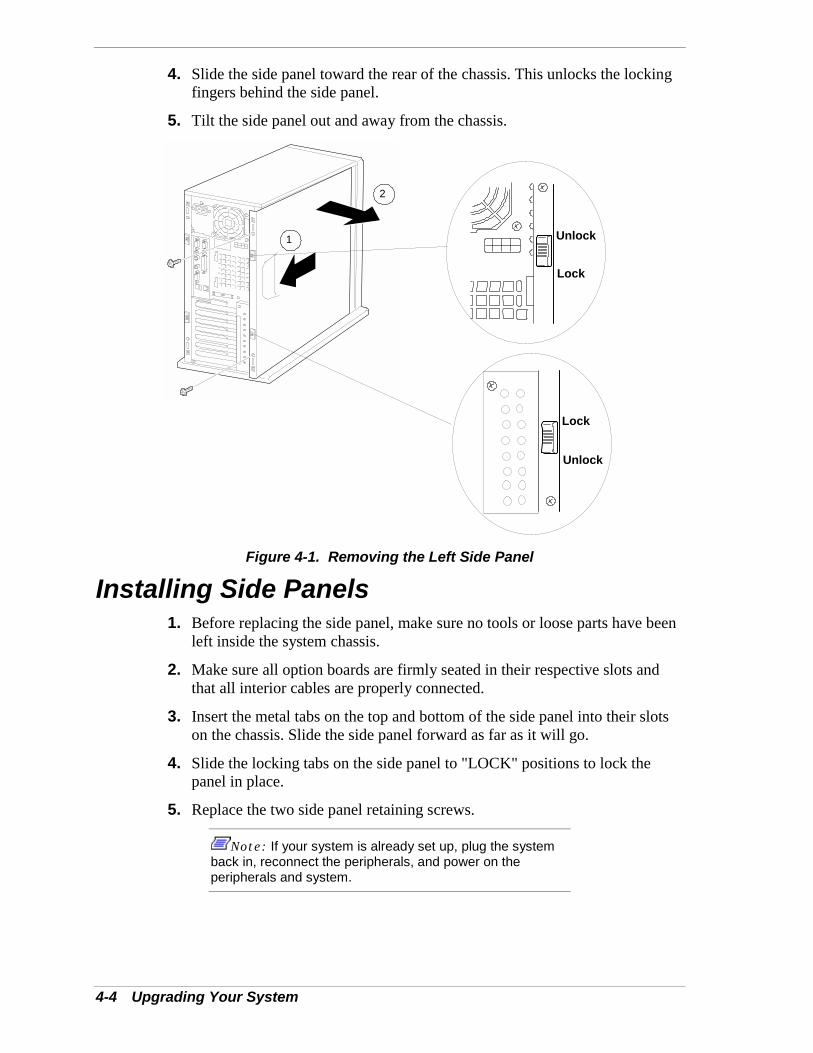
4. Slide the side panel toward the rear of the chassis. This unlocks the lockingfingers behind the side panel.
5. Tilt the side panel out and away from the chassis.
1
2
Lock
Unlock
Lock
Unlock
Figure 4-1. Removing the Left Side Panel
Installing Side Panels1. Before replacing the side panel, make sure no tools or loose parts have been
left inside the system chassis.
2. Make sure all option boards are firmly seated in their respective slots andthat all interior cables are properly connected.
3. Insert the metal tabs on the top and bottom of the side panel into their slotson the chassis. Slide the side panel forward as far as it will go.
4. Slide the locking tabs on the side panel to "LOCK" positions to lock thepanel in place.
5. Replace the two side panel retaining screws.
Note: If your system is already set up, plug the systemback in, reconnect the peripherals, and power on theperipherals and system.
Upgrading Your System 4-5
Modifying the System BoardThe following sections provide procedures for upgrading and configuring thesystem board in your system. Topics covered include:
! Replacing the real-time clock battery
! Removing and installing a Pentium processor
! Installing or removing DIMMs.
! CAUTIONElectrostatic discharge (ESD) can damage add-in boardsand other components; place them on an antistatic surface.Modify the system board only at an ESD workstation.Otherwise, wear an antistatic wrist strap attached to chassisground.
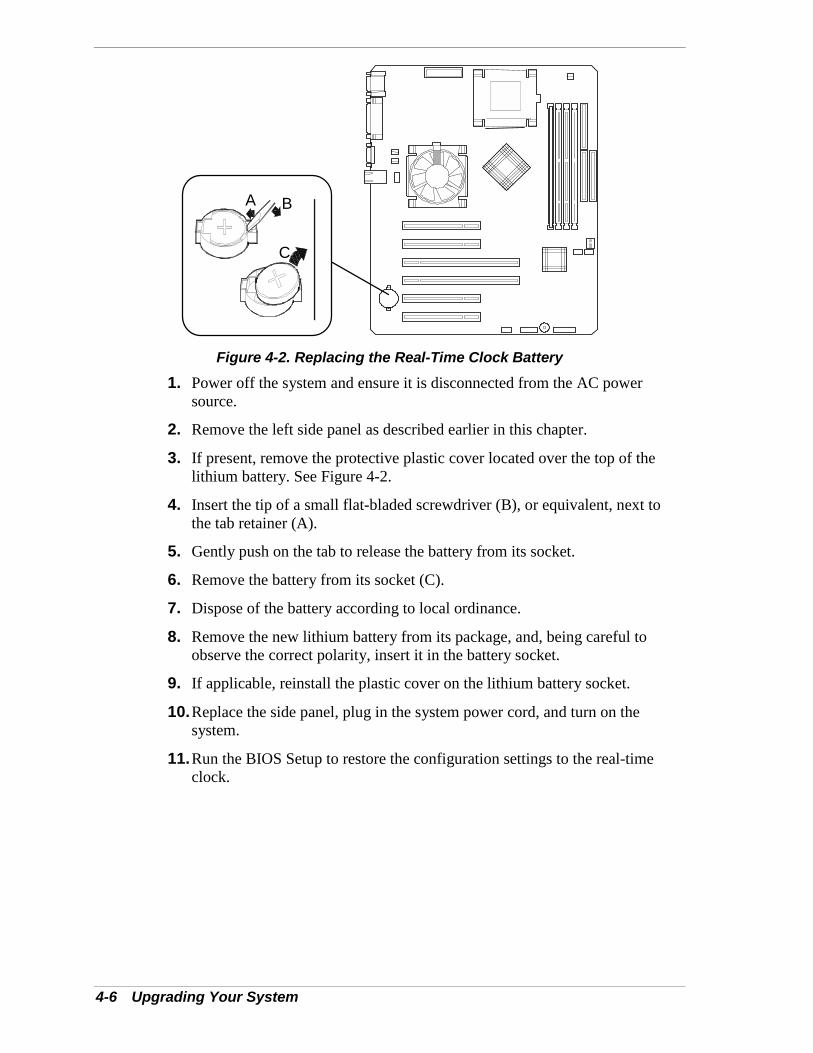
Replacing the Real-time Clock BatteryYou may need to replace the real-time clock battery because of its life span. Thebattery (Vendor Part #CR2032) is a commodity part available through manyvendors. Notice the plus (+) sign on the battery. This sign will assist you incorrectly positioning the battery on the system board.
! CAUTIONDanger of explosion if battery is incorrectly replaced.Replace only with same or equivalent type recommended bymanufacturer. Dispose of lithium batteries as required bylocal ordinance or as normal waste if no local ordinanceexists. Do not expose the component to excessive heat orfire. Keep all batteries away from children
! CAUTIONObserve static precautions. Use an antistatic wrist strap.
4-6 Upgrading Your System
A B
C
Figure 4-2. Replacing the Real-Time Clock Battery1. Power off the system and ensure it is disconnected from the AC power
source.
2. Remove the left side panel as described earlier in this chapter.
3. If present, remove the protective plastic cover located over the top of thelithium battery. See Figure 4-2.
4. Insert the tip of a small flat-bladed screwdriver (B), or equivalent, next tothe tab retainer (A).
5. Gently push on the tab to release the battery from its socket.
6. Remove the battery from its socket (C).
7. Dispose of the battery according to local ordinance.
8. Remove the new lithium battery from its package, and, being careful toobserve the correct polarity, insert it in the battery socket.
9. If applicable, reinstall the plastic cover on the lithium battery socket.
10. Replace the side panel, plug in the system power cord, and turn on thesystem.
11. Run the BIOS Setup to restore the configuration settings to the real-timeclock.
Upgrading Your System 4-7
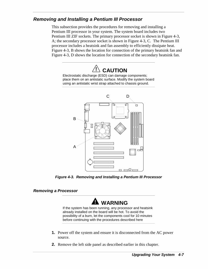
Removing and Installing a Pentium III ProcessorThis subsection provides the procedures for removing and installing aPentium III processor in your system. The system board includes twoPentium III ZIF sockets. The primary processor socket is shown in Figure 4-3,A; the secondary processor socket is shown in Figure 4-3, C. The Pentium IIIprocessor includes a heatsink and fan assembly to efficiently dissipate heat.Figure 4-3, B shows the location for connection of the primary heatsink fan andFigure 4-3, D shows the location for connection of the secondary heatsink fan.
! CAUTIONElectrostatic discharge (ESD) can damage components;place them on an antistatic surface. Modify the system boardusing an antistatic wrist strap attached to chassis ground.
A
B
C D
Figure 4-3. Removing and Installing a Pentium III Processor
Removing a Processor
! WARNINGIf the system has been running, any processor and heatsinkalready installed on the board will be hot. To avoid thepossibility of a burn, let the components cool for 10 minutesbefore continuing with the procedures described here
1. Power off the system and ensure it is disconnected from the AC powersource.
2. Remove the left side panel as described earlier in this chapter.
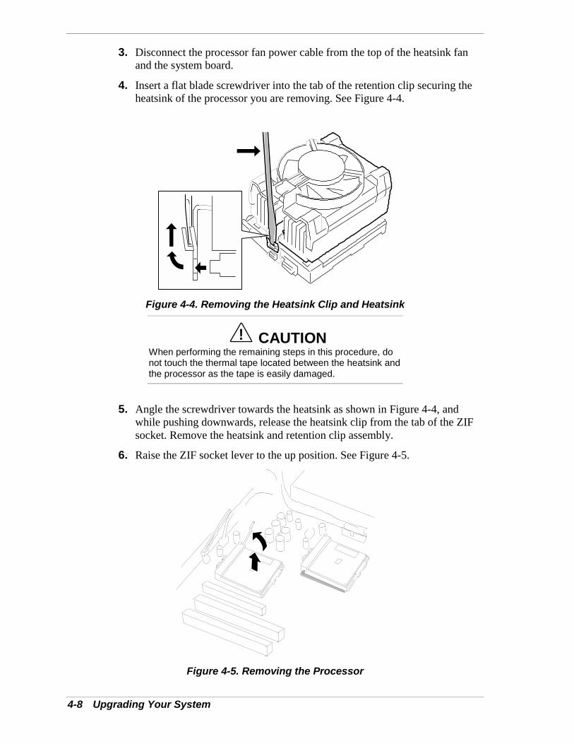
4-8 Upgrading Your System
3. Disconnect the processor fan power cable from the top of the heatsink fanand the system board.
4. Insert a flat blade screwdriver into the tab of the retention clip securing theheatsink of the processor you are removing. See Figure 4-4.
Figure 4-4. Removing the Heatsink Clip and Heatsink
! CAUTIONWhen performing the remaining steps in this procedure, donot touch the thermal tape located between the heatsink andthe processor as the tape is easily damaged.
5. Angle the screwdriver towards the heatsink as shown in Figure 4-4, andwhile pushing downwards, release the heatsink clip from the tab of the ZIFsocket. Remove the heatsink and retention clip assembly.
6. Raise the ZIF socket lever to the up position. See Figure 4-5.
Figure 4-5. Removing the Processor
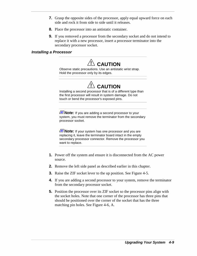
Upgrading Your System 4-9
7. Grasp the opposite sides of the processor, apply equal upward force on eachside and rock it from side to side until it releases.
8. Place the processor into an antistatic container.
9. If you removed a processor from the secondary socket and do not intend toreplace it with a new processor, insert a processor terminator into thesecondary processor socket.
Installing a Processor
! CAUTIONObserve static precautions. Use an antistatic wrist strap.Hold the processor only by its edges.
! CAUTIONInstalling a second processor that is of a different type thanthe first processor will result in system damage. Do nottouch or bend the processor's exposed pins.
Note: If you are adding a second processor to yoursystem, you must remove the terminator from the secondaryprocessor socket.
Note: If your system has one processor and you arereplacing it, leave the terminator board intact in the emptysecondary processor connector. Remove the processor youwant to replace.
1. Power off the system and ensure it is disconnected from the AC powersource.
2. Remove the left side panel as described earlier in this chapter.
3. Raise the ZIF socket lever to the up position. See Figure 4-5.
4. If you are adding a second processor to your system, remove the terminatorfrom the secondary processor socket.
5. Position the processor over its ZIF socket so the processor pins align withthe socket holes. Note that one corner of the processor has three pins thatshould be positioned over the corner of the socket that has the threematching pin holes. See Figure 4-6, A.
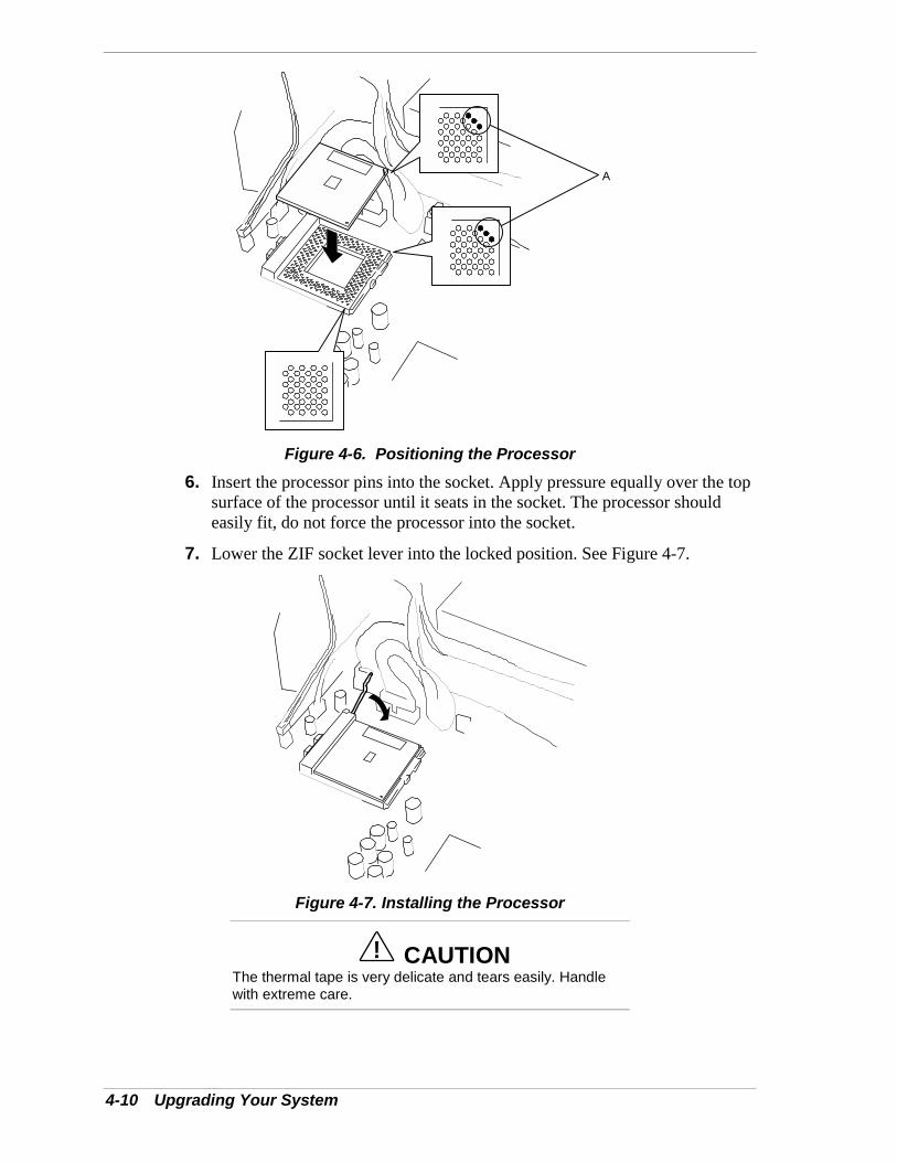
4-10 Upgrading Your System
A
Figure 4-6. Positioning the Processor6. Insert the processor pins into the socket. Apply pressure equally over the top
surface of the processor until it seats in the socket. The processor shouldeasily fit, do not force the processor into the socket.
7. Lower the ZIF socket lever into the locked position. See Figure 4-7.
Figure 4-7. Installing the Processor
! CAUTIONThe thermal tape is very delicate and tears easily. Handlewith extreme care.
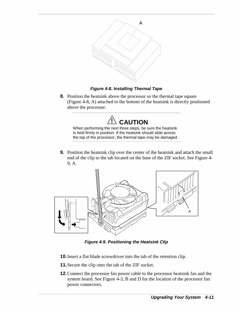
Upgrading Your System 4-11
A
Figure 4-8. Installing Thermal Tape8. Position the heatsink above the processor so the thermal tape square
(Figure 4-8, A) attached to the bottom of the heatsink is directly positionedabove the processor.
! CAUTIONWhen performing the next three steps, be sure the heatsinkis held firmly in position. If the heatsink should slide acrossthe top of the processor, the thermal tape may be damaged.
9. Position the heatsink clip over the center of the heatsink and attach the smallend of the clip to the tab located on the base of the ZIF socket. See Figure 4-9, A.
A
Figure 4-9. Positioning the Heatsink Clip
10. Insert a flat blade screwdriver into the tab of the retention clip.
11. Secure the clip onto the tab of the ZIF socket.
12. Connect the processor fan power cable to the processor heatsink fan and thesystem board. See Figure 4-3, B and D for the location of the processor fanpower connectors.
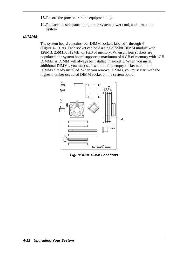
4-12 Upgrading Your System
13. Record the processor in the equipment log.
14. Replace the side panel, plug in the system power cord, and turn on thesystem.
DIMMsThe system board contains four DIMM sockets labeled 1 through 4(Figure 4-10, A). Each socket can hold a single 72-bit DIMM module with128MB, 256MB, 512MB, or 1GB of memory. When all four sockets arepopulated, the system board supports a maximum of 4 GB of memory with 1GBDIMMs. A DIMM will always be installed in socket 1. When you installadditional DIMMs, you must start with the first empty socket next to theDIMMs already installed. When you remove DIMMs, you must start with thehighest number occupied DIMM socket on the system board.
1 32 4
A
Figure 4-10. DIMM Locations
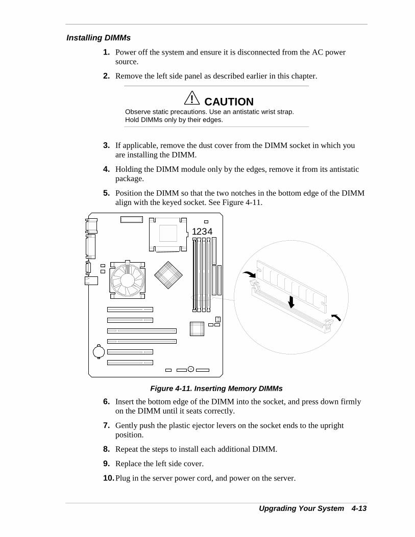
Upgrading Your System 4-13
Installing DIMMs
1. Power off the system and ensure it is disconnected from the AC powersource.
2. Remove the left side panel as described earlier in this chapter.
! CAUTIONObserve static precautions. Use an antistatic wrist strap.Hold DIMMs only by their edges.
3. If applicable, remove the dust cover from the DIMM socket in which youare installing the DIMM.
4. Holding the DIMM module only by the edges, remove it from its antistaticpackage.
5. Position the DIMM so that the two notches in the bottom edge of the DIMMalign with the keyed socket. See Figure 4-11.
1 32 4
Figure 4-11. Inserting Memory DIMMs
6. Insert the bottom edge of the DIMM into the socket, and press down firmlyon the DIMM until it seats correctly.
7. Gently push the plastic ejector levers on the socket ends to the uprightposition.
8. Repeat the steps to install each additional DIMM.
9. Replace the left side cover.
10. Plug in the server power cord, and power on the server.
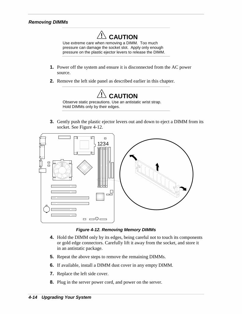
4-14 Upgrading Your System
Removing DIMMs
! CAUTIONUse extreme care when removing a DIMM. Too muchpressure can damage the socket slot. Apply only enoughpressure on the plastic ejector levers to release the DIMM.
1. Power off the system and ensure it is disconnected from the AC powersource.
2. Remove the left side panel as described earlier in this chapter.
! CAUTIONObserve static precautions. Use an antistatic wrist strap.Hold DIMMs only by their edges.
3. Gently push the plastic ejector levers out and down to eject a DIMM from itssocket. See Figure 4-12.
1 32 4
Figure 4-12. Removing Memory DIMMs4. Hold the DIMM only by its edges, being careful not to touch its components
or gold edge connectors. Carefully lift it away from the socket, and store itin an antistatic package.
5. Repeat the above steps to remove the remaining DIMMs.
6. If available, install a DIMM dust cover in any empty DIMM.
7. Replace the left side cover.
8. Plug in the server power cord, and power on the server.
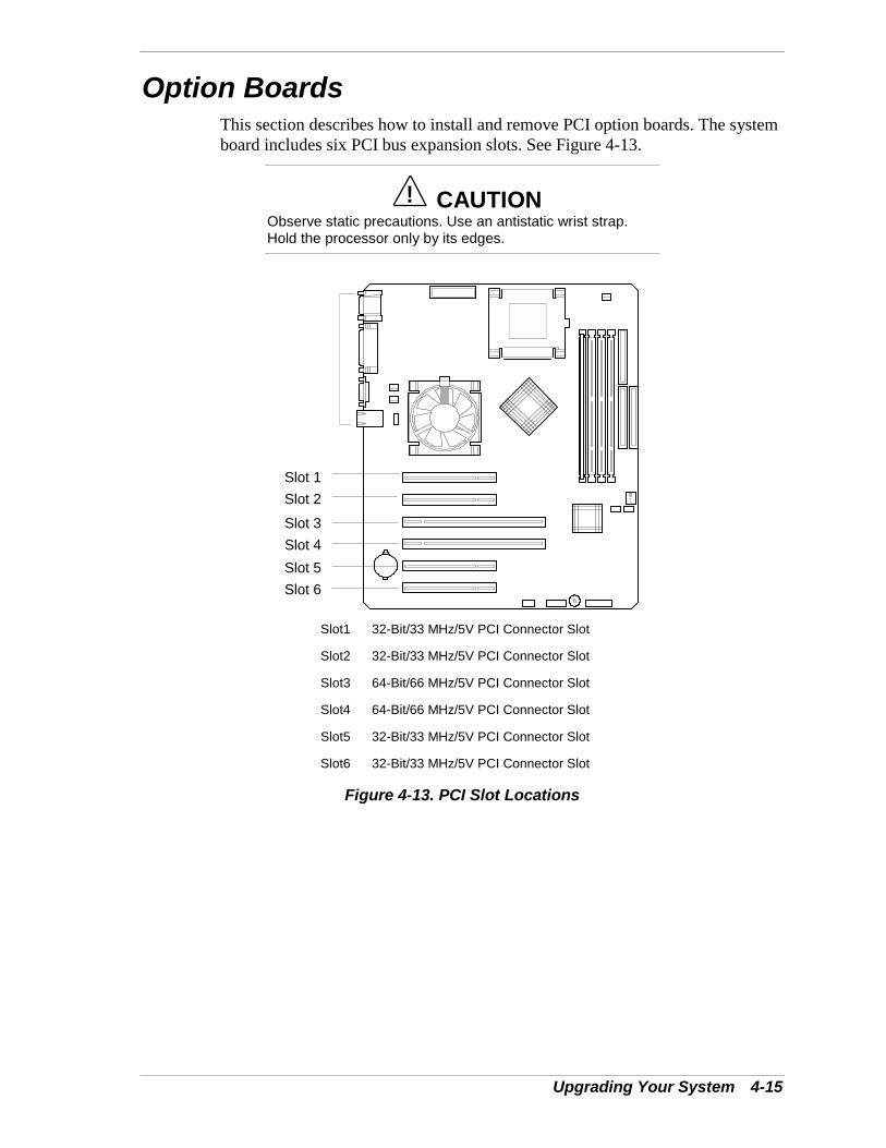
Upgrading Your System 4-15
Option BoardsThis section describes how to install and remove PCI option boards. The systemboard includes six PCI bus expansion slots. See Figure 4-13.
! CAUTIONObserve static precautions. Use an antistatic wrist strap.Hold the processor only by its edges.
Slot 1Slot 2Slot 3Slot 4Slot 5Slot 6
Slot1 32-Bit/33 MHz/5V PCI Connector Slot
Slot2 32-Bit/33 MHz/5V PCI Connector Slot
Slot3 64-Bit/66 MHz/5V PCI Connector Slot
Slot4 64-Bit/66 MHz/5V PCI Connector Slot
Slot5 32-Bit/33 MHz/5V PCI Connector Slot
Slot6 32-Bit/33 MHz/5V PCI Connector Slot
Figure 4-13. PCI Slot Locations
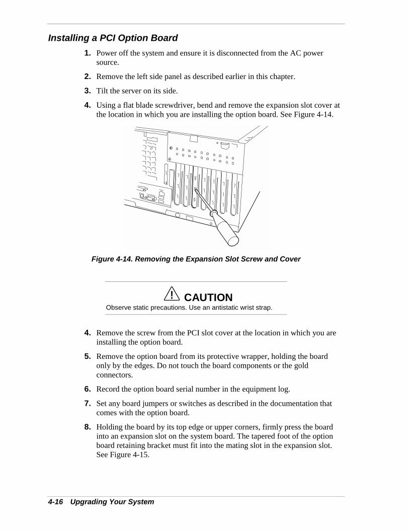
4-16 Upgrading Your System
Installing a PCI Option Board1. Power off the system and ensure it is disconnected from the AC power
source.
2. Remove the left side panel as described earlier in this chapter.
3. Tilt the server on its side.
4. Using a flat blade screwdriver, bend and remove the expansion slot cover atthe location in which you are installing the option board. See Figure 4-14.
Figure 4-14. Removing the Expansion Slot Screw and Cover
! CAUTIONObserve static precautions. Use an antistatic wrist strap.
4. Remove the screw from the PCI slot cover at the location in which you areinstalling the option board.
5. Remove the option board from its protective wrapper, holding the boardonly by the edges. Do not touch the board components or the goldconnectors.
6. Record the option board serial number in the equipment log.
7. Set any board jumpers or switches as described in the documentation thatcomes with the option board.
8. Holding the board by its top edge or upper corners, firmly press the boardinto an expansion slot on the system board. The tapered foot of the optionboard retaining bracket must fit into the mating slot in the expansion slot.See Figure 4-15.
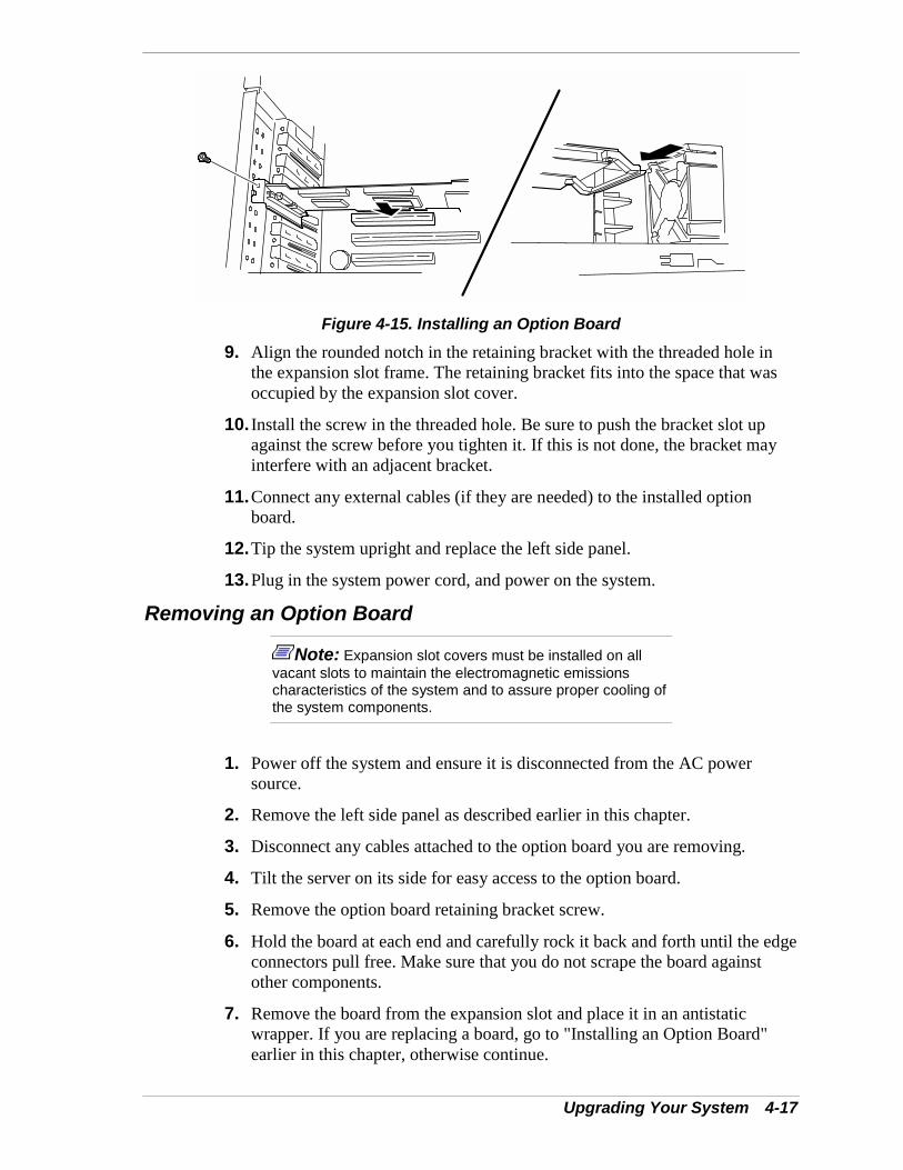
Upgrading Your System 4-17
Figure 4-15. Installing an Option Board9. Align the rounded notch in the retaining bracket with the threaded hole in
the expansion slot frame. The retaining bracket fits into the space that wasoccupied by the expansion slot cover.
10. Install the screw in the threaded hole. Be sure to push the bracket slot upagainst the screw before you tighten it. If this is not done, the bracket mayinterfere with an adjacent bracket.
11. Connect any external cables (if they are needed) to the installed optionboard.
12. Tip the system upright and replace the left side panel.
13. Plug in the system power cord, and power on the system.
Removing an Option Board
Note: Expansion slot covers must be installed on allvacant slots to maintain the electromagnetic emissionscharacteristics of the system and to assure proper cooling ofthe system components.
1. Power off the system and ensure it is disconnected from the AC powersource.
2. Remove the left side panel as described earlier in this chapter.
3. Disconnect any cables attached to the option board you are removing.
4. Tilt the server on its side for easy access to the option board.
5. Remove the option board retaining bracket screw.
6. Hold the board at each end and carefully rock it back and forth until the edgeconnectors pull free. Make sure that you do not scrape the board againstother components.
7. Remove the board from the expansion slot and place it in an antistaticwrapper. If you are replacing a board, go to "Installing an Option Board"earlier in this chapter, otherwise continue.
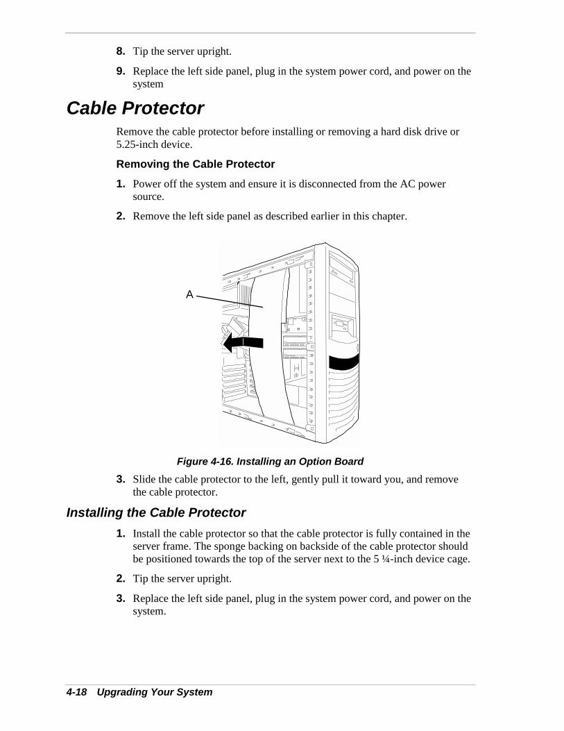
4-18 Upgrading Your System
8. Tip the server upright.
9. Replace the left side panel, plug in the system power cord, and power on thesystem
Cable ProtectorRemove the cable protector before installing or removing a hard disk drive or5.25-inch device.
Removing the Cable Protector1. Power off the system and ensure it is disconnected from the AC power
source.
2. Remove the left side panel as described earlier in this chapter.
Figure 4-16. Installing an Option Board3. Slide the cable protector to the left, gently pull it toward you, and remove
the cable protector.
Installing the Cable Protector1. Install the cable protector so that the cable protector is fully contained in the
server frame. The sponge backing on backside of the cable protector shouldbe positioned towards the top of the server next to the 5 ¼-inch device cage.
2. Tip the server upright.
3. Replace the left side panel, plug in the system power cord, and power on thesystem.
A
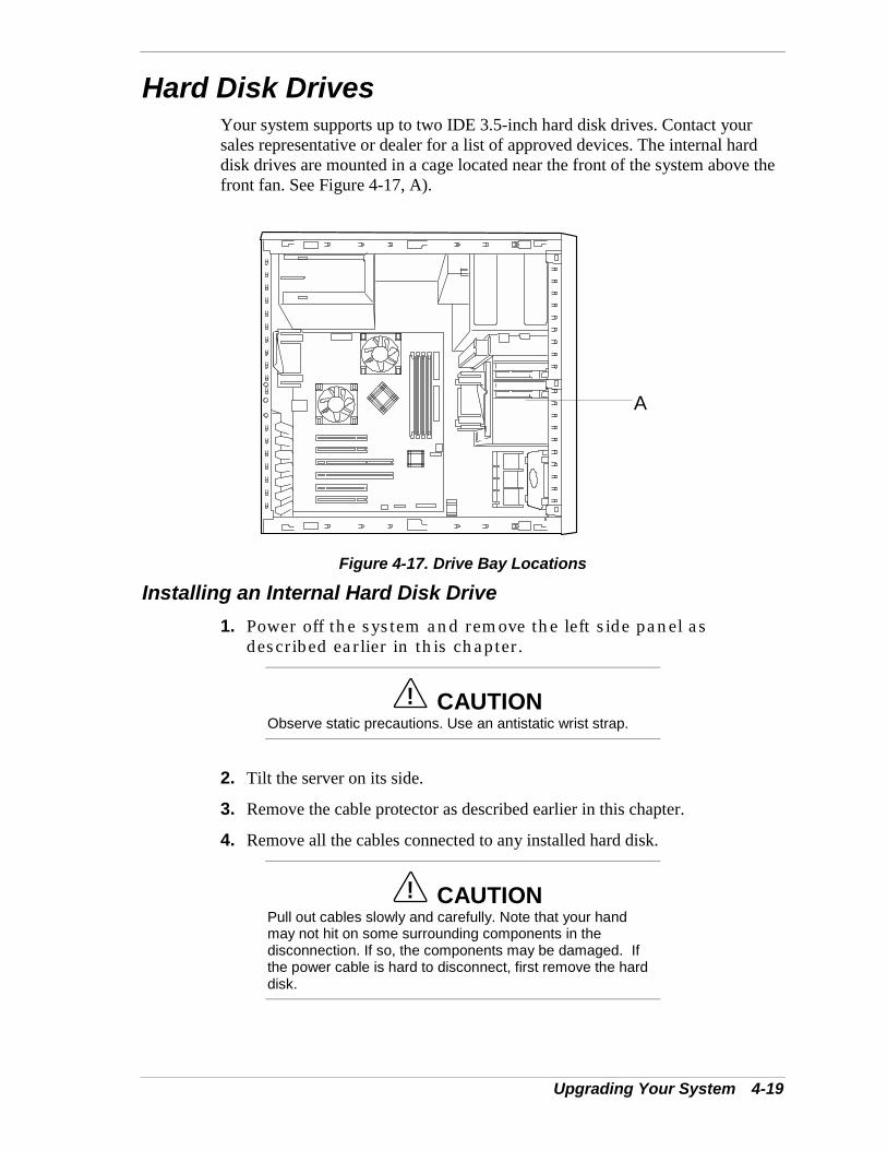
Upgrading Your System 4-19
Hard Disk DrivesYour system supports up to two IDE 3.5-inch hard disk drives. Contact yoursales representative or dealer for a list of approved devices. The internal harddisk drives are mounted in a cage located near the front of the system above thefront fan. See Figure 4-17, A).
A
Figure 4-17. Drive Bay Locations
Installing an Internal Hard Disk Drive1. Power off the system and remove the left side panel as
described earlier in this chapter.
! CAUTIONObserve static precautions. Use an antistatic wrist strap.
2. Tilt the server on its side.
3. Remove the cable protector as described earlier in this chapter.
4. Remove all the cables connected to any installed hard disk.
! CAUTIONPull out cables slowly and carefully. Note that your handmay not hit on some surrounding components in thedisconnection. If so, the components may be damaged. Ifthe power cable is hard to disconnect, first remove the harddisk.
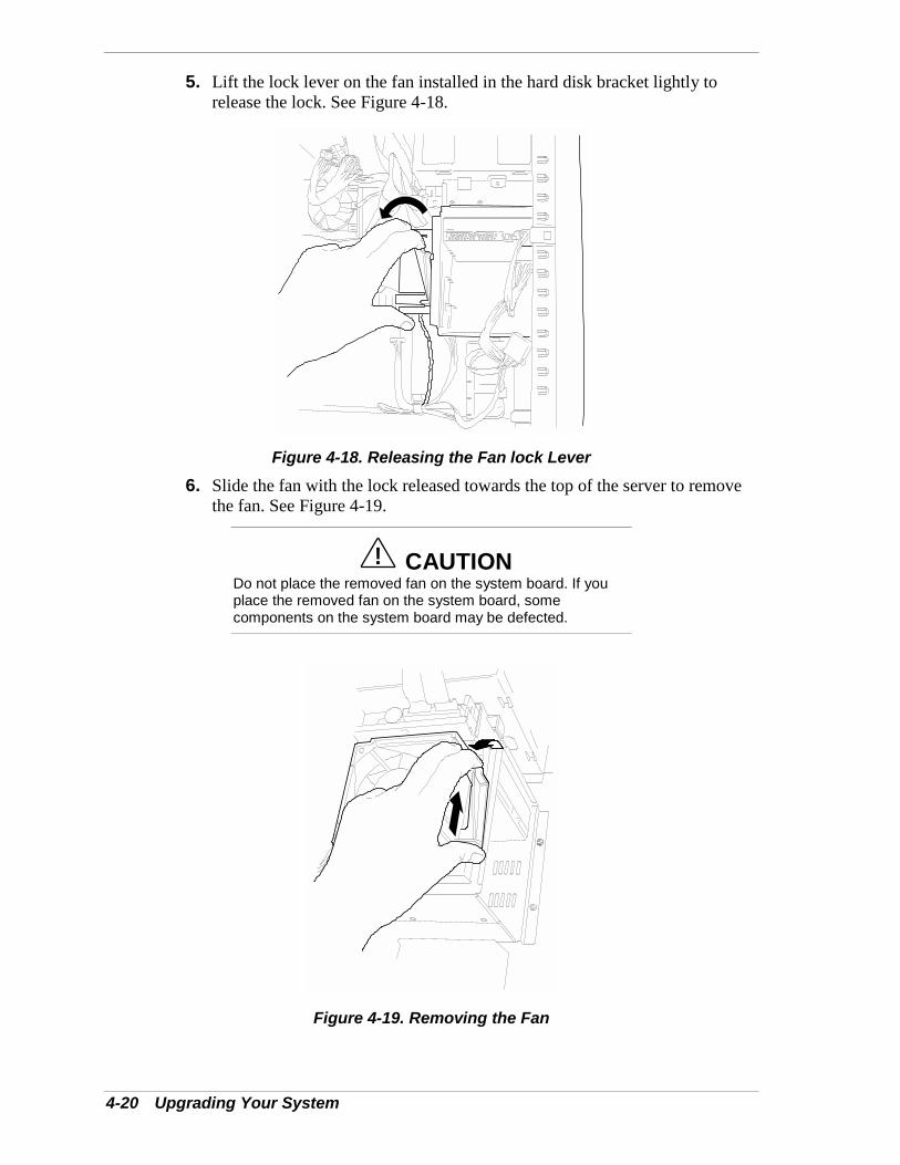
4-20 Upgrading Your System
5. Lift the lock lever on the fan installed in the hard disk bracket lightly torelease the lock. See Figure 4-18.
Figure 4-18. Releasing the Fan lock Lever6. Slide the fan with the lock released towards the top of the server to remove
the fan. See Figure 4-19.
! CAUTIONDo not place the removed fan on the system board. If youplace the removed fan on the system board, somecomponents on the system board may be defected.
Figure 4-19. Removing the Fan
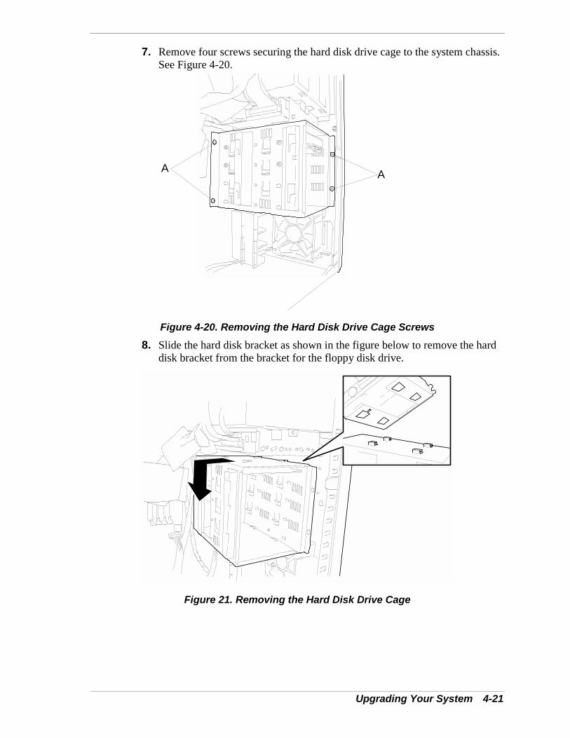
Upgrading Your System 4-21
7. Remove four screws securing the hard disk drive cage to the system chassis.See Figure 4-20.
A A
Figure 4-20. Removing the Hard Disk Drive Cage Screws
8. Slide the hard disk bracket as shown in the figure below to remove the harddisk bracket from the bracket for the floppy disk drive.
Figure 21. Removing the Hard Disk Drive Cage
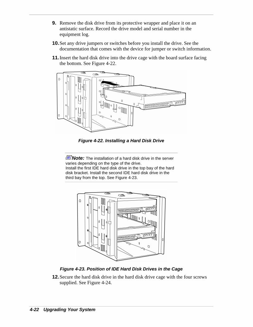
4-22 Upgrading Your System
9. Remove the disk drive from its protective wrapper and place it on anantistatic surface. Record the drive model and serial number in theequipment log.
10. Set any drive jumpers or switches before you install the drive. See thedocumentation that comes with the device for jumper or switch information.
11. Insert the hard disk drive into the drive cage with the board surface facingthe bottom. See Figure 4-22.
Figure 4-22. Installing a Hard Disk Drive
Note: The installation of a hard disk drive in the servervaries depending on the type of the drive.Install the first IDE hard disk drive in the top bay of the harddisk bracket. Install the second IDE hard disk drive in thethird bay from the top. See Figure 4-23.
Figure 4-23. Position of IDE Hard Disk Drives in the Cage
12. Secure the hard disk drive in the hard disk drive cage with the four screwssupplied. See Figure 4-24.
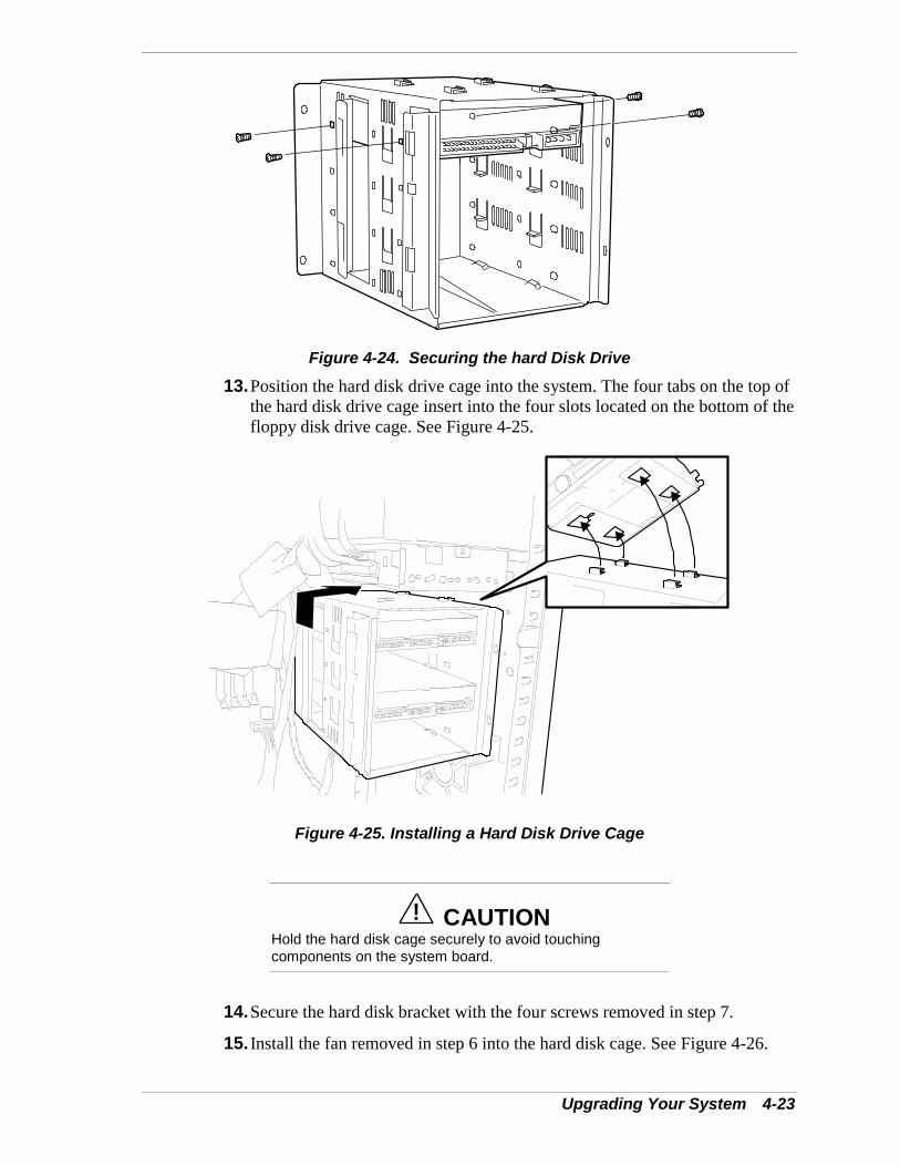
Upgrading Your System 4-23
Figure 4-24. Securing the hard Disk Drive13. Position the hard disk drive cage into the system. The four tabs on the top of
the hard disk drive cage insert into the four slots located on the bottom of thefloppy disk drive cage. See Figure 4-25.
Figure 4-25. Installing a Hard Disk Drive Cage
! CAUTIONHold the hard disk cage securely to avoid touchingcomponents on the system board.
14. Secure the hard disk bracket with the four screws removed in step 7.
15. Install the fan removed in step 6 into the hard disk cage. See Figure 4-26.
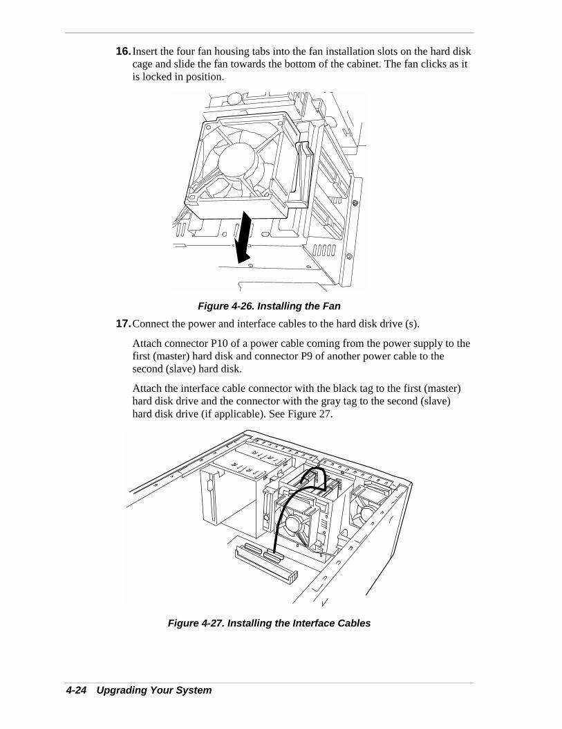
4-24 Upgrading Your System
16. Insert the four fan housing tabs into the fan installation slots on the hard diskcage and slide the fan towards the bottom of the cabinet. The fan clicks as itis locked in position.
Figure 4-26. Installing the Fan17. Connect the power and interface cables to the hard disk drive (s).
Attach connector P10 of a power cable coming from the power supply to thefirst (master) hard disk and connector P9 of another power cable to thesecond (slave) hard disk.
Attach the interface cable connector with the black tag to the first (master)hard disk drive and the connector with the gray tag to the second (slave)hard disk drive (if applicable). See Figure 27.
Figure 4-27. Installing the Interface Cables
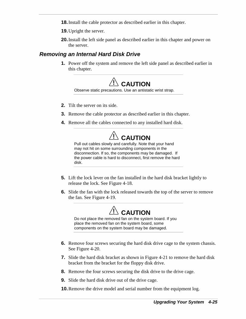
Upgrading Your System 4-25
18. Install the cable protector as described earlier in this chapter.
19. Upright the server.
20. Install the left side panel as described earlier in this chapter and power onthe server.
Removing an Internal Hard Disk Drive1. Power off the system and remove the left side panel as described earlier in
this chapter.
! CAUTIONObserve static precautions. Use an antistatic wrist strap.
2. Tilt the server on its side.
3. Remove the cable protector as described earlier in this chapter.
4. Remove all the cables connected to any installed hard disk.
! CAUTIONPull out cables slowly and carefully. Note that your handmay not hit on some surrounding components in thedisconnection. If so, the components may be damaged. Ifthe power cable is hard to disconnect, first remove the harddisk.
5. Lift the lock lever on the fan installed in the hard disk bracket lightly torelease the lock. See Figure 4-18.
6. Slide the fan with the lock released towards the top of the server to removethe fan. See Figure 4-19.
! CAUTIONDo not place the removed fan on the system board. If youplace the removed fan on the system board, somecomponents on the system board may be damaged.
6. Remove four screws securing the hard disk drive cage to the system chassis.See Figure 4-20.
7. Slide the hard disk bracket as shown in Figure 4-21 to remove the hard diskbracket from the bracket for the floppy disk drive.
8. Remove the four screws securing the disk drive to the drive cage.
9. Slide the hard disk drive out of the drive cage.
10. Remove the drive model and serial number from the equipment log.
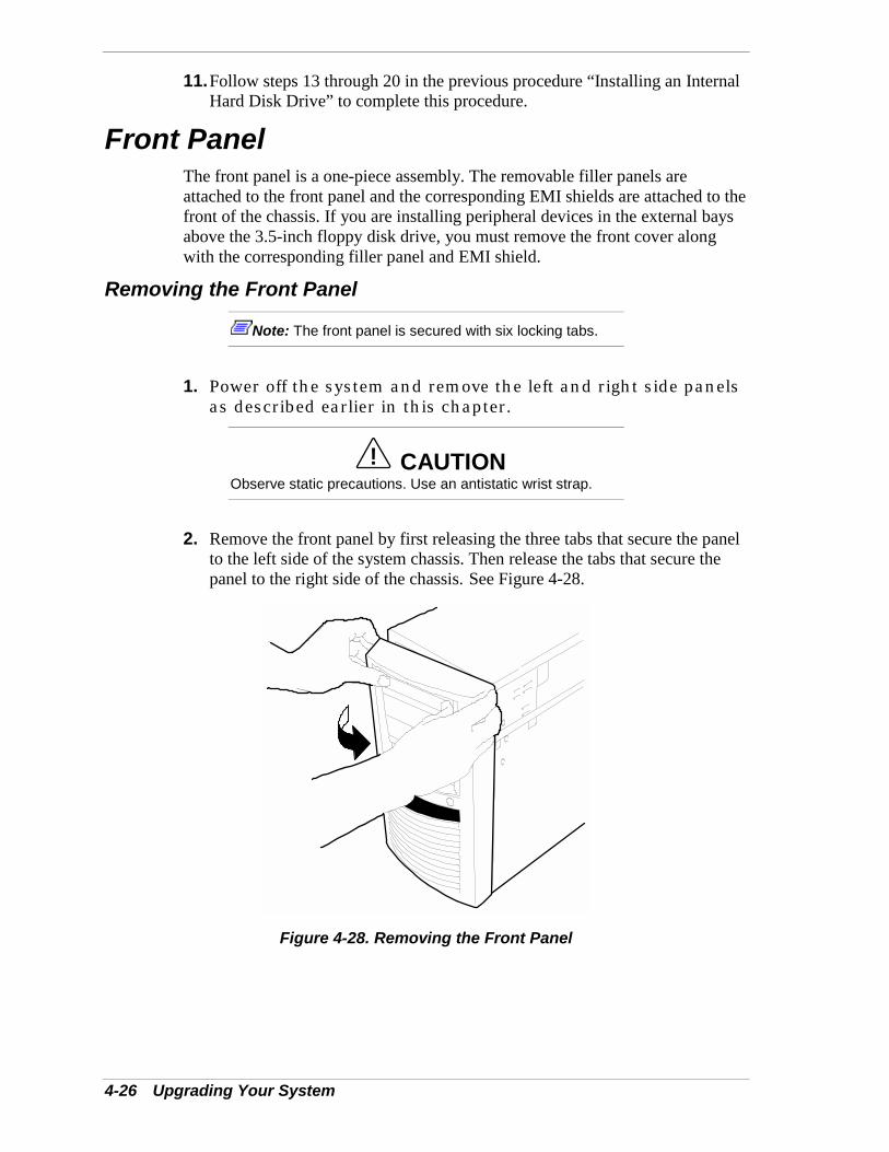
4-26 Upgrading Your System
11. Follow steps 13 through 20 in the previous procedure “Installing an InternalHard Disk Drive” to complete this procedure.
Front PanelThe front panel is a one-piece assembly. The removable filler panels areattached to the front panel and the corresponding EMI shields are attached to thefront of the chassis. If you are installing peripheral devices in the external baysabove the 3.5-inch floppy disk drive, you must remove the front cover alongwith the corresponding filler panel and EMI shield.
Removing the Front Panel
Note: The front panel is secured with six locking tabs.
1. Power off the system and remove the left and right side panelsas described earlier in this chapter.
! CAUTIONObserve static precautions. Use an antistatic wrist strap.
2. Remove the front panel by first releasing the three tabs that secure the panelto the left side of the system chassis. Then release the tabs that secure thepanel to the right side of the chassis. See Figure 4-28.
Figure 4-28. Removing the Front Panel
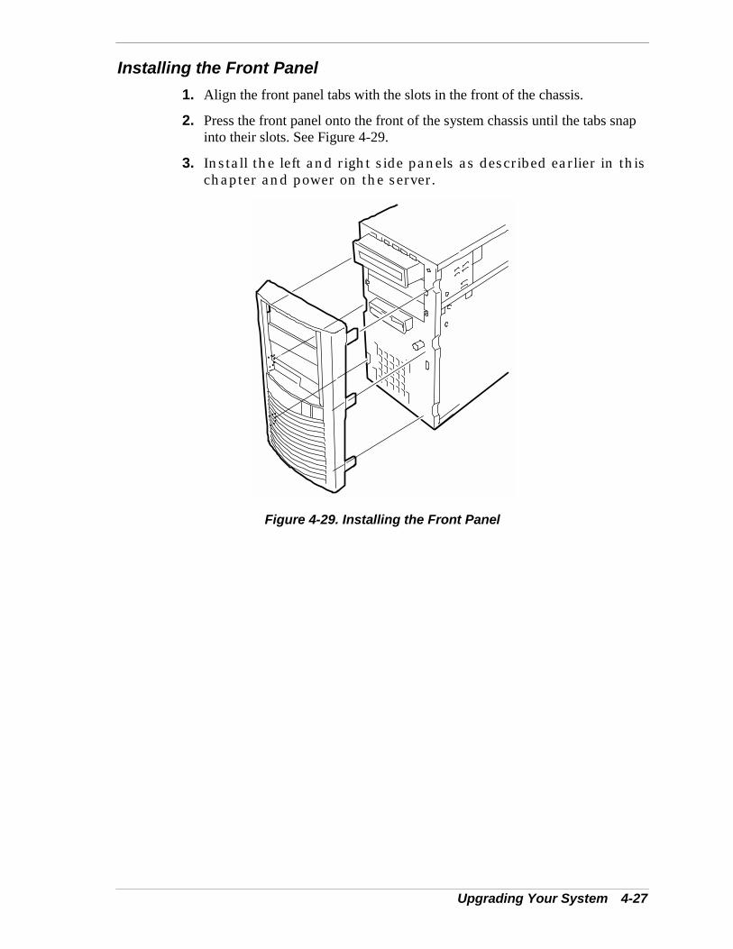
Upgrading Your System 4-27
Installing the Front Panel1. Align the front panel tabs with the slots in the front of the chassis.
2. Press the front panel onto the front of the system chassis until the tabs snapinto their slots. See Figure 4-29.
3. Install the left and right side panels as described earlier in thischapter and power on the server.
Figure 4-29. Installing the Front Panel
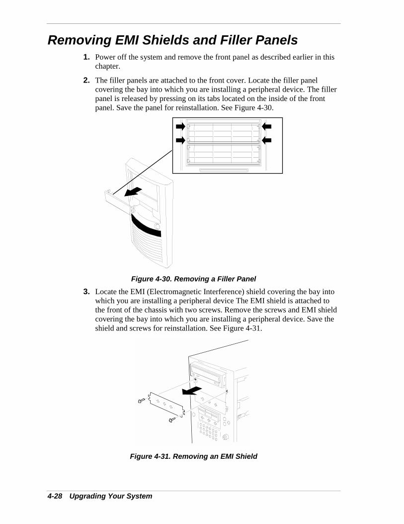
4-28 Upgrading Your System
Removing EMI Shields and Filler Panels1. Power off the system and remove the front panel as described earlier in this
chapter.
2. The filler panels are attached to the front cover. Locate the filler panelcovering the bay into which you are installing a peripheral device. The fillerpanel is released by pressing on its tabs located on the inside of the frontpanel. Save the panel for reinstallation. See Figure 4-30.
Figure 4-30. Removing a Filler Panel3. Locate the EMI (Electromagnetic Interference) shield covering the bay into
which you are installing a peripheral device The EMI shield is attached tothe front of the chassis with two screws. Remove the screws and EMI shieldcovering the bay into which you are installing a peripheral device. Save theshield and screws for reinstallation. See Figure 4-31.
Figure 4-31. Removing an EMI Shield
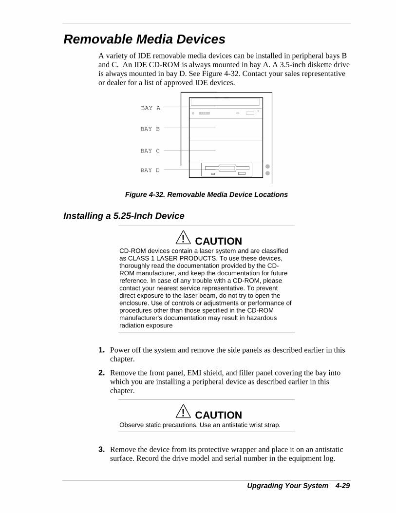
Upgrading Your System 4-29
Removable Media DevicesA variety of IDE removable media devices can be installed in peripheral bays Band C. An IDE CD-ROM is always mounted in bay A. A 3.5-inch diskette driveis always mounted in bay D. See Figure 4-32. Contact your sales representativeor dealer for a list of approved IDE devices.
BAY A
BAY B
BAY C
BAY D
Figure 4-32. Removable Media Device Locations
Installing a 5.25-Inch Device
! CAUTIONCD-ROM devices contain a laser system and are classifiedas CLASS 1 LASER PRODUCTS. To use these devices,thoroughly read the documentation provided by the CD-ROM manufacturer, and keep the documentation for futurereference. In case of any trouble with a CD-ROM, pleasecontact your nearest service representative. To preventdirect exposure to the laser beam, do not try to open theenclosure. Use of controls or adjustments or performance ofprocedures other than those specified in the CD-ROMmanufacturer's documentation may result in hazardousradiation exposure
1. Power off the system and remove the side panels as described earlier in thischapter.
2. Remove the front panel, EMI shield, and filler panel covering the bay intowhich you are installing a peripheral device as described earlier in thischapter.
! CAUTIONObserve static precautions. Use an antistatic wrist strap.
3. Remove the device from its protective wrapper and place it on an antistaticsurface. Record the drive model and serial number in the equipment log.
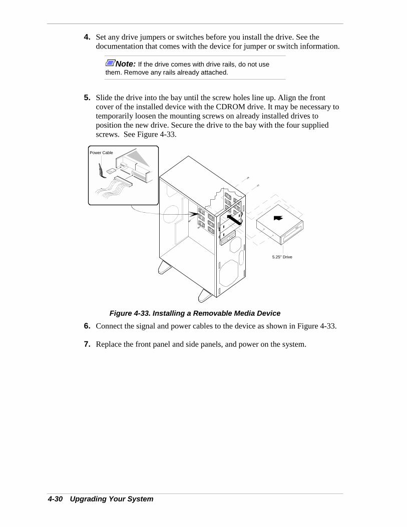
4-30 Upgrading Your System
4. Set any drive jumpers or switches before you install the drive. See thedocumentation that comes with the device for jumper or switch information.
Note: If the drive comes with drive rails, do not usethem. Remove any rails already attached.
5. Slide the drive into the bay until the screw holes line up. Align the frontcover of the installed device with the CDROM drive. It may be necessary totemporarily loosen the mounting screws on already installed drives toposition the new drive. Secure the drive to the bay with the four suppliedscrews. See Figure 4-33.
5.25" Drive
Power Cable
Figure 4-33. Installing a Removable Media Device6. Connect the signal and power cables to the device as shown in Figure 4-33.
7. Replace the front panel and side panels, and power on the system.
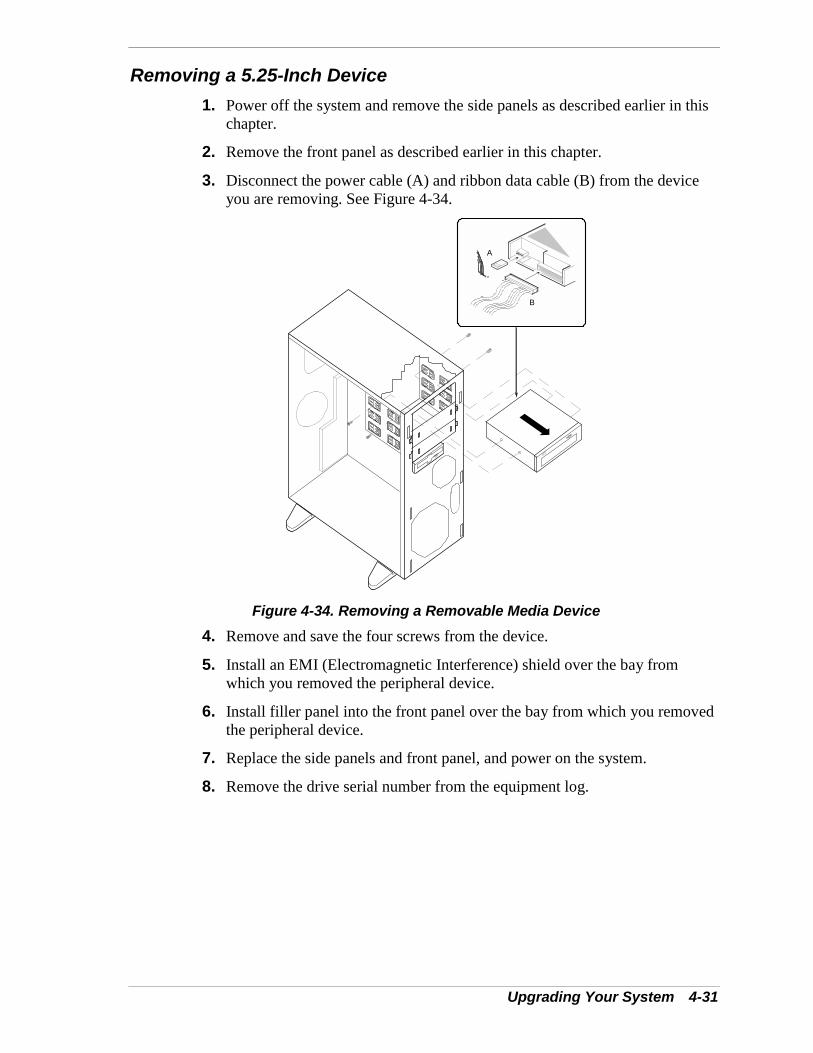
Upgrading Your System 4-31
Removing a 5.25-Inch Device1. Power off the system and remove the side panels as described earlier in this
chapter.
2. Remove the front panel as described earlier in this chapter.
3. Disconnect the power cable (A) and ribbon data cable (B) from the deviceyou are removing. See Figure 4-34.
A
B
Figure 4-34. Removing a Removable Media Device4. Remove and save the four screws from the device.
5. Install an EMI (Electromagnetic Interference) shield over the bay fromwhich you removed the peripheral device.
6. Install filler panel into the front panel over the bay from which you removedthe peripheral device.
7. Replace the side panels and front panel, and power on the system.
8. Remove the drive serial number from the equipment log.


5Problem Solving
! Problem Solving! Static Precautions! Troubleshooting Checklists! Diagnostic Testing! Specific Problems and Corrective Actions! Problems with the Network! Plug and Play Installation Tips! BIOS User’s Information! How to Identify BIOS Revision Level
5-2 Problem Solving
Problem SolvingThis chapter helps you identify and solve problems that may occur during systeminstallation or while using your system. The first section of this chapter tells you how toreset your system in the event of problems. The next few sections providetroubleshooting checklists and procedural steps that help you isolate specific systemproblems. The last section includes BIOS, system, and disk status user information.
! WARNINGThe DC push-button on/off switch on the front panel does not turn offthe system AC power. Also, +5vdc is present on the system boardwhenever the AC power cord is connected between the system andan AC outlet. Before doing the procedures in this manual, make surethat your system is powered off and unplug the AC power cords fromthe back of the chassis. Failure to disconnect power before openingyour system can result in personal injury and equipment damage
! CAUTIONOperating your system with the side panels removed can damageyour system components. For proper cooling and airflow, alwaysreplace the side panels before powering on your system.
Static PrecautionsAn electrostatic discharge (ESD) can damage disk drives, option boards, and othercomponents. You can provide some ESD protection by wearing an antistatic wrist strapattached to chassis ground when handling system components.
Electronic devices can be easily damaged by static electricity. To prevent damage, keepthem in their protective packaging when they are not installed in your system.
Problem Solving 5-3
Troubleshooting ChecklistsThe following subsections provide troubleshooting checklists for problems that occur atinitial system startup, when you run new application software, and after the systemhardware and software have been running correctly.
Initial System StartupIncorrect installation or configuration usually causes problems that occur at initialsystem startup. Hardware failure is a less frequent cause. If you have problems duringinitial system startup, check the following:
! Is the system power cord properly connected to the system and plugged into aNEMA 5-15R outlet (100-120 Vac) or a NEMA 6-15R outlet (200-240 Vac)?
! Is AC power available at the wall outlet?
! Is the power on/off push-button switch on the front panel in the ON position (poweron LED should be lit)?
! Are all cables correctly connected and secured?
! Are all the PCI option boards fully seated in their connector slots on the systemboard?
! Are all jumpers and switch settings on option boards and peripheral devices correct?If applicable, ensure that there are no conflicts; for example, two option boardssharing the same interrupt.
! Are all DIMMs fully seated and installed correctly? Refer to Chapter 4 forinstallation instructions?
! Are all option boards and disk drives installed correctly? Refer to the Chapter 4.
! Is the system hard disk drive properly formatted or defined?
! Is the operating system properly loaded? Refer to the operating systemdocumentation.
! Are all drivers properly installed? For information about installing drivers, refer toyour Network Operating System Configuration Guide.
! Are the configuration settings in BIOS Setup and the Adaptec SCSI Utility correct?For information about running these utilities, refer to the “Configuring YourSystem” chapter.
If the above items are all correct, but the problem reoccurs, refer to “AdditionalTroubleshooting Procedures” in this chapter.

5-4 Problem Solving
Running New Application SoftwareProblems that occur when you run new application software are usually related to thesoftware. Faulty equipment is much less likely, especially if other software runscorrectly. If you have problems while running new application software, check thefollowing:
! Does the system meet the minimum hardware requirements for the software? Referto the software documentation.
! Is the software an authorized copy? Unauthorized copies often do not work. Obtainan authorized copy of the software.
! If you are running the software from a diskette, is it a good copy?
! If you are running the software from a hard disk drive, is the software correctlyinstalled? Where all necessary procedures followed and files installed?
! If you are running the software from a CD-ROM disk is the disk scratched or dirty?
! Are the correct device drivers installed?
! Is the software correctly configured for the system?
! Are you using the software correctly?
! If other software runs correctly on the system, contact your vendor about the failingsoftware.
If the problems persist with the software, contact the software vendor's customer servicerepresentative.
Problem Solving 5-5
After System Has Been Running CorrectlyProblems that occur after the system hardware and software have been runningcorrectly often indicate equipment failure. However, many situations that are easy tocorrect can also cause such problems. If you have problems after the system has beenrunning correctly, check the following:
! If you are running the software from a diskette or CD-ROM, try a new copy of thesoftware.
! If you are running the software from a hard disk drive, try running it from a floppy.If the software runs correctly, there may be a problem with the copy on the harddisk. Reinstall the software on the hard disk drive and try running it again. Makesure all the necessary files are installed.
! If the problem recurs, you may need to reformat the hard disk drive. The hard diskdrive, the drive controller, or the system board may be defective.
! If the problems are intermittent, there may be a loose cable, dirt in the keyboard (ifkeyboard input is incorrect), a marginal power supply, or other random componentfailures.
! If you suspect that a transient voltage spike, power outage, or brownout might haveoccurred, reload the software and try running it again. Symptoms of voltage spikesinclude a flickering video display, unexpected system reboots, and the system notresponding to user commands.
Note: Voltage spikes can corrupt or destroy data files on thedrive. If you are experiencing voltage spikes on the power line, installa surge suppresser between the power outlet and the system powercord.
If the problem recurs after you have checked and corrected all of the above items, referto “Diagnostic Testing” in this chapter.
5-6 Problem Solving
Diagnostic TestingThis section provides a more detailed approach to diagnostic testing and identificationof a problem and locating its source.
Error CheckingEach time you turn on the system, POST (Power-On-Self-Test) runs automatically andchecks the system boards, processors, memory, keyboard, and most installed peripheraldevices.
If POST finds an error, it displays an error message. Refer to the Error Message sectionin this chapter for an explanation of each error message.
Troubleshooting GuideUse the following troubleshooting procedures to help you identify a problem. Thesegeneral procedures lead you through the following:
! Preparing the system for diagnostic testing
! Monitoring POST while it is running
! Verifying proper operation of key system LEDs
! Confirming loading of the operating system.
Preparing the System for Diagnostic Testing
To prepare the system for diagnostic testing, perform the following:
Note: Before disconnecting any peripheral cables from thesystem, turn off the system and any external peripheral devices.Failure to do so can cause permanent damage to the system and/orthe peripheral devices.
1. Turn off the system and all external peripheral devices. Disconnect all devices fromthe system except the keyboard and video monitor.
2. Make sure the system power cord is plugged into a properly grounded AC outlet.
3. Make sure your video display monitor and keyboard are correctly connected to thesystem. Turn on the video monitor. Set its brightness and contrast controls to at leasttwo-thirds of their maximum ranges (refer to the documentation supplied with yourvideo display monitor).
4. If the operating system normally loads from the hard disk drive, make sure there isno diskette in drive A. Otherwise, place a diskette containing the operating systemfiles in drive A.
5. Turn on the system. If the power indicator LED does not light, refer to “PowerLight Does Not Light” found later in this chapter.

Problem Solving 5-7
Monitoring POST
Each time you turn on the system, the Power-On Self-Test (POST) runs automaticallyand checks the system board, processor board, memory, keyboard, and most installedperipheral devices.
During the memory test, POST displays the amount of memory that it is able to accessand test. Depending on the amount of memory, it may take several minutes to completethe memory test.
Press F2 to enter SETUP. If you do not press F2, the above message remains for a fewseconds and the boot process continues.
If POST finds an error, it displays an error message and, in case there is a problem withthe display, it emits a series of long and short beeps. Write down any beep codeemitted. This information is useful to your service representative.
Refer to the “BIOS User’s Information” section in this chapter for a list of items tocheck for each error code and for an explanation of the error beep codes.
The POST Tests table at the end of this chapter lists keys active during POST andprovides a description of errors that may occur.
The BIOS indicates errors by writing an error code to the PS/2-standard logging area inthe Extended BIOS Data Area, and by displaying a message on the screen, which issometimes preceded by the POST Error Code. The error code will also be logged to theEvent Logging area.
Report any error code to your service representative.
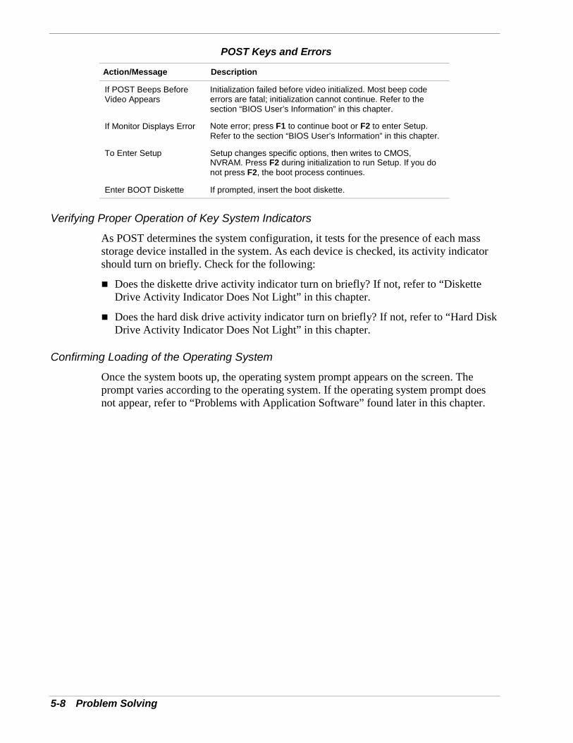
5-8 Problem Solving
POST Keys and Errors
Action/Message Description
If POST Beeps BeforeVideo Appears
Initialization failed before video initialized. Most beep codeerrors are fatal; initialization cannot continue. Refer to thesection “BIOS User’s Information” in this chapter.
If Monitor Displays Error Note error; press F1 to continue boot or F2 to enter Setup.Refer to the section “BIOS User’s Information” in this chapter.
To Enter Setup Setup changes specific options, then writes to CMOS,NVRAM. Press F2 during initialization to run Setup. If you donot press F2, the boot process continues.
Enter BOOT Diskette If prompted, insert the boot diskette.
Verifying Proper Operation of Key System Indicators
As POST determines the system configuration, it tests for the presence of each massstorage device installed in the system. As each device is checked, its activity indicatorshould turn on briefly. Check for the following:
! Does the diskette drive activity indicator turn on briefly? If not, refer to “DisketteDrive Activity Indicator Does Not Light” in this chapter.
! Does the hard disk drive activity indicator turn on briefly? If not, refer to “Hard DiskDrive Activity Indicator Does Not Light” in this chapter.
Confirming Loading of the Operating System
Once the system boots up, the operating system prompt appears on the screen. Theprompt varies according to the operating system. If the operating system prompt doesnot appear, refer to “Problems with Application Software” found later in this chapter.
Problem Solving 5-9
Specific Problems and Corrective ActionsThis section provides possible solutions for the following specific problems:
! Power LED does not light
! No beep or incorrect beep pattern
! No characters appear on screen
! Characters on the screen appear distorted or incorrect
! System cooling fan does not rotate
! Diskette drive activity LED does not light
! Hard disk drive activity LED does not light
! CD-ROM drive activity LED does not light
! Problems with application software
! The startup prompt “Press <F2> key if you want to run Setup” does not appear onthe screen.
! The bootable CD-ROM is not detected.
Try the solutions in the order given. If you cannot correct the problem, contact yourservice representative for assistance.
Power LED Does Not LightCheck the following:
! Is the system operating normally? If so, the power LED is probably defective.
! Are there other problems with the system? If so, check the items listed under SystemCooling Fans Do Not Rotate.

5-10 Problem Solving
Incorrect or No Beep CodeIf the system operates normally, but there was no beep, the piezo buzzer located on thesystem board, may be defective. Contact your service representative for assistance.
Record the beep code emitted by POST, and see the “Messages and Beep Codes”section found later in this chapter.
No Characters Appear on ScreenCheck the following:
! Is the keyboard working? Check to see if the Num Lock light is functioning.
! Is the video display monitor plugged in and turned on?
! Are the brightness and contrast controls on the video monitor properly adjusted?
! Are the video monitor switch settings correct?
! Is the video monitor signal cable properly installed?
! Is the onboard video controller enabled?
If you are using a video controller board, verify that the video controller board is fullyseated in the system board connector.
If there are still no characters on the screen after you reboot the system, contact yourservice representative or authorized dealer for assistance.
POST emits one long beep and two short beeps pattern to indicate a possible problemwith the video display controller. If you do not receive a beep pattern and characters donot display, the video display or video controller may have failed. Contact your servicerepresentative or authorized dealer for assistance.

Problem Solving 5-11
Characters are Distorted or IncorrectCheck the following:
! Are the brightness and contrast controls properly adjusted on the video display?Refer to the documentation supplied with your video display.
! Are the video monitor's signal and power cables properly installed?
! If the problem persists, the video monitor may be faulty or it may be the incorrecttype. Contact your service representative for assistance.
System Cooling Fans Do Not RotateCheck the following:
! Is AC power available at the wall outlet?
! Are the system power cords properly connected to the power supplies and the ACwall outlets?
! Are the power connectors for the cooling fans connected?
! Is the front panel power on indicator lit?
If the switches and connections are correct and the power outlet is functioning, thepower supply has probably failed. Contact your service representative for assistance.
Diskette Drive Activity LED Does Not LightCheck the following:! Is the diskette drive's combined power and signal cables properly installed?
! Is the diskette drive properly configured?
! Is the diskette drive activity light always on? If so, the signal cable may be pluggedin incorrectly.
If you are using the onboard diskette drive controller, use BIOS Setup to make sure thatthe diskette drive controller is set to Enabled. For information about running BIOSSetup, refer to the “Configuring Your System” chapter.If the problem persists, there may be a problem with the diskette drive, system board, ordrive signal cable. Contact your service representative for assistance.
CD-ROM Drive Activity Light Does Not LightCheck the following:
! Is the power and signal cable to the CD-ROM drive properly installed?
! Are all relevant switches and jumpers on the drive set correctly?
! Is the drive properly configured?
! Is the onboard IDE controller enabled?
5-12 Problem Solving
Problems with Application SoftwareIf you have problems with application software, perform the following:
! Verify that the software is properly configured for the system. Refer to the softwareinstallation and operation documentation for instructions on setting up and using thesoftware.
! Verify a different copy of the software to see if the problem is with the copy that youare using.
! Make sure all cables are installed correctly.
! Verify that the system board jumpers are set correctly. Refer to the “ConfiguringYour System” chapter for jumper settings.
! If other software runs correctly on the system, contact your vendor about the failingsoftware.
If the problem persists, contact the software vendor's customer service representativefor assistance.
Bootable CD-ROM Is Not DetectedCheck the following:
! Is the BIOS set to allow the CD-ROM to be the second bootable device? Check yourBIOS Setup (F2) configuration.
Problems with the NetworkDiagnostics pass, but the connection fails:
! Make sure the network cable is securely attached. ACT/Link activity LED located onthe front panel should be blinking if there is activity between the system and thenetwork.
The controller stopped working when an add-in adapter was installed:
! Make sure the cable is connected to the port from the onboard network controller.
! Make sure the other adapter supports shared interrupts. Also, make sure youroperating system supports shared interrupts; OS/2 does not.
! Try reseating the add-in adapter.
The add-in adapter stopped working without apparent cause.
! Try reseating the adapter first; then try a different slot if necessary.
! The network driver files may be corrupt or deleted. Delete and then reinstall thedrivers.
! Run the diagnostics.
Problem Solving 5-13
Plug and Play Installation TipsSome common PCI tips are listed here.
! Reserve interrupts (IRQs) and/or memory addresses specifically for an ISA adapter.This prevents PCI cards from trying to use the same settings an ISA card is using.Use the BIOS Setup Utility to keep track of ISA adapter resources.
! Certain drivers may require interrupts that are not shared with other PCI drivers.The BIOS Setup Utility can be used to adjust the interrupt numbers for PCI devices.For certain drivers, it may be necessary to alter settings so that interrupts are notshared.
BIOS User’s InformationThis section describes the various screen messages and beep codes of the system BIOS.The BIOS indicates errors by writing an error code to the PS/2-standard logging area inthe Extended BIOS Data Area, and by displaying a message on the screen, which issometimes preceded by the POST Error Code. The error code will also be logged to theEvent Logging area.
Note: Your system error log will be lost, if your system ac powersource is off or disconnected.

5-14 Problem Solving
POST Error Codes and MessagesWhenever a recoverable error occurs during POST, BIOS displays a message on thevideo display screen and causes the speaker to beep as the message appears. BIOS alsoissues a beep code (one long tone followed by two short tones) during POST if thevideo configuration fails or if an external ROM module does not a checksum of zero.The “POST Error Codes and Messages” table is a list of the possible error codes andmessages written at the start of each POST test. The “POST Error Beep Codes” table isa list of beep codes issued for each POST test. Figure 5-1 shows the location of specificcomponents referenced in the POST Error Codes and Messages Table.
Table 5-1. POST Error Codes and MessagesError code Error message Recommended Action0200 Failure Fixed Disk Contact your service representative.
0210 Stuck Key Disconnect the keyboard and connect it again.
0211 Keyboard error
0212 Keyboard Controller Failed
Disconnect the keyboard and connect it again.
Restart the system.
If the error cannot be corrected, contact your service representative.
0213 Keyboard locked - Unlock keyswitch.
Release the lock of the key switch. If the error cannot be corrected in spite ofthe release of the lock, contact your service representative.
0220 Monitor type does not matchCMOS - Run SETUP.
Start the SETUP. If the error cannot be corrected in spite of the start ofSETUP, contact your service representative.
0230 System RAM Failed at offset.
0231 Shadow Ram Failed at offset.
0232 Extended RAM Failed at addressline.
Contact your service representative.
0233 Memory type mixing detected Install the memory specified by NEC.
0234 Single-bit ECC error
0235 Multiple-bit ECC error occurred
Contact your service representative.
0250 System battery is dead - Replaceand run SETUP.
Contact your service representative to replace the battery. (After restarting thecomputer, start the SETUP to provide the setting again.)
0251 System CMOS checksum bad -Default configuration used.
The default values have just been set. Start the SETUP to provide the settingagain.
0260 System timer error.
0270 Real time clock error.
Contact your service representative.
0271 Check date and time setting Start the SETUP to set the date and time again. If the same error occurssuccessively in spite of the resetting, contact your service representative.
02B0 Diskette drive A error. Contact your service representative.
02B2 Incorrect Drive A type - runSETUP.
Start the SETUP to provide the setting again.
02D0 System cache error - Cachedisabled.
The cache cannot be used. Contact your service representative.
0B1B PCI System Error onBus/Device/Function.
Contact your service representative.
Problem Solving 5-15
Table 5-1. POST Error Codes and Messages (Continued)Error code Error message Recommended Action0B1C PCI Parity Error on
Bus/Device/Function.
0B30 Fan 1 Alarm occurred.
0B31 Fan 2 Alarm occurred.
A fan failure or fan clogging may occur. Contact your servicerepresentative to request the maintenance.
0B22 Expansion Rom not initialized Check the PCI board installation. Or, disable the PCI board settingnot needed at start-up in [Advanced] → [Option ROM] of the SETUPutility.
NOTES:
Do not disable the PCI device connected to the hard disk containingthe OS.
Do not disable the graphics device to which the monitor is connected.
Disable the Option ROM of PCI LAN device when network bootfeature is not used.
If the error persists, contact your sales representative to replace thePCI board.
0B50 CPU #1 with error taken offline.
0B51 CPU #2 with error takenoffline.
The CPU is degraded. Contact your service representative.
0B5F Forced to use CPU with error Because an error is detected in every CPU, the system is forciblystarted. Contact your service representative.
0B60 DIMM group #1 has beendisabled
0B61 DIMM group #2 has beendisabled
0B62 DIMM group #3 has beendisabled
0B63 DIMM group #4 has beendisabled
Contact your service representative.
0B6F DIMM group with error isenabled
Because an error is detected in every DIMM, the system is forciblystarted. Contact your service representative.
0B70 The error occurred duringtemperature sensor reading.
Contact your service representative.
0B71 System Temperature out of therange.
A fan failure or fan clogging may occur. Contact your servicerepresentative to request the maintenance.
0B72 The error occurred duringvoltage sensor reading.
0B75 System voltage out of therange.
0B7C The error occurred during fansensor reading
Contact your service representative.
5-16 Problem Solving
Table 5-1. POST Error Codes and Messages (ContinuedError code Error message Recommended Action0BB0 SMBIOS - SROM data read
error.
0BB1 SMBIOS - SROM datachecksum bad.
Contact your service representative.
0BD0 1st SMBus device address notacknowledged.
0BD1 1st SMBus device Errordetected.
0BD2 1st SMBus timeout.
Not a fatal error.
Turn off the power and then restart the server.
If an error persists, contact your service representative.
RomPilot reports error numberxx
Turn off the power and then restart the server.
Or, start SETUP to verify the settings.
If an error persists, contact your service representative.
Expansion Rom not initialized Change settings in [Advanced] → [Option ROM] of SETUP utility.
Invalid System ConfigurationData
System Configuration DataRead Error
Resource Conflict
System Configuration DataWrite Error
0C00
WARNING: IRQ not configured
Contact your service representative.
DIMM#4DIMM#3DIMM#2DIMM#1
CPU#1
CPU#2
Figure 5-1. Component Locations
Problem Solving 5-17
How to Identify BIOS Revision LevelTo help you identify your system's current BIOS revision level, refer to the followingsubsections.
BIOS Revision Level IdentificationDuring system Power-On Self Test (POST), which runs automatically when yoursystem is powered on, your system monitor displays several messages, one of whichidentifies the BIOS revision level currently loaded on your system, see the examplebelow.
Note: In order to see the diagnostic messages, the ESC keymust be pressed.
Example: BIOS Revision LevelPhoenix BIOS 4.0 Release 6.0.250A
In the example above, BIOS 6.0.250A is the current BIOS revision level loaded on yoursystem.
Note: The BIOS Revision Level stated in the example may notreflect the actual BIOS setting in your system.

5-18 Problem Solving

ASystem Cabling
! System Cabling! Before You Begin! Static Precautions! Standard Configuration
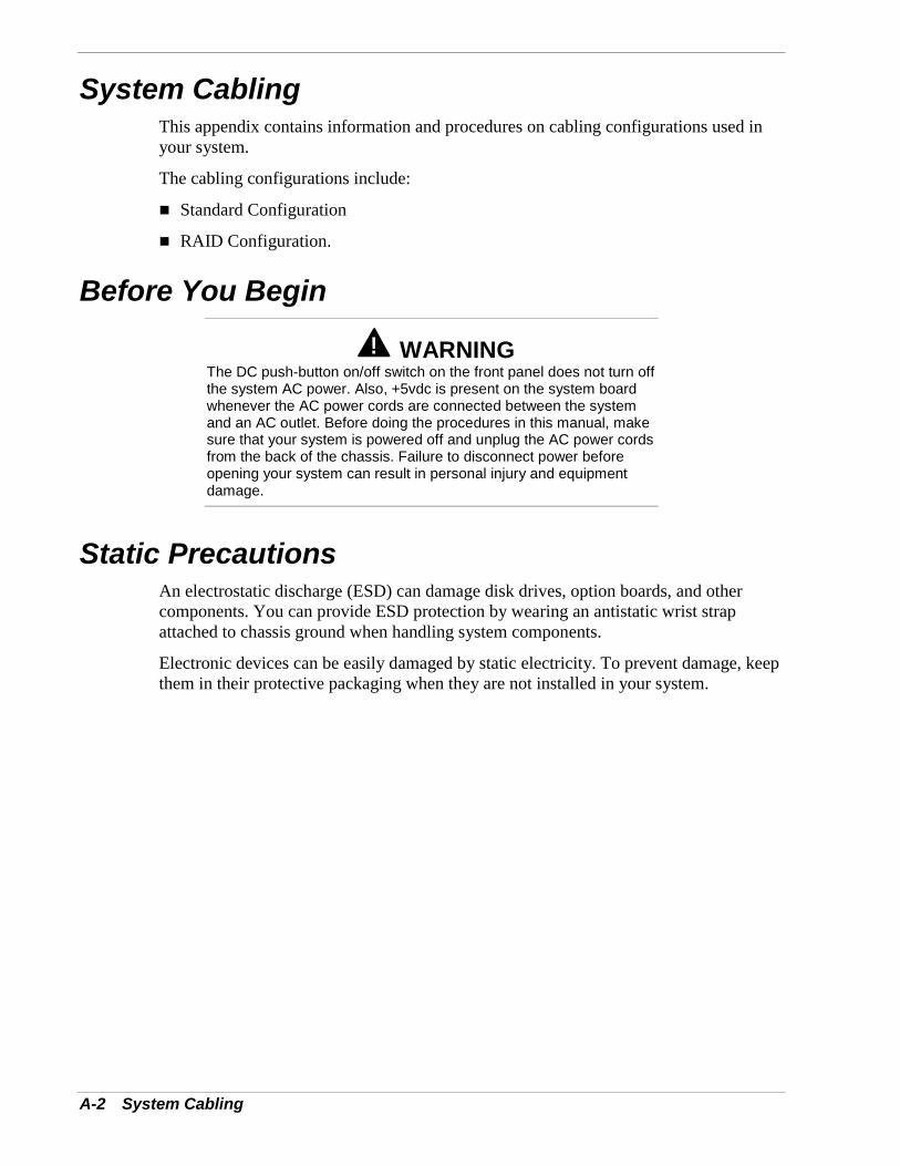
A-2 System Cabling
System CablingThis appendix contains information and procedures on cabling configurations used inyour system.
The cabling configurations include:
! Standard Configuration
! RAID Configuration.
Before You Begin
! WARNINGThe DC push-button on/off switch on the front panel does not turn offthe system AC power. Also, +5vdc is present on the system boardwhenever the AC power cords are connected between the systemand an AC outlet. Before doing the procedures in this manual, makesure that your system is powered off and unplug the AC power cordsfrom the back of the chassis. Failure to disconnect power beforeopening your system can result in personal injury and equipmentdamage.
Static PrecautionsAn electrostatic discharge (ESD) can damage disk drives, option boards, and othercomponents. You can provide ESD protection by wearing an antistatic wrist strapattached to chassis ground when handling system components.
Electronic devices can be easily damaged by static electricity. To prevent damage, keepthem in their protective packaging when they are not installed in your system.
System Cabling A-3
Standard ConfigurationYour system is cabled using a dual channel on-board IDE Controller.
The on-board IDE controller supports two IDE hard disk drives on the primary IDEchannel and the standard internally mounted CD-ROM drive on the secondary IDEchannel. An additional IDE device may be connected to the secondary IDE channel.
A 3.5-inch diskette drive is also installed in all systems and interfaces separately to thesystem board.
Figure A-1 illustrates the standard system configuration. The IDE interface cable (C) isconnected from the diskette drive IDE connector to the diskette drive (D). The primaryIDE interface cable (E) connects from the primary interface connector to the hard diskdrives (F). And the secondary IDE interface cable (G) connects from the secondaryinterface connector to the rear of the internally mounted CD-ROM drive (H).
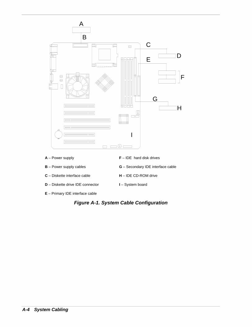
A-4 System Cabling
A
BC
DE
F
GH
I
A – Power supply F – IDE hard disk drives
B – Power supply cables G – Secondary IDE interface cable
C – Diskette interface cable H – IDE CD-ROM drive
D – Diskette drive IDE connector I – System board
E – Primary IDE interface cable
Figure A-1. System Cable Configuration

BSpecifications
! System Specifications
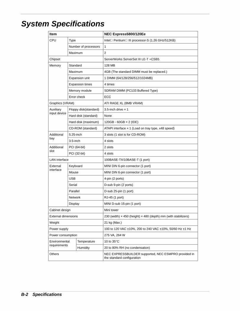
B-2 Specifications
System SpecificationsItem NEC Express5800/120Ee
Type Intel Pentium III processor-S (1.26 GHz/512KB)
Number of processors 1
CPU
Maximum 2
Chipset ServerWorks ServerSet III LE-T +CSB5
Standard 128 MB
Maximum 4GB (The standard DIMM must be replaced.)
Expansion unit 1 DIMM (64/128/256/512/1024MB)
Expansion times 4 times
Memory module SDRAM DIMM (PC133 Buffered Type)
Memory
Error check ECC
Graphics (VRAM) ATI RAGE XL (8MB VRAM)
Floppy disk(standard) 3.5-inch drive × 1
Hard disk (standard) None
Hard disk (maximum) 120GB - 60GB × 2 (IDE)
Auxiliaryinput device
CD-ROM (standard) ATAPI interface × 1 (Load on tray type, x48 speed)
5.25-inch 3 slots (1 slot is for CD-ROM)Additionalbay
3.5-inch 4 slots
PCI (64-bit) 2 slotsAdditionalslot
PCI (32-bit) 4 slots
LAN interface 100BASE-TX/10BASE-T (1 port)
Keyboard MINI DIN 6-pin connector (1 port)
Mouse MINI DIN 6-pin connector (1 port)
USB 4-pin (2 ports)
Serial D-sub 9-pin (2 ports)
Parallel D-sub 25-pin (1 port)
Network RJ-45 (1 port)
Externalinterface
Display MINI D-sub 15-pin (1 port)
Cabinet design Mini tower
External dimensions 230 (width) × 450 (height) × 480 (depth) mm (with stabilizers)
Weight 21 kg (Max.)
Power supply 100 to 120 VAC ±10%, 200 to 240 VAC ±10%, 50/60 Hz ±1 Hz
Power consumption 275 VA, 264 W
Temperature 10 to 35°CEnvironmentalrequirements
Humidity 20 to 80% RH (no condensation)
Others NEC EXPRESSBUILDER supported, NEC ESMPRO provided inthe standard configuration
CInstalling and Configuring Windows2000 and Windows NT 4.0
C-2 Installing and Configuring Windows 2000 and Windows NT 4.0
Windows 2000The EXPRESSBUILDER “Express Setup” feature provides an automated installationprocedure for Windows 2000. Refer to the EXPRESSBUILDER User’s Guide includedon the EXPRESSBUILDER CDROM for information on running “Express Setup.”
This section of Appendix C contains instructions needed to manually install andconfigure hardware and software used with the Microsoft Windows® 2000 OperatingSystem. This information is intended to supplement the more detailed proceduraldocuments available from Microsoft. This information is not intended to be the centralsource of installation and configuration information for your system. Read this entireappendix along with Microsoft's Windows® 2000 Setup procedures before starting theinstallation process.
Note: Read the System Release Notes for the latest systeminformation before attempting to install Windows 2000 OperatingSystem on your system.
Device DriversThe drivers required for the devices listed in the table below are located on theEXPRESSBUILDER CD that is included with your system. To create the requireddiskettes, select “Tools” on the EXPRESSBUILDER CD menu.
Note: When creating the required diskettes from theEXPRESSBUILDER CD make sure you use the drivers required forthe devices on your specific system.
Always read the information in the release notes or inserts, includedwith any options for they supersede the information in this guide.
Supported Device Required Driver Media*
SCSI RAIDController
Windows 2000 OEM Diskette*
System Board Windows 2000 NEC Update Module**
*Diskette generated from the NEC EXPRESSBUILDER CDROM **Run this application from the EXPRESSBUILDER CDROM; diskette not required
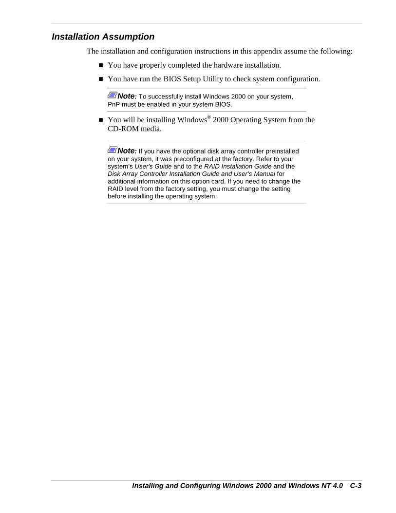
Installing and Configuring Windows 2000 and Windows NT 4.0 C-3
Installation AssumptionThe installation and configuration instructions in this appendix assume the following:
! You have properly completed the hardware installation.
! You have run the BIOS Setup Utility to check system configuration.
Note: To successfully install Windows 2000 on your system,PnP must be enabled in your system BIOS.
! You will be installing Windows® 2000 Operating System from theCD-ROM media.
Note: If you have the optional disk array controller preinstalledon your system, it was preconfigured at the factory. Refer to yoursystem's User's Guide and to the RAID Installation Guide and theDisk Array Controller Installation Guide and User’s Manual foradditional information on this option card. If you need to change theRAID level from the factory setting, you must change the settingbefore installing the operating system.
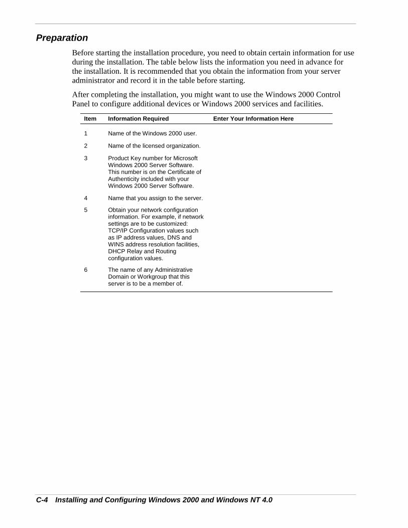
C-4 Installing and Configuring Windows 2000 and Windows NT 4.0
PreparationBefore starting the installation procedure, you need to obtain certain information for useduring the installation. The table below lists the information you need in advance forthe installation. It is recommended that you obtain the information from your serveradministrator and record it in the table before starting.
After completing the installation, you might want to use the Windows 2000 ControlPanel to configure additional devices or Windows 2000 services and facilities.
Item Information Required Enter Your Information Here
1 Name of the Windows 2000 user.
2 Name of the licensed organization.
3 Product Key number for MicrosoftWindows 2000 Server Software.This number is on the Certificate ofAuthenticity included with yourWindows 2000 Server Software.
4 Name that you assign to the server.
5 Obtain your network configurationinformation. For example, if networksettings are to be customized:TCP/IP Configuration values suchas IP address values, DNS andWINS address resolution facilities,DHCP Relay and Routingconfiguration values.
6 The name of any AdministrativeDomain or Workgroup that thisserver is to be a member of.
Installing and Configuring Windows 2000 and Windows NT 4.0 C-5
Installing Microsoft Windows® 2000 Operating SystemUse the following procedure to set up and perform a clean Windows 2000 OperatingSystem installation on your server.
1. Insert the Windows 2000 CD into the CD-ROM drive and boot your system bypressing CTRL+ALT+Delete.
Note: Perform Steps 2 through 6 if a RAID or SCSI controller isinstalled in your server; go to Step 7 if your server does not include aRAID or SCSI controller.
2. While the message “Setup is inspecting your computer’s hardware configuration” ora solid blue background is displayed on the screen, press the F6 key.
Note: There is no visible indication on the screen when the F6key has been pressed.
3. When the following message is displayed, press S.
“Setup could not determine the type of one or more mass storage devices installedin your system, or you have chosen to manually specify an adapter”. Currently,Setup will load support for the following mass storage devices.
4. When the following message is displayed, select “Other” and then press Enter.
Select the SCSI Adapter your want from the following list, or select "Other" if youhave a device support disk provided by an adapter manufacturer
5. Insert the "Windows 2000 OEM-DISK" diskette into the floppy drive, and pressEnter. A list of mass storage devices is displayed.
6. Select the SCSI or RAID disk array controller installed in your server from the listof mass storage devices.
7. Follow the messages on the screen to continue to install.
Note: Please consult the Microsoft Windows 2000 InstallationGuide for more extensive installation procedures.
For LAN adapter driver installation, see Installing LAN AdapterDrivers later in this appendix.
8. After installing Windows 2000, logon to the system using the administrator accountor other account, which is a member of the Administrator’s group.
C-6 Installing and Configuring Windows 2000 and Windows NT 4.0
9. Insert the EXPRESSBUILDER CD into the CDROM drive. The START menudisplays.
10. Select “Drivers and Utilities” from the START menu.
11. Select 120Ee.
12. Select and run the “Windows 2000 NEC Update Module” for the Express5800120Ee Server.
Note: If you change the configuration of the system (by addingor removing hardware or operating system software components), orrepair the system, you must run the Windows 2000 NEC UpdateModule again.
Installing LAN AdaptersThe following section includes special driver installation instructions for the IntelPRO/100+ LAN adapter used in your system.
Driver Installation for the Intel PRO/100+ LAN Adapter
The PRO/100+ driver is initially installed during the installation of Windows 2000 andupgraded when you run the “Windows 2000 NEC Update Module, see “InstallingMicrosoft Windows® 2000 Operating System” found earlier in this appendix. In orderto utilize the PRO/100+ LAN adapter “teaming features,” diagnostic features, ordetailed adapter information, use the following procedure to install “PROSET II forWindows 2000.”
1. Power on, start Windows 2000, and log on.
2. Insert the EXPRESSBUILDER CD into the CDROM drive. The “Start” Menudisplays.
3. Select “Drivers & Utilities” from the “Start” Menu.
4. Select INTEL.
5. Select and run “PROSET II for Windows 2000.”
Driver Installation for the ATI RAGE XL Display AdapterTo take full advantage of the on-board ATI RAGE XL display adapter, perform thefollowing driver installation procedure:
1. Power on, start Windows 2000, and log on.
2. Insert the EXPRESSBUILDER CD into the CDROM drive. The “Start” Menudisplays.
3. Select “Drivers & Utilities” from the “Start” Menu.
4. Select ATI.
5. Select and run “Rage XL Driver for Windows 2000.”
Installing and Configuring Windows 2000 and Windows NT 4.0 C-7
Windows NT 4.0The EXPRESSBUILDER “Express Setup” feature provides an automated installationprocedure for Windows NT 4.0. Refer to the EXPRESSBUILDER User’s Guideincluded on the EXPRESSBUILDER CDROM for information on running “ExpressSetup.”
This section of Appendix C contains instructions needed to manually install andconfigure hardware and software used with the Microsoft Operating System WindowsNT Release 4.0. This information is intended to supplement the more detailedprocedural documents available from Microsoft. This information is not intended to bethe central source of installation and configuration information for your system. Readthis entire appendix along with Microsoft's Windows NT 4.0 installation proceduresbefore starting the installation process.
Note: Read the System Release Notes for the latest systeminformation before attempting to install Windows NT 4.0 OperatingSystem on your system.
Device DriversThe drivers required for the devices listed in the table below are located on theEXPRESSBUILDER CD. To create the required diskettes, select “Tools” on theEXPRESSBUILDER CD. This table lists the required diskette labels.
Note: When creating the required diskettes from the EXPRESSBUILDER CDmake sure you use the drivers required for the devices on your specific system.
Always read the information in the release notes or inserts, included with anyoptions for they supersede the information in this guide.
Device Required Driver Media*
SCSI or SCSI RAID Controller Windows NT 4.0 OEM - Disk #1*
Network Controller Windows NT 4.0 OEM - Disk #2*
System Board Windows NT 4.0 NEC Update Module**
Video RAGE XL Driver for Windows NT 4.0**
*Diskette generated from the NEC EXPRESSBUILDER CDROM**Run this application from the EXPRESSBUILDER CDROM; diskette not required
C-8 Installing and Configuring Windows 2000 and Windows NT 4.0
Configuring RAIDIf you have a Disk Array Controller preinstalled on your system, it was preconfigured atthe factory. Refer to your system's User's Guide and to the AcceleRAID InstallationGuide and the Disk Array Controller Installation Guide and User’s Manual foradditional information on this option card. If you need to change the RAID level fromthe factory setting, you must change the setting before installing the operating system.
Installing Microsoft Windows® NT 4.0 Operating SystemUse this procedure to install Windows NT 4.0 Operating System.
1. Insert the Windows NT CD into the CD-ROM drive and boot your system bypowering on the system.
Note: Perform Steps 2 through 6 if a RAID or SCSI controller isinstalled in your server; go to Step 7 if your server does not include aRAID or SCSI controller.
2. While the message “Setup is inspecting your computer’s hardware configuration” ora solid blue background is being displayed on the screen, press the F6 key.
Note: There is no visible indication on the screen when the F6key has been pressed.
3. When the following message is displayed, press S.
“Setup could not determine the type of one or more mass storage devices installedin your system, or you have chosen to manually specify an adapter”. Currently,Setup will load support for the following mass storage devices.
4. When the following message is displayed, select “Other,” then press Enter.
Select the SCSI Adapter your want from the list, or select "Other" if you have adevice support disk provided by an adapter manufacturer
5. Insert the "Windows NT 4.0 OEM-DISK #1" diskette into the floppy drive, andpress Enter. A list of mass storage devices is displayed.
6. If you are using a SCSI or disk array controller, select the appropriate "devicecontroller" from the above list of mass storage devices.
7. Follow the message on the screen to continue to install the operating system.
Note: Please consult the Microsoft Windows NT 4.0 InstallationGuide for more extensive installation procedures.
Note: For LAN adapter driver installation, see Installing LANAdapter Drivers later in this appendix.
Installing and Configuring Windows 2000 and Windows NT 4.0 C-9
8. After installing Windows NT, logon to the system using the administrator accountor other account, which is a member of the Administrators group.
9. Insert the EXPRESSBUILDER CD into the CDROM drive. The START menudisplays.
10. Select “Drivers and Utilities” from the START menu.
11. Select 120Ee.
12. Select and run the “Windows NT 4.0 NEC Update Module” for the Express5800120Ee Server.
Note: If you change the configuration of the system (by addingor removing hardware or operating system software components), orrepair the system, you must run the system update again.
Installing LAN Adapter DriversThe following section includes special driver installation instructions for LAN adaptersused in your system.
Driver Installation for the Intel PRO/100+ LAN Adapter
The PRO/100+ driver will be installed during the installation of Windows NT, see“Installing Microsoft Windows® NT 4.0 Operating System” earlier in this appendix.
Use the following procedure to install the LAN adapter driver on your server:
1. During the Windows NT installation when the dialog box displaying the message"To have setup search for a Network Adapter, click Start Search button" opens.Click “Select from List”.
2. In the “Select Network Adapter” dialog box 1, Click “Have Disk”. The "InsertDisk" dialog box opens.
3. Insert the floppy disk named "Windows NT 4.0 OEM-DISK #2" into the floppydisk drive.
4. Enter "A:\RS503C" and click on [OK].
5. The "Select OEM Option" dialog box opens.Select "Intel(R) PRO Adapter" and click on [OK].
6. Click on [NEXT].
7. You may need to specify network information depending on the protocol you use.Follow the message on the screen to continue the Windows NT installation.

C-10 Installing and Configuring Windows 2000 and Windows NT 4.0
Driver Installation for the ATI RAGE XLDisplay Adapter
To take full advantage of the on-board ATI RAGE XL display adapter, perform thefollowing driver installation procedure:
1. Power on, start Windows NT, and log on.
2. Insert the EXPRESSBUILDER CD into the CDROM drive. The “Start” Menudisplays.
3. Select “Drivers & Utilities” from the “Start” Menu.
4. Select ATI.
5. Select and run “Rage XL Driver for Windows NT."
Glossary 1
GlossaryA AC(Alternating Current) The type of current available in wall outlets. All computers mustconvert alternating current to direct current to operate. See also DC.
ACPI(Advanced Configuration and Power Interface) Provides the programming standard forpower management features.
addressA label, name, or number that identifies a location in computer memory.
AGPAccelerated Graphics Port.
ASCII(American Standard Code for Information Interchange) A standard number assigned to eachof the alphanumeric characters and keyboard control code keys to enable the transfer ofinformation between different types of computers and peripherals.
B backplane slotA connector on the backplane board in desktop computers and expansion boxes that allowsyou to install circuit cards.
backupA copy of data for safe-keeping. The data is copied from computer memory or disk to afloppy disk, magnetic tape, or other media.
backup batteryThe battery in your computer that maintains the real-time clock and the configurationinformation when the computer's power is removed.
base memoryAn area of memory between 0 and 640 kilobytes.
baud rateThe speed with which data is transmitted during serial communication. The computer'soperating system and software program must be configured for the same baud rate as thecommunication device, such as a serial printer. See also bps.
BIOS(Basic Input/Output System) A program stored in flash EPROM or ROM that controls thekeyboard, disk drives, video monitor, and other devices. See also flash EPROM, EPROM,and ROM.

2 Glossary
bitDerived from BInary digiT, a bit is the smallest unit of information a computer handles. Seealso byte.
BMC(Baseboard Management Controller) Contains all of the server management functions. Onemajor function of the BMC is to monitor system management events and log theiroccurrence in the System Event Log (SEL).
bootThe process of loading the operating system into memory.
bps(bits per second) The number of bits transferred in one second during serial communication,such as modem transmission.
byteA group of eight bits.
C cache memoryA very fast, limited portion of RAM set aside for temporary storage of data for direct accessby the microprocessor.
CD-ROM drive(Compact Disk ROM drive) A type of mass storage device that reads information from acompact disk.
Centronics portAn industry standard parallel port. See also parallel port.
CGA(Color Graphics Adapter) A type of video display system that provides low-resolution textand graphics on TTL monochrome and color monitors.
CMOS(Complimentary Metal-Oxide Semiconductor) A type of low-power integrated circuit usedin computers. See also TTL.
COM1 or COM2The name you can assign a serial port to set or change its address. See also serial port.
commandAn instruction that directs the computer to perform a particular operation.
configurationThe way in which a computer is set up to operate. Some configurable options include CPUspeed, serial port designation, and memory allocation.
Glossary 3
CPU(Central Processing Unit) See microprocessor.
CRT(Cathode-Ray Tube) The type of video display used in monitors for desktop computers.
D DC(Direct Current) The type of current available in the rechargeable battery packs used inportable computers. See also AC.
defaultThe factory setting your computer uses unless you instruct it otherwise. For example, whenpowering up, the computer will boot from the default drive.
densityThe capacity of information (bytes) that can be packed onto a storage device, such as afloppy disk.
device driverA software program that a computer must use to recognize and operate certain hardware,such as a mouse or a video monitor.
disk driveA device that stores data on a hard or floppy disk. A floppy disk drive requires a floppy diskto be inserted; a hard disk drive has a permanently encased hard disk.
DOS(Disk Operating System) See operating system.
DRAM(Dynamic RAM) See RAM.
E ECC(Error Checking and Correction) A method of detecting and correcting errors.
EEPROM(Electrically Erasable Programmable Read-Only Memory) A type of memory device thatstores password and configuration information.
EGA(Enhanced Graphics Adapter) A type of video display system that provides medium-resolution text and graphics on TTL monochrome, color, and enhanced color monitors.

4 Glossary
EMPThe Emergency Management Port (EMP) provides an interface to the console manager.This interface allows remote server management via a modem or direct connection.
EMS(Expanded Memory Specification) A method of accessing memory beyond the 640K limitof DOS by exchanging data in and out of main memory at high speeds. Some softwarerequires EMS to operate.
EPROM(Erasable Programmable Read-Only Memory) A type of memory device that is usuallyused to store system BIOS code. This code can be erased with ultraviolet light, but is notlost when the computer is powered off. See also flash EPROM and ROM.
expansion slotSee backplane slot.
extended memoryThe protected memory above 1M that is directly accessible by the microprocessor throughcertain utilities and operating systems.
F flash EPROMA type of memory device that is usually used to store system BIOS code. This code can bereplaced with updated code from a floppy disk, but is not lost when the computer ispowered off. See also EPROM and ROM.
floppy disk driveSee disk drive.
formatThe process used to organize a hard or floppy disk into sectors so it can accept data.Formatting destroys all previous data on the disk.
FRB (Fault Resilient Boot A server management feature. FRB attempts to boot the system using the alternateprocessor or DIMM.
G (Gigabyte)1,073,741,824 bytes. See also byte.
Glossary 5
H hard disk driveSee disk drive.
hardwareThe physical parts of your computer, including the keyboard, monitor, disk drives, cables,and circuit cards.
hot swapA method used to insert or remove SCSI disk drives into or from an operating bus. Thismethod is typically used in RAID subsystems. When used in non-RAID subsystems theoperating system must typically be restarted.
I IC(Integrated Circuit) An electronic device that contains miniaturized circuitry.
IDE(Integrated Drive Electronics) A type of hard disk drive with the control circuitry locatedinside the disk drive rather than on a drive controller card.
interface.A connection between the computer and a peripheral device that enables them to exchangedata. See also parallel port and serial port.
ISA(Industry Standard Architecture) An industry standard for computers and circuit cards thattransfer 16 bits of data at a time.
J jumperA small electrical connector used for configuration on some computer hardware.
K (Kilobyte)1,024 bytes. See also byte.
L LAN(Local Area Network) A group of computers linked together within a limited area toexchange information.
LCD(Liquid Crystal Display) The type of video display used in portable computers.
6 Glossary
LED(Light-Emitting Diode) A small electronic device that glows when current flows through it.
LPT1 or LPT2The name you can assign a parallel port to specify its address. See also parallel port.
LVD Super-fast Ultra 2 SCSI Low Voltage Differential (LVD) Parallel SCSI Interface. A newSCSI interface that provides greater I/O bandwidth, device connectivity, data reliability,and longer cable lengths for Ultra2 SCSI hard disk drives. Note that in order to achieveLVD performance all devices including cable, controller, and drive must support LVD. M (Megabyte) 1,048,576 bytes. See also byte.
memoryThe circuitry in your computer that stores data and programs. See also EMS, extendedmemory, RAM, and ROM.
microprocessorThe integrated circuit that processes data and controls the basic functions of the computer.
modemA device used to exchange information with other computers over telephone or data lines.
moduleA circuit board that plugs into a dedicated connector on the system board in your computer.
mouseA small input device that you guide on a flat surface to control the cursor movement andoperation of the computer when using certain software programs.
N NVRAM(Nonvolatile RAM) A type of RAM that retains its contents even after the computer ispowered off. This memory stores EISA configuration information. See also RAM andSRAM.
O operating systemA set of programs that provides the interface between other software programs and thecomputer.

Glossary 7
P parallel portThe connector on the back of your computer that allows the transfer of data between thecomputer and a parallel device, such as a parallel printer.
partitionThe process of dividing the storage space on a hard disk into separate areas so that theoperating system treats them as separate disk drives.
passwordA security feature that prevents an unauthorized user from operating your computer. Seealso EEPROM.
PCIPeripheral Component Interconnect. PCI is a high-performance peripherals I/O bussupporting data transfers of up to 528MB per second.
PentiumA type of microprocessor, with a built-in math coprocessor, cache memory, and memoryand bus controllers, that processes and communicates 32 bits of data at a time. Thismicroprocessor also contains power management capabilities.
peripheralA device connected to and controlled by the computer, such as an external disk drive or aprinter.
pixelThe smallest element that is visible on a video display. The resolution of a video displaysystem is measured in pixels.
PnP(Plug-n-Play) Plug-and-play is the ability to plug a device into a computer and have thecomputer recognize that the device is there. The user doesn't have to tell the computer.
POSTPower-On-Self-Test.
R RAM(Random-Access Memory) A temporary storage area for data and programs. This type ofmemory must be periodically refreshed to maintain valid data, and is lost when thecomputer is powered off. See also NVRAM and SRAM.
real-time clockThe IC in your computer that maintains the time and date.
8 Glossary
ROM(Read-Only Memory) A type of memory device that usually is used to store system BIOScode. This code cannot be altered and is not lost when the computer is powered off. Seealso BIOS, EPROM, and flash EPROM.
RS-232C portAn industry standard serial port. See also serial port.
S SAF-TE(SCSI Accessed Fault Tolerant Enclosure) A specification for monitoring the state of thedrives and enclosure environment (fan, power supply, temperature, etc.) using the SCSI busto indicate faults.
saveTo store information on a floppy disk, hard disk, magnetic tape, or some other permanentstorage device.
SCSI(Small Computer System Interface) An industry standard interface that provides high-speedaccess to tape drives, hard disk drives, and other peripheral devices.
SEL(System Event Log) A record of system management events. The information storedincludes the name of the event, the date and time the event occurred and data pertinent tothe event. Event data may include POST error codes that reflect hardware errors or softwareconflicts within the system.
serial communicationInformation sent sequentially, one bit at a time.
serial portThe connector on the back of your computer that allows the transfer of data between thecomputer and a serial device, such as a mouse, a modem, or a serial printer.
setup programThe program that you use to change the configuration of some ISA desktop and notebookcomputers. This program also contains information about the hardware in the computer.
softwarePrograms with specific functions, such as word processing, data base management,communications, and operating system.
SRAM(Static RAM) A temporary storage area for data and programs. This type of memory doesnot need to be refreshed, but it is lost when the computer is powered off. See also NVRAMand RAM.

Glossary 9
SVGA(Super VGA) A type of video display system that provides very high-resolution text andgraphics on analog color monitors.
system boardThe main circuit board in your computer. It contains most of the connectors and ports.
T tape driveA type of storage device using magnetic tape.
TTL(Transistor-Transistor Logic) A type of integrated circuit used in computers. See alsoCMOS.
U ultra 160/m SCSIUltra 160/m is a parallel SCSI interface based on Ultra3 SCSI technology. This interfacefeatures data transfer speeds up to 160MB/second (double-edge clocking), cyclicalredundancy checking (CRC) providing higher levels of data reliability, and domainvalidation that detects the configuration of the SCSI bus and automatically tests and adjuststhe SCSI bus transfer rate to optimize interoperability. Note that the Ultra 160/m uses thestandard Ultra2 LVD cabling and termination, making it backward compatible for easyimplementation.
V VGA(Video Graphics Array) A type of video display system that provides high-resolution textand graphics on analog color monitors.

10 Glossary
Equipment Log 1
Equipment LogUse this equipment log form to record pertinent information about your system. Youwill need some of this information to run the System Setup Utility. Be sure to updatethe equipment log when you add options.
Record the model and serial numbers of the system components, dates of componentremoval or replacement, and the name of the vendor from whom the component waspurchased. Be sure to record the same information for any components added to thesystem, such as a power supply, hard disk drives, add-in boards, or printers.
Record the model and serial numbers of the unit and system baseboard. The model andserial numbers of the system unit are recorded on a label attached to the rear of the unit.The serial number of the system board is located along the left side of the board, nearthe PCI expansion slot covers.
The location of serial numbers on add-in boards, hard disk drives, and externalequipment, such as video displays or printers, varies from one manufacturer to another.Literature accompanying these products should illustrate or describe the location ofmodel and serial numbers.
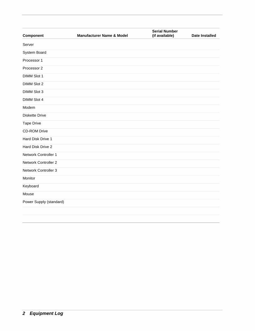
2 Equipment Log
Component Manufacturer Name & ModelSerial Number(if available) Date Installed
Server
System Board
Processor 1
Processor 2
DIMM Slot 1
DIMM Slot 2
DIMM Slot 3
DIMM Slot 4
Modem
Diskette Drive
Tape Drive
CD-ROM Drive
Hard Disk Drive 1
Hard Disk Drive 2
Network Controller 1
Network Controller 2
Network Controller 3
Monitor
Keyboard
Mouse
Power Supply (standard)
Index-1
AAC linkage mode, 1-11Administrative password, 1-12Advance menu
configuring in setup, 3-6
BBattery
installing, 4-6BIOS, 3-3BMC, 1-10Boot menu
configuring in setup, 3-14
CCMOS clear switch, 1-6Configuring system board jumpers summary
description, 3-16Connectors
cooling fan, 1-6floppy disk drive, 1-6IDE, 1-6power supply, 1-6
Controllernetwork, 1-9system board management (BMC), 1-10
Cooling fan connector, 1-6
DDIMM, 1-6
EExit menu
configuring in setup, 3-15
FFloppy disk drive connector, 1-6
IIDE connector, 1-6Installation assumption
Windows 2000, C-3Installing
Windows 2000, C-5Windows NT 4.0, C-8
Integrated peripheral configuration menu,configuring in Setup, 3-7
Intrusion detection, 1-10ISA feature summary, 1-9
JJumpers
CMOS clear, 3-16password, 3-16
LLithium backup battery
installing, 4-6Lithium battery, 1-6
MMain menu
configuring in setup, 3-5Memory
addresses, 1-7Monitoring system status, 1-10
NNetwork
controller, 1-9
OOverview, 1-2
PPassword
administrative, 1-12clearing and changing, 3-18user, 1-12
Password clear switch, 1-6PCi board slot, 1-6Power cords
connecting, 2-7Power supply
monitoring power state, 1-10Power supply connector, 1-6Problems
bootable CD-ROM not detected, 5-12CD-ROM drive activity light, 5-11network, 5-12PCI installation tips, 5-13
Product configuration record table, C-2
RReal-time clock
running SCU to configure settings, 4-6Removing termination board, 4-9, 4-22
Index
Index-2
SSCU
software locking feature, 1-12Security
software lock, SCU, 1-12Security menu
configuring in Setup, 3-11Server management
BMC, 1-10features, 1-10
Setupadvanced menu, 3-6boot menu, 3-14exit menu, 3-15integrated peripheral configuration menu, 3-7main menu, 3-5security menu contents, 3-11
SwitchesCMOS clear, 1-6password clear, 1-6
Systemconfiguring, 3-2powering on, 2-8rear features and controls, 2-5
System Chassis, 1-4System hardware menu
configuring in setup, 3-12
TTermination board
removing, 4-9, 4-22
UUser password, 1-12
WWindows 2000
advanced information, C-4installation assumption, C-3installing operating system software, C-5preparation, C-4required diskettes, C-2
Windows NT 4.0configuring RAID, C-8installing display adapter driver, C-6, C-10installing LAN adapter drivers, C-9installing operating system, C-8required diskettes, C-7

xx

■ ■ ■ ■ ■ ■ ■
■ ■ ■ ■ ■ ■ ■
■ ■ ■ ■ ■ ■ ■
■ ■ ■ ■ ■ ■ ■
■ ■ ■ ■ ■ ■ ■
■ ■ ■ ■ ■ ■ ■
■ ■ ■ ■ ■ ■ ■
■ ■ ■ ■ ■ ■ ■
■ ■ ■ ■ ■ ■ ■
■ ■ ■ ■ ■ ■ ■
■ ■ ■ ■ ■ ■ ■
■ ■ ■ ■ ■ ■ ■
■ ■ ■ ■ ■ ■ ■
456-01586-N00