Embed Size (px)
Citation preview
CAD-USER Rev B
User’s Information ManualModels: 40 - 120
If the information in this manual is not followed exactly, a fire or explosion may result causing property damage, personal injury or loss of life.
This appliance MUST NOT be installed in any location where gasoline or flammable vapors are likely to be present.
WHAT TO DO IF YOU SMELL GAS
• Do not try to light any appliance.• Do not touch any electric switch; do not use any phone in your building.• Immediately call your gas supplier from a near by phone. Follow the gas supplier’s instructions.• If you cannot reach your gas supplier, call the fire department.• Installation and service must be performed by a qualified installer, service agency, or the gas supplier.
� WARNING
Save this manual for future reference.
2
Hazard definitionsThe following defined terms are used throughout this manual to bring attention to the presence of hazards of various risk levels or to important information concerning the life of the product.
� DANGER
� WARNING
� CAUTION
CAUTION
NOTICE
DANGER indicates an imminently hazardous situation which, if not avoided, will result in death or serious injury.
WARNING indicates a potentially hazardous situation which, if not avoided, could result in death or serious injury.
CAUTION indicates a potentially hazardous situation which, if not avoided, may result in minor or moderate injury.
CAUTION used without the safety alert symbol indicates a potentially hazardous situation which, if not avoided, may result in property damage.
NOTICE indicates special instructions on installation, operation, or maintenance that are important but not related to personal injury or property damage.
ContentsHAZARD DEFINITIONS ..................................................... 2PLEASE READ BEFORE PROCEEDING ......................... 31. PREVENT COMBUSTION AIR CONTAMINATION ..... 42. MAINTENANCE SCHEDULE ....................................... 5Maintenance Procedures ................................................... 6 Boiler Must Be Serviced and Maintained .................... 6 Check Boiler Area ......................................................... 6 Check Pressure Temperature Gauge ........................... 6 Check Vent Piping ........................................................ 6 Check Air Piping ........................................................... 6 Check Relief Valve ....................................................... 6 Check Condensate Drain System ............................. 6-7 Check Manual Air Vents ............................................... 8 Test Low Water Cutoff (if installed) .............................. 8 Reset Button (low water cutoff) .................................... 8 Check Boiler Piping (gas and water) ............................ 8 Operate Relief Valve .................................................... 8 Shut Boiler Down .......................................................... 8
3. OPERATING INSTRUCTIONS ..................................... 94. OPERATING INFORMATION Cadet Heating Boiler Control Module ......................... 10 User Programming Sequence .................................... 11 Viewable and Changeable Control Parameters ......... 12 Access Modes ............................................................ 12 Saving Parameters ..................................................... 12 Error Codes - Lockout, Blocking and Notification ....... 13 Revision Notes ................................................. Back Cover
User’s Information Manual
Please read before proceedingThe Cadet Heating Boiler Installation and Service Manual is for use only by a qualified heating installer/service technician. Refer only to this User’s Information Manual for your reference. Improper installation, adjustment, alteration, service or maintenance can cause property damage, personal injury (exposure to hazardous materials) or loss of life. Installation and service must be performed by a qualified installer, service agency or the gas supplier (who must read and follow the supplied instruction before installing, servicing, or removing this boiler. This boiler contains materials that have been identified as carcinogenic, or possibly carcinogenic, to humans).
Failure to adhere to the guidelines on this page can result in severe personal injury, death, or substantial property damage.
Boiler service and maintenance –• To avoid electric shock, disconnect electrical supply before performing maintenance.
• To avoid severe burns, allow boiler to cool before performing maintenance.
Boiler operation –• Do not block flow of combustion or ventilation air to the boiler. This boiler is equipped with a control which will automatically shut down the boiler should air or vent be blocked. If vent or air blockage is easily accessible and removable, remove it. The boiler should attempt to restart. If blockage is not obvious or cannot be removed, have the boiler and system checked by a qualified service technician.
• Should overheating occur or gas supply fail to shut off, do not turn off or disconnect electrical supply to the circulator. Instead, shut off the gas supply at a location external to the appliance.
• Do not use this boiler if any part has been under water. The possible damage to a flooded appliance can be extensive and present numerous safety hazards. Any appliance that has been under water must be replaced.
Boiler water –• Thoroughly flush the system (without boiler connected) to remove sediment. The high-efficiency heat exchanger can be damaged by build-up or corrosion due to sediment.
• Do not use petroleum-based cleaning or sealing compounds in the boiler system. Gaskets and seals in the system may be damaged. This can result in substantial property damage.
• Do not use “homemade cures” or “boiler patent medicines”. Serious damage to the boiler, personnel, and/or property may result.
• Continual fresh make-up water will reduce boiler life. Mineral buildup in the heat exchanger reduces heat transfer, overheats the stainless steel heat exchanger, and causes failure. Addition of oxygen carried in by makeup water can cause internal corrosion. Leaks in boiler or piping must be repaired at once to prevent makeup water.
Freeze protection fluids –• NEVER use automotive antifreeze. Use only inhibited propylene glycol solutions, which are specifically formulated for hydronic systems. Ethylene glycol is toxic and can attack gaskets and seals used in hydronic systems.
When calling or writing about the boiler – Please have the boiler model and serial number from the boiler rating plate.
Consider piping and installation when determining boiler location.
Any claims for damage or shortage in shipment must be filed immediately against the transportation company by the consignee.
Factory warranty (shipped with unit) does not apply to units improperly installed or improperly operated.
3
NOTICE
� WARNING
NOTICE
DO NOT install units in rooms or environments that contain corrosive contaminants (see Table 1A on page 4). Failure to comply could result in severe personal injury, death, or substantial property damage.
� WARNING
User’s Information Manual
1 Prevent combustion air contamination
4
If the boiler combustion air inlet is located in a laundry room or pool facility, for example, these areas will always contain hazardous contaminants.
To prevent the potential of severe personal injury or death, check for areas and products listed in Table 1A before installing the boiler or air inlet piping.
If contaminants are found, you MUST: • Remove contaminants permanently. —OR— • Relocate air inlet and vent terminations to other areas.
� WARNING
� WARNING
Products to avoid:
Spray cans containing chloro/fluorocarbons
Permanent wave solutions
Chlorinated waxes/cleaners
Chlorine-based swimming pool chemicals
Calcium chloride used for thawing
Sodium chloride used for water softening
Refrigerant leaks
Paint or varnish removers
Hydrochloric acid/muriatic acid
Cements and glues
Antistatic fabric softeners used in clothes dryers
Chlorine-type bleaches, detergents, and cleaning solvents found in household laundry rooms
Adhesives used to fasten building products and other similar products
Areas likely to have contaminants
Dry cleaning/laundry areas and establishments
Swimming pools
Metal fabrication plants
Beauty shops
Refrigeration repair shops
Photo processing plants
Auto body shops
Plastic manufacturing plants
Furniture refinishing areas and establishments
New building construction
Remodeling areas
Garages with workshops
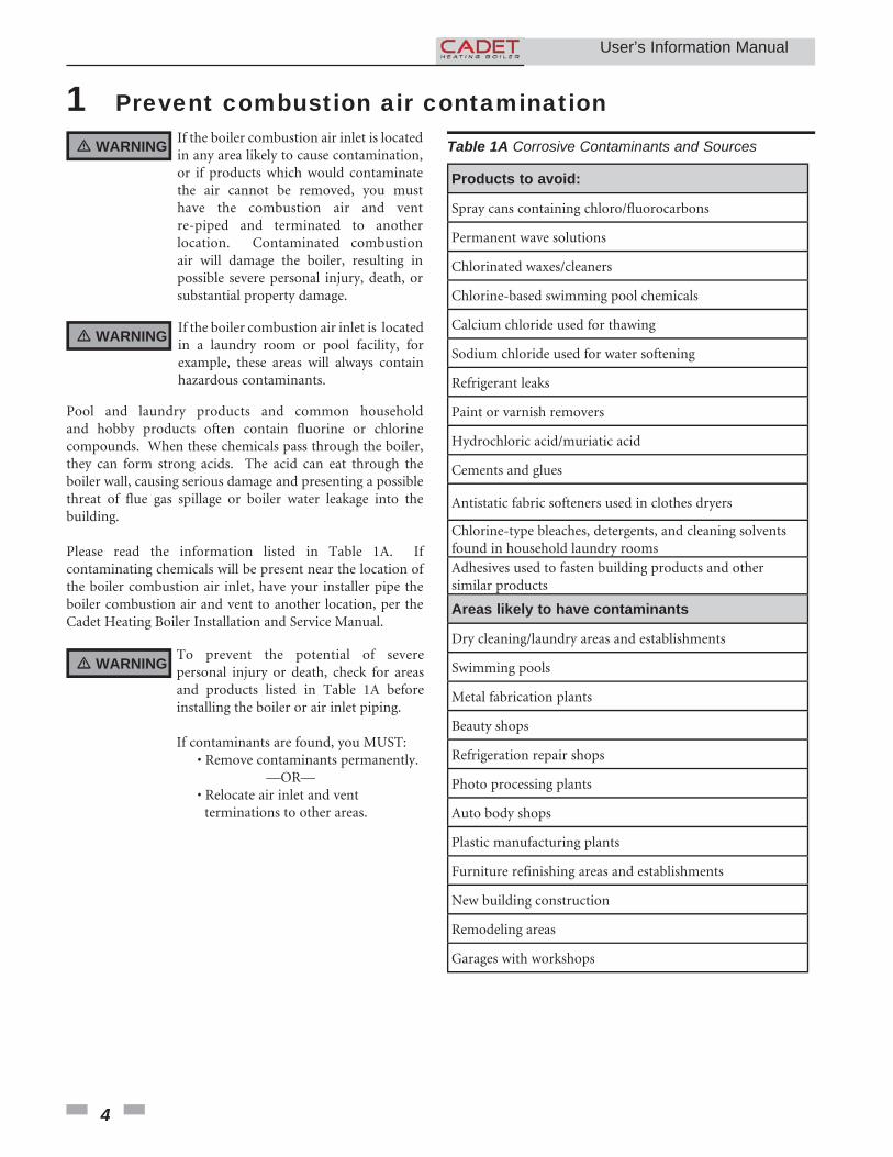
Table 1A Corrosive Contaminants and Sources� WARNING If the boiler combustion air inlet is located in any area likely to cause contamination, or if products which would contaminate the air cannot be removed, you must have the combustion air and vent re-piped and terminated to another location. Contaminated combustion air will damage the boiler, resulting in possible severe personal injury, death, or substantial property damage.
Pool and laundry products and common household and hobby products often contain fluorine or chlorine compounds. When these chemicals pass through the boiler, they can form strong acids. The acid can eat through the boiler wall, causing serious damage and presenting a possible threat of flue gas spillage or boiler water leakage into the building.
Please read the information listed in Table 1A. If contaminating chemicals will be present near the location of the boiler combustion air inlet, have your installer pipe the boiler combustion air and vent to another location, per the Cadet Heating Boiler Installation and Service Manual.
User’s Information Manual
2 Maintenance schedule
5
Service technician(see the Cadet Installation & Service Manual)
General:
• Reported problems
• Inspect interior; clean and vacuum if necessary
• Clean condensate trap
• Check for leaks (water, gas, flue, condensate)
• Verify flue and air lines in good condition and sealed tight
• Check system water pressure/system piping/expansion tank
• Check control settings
• Check ignition and flame sense electrodes (sand off any deposits; clean and reposition)
• Wiring and connections
• Perform start-up checkout and performance verification per Section 10 in the Cadet Heating Boiler Installation and Service Manual.
• Flame inspection (stable, uniform)
• Flame signal (at least 10 microamps at high fire)
• Clean the heat exchanger if flue temperature is more than 54°F above return water temperature.
If combustion or performance indicate need:
• Clean heat exchanger • Remove the door and burner assembly.
Owner maintenance(see pages 6 - 8 for detailed instructions)
Daily • Check boiler area
• Check pressure/temperature gauge
Monthly
• Check vent piping
• Check air piping
• Check air and vent termination screens
• Check relief valve
• Check condensate drain system
• Check air vents
Periodically • Test low water cutoff (if used)
• Reset button (low water cutoff)
Every6 months
• Check boiler piping (gas and water) for leaks
• Operate relief valve
Endof season months
• Shut boiler down (unless boiler used for domestic hot water)
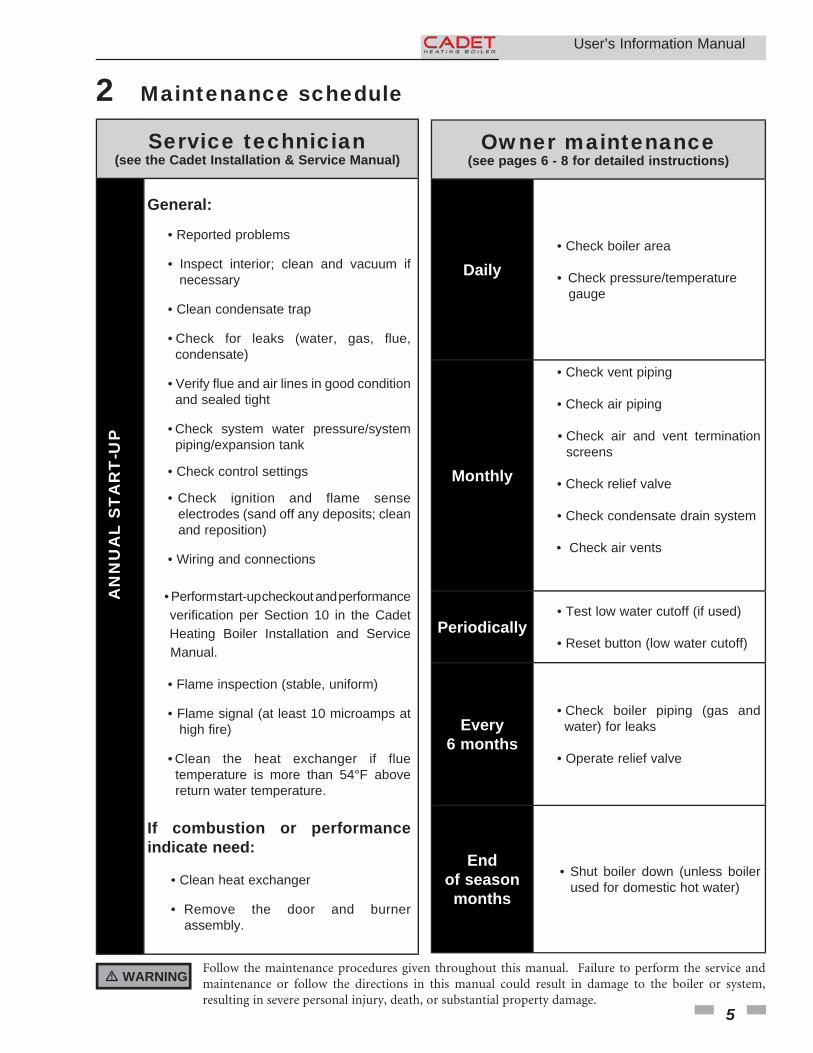
� WARNING Follow the maintenance procedures given throughout this manual. Failure to perform the service and maintenance or follow the directions in this manual could result in damage to the boiler or system, resulting in severe personal injury, death, or substantial property damage.
AN
NU
AL
ST
AR
T-U
P
2 Maintenance schedule
6
Maintenance procedures
Boiler must be serviced and maintained
� WARNING The boiler must be inspected and started annually at the beginning of the heating season by a qualified service technician. In addition, the maintenance and care of the boiler designated on page 5 of this manual and explained on pages 6 through 8 must be performed to assure maximum boiler efficiency and reliability. Failure to service and maintain the boiler and system could result in equipment failure, causing possible severe personal injury, death, or substantial property damage.
NOTICE The following information provides detailed instructions for completing the maintenance items listed in the maintenance schedule on page 5. In addition to this maintenance, the boiler must be serviced and started up at the beginning of each heating season by a qualified service technician.
Check boiler area
� WARNING To prevent potential of severe personal injury, death, or substantial property damage, eliminate all materials discussed below from the boiler vicinity and the vicinity of the boiler combustion air inlet. If contaminants are found:
Remove products immediately from the area. If they have been there for an extended period, call a qualified service technician to inspect the boiler for possible damage from acid corrosion.
If products cannot be removed, immediately call a qualified service technician to re-pipe vent and air piping and locate vent termination/air intake away from contaminated areas.
1. Combustible/flammable materials -- Do not store combustible materials, gasoline or any other flammable vapors or liquids near the boiler. Remove immediately if found.
2. Air contaminants -- Products containing chlorine or fluorine, if allowed to contaminate the boiler intake air, will cause acidic condensate in the boiler. This will cause significant damage to the boiler if allowed to continue.
Read the list of potential materials listed in Table 1A on page 4 of this manual. If any of these products are in the room from which the boiler takes its combustion air, they must be removed immediately or the boiler combustion air (and vent termination) must be relocated to another area.
Check pressure/temperature gauge
1. Make sure the pressure reading on the boiler pressure/ temperature gauge does not exceed 24 psi. Higher pressure may indicate a problem with the expansion tank.
2. Contact a qualified service technician if problem persists.
Check vent piping
1. Visually inspect the flue gas vent piping for any signs of blockage, leakage, or deterioration of the piping. Notify your qualified service technician at once if you find any problems.
� WARNING Failure to inspect the vent system as noted above and have it repaired by a qualified service technician can result in vent system failure, causing severe personal injury or death.
Check air piping1. Visually inspect the air inlet termination to be sure it is unobstructed. Inspect the entire length of air piping to ensure piping is intact and all joints are properly sealed.
2. Call your qualified service technician if you notice any problems.
Check relief valve1. Inspect the boiler relief valve and the relief valve discharge pipe for signs of weeping or leakage.
2. If the relief valve often weeps, the expansion tank may not be working properly. Immediately contact your qualified service technician to inspect the boiler and system.
Check condensate drain systemInspect/check condensate lines and fittings
Inspect the condensate drain line, condensate PVC fittings and condensate trap.
User’s Information Manual
2 Maintenance schedule (continued)
7
Clean/Inspect Trap Assembly
Remove the clean out cap on the bottom of the trap. Let the condensate and any debris drain out.
� WARNING
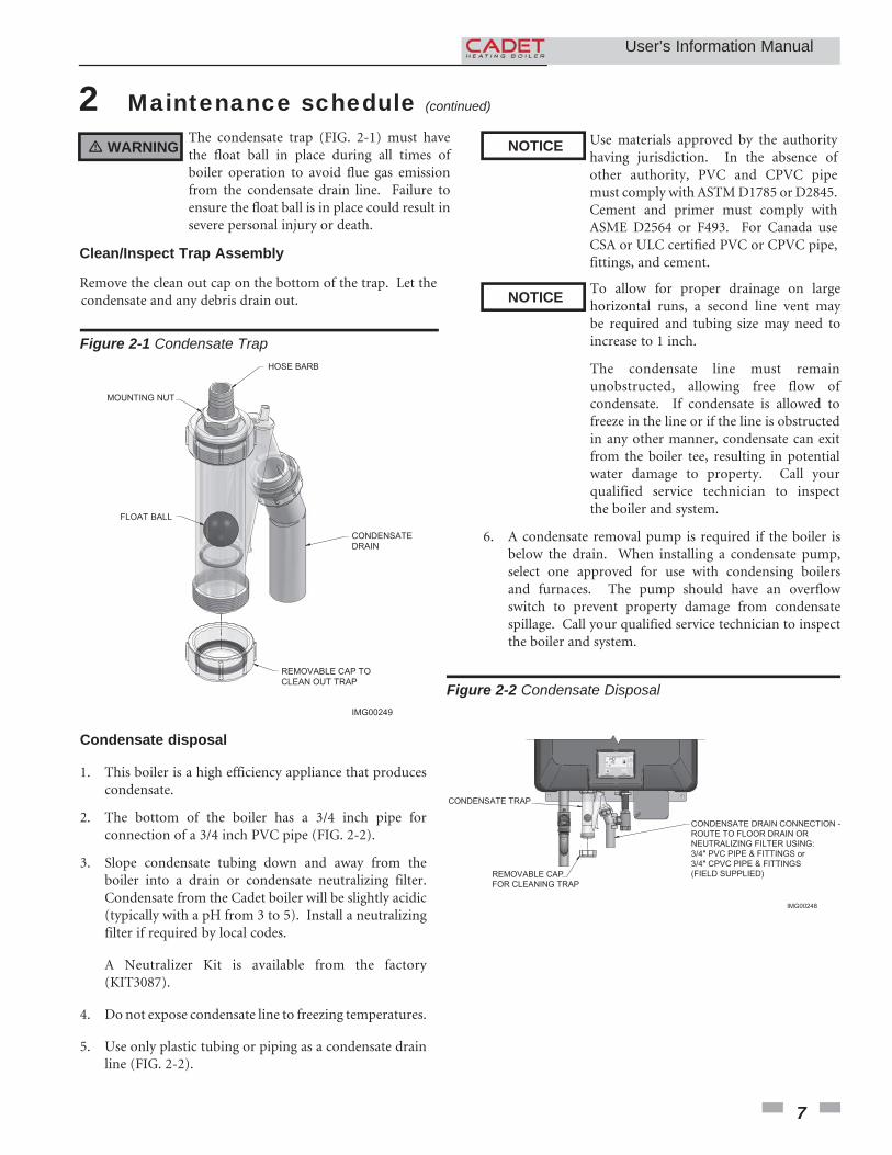
Figure 2-1 Condensate Trap
Condensate disposal
1. This boiler is a high efficiency appliance that produces condensate.
2. The bottom of the boiler has a 3/4 inch pipe for connection of a 3/4 inch PVC pipe (FIG. 2-2).
3. Slope condensate tubing down and away from the boiler into a drain or condensate neutralizing filter. Condensate from the Cadet boiler will be slightly acidic (typically with a pH from 3 to 5). Install a neutralizing filter if required by local codes.
A Neutralizer Kit is available from the factory (KIT3087).
4. Do not expose condensate line to freezing temperatures.
5. Use only plastic tubing or piping as a condensate drain line (FIG. 2-2).
Use materials approved by the authority having jurisdiction. In the absence of other authority, PVC and CPVC pipe must comply with ASTM D1785 or D2845. Cement and primer must comply with ASME D2564 or F493. For Canada use CSA or ULC certified PVC or CPVC pipe, fittings, and cement.
6. A condensate removal pump is required if the boiler is below the drain. When installing a condensate pump, select one approved for use with condensing boilers and furnaces. The pump should have an overflow switch to prevent property damage from condensate spillage. Call your qualified service technician to inspect the boiler and system.
NOTICE
NOTICE To allow for proper drainage on large horizontal runs, a second line vent may be required and tubing size may need to increase to 1 inch.
The condensate line must remain unobstructed, allowing free flow of condensate. If condensate is allowed to freeze in the line or if the line is obstructed in any other manner, condensate can exit from the boiler tee, resulting in potential water damage to property. Call your qualified service technician to inspect the boiler and system.
Figure 2-2 Condensate Disposal
The condensate trap (FIG. 2-1) must have the float ball in place during all times of boiler operation to avoid flue gas emission from the condensate drain line. Failure to ensure the float ball is in place could result in severe personal injury or death.
CONDENSATE
DRAIN
REMOVABLE CAP TO
CLEAN OUT TRAP
HOSE BARB
FLOAT BALL
IMG00249
MOUNTING NUT
CONDENSATE TRAP
REMOVABLE CAP
FOR CLEANING TRAP
CONDENSATE DRAIN CONNECTION -
ROUTE TO FLOOR DRAIN OR
NEUTRALIZING FILTER USING:
3/4" PVC PIPE & FITTINGS or
3/4" CPVC PIPE & FITTINGS
(FIELD SUPPLIED)
IMG00248
User’s Information Manual
2 Maintenance schedule
8
� WARNING Have leaks fixed at once by a qualified service technician. Failure to comply could result in severe personal injury, death, or substantial property damage.
2. Read the boiler pressure/temperature gauge to make sure the system is pressurized. Lift the relief valve top lever slightly, allowing water to relieve through the valve and discharge piping.
3. If water flows freely, release the lever and allow the valve to seat. Watch the end of the relief valve discharge pipe to ensure that the valve does not weep after the line has had time to drain. If the valve weeps, lift the seat again to attempt to clean the valve seat. If the valve continues to weep afterwards, contact your qualified service technician to inspect the valve and system.
4. If water does not flow from the valve when you lift the lever completely, the valve or discharge line may be blocked. Immediately shut down the boiler, following the operating instructions on page 9 of this manual. Call your qualified service technician to inspect the boiler and system.
Shut boiler down (unless boiler is used for Domestic Water)
1. Follow “To Turn Off Gas to Appliance” on page 9 of this manual.
2. Do not drain the system unless exposure to freezing temperatures will occur.
3. Do not drain the system if it is filled with an antifreeze solution.
4. DO NOT shut down boilers used for domestic water heating, they must operate year-round.
3. Replace the front access door.
Test low water cutoff (if installed)
1. If the system is equipped with a low water cutoff, test the low water cutoff periodically during the heating season, following the low water cutoff manufacturer’s instructions.
Reset button (low water cutoff)
1. Testing the low water cutoff shuts the unit off. Press the RESET button on the low water cutoff to turn the unit back on.
Check boiler piping (gas and water)
1. Remove the boiler front access door and perform a gas leak inspection per steps 1 through 7 of the Operating Instructions on page 9. If gas odor or leak is detected, immediately shut down the boiler following the procedures on page 9. Call a qualified service technician.
2. Visually inspect for leaks around water piping. Also inspect the circulators, relief valve, and fittings. Immediately call a qualified service technician to repair any leaks.
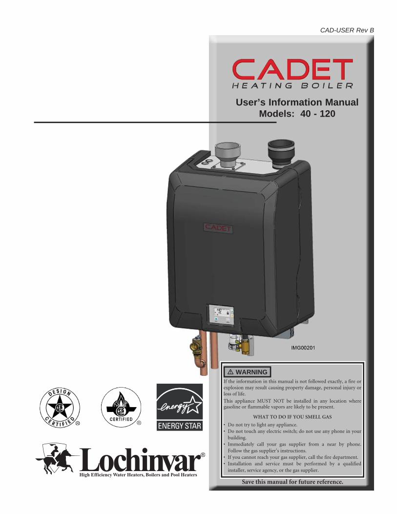
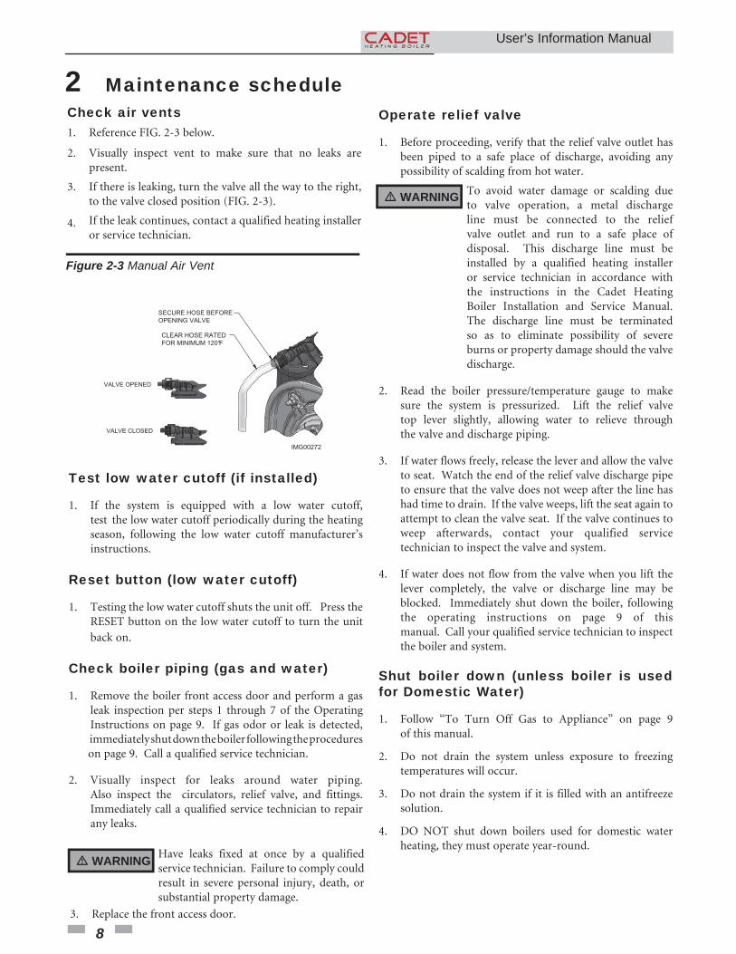
Check air vents1. Reference FIG. 2-3 below.
2. Visually inspect vent to make sure that no leaks are
present.
3. If there is leaking, turn the valve all the way to the right, to the valve closed position (FIG. 2-3).
4. If the leak continues, contact a qualified heating installer or service technician.
Figure 2-3 Manual Air Vent
Operate relief valve
1. Before proceeding, verify that the relief valve outlet has been piped to a safe place of discharge, avoiding any possibility of scalding from hot water.
� WARNING To avoid water damage or scalding due to valve operation, a metal discharge line must be connected to the relief valve outlet and run to a safe place of disposal. This discharge line must be installed by a qualified heating installer or service technician in accordance with the instructions in the Cadet Heating Boiler Installation and Service Manual. The discharge line must be terminated so as to eliminate possibility of severe burns or property damage should the valve discharge.
IMG00272
VALVE CLOSED
VALVE OPENED
CLEAR HOSE RATED
FOR MINIMUM 120°F
SECURE HOSE BEFORE
OPENING VALVE
User’s Information Manual
9
3 Operating instructions
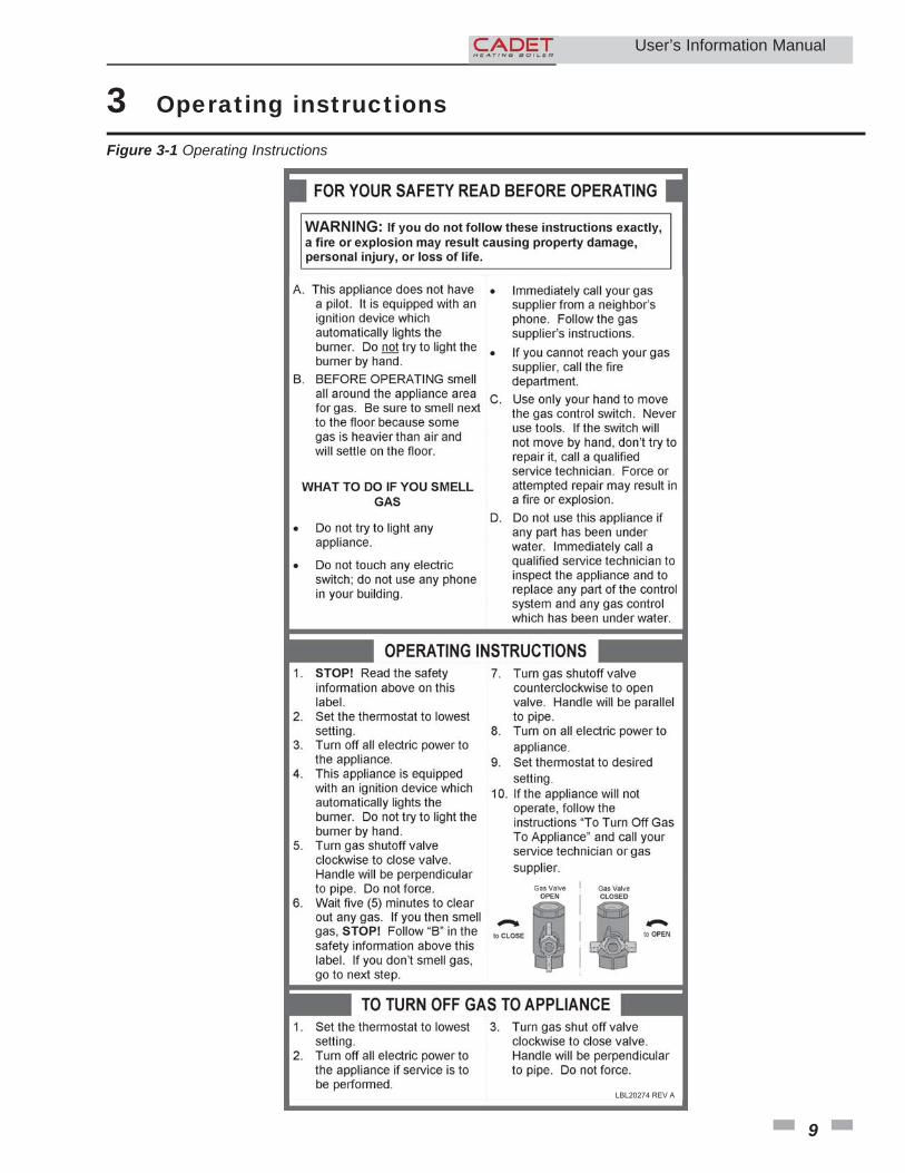
Figure 3-1 Operating Instructions
User’s Information Manual
LBL20274 REV A
10
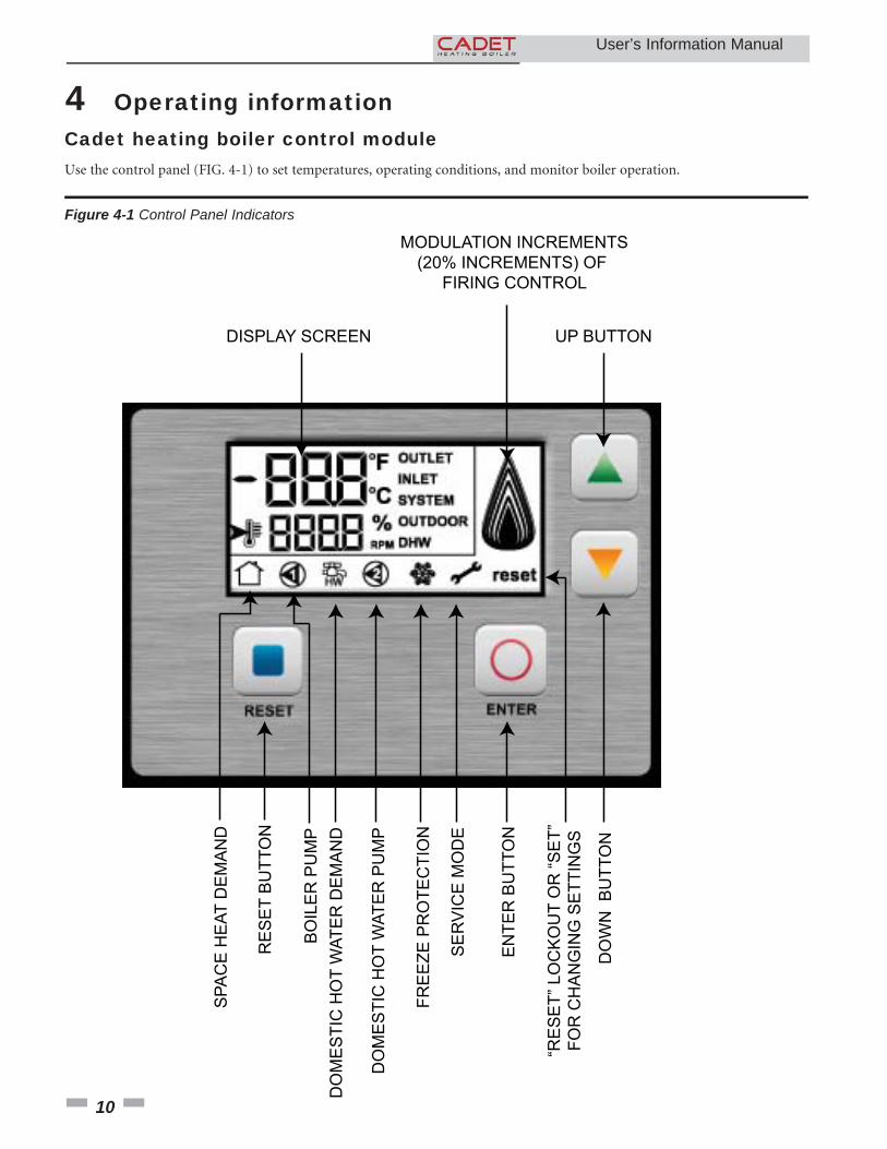
4 Operating informationCadet heating boiler control module
MODULATION INCREMENTS
(20% INCREMENTS) OF
FIRING CONTROL
DO
WN
B
UT
TO
N
“RE
SE
T”
LO
CK
OU
T O
R “
SE
T”
FO
R C
HA
NG
ING
SE
TT
ING
S
EN
TE
R B
UT
TO
N
RE
SE
T B
UT
TO
N
SE
RV
ICE
MO
DE
FR
EE
ZE
PR
OT
EC
TIO
N
DO
ME
ST
IC H
OT
WA
TE
R P
UM
P
DO
ME
ST
IC H
OT
WA
TE
R D
EM
AN
D
SP
AC
E H
EA
T D
EM
AN
D
BO
ILE
R P
UM
P
DISPLAY SCREEN UP BUTTON
Figure 4-1 Control Panel Indicators
Use the control panel (FIG. 4-1) to set temperatures, operating conditions, and monitor boiler operation.
User’s Information Manual
User’s Information Manual
4 Operating information (continued)
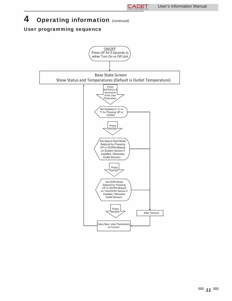
User programming sequence
A�er Timeout
Base State ScreenShow Status and Temperatures (Default is Outlet Temperature)
ON/OFF
Press UP for 5 seconds to
either Turn On or Off Unit
Press
ENTER for 5
seconds to
Enter User
Parameters
Set Degrees in °C or
°F by Pressing UP or
DOWN
Set Space Heat Mode
Setpoint by Pressing
UP or DOWN (Based
on System Sensor if
Installed, Otherwise
Outlet Sensor)
Press
ENTER
Save New User Parameters
to Control
Press
ENTER
After Timeout
Set DHW Mode
Setpoint by Pressing
UP or DOWN (Based
on Tank/DHW Sensor if
Installed, Otherwise
Outlet Sensor)
Press
ENTER
11
12
Viewable and changeable control parameters
Temperature Units (°C/°F)
The control can be configured to display temperature in either °C or °F. This parameter can be changed by accessing parameter u01.
Set SH Temperature
The Space Heat Demand Temperature can be adjusted UP or DOWN by accessing parameter u02. Temperature range is 32°F to parameter P90.
Set tank DHW Tank Setpoint (if tank sensor present)
The DHW Setpoint Temperature can be adjusted UP or DOWN by accessing parameter u03. Temperature range is 60°F to 185°F.
Set SH Setpoint at Minimum Outdoor Temperature
When the outdoor air temperature drops to 25°F, the calculated set point will be at this setting (reference Table 4-3 in the Cadet Heating Boiler Installation and Service Manual). If the outdoor air temperature drops further, the set point will continue to increase above this setting. However, if SH set point is set lower than the calculated set point, the water temperature will be limited by the SH set point instead. This parameter can be changed by the installer by accessing the P01. Temperature range is 68°F to 250°F.
CAUTION Before changing parameters, note the settings so that the unit can be returned to its original operating parameters.
4 Operating information
Access modesUser
Press the ENTER button for 5 seconds.
Installer
Most parameters are available only to the installer, accessible by entering the installer key combination: Press the ENTER and DOWN buttons simultaneously for 5 seconds.
Saving parameters (reference the Parameter Table in the Cadet Heating Boiler Installation and Service Manual)
To save parameters and exit programming:
Press the ENTER button to go to the end of the Parameter List, then press ENTER again. Otherwise, the parameters will be saved automatically after Timeout.
To enter a parameter and continue programming:
Press the UP or DOWN button to change parameters. Press ENTER to move to the next parameter and to the end of the Parameter List. Press ENTER to save and return to the Base Screen. Otherwise, the parameters will be saved automatically after Timeout.
User’s Information Manual
13
User’s Information Manual
4 Operating information (continued)
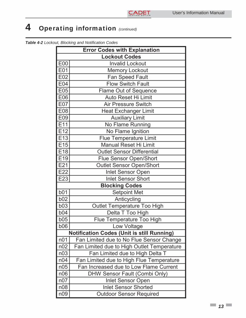
E00 Invalid Lockout
E01 Memory Lockout
E02 Fan Speed Fault
E04 Flow Switch Fault
E05 Flame Out of Sequence
E06 Auto Reset Hi Limit
E07 Air Pressure Switch
E08 Heat Exchanger Limit
E09 Auxiliary Limit
E11 No Flame Running
E12 No Flame Ignition
E13 Flue Temperature Limit
E15 Manual Reset Hi Limit
E18 Outlet Sensor Differential
E19 Flue Sensor Open/Short
E21 Outlet Sensor Open/Short
E22 Inlet Sensor Open
E23 Inlet Sensor Short
b01 Setpoint Met
b02 Anticycling
b03 Outlet Temperature Too High
b04 Delta T Too High
b05 Flue Temperature Too High
b06 Low Voltage
n01 Fan Limited due to No Flue Sensor Change
n02 Fan Limited due to High Outlet Temperature
n03 Fan Limited due to High Delta T
n04 Fan Limited due to High Flue Temperature
n05 Fan Increased due to Low Flame Current
n06 DHW Sensor Fault (Combi Only)
n07 Inlet Sensor Open
n08 Inlet Sensor Shorted
n09 Outdoor Sensor Required
Error Codes with ExplanationLockout Codes
Blocking Codes
Notification Codes (Unit is still Running)
Table 4-2 Lockout, Blocking and Notification Codes
14
NOTES User’s Information Manual
15
NOTES User’s Information Manual

Revision Notes: Revision A (ECO C10659) initial release.
Revision B (ECO C14411) reflects the addition of the corrosive contaminant warning on page 3 (R06313).
CAD-USER Rev B1/14