Embed Size (px)
Citation preview
深圳市盈科互动科技有限公司
CWT5
China Wintop Tech Shenzhen Co., Ltd.
Exchange: +86-755-26719943 Fax: +86-755-26719940
Sales hotline: +86-755-86368161, 86368160
Email: [email protected]
Website: http://www.mobq2000.com
Address: Room 315, Unit C, Research Institude of Tsinghua University, South Science and
Technology Park, Nanshan District, Shenzhen City Zip code: 518057
User’s Manual of CWT5010 Products Version 2.0 (2008-5-13)
The ownership of this Manual exclusively belongs to China Wintop Tech Shenzhen
Co., Ltd.. Reproduction, distribution and reprint of any part of this Manual by any
organization or individual are not allowed without the written approval of our
Company; otherwise, all consequences caused shall be responded by the offender.
Note: This Manual is made only for CWT5000 software configuration. Our Company
reserves the right to make final interpretation and all rights to improve the product
described therein.
Tel: +86-755-26719943 | Fax: +86-755-26719940 | Web site: http://www.mobq2000.com
CWT5010 User’s Manual China Wintop Tech Shenzhen Co., Ltd .
22
Table of Contents
I Preface........................................................................................................................3
Copyright statement ........................................................................................................................3
II General specification for the application of GSM technology on remote communication and human computer interaction (M2H) ...................................................................4
Comparison among several radio communication technologies....................................................4
III Brief introduction of CWT5000 GSM DTU/RTU.........................................................5
Main features of product .................................................................................................................5
Main technical parameter................................................................................................................6
CWT5010 interface introduction .....................................................................................................7
Supplies list of CWT5010................................................................................................................8
IV Configuration guide of CWT5000 product series ....................................................11
4.1.1 Preparation for operation and being under configuration mode..........................................11
4.1.2 Basic parameter configuration ..........................................................................................13
4.1.3 Switching value input alarm ..............................................................................................15
4.1.3 Relay drive output control .................................................................................................17
4.1.4 Linkage configuration among switching value inputs etc. and relay drive output ...............19
4.1.5 AD sample alarm (function of CWT5011) .........................................................................20
4.1.6 Internal temperature sensor (optional function) ................................................................23
4.1.7 Power-off alarm (optional function)......................................................................................24
4.1.8 Buzzer alarm (function of CWT5011)................................................................................24
4.1.9 Relevant parameter configuration for alarm modes ............................................................24
V Data transmission ....................................................................................................25
VI Other common commands of serial port .................................................................26
VII User-defined short-message configuration ............................................................26
Tel: +86-755-26719943 | Fax: +86-755-26719940 | Web site: http://www.mobq2000.com
CWT5010 User’s Manual China Wintop Tech Shenzhen Co., Ltd .
33
I Preface
Thank you for using the Short-message alarming controller of CWT5000 GSM network from China
Wintop Tech Shenzhen Co., Ltd. You will know well about the functions and operation methods of this
product quickly through this Product Specification.
This product is mainly used for remote alarming and control application based on GSM network. Please
use it according to the parameters and technical specifications in the Specification. Meanwhile, the
Notes shall be considered for the usage of radio-control products, especially GSM products. Our
Company bears no liability for property loss or bodily injury arising from abnormal or incorrect usage of
this product.
This Specification applies to CWT5000 and CWT5010 product users.
Exemption statement: Where the equipment fails to work due to network upgrade by the operator, our
Company offers no free upgrade service. In the event that the network service of the operator is
suspended due to special reasons and CWT5000 equipment cannot function correctly thereby, our
Company bears no liability for the consequences thereout.
Copyright statement
The ownership of this Manual exclusively belongs to China Wintop Tech Shenzhen Co., Ltd..
Reproduction, distribution and reprint of any part of this Manual by any organization or individual are not
allowed without the written approval of our Company; otherwise, all consequences caused shall be
responded by the offender
Tel: +86-755-26719943 | Fax: +86-755-26719940 | Web site: http://www.mobq2000.com
CWT5010 User’s Manual China Wintop Tech Shenzhen Co., Ltd .
44
II General specification for the application of GSM technology on remote communication and human computer interaction (M2H)
Along with the improvement of the public radio communication network of GSM/GPRS network, more
and more applications based on GSM/GPRS network popularize in different industries. The coverage
percentage of GSM/GPRS network in China now has reached over 95%, providing services of voice,
short-message and GPRS network services. The short-message service of GSM network and packet
radio data transmission service of GPRS network establish a favorable network application foundation
for remote data transmission and human computer interaction. GSM/GPRS technologies have become
a burgeoning radio remote communication channel for application in different industries.
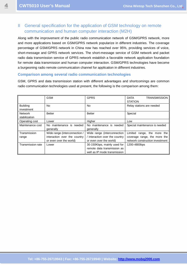
Comparison among several radio communication techno logies
GSM, GPRS and data transmission station with different advantages and shortcomings are common
radio communication technologies used at present, the following is the comparison among them:
GSM GPRS DATA TRANSMISSION STATION
Building investment
No No Relay stations are needed
Network stabilization
Better Better Special
Operating cost Lower Higher Low Maintenance cost No maintenance is needed
generally No maintenance is needed generally
Special maintenance is needed
Transmission range
Wide range (interconnection / interaction over the country or even over the world)
Wide range (interconnection / interaction over the country or even over the world)
Limited range, the more the coverage range, the more the network construction investment
Transmission rate Lower 30-150Kbps, mainly used for remote data transmission as well as IP mode transmission
1200-4800bps
Tel: +86-755-26719943 | Fax: +86-755-26719940 | Web site: http://www.mobq2000.com
CWT5010 User’s Manual China Wintop Tech Shenzhen Co., Ltd .
55
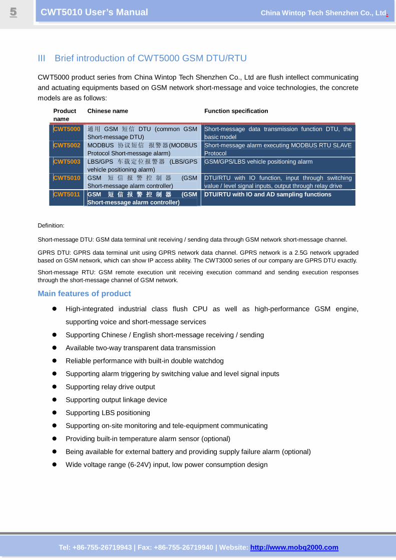
III Brief introduction of CWT5000 GSM DTU/RTU CWT5000 product series from China Wintop Tech Shenzhen Co., Ltd are flush intellect communicating
and actuating equipments based on GSM network short-message and voice technologies, the concrete
models are as follows:
Product name
Chinese name Function specification
CWT5000 通用 GSM 短信 DTU (common GSM Short-message DTU)
Short-message data transmission function DTU, the basic model
CWT5002 MODBUS 协议短信 报警器 (MODBUS Protocol Short-message alarm)
Short-message alarm executing MODBUS RTU SLAVE Protocol
CWT5003 LBS/GPS 车载定位报警器 (LBS/GPS vehicle positioning alarm)
GSM/GPS/LBS vehicle positioning alarm
CWT5010 GSM 短 信 报 警 控 制 器 (GSM Short-message alarm controller)
DTU/RTU with IO function, input through switching value / level signal inputs, output through relay drive
CWT5011 GSM 短 信 报 警 控 制 器短 信 报 警 控 制 器短 信 报 警 控 制 器短 信 报 警 控 制 器 (GSM Short-message alarm controller)
DTU/RTU with IO and AD sampling functions
Definition:
Short-message DTU: GSM data terminal unit receiving / sending data through GSM network short-message channel.
GPRS DTU: GPRS data terminal unit using GPRS network data channel. GPRS network is a 2.5G network upgraded based on GSM network, which can show IP access ability. The CWT3000 series of our company are GPRS DTU exactly.
Short-message RTU: GSM remote execution unit receiving execution command and sending execution responses through the short-message channel of GSM network.
Main features of product
High-integrated industrial class flush CPU as well as high-performance GSM engine,
supporting voice and short-message services
Supporting Chinese / English short-message receiving / sending
Available two-way transparent data transmission
Reliable performance with built-in double watchdog
Supporting alarm triggering by switching value and level signal inputs
Supporting relay drive output
Supporting output linkage device
Supporting LBS positioning
Supporting on-site monitoring and tele-equipment communicating
Providing built-in temperature alarm sensor (optional)
Being available for external battery and providing supply failure alarm (optional)
Wide voltage range (6-24V) input, low power consumption design
Tel: +86-755-26719943 | Fax: +86-755-26719940 | Web site: http://www.mobq2000.com
CWT5010 User’s Manual China Wintop Tech Shenzhen Co., Ltd .
66
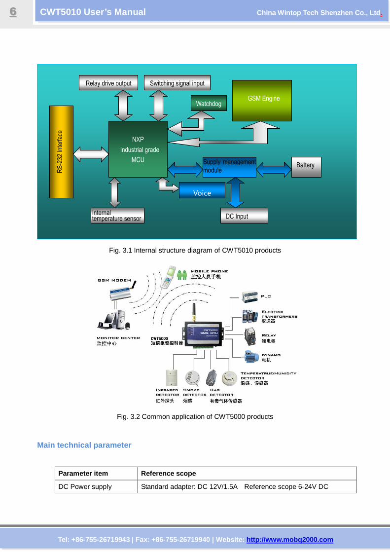
Fig. 3.1 Internal structure diagram of CWT5010 products
Fig. 3.2 Common application of CWT5000 products
Main technical parameter
Parameter item Reference scope
DC Power supply Standard adapter: DC 12V/1.5A Reference scope 6-24V DC
NXP
Industrial grade
MCU
GSM Engine
Switching signal input Relay drive output
RS-232 Interface
Supply management
module Battery
DC Input Internal temperature sensor
Watchdog
Voice
Tel: +86-755-26719943 | Fax: +86-755-26719940 | Web site: http://www.mobq2000.com
CWT5010 User’s Manual China Wintop Tech Shenzhen Co., Ltd .
77
Power consumption 12V input Max. 50mA/Average 50mA
Frequency range Dual-frequency 900/1800, compatible with GSM Phase 2/2+
SIM Card Supporting 3V SIM Card
Antenna 50 Ω SMA Antenna interface
Serial RS-232C, Default communication parameter 9600,n,8,0,1
Temperature range -10-+70 °C
Humidity range Relative humidity 95% (condensation free)
Output drive voltage Equal to input DC voltage
Output drive power Drive voltage ≤35V, drive current ≤200mA
On state input current Max. 0.33mA
Input signal Dry contact or 0V-3.3V level signal
Exterior dimension 95×63×25mm
Weight 130 g
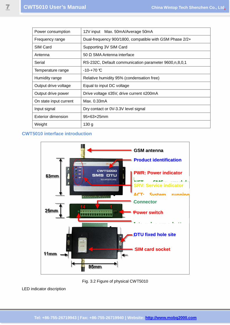
CWT5010 interface introduction
Fig. 3.2 Figure of physical CWT5010
LED indicator discription
GGSSMM aanntteennnnaa
PPrroodduucctt iiddeenntt ii ff iiccaatt iioonn
DDTTUU ff iixxeedd hhoollee ssiittee
PPWWRR:: PPoowweerr iinnddiiccaattoorr
PPoowweerr sswwii ttcchh
SSIIMM ccaarrdd ssoocckkeett
NNEETT:: SSMMSS mmoodduullee
IInntteerrnnaall bbaatttteerryy
CCoonnnneeccttoorr
SSRRVV:: SSeerrvviiccee iinnddiiccaattoorr
AACCTT:: SSyysstteemm rruunnnniinngg
Tel: +86-755-26719943 | Fax: +86-755-26719940 | Web site: http://www.mobq2000.com
CWT5010 User’s Manual China Wintop Tech Shenzhen Co., Ltd .
88
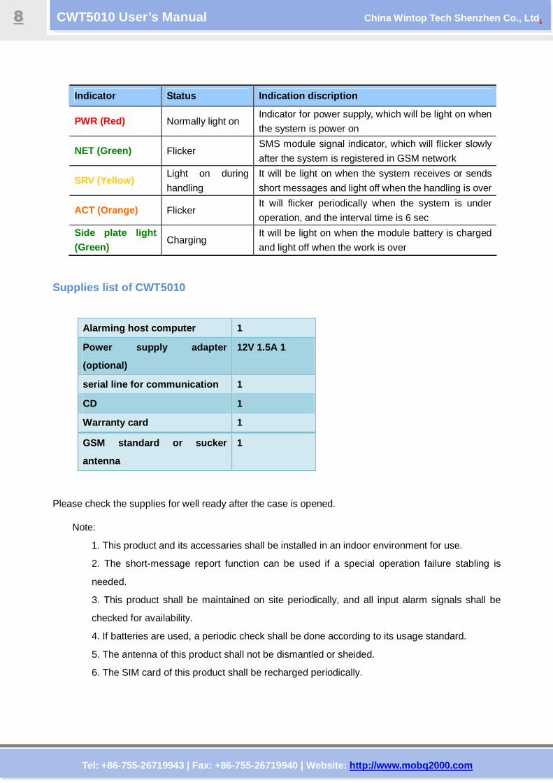
Indicator Status Indication discription
PWR (Red) Normally light on Indicator for power supply, which will be light on when
the system is power on
NET (Green) Flicker SMS module signal indicator, which will flicker slowly
after the system is registered in GSM network
SRV (Yellow) Light on during
handling
It will be light on when the system receives or sends
short messages and light off when the handling is over
ACT (Orange) Flicker It will flicker periodically when the system is under
operation, and the interval time is 6 sec
Side plate light (Green)
Charging It will be light on when the module battery is charged
and light off when the work is over
Supplies list of CWT5010
Alarming host computer 1
Power supply adapter
(optional)
12V 1.5A 1
serial line for communication 1
CD 1
Warranty card 1
GSM standard or sucker
antenna
1
Please check the supplies for well ready after the case is opened.
Note:
1. This product and its accessaries shall be installed in an indoor environment for use.
2. The short-message report function can be used if a special operation failure stabling is
needed.
3. This product shall be maintained on site periodically, and all input alarm signals shall be
checked for availability.
4. If batteries are used, a periodic check shall be done according to its usage standard.
5. The antenna of this product shall not be dismantled or sheided.
6. The SIM card of this product shall be recharged periodically.
Tel: +86-755-26719943 | Fax: +86-755-26719940 | Web site: http://www.mobq2000.com
CWT5010 User’s Manual China Wintop Tech Shenzhen Co., Ltd .
99
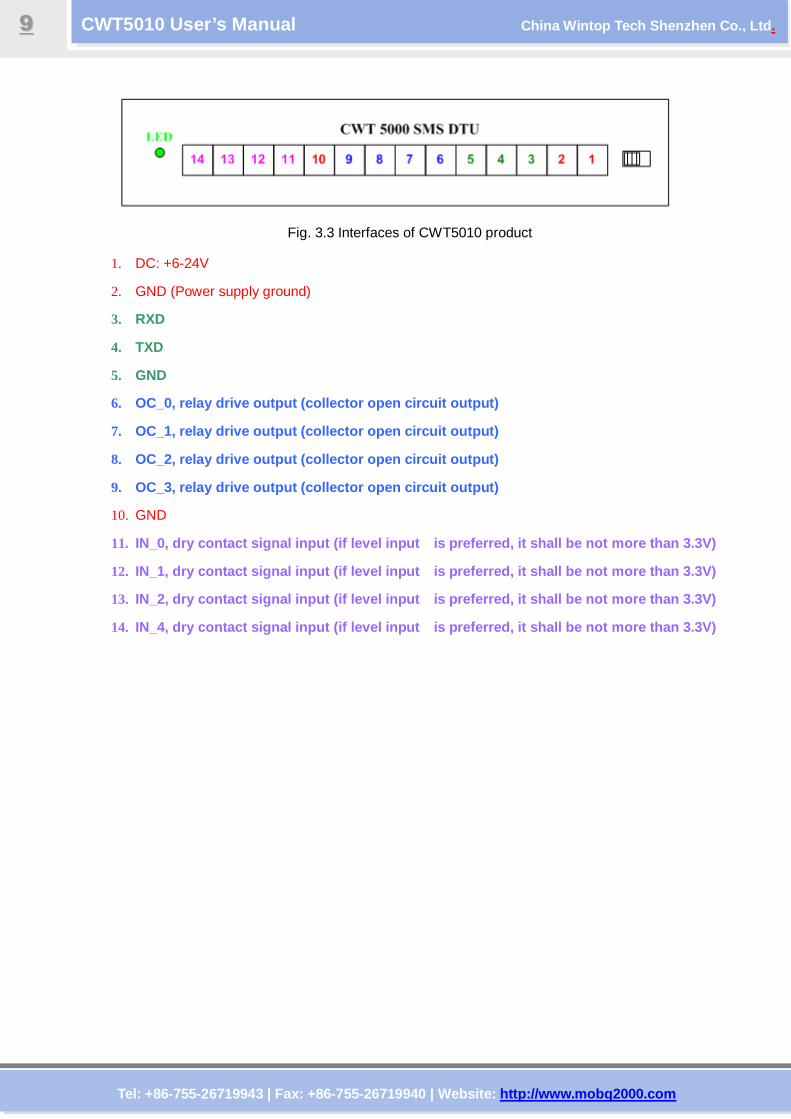
Fig. 3.3 Interfaces of CWT5010 product
1. DC: +6-24V
2. GND (Power supply ground)
3. RXD
4. TXD
5. GND
6. OC_0, relay drive output (collector open circuit o utput)
7. OC_1, relay drive output (collector open circuit o utput)
8. OC_2, relay drive output (collector open circuit o utput)
9. OC_3, relay drive output (collector open circuit o utput)
10. GND
11. IN_0, dry contact signal input (if level input is preferred, it shall be not more than 3.3V)
12. IN_1, dry contact signal input (if level input is preferred, it shall be not more than 3.3V)
13. IN_2, dry contact signal input (if level input is preferred, it shall be not more than 3.3V)
14. IN_4, dry contact signal input (if level input is preferred, it shall be not more than 3.3V)
Tel: +86-755-26719943 | Fax: +86-755-26719940 | Web site: http://www.mobq2000.com
CWT5010 User’s Manual China Wintop Tech Shenzhen Co., Ltd .
1100
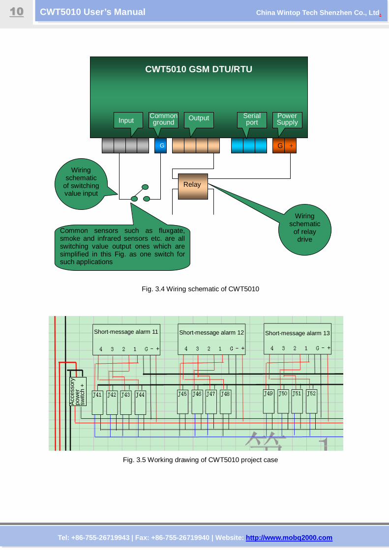
Fig. 3.4 Wiring schematic of CWT5010
Fig. 3.5 Working drawing of CWT5010 project case
CWT5010 GSM DTU/RTU
G G +
Power Supply
Serial port
Output Input Common ground
Wiring schematic
of switching value input
Relay
Wiring schematic
of relay drive
Common sensors such as fluxgate, smoke and infrared sensors etc. are all switching value output ones which are simplified in this Fig. as one switch for such applications
Short-message alarm 11 Short-message alarm 12 Short-message alarm 13
Acc
esso
ry
pow
er
switc
h +
Tel: +86-755-26719943 | Fax: +86-755-26719940 | Web site: http://www.mobq2000.com
CWT5010 User’s Manual China Wintop Tech Shenzhen Co., Ltd .
1111
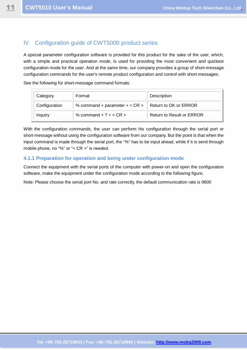
IV Configuration guide of CWT5000 product series
A special parameter configuration software is provided for this product for the sake of the user, which,
with a simple and practical operation mode, is used for providing the most convenient and quickest
configuration mode for the user. And at the same time, our company provides a group of short-message
configuration commands for the user's remote product configuration and control with short-messages.
See the following for short-message command formats:
Category Format Description
Configuration % command + parameter + < CR > Return to OK or ERROR
Inquiry % command + ? + < CR > Return to Result or ERROR
With the configuration commands, the user can perform his configuration through the serial port or
short-message without using the configuration software from our company. But the point is that when the
input command is made through the serial port, the “%” has to be input ahead, while if it is send through
mobile phone, no “%” or “< CR >” is needed.
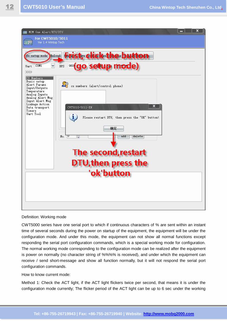
4.1.1 Preparation for operation and being under con figuration mode
Connect the equipment with the serial ports of the computer with power-on and open the configuration
software, make the equipment under the configuration mode according to the following figure.
Note: Please choose the serial port No. and rate correctly, the default communication rate is 9600
Tel: +86-755-26719943 | Fax: +86-755-26719940 | Web site: http://www.mobq2000.com
CWT5010 User’s Manual China Wintop Tech Shenzhen Co., Ltd .
1122
Definition: Working mode
CWT5000 series have one serial port to which if continuous characters of % are sent within an instant
time of several seconds during the power on startup of the equipment, the equipment will be under the
configuration mode. And under this mode, the equipment can not show all normal functions except
responding the serial port configuration commands, which is a special working mode for configuration.
The normal working mode corresponding to the configuration mode can be realized after the equipment
is power on normally (no character string of %%%% is received), and under which the equipment can
receive / send short-message and show all function normally, but it will not respond the serial port
configuration commands.
How to know current mode:
Method 1: Check the ACT light, if the ACT light flickers twice per second, that means it is under the
configuration mode currently; The flicker period of the ACT light can be up to 6 sec under the working
Tel: +86-755-26719943 | Fax: +86-755-26719940 | Web site: http://www.mobq2000.com
CWT5010 User’s Manual China Wintop Tech Shenzhen Co., Ltd .
1133
mode
Method 2: Check the startup information from the serial port, if the character string of “dtu come in setup
mode” occurs, it means that the equipment is under the configuration mode.
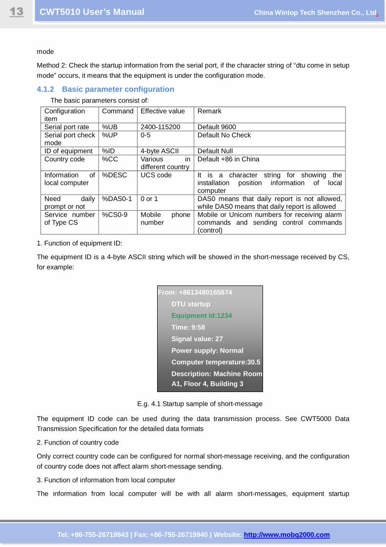
4.1.2 Basic parameter configuration The basic parameters consist of:
Configuration item
Command Effective value Remark
Serial port rate %UB 2400-115200 Default 9600 Serial port check mode
%UP 0-5 Default No Check
ID of equipment %ID 4-byte ASCII Default Null Country code %CC Various in
different country Default +86 in China
Information of local computer
%DESC UCS code It is a character string for showing the installation position information of local computer
Need daily prompt or not
%DAS0-1 0 or 1 DAS0 means that daily report is not allowed, while DAS0 means that daily report is allowed
Service number of Type CS
%CS0-9 Mobile phone number
Mobile or Unicom numbers for receiving alarm commands and sending control commands (control)
1. Function of equipment ID:
The equipment ID is a 4-byte ASCII string which will be showed in the short-message received by CS,
for example:
E.g. 4.1 Startup sample of short-message
The equipment ID code can be used during the data transmission process. See CWT5000 Data
Transmission Specification for the detailed data formats
2. Function of country code
Only correct country code can be configured for normal short-message receiving, and the configuration
of country code does not affect alarm short-message sending.
3. Function of information from local computer
The information from local computer will be with all alarm short-messages, equipment startup
From: +8613480165874
DTU startup
Equipment Id:1234
Time: 9:58
Signal value: 27
Power supply: Normal
Computer temperature:30.5
Description: Machine Room A1, Floor 4, Building 3
Tel: +86-755-26719943 | Fax: +86-755-26719940 | Web site: http://www.mobq2000.com
CWT5010 User’s Manual China Wintop Tech Shenzhen Co., Ltd .
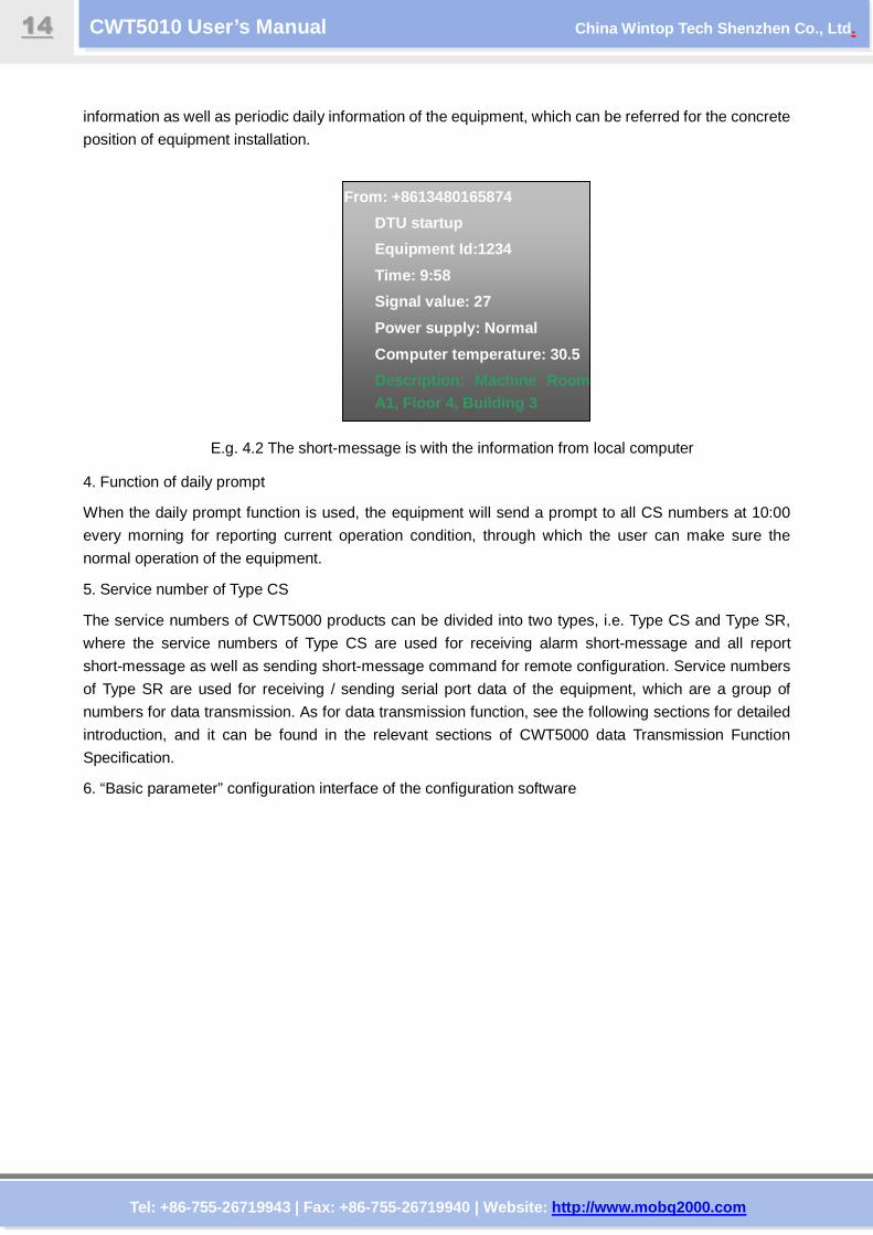
1144
information as well as periodic daily information of the equipment, which can be referred for the concrete
position of equipment installation.
E.g. 4.2 The short-message is with the information from local computer
4. Function of daily prompt
When the daily prompt function is used, the equipment will send a prompt to all CS numbers at 10:00
every morning for reporting current operation condition, through which the user can make sure the
normal operation of the equipment.
5. Service number of Type CS
The service numbers of CWT5000 products can be divided into two types, i.e. Type CS and Type SR,
where the service numbers of Type CS are used for receiving alarm short-message and all report
short-message as well as sending short-message command for remote configuration. Service numbers
of Type SR are used for receiving / sending serial port data of the equipment, which are a group of
numbers for data transmission. As for data transmission function, see the following sections for detailed
introduction, and it can be found in the relevant sections of CWT5000 data Transmission Function
Specification.
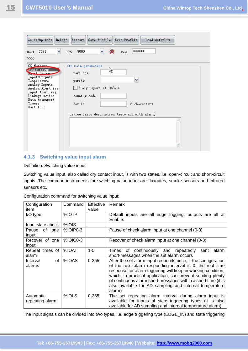
6. “Basic parameter” configuration interface of the configuration software
From: +8613480165874
DTU startup
Equipment Id:1234
Time: 9:58
Signal value: 27
Power supply: Normal
Computer temperature: 30.5
Description: Machine Room A1, Floor 4, Building 3
Tel: +86-755-26719943 | Fax: +86-755-26719940 | Web site: http://www.mobq2000.com
CWT5010 User’s Manual China Wintop Tech Shenzhen Co., Ltd .
1155
4.1.3 Switching value input alarm
Definition: Switching value input
Switching value input, also called dry contact input, is with two states, i.e. open-circuit and short-circuit
inputs. The common instruments for switching value input are fluxgates, smoke sensors and infrared
sensors etc.
Configuration command for switching value input:
Configuration item
Command Effective value
Remark
I/O type %IOTP Default inputs are all edge trigging, outputs are all at Enable.
Input state check %IOIS Pause of one input
%IOIP0-3 Pause of check alarm input at one channel (0-3)
Recover of one input
%IOIC0-3 Recover of check alarm input at one channel (0-3)
Repeat times of alarm
%IOAT 1-5 Times of continuously and repeatedly sent alarm short-messages when the set alarm occurs
Interval of alarms
%IOAS 0-255 After the set alarm input responds once, if the configuration of the next alarm responding interval is 0, the real time response for alarm triggering will keep in working condition, which, in practical application, can prevent sending plenty of continuous alarm short-messages within a short time (it is also available for AD sampling and internal temperature alarm)
Automatic repeating alarm
%IOLS 0-255 The set repeating alarm interval during alarm input is available for inputs of state triggering types (it is also available for AD sampling and internal temperature alarm)
The input signals can be divided into two types, i.e. edge triggering type (EDGE_IN) and state triggering
Tel: +86-755-26719943 | Fax: +86-755-26719940 | Web site: http://www.mobq2000.com
CWT5010 User’s Manual China Wintop Tech Shenzhen Co., Ltd .
1166
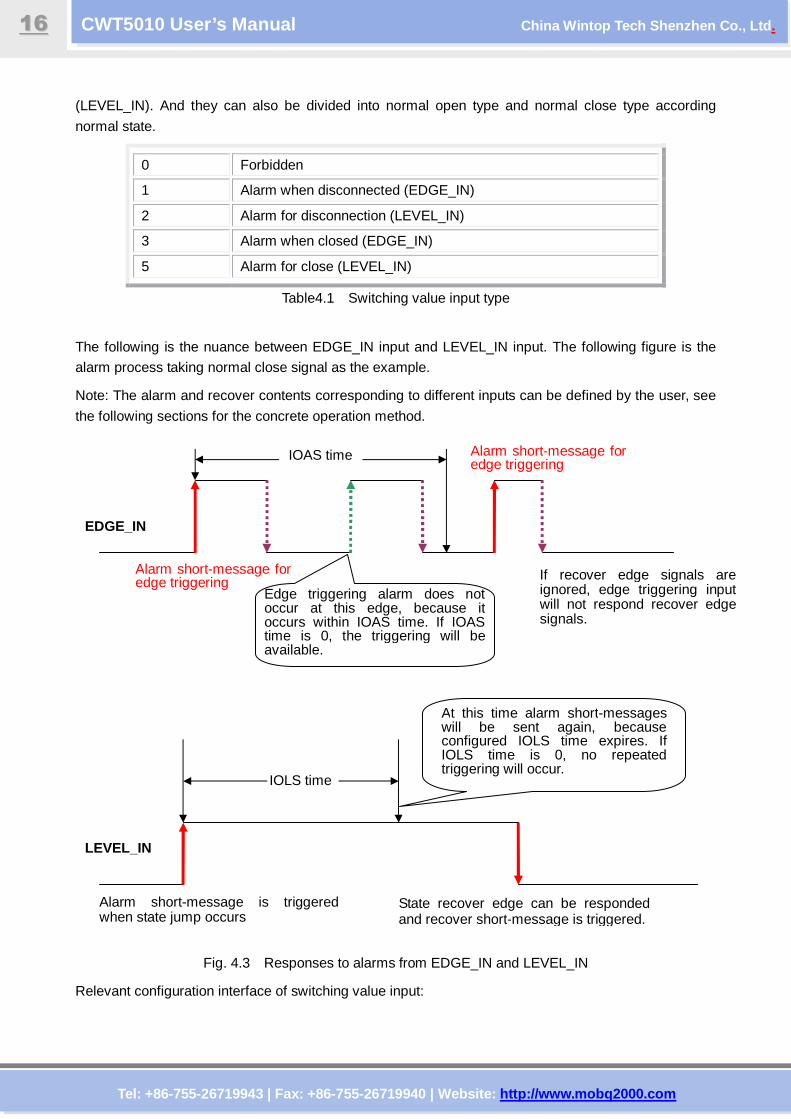
(LEVEL_IN). And they can also be divided into normal open type and normal close type according
normal state.
0 Forbidden
1 Alarm when disconnected (EDGE_IN)
2 Alarm for disconnection (LEVEL_IN)
3 Alarm when closed (EDGE_IN)
5 Alarm for close (LEVEL_IN)
Table4.1 Switching value input type
The following is the nuance between EDGE_IN input and LEVEL_IN input. The following figure is the
alarm process taking normal close signal as the example.
Note: The alarm and recover contents corresponding to different inputs can be defined by the user, see
the following sections for the concrete operation method.
Fig. 4.3 Responses to alarms from EDGE_IN and LEVEL_IN
Relevant configuration interface of switching value input:
Alarm short-message for edge triggering
Alarm short-message is triggered when state jump occurs
State recover edge can be responded and recover short-message is triggered.
If recover edge signals are ignored, edge triggering input will not respond recover edge signals.
Alarm short-message for edge triggering
Edge triggering alarm does not occur at this edge, because it occurs within IOAS time. If IOAS time is 0, the triggering will be available.
IOLS time
At this time alarm short-messages will be sent again, because configured IOLS time expires. If IOLS time is 0, no repeated triggering will occur.
EDGE_IN
LEVEL_IN
IOAS time
Tel: +86-755-26719943 | Fax: +86-755-26719940 | Web site: http://www.mobq2000.com
CWT5010 User’s Manual China Wintop Tech Shenzhen Co., Ltd .
1177
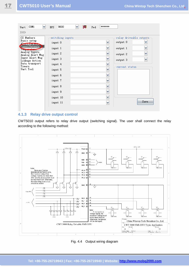
4.1.3 Relay drive output control
CWT5010 output refers to relay drive output (switching signal). The user shall connect the relay
according to the following method:
Fig. 4.4 Output wiring diagram
Tel: +86-755-26719943 | Fax: +86-755-26719940 | Web site: http://www.mobq2000.com
CWT5010 User’s Manual China Wintop Tech Shenzhen Co., Ltd .
1188
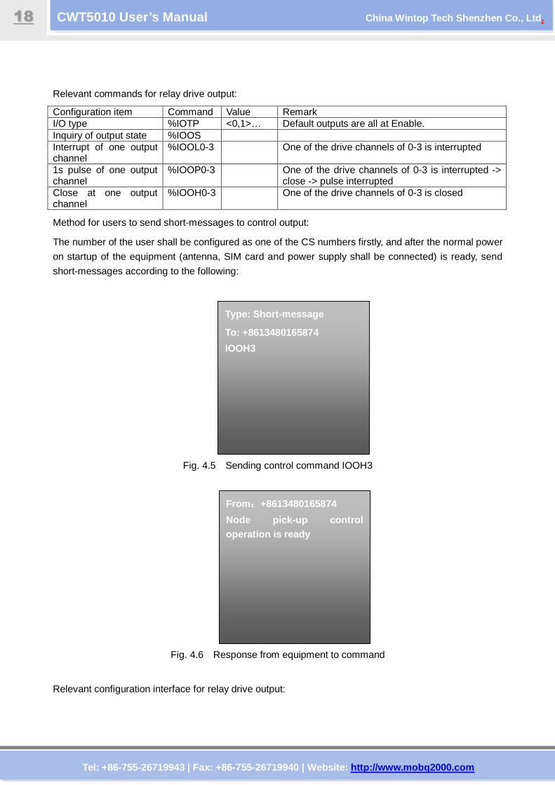
Relevant commands for relay drive output:
Configuration item Command Value Remark I/O type %IOTP <0,1>… Default outputs are all at Enable. Inquiry of output state %IOOS Interrupt of one output channel
%IOOL0-3 One of the drive channels of 0-3 is interrupted
1s pulse of one output channel
%IOOP0-3 One of the drive channels of 0-3 is interrupted -> close -> pulse interrupted
Close at one output channel
%IOOH0-3 One of the drive channels of 0-3 is closed
Method for users to send short-messages to control output:
The number of the user shall be configured as one of the CS numbers firstly, and after the normal power
on startup of the equipment (antenna, SIM card and power supply shall be connected) is ready, send
short-messages according to the following:
Fig. 4.5 Sending control command IOOH3
Fig. 4.6 Response from equipment to command
Relevant configuration interface for relay drive output:
From::::+8613480165874
Node pick-up control operation is ready
Type: Short-message
To: +8613480165874
IOOH3
Tel: +86-755-26719943 | Fax: +86-755-26719940 | Web site: http://www.mobq2000.com
CWT5010 User’s Manual China Wintop Tech Shenzhen Co., Ltd .
1199
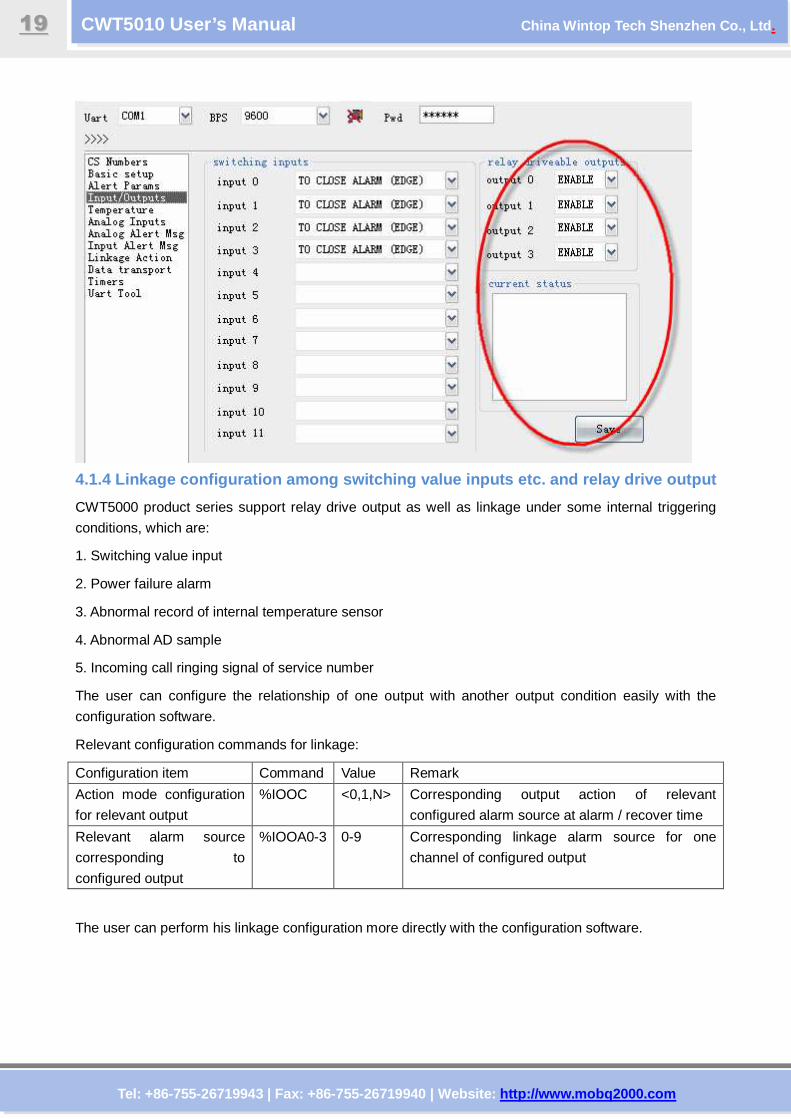
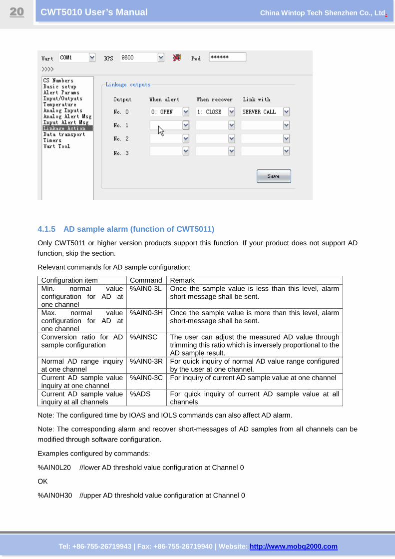
4.1.4 Linkage configuration among switching value i nputs etc. and relay drive output
CWT5000 product series support relay drive output as well as linkage under some internal triggering
conditions, which are:
1. Switching value input
2. Power failure alarm
3. Abnormal record of internal temperature sensor
4. Abnormal AD sample
5. Incoming call ringing signal of service number
The user can configure the relationship of one output with another output condition easily with the
configuration software.
Relevant configuration commands for linkage:
Configuration item Command Value Remark
Action mode configuration
for relevant output
%IOOC <0,1,N> Corresponding output action of relevant
configured alarm source at alarm / recover time
Relevant alarm source
corresponding to
configured output
%IOOA0-3 0-9 Corresponding linkage alarm source for one
channel of configured output
The user can perform his linkage configuration more directly with the configuration software.
Tel: +86-755-26719943 | Fax: +86-755-26719940 | Web site: http://www.mobq2000.com
CWT5010 User’s Manual China Wintop Tech Shenzhen Co., Ltd .
2200
4.1.5 AD sample alarm (function of CWT5011)
Only CWT5011 or higher version products support this function. If your product does not support AD
function, skip the section.
Relevant commands for AD sample configuration:
Configuration item Command Remark Min. normal value configuration for AD at one channel
%AIN0-3L Once the sample value is less than this level, alarm short-message shall be sent.
Max. normal value configuration for AD at one channel
%AIN0-3H Once the sample value is more than this level, alarm short-message shall be sent.
Conversion ratio for AD sample configuration
%AINSC The user can adjust the measured AD value through trimming this ratio which is inversely proportional to the AD sample result.
Normal AD range inquiry at one channel
%AIN0-3R For quick inquiry of normal AD value range configured by the user at one channel.
Current AD sample value inquiry at one channel
%AIN0-3C For inquiry of current AD sample value at one channel
Current AD sample value inquiry at all channels
%ADS For quick inquiry of current AD sample value at all channels
Note: The configured time by IOAS and IOLS commands can also affect AD alarm.
Note: The corresponding alarm and recover short-messages of AD samples from all channels can be
modified through software configuration.
Examples configured by commands:
%AIN0L20 //lower AD threshold value configuration at Channel 0
OK
%AIN0H30 //upper AD threshold value configuration at Channel 0
Tel: +86-755-26719943 | Fax: +86-755-26719940 | Web site: http://www.mobq2000.com
CWT5010 User’s Manual China Wintop Tech Shenzhen Co., Ltd .
2211
OK
%AIN0R //inquiry for normal AD threshold value range at Channel 0
20-30mA
OK
%AIN0C //inquiry current AD value at Channel 0
28mA
OK
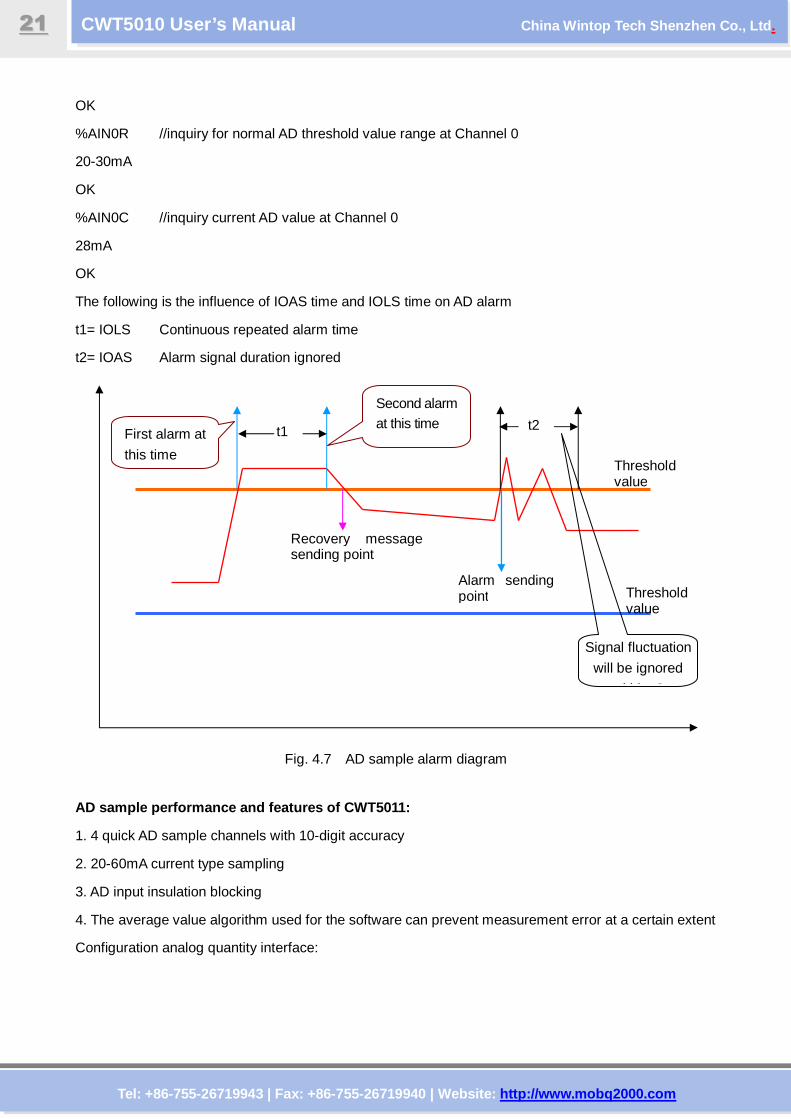
The following is the influence of IOAS time and IOLS time on AD alarm
t1= IOLS Continuous repeated alarm time
t2= IOAS Alarm signal duration ignored
Fig. 4.7 AD sample alarm diagram
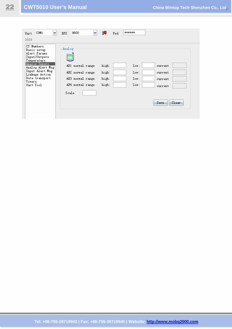
AD sample performance and features of CWT5011:
1. 4 quick AD sample channels with 10-digit accuracy
2. 20-60mA current type sampling
3. AD input insulation blocking
4. The average value algorithm used for the software can prevent measurement error at a certain extent
Configuration analog quantity interface:
t1 First alarm at
this time
Second alarm at this time
Threshold value
Threshold value
Alarm sending point
Recovery message sending point
t2
Signal fluctuation
will be ignored
within t2
Tel: +86-755-26719943 | Fax: +86-755-26719940 | Web site: http://www.mobq2000.com
CWT5010 User’s Manual China Wintop Tech Shenzhen Co., Ltd .
2222
Tel: +86-755-26719943 | Fax: +86-755-26719940 | Web site: http://www.mobq2000.com
CWT5010 User’s Manual China Wintop Tech Shenzhen Co., Ltd .
2233
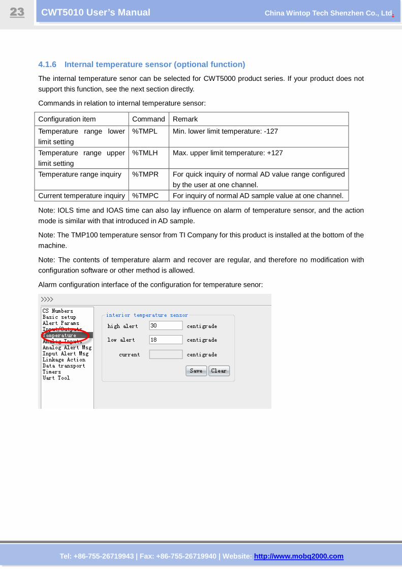
4.1.6 Internal temperature sensor (optional functi on)
The internal temperature senor can be selected for CWT5000 product series. If your product does not
support this function, see the next section directly.
Commands in relation to internal temperature sensor:
Configuration item Command Remark
Temperature range lower
limit setting
%TMPL Min. lower limit temperature: -127
Temperature range upper
limit setting
%TMLH Max. upper limit temperature: +127
Temperature range inquiry %TMPR For quick inquiry of normal AD value range configured
by the user at one channel.
Current temperature inquiry %TMPC For inquiry of normal AD sample value at one channel.
Note: IOLS time and IOAS time can also lay influence on alarm of temperature sensor, and the action
mode is similar with that introduced in AD sample.
Note: The TMP100 temperature sensor from TI Company for this product is installed at the bottom of the
machine.
Note: The contents of temperature alarm and recover are regular, and therefore no modification with
configuration software or other method is allowed.
Alarm configuration interface of the configuration for temperature senor:
Tel: +86-755-26719943 | Fax: +86-755-26719940 | Web site: http://www.mobq2000.com
CWT5010 User’s Manual China Wintop Tech Shenzhen Co., Ltd .
2244
4.1.7 Power-off alarm (optional function)
The internal secondary battery can be selected for CWT5000 product series. If your product does not
support this function, see the next section directly.
Command in relation to battery alarm:
Configuration item Command Remark
Current power supply condition inquiry %POW Current power supply condition inquiry
Battery parameter:
Lithium battery
Voltage: 3.7V
Capacity: 450mAh
Limited voltage for charging 4.2V
Implementation standard GB/T 18287-2000
Note: The contents of power-off alarm is regular, and therefore no modification with configuration
software or other method is allowed.
4.1.8 Buzzer alarm (function of CWT5011)
A buzzer is installed in the CWT5011 product. When AD sample fails or internal temperature alarm
occurs during switching value, the buzzer will be activated, which can be stopped by the buzzer reset
button on the equipment panel, or through sending the command of BUZCLR with CS number remotely.
Command in relation to buzzer:
Configuration item Command Remark
Stop buzzer %BUZCLR
Start buzzer %BUZSET Triggering buzzer alarm command by hand
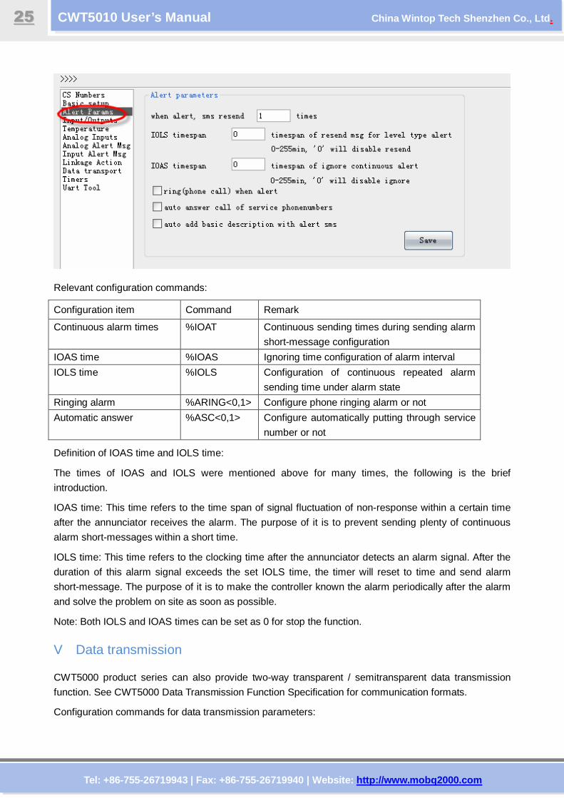
4.1.9 Relevant parameter configuration for alarm mo des
The relevant parameter configuration interface for alarm modes for the configuration software is as
follows:
Tel: +86-755-26719943 | Fax: +86-755-26719940 | Web site: http://www.mobq2000.com
CWT5010 User’s Manual China Wintop Tech Shenzhen Co., Ltd .
2255
Relevant configuration commands:
Configuration item Command Remark
Continuous alarm times %IOAT Continuous sending times during sending alarm
short-message configuration
IOAS time %IOAS Ignoring time configuration of alarm interval
IOLS time %IOLS Configuration of continuous repeated alarm
sending time under alarm state
Ringing alarm %ARING<0,1> Configure phone ringing alarm or not
Automatic answer %ASC<0,1> Configure automatically putting through service
number or not
Definition of IOAS time and IOLS time:
The times of IOAS and IOLS were mentioned above for many times, the following is the brief
introduction.
IOAS time: This time refers to the time span of signal fluctuation of non-response within a certain time
after the annunciator receives the alarm. The purpose of it is to prevent sending plenty of continuous
alarm short-messages within a short time.
IOLS time: This time refers to the clocking time after the annunciator detects an alarm signal. After the
duration of this alarm signal exceeds the set IOLS time, the timer will reset to time and send alarm
short-message. The purpose of it is to make the controller known the alarm periodically after the alarm
and solve the problem on site as soon as possible.
Note: Both IOLS and IOAS times can be set as 0 for stop the function.
V Data transmission
CWT5000 product series can also provide two-way transparent / semitransparent data transmission
function. See CWT5000 Data Transmission Function Specification for communication formats.
Configuration commands for data transmission parameters:
Tel: +86-755-26719943 | Fax: +86-755-26719940 | Web site: http://www.mobq2000.com
CWT5010 User’s Manual China Wintop Tech Shenzhen Co., Ltd .
2266
Configuration item Command Remark
Service No. %SR0-9 Service number configuration for data transmission
target
Transmission mode %TM0-5 Data transmission mode configuration
Data overtime %OT Data receiving overtime configuration
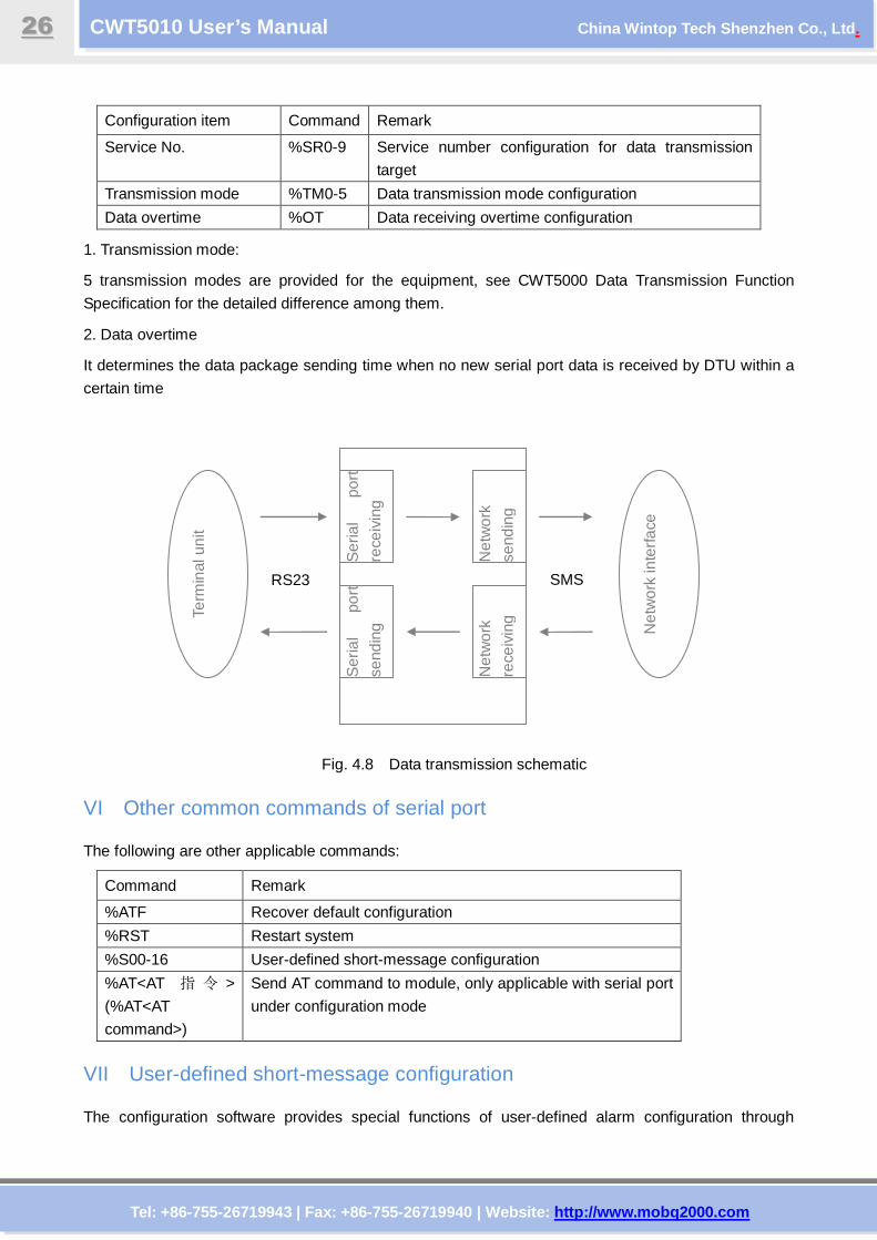
1. Transmission mode:
5 transmission modes are provided for the equipment, see CWT5000 Data Transmission Function
Specification for the detailed difference among them.
2. Data overtime
It determines the data package sending time when no new serial port data is received by DTU within a
certain time
Fig. 4.8 Data transmission schematic
VI Other common commands of serial port
The following are other applicable commands:
Command Remark
%ATF Recover default configuration
%RST Restart system
%S00-16 User-defined short-message configuration
%AT<AT 指 令 >
(%AT<AT
command>)
Send AT command to module, only applicable with serial port
under configuration mode
VII User-defined short-message configuration
The configuration software provides special functions of user-defined alarm configuration through
Ser
ial
port
rece
ivin
g
Ser
ial
port
send
ing
Net
wor
k
send
ing
Net
wor
k
rece
ivin
g Term
inal
uni
t
Net
wor
k in
terf
ace
RS23 SMS
Tel: +86-755-26719943 | Fax: +86-755-26719940 | Web site: http://www.mobq2000.com
CWT5010 User’s Manual China Wintop Tech Shenzhen Co., Ltd .
2277
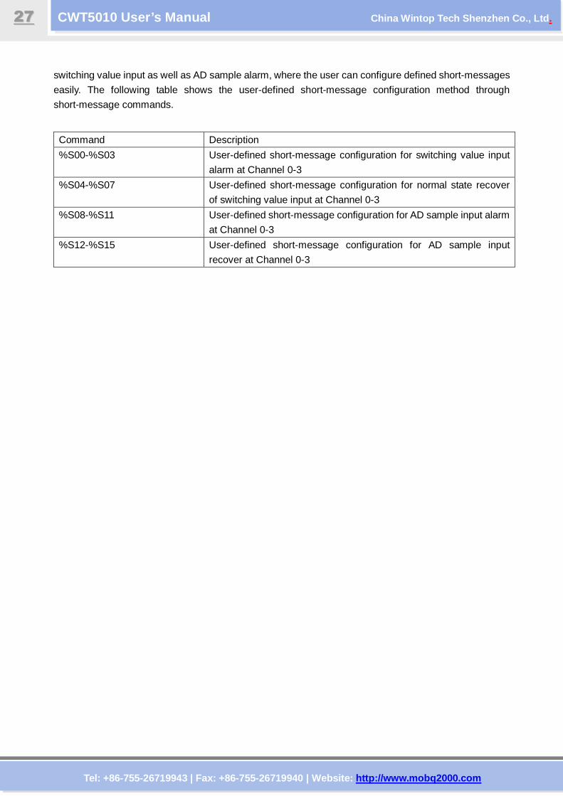
switching value input as well as AD sample alarm, where the user can configure defined short-messages
easily. The following table shows the user-defined short-message configuration method through
short-message commands.
Command Description
%S00-%S03 User-defined short-message configuration for switching value input
alarm at Channel 0-3
%S04-%S07 User-defined short-message configuration for normal state recover
of switching value input at Channel 0-3
%S08-%S11 User-defined short-message configuration for AD sample input alarm
at Channel 0-3
%S12-%S15 User-defined short-message configuration for AD sample input
recover at Channel 0-3
Tel: +86-755-26719943 | Fax: +86-755-26719940 | Web site: http://www.mobq2000.com
CWT5010 User’s Manual China Wintop Tech Shenzhen Co., Ltd .
2288
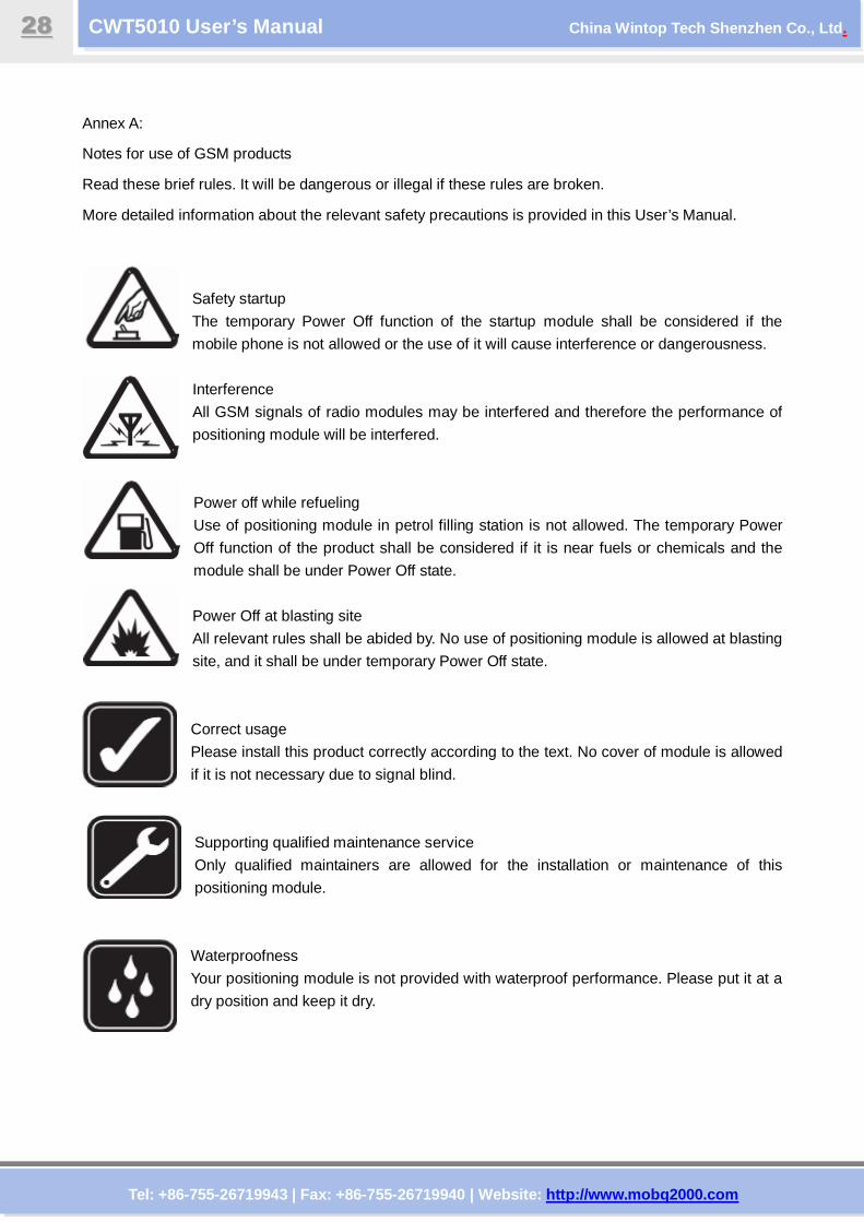
Annex A:
Notes for use of GSM products
Read these brief rules. It will be dangerous or illegal if these rules are broken.
More detailed information about the relevant safety precautions is provided in this User’s Manual.
Safety startup
The temporary Power Off function of the startup module shall be considered if the
mobile phone is not allowed or the use of it will cause interference or dangerousness.
Interference
All GSM signals of radio modules may be interfered and therefore the performance of
positioning module will be interfered.
Power off while refueling
Use of positioning module in petrol filling station is not allowed. The temporary Power
Off function of the product shall be considered if it is near fuels or chemicals and the
module shall be under Power Off state.
Power Off at blasting site
All relevant rules shall be abided by. No use of positioning module is allowed at blasting
site, and it shall be under temporary Power Off state.
Correct usage
Please install this product correctly according to the text. No cover of module is allowed
if it is not necessary due to signal blind.
Supporting qualified maintenance service
Only qualified maintainers are allowed for the installation or maintenance of this
positioning module.
Waterproofness
Your positioning module is not provided with waterproof performance. Please put it at a
dry position and keep it dry.