Embed Size (px)
Citation preview

1908S20000CV
Grand Rapids, Michigan, U.S.A. 49504-5298
USER’S OPERATING AND INSTRUCTION MANUAL
MODEL 1908
AUTOMATED PACKAGING SYSTEM

11/12/09 1908S20001 1-1
INDEX
QUICK SPECS…...……………………...……………………………… PG. 1-2 INTRODUCTION AND DESCRIPTION………………………………. PG. 1-3 UNCRATING…………………………………………………………….. PG. 1-4 SAFETY..............................................……………………..………….. PG. 1-8 MACHINE PLACEMENT………………………………………..……… PG. 1-9 MACHINE COMPONENTS…………………………………………….. PG. 1-12 START-UP……………………………………………………………….. PG. 1-17 OPERATING PROCEDURE............................................................. PG. 1-20 TECHNICAL SPECIFICATIONS....................................................... PG. 1-24 CLEANING AND MAINTENANCE....................…..............…........... PG. 1-26 TROUBLE SHOOTING......................................…......................….. PG. 1-31 MAINTENANCE CHECKLIST……....................…..............….......... PG. 2-1 ASSEMBLY DRAWINGS & PARTS LISTS..………………………... PG. 3-1 ELECTRICAL……………………………………………………………. PG. 4-1 PNEUMATIC.…………..………………………………………………… PG. 5-1 MACHINE EXCHANGE PROGRAM………… GEN 050815 WARRANTY...................…............................. GEN 050816 WARRANTY PROCEDURE..........….............. GEN 050817 RETURNED PARTS POLICY......................... GEN 050818

11/12/09 1908S20001 1-2
QUICK SPECS
Weight 300 lbs Overall Dimensions 30” W x 64” L x 50” H Loading Station 3 tray carriers Electrical 1 phase, 60 hz, 115 VAC, 15 amps Air Supply 90 psi ± 10 psi Air Connector Size ¼” Air Compressor: Electrical 1 phase, 60 hz, 115/230 VAC, 1.7 run HP, 13 GAL tank Dimensions 16.625” W x 30.5” L x 33.75” H Weight 60 lbs Length of Air Hose 70 ft Air Hose I.D. 3/8”

11/12/09 1908S20001 1-3
INTRODUCTION AND DESCRIPTION
The OLIVER Model 1908 Lidder has been designed and manufactured to provide a high quality machine that is a cost effective approach to producing film lidded trays. The machine can be operated with a 120 V.A.C. outlet. The Model 1908 is an automated system capable of producing a high volume, but it is easy to operate and requires minimal space. The machine consists of a conveyor system that transports the filled trays, a film feed system, a heated platen and a film cutter unit. These are all packaged together in a stainless steel framework that also houses all the necessary controls. The conveyor is intermittent motion and is capable of running speeds of 5 to 35 packages per minute. The system also includes an air compressor that is a separate unit that can be located remotely.

11/12/09 1908S20001 1-4
INSPECTING
MODEL 1908
Upon receipt of Machine, inspect the exterior for damage. If damage is noted, Indicate damage on the Freight Bill and immediately contact the freight Carrier and notify them of the damage. Have a freight claim filed. This must be done at the Recipient’s location and not at the Shipper’s Location.
Remove the tie-downs that hold the Trays from moving. Cut bands that hold the 1908 Machine and the Air Compressor on the skid. Lift the Air Compressor and then the Machine off the skid in a safe manner.

11/12/09 1908S20001 1-5
SAFETY
Various safety devices and methods of guarding have been provided on this machine. Do not operate the machine with guards removed and do not tamper with safety devices. It is essential that machine operators and maintenance personnel observe the following safety precautions. Improper installation or operation of this equipment may cause injury to personnel or damage to equipment. • Before operating the OLIVER Model 1908 Lidder read through this manual. Never
allow an untrained person to operate this machine
WARNING • WARNING PINCH POINT: Keep hands out of machine. Always be sure the
machine has been unplugged from power before cleaning or servicing.
• CAUTION HOT: The heater cover and upper platen are very HOT! Caution must
be used to protect yourself and others.
• In addition to these general safety instructions, follow the specific instructions given
throughout this manual.

11/12/09 1908S20001 1-6
MACHINE PLACEMENT AND UTILITIES
MODEL 1908
Decide on a suitable location for the machine. This location should have ample room to work around all sides of the machine. Once the machine is in the location where it will be used, the brakes on the casters should be locked by stepping down on the brake locking lever. To unlock, lift the lever with your foot. Do not attempt to move machine with casters in locked position.
The machine operates on 120 V.A.C., 60 Hz, 15 Amp electrical power. It is recommended that this power be supplied by an overhead drop to prevent the cord from becoming a trip hazard. The machine needs to be connected to compressed air. This is accomplished by connecting the machine to the air compressor supplied with the machine. This connection should be made using an overhead drop.
LOCKING LEVER
11/12/09 1908S20001 1-7
Air Compressor
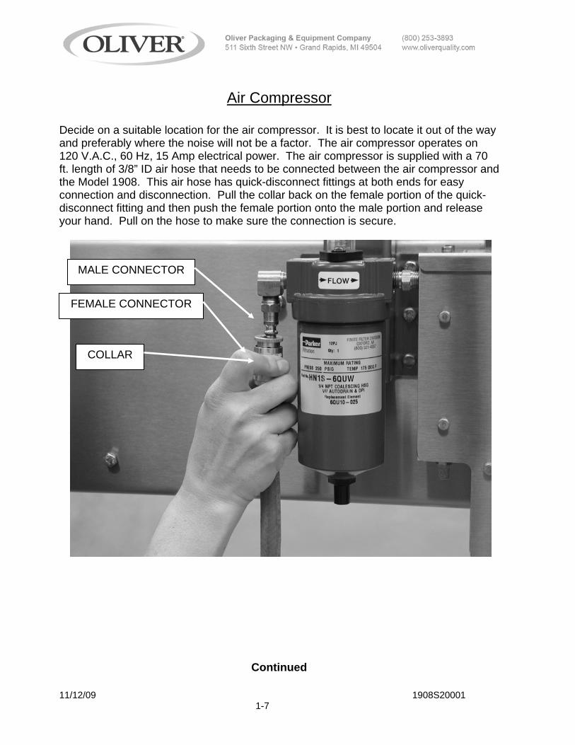
Decide on a suitable location for the air compressor. It is best to locate it out of the way and preferably where the noise will not be a factor. The air compressor operates on 120 V.A.C., 60 Hz, 15 Amp electrical power. The air compressor is supplied with a 70 ft. length of 3/8” ID air hose that needs to be connected between the air compressor and the Model 1908. This air hose has quick-disconnect fittings at both ends for easy connection and disconnection. Pull the collar back on the female portion of the quick-disconnect fitting and then push the female portion onto the male portion and release your hand. Pull on the hose to make sure the connection is secure.
Continued
MALE CONNECTOR
FEMALE CONNECTOR
COLLAR

11/12/09 1908S20001 1-8
Air Compressor Continued
The air compressor has been factory set. If for some reason the settings are not correct, the following procedure should be followed to set the output pressure from the compressor. The gage shown below should be set at 80 PSI. This is accomplished by turning the knob on the regulator clockwise to increase pressure or counter clockwise to decrease pressure. It is recommended that the air compressor be left with the switch in the “AUTO” position. The compressor will only run when there is a demand for air when it is set in the “AUTO” position. Leaving the switch in this position assures that the compressor will be ready when it is needed.

11/12/09 1908S20001 1-9
MACHINE COMPONENTS
Before proceeding further, take a moment to familiarize yourself with the identification of the machine components as shown in the illustrations below.
HEAT SEAL DWELL TIMER
FILTER REPLACEMENT
INDICATOR
FILTER OK / REPLACE
LABELS
FILTER BRACKET

11/12/09 1908S20001 1-10
SPEED ADJUSTMENT-TURN CLOCKWISE TO SLOW DOWN TURN COUNTER CLOCKWISE TO SPEED UP
LOCKING NUT
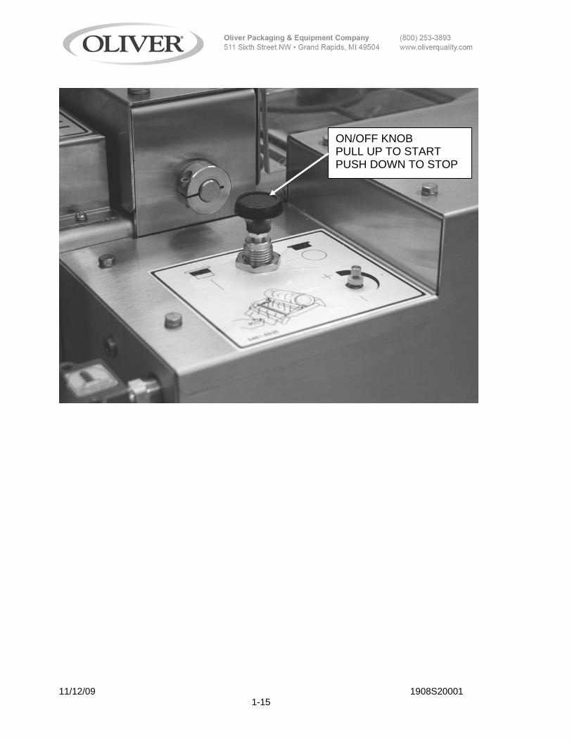
ON/OFF KNOB PULL UP TO START
PUSH DOWN TO STOP
11/12/09 1908S20001 1-11
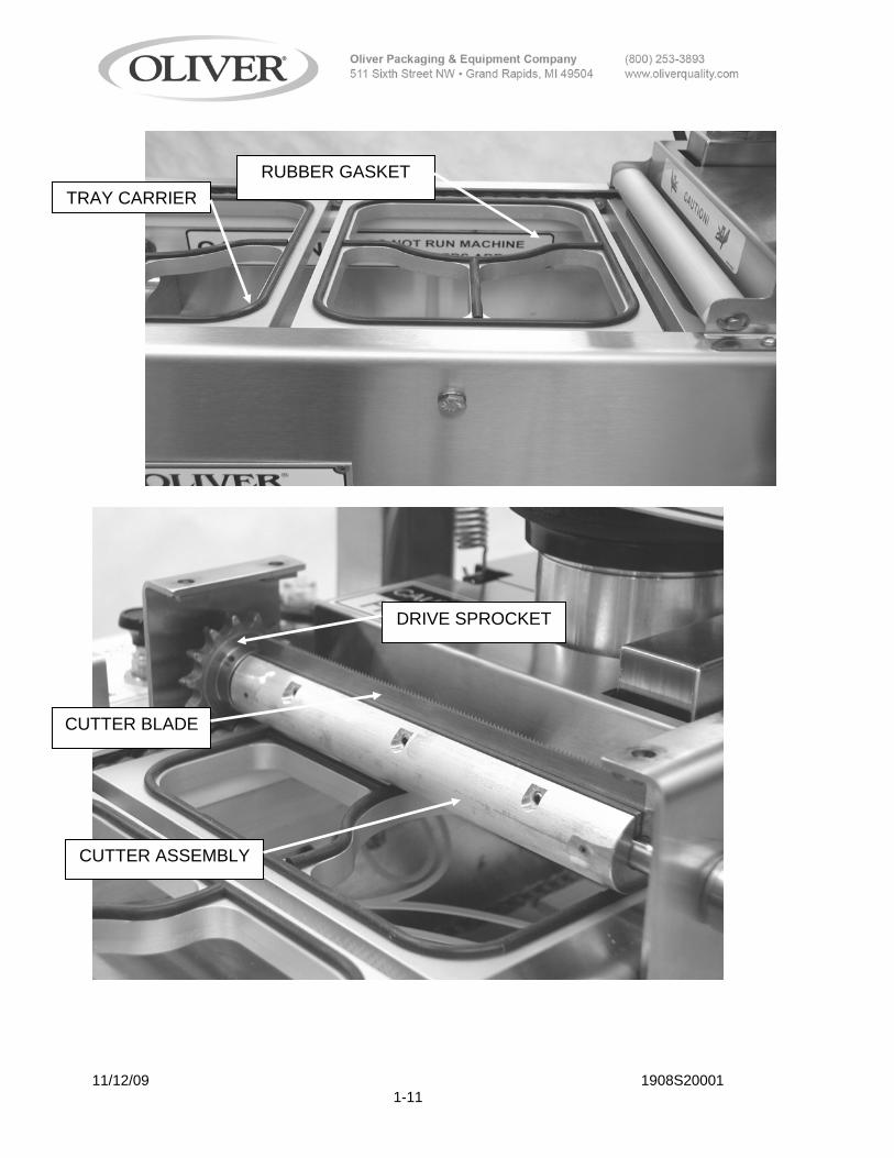
TRAY CARRIER RUBBER GASKET
CUTTER ASSEMBLY
CUTTER BLADE
DRIVE SPROCKET

11/12/09 1908S20001 1-12
DISCHARGE TABLE
WING NUTS LOOSEN TO ADJUST TABLE UP OR DOWN
TAKE-UP DEVICE
ADJUSTMENT SCREW
LOCKING NUT
THESE WING NUTS ALLOW FOR MOVING THE DISCHARGE TABLE IN AND OUT TO CLEAR THE TRAY CARRIERS

11/12/09 1908S20001 1-13
START-UP
To turn the machine on, plug in the power cord. Wait 30 minutes to allow the heated platen to reach operating temperature. At this time, turn on the air compressor so it can fill the storage tank with compressed air. The machine has been shipped from the factory with the speed set at approximately 7 to 10 trays per minute. This speed has been chosen as a good place to start. Depending on your production rates, you may need to speed up or slow down the tray sealer. This adjustment is explained in the “Machine Operation” section of the manual. First, run the machine without trays and film to make sure everything is cycling properly.
NOTE • Never run the machine with trays and no film. Doing so can possibly cause a jam
because the trays can stick to the heated platen and be pulled out of the tray carriers.
Load the film on the film stand as shown on the film-threading diagram located on the side of the machine and also shown in the diagram below.

11/12/09 1908S20001 1-14
NOTE
1. The adhesive side of the film can be determined by pinching a fold and rubbing the
lid material against itself. Test both sides of the lid. The rough or tacky side of the lid will be the adhesive side. The film supplied by Oliver Products Company is wound with the adhesive side toward the inside of the roll. If the film is loaded in accordance with the “FILM FEED” diagram it will be positioned properly for applying the adhesive side of the film to the flange of the tray. If the film is loaded improperly, it can cause the adhesive side to come in contact with the heated platen and the film to stick to the heated platen. If this happens, the platen will need to be cleaned.
2. To thread the film through the machine, pull enough film off the roll so that you can
insert it into the slot between the tray carrier that is partially under the film stand and the carrier that is upstream from that. After the film is hanging down underneath the tray carrier, reach through the tray carrier and pull the film down so that it touches the tray carriers underneath that are returning to come back up on top. Then insert a tray into the tray carrier next to the film and cycle the machine one time by pulling up on the “Black Palm Button” until the conveyor moves one index, then push the palm button down to stop the machine. This should seal the film to that tray and you can now fill the rest of the conveyor with filled trays and begin running.
Note: Film dancer bar must move freely up and down.
PULL FILM DOWN SO THAT IT TOUCHES THE TRAY CARRIER UNDERNEATH
FILM DANCER BAR,
11/12/09 1908S20001 1-15
ON/OFF KNOB PULL UP TO START PUSH DOWN TO STOP

11/12/09 1908S20001 1-16
OPERATING PROCEDURE
An abbreviated version of these operating procedures is attached to the Model 1908 for use as a daily reference. If you miss putting a tray in the machine it will not cause any problems, but the film will be sealed to the top of the empty tray carrier. Let the machine continue to run until that tray carrier goes around the bottom of the conveyor and comes back up on top, then remove the piece of film. Once you have settled into a fairly consistent production rate, adjust the machine speed to match your production rate as close as possible and lock the speed adjustment knob with the locknut. To operate the Model 1908, plug in the power cord. Wait 30 minutes to allow the heated platen to reach operating temperature. Turn on the air compressor.
1. Load a toll of film onto the film support stand as shown on the “FILM FEED” diagram located on the side of the machine. It is important that the roll of film is centered on the conveyor. There are white plastic film guides on either side of the film roll. These guides can be adjusted from side-to-side by pushing them with your hand. If the film is not centered, move both guides toward the side that the film needs to go to. It may take a little bit of running time before you can tell if the film is in the correct position.
2. To get the film threaded through the machine, pull enough film off the roll so that
you can insert it in the slot between the tray carrier that is partially under the film stand and the carrier that is upstream from that. After the film is hanging down underneath the tray carrier, reach through the tray carrier and pull the film down so that it touches the tray carriers underneath that are returning to come back up on top. Then insert a tray in the tray carrier next to the film and cycle the machine one time by pulling up on the “Black Palm Button” until the conveyor moves one index, then push the palm button down to stop the machine. This should seal the film to that tray and you can now fill the rest of the conveyor with the filled trays and begin running.
3. Place filled trays in tray carriers. Take care to avoid spilling food product on the
flange of the tray. Contamination of the flange can result in poor heat seals.

11/12/09 1908S20001 1-17
NOTE
• Never run the machine with trays and no film. Doing so can possibly cause a jam because the trays can stick to the heated platen and be pulled out of the tray carriers.
4. Pull the black palm button up to start the machine running. After a few trays
come out of the machine, stop and check to see that the seals are acceptable. Poor seals may be caused if the dwell time of heated platen is set too short. The machine was shipped from the factory with the dwell time set properly. However, it could have come out of adjustment during shipment. The 0.1-3 second dwell time adjustment knob should be set with indicator arrow between the letter “B & C” as shown in the illustration below. Do not turn the knob so that the indicator arrow goes past the letter “F” and before the letter “A”. The closer the indicator arrow is to the “A”, the shorter the dwell time.
NOTE
• Dwell timer with (0.1-30s) should be set between A &B. The indicator arrow should not be turned past these letters.
INDICATOR ARROW

11/12/09 1908S20001 1-18
NOTE
• The machine can be stopped at any time by pushing the black palm button down. When started again, the machine will pick up sealing where it left off.
5. Once you are running at a constant rate, set the speed of the machine to match
your production rate. This is done by turning the “Speed Adjustment” knob clockwise to slow the machine down or counterclockwise to speed the machine up. A locking nut is provided on the speed adjustment knob that can be used to lock the speed adjustment after you have found the desired setting.
6. Make certain that the sealed trays are discharging off the end of the machine
smoothly. If they are not, raise or lower your accumulating table or conveyor to allow for a smooth discharge of the trays. The discharge table on the Model 1908 has a height adjustment. The discharge table should be set at the proper height so that the bottoms of the trays are just slightly above it as they leave the tray carriers.
7. At the end of the day, unplug the Model 1908 from the wall outlet. This is the
only way to turn off the machine.
Discharge table
11/12/09 1908S20001 1-19
NOTE
• IT IS NOT RECOMMENDED TO LEAVE THE MACHINE PLUGGED IN WHEN IT IS GOING TO BE OUT OF OPERATION FOR AN EXTENDED PERIOD OF TIME.
TECHNICAL SPECIFICATIONS
Model 1908 Tray Capacities: 6-3/8” (162mm) by 8.5” (216mm) maximum top-outside-dimensions of the tray. Temperature Range: Factory preset to approx. 300 degrees F. Weight: 300 LBS. Electrical: 120 VAC, 15 Amps, Single Phase, and 60 Hz Air Requirements: 6 CFM @ 80 PSI

11/12/09 1908S20001 1-20
Machine Dimensions
17”
34”
64”
45”

11/12/09 1908S20001 1-21
Air Compressor
Weight: 60 LBS. Electrical: 115 VAC, 15 Amps, Single Phase, and 60 Hz Length of Air Hose: 70 Ft. Air Hose I.D.: 3/8” Air Connector Size: ¼” NPT Oil: Use a full synthetic motor oil like Mobil-1 10w -30 DO NOT USE REGULAR AUTOMOTIVE OIL SUCH AS 10W-30
Air Compressor Dimensions

11/12/09 1908S20001 1-22
CLEANING AND MAINTENANCE
Disconnect the power from the Model 1908 and allow the unit to cool before cleaning. The tray carriers should be removed and cleaned daily. It is better to remove them for cleaning rather than trying to clean them in the machine. The tray carriers can be placed in your dishwasher for cleaning if you desire. Care should be taken so that the rubber gaskets do not become damaged.
CAUTION • Do NOT run the machine with the tray carriers removed. Doing so could cause
damage to the heat seal assembly. The diagram on the next page shows how to remove the tray carriers. It is a simple process that just requires lifting up on the tray carrier and shifting it over to one side while pulling the carrier next to it to the other side to disengage the pins on the opposite side and then completely removing the carrier as shown. The carriers should be removed in the middle of the in-feed area on the top of the conveyor. As the carriers are removed, the conveyor must be pulled forward to keep getting to the remaining carriers. To move the conveyor forward, grasp a tray carrier toward the infeed-end of the machine and pull the conveyor forward. This must be done with the air connected.
NOTE • When replacing the tray carriers, it is extremely import to make sure that all four pins
on the conveyor chains are fully engaged in the holes of the tray carrier. If the tray carriers are put in on an angle because the pins are not engaged on one side, it could cause damage to the cutter assembly.

11/12/09 1908S20001 1-23
REMOVING TRAY CARRIERS
NOTE
• These cleaning recommendations are not meant to replace or supersede plant-standard manufacturing procedures or regulatory requirements.
• If the machine has been operating, allow the unit to cool before cleaning.
CAUTION • CAUTION HOT: The heater cover and upper platen are very HOT! Care must be
taken to protect yourself and others.
11/12/09 1908S20001 1-24
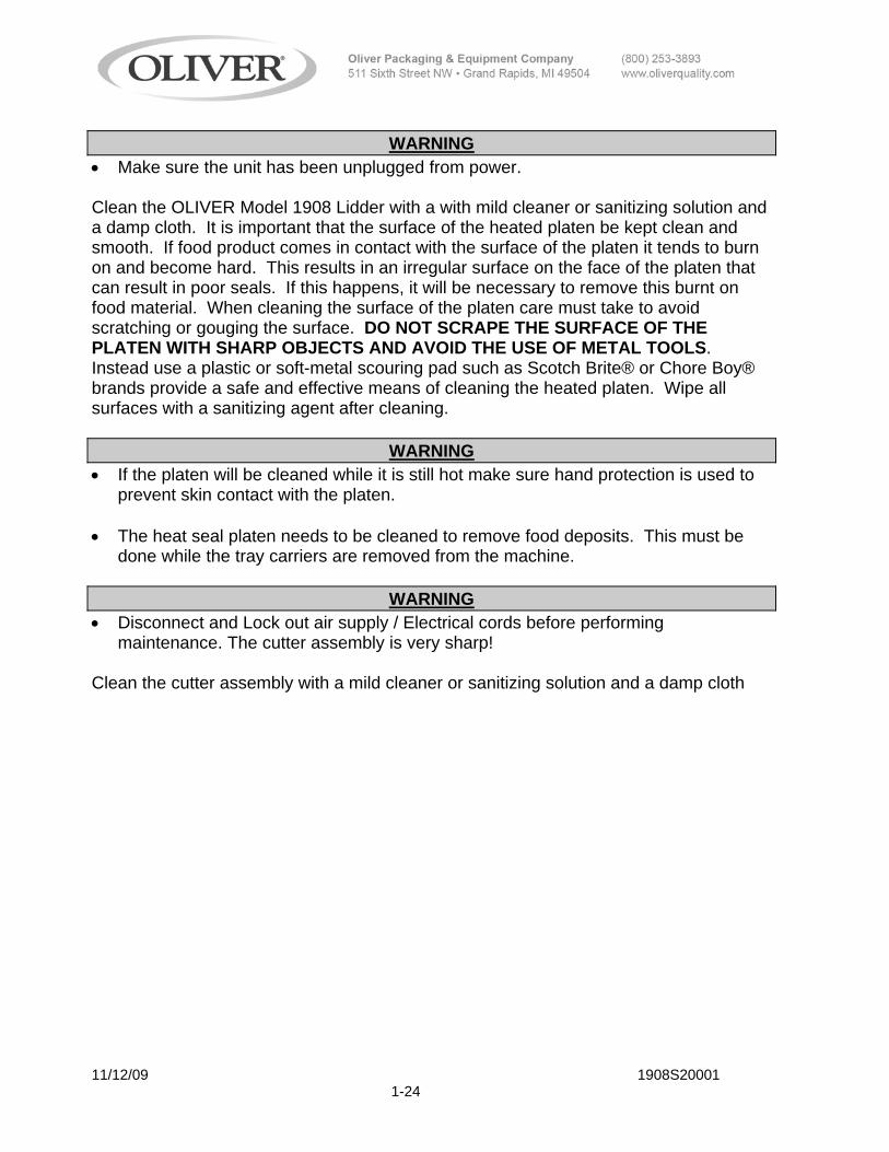
WARNING
• Make sure the unit has been unplugged from power. Clean the OLIVER Model 1908 Lidder with a with mild cleaner or sanitizing solution and a damp cloth. It is important that the surface of the heated platen be kept clean and smooth. If food product comes in contact with the surface of the platen it tends to burn on and become hard. This results in an irregular surface on the face of the platen that can result in poor seals. If this happens, it will be necessary to remove this burnt on food material. When cleaning the surface of the platen care must take to avoid scratching or gouging the surface. DO NOT SCRAPE THE SURFACE OF THE PLATEN WITH SHARP OBJECTS AND AVOID THE USE OF METAL TOOLS. Instead use a plastic or soft-metal scouring pad such as Scotch Brite® or Chore Boy® brands provide a safe and effective means of cleaning the heated platen. Wipe all surfaces with a sanitizing agent after cleaning.
WARNING • If the platen will be cleaned while it is still hot make sure hand protection is used to
prevent skin contact with the platen. • The heat seal platen needs to be cleaned to remove food deposits. This must be
done while the tray carriers are removed from the machine.
WARNING • Disconnect and Lock out air supply / Electrical cords before performing
maintenance. The cutter assembly is very sharp! Clean the cutter assembly with a mild cleaner or sanitizing solution and a damp cloth

11/12/09 1908S20001 1-25
NOTE
• The use of plastic or soft-metal scouring pads such as Scotch Brite® or Chore Boy® brands provide a safe and effective means of cleaning the cutter assembly. Wipe all surfaces with a sanitizing agent after cleaning.
Once a month the conveyor chains should be lubricated with vegetable oil such as cooking spray. If you use hose-down cleaning, this should be done twice a month.
Once a month the conveyor chains should be checked for proper tension. The tension can be checked by lifting the lower tray carriers at the middle of the machine. If you can easily lift them up more than 3 inches, the chains are too loose and should be tightened by adjusting the tensioners at the infeed-end of the machine. Loosen the locking nuts and turn the adjusting screws clockwise to tighten the chains then retighten the locking nut. It is important to adjust both sides equally. The easiest way to do this is to count the turns that you tighten one side and then do the same on the other side. The best method is to adjust each side in ¼ turn increments and then recheck the chain tension.
SPRAY CHAINS WHILE MACHINE IS CYCLING

11/12/09 1908S20001 1-26
ADJUSTING SCREW
LOCKING NUT

11/12/09 1908S20001 1-27
TROUBLESHOOTING
There are no user serviceable parts on your OLIVER Model 1908 Lidder except for the cutter blade. Should you experience problems with your machine call the Oliver Products Company 24 Hour Emergency Service number @ 1 800-253-3893. Please have the serial number of your machine available to give to the Customer Service representative. Before calling for assistance please check the list below to see if the problem you are experiencing is listed. If it is, try the corrective action items listed for that problem before calling for assistance. SYMPTOM CORRECTIVE ACTION Machine does not cycle Make sure that the compressor is plugged in and
there is power at the outlet Make sure that the airline is connected to the
compressor and the Model 1908
Make sure the air compressor is turned on Check the air regulator to see that it is set
between 70 and 80 PSIG - If not, adjust it to this setting - Turning the knob counterclockwise lowers the pressure and clockwise raises the pressure
Check to see that dwell setting knob is not past “O” or “A” Check to see if that conveyor chain tension is not overly tight Check to make certain that a tray carrier is not installed improperly where the pins on the conveyor chains are not engaged in the holes of the tray carrier Check to see that film has not wound around the cutter mechanism to the point that it is bound up on the tray carriers

11/12/09 1908S20001 1-28
SYMPTOM CORRECTIVE ACTION Poor seal quality Verify that the platen is heated by placing your
hand near the platen and try to detect if there is heat radiating out from it-DO NOT TOUCH THE PLATEN
Check to see if the platen is dirty
Check rubber gasket on tray carriers for damaged or missing pieces Check to see that the film is centered on the tray Check to see that the heat seal dwell is set properly Make sure that the tray flanges are not contaminated with product
_____________________________________________________________ Platen does not heat up Verify that the power cord is plugged into outlet Verify that there is power at the outlet _________________________________________________________________ Film does not cut
Check to see if there is film wrapped around the cutter blade-You must remove the cutter guard to do this and if there is film wrapped around it the film must be cut away and pulled off- THE CUTTER BLADE IS SHARP, DO NOT TOUCH-REMOVE AIR AND ELECTRICAL POWER PRIOR TO REMOVING GUARD
Check to see if cutter blade is missing
Check to see if cutter blade is dull Check to see if the cutter blade is dirty
Film is not centered on tray Adjust the plastic guides on the film holder so
that the film is centered over the trays

1908S20002 2-1
D2 Insp Rubber Gaskets in tray carriers (pg 24)
Change oil (pg 4 comp. manual)
Insp/Replace air filter (pg 2 comp. manual)
Check safety valve (pg 6 comp. manual)
Drain water out of tank (pg 2 comp. manual)Check Oil level (pg 4 comp. manual)
Compressor:
Blue filter- check for replacement (pg 11)
Check/Clean hot platten (pg 26)
Film dancer bar is moving freely (pg 16)Insp/Clean cutter blade (pg 13 & 26)
Note: Refer to Manuals for instructions
D = DailyW= WeeklyM= Monthly3M= 3 Months6M= 6 Months
Line pressure is at 80 psi (pg10)
11
1312
109
Oil chain (pg 27)
6
87
543
DW
3M6M
D
D
DW
DM
D
MAINTENANCE CHECK LIST
1908 Machine:Clean Tray carriers/Chain (pg 24&25)
WARNING: Disconnect and lock out Air supply / Electrical cords before performing Maintenance
1 D
Rev. 8/16/05

MECHANICAL REPLACEMENT PARTS LIST EXPLODED VIEW (FRAME)
For Service Parts Call Oliver Products @ 800-253-3893
3/31/09 1908S2003 3-1

MECHANICAL REPLACEMENT PARTS LIST EXPLODED VIEW (FRAME)
ITEM NO PART DESCRIPTION PART NUMBER QUANITY 1 FRAME FRONT 1908-0001 1 2 FRAME REAR 1908-0002 1 3 BEARING-FLG NYLNR THOM.4L2FF 5257-0205 7 4 SPACER FRAME 1908-0003 4 5 SCREW HEX HD 3/8 -16 5843-1052 16 6 WASHER 3/8 STST SPRING LOCK 5851-9359 16 7 TAKE UP - FRAME 1908-0054 2 8 SCREW - HEX HD 1/4 - 20 5843-1001 8 9 WASHER - LOCK 1/4 “ 5851-9357 8 10 SCREW – TAKE UP 6.250 LONG 1908-0005 2 NUT – HEX FULL 3/8 – 16 5832-0522 2 12 SUPPORT CHAIN UPPER AND LOWER 1908-0007 4 15 MAIN – CHAIN (266 PITCHES) HYDRO 5603-4928 2 16 GUARD INFEED 1908-0021 1 17 SCREW HEX HD 10-24 5843-1231 10 18 WASHER - #10 STST SPRING LOCK 5851-9355 10 19 STRIP CARRIER SUPPORT 1908-0024 2 26 SCREW - HEX HD 3/8 - 16 5843-1052 8 27 WASHER – FLAT 3/8” 5851-9306 8 28 STRIP – WEAR 48.5 LONG 1908-0052 2
For Service Parts Call Oliver Products @ 800-253-3893
3/27/09 1908S20003 3-2

MECHANICAL REPLACEMENT PARTS LIST EXPLODED VIEW (LEGS & CASTERS)
(PER LEG)
ITEM NO PART DESCRIPTION PART NUMBER QUANITY 101 LEG SENIOR MEAL UNIT 1908-0027 1 102 NUT – HX FULL 1/4 -20 5832-0520 4 103 SCREW – HEX HD 1/4 -20 5843-1005 4 104 WASHER – LOCK 1/4 “ STST SPRING 5851-9357 4 105 CASTER – STEM, 4” WHEEL 5902-2409 2
For Service Parts Call Oliver Products @ 800-253-3893
3/27/09 1908S20003 3-3

MECHANICAL REPLACEMENT PARTS LIST EXPLODED VIEW (ARCH & HEATER PLATEN)
304
224
309
301 305
214
232 311
327
306
241
212
211
210
240
207
213
220
216
219307
308
215
302
222
217
209
223
218
221
233
209
209
3/27/09 1908S20003 3-4

MECHANICAL REPLACEMENT PARTS LIST EXPLODED VIEW (ARCH & HEATER PLATEN)
ITEM NO PART DESCRIPTION PART NUMBER QUANITY 207 MANIFOLD-MAIN 5130-0023 1 209 WASHER-SPRING LOCK 5851-9357 20
210 FITTING-ELBOW 90 SWIVEL 5115-1775 4
211 PLUG-PIPE CSNK 1/4 5115-1428 1 212 PLUG-PIPE BR CSNK 1/8 5115-1427 2 213 MUFFLER-EXHAUST 5130-7005 2 214 ARCH 1908-0122 2 215 HEX HD 1/4 -20 5843-1001 12 216 4-WAY VALVE 5148-5531 1 217 SCREW – ROUND HD 4-40 5843-5196 1 218 O-RING 6909-3102 1 219 TIMER PNUEMATIC 1-3 SEC. 5148-6511 1 220 SPRING AIR ACTUATOR 5143-2002 1 221 O-RING 6909-3113 1 222 SCREW HEX HD 3/8-16 5843-1061 2 223 WASHER - 3/8 SPRING LOCK 5851-9359 2 224 PUSHER – SPACER HEATER PLATEN 1508-0018-3 1 232 PIN SPRING SUPPORT 1908-0123 2 233 SPRING TENSION 7024-4104 2
For Service Parts Call Oliver Products @ 800-253-3893
3/27/09 1908S20003 3-5

MECHANICAL REPLACEMENT PARTS LIST EXPLODED VIEW (ARCH & HEATER PLATEN)
ITEM NO PART DESCRIPTION PART NUMBER QUANITY 240 GAUGE - PRESS 0-160 P.S.I. 5118-0533 1 241 BUSHING – REDUCING ¼ TO 1/8 5115-1250 1 301 FILM DISPENSER 1908-0042 1 302 SCREW HEX HD 1/4 -20 5843-1002 8 304 SPACER FILM DISPENSER 1508-0016-1 1 305 ROD FILM DISPENSER 1908-0043 3 306 TUBE 4639-1414-1115 2 307 BEARING ROLL END 5252-3002 4 308 RING RETAINER (G) 5840-1273 6 309 ROLLER FILM GUIDE 1908-0041 2 311 BRACKET FILM TAKEUP ROLLER 1908-0163 1 327 SEE NEXT LAYOUT ------------- 1
For Service Parts Call Oliver Products @ 800-253-3893 3/27/09 1908S20003 3-6

MECHANICAL REPLACEMENT PARTS LIST EXPLODED VIEW (CUTTER & DISCHARGE)
For Service Parts Call Oliver Products @ 800-253-3893
3/27/09 1908S20003 3-7

MECHANICAL REPLACEMENT PARTS LIST EXPLODED VIEW (CUTTER & DISCHARGE)
ITEM NO PART DESCRIPTION PART NUMBER QUANITY 23 (SEE OTHER ASSEMBLY –ARCH) -------------- 1 24 (SEE OTHER ASSEMBLY –FRAME) -------------- 1 25 SPROCKET SET SCREW 1/4 -20 5843-2031 1 26 SAME AS (4) 5843-1002 4 27 SAME AS (5) 5851-9357 4 28 SAME AS (6) 5851-9304 4 29 SCREW SOCSET CUPPT 1/4 -20 5843-2034 2 30 PIN SPRING 1/8” 5835-6572 2 31 SCREW SOCSET CUPPT 1/4 -20 5842-6131 3 401 HOLDER BLADE 7” 1908-0030 1 402 SHAFT BLADE HOLDER 1908-0029 2 405 SPROCKET TYPE B HUB 40B14 1/2B 4617-4014-1631 1 407 BLADE CUTTER – STST 1808-0071 1 408 STRIP BACKER 1908-0031 1 414 BEARING SINT BRZ FLNG FB812-4 5254-3110 2 415 COVER CUTTER 1908-0032-001 1 416 BRACKET SIDE CUTTER – RH 1908-0065-0001 1 417 BRACKET SIDE CUTTER – LH 1908-0065-0002 1 418 RETAINER FRONT BUSHING W/TAB 1908-0066-1001 1
For Service Parts Call Oliver Products @ 800-253-3893
3/27/09 1908S20003 3-8

MECHANICAL REPLACEMENT PARTS LIST EXPLODED VIEW (CUTTER & DISCHARGE)
ITEM NO PART DESCRIPTION PART NUMBER QUANITY 419 RETAINER REAR BUSHING W/TAB 1908-0066-1002 1 422 KNOB -4-PRONG 5/16-18 5911-7118 2 501 MOUNTING BRACKET DISCHARGE 1908-0085 1 513 SPACER COVER 1908-0058-001 2 521 HOLD DOWN—CUP ASSY 1908-0113 1 522 BASE LIFT TRAY GUIDE (L) 1908-0090 1 523 BRACKET SPACER 1908-0074 1 524 BASE LIFT TRAY GUIDE 1908-0089 1 525 RETAINER- LIFT RAMP INSIDE 1908-0084 2 529 KNOB KNRLD - 1/4 – 20 5911-7024 2 653 COVER BOTTOM DRIVE 1908-0047 1 703 SUPPORT SHELF 69042 1 704 ADJUSTABLE GUIDE SHELF 69043 1 708 LIFT SENIOR MEALS TRAY 1908-0088 1
For Service Parts Call Oliver Products @ 800-253-3893
3/27/09 1908S20003 3-9

MECHANICAL REPLACEMENT PARTS LIST EXPLODED VIEW (PLATEN)
327 329
236
864
854
855
859
865225
226
234
235
333
335
862
868
237
856
866
336
851
852
857
867
858
850
341
863
228851
852
228227
For Service Parts Call Oliver Products @ 800-253-3893
3/27/09 1908S20003 3-10

MECHANICAL REPLACEMENT PARTS LIST EXPLODED VIEW (PLATEN)
ITEM NO PART DESCRIPTION PART NUMBER QUANITY 209 WASHER - 1/4” STST SPRING LOCK 5851-9357 4 225 COVER – FRONT PLATEN 1908-0269 1 226 COVER – REAR PLATEN 1908-0270 1 227 SCREW RND HD 6-32 5843-5210 4 228 WASHER #6 SPRING LOCK 5851-9353 5 234 TUBE 4639-1414-1115 1 236 ROD FILM DISPENSER 1908-0040 1 237 RING RETAINER G 5840-1273 2 307 BEARING ROLL END 5252-3002 2 327 ENCLOSURE ELECT. W/L 1308-0060-2 1 329 BRACE GROUND 1308-0062 1 333 ENTRY 1 POLE W/ LIGHT RED 5746-7910 1 335 FUSE DRAWER W / SHORTING BAR 5746-7950 1 336 SCREW – FLAT HD 4-40 5843-5022 2 341 SCREW – STST PN HD SLOTTED M3.5 8843-2261 2 850 INSULATOR – PUSHER SILICONE 6516-0070 1 851 SCREW RND HD 6-32 STST 5843-5211 1 852 WASHER - #6 FLAT STST 5851-9300 1 854 SPRING BRACKET PLATE 1908-0265 1 855 SPACER - PLATEN 1908-0266 6
For Service Parts Call Oliver Products @ 800-253-3893 3/27/09 1908S20003 3-11

MECHANICAL REPLACEMENT PARTS LIST EXPLODED VIEW (PLATEN)
ITEM NO PART DESCRIPTION PART NUMBER QUANITY 856 SCREW HEX HD 1/4 - 20 STST 5843-1004 4 858 WASHER - 1/4” FLAT STST 5851-9304 4 859 BRACKET STRAIN RELEIF 1908-0267 4 862 BUSHING STRAIN RELIEF 5765-1110 2 863 NUT HEX HD LOCK (MET) 5766-7786 2 864 PLATE – HEATER 115V 1908-0264 1 865 ELECTRICAL ENCLOSURE BRACKET 1908-0268 1 866 SCREW HEX HD 10-24 STST 5843-1231 2 867 WASHER #10 STST SPRING LOCK 5851-9355 2 868 NUT – HEX MACHINE # 10-24 STST 5832-0578 2
For Service Parts Call Oliver Products @ 800-253-3893
3/27/09 1908S20003 3-12

11/10/09 1908S20050 4-1
ELECTRICAL

11/10/09 1908S20051 5-1
PNEUMATIC DIAGRAM
GEN 050816
WARRANTY
PARTS Oliver Products Company (Oliver) warrants that if any part of the equipment (other than a part not manufactured by Oliver) proves to be defective (as defined below) within one year after shipment, and if Buyer returns the defective part to Oliver within one year, Freight Prepaid to Oliver’s plant in Grand Rapids, MI, then Oliver, shall, at Oliver’s option, either repair or replace the defective part, at Oliver’s expense. LABOR Oliver further warrants that equipment properly installed in accordance with our special instructions, which proves to be defective in material or workmanship under normal use within one (1) year from installation or one (1) year and three (3) months from actual shipment date, whichever date comes first, will be repaired by Oliver or an Oliver Authorized Service Dealer, in accordance with Oliver’s published Service Schedule. For purposes of this warranty, a defective part or defective equipment is a part or equipment which is found by Oliver to have been defective in materials workmanship, if the defect materially impairs the value of the equipment to Buyer. Oliver has no obligation as to parts or components not manufactured by Oliver, but Oliver assigns to Buyer any warranties made to Oliver by the manufacturer thereof. This warranty does not apply to: 1. Damage caused by shipping or accident. 2. Damage resulting from improper installation or alteration. 3. Equipment misused, abused, altered, not maintained on a regular basis, operated carelessly, or used in abnormal conditions. 4. Equipment used in conjunction with products of other manufacturers unless such use is approved by Oliver Products in writing. 5. Periodic maintenance of equipment, including but not limited to lubrication, replacement
of wear items, and other adjustments required due to installation, set up, or normal wear. 6. Losses or damage resulting from malfunction. The foregoing warranty is in lieu of all other warranties expressed or implied AND OLIVER MAKES NO WARRANTY OF MERCHANTABILITY OR FITNESS FOR PURPOSE REGARDING THE EQUIPMENT COVERED BY THIS WARRANTY. Oliver neither assumes nor authorizes any person to assume for it any other obligations or liability in connection with said equipment. OLIVER SHALL NOT BE LIABLE FOR LOSS OF TIME, INCONVENIENCE, COMMERCIAL LOSS, INCIDENTAL OR CONSEQUENTIAL DAMAGES.

GEN 050817
WARRANTY PROCEDURE
1. If a problem should occur, either the dealer or the end user must contact the Customer
Service Department and explain the problem. 2. The Customer Service Manager will determine if the warranty will apply to this particular
problem. 3. If the Customer Service Manager approves, a Work Authorization Number will be
generated, and the appropriate service agency will perform the service. 4. The service dealer will then complete an invoice and send it to the Customer Service
Department at Oliver Products Company. 5. The Customer Service Manager of Oliver Products Company will review the invoice and
returned parts, if applicable, and approve for payment.

GEN 050818
RETURNED PARTS POLICY
This policy applies to all parts returned to the factory whether for warranted credit, replacement, repair or re-stocking. Oliver Products Company requires that the customer obtain a Return Material Authorization (RMA) number before returning any part. This number should appear on the shipping label and inside the shipping carton as well. All parts are to be returned prepaid. Following this procedure will insure prompt handling of all returned parts. To obtain an RMA number contact the Repair Parts Deptartment toll free at (800) 253-3893. Parts returned for re-stocking are subject to a RE-STOCKING CHARGE. Thank you for your cooperation, Repair Parts Manager Oliver Products Company