Embed Size (px)
Citation preview
V100 Series
WARNING!!!Consult Manual Before Use
AVERTISSEMENT!!!Consulter le
manual avant l’usage
HeatLink Group Inc.4603E - 13th Street NECalgary, Alberta, CanadaT2E 6M3Phone: (403) 250-3432Fax: (403) 250-1155www.heatlinkgroup.com
Conforms to Std CAN/CSA C22.2 No. 14Conforms to Standard UL 508
MADE IN CANADA
MODEL #: V103
D.O.M: Feb. 27, 2015
Max Pres: 125psi/862kPa
Volts: 120/24 VAC
Serial #: XXX-XXXX
Phase/Freq: 1/60 Cycles
Max Temp: 100C/212F
Amps: Maximum 15
3189472
SOME UNION NUTS MAYBECOME LOOSE
AND CONSEQUENTLYLEAK THROUGH
TRANSPORTATIONVIBRATION AND
HANDLING. DO NOTOVERTIGHTEN UNION NUTSWHEN CORRECTING THIS.
CHECK VALVESINSTALLED
IN ALL PUMPS
WARRANTY ONPUMPS VOIDIF RUN DRY!
Any alterations to electrical wiring andcontrols renders warrantynull & void.
Installation must conformto local codes. Check valve(s) if required are theinstallers responsibility.
Before servicing,disconnect powersupply
M A D E I N C A N A D A
CAUTION
HEATSOURCE
EXPANSIONTANK
CONNECTION
HEATSOURCE
RADIANT 1
RADIANT 1
RADIANT 2
RADIANT 2
RADIANT 3
RADIANT 3
WARNING HOTThis product
may have hot fluidcirculating through it.
DO NOT TOUCH !
Type UPS 15-58 CIL2115 V ~60 Hz8 μF
P/N: 97948357 PC: 1131HLK
IP42TF 95
Max. 1.0MPaMax. water temp. 203°F
FR
IMPEDANCE PROTECTEDFOR INDOOR USE ONLY
|1/1(A) P1 (W)0.510.590.64
566773
Type UPS 15-58 CIL2115 V ~60 Hz8 μF
P/N: 97948357 PC: 1131HLK
IP42TF 95
Max. 1.0MPaMax. water temp. 203°F
FR
IMPEDANCE PROTECTEDFOR INDOOR USE ONLY
|1/1(A) P1 (W)0.510.590.64
566773
Type UPS 15-58 CIL2115 V ~60 Hz8 μF
P/N: 97948357 PC: 1131HLK
IP42TF 95
Max. 1.0MPaMax. water temp. 203°F
FR
IMPEDANCE PROTECTEDFOR INDOOR USE ONLY
|1/1(A) P1 (W)0.510.590.64
566773
WARNING!!!Consult Manual Before Use
AVERTISSEMENT!!!Consulter le
manual avant l’usage
HeatLink Group Inc.4603E - 13th Street NECalgary, Alberta, CanadaT2E 6M3Phone: (403) 250-3432Fax: (403) 250-1155www.heatlinkgroup.com
Conforms to Std CAN/CSA C22.2 No. 14Conforms to Standard UL 508
MADE IN CANADA
MODEL #: V102
D.O.M: Feb. 27, 2015
Max Pres: 125psi/862kPa
Volts: 120/24 VAC
Serial #: XXX-XXXX
Phase/Freq: 1/60 Cycles
Max Temp: 100C/212F
Amps: Maximum 15
3189472
SOME UNION NUTS MAYBECOME LOOSE
AND CONSEQUENTLYLEAK THROUGH
TRANSPORTATIONVIBRATION AND
HANDLING. DO NOTOVERTIGHTEN UNION NUTSWHEN CORRECTING THIS.
CHECK VALVESINSTALLED
IN ALL PUMPS
WARRANTY ONPUMPS VOIDIF RUN DRY!
Any alterations to electrical wiring andcontrols renders warrantynull & void.
Installation must conformto local codes. Check valve(s) if required are theinstallers responsibility.
Before servicing,disconnect powersupply
M A D E I N C A N A D A
CAUTION
HEATSOURCE
EXPANSIONTANK
CONNECTION
HEATSOURCE
RADIANT 1
RADIANT 1
RADIANT 2
RADIANT 2
DHW
DHW
WARNING HOTThis product
may have hot fluidcirculating through it.
DO NOT TOUCH !
Type UPS 15-58 CIL2115 V ~60 Hz8 μF
P/N: 97948357 PC: 1131HLK
IP42TF 95
Max. 1.0MPaMax. water temp. 203°F
FR
IMPEDANCE PROTECTEDFOR INDOOR USE ONLY
|1/1(A) P1 (W)0.510.590.64
566773
Type UPS 15-58 CIL2115 V ~60 Hz8 μF
P/N: 97948357 PC: 1131HLK
IP42TF 95
Max. 1.0MPaMax. water temp. 203°F
FR
IMPEDANCE PROTECTEDFOR INDOOR USE ONLY
|1/1(A) P1 (W)0.510.590.64
566773
Type UPS 15-58 CIL2115 V ~60 Hz8 μF
P/N: 97948357 PC: 1131HLK
IP42TF 95
Max. 1.0MPaMax. water temp. 203°F
FR
IMPEDANCE PROTECTEDFOR INDOOR USE ONLY
|1/1(A) P1 (W)0.510.590.64
566773
Type UPS 15-58 CIL2115 V ~60 Hz8 μF
P/N: 97948357 PC: 1131HLK
IP42TF 95
Max. 1.0MPaMax. water temp. 203°F
FR
IMPEDANCE PROTECTEDFOR INDOOR USE ONLY
|1/1(A) P1 (W)0.510.590.64
566773
WARNING!!!Consult Manual Before Use
AVERTISSEMENT!!!Consulter le
manual avant l’usage
HeatLink Group Inc.4603E - 13th Street NECalgary, Alberta, CanadaT2E 6M3Phone: (403) 250-3432Fax: (403) 250-1155www.heatlinkgroup.com
Conforms to Std CAN/CSA C22.2 No. 14Conforms to Standard UL 508
MADE IN CANADA
MODEL #: V101
D.O.M: Feb. 27, 2015
Max Pres: 125psi/862kPa
Volts: 120/24 VAC
Serial #: XXX-XXXX
Phase/Freq: 1/60 Cycles
Max Temp: 100C/212F
Amps: Maximum 15
3189472
SOME UNION NUTS MAYBECOME LOOSE
AND CONSEQUENTLYLEAK THROUGH
TRANSPORTATIONVIBRATION AND
HANDLING. DO NOTOVERTIGHTEN UNION NUTSWHEN CORRECTING THIS.
CHECK VALVESINSTALLED
IN ALL PUMPS
WARRANTY ONPUMPS VOIDIF RUN DRY!
Any alterations to electrical wiring andcontrols renders warrantynull & void.
Installation must conformto local codes. Check valve(s) if required are theinstallers responsibility.
Before servicing,disconnect powersupply
M A D E I N C A N A D A
CAUTION
HEATSOURCE
EXPANSIONTANK
CONNECTION
HEATSOURCE
RADIANT 1
RADIANT 1
DHW
DHW
WARNING HOTThis product
may have hot fluidcirculating through it.
DO NOT TOUCH !
Type UPS 15-58 CIL2115 V ~60 Hz8 μF
P/N: 97948357 PC: 1131HLK
IP42TF 95
Max. 1.0MPaMax. water temp. 203°F
FR
IMPEDANCE PROTECTEDFOR INDOOR USE ONLY
|1/1(A) P1 (W)0.510.590.64
566773
Type UPS 15-58 CIL2115 V ~60 Hz8 μF
P/N: 97948357 PC: 1131HLK
IP42TF 95
Max. 1.0MPaMax. water temp. 203°F
FR
IMPEDANCE PROTECTEDFOR INDOOR USE ONLY
|1/1(A) P1 (W)0.510.590.64
566773
Type UPS 15-58 CIL2115 V ~60 Hz8 μF
P/N: 97948357 PC: 1131HLK
IP42TF 95
Max. 1.0MPaMax. water temp. 203°F
FR
IMPEDANCE PROTECTEDFOR INDOOR USE ONLY
|1/1(A) P1 (W)0.510.590.64
566773
V102
V101
V103
®
Heat Link
Installation, Operation, and Maintenance Manual

HeatLink Group Inc. shall not be responsible for errors in its brochures or printed materials. HeatLink Group Inc. reserves the right to alter its products at any time without notice, provided that alterations to products already onordershallnotrequirematerialchangesinspecificationspreviouslyagreeduponHeatLinkGroupInc.andthePurchaser. All trademarks in this material are property of the respective companies. HeatLink and the HeatLink logotype are trademarks of HeatLink Group Inc. All rights reserved.
L6V100
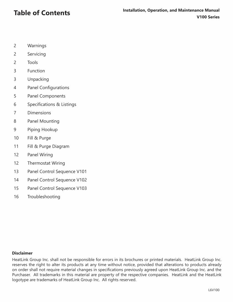
Table of ContentsV100 Series
Installation, Operation, and Maintenance Manual
2 Warnings
2 Servicing
2 Tools
3 Function
3 Unpacking
4 PanelConfigurations
5 Panel Components
6 Specifications&Listings
7 Dimensions
8 Panel Mounting
9 Piping Hookup
10 Fill&Purge
11 Fill&PurgeDiagram
12 Panel Wiring
12 Thermostat Wiring
13 Panel Control Sequence V101
14 Panel Control Sequence V102
15 Panel Control Sequence V103
16 Troubleshooting
Disclaimer
Thezonecontrolpanelisforindooruseonlyandmustbeinstalledbyaqualifiedinstaller/servicetechnician.This product must be installed and operated in strict accordance with the terms set out in this manual and in accordance with the relevant requirements of the Local Authority Having Jurisdiction. Failure to comply will result in a void of warranty, and may also result in property damage, serious injury, or death.
Prior to commencing installation of this panel it is necessary to read and understand all sections of this manual. The symbols below are used throughout this document to ensure proper operation of the panel, and your safety. Please pay attention to these symbols.
Inordertoavoidinjuryordeath,switchoffthepowertothepanelpriortoinspecting or making connections to the terminal strip.
WarningPossible Hazard
WarningLive Power
WarningHot Pipes
WarningTreated Water
®
Heat Linkwww.heatlink.com
2
V100 SeriesInstallation, Operation, and Maintenance Manual
L6V100
• Level
• Screwdriver or power drill
• Flat head bit
• Phillips head bit # 2
• 2 adjustable wrenches (or 2 × 30mm wrenches)
Warnings
Servicing
Tools
This zone control panel can provide mixing, distribution, and zoning for a wide variety of hydronic heating applications.Theeffectivenessofthesystemisdependantonthesystembeingdesignedandinstalledcorrectly.Properconsideration of factors such as BTU loads, outdoor design temperature, indoor design temperature, room set-pointtemperature(s),differentialfluidtemperatures,headloss,flowrates,andtransfercapacitiesoftheheatemitters is critical.Once these factors have been considered and the system requirements determined, these can then be evaluated and compared to the panel capabilities.
®Heat Link
3
®
Heat Linkwww.heatlink.com
V100 SeriesInstallation, Operation, and Maintenance Manual
L6V100
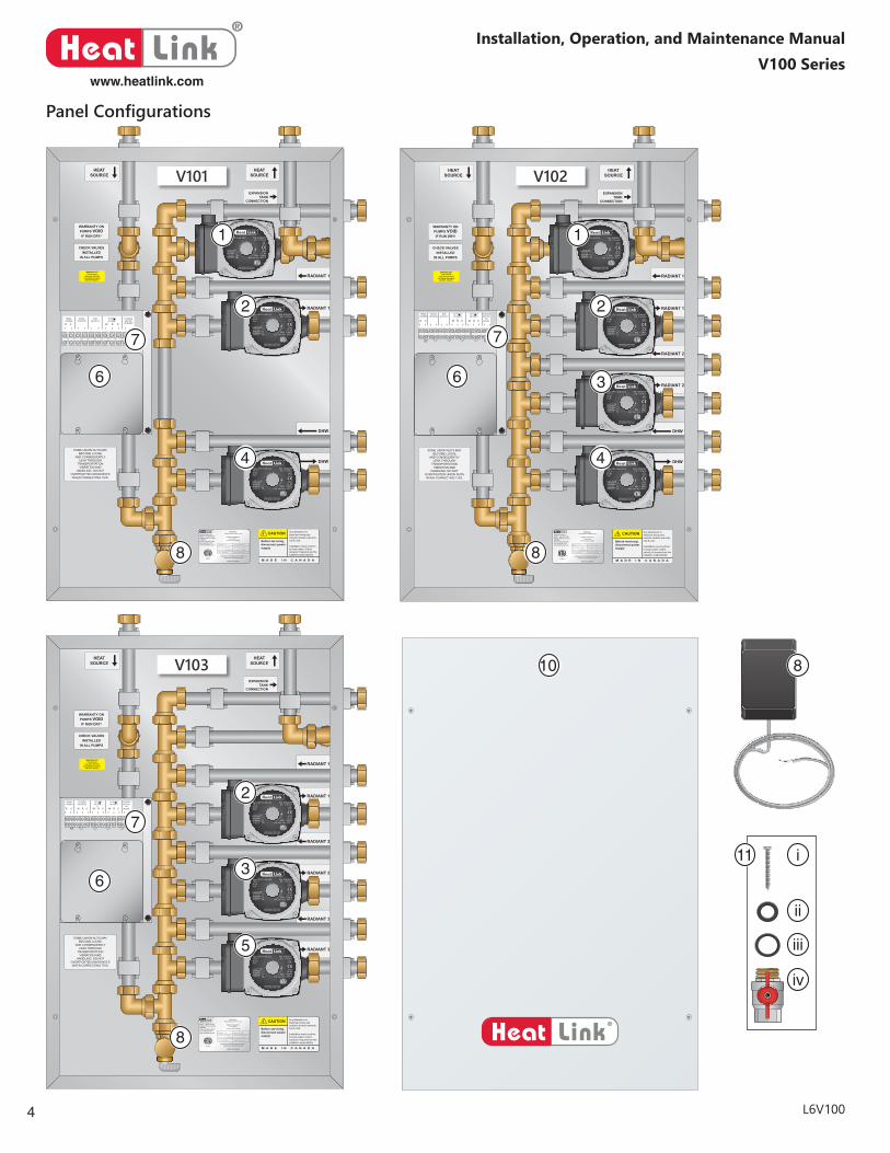
Note: The V101 and V101 boiler panels are designed to work with the Vitodens 100-W B1HA-26 or B1HA-35 boiler, and feature a primary pump. The V103 boiler panel is designed to work with the Vitodens 100-W BIKA-35 boiler, which has a built-in primary pump, and Domestic Hot Water priority diverting valve. The panel features only three radiant pumps.
Step 1 Examine carton for any damage that may have occurred during shipping. If damage is visible notify your courier and supplier immediately.
Step 2 Open the carton by removing the staples.
Step 3 Remove the cardboard spacers from the carton, then remove the panel from the carton. Lift the panel by the base, not the enclosure.
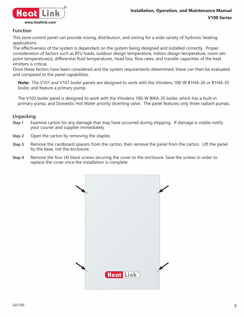
Step 4 Remove the four (4) black screws securing the cover to the enclosure. Save the screws in order to replace the cover once the installation is complete.
Function
Unpacking
®
Heat Linkwww.heatlink.com
4
V100 SeriesInstallation, Operation, and Maintenance Manual
L6V100
WARNING!!!Consult Manual Before Use
AVERTISSEMENT!!!Consulter le
manual avant l’usage
HeatLink Group Inc.4603E - 13th Street NECalgary, Alberta, CanadaT2E 6M3Phone: (403) 250-3432Fax: (403) 250-1155www.heatlinkgroup.com
Conforms to Std CAN/CSA C22.2 No. 14Conforms to Standard UL 508
MADE IN CANADA
MODEL #: V103
D.O.M: Feb. 27, 2015
Max Pres: 125psi/862kPa
Volts: 120/24 VAC
Serial #: XXX-XXXX
Phase/Freq: 1/60 Cycles
Max Temp: 100C/212F
Amps: Maximum 15
3189472
SOME UNION NUTS MAYBECOME LOOSE
AND CONSEQUENTLYLEAK THROUGH
TRANSPORTATIONVIBRATION AND
HANDLING. DO NOTOVERTIGHTEN UNION NUTSWHEN CORRECTING THIS.
CHECK VALVESINSTALLED
IN ALL PUMPS
WARRANTY ONPUMPS VOIDIF RUN DRY!
Any alterations to electrical wiring andcontrols renders warrantynull & void.
Installation must conformto local codes. Check valve(s) if required are theinstallers responsibility.
Before servicing,disconnect powersupply
M A D E I N C A N A D A
CAUTION
HEATSOURCE
EXPANSIONTANK
CONNECTION
HEATSOURCE
RADIANT 1
RADIANT 1
RADIANT 2
RADIANT 2
RADIANT 3
RADIANT 3
WARNING HOTThis product
may have hot fluidcirculating through it.
DO NOT TOUCH !
Type UPS 15-58 CIL2115 V ~60 Hz8 μF
P/N: 97948357 PC: 1131HLK
IP42TF 95
Max. 1.0MPaMax. water temp. 203°F
FR
IMPEDANCE PROTECTEDFOR INDOOR USE ONLY
|1/1(A) P1 (W)0.510.590.64
566773
Type UPS 15-58 CIL2115 V ~60 Hz8 μF
P/N: 97948357 PC: 1131HLK
IP42TF 95
Max. 1.0MPaMax. water temp. 203°F
FR
IMPEDANCE PROTECTEDFOR INDOOR USE ONLY
|1/1(A) P1 (W)0.510.590.64
566773
Type UPS 15-58 CIL2115 V ~60 Hz8 μF
P/N: 97948357 PC: 1131HLK
IP42TF 95
Max. 1.0MPaMax. water temp. 203°F
FR
IMPEDANCE PROTECTEDFOR INDOOR USE ONLY
|1/1(A) P1 (W)0.510.590.64
566773
WARNING!!!Consult Manual Before Use
AVERTISSEMENT!!!Consulter le
manual avant l’usage
HeatLink Group Inc.4603E - 13th Street NECalgary, Alberta, CanadaT2E 6M3Phone: (403) 250-3432Fax: (403) 250-1155www.heatlinkgroup.com
Conforms to Std CAN/CSA C22.2 No. 14Conforms to Standard UL 508
MADE IN CANADA
MODEL #: V102
D.O.M: Feb. 27, 2015
Max Pres: 125psi/862kPa
Volts: 120/24 VAC
Serial #: XXX-XXXX
Phase/Freq: 1/60 Cycles
Max Temp: 100C/212F
Amps: Maximum 15
3189472
SOME UNION NUTS MAYBECOME LOOSE
AND CONSEQUENTLYLEAK THROUGH
TRANSPORTATIONVIBRATION AND
HANDLING. DO NOTOVERTIGHTEN UNION NUTSWHEN CORRECTING THIS.
CHECK VALVESINSTALLED
IN ALL PUMPS
WARRANTY ONPUMPS VOIDIF RUN DRY!
Any alterations to electrical wiring andcontrols renders warrantynull & void.
Installation must conformto local codes. Check valve(s) if required are theinstallers responsibility.
Before servicing,disconnect powersupply
M A D E I N C A N A D A
CAUTION
HEATSOURCE
EXPANSIONTANK
CONNECTION
HEATSOURCE
RADIANT 1
RADIANT 1
RADIANT 2
RADIANT 2
DHW
DHW
WARNING HOTThis product
may have hot fluidcirculating through it.
DO NOT TOUCH !
Type UPS 15-58 CIL2115 V ~60 Hz8 μF
P/N: 97948357 PC: 1131HLK
IP42TF 95
Max. 1.0MPaMax. water temp. 203°F
FR
IMPEDANCE PROTECTEDFOR INDOOR USE ONLY
|1/1(A) P1 (W)0.510.590.64
566773
Type UPS 15-58 CIL2115 V ~60 Hz8 μF
P/N: 97948357 PC: 1131HLK
IP42TF 95
Max. 1.0MPaMax. water temp. 203°F
FR
IMPEDANCE PROTECTEDFOR INDOOR USE ONLY
|1/1(A) P1 (W)0.510.590.64
566773
Type UPS 15-58 CIL2115 V ~60 Hz8 μF
P/N: 97948357 PC: 1131HLK
IP42TF 95
Max. 1.0MPaMax. water temp. 203°F
FR
IMPEDANCE PROTECTEDFOR INDOOR USE ONLY
|1/1(A) P1 (W)0.510.590.64
566773
Type UPS 15-58 CIL2115 V ~60 Hz8 μF
P/N: 97948357 PC: 1131HLK
IP42TF 95
Max. 1.0MPaMax. water temp. 203°F
FR
IMPEDANCE PROTECTEDFOR INDOOR USE ONLY
|1/1(A) P1 (W)0.510.590.64
566773
®Heat Link
WARNING!!!Consult Manual Before Use
AVERTISSEMENT!!!Consulter le
manual avant l’usage
HeatLink Group Inc.4603E - 13th Street NECalgary, Alberta, CanadaT2E 6M3Phone: (403) 250-3432Fax: (403) 250-1155www.heatlinkgroup.com
Conforms to Std CAN/CSA C22.2 No. 14Conforms to Standard UL 508
MADE IN CANADA
MODEL #: V101
D.O.M: Feb. 27, 2015
Max Pres: 125psi/862kPa
Volts: 120/24 VAC
Serial #: XXX-XXXX
Phase/Freq: 1/60 Cycles
Max Temp: 100C/212F
Amps: Maximum 15
3189472
SOME UNION NUTS MAYBECOME LOOSE
AND CONSEQUENTLYLEAK THROUGH
TRANSPORTATIONVIBRATION AND
HANDLING. DO NOTOVERTIGHTEN UNION NUTSWHEN CORRECTING THIS.
CHECK VALVESINSTALLED
IN ALL PUMPS
WARRANTY ONPUMPS VOIDIF RUN DRY!
Any alterations to electrical wiring andcontrols renders warrantynull & void.
Installation must conformto local codes. Check valve(s) if required are theinstallers responsibility.
Before servicing,disconnect powersupply
M A D E I N C A N A D A
CAUTION
HEATSOURCE
EXPANSIONTANK
CONNECTION
HEATSOURCE
RADIANT 1
RADIANT 1
DHW
DHW
WARNING HOTThis product
may have hot fluidcirculating through it.
DO NOT TOUCH !
Type UPS 15-58 CIL2115 V ~60 Hz8 μF
P/N: 97948357 PC: 1131HLK
IP42TF 95
Max. 1.0MPaMax. water temp. 203°F
FR
IMPEDANCE PROTECTEDFOR INDOOR USE ONLY
|1/1(A) P1 (W)0.510.590.64
566773
Type UPS 15-58 CIL2115 V ~60 Hz8 μF
P/N: 97948357 PC: 1131HLK
IP42TF 95
Max. 1.0MPaMax. water temp. 203°F
FR
IMPEDANCE PROTECTEDFOR INDOOR USE ONLY
|1/1(A) P1 (W)0.510.590.64
566773
Type UPS 15-58 CIL2115 V ~60 Hz8 μF
P/N: 97948357 PC: 1131HLK
IP42TF 95
Max. 1.0MPaMax. water temp. 203°F
FR
IMPEDANCE PROTECTEDFOR INDOOR USE ONLY
|1/1(A) P1 (W)0.510.590.64
566773
1
2 2
2
3
3
44
5
6
6 6
7
8
8 8
7 7
1
V102V101
V103 8
i
ii
iii
iv
10
11
Panel Configurations
5
®
Heat Linkwww.heatlink.com
V100 SeriesInstallation, Operation, and Maintenance Manual
L6V100
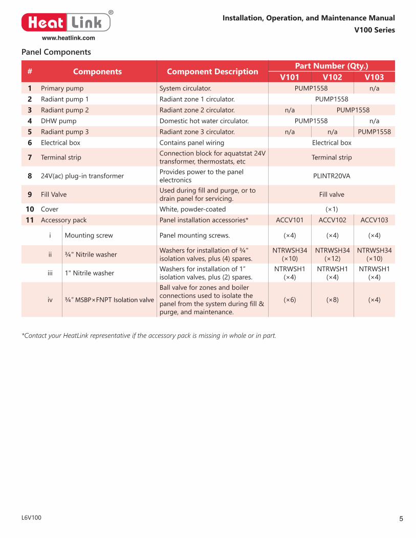
# Components Component Description Part Number (Qty.)V101 V102 V103
1 Primary pump System circulator. PUMP1558 n/a2 Radiant pump 1 Radiant zone 1 circulator. PUMP15583 Radiant pump 2 Radiant zone 2 circulator. n/a PUMP15584 DHW pump Domestic hot water circulator. PUMP1558 n/a5 Radiant pump 3 Radiant zone 3 circulator. n/a n/a PUMP15586 Electrical box Contains panel wiring Electrical box
7 Terminal strip Connection block for aquatstat 24V transformer, thermostats, etc Terminal strip
8 24V(ac) plug-in transformer Provides power to the panel electronics PLINTR20VA
9 Fill Valve Usedduringfillandpurge,ortodrain panel for servicing. Fill valve
10 Cover White, powder-coated (×1)11 Accessory pack Panel installation accessories* ACCV101 ACCV102 ACCV103
i Mounting screw Panel mounting screws. (×4) (×4) (×4)
ii ¾" Nitrile washer Washers for installation of ¾" isolation valves, plus (4) spares.
NTRWSH34 (×10)
NTRWSH34 (×12)
NTRWSH34 (×10)
iii 1" Nitrile washer Washers for installation of 1” isolation valves, plus (2) spares.
NTRWSH1 (×4)
NTRWSH1 (×4)
NTRWSH1 (×4)
iv ¾” MSBP×FNPT Isolation valve
Ball valve for zones and boiler connections used to isolate the panelfromthesystemduringfill&purge, and maintenance.
(×6) (×8) (×4)
*Contact your HeatLink representative if the accessory pack is missing in whole or in part.
Panel Components
®
Heat Linkwww.heatlink.com
6
V100 SeriesInstallation, Operation, and Maintenance Manual
L6V100
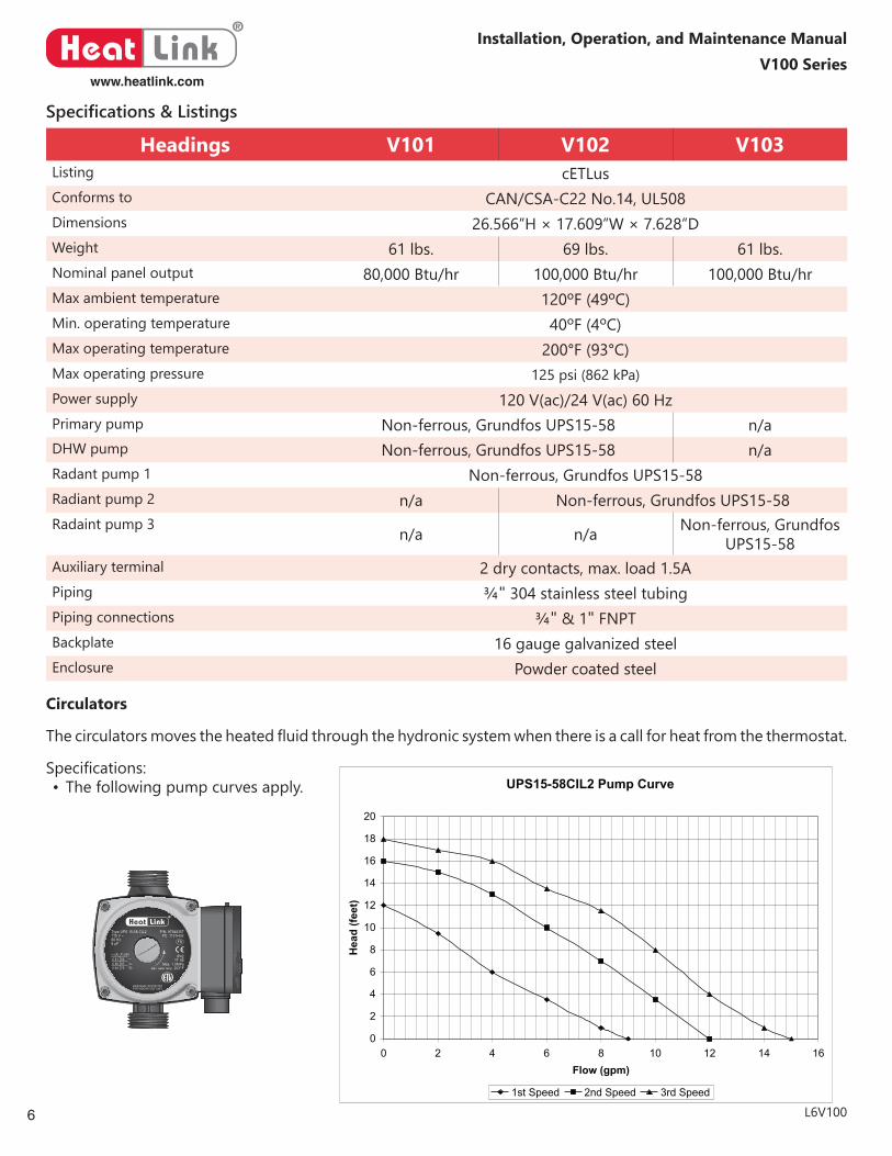
Headings V101 V102 V103Listing cETLusConforms to CAN/CSA-C22No.14,UL508Dimensions 26.566”H × 17.609”W × 7.628”DWeight 61 lbs. 69 lbs. 61 lbs.Nominal panel output 80,000Btu/hr 100,000Btu/hr 100,000Btu/hrMax ambient temperature 120ºF (49ºC)Min. operating temperature 40ºF (4ºC)Max operating temperature 200°F (93°C)Max operating pressure 125 psi (862 kPa)Power supply 120V(ac)/24V(ac)60HzPrimary pump Non-ferrous, Grundfos UPS15-58 n/aDHW pump Non-ferrous, Grundfos UPS15-58 n/aRadant pump 1 Non-ferrous, Grundfos UPS15-58Radiant pump 2 n/a Non-ferrous, Grundfos UPS15-58Radaint pump 3 n/a n/a Non-ferrous, Grundfos
UPS15-58Auxiliary terminal 2 dry contacts, max. load 1.5APiping ¾"304stainlesssteeltubingPiping connections ¾"&1"FNPTBackplate 16 gauge galvanized steelEnclosure Powder coated steel
Specifications & Listings
Circulators
Thecirculatorsmovestheheatedfluidthroughthehydronicsystemwhenthereisacallforheatfromthethermostat.
Specifications:• The following pump curves apply.
Type UPS 15-58 CIL2115 V ~60 Hz8 μF
P/N: 97948357 PC: 1131HLK
IP42TF 95
Max. 1.0MPaMax. water temp. 203°F
FR
IMPEDANCE PROTECTEDFOR INDOOR USE ONLY
|1/1(A) P1 (W)0.510.590.64
566773
UPS15-58CIL2 Pump Curve
0
2
4
6
8
10
12
14
16
18
20
0 2 4 6 8 10 12 14 16Flow (gpm)
Hea
d (fe
et)
1st Speed 2nd Speed 3rd Speed
7
®
Heat Linkwww.heatlink.com
V100 SeriesInstallation, Operation, and Maintenance Manual
L6V100
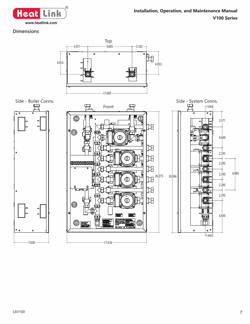
Dimensions
17.418
26.375 26.566
1.643
6.930
2.295
2.295
2.295
2.295
2.295
4.600
3.371
1.643
7.628
17.609
4.953
4.551 9.685 3.182
4.953
6.885
Top
FrontSide - Boiler Conns. Side - System Conns.
®
Heat Linkwww.heatlink.com
8
V100 SeriesInstallation, Operation, and Maintenance Manual
L6V100
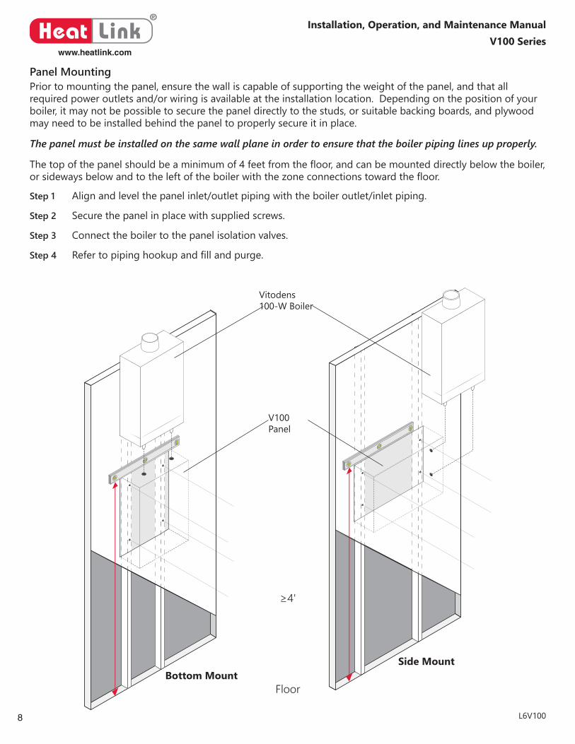
Prior to mounting the panel, ensure the wall is capable of supporting the weight of the panel, and that all requiredpoweroutletsand/orwiringisavailableattheinstallationlocation.Dependingonthepositionofyourboiler, it may not be possible to secure the panel directly to the studs, or suitable backing boards, and plywood may need to be installed behind the panel to properly secure it in place.
The panel must be installed on the same wall plane in order to ensure that the boiler piping lines up properly.
Thetopofthepanelshouldbeaminimumof4feetfromthefloor,andcanbemounteddirectlybelowtheboiler,orsidewaysbelowandtotheleftoftheboilerwiththezoneconnectionstowardthefloor.
Step 1 Alignandlevelthepanelinlet/outletpipingwiththeboileroutlet/inletpiping.
Step 2 Secure the panel in place with supplied screws.
Step 3 Connect the boiler to the panel isolation valves.
Step 4 Refertopipinghookupandfillandpurge.
Vitodens100-W Boiler
V100 Panel
Bottom MountSide Mount
Floor
≥4'
Panel Mounting
9
®
Heat Linkwww.heatlink.com
V100 SeriesInstallation, Operation, and Maintenance Manual
L6V100
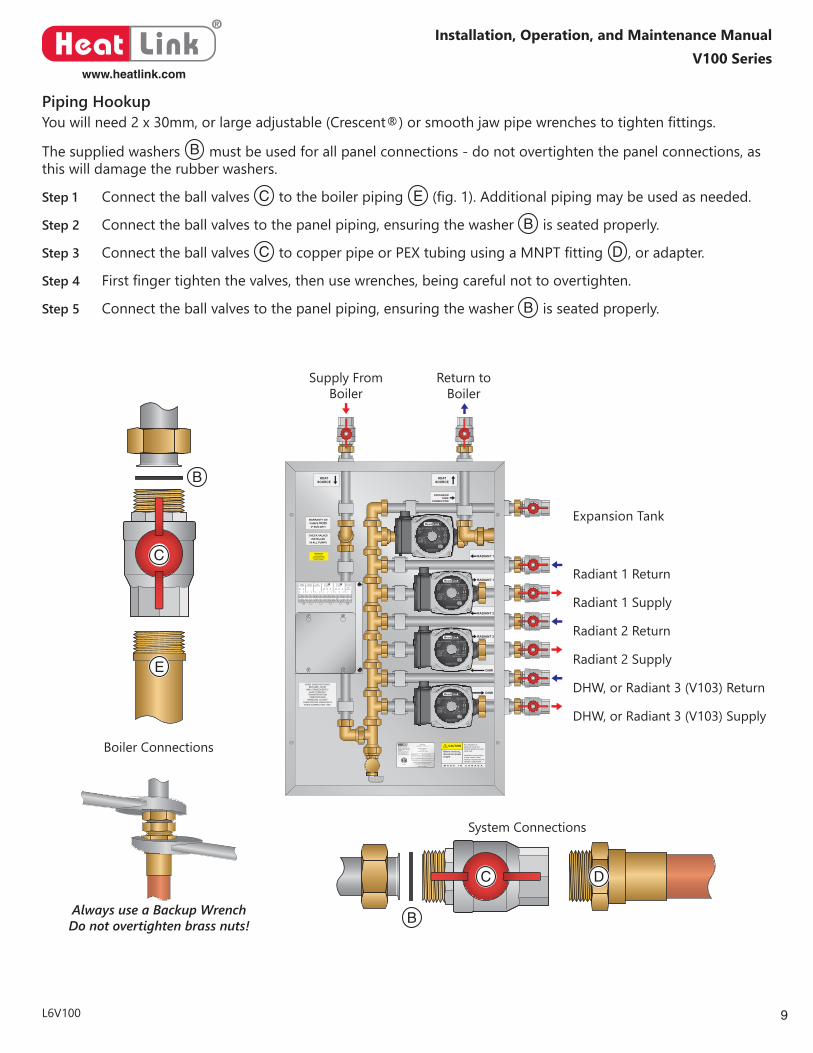
Youwillneed2x30mm,orlargeadjustable(Crescent®)orsmoothjawpipewrenchestotightenfittings.
The supplied washers B must be used for all panel connections - do not overtighten the panel connections, as this will damage the rubber washers.
Step 1 Connect the ball valves C to the boiler piping E (fig.1).Additionalpipingmaybeusedasneeded.
Step 2 Connect the ball valves to the panel piping, ensuring the washer B is seated properly.
Step 3 Connect the ball valves C tocopperpipeorPEXtubingusingaMNPTfitting D , or adapter.
Step 4 Firstfingertightenthevalves,thenusewrenches,beingcarefulnottoovertighten.
Step 5 Connect the ball valves to the panel piping, ensuring the washer B is seated properly.
WARNING!!!Consult Manual Before Use
AVERTISSEMENT!!!Consulter le
manual avant l’usage
HeatLink Group Inc.4603E - 13th Street NECalgary, Alberta, CanadaT2E 6M3Phone: (403) 250-3432Fax: (403) 250-1155www.heatlinkgroup.com
Conforms to Std CAN/CSA C22.2 No. 14Conforms to Standard UL 508
MADE IN CANADA
MODEL #: V102
D.O.M: Feb. 27, 2015
Max Pres: 125psi/862kPa
Volts: 120/24 VAC
Serial #: XXX-XXXX
Phase/Freq: 1/60 Cycles
Max Temp: 100C/212F
Amps: Maximum 15
3189472
SOME UNION NUTS MAYBECOME LOOSE
AND CONSEQUENTLYLEAK THROUGH
TRANSPORTATIONVIBRATION AND
HANDLING. DO NOTOVERTIGHTEN UNION NUTSWHEN CORRECTING THIS.
CHECK VALVESINSTALLED
IN ALL PUMPS
WARRANTY ONPUMPS VOIDIF RUN DRY!
Any alterations to electrical wiring andcontrols renders warrantynull & void.
Installation must conformto local codes. Check valve(s) if required are theinstallers responsibility.
Before servicing,disconnect powersupply
M A D E I N C A N A D A
CAUTION
HEATSOURCE
EXPANSIONTANK
CONNECTION
HEATSOURCE
RADIANT 1
RADIANT 1
RADIANT 2
RADIANT 2
DHW
DHW
WARNING HOTThis product
may have hot fluidcirculating through it.
DO NOT TOUCH !
Type UPS 15-58 CIL2115 V ~60 Hz8 μF
P/N: 97948357 PC: 1131HLK
IP42TF 95
Max. 1.0MPaMax. water temp. 203°F
FR
IMPEDANCE PROTECTEDFOR INDOOR USE ONLY
|1/1(A) P1 (W)0.510.590.64
566773
Type UPS 15-58 CIL2115 V ~60 Hz8 μF
P/N: 97948357 PC: 1131HLK
IP42TF 95
Max. 1.0MPaMax. water temp. 203°F
FR
IMPEDANCE PROTECTEDFOR INDOOR USE ONLY
|1/1(A) P1 (W)0.510.590.64
566773
Type UPS 15-58 CIL2115 V ~60 Hz8 μF
P/N: 97948357 PC: 1131HLK
IP42TF 95
Max. 1.0MPaMax. water temp. 203°F
FR
IMPEDANCE PROTECTEDFOR INDOOR USE ONLY
|1/1(A) P1 (W)0.510.590.64
566773
Type UPS 15-58 CIL2115 V ~60 Hz8 μF
P/N: 97948357 PC: 1131HLK
IP42TF 95
Max. 1.0MPaMax. water temp. 203°F
FR
IMPEDANCE PROTECTEDFOR INDOOR USE ONLY
|1/1(A) P1 (W)0.510.590.64
566773
Expansion Tank
Radiant 1 Return
Radiant 1 Supply
Radiant 2 Return
Radiant 2 Supply
DHW, or Radiant 3 (V103) Return
DHW, or Radiant 3 (V103) Supply
Always use a Backup WrenchDo not overtighten brass nuts!
Boiler Connections
System Connections
B
B
C
C
D
E
Supply FromBoiler
Return to Boiler
Piping Hookup
®
Heat Linkwww.heatlink.com
10
V100 SeriesInstallation, Operation, and Maintenance Manual
L6V100
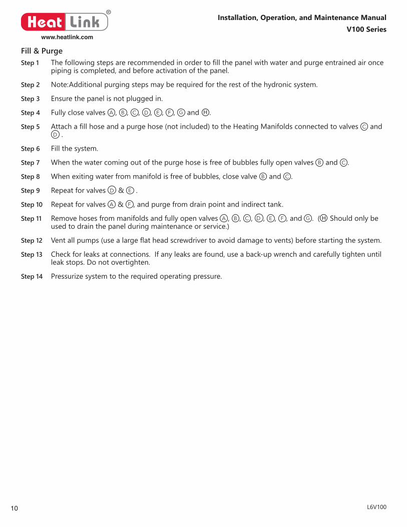
Step 1 Thefollowingstepsarerecommendedinordertofillthepanelwithwaterandpurgeentrainedaironcepiping is completed, and before activation of the panel.
Step 2 Note:Additionalpurgingstepsmayberequiredfortherestofthehydronicsystem.
Step 3 Ensure the panel is not plugged in.
Step 4 Fully close valves A , B , C , D , E , F , G and H .
Step 5 Attachafillhoseandapurgehose(notincluded)totheHeatingManifoldsconnectedtovalves C and D .
Step 6 Fill the system.
Step 7 When the water coming out of the purge hose is free of bubbles fully open valves B and C .
Step 8 When exiting water from manifold is free of bubbles, close valve B and C .
Step 9 Repeat for valves D & E .
Step 10 Repeat for valves A & F , and purge from drain point and indirect tank.
Step 11 Remove hoses from manifolds and fully open valves A , B , C , D , E , F , and G . ( H Should only be used to drain the panel during maintenance or service.)
Step 12 Ventallpumps(usealargeflatheadscrewdrivertoavoiddamagetovents)beforestartingthesystem.
Step 13 Check for leaks at connections. If any leaks are found, use a back-up wrench and carefully tighten until leak stops. Do not overtighten.
Step 14 Pressurize system to the required operating pressure.
Fill & Purge
11
®
Heat Linkwww.heatlink.com
V100 SeriesInstallation, Operation, and Maintenance Manual
L6V100
WARNING!!!Consult Manual Before Use
AVERTISSEMENT!!!Consulter le
manual avant l’usage
HeatLink Group Inc.4603E - 13th Street NECalgary, Alberta, CanadaT2E 6M3Phone: (403) 250-3432Fax: (403) 250-1155www.heatlinkgroup.com
Conforms to Std CAN/CSA C22.2 No. 14Conforms to Standard UL 508
MADE IN CANADA
MODEL #: V102
D.O.M: Feb. 27, 2015
Max Pres: 125psi/862kPa
Volts: 120/24 VAC
Serial #: XXX-XXXX
Phase/Freq: 1/60 Cycles
Max Temp: 100C/212F
Amps: Maximum 15
3189472
SOME UNION NUTS MAYBECOME LOOSE
AND CONSEQUENTLYLEAK THROUGH
TRANSPORTATIONVIBRATION AND
HANDLING. DO NOTOVERTIGHTEN UNION NUTSWHEN CORRECTING THIS.
CHECK VALVESINSTALLED
IN ALL PUMPS
WARRANTY ONPUMPS VOIDIF RUN DRY!
Any alterations to electrical wiring andcontrols renders warrantynull & void.
Installation must conformto local codes. Check valve(s) if required are theinstallers responsibility.
Before servicing,disconnect powersupply
M A D E I N C A N A D A
CAUTION
HEATSOURCE
EXPANSIONTANK
CONNECTION
HEATSOURCE
RADIANT 1
RADIANT 1
RADIANT 2
RADIANT 2
DHW
DHW
WARNING HOTThis product
may have hot fluidcirculating through it.
DO NOT TOUCH !
Type UPS 15-58 CIL2115 V ~60 Hz8 μF
P/N: 97948357 PC: 1131HLK
IP42TF 95
Max. 1.0MPaMax. water temp. 203°F
FR
IMPEDANCE PROTECTEDFOR INDOOR USE ONLY
|1/1(A) P1 (W)0.510.590.64
566773
Type UPS 15-58 CIL2115 V ~60 Hz8 μF
P/N: 97948357 PC: 1131HLK
IP42TF 95
Max. 1.0MPaMax. water temp. 203°F
FR
IMPEDANCE PROTECTEDFOR INDOOR USE ONLY
|1/1(A) P1 (W)0.510.590.64
566773
Type UPS 15-58 CIL2115 V ~60 Hz8 μF
P/N: 97948357 PC: 1131HLK
IP42TF 95
Max. 1.0MPaMax. water temp. 203°F
FR
IMPEDANCE PROTECTEDFOR INDOOR USE ONLY
|1/1(A) P1 (W)0.510.590.64
566773
Type UPS 15-58 CIL2115 V ~60 Hz8 μF
P/N: 97948357 PC: 1131HLK
IP42TF 95
Max. 1.0MPaMax. water temp. 203°F
FR
IMPEDANCE PROTECTEDFOR INDOOR USE ONLY
|1/1(A) P1 (W)0.510.590.64
566773
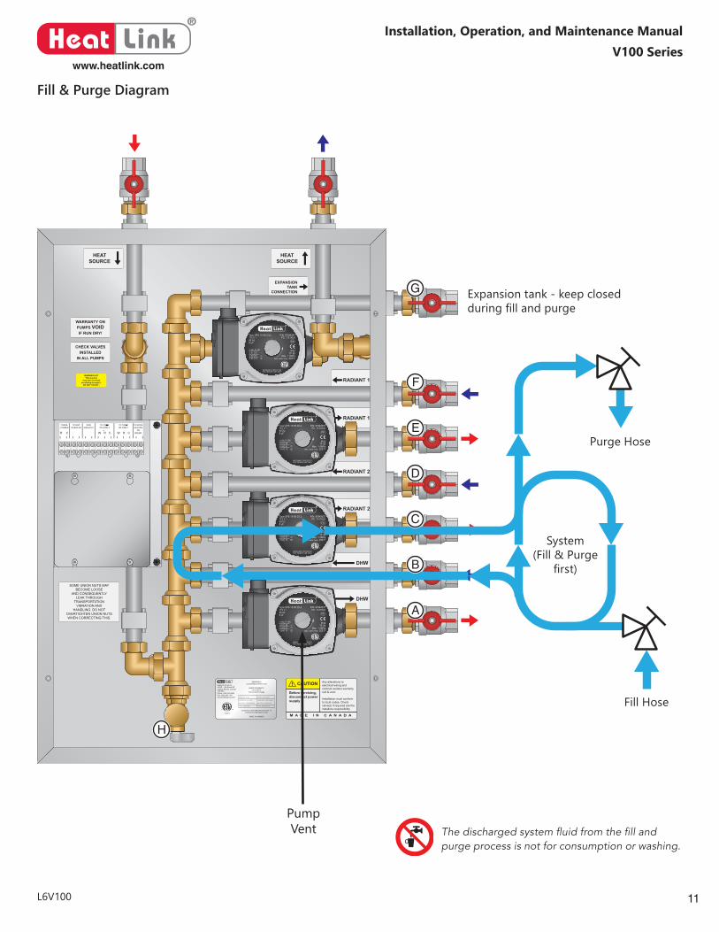
The discharged system fluid from the fill and purge process is not for consumption or washing.
A
B
C
D
E
F
G
H
Pump Vent
Fill Hose
Purge Hose
Expansion tank - keep closed duringfillandpurge
System(Fill&Purge
first)
Fill & Purge Diagram
®
Heat Linkwww.heatlink.com
12
V100 SeriesInstallation, Operation, and Maintenance Manual
L6V100
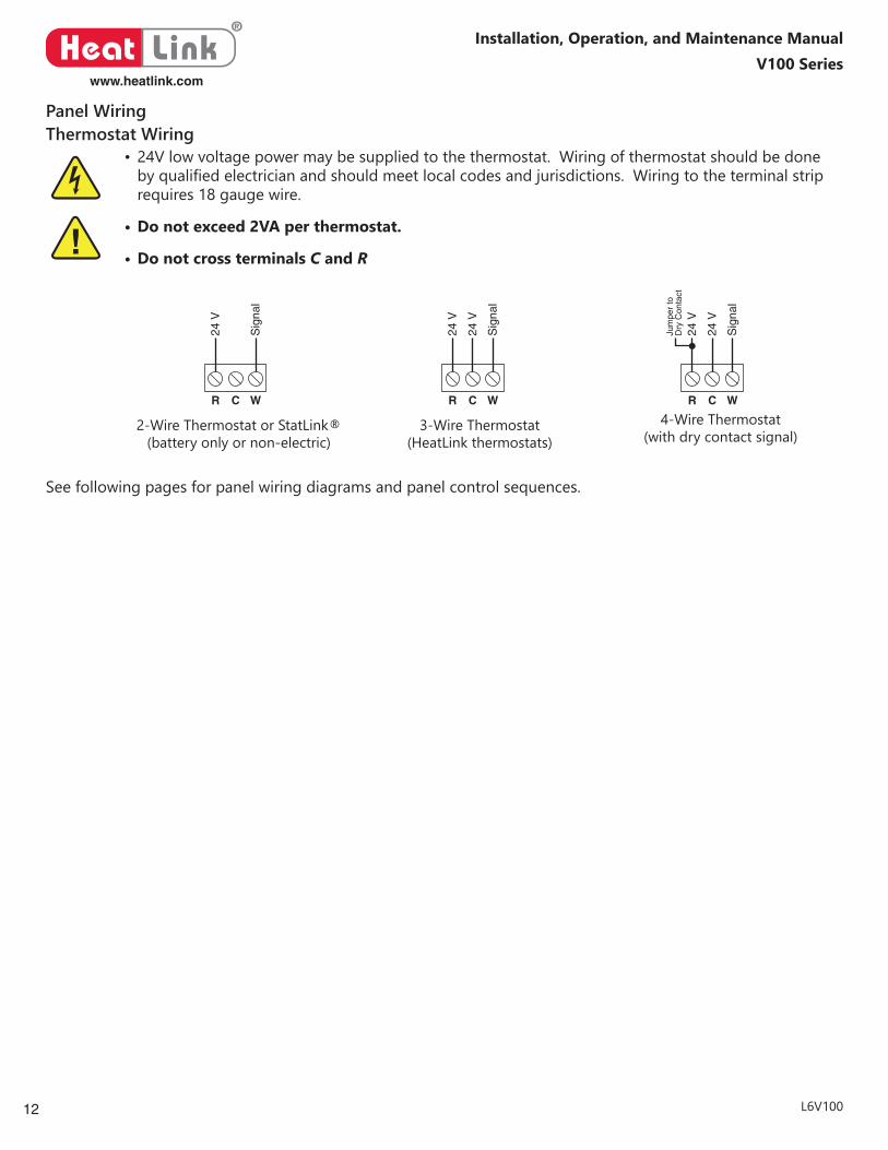
Panel WiringThermostat Wiring
• 24V low voltage power may be supplied to the thermostat. Wiring of thermostat should be done byqualifiedelectricianandshouldmeetlocalcodesandjurisdictions.Wiringtotheterminalstriprequires 18 gauge wire.
• Do not exceed 2VA per thermostat.
• Do not cross terminals C and R
WR C
24 V
Sig
nal
2-Wire Thermostat or StatLink®(battery only or non-electric)
WR C
24 V
24 V
Sig
nal
3-Wire Thermostat(HeatLink thermostats)
WR C
Sig
nal
24 V
24 V
Jum
per
to
Dry
Con
tact
4-Wire Thermostat(with dry contact signal)
See following pages for panel wiring diagrams and panel control sequences.
13
®
Heat Linkwww.heatlink.com
V100 SeriesInstallation, Operation, and Maintenance Manual
L6V100
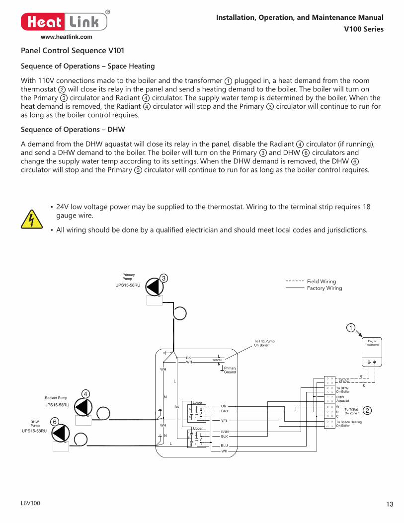
Panel Control Sequence V101
Sequence of Operations – Space Heating
With 110V connections made to the boiler and the transformer 1 plugged in, a heat demand from the room thermostat 2 will close its relay in the panel and send a heating demand to the boiler. The boiler will turn on the Primary 3 circulator and Radiant 4 circulator. The supply water temp is determined by the boiler. When the heat demand is removed, the Radiant 4 circulator will stop and the Primary 3 circulator will continue to run for as long as the boiler control requires.
Sequence of Operations – DHW
A demand from the DHW aquastat will close its relay in the panel, disable the Radiant 4 circulator (if running), and send a DHW demand to the boiler. The boiler will turn on the Primary 3 and DHW 6 circulators and change the supply water temp according to its settings. When the DHW demand is removed, the DHW 6 circulator will stop and the Primary 3 circulator will continue to run for as long as the boiler control requires.
1
2
3
4
6
• 24V low voltage power may be supplied to the thermostat. Wiring to the terminal strip requires 18 gauge wire.
• Allwiringshouldbedonebyaqualifiedelectricianandshouldmeetlocalcodesandjurisdictions.
Field WiringFactory Wiring
®
Heat Linkwww.heatlink.com
14
V100 SeriesInstallation, Operation, and Maintenance Manual
L6V100
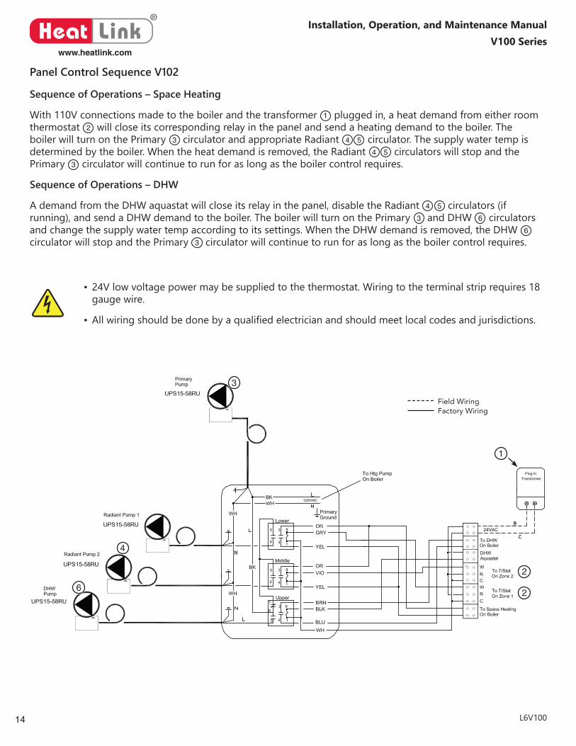
Panel Control Sequence V102
1
2
2
3
4
6
Sequence of Operations – Space Heating
With 110V connections made to the boiler and the transformer 1 plugged in, a heat demand from either room thermostat 2 will close its corresponding relay in the panel and send a heating demand to the boiler. The boiler will turn on the Primary 3 circulator and appropriate Radiant 4 5 circulator. The supply water temp is determined by the boiler. When the heat demand is removed, the Radiant 4 5 circulators will stop and the Primary 3 circulator will continue to run for as long as the boiler control requires.
Sequence of Operations – DHW
A demand from the DHW aquastat will close its relay in the panel, disable the Radiant 4 5 circulators (if running), and send a DHW demand to the boiler. The boiler will turn on the Primary 3 and DHW 6 circulators and change the supply water temp according to its settings. When the DHW demand is removed, the DHW 6 circulator will stop and the Primary 3 circulator will continue to run for as long as the boiler control requires.
• 24V low voltage power may be supplied to the thermostat. Wiring to the terminal strip requires 18 gauge wire.
• Allwiringshouldbedonebyaqualifiedelectricianandshouldmeetlocalcodesandjurisdictions.
Field WiringFactory Wiring
15
®
Heat Linkwww.heatlink.com
V100 SeriesInstallation, Operation, and Maintenance Manual
L6V100Part#Not to be handed over to, copied or used by third party.
Confidential: Property of ZCP Inc., Calgary, AB, Canada.
JOB/PROJECT:
CONTRACTOR:ENGIN./ARCH.
CLIENT/DISTRB ORDER No.:
CLIENT/DISTRB.:
TITLE:
ZONE CONTROL PANEL
Designed by Checked by Approved by:
1 of 1SheetEdition
1
ScaleDate
RevNo Revision note CheckedDate Signature
Heatlink can accept no responsibility for possible errors in printed matter and reserves the right to alter its products without notice.
ZONE CONTROL PANELElectrical LayoutNorth America, Heatlink Distribution Network
BW
VC.A01.A1.02
25.01.17
Electrical Schematic
Dwg #: Viessmann 103 + Combi
BW Viessmann 103 + Combi None
UPS15-58RU
Radiant Pump 1
UPS15-58RU
Radiant Pump 2
To T/Stat
To Space HeatingOn Boiler
On Zone 2
To T/StatOn Zone 1
TransformerPlug In
W
WCR
RC
To Htg PumpOn Boiler
24VACOR
OR
GRY
YEL
VIO
YEL
5
6
5
6
3
4
3
4
8
1
8
1
BKWH
BK
PrimaryGround
5
6
3
4
8
1
WH
FlowSwitch
Lower
Middle
Upper
BLK7
UPS15-58RU
Radiant Pump 3
5
6
3
4
8
1
Lower
To T/StatOn Zone 3
W
CR
OR
YEL
1
2
2
2
3
4
6
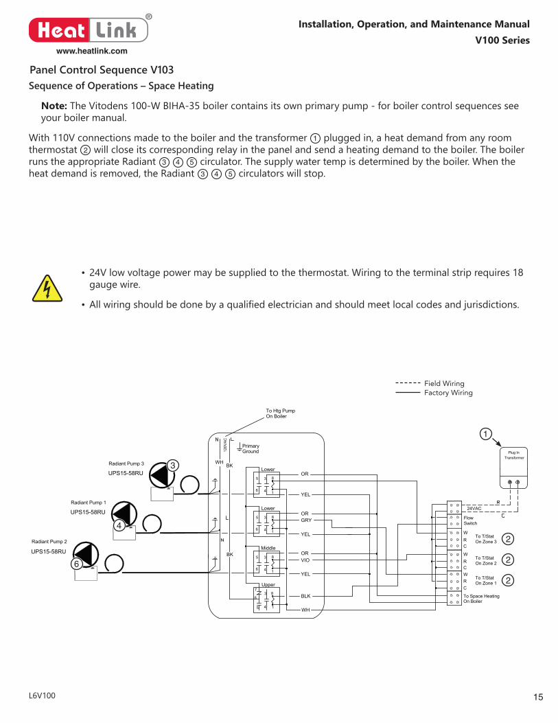
Sequence of Operations – Space Heating
Note: The Vitodens 100-W BIHA-35 boiler contains its own primary pump - for boiler control sequences see your boiler manual.
With 110V connections made to the boiler and the transformer 1 plugged in, a heat demand from any room thermostat 2 will close its corresponding relay in the panel and send a heating demand to the boiler. The boiler runs the appropriate Radiant 3 4 5 circulator. The supply water temp is determined by the boiler. When the heat demand is removed, the Radiant 3 4 5 circulators will stop.
• 24V low voltage power may be supplied to the thermostat. Wiring to the terminal strip requires 18 gauge wire.
• Allwiringshouldbedonebyaqualifiedelectricianandshouldmeetlocalcodesandjurisdictions.
Field WiringFactory Wiring
Panel Control Sequence V103
®
Heat Linkwww.heatlink.com
16
V100 SeriesInstallation, Operation, and Maintenance Manual
L6V100
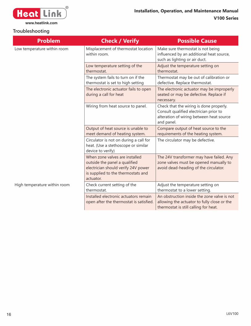
Troubleshooting
Problem Check / Verify Possible CauseLow temperature within room Misplacement of thermostat location
within room.Make sure thermostat is not being influencedbyanadditionalheatsource,such as lighting or air duct.
Low temperature setting of the thermostat.
Adjust the temperature setting on thermostat.
The system fails to turn on if the thermostat is set to high setting
Thermostat may be out of calibration or defective. Replace thermostat.
The electronic actuator fails to open during a call for heat
The electronic actuator may be improperly seated or may be defective. Replace if necessary.
Wiring from heat source to panel. Check that the wiring is done properly. Consultqualifiedelectricianpriortoalteration of wiring between heat source and panel.
Output of heat source is unable to meet demand of heating system.
Compare output of heat source to the requirements of the heating system.
Circulator is not on during a call for heat. (Use a stethoscope or similar device to verify)
The circulator may be defective.
When zone valves are installed outsidethepanelaqualifiedelectrician should verify 24V power is supplied to the thermostats and actuator.
The 24V transformer may have failed. Any zone valves must be opened manually to avoid dead-heading of the circulator.
High temperature within room Check current setting of the thermostat.
Adjust the temperature setting on thermostat to a lower setting.
Installed electronic actuators remain openafterthethermostatissatisfied.
An obstruction inside the zone valve is not allowing the actuator to fully close or the thermostat is still calling for heat.

®
Heat Linkwww.heatlink.com
Panel Line NameInstallation, Operation, and Maintenance Manual
©HeatLink Group Inc.Printed in CanadaAugust 16, 2017
CanadaManufactured & distributed by HeatLink Group Inc.Head Office:4603E - 13th Street N.E.Calgary, Alberta, T2E 6M3
Toll Free: 1-800-661-5332International Phone: +1 (403) 250-3432Fax: 1-866-450-1155
ChinaDistributed by Cathay-Links International Phone: 852-25693213Fax: 852-25359271
IrelandDistributed by Jamoni Ltd. Phone: 057 - 932 4062Fax: 057 - 932 4063Freephone: 1800-311338
MéxicoDistributed by Distribuidora Caisa S.A. de C.V.Phone: (52-55) 3300-4400Fax: (52-55) 3300-4406
United StatesDistributed by HeatLink Group Inc.USA Distribution Center:1000 - 100th Street SW, Suite BByron Center, MI, 49315
Toll Free: 1-800-661-5332Fax: 1-800-869-6098