Embed Size (px)
Citation preview

Edition 04.20EN
Pressure regulators with solenoid valve VAD, VAG, VAV Flow rate regulators VAH, VRH Pressure regulators with double solenoid valve VCD, VCG, VCV, VCH
• All-purpose servo regulator for gaseous media with integrated safety valve
• Suitable for a max. inlet pressure of 500 mbar (7 psig)• Minimum installation effort: no external impulse line required• Can be adjusted from two sides
03250530
TECHNICAL INFORMATION
AGA
Safety manual for products complying with EN 61508-2

VAD, VAG, VAH, VAV, VRH, VCD, VCG, VCV, VCH · Edition 04.20 · EN 2
ContentsContents . . . . . . . . . . . . . . . . . . . . . . . . . . . . . . . . . . . . . .21 Application . . . . . . . . . . . . . . . . . . . . . . . . . . . . . . . . . .41.1 Application examples . . . . . . . . . . . . . . . . . . . . . . . . . .61.1.1 Constant pressure control . . . . . . . . . . . . . . . . . . . . . . . . . 71.1.2 Constant pressure control with two gas solenoid valves . 71.1.3 Constant pressure control with max. pressure switch . . . 71.1.4 Constant pressure control with non-controlled pilot gas outlet . . . . . . . . . . . . . . . . . . . . . . . . . . . . . . . . . . . . . . . . . . . . . 71.1.5 Modulating control. . . . . . . . . . . . . . . . . . . . . . . . . . . . . . . 81.1.6 Modulating control with two gas solenoid valves . . . . . . . 81.1.7 Modulating control with two gas solenoid valves and inlet pressure switch . . . . . . . . . . . . . . . . . . . . . . . . . . . . . . . . . 91.1.8 High/Low control. . . . . . . . . . . . . . . . . . . . . . . . . . . . . . . . 91.1.9 Zero pressure control . . . . . . . . . . . . . . . . . . . . . . . . . . . . 91.1.10 Staged flow rate control. . . . . . . . . . . . . . . . . . . . . . . . . 101.1.11 Continuous or staged flow rate control . . . . . . . . . . . . . 101.1.12 Modulating control with variable air/gas ratio control with gas solenoid valve . . . . . . . . . . . . . . . . . . . . . . . . . . . . . . 111.1.13 Modulating control in residential heat generation. . . . . . 11
2 Certification . . . . . . . . . . . . . . . . . . . . . . . . . . . . . . . .123 Function . . . . . . . . . . . . . . . . . . . . . . . . . . . . . . . . . . . . 143.1 Pressure regulator for gas VAD . . . . . . . . . . . . . . . . . 143.2 Air/gas ratio control VAG . . . . . . . . . . . . . . . . . . . . . . 153.3 Flow rate regulators VAH, VRH . . . . . . . . . . . . . . . . . 153.4 Variable air/gas ratio control VAV . . . . . . . . . . . . . . . . 163.5 Pressure regulator with gas solenoid valve VAx..S and closed position indicator . . . . . . . . . . . . . . . . . . . . . 173.6 Connection diagram . . . . . . . . . . . . . . . . . . . . . . . . . 18
4 Flow rate . . . . . . . . . . . . . . . . . . . . . . . . . . . . . . . . . . .194.1 Calculating the nominal size. . . . . . . . . . . . . . . . . . . . 194.2 VAD . . . . . . . . . . . . . . . . . . . . . . . . . . . . . . . . . . . . . .204.3 VAG, VAH, VRH, VAV. . . . . . . . . . . . . . . . . . . . . . . . . 224.4 Zero governor VAG..N . . . . . . . . . . . . . . . . . . . . . . . . 244.4.1 Calculating the nominal size . . . . . . . . . . . . . . . . . . . . . . 25
5 Selection . . . . . . . . . . . . . . . . . . . . . . . . . . . . . . . . . . .265.1 ProFi . . . . . . . . . . . . . . . . . . . . . . . . . . . . . . . . . . . . .265.2 VAD selection table . . . . . . . . . . . . . . . . . . . . . . . . . . 275.3 VAG, VAH, VAV selection table . . . . . . . . . . . . . . . . . 285.4 VRH selection table. . . . . . . . . . . . . . . . . . . . . . . . . .295.5 Type code . . . . . . . . . . . . . . . . . . . . . . . . . . . . . . . . .305.6 Accessory selection . . . . . . . . . . . . . . . . . . . . . . . . . 31
6 Project planning information . . . . . . . . . . . . . . . . . .326.1 Test points . . . . . . . . . . . . . . . . . . . . . . . . . . . . . . . . . 326.2 Installation . . . . . . . . . . . . . . . . . . . . . . . . . . . . . . . . .336.2.1 Installation position . . . . . . . . . . . . . . . . . . . . . . . . . . . . . 34
6.3 Setting the low-fire rate on VAG, VAH, VRH, VAV . . . 346.4 Setting the high-fire rate on VAV . . . . . . . . . . . . . . . . 356.5 Electrical connection . . . . . . . . . . . . . . . . . . . . . . . . . 35
7 Accessories . . . . . . . . . . . . . . . . . . . . . . . . . . . . . . . . .367.1 Pressure switch for gas DG..C . . . . . . . . . . . . . . . . . .367.2 DG..C fastening set for VAx 1–3. . . . . . . . . . . . . . . . .367.3 Bypass/pilot gas valve VAS 1. . . . . . . . . . . . . . . . . . . 377.3.1 Flow rate, VAS 1 attached to VAx 1, VAx 2, VAx 3 . . . . . 377.3.2 Scope of delivery of VAS 1 for VAx 1, VAx 2, VAx 3 . . . . 38
7.4 Bypass/pilot gas valve VBY 8. . . . . . . . . . . . . . . . . . .397.4.1 Flow rate, VBY. . . . . . . . . . . . . . . . . . . . . . . . . . . . . . . . . 397.4.2 Technical data VBY 8 . . . . . . . . . . . . . . . . . . . . . . . . . . . 407.4.3 Scope of delivery of VBY for VAx 1 . . . . . . . . . . . . . . . . . 407.4.4 Type code . . . . . . . . . . . . . . . . . . . . . . . . . . . . . . . . . . . . 40
7.5 Pressure test nipples . . . . . . . . . . . . . . . . . . . . . . . . . 417.6 Cable gland set . . . . . . . . . . . . . . . . . . . . . . . . . . . . . 417.7 Attachment block VA 1–3. . . . . . . . . . . . . . . . . . . . . . 417.8 Seal set for sizes 1–3 . . . . . . . . . . . . . . . . . . . . . . . . . 427.9 Differential pressure orifice . . . . . . . . . . . . . . . . . . . . . 427.10 Measuring orifice VMO . . . . . . . . . . . . . . . . . . . . . . .437.11 Filter module VMF. . . . . . . . . . . . . . . . . . . . . . . . . . .437.12 Fine-adjusting valve VMV . . . . . . . . . . . . . . . . . . . . .43

VAD, VAG, VAH, VAV, VRH, VCD, VCG, VCV, VCH · Edition 04.20 · EN 3
7.13 Gas control line. . . . . . . . . . . . . . . . . . . . . . . . . . . . .438 Technical data . . . . . . . . . . . . . . . . . . . . . . . . . . . . . .448.1 Ambient conditions . . . . . . . . . . . . . . . . . . . . . . . . . . 448.2 Mechanical data . . . . . . . . . . . . . . . . . . . . . . . . . . . . 448.3 Electrical data . . . . . . . . . . . . . . . . . . . . . . . . . . . . . . 45
9 Dimensions . . . . . . . . . . . . . . . . . . . . . . . . . . . . . . . . . 479.1 Rp internal thread, ISO flange . . . . . . . . . . . . . . . . . . 479.2 NPT internal thread, ANSI flange. . . . . . . . . . . . . . . .48
10 Converting units . . . . . . . . . . . . . . . . . . . . . . . . . . . .4911 Safety-specific characteristic values for SIL and PL . . . . . . . . . . . . . . . . . . . . . . . . . . . . . . . . . . . . . . .5011.1 Determining the PFHD value, λD value and MTTFd value . . . . . . . . . . . . . . . . . . . . . . . . . . . . . . . . . . . . . . . .5011.2 Designed lifetime . . . . . . . . . . . . . . . . . . . . . . . . . . . 5111.3 Use in safety-related systems. . . . . . . . . . . . . . . . . . 51
12 Safety information in accordance with EN 61508-2 . . . . . . . . . . . . . . . . . . . . . . . . . . . . . . . . . . .5212.1 Scope of application. . . . . . . . . . . . . . . . . . . . . . . . . 5212.2 Product description . . . . . . . . . . . . . . . . . . . . . . . . . 5212.3 Reference documents . . . . . . . . . . . . . . . . . . . . . . . 5212.4 Applicable standards . . . . . . . . . . . . . . . . . . . . . . . . 5212.5 Safety function . . . . . . . . . . . . . . . . . . . . . . . . . . . . . 5212.6 Safety instructions concerning operating limits . . . . 5212.7 Installation and commissioning . . . . . . . . . . . . . . . . 5212.8 Maintenance/Checks . . . . . . . . . . . . . . . . . . . . . . . . 5212.9 Troubleshooting . . . . . . . . . . . . . . . . . . . . . . . . . . . . 5212.10 Safety instructions concerning design verification . 5212.11 Characteristic safety data/SIL capability . . . . . . . . .5312.12 Mode of operation . . . . . . . . . . . . . . . . . . . . . . . . .53
13 Maintenance cycles . . . . . . . . . . . . . . . . . . . . . . . . .54
14 Glossary . . . . . . . . . . . . . . . . . . . . . . . . . . . . . . . . . . .5514.1 Diagnostic coverage DC. . . . . . . . . . . . . . . . . . . . . . 5514.2 Mode of operation . . . . . . . . . . . . . . . . . . . . . . . . . . 5514.3 Category . . . . . . . . . . . . . . . . . . . . . . . . . . . . . . . . . 5514.4 Common cause failure CCF. . . . . . . . . . . . . . . . . . . 5514.5 Fraction of undetected common cause failures β . . 5514.6 B10d value . . . . . . . . . . . . . . . . . . . . . . . . . . . . . . . . 5514.7 T10d value . . . . . . . . . . . . . . . . . . . . . . . . . . . . . . . . 5514.8 Hardware fault tolerance HFT . . . . . . . . . . . . . . . . . 5514.9 Mean dangerous failure rate λD . . . . . . . . . . . . . . . . 5514.10 Safe failure fraction SFF . . . . . . . . . . . . . . . . . . . . .5614.11 Probability of dangerous failure PFHD . . . . . . . . . .5614.12 Mean time to dangerous failure MTTFd . . . . . . . . .5614.13 Demand rate nop . . . . . . . . . . . . . . . . . . . . . . . . . .5614.14 Average probability of dangerous failure on demand PFDavg . . . . . . . . . . . . . . . . . . . . . . . . . . . . . . .56
For more information . . . . . . . . . . . . . . . . . . . . . . . . . . 57

VAD, VAG, VAH, VAV, VRH, VCD, VCG, VCV, VCH · Edition 04.20 · EN 4
Application
1 ApplicationRegulators with solenoid valves are designed for shut-off, and thanks to the servo technology, for precise control of the gas supply to gas burners and gas appliances. They are used in gas control and safety systems in all sectors of the iron, steel, glass and ceramics industries, as well as in residential or commercial heat generation, such as the packaging, paper and foodstuffs industries.
VAD
VAD
Constant pressure governor, Class A, with high control accuracy, for excess air burners, atmospheric burners or single-stage force draught burners. The pressure is preset via the setpoint spring. In the case of fluctuating furnace or kiln pressures, the furnace chamber pressure may also be connected for maintaining a constant burner capacity.
VAG
VAG
Air/gas ratio control, Class A, for maintaining a constant air/gas pressure ratio for modulating-controlled burners or with VAS 1 bypass valve for stage-controlled burners. The pres-sure is preset by the air control line. The VAG..N can also be used as a zero governor for gas engines.
VAD, VAG, VAH, VAV, VRH, VCD, VCG, VCV, VCH · Edition 04.20 · EN 5
Application
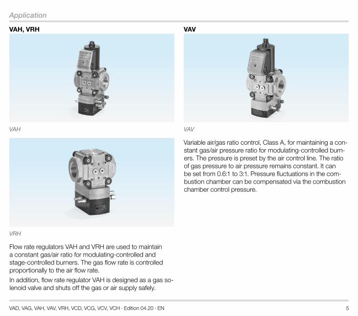
VAH, VRH
VAH
VRH
Flow rate regulators VAH and VRH are used to maintain a constant gas/air ratio for modulating-controlled and stage-controlled burners. The gas flow rate is controlled proportionally to the air flow rate.
In addition, flow rate regulator VAH is designed as a gas so-lenoid valve and shuts off the gas or air supply safely.
VAV
VAV
Variable air/gas ratio control, Class A, for maintaining a con-stant gas/air pressure ratio for modulating-controlled burn-ers. The pressure is preset by the air control line. The ratio of gas pressure to air pressure remains constant. It can be set from 0.6:1 to 3:1. Pressure fluctuations in the com-bustion chamber can be compensated via the combustion chamber control pressure.

VAD, VAG, VAH, VAV, VRH, VCD, VCG, VCV, VCH · Edition 04.20 · EN 6
Application
1 .1 Application examples
Pressure regulator on excess air burners in the ceramics indus-try
Air/gas ratio control on melting furnace for ensuring stoichio-metric combustion over the entire capacity range
Aluminium age-hardening furnace with air/gas ratio controls for low air pressure protection

VAD, VAG, VAH, VAV, VRH, VCD, VCG, VCV, VCH · Edition 04.20 · EN 7
Application
1 .1 .1 Constant pressure control
VAD
The pressure regulator with gas solenoid valve VAD main-tains the set gas outlet pressure pd constant when subject to differing flow rates. If a second gas solenoid valve is used upstream of the VAD, this complies with the requirements of EN 746-2 for two Class A gas solenoid valves connected in series.
1 .1 .2 Constant pressure control with two gas solenoid valves
VADVAS
The pressure regulator with gas solenoid valve VAD main-tains the set gas outlet pressure pd constant when subject to differing flow rates.
1 .1 .3 Constant pressure control with max . pressure switch
VAD
DG..Cmin. DG..Cmax.
VASPZL PZH
In this example, the minimum inlet pressure pu and the maximum outlet pressure pd are monitored with the pres-sure switches DG..C. The simple attachment of the pres-sure switch module makes installation easier.
1 .1 .4 Constant pressure control with non-controlled pilot gas outlet
DG..Cmin. DG..Cmax.
VADVAS
VAS
PZL PZH
In this application, the pilot burner is supplied with a high in-let pressure via the pilot gas outlet. The simple attachment of the bypass valve module makes installation easier. The minimum inlet pressure pu and the maximum outlet pres-sure pd are monitored with the pressure switches DG..C.

VAD, VAG, VAH, VAV, VRH, VCD, VCG, VCV, VCH · Edition 04.20 · EN 8
Application
1 .1 .5 Modulating control
psa
psa
VAG
MIC + BVA
The gas outlet pressure pd is controlled via the air/gas ratio control with gas solenoid valve VAG. The gas outlet pres-sure pd follows the changing air control pressure psa. The ratio of gas pressure to air pressure remains constant. The VAG is suitable for a turndown up to 10:1.
If a second solenoid valve is used upstream of the VAG, this complies with the requirements of EN 746-2 for two Class A valves connected in series.
1 .1 .6 Modulating control with two gas solenoid valves
psa
psaM
IC + BVA
VAS VAG
The gas outlet pressure pd is controlled via the air/gas ratio control with gas solenoid valve VAG. The gas outlet pres-sure pd follows the changing air control pressure psa. The ratio of gas pressure to air pressure remains constant. The VAG is suitable for a turndown up to 10:1.
The gas line is shut off by two Class A valves connected in series, in accordance with the requirements of EN 746-2.

VAD, VAG, VAH, VAV, VRH, VCD, VCG, VCV, VCH · Edition 04.20 · EN 9
Application
1 .1 .7 Modulating control with two gas solenoid valves and inlet pressure switch
DG..Cmin.
PZL
psa psaM
IC + BVA
VAS VAG
In this case, the minimum inlet pressure pu is monitored by the pressure switch DG..C. The simple attachment of the pressure switch module makes installation easier.
1 .1 .8 High/Low control
psa
DG..Cmin.
PZL
psaM
IC 40 + BVA
VAS
VAG
VAS 1
At high fire, the gas outlet pressure pd follows the air con-trol pressure psa. The ratio of gas pressure to air pressure remains constant. The low-fire rate is determined by the
bypass valve VAS 1. Here as well, the simple attachment of the bypass valve module makes installation easier.
1 .1 .9 Zero pressure control
VenturiDG..Cmin.
PZL
M
IC + BVA
VAS VAG..N
In this application, the control air pressure is the atmos-pheric air pressure. The air flow rate generates a negative pressure in the gas pipe via the Venturi. This negative pres-sure is compensated by the air/gas ratio control with gas solenoid valve VAG..N. The greater the negative pressure, the greater the gas flow rate.

VAD, VAG, VAH, VAV, VRH, VCD, VCG, VCV, VCH · Edition 04.20 · EN 10
Application
1 .1 .10 Staged flow rate control
BVHM + MB7..L
VMV EKO
LEH
EC
OM
AX
VAH
BCU BZA
Prozess-Steuerung/Process Control (PCC)
AKT
psa-
psa
pd-
VAS..N
This application shows the VAH on a self-recuperative burn-er.
The pressure loss in the recuperator depends on the fur-nace or kiln temperature. When the furnace or kiln tempera-ture is increased (at a constant air supply pressure), the flow rate drops. This change in the air flow rate is measured by the orifice and the VAH changes the gas volume according-ly.
The air index (lambda) can be set using the fine-adjusting valve VMV.
1 .1 .11 Continuous or staged flow rate control
M
IC + BVA
VMV
VMO
VAH
VAS
psa-psa
pd-
This application shows flow rate control for a tube firing burner system with plug-in recuperator for air preheating.
There are temperature-dependent air pressure losses in the recuperator. The ratio of gas pressure to air pressure does not remain constant. The fluctuating air flow rate is meas-ured at the measuring orifice VMO and the VAH controls the gas flow rate proportionally.
The air index (lambda) can be set using the fine-adjusting valve VMV.

VAD, VAG, VAH, VAV, VRH, VCD, VCG, VCV, VCH · Edition 04.20 · EN 11
Application
1 .1 .12 Modulating control with variable air/gas ratio control with gas solenoid valve
psa
psc
DG..Cmin.
PZL
psa
psc
M
IC + BVA
VAS VAV
The ratio of gas pressure to air pressure can be adjusted infinitely between 0.6:1 and 3:1. Pressure fluctuations in the combustion chamber can be compensated via the combustion chamber control pressure psc, see page 14 (Function).
1 .1 .13 Modulating control in residential heat generation
DG..Cmin.
PZL
psa
psc
VAS VAV
This application shows the variable air/gas ratio control with solenoid valve VAV fitted to a modulating-controlled forced draught burner.
The combustion air volume is set via a butterfly valve for air or by adjusting the fan speed.

VAD, VAG, VAH, VAV, VRH, VCD, VCG, VCV, VCH · Edition 04.20 · EN 12
Certification
2 CertificationCertificates – see www.docuthek.com
Certified to SIL and PLVAD, VAG, VAV, VAH
For systems up to SIL 3 pursuant to EN 61508 and PL e pursuant to ISO 13849. See page 50 (Safety-specific characteristic values for SIL and PL).
EU certified
• 2014/35/EU (LVD), Low Voltage Directive
• 2014/30/EU (EMC), Electromagnetic Compatibility Direc-tive
• 2011/65/EU, RoHS II
• 2015/863/EU, RoHS III
• (EU) 2016/426 (GAR), Gas Appliances Regulation
• EN 161:2011+A3:2013
• EN 88-1:2011+A1:2016
• EN 126:2012
• EN 1854:2010
FM approved*VAD, VAG, VAV, VAH
Factory Mutual Research Class: 7400 Process Control Valves. Designed for applications pursuant to NFPA 85 and NFPA 86. www.approvalguide.com * Approval does not apply for 100 V AC or 200 V AC.
ANSI/CSA approved*VAD, VAG
American National Standards Institute/Canadian Standards Association – ANSI Z21.21/CSA 6.5, ANSI Z21.18 and CSA 6.3. www.csagroup.org – Class number: 3371-83 (natural gas, LPG), 3371-03 (natural gas, propane). * Approval does not apply for 100 V AC or 200 V AC.
UL listed (for 120 V AC only) VAD, VAG, VAV
Underwriters Laboratories – UL 429 “Electrically operated valves”. www.ul.com
VAD, VAG, VAH, VAV, VRH, VCD, VCG, VCV, VCH · Edition 04.20 · EN 13
Certification
AGA approved*VAD, VAG, VAV
AGA
Australian Gas Association, Approval No.: 5,319. www.aga.asn.au * Approval does not apply for 100 V AC or 200 V AC.
Eurasian Customs Union
The products VAD, VAG, VAH, VAV, VCD, VCG, VCV, VCH meet the technical specifications of the Eurasian Customs Union.
VAD, VAG, VAH, VAV, VRH, VCD, VCG, VCV, VCH · Edition 04.20 · EN 14
Function
3 Function
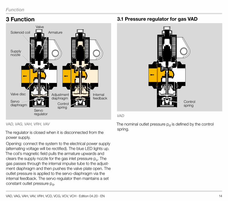
Armature
Valve disc Adjustmentdiaphragm
Servodiaphragm
Internalfeedback
Controlspring
Solenoid coil
Supplynozzle
Servoregulator
Valve
VAD, VAG, VAH, VRH, VAV
The regulator is closed when it is disconnected from the power supply.
Opening: connect the system to the electrical power supply (alternating voltage will be rectified). The blue LED lights up. The coil’s magnetic field pulls the armature upwards and clears the supply nozzle for the gas inlet pressure pu. The gas passes through the internal impulse tube to the adjust-ment diaphragm and then pushes the valve plate open. The outlet pressure is applied to the servo-diaphragm via the internal feedback. The servo regulator then maintains a set constant outlet pressure pd.
3 .1 Pressure regulator for gas VAD
Controlspring
VAD
The nominal outlet pressure pd is defined by the control spring.

VAD, VAG, VAH, VAV, VRH, VCD, VCG, VCV, VCH · Edition 04.20 · EN 15
Function
3 .2 Air/gas ratio control VAG
psa
pd
Zero point setting N /zero point spring
VAG
The air/gas ratio control VAG controls the outlet pressure pd depending on the variable air control pressure psa.
The ratio of gas pressure to air pressure remains constant: 1:1. The VAG is suitable for a turndown up to 10:1.
If the burner operates at low-fire rate, the gas/air mixture can be changed by adjusting the zero point spring “N”.
3 .3 Flow rate regulators VAH, VRH
psa
psa-
pd-
pd
Internal feedback
Zero point setting N /zero point spring
VAH (VRH: no valve)
The flow rate regulators VAH, VRH control the gas flow rate depending on the variable air flow rate. The ratio of gas flow rate to air flow rate remains constant. If the burner operates at low-fire rate, the gas/air mixture can be changed by ad-justing the zero point spring “N”.
In addition, flow rate regulator VAH is designed as a gas so-lenoid valve and shuts off the gas or air supply safely.

VAD, VAG, VAH, VAV, VRH, VCD, VCG, VCV, VCH · Edition 04.20 · EN 16
Function
3 .4 Variable air/gas ratio control VAV
pd
psc
psa
Air diaphragm
Transmission ratio VZero point setting N /
zero point spring
Internalfeedback
Adjustment diaphragm
Servo diaphragm
VAV
The servo regulator maintains a set constant outlet pres-sure pd. The variable air/gas ratio control VAV controls the outlet pressure pd depending on the variable air control pressure psa. The ratio of gas pressure to air pressure re-mains constant.
The settings N and V can be changed and read off from both sides of the unit using the adjusting screws.
The ratio of gas pressure to air pressure at low-fire rate can be changed by adjusting the zero point setting N. By turning the adjusting screw “N”, the force of the zero point
spring and thus the zero point is changed by ± 1.5 mbar (0.6 "WC), see page 32 (Project planning information).
The high-fire rate is set by turning the adjusting screw “V” until the required flue gas values are achieved, see page 32 (Project planning information). The ratio of gas pres-sure to air pressure can be set from 0.6:1 to 3:1.
The settings N and V can influence each other and must be repeated if necessary.
The outlet pressure pd is applied to the servo diaphragm via the internal feedback. The combustion chamber control pressure psc is transmitted to the space under the air and servo diaphragms via an impulse line.
The pressure differential psa - psc is achieved on the air diaphragm and the pressure differential pd - psc on the servo diaphragm. This ensures that pressure fluctuations in the combustion chamber can be compensated. The flue gas values remain constant in the case of fluctua-tions in the combustion chamber pressure (pd - psc) = (psa - psc) × V + N.

VAD, VAG, VAH, VAV, VRH, VCD, VCG, VCV, VCH · Edition 04.20 · EN 17
Function
3 .5 Pressure regulator with gas solenoid valve VAx . .S and closed position indicator
1 COM
2 NOValve open
3 NCValve closed
VAx..S
Opening: when the pressure regulator is opened, the closed position indicator switches. The visual position indi-cator is activated. The “open” signal is marked in red. The double valve seat opens to release the volume of gas.
Closing: the pressure regulator VAx is disconnected from the voltage supply and the closing spring presses the dou-ble valve plate on to the valve seat. The closed position indicator switches. The visual position indicator is white for
“closed”.
The actuator cannot be rotated on a pressure regulator with a closed position indicator.
NOTE: NFPA 86 – The safety shut-off valve VAS..S must be fitted with an overtravel switch with a visual position indicator, and the burner-side pressure regulator with gas solenoid valve VAx..S must be fitted with a closed position indicator. One gas solenoid valve must be verifiably closed. The closed position can be verified using the proof of clo-sure switch of the gas solenoid valve VAS..S.

VAD, VAG, VAH, VAV, VRH, VCD, VCG, VCV, VCH · Edition 04.20 · EN 18
Function
3 .6 Connection diagramWiring to EN 60204-1.
Connection diagram for VAx..S with closed position indica-tor, see page 17 (Pressure regulator with gas solenoid valve VAx..S and closed position indicator).
Further connection options, see Operating instructions VAD, VAG, VAV, VAH... at www.docuthek.com.
VAx with M20 cable gland
L1 (+)
N (–)
VAx with plug
1 = N (-)
2 = L1 (+)
VAS with VAD/VAG/VAH/VAV with M20 cable gland
L1V1 (+)
N (-)
L1V2 (+)
VAS with VAD/VAG/VAH/VAV with plug
2 = L1V1 (+)
1 = N (-)
3 = L1V2 (+)A

VAD, VAG, VAH, VAV, VRH, VCD, VCG, VCV, VCH · Edition 04.20 · EN 19
Flow rate
4 Flow rate
4 .1 Calculating the nominal sizeA web app for calculating the nominal size is available at www.adlatus.org.

VAD, VAG, VAH, VAV, VRH, VCD, VCG, VCV, VCH · Edition 04.20 · EN 20
Flow rate
4 .2 VAD
∆p
[inch
WC
]
Qn [SCFH]100 400 600 4000 60001000 200020 30 40 50 200 3006015 80
0,8
1
2
3
4
56
8
10
20
30
40
5060
80
100
200
∆p
[mba
r]
5
8
3
20
10
30
40
80
60
300
400
50
0,4 0,6 1 2 3 4 5 80,8 10 20 30 4020,3 60 100 200
100
200
500
0,4 0,6 0,8 1 2 3 4 5 6 8 10 20 30 40
0,4 0,6 0,8 1 2 3 4 5 6 8 10
200
80 10020 300,3
0,3Qn [m3/h]
0,2
5060 80 100
40 5060
VAD
1..B
P1P2
VAD
120
..AVA
D 1
25..A
VAD
2..A
1
3
2
1
VAD
3..A
1 = natural gas (ρ = 0.80 kg/m3) 2 = propane (ρ = 2.01 kg/m3) 3 = air (ρ = 1.29 kg/m3)
The characteristic flow rate curves have been measured with the specified flanges and a fitted strainer. If two or more valves are combined, the pressure loss of each addi-tional valve drops by approx. 5%.

VAD, VAG, VAH, VAV, VRH, VCD, VCG, VCV, VCH · Edition 04.20 · EN 21
Flow rate
Selection example for VADGas type: natural gas Inlet pressure pu = 80 mbar Outlet pressure pd = 60 mbar Desired control ratio from high-fire to low-fire rate RV = 10:1 High-fire rate: ∆p = pu - pd = 20 mbar -> point P1 Low-fire rate: -> point P2: Qmin. = 2.6 m3/h for ∆p = 20 mbar RV = Qmax. / Qmin. = 11.5:1
Point P1 and point P2 must be within the working range of a unit size. We recommend that you select the smallest size to achieve the best control properties.

VAD, VAG, VAH, VAV, VRH, VCD, VCG, VCV, VCH · Edition 04.20 · EN 22
Flow rate
4 .3 VAG, VAH, VRH, VAV
∆p
[inch
WC
]
Qn [SCFH]100 400 600 4000 60001000 200020 30 40 50 200 3006015 80
0,8
1
2
3
4
56
8
10
20
30
40
5060
80
100
200
∆p
[mba
r]
5
8
3
20
10
30
40
80
60
300
400
50
0,4 0,6 1 2 3 4 5 80,8 10 20 30 4020,3 60 100 200
100
200
500
0,4 0,6 0,8 1 2 3 4 5 6 8 10 20 30 40
0,4 0,6 0,8 1 2 3 4 5 6 8 10
200
80 10020 300,3
0,3Qn [m
3/h]
0,2
5060 80 100
40 5060
= pd min < 5 mbar
VAG
/VxH
/VAV
1..B
VAG
/VxH
/VAV
120
..A
VAG
/VxH
/VAV
125
..A
P1
P2
VAG
/VxH
/VAV
2..A
1
3
2
1
VAG
/VxH
/VAV
3..A
1 = natural gas (ρ = 0.80 kg/m3) 2 = propane (ρ = 2.01 kg/m3) 3 = air (ρ = 1.29 kg/m3)
The characteristic flow rate curves have been measured with the specified flanges and a fitted strainer. If two or more valves are combined, the pressure loss of each addi-tional valve drops by approx. 5%.

VAD, VAG, VAH, VAV, VRH, VCD, VCG, VCV, VCH · Edition 04.20 · EN 23
Flow rate
Selection example for VAG, VAH, VRH, VAVGas type: natural gas Flow rate Qmax. = 30 m3/h Inlet pressure pu = 80 mbar Outlet pressure pd max. VAG = 60 mbar Desired control ratio from high-fire to low-fire rate RV = 10:1 High-fire rate: ∆p = pu - pd = 20 mbar -> point P1 Low-fire rate: pd min. = pd max. / RV2 = 0.6 mbar Qmin. = Qmax. / RV = 3 m3/h ∆p = pu - pd min. = 79.4 mbar -> point P2, selected: VAG 120..A
Point P1 and point P2 must be within the working range of a unit size. We recommend that you select the smallest size to achieve the best control properties.

VAD, VAG, VAH, VAV, VRH, VCD, VCG, VCV, VCH · Edition 04.20 · EN 24
Flow rate
4 .4 Zero governor VAG . .N
∆p
[inch
WC
]
Qn [SCFH]100 400 600 4000 60001000 200020 30 40 50 200 3006015 80
0,8
1
2
3
4
56
8
10
20
30
40
5060
80
100
200
∆p
[mba
r]
5
8
3
20
10
30
40
80
60
300
400
50
0,4 0,6 2 3 4 5 80,8 10 20 30 4020,3 60 100 200
100
200
500
0,4 0,6 0,8 1 2 3 4 5 6 8 10 20 30 40
0,4 0,6 0,8 1 2 3 4 5 6 8 10
200
80 10020 300,3
0,3Qn [m
3/h]
0,2
5060 80 100
40 5060
VAG
1..N
P1
VAG
125
..N
VAG
120
..N
VAG
2..N
P2
1
3
2
1
VAG
3..N
1 = natural gas (ρ = 0.80 kg/m3) 2 = propane (ρ = 2.01 kg/m3) 3 = air (ρ = 1.29 kg/m3)
The characteristic flow rate curves have been measured with the specified flanges and a fitted strainer. If two or more valves are combined, the pressure loss of each addi-tional valve drops by approx. 5%.

VAD, VAG, VAH, VAV, VRH, VCD, VCG, VCV, VCH · Edition 04.20 · EN 25
Flow rate
Selection example for VAG . .NGas type: natural gas Flow rate Qmax. = 30 m3/h Inlet pressure pu = 20 mbar Outlet pressure pd max. = 0 mbar (atmospheric pressure) Desired control ratio from high-fire to low-fire rate RV = 10:1 High-fire rate: ∆p = pu - pd = 20 mbar -> point P1 Low-fire rate: -> point P2: Qmin. = 2.4 m3/h for ∆p = 20 mbar RV = Qmax. / Qmin. = 12.3:1
Point P1 and point P2 must be within the working range of a unit size. We recommend that you select the smallest size to achieve the best control properties.
4 .4 .1 Calculating the nominal sizeA web app for calculating the nominal size is available at www.adlatus.org.

VAD, VAG, VAH, VAV, VRH, VCD, VCG, VCV, VCH · Edition 04.20 · EN 26
Selection
5 Selection
5 .1 ProFiA web app selecting the correct product is available at www.adlatus.org.

VAD, VAG, VAH, VAV, VRH, VCD, VCG, VCV, VCH · Edition 04.20 · EN 27
Selection
5 .2 VAD selection table
Option VAD 115 VAD 120, VAD 125 VAD 240 VAD 350DN – inlet 15, 20, 25 15, 20, 25 25, 32, 40, 50 40, 50, 65DN – outlet 15, 20, 25 15, 20, 25 40 50Pipe connection R, N R, N R, N, F R, N, FOpening properties /N /N /N /NMains voltage W, Y, Q, P, K W, Y, Q, P, K W, Y, Q, P, K W, Y, Q, P, KFeedback1) S, G S, G S, G S, GViewing side R, L R, L R, L R, L
Electrical connection M20, plug, plug with socket
M20, plug, plug with socket
M20, plug, plug with socket
M20, plug, plug with socket
Outlet pressure pd -25, -50, -100 -25, -50, -100 -25, -50, -100 -25, -50, -100Valve seat B A A A
Accessories, right
Screw plug, test nipple,
DG 17–3002), VBY1), VAS 1
Screw plug, test nipple,
DG 17–3002), VBY1), VAS 1
Screw plug, test nipple,
DG 17–3002), VAS 11)
Screw plug, test nipple,
DG 17–3002), VAS 11)
Accessories, left
Screw plug, test nipple,
DG 17–3002), VBY1),VAS 1
Screw plug, test nipple,
DG 17–3002), VBY1), VAS 1
Screw plug, test nipple,
DG 17–3002), VAS 11)
Screw plug, test nipple,
DG 17–3002), VAS 11)
1) Closed position indicator and bypass/pilot gas valve cannot be fitted together on the same side. 2) Specify the test point for inlet pressure pu or outlet pressure pd.
Order exampleVAD 240R/NW-100A

VAD, VAG, VAH, VAV, VRH, VCD, VCG, VCV, VCH · Edition 04.20 · EN 28
Selection
5 .3 VAG, VAH, VAV selection table
Option VAG/VAH/VAV 115 VAG/VAH/VAV 120, VAD/VAH/VAV 125 VAG/VAH/VAV 240 VAG/VAH/VAV 350
DN – inlet –, 15, 20, 25 –, 15, 20, 25 –, 25, 32, 40, 50 –, 40, 50, 65DN – outlet 15, 20, 25 15, 20, 25 40 50Pipe connection R, N R, N R, N, F R, N, FOpening properties /N /N /N /NMains voltage W, Y, Q, P, K W, Y, Q, P, K W, Y, Q, P, K W, Y, Q, P, KFeedback1) S, G S, G S, G S, GViewing side R, L R, L R, L R, L
Electrical connection M20, plug, plug with socket
M20, plug, plug with socket
M20, plug, plug with socket
M20, plug, plug with socket
Valve seat B A A AConnection kit for VAG E, K, A, N E, K, A, N E, K, A, N E, K, A, NConnection kit for VAH E, A E, A E, A E, AConnection kit for VAV E, K, A E, K, A E, K, A E, K, A
Accessories, rightScrew plug, test nipple,
DG 17–3002), VBY1), VAS 1
Screw plug, test nipple,
DG 17–3002), VBY1), VAS 1
Screw plug, test nipple,
DG 17–3002), VAS 11)
Screw plug, test nipple,
DG 17–3002), VAS 11)
Accessories, leftScrew plug, test nipple,
DG 17–3002), VBY1), VAS 1
Screw plug, test nipple,
DG 17–3002), VBY1), VAS 1
Screw plug, test nipple,
DG 17–3002), VAS 11)
Screw plug, test nipple,
DG 17–3002), VAS 11)
1) Closed position indicator and bypass/pilot gas valve cannot be fitted together on the same side. 2) Specify the test point for inlet pressure pu or outlet pressure pd.
Order exampleVAG 240R/NWAE

VAD, VAG, VAH, VAV, VRH, VCD, VCG, VCV, VCH · Edition 04.20 · EN 29
Selection
5 .4 VRH selection table
Option VRH 115 VRH 120, VRH 125 VRH 240 VRH 350DN – inlet -, 15, 20, 25 -, 15, 20, 25 -, 25, 32, 40, 50 -, 40, 50, 65DN – outlet 15, 20, 25 15, 20, 25 40 50Pipe connection R, N R, N R, N, F R, N, FInlet pressure pu 05 05 05 05Valve seat B A A AConnection kit E, A E, A E, A E, A
Accessories, right Screw plug, test nipple
Screw plug, test nipple
Screw plug, test nipple
Screw plug, test nipple
Accessories, left Screw plug, test nipple
Screw plug, test nipple
Screw plug, test nipple
Screw plug, test nipple
Order exampleVRH 240R05AE/PP/PP

VAD, VAG, VAH, VAV, VRH, VCD, VCG, VCV, VCH · Edition 04.20 · EN 30
Selection
5 .5 Type codeVAD Pressure regulator with solenoid valve
VAG Air/gas ratio control with solenoid valve
VAH Flow rate regulator with solenoid valve
VAV Variable air/gas ratio control with solenoid valve
VRH Flow rate regulator
1-3 Sizes
15–50 Inlet and outlet flange nominal size
R Rp internal thread
F Flange to ISO 7005
/N Quick opening, quick closing
W Mains voltage 230 V AC, 50/60 Hz
Y Mains voltage 200 V AC, 50/60 Hz
Q Mains voltage 120 V AC, 50/60 Hz
P Mains voltage 100 V AC, 50/60 Hz
K Mains voltage 24 V DC
SR Closed position switch with visual position indicator, right
SL Closed position switch with visual position indicator, left
GR Closed position switch for 24 V and visual position indicator, right
GL Closed position switch for 24 V and visual position indicator, left
-25 Outlet pressure pd for VAD: 2.5–25 mbar
-50 Outlet pressure pd for VAD: 20–50 mbar
-100 Outlet pressure pd for VAD: 35–100 mbar
A Standard valve seat
B Reduced valve seat
E VAG, VAV, VAH, VRH: connection for air control pressure: compression fitting
K VAG, VAV: connection for air control pressure: plastic hose coupling
A VAG, VAV, VAH, VRH: connection for air control pressure: 1/8" NPT adapter
N VAG: zero governor
VRH: no solenoid valve

VAD, VAG, VAH, VAV, VRH, VCD, VCG, VCV, VCH · Edition 04.20 · EN 31
Selection
5 .6 Accessory selection
Pressure test nipples
Screwplugs Pressure
switchDG..C
Tightness control TC
Bypass/pilot gas valve VAS
Bypass/pilot gas valve VBY for size 1
Closed position switch
Plug with socket
Plug
Modularly configurable with:
• Screw plugs
• Pressure test nipples
• Pressure switch DG..C for inlet and/or outlet pressure
• Tightness control TC
• Bypass/pilot gas valve VBY 8 for size 1
• Bypass/pilot gas valve VAS 1
• Attachment block for the connection of a pressure gauge, for example
For further information, see page 36 (Accessories).

VAD, VAG, VAH, VAV, VRH, VCD, VCG, VCV, VCH · Edition 04.20 · EN 32
Project planning information
6 Project planning information
6 .1 Test pointsFor further information on outlet pressure, air control pres-sure and combustion chamber control pressure, see page 44 (Technical data).
The inlet pressure pu and the outlet pressure pd can be measured on both sides of the valve body.
pu pd
pd
To increase the control accuracy, an external impulse line can be connected, instead of pressure test point pd.
VAD
VADpd
(psa)
Test point for the gas outlet pressure pd on the regulator body. A combustion chamber control line (psc) can be con-nected to connection psa for maintaining a constant burner capacity.
VAG
VAGpsa
pdpsa
Additional test point for the air control pressure psa on the regulator body. For burners which are operated with excess air, the values for pd and psa may be below the limit. No sit-uation which would jeopardize safety must arise. Avoid CO formation.
VAV
VAV
pdpsa
psc
Test point for the outlet pressure pd on the regulator body.
VAH
VAH, VRHpsa
psa-
psapdpd-
pd-
psa-
Additional test points for the outlet pressure pd- and the air control pressure psa/psa- on the regulator body. A gas/air mixture may be applied at the psa- connection for the air control pressure.

VAD, VAG, VAH, VAV, VRH, VCD, VCG, VCV, VCH · Edition 04.20 · EN 33
Project planning information
6 .2 InstallationVAD, VAG,VAH, VRH
VAD, VAG,VAV, VAH,VRH
Sealing material and thread cuttings must not be allowed to get into the valve housing. Install a filter upstream of every system.
Always install an activated carbon filter upstream of the regulator when air is the medium. Otherwise, the ageing of elastomer materials will be accelerated.
The pipe system must be designed in such a way so as to avoid strain at the connections.
Do not store or install the unit in the open air.
>20 mm>0.79"
The device must not be in contact with masonry. Minimum clearance 20 mm (0.79 inch).
Ensure that there is sufficient space for installation, adjust-ment and maintenance work. Minimum clearance of 25 cm (9.8 inch) above the black solenoid actuator.
If more than three valVario controls are installed in line, the controls must be supported.
The seals in some gas compression fittings are approved for temperatures of up to 70°C (158°F). This temperature limit will not be exceeded if the flow through the pipe is at least 1 m3/h (35.31 SCFH) of gas and the maximum ambient temperature is 50°C (122°F).
In the case of a VCx combination, it is recommended to always install the bypass/pilot gas valve on the rear of the second valve and the tightness control on the viewing side of the first valve, together with the connection box.

VAD, VAG, VAH, VAV, VRH, VCD, VCG, VCV, VCH · Edition 04.20 · EN 34
Project planning information
6 .2 .1 Installation positionVAD, VAG, VAH: black solenoid actuator in the vertical up-right position or tilted up to the horizontal, not upside down. VRH: in the vertical upright position or tilted up to the hori-zontal, not upside down.
VAV: Installation in the vertical position only, black solenoid actuator in the vertical upright position.
VAD, VAG,VAH, VRH
VAD, VAG,VAV, VAH,VRH
For VAG/VAH/VRH in the horizontal position with modulat-ing control: min. inlet pressure pu min. = 80 mbar (32 "WC).
To ensure that the air/gas ratio control VAG, the flow rate regulator VAH, VRH or the variable air/gas ratio control VAV can react quickly when the load is changed, the impulse line for the air control pressure psa and for VAV, the impulse line for the combustion chamber control pressure psc should be kept as short as possible. The tube internal di-ameter for the impulse line must always be ≥ 3.9 mm (0.15").
VAH, VRHIt is not permitted to install a gas solenoid valve VAS down-stream of flow rate regulator VAH, VRH and upstream of fine-adjusting valve VMV. The VAS would no longer be able to perform its function as a second safety valve if installed in the above-mentioned position.
M
VMVVAHVASVAS
pd-
psa-psa
VMVVAH
pd-
psa-psa
The measuring orifice in the air line for impulse lines psa and psa- must always be installed downstream of the air control valve.
VAVThe impulse line for the combustion chamber control pres-sure psc must be fitted so that no condensation can enter the pressure regulator, but rather flows back into the com-bustion chamber.
6 .3 Setting the low-fire rate on VAG, VAH, VRH, VAV
-1
0 +0,5-0,5
–
+1-1,5
mbar
+1,50,6
1 1,52
3
N V
+ +–
+3
0 -1,5+1,5
–
-3+5
mbar
-5
N
+
VAG, VAH, VRH VAV
If the burner operates at low-fire rate, the gas/air mixture can be changed using the parallel shift of the characteristic curve by turning the adjusting screw “N”.
Adjusting range at low fire: VAG, VAH, VRH: -5 to +5 mbar (-1.95 to +1.95 "WC). VAV: -1.5 to +1.5 mbar (-0.6 to +0.6 "WC).

VAD, VAG, VAH, VAV, VRH, VCD, VCG, VCV, VCH · Edition 04.20 · EN 35
Project planning information
6 .4 Setting the high-fire rate on VAV
+N+V
-V
-N
VAV
psa [mbar]
p d [m
bar]
To set the high-fire rate, the transmission ratio is changed using the adjusting screw “V” until the required flue gas val-ues are achieved.
Transmission ratio: V = pd:psa = 0,6:1 to 3:1.
The settings N and V can influence each other and must be repeated if necessary.
CalculationWith connection to the combustion chamber control pres-sure psc: (pd - psc) = V × (psa - psc) + N
If the combustion chamber control pressure psc is not con-nected: pd = V × psa + N
6 .5 Electrical connectionUse temperature-resistant cable (> 90°C) for the electrical connection.
The solenoid actuator heats up during operation. Surface temperature approx. 85°C (185°F) pursuant to EN 60730-1.
In the case of double solenoid valves, the position of the connection box can only be changed by removing the actu-ator and reinstalling it rotated by 90° or 180°. The solenoid actuator cannot be rotated on solenoid valves with proof of closure switch VCx..S or VCx..G.

VAD, VAG, VAH, VAV, VRH, VCD, VCG, VCV, VCH · Edition 04.20 · EN 36
Accessories
7 Accessories
7 .1 Pressure switch for gas DG . .CMonitoring the inlet pressure pu: the electrical plug of the pressure switch for gas points towards the inlet flange. Monitoring the outlet pressure pd: the electrical plug of the pressure switch for gas points towards the outlet flange.
pu
pd
Scope of delivery: 1 x pressure switch for gas, 2 x retaining screws, 2 x sealing rings.
Also available with gold-plated contacts for voltages of 5 to 250 V.
DG . .VC
50
6420.527
37
Type Adjusting range [mbar]DG 17VC 2 to 17DG 40VC 5 to 40
Type Adjusting range [mbar]DG 110VC 30 to 110DG 300VC 100 to 300
DG . .VCTWith AWG 18 connection conductors
2.5"
1.5"
2.5"1.1"
0.8"
Type Adjusting range ["WC]DG 17VCT 0.8 to 6.8DG 40VCT 2 to 16DG 110VCT 12 to 44DG 300VCT 40 to 120
7 .2 DG . .C fastening set for VAx 1–3Order No.: 74922376, scope of delivery: 2 x retaining screws, 2 x sealing rings.

VAD, VAG, VAH, VAV, VRH, VCD, VCG, VCV, VCH · Edition 04.20 · EN 37
Accessories
7 .3 Bypass/pilot gas valve VAS 1
7 .3 .1 Flow rate, VAS 1 attached to VAx 1, VAx 2, VAx 3
The characteristic flow rate curves have been measured for bypass valve VAS 1 with connection pipe diameter 1 to 10 mm (0.04–0.4") and for the pilot gas valve with 10 mm connection pipe.
2
3
456
810
20
30
405060
80100
∆p
[mba
r]0,05 0,1 0,2 0,3 0,5 0,8 1 2 3 4 5
1
3
2
Qn [m3/h]
1
0,1
0,2
0,3
0,40,5
0,8
0,03
0,02
6 8 10
0,05 0,1 0,2 0,3 0,5 0,8 1 2 3 4 50,03 6 8 10
20
0,05 0,1 0,2 0,3 0,5 0,8 1 2 3 4 50,03 6 8 10 20
30
Δp
[inch
WC
]
1
2
3
456
810
20
30
40
0.4
0.04
0.06
0.08
0.1
0.2
0.3
0.50.6
0.8
Qn [SCFH]10 40 60 100 200 3001 500 10002 3 4 5
120 306 8
21 3 4 5 6 7 8 910
Pilo
t gas
val
ve, 1
0 m
m (0
,4")
con
nect
ion
pipe
dia
met
er
1 = natural gas (ρ = 0.80 kg/m3) 2 = propane (ρ = 2.01 kg/m3) 3 = air (ρ = 1.29 kg/m3)

VAD, VAG, VAH, VAV, VRH, VCD, VCG, VCV, VCH · Edition 04.20 · EN 38
Accessories
7 .3 .2 Scope of delivery of VAS 1 for VAx 1, VAx 2, VAx 3
A
VAS 1 → VAx 1 VAS 1 → VAx 2, VAx 3
C
A
D
F
B
E
C
D
F
B
E
A 1 x bypass/pilot gas valve VAS 1, B 4 x O-rings, C 4 x double nuts for VAS 1 –> VAx 1, C 4 x spacer sleeves for VAS 1 –> VAx 2/VAx 3, D 4 x connection parts, E 1 x mounting aid.
Pilot gas valve VAS 1: F 1 x connection pipe, 1 x sealing plug, if the pilot gas valve has a threaded flange on the outlet side.
Bypass valve VAS 1: F 2 x connection pipes, if the bypass valve has a blind flange on the outlet side. Standard: Ø 10 mm.
Other connection pipes ( F) with bypass diameter as of 1 mm are available.
Ø Order No .1 mm 749238772 mm 749239103 mm 749239114 mm 749239125 mm 749239136 mm 749239147 mm 749239158 mm 749239169 mm 7492391710 mm 74923918

VAD, VAG, VAH, VAV, VRH, VCD, VCG, VCV, VCH · Edition 04.20 · EN 39
Accessories
7 .4 Bypass/pilot gas valve VBY 8
7 .4 .1 Flow rate, VBY
VBY 8..D
VAx 1
+
-
VBY 8..05
VAx 1
VBY 8 . .D
The flow rate can be set by turning the flow rate restrictor (4 mm/0.16" hexagon socket) ¼ of a turn. Flow rate: 10 to 100%.
VBY 8 . .05
The flow is routed through a 0.5 mm (0.02") nozzle and thus has a fixed characteristic flow rate curve. Adjustment is not possible.
2
0,1
0,2
0,3
0,5
0,81
3
456
810
20
30
405060
80100
Δp
[mba
r]1
3
20,1 0,2 0,3 0,5 1 2 30,01 0,03 4
Qn [m3/h]
0,2 0,3 0,5 1 2
0,1 0,2 0,5
0,02 0,06
0,02
0,02 0,06 1
0,010,006 0,05 0,1
0,01
0,003
0,006 2 3
VBY 8..DVBY 8..05
Δp
[inch
WC
]
1
2
3
456
810
20
30
40
0.40.50.6
0.8
1
Qn [SCFH]10 40 60 1005 2081 2 30,40,2
0.1
0.2
0.3
0.040.050.06
0.08
Adjusting range
1 = natural gas (ρ = 0.80 kg/m3) 2 = propane (ρ = 2.01 kg/m3) 3 = air (ρ = 1.29 kg/m3)

VAD, VAG, VAH, VAV, VRH, VCD, VCG, VCV, VCH · Edition 04.20 · EN 40
Accessories
7 .4 .2 Technical data VBY 8 Inlet pressure pu max: 500 mbar (7 psig).
Ambient temperature: 0 to +60 °C (32 to 140 °F), no condensation permitted.
Storage temperature: 0 to +40 °C (32 to 104 °F).
Power consumption: 24 V DC = 8 W, 120 V AC = 8 W, 230 V AC = 9,5 W.
Enclosure: IP 54.
7 .4 .3 Scope of delivery of VBY for VAx 1
B
C
AVBY 8
VAx 1
55
(2.17")40(1.57")
70 (2.76")
80(3.15")
Rp ¼(pilot gas valve)
Scope of delivery of VBY6 8I as bypass valve A 1 x bypass valve VBY 8I, B 2 x retaining screws with 4 x O-rings: both retaining screws have a bypass orifice, C grease for O-rings.
Scope of delivery of VBY6 8R as pilot gas valve A 1 x pilot gas valve VBY 8R, B 2 x retaining screws with 5 x O-rings: one retaining screw has a bypass orifice (2 x O-rings), the other does not (3 x O-rings), C grease for O-rings.
7 .4 .4 Type codeVBY Gas valve
8 Nominal size
I For internal gas pick-up as bypass valve
R For external gas pick-up as pilot gas valve
Q Mains voltage 120 V AC, 50/60 Hz
K Mains voltage 24 V DC
W Mains voltage 230 V AC, 50/60 Hz
6L Electrical connection via plug and socket with LED
-R Attachment side of main valve: to the right
-L Attachment side of main valve: to the left
B Enclosed (separate packing unit)
05 Nozzle: 0.5 mm
D With flow adjustment

VAD, VAG, VAH, VAV, VRH, VCD, VCG, VCV, VCH · Edition 04.20 · EN 41
Accessories
7 .5 Pressure test nipples
Scope of delivery
1 x test nipple with 1 x profiled sealing ring, Rp 1/4: Order No. 74923390.
1 x test nipple (steel) with 1 x profiled sealing ring (Viton), 1/4 NPT: Order No. 74921869.
7 .6 Cable gland setWhen wiring double solenoid valve VCx 1–3, the connection boxes are to be connected using a cable gland set. The cable gland set can only be used if the connection box-es are at the same height and on the same side and if both valves are equipped either with or without a proof of closure switch.
VCx 1 VCx 2VCx 3
VA 1, Order No. 74921985, VA 2, Order No. 74921986, VA 3, Order No. 74921987.
7 .7 Attachment block VA 1–3For locked installation of pressure gauge or other accesso-ries on the gas solenoid valve VAS 1–3.
BA
C
Attachment block Rp 1/4, Order No. 74922228, Attachment block 1/4 NPT, Order No. 74926048.
Scope of delivery: A 1 x attachment block, B 2 x self-tapping screws for installation, C 2 x O-rings.

VAD, VAG, VAH, VAV, VRH, VCD, VCG, VCV, VCH · Edition 04.20 · EN 42
Accessories
7 .8 Seal set for sizes 1–3When retrofitting accessories or a second valVario control or when servicing, we recommend replacing the seals.
CA B
C
E
D
VAS 1–3
VA 1, Order No. 74921988, VA 2, Order No. 74921989, VA 3, Order No. 74921990.
Scope of delivery: A 1 x double block seal, B 1 x retaining frame, C 2 x O-rings (flange), D 2 x O-rings (pressure switch),
for test nipple/screw plug: E 2 x sealing rings (flat sealing), 2 x profiled sealing rings.
VCS 1-3
VA 1, Order No. 74924978, VA 2, Order No. 74924979, VA 3, Order No. 74924980.
Scope of delivery: A 1 x double block seal, B 1 x retaining frame.
7 .9 Differential pressure orifice
Size Pipe DN Differential pressure orifice
Colour Outlet dia . Order No .
1 15 yellow 18.5 mm 0.67" 749222381 20 green 25 mm 0.98" 749222391 25 transparent 30 mm 1.18" 749222402 40 transparent 46 mm 1.81" 749249073 50 transparent 58 mm 2.28" 74924908
If pressure regulator VAD/VAG/VAV 1 is retrofitted upstream of gas solenoid valve VAS 1, a DN 25 differential pressure orifice with outlet opening d = 30 mm (1.18") must be insert-ed at the outlet of the pressure regulator.
In the case of pressure regulator VAx 115 or VAx 120, the DN 25 differential pressure orifice must be ordered sepa-rately and retrofitted, Order No. 74922240.

VAD, VAG, VAH, VAV, VRH, VCD, VCG, VCV, VCH · Edition 04.20 · EN 43
Accessories
7 .10 Measuring orifice VMO
The measuring orifice VMO is designed to reduce the gas and air flow rates and is installed downstream of the valVar-io control. The measuring orifice is available with Rp internal thread (NPT internal thread) or flange to ISO 7005.
Technical Information VMO, see www.docuthek.com.
7 .11 Filter module VMF
Using the filter module VMF, the gas flow upstream of the gas solenoid valve VAS and the air/gas ratio control is cleaned. The filter module is available with Rp internal thread (NPT internal thread) or flange to ISO 7005 and can also be supplied with fitted pressure switch as an option.
Technical Information VMF, see www.docuthek.com.
7 .12 Fine-adjusting valve VMV
The flow rate is set using the fine-adjusting valve VMV. The fine-adjusting valve is available with Rp internal thread (NPT internal thread) or flange to ISO 7005.
Technical Information VMV, see www.docuthek.com.
7 .13 Gas control line
pd-
Fine-adjusting valve VMV can be installed on the flow rate regulator VAH for fine adjustment of the gas flow rate.
The gas control line for gas outlet pressure pd- is available with two 1/8" compression fittings.
Size 1: Order No. 74924458, Size 2: Order No. 74924459, Size 3: Order No. 74926055.
VAD, VAG, VAH, VAV, VRH, VCD, VCG, VCV, VCH · Edition 04.20 · EN 44
Technical data
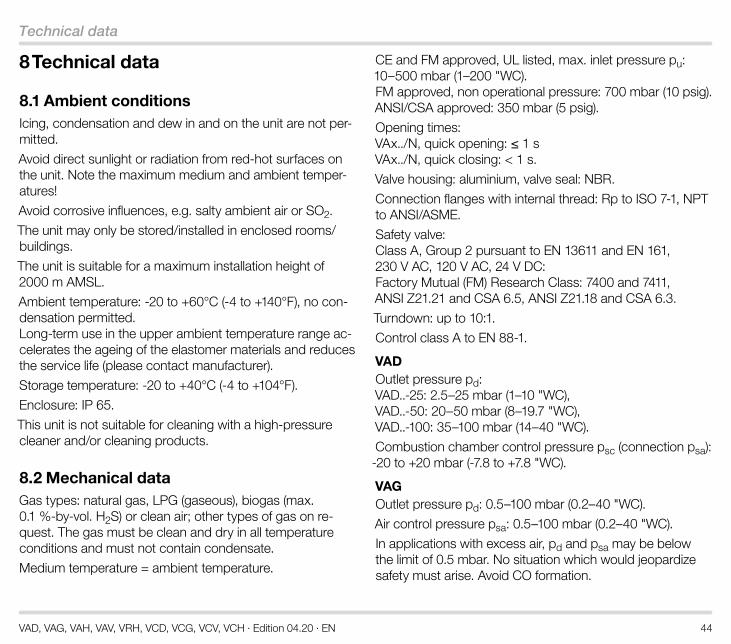
8 Technical data
8 .1 Ambient conditionsIcing, condensation and dew in and on the unit are not per-mitted.
Avoid direct sunlight or radiation from red-hot surfaces on the unit. Note the maximum medium and ambient temper-atures!
Avoid corrosive influences, e.g. salty ambient air or SO2.
The unit may only be stored/installed in enclosed rooms/buildings.
The unit is suitable for a maximum installation height of 2000 m AMSL.
Ambient temperature: -20 to +60°C (-4 to +140°F), no con-densation permitted. Long-term use in the upper ambient temperature range ac-celerates the ageing of the elastomer materials and reduces the service life (please contact manufacturer).
Storage temperature: -20 to +40°C (-4 to +104°F).
Enclosure: IP 65.
This unit is not suitable for cleaning with a high-pressure cleaner and/or cleaning products.
8 .2 Mechanical dataGas types: natural gas, LPG (gaseous), biogas (max. 0.1 %-by-vol. H2S) or clean air; other types of gas on re-quest. The gas must be clean and dry in all temperature conditions and must not contain condensate.
Medium temperature = ambient temperature.
CE and FM approved, UL listed, max. inlet pressure pu: 10–500 mbar (1–200 "WC). FM approved, non operational pressure: 700 mbar (10 psig). ANSI/CSA approved: 350 mbar (5 psig).
Opening times: VAx../N, quick opening: ≤ 1 s VAx../N, quick closing: < 1 s.
Valve housing: aluminium, valve seal: NBR.
Connection flanges with internal thread: Rp to ISO 7-1, NPT to ANSI/ASME.
Safety valve: Class A, Group 2 pursuant to EN 13611 and EN 161, 230 V AC, 120 V AC, 24 V DC: Factory Mutual (FM) Research Class: 7400 and 7411, ANSI Z21.21 and CSA 6.5, ANSI Z21.18 and CSA 6.3.
Turndown: up to 10:1.
Control class A to EN 88-1.
VADOutlet pressure pd: VAD..-25: 2.5–25 mbar (1–10 "WC), VAD..-50: 20–50 mbar (8–19.7 "WC), VAD..-100: 35–100 mbar (14–40 "WC).
Combustion chamber control pressure psc (connection psa): -20 to +20 mbar (-7.8 to +7.8 "WC).
VAGOutlet pressure pd: 0.5–100 mbar (0.2–40 "WC).
Air control pressure psa: 0.5–100 mbar (0.2–40 "WC).
In applications with excess air, pd and psa may be below the limit of 0.5 mbar. No situation which would jeopardize safety must arise. Avoid CO formation.

VAD, VAG, VAH, VAV, VRH, VCD, VCG, VCV, VCH · Edition 04.20 · EN 45
Technical data
Adjusting range at low fire: ±5 mbar (±2 "WC).
Transmission ratio of gas to air: 1:1.
The inlet pressure must always be higher than the air control pressure psa + pressure loss ∆p + 5 mbar (2 "WC).
Connection options for air control pressure psa: VAG..K: 1 1/8" coupling for plastic hose (internal dia. 3.9 mm (0.15"), external dia. 6.1 mm (0.24")), VAG..E: 1 1/8" coupling with compression fitting for 6 x 1 tube, VAG..A: 1 1/8" NPT adapter, VAG..N: zero governor with breathing orifice.
VAVOutlet pressure pd: 0.5–30 mbar (0.2–11.7 "WC).
Air control pressure psa: 0.4–30 mbar (0.15–11.7 "WC).
Combustion chamber control pressure psc: -20 to +20 mbar (-7.8 to +7.8 "WC).
Min. control pressure differential psa - psc: 0.4 mbar (0.15 "WC).
Min. pressure differential pd - psc: 0.5 mbar (0.2 "WC).
Adjusting range at low fire: ±1.5 mbar (±0.6 "WC).
Transmission ratio of gas to air: 0.6:1 to 3:1.
The inlet pressure pu must always be higher than the air control pressure psa x transmission ratio V + pressure loss ∆p + 1.5 mbar (0.6 "WC).
Connection of air control pressure psa and combustion chamber control pressure psc: VAV..K: 2 plastic hose couplings (internal dia. 3.9 mm (0.15");
external dia. 6.1 mm (0.24")) or VAV..E: 2 1/8" compression fittings for 6 x 1 tube or VAV..A: 2 1/8" NPT adapters.
VAH, VRHThe inlet pressure must always be higher than the differ-ential air pressure ∆psa + max. gas pressure on burner + pressure loss ∆p + 5 mbar(2 "WC).
Differential air pressure ∆psa (psa - psa-) = 0.6–50 mbar (0.24–19,7 "WC).
Differential gas pressure ∆pd (pd - pd-) = 0.6–50 mbar (0.24–19.7 "WC).
Adjusting range at low fire: ±5 mbar (±2 "WC).
Transmission ratio of gas to air: 1:1.
Connection of the air control pressure psa: VAH..E, VRH..E: 3 1/8" couplings with compression fitting for 6 x 1 tube or VAH..A, VRH..A: 3 1/8" NPT adapters.
8 .3 Electrical dataMains voltage: 230 V AC, +10/-15%, 50/60 Hz; 200 V AC, +10/-15%, 50/60 Hz; 120 V AC, +10/-15%, 50/60 Hz; 100 V AC, +10/-15%, 50/60 Hz; 24 V DC, ±20%.
Power consumption:
Cable gland: M20 x 1.5.

VAD, VAG, VAH, VAV, VRH, VCD, VCG, VCV, VCH · Edition 04.20 · EN 46
Technical data
Electrical connection: cable with max. 2.5 mm2 (AWG 12) or plug with socket to EN 175301-803.
Duty cycle: 100%.
Power factor of the solenoid coil: cos φ = 0.9.
Type Voltage PowerVAx 1 24 V DC 25 WVAx 1 100 V AC 25 W (26 VA)VAx 1 120 V AC 25 W (26 VA)VAx 1 200 V AC 25 W (26 VA)VAx 1 230 V AC 25 W (26 VA)VAx 2, VAx 3 24 V DC 36 WVAx 2, VAx 3 100 V AC 36 W (40 VA)VAx 2, VAx 3 120 V AC 40 W (44 VA)VAx 2, VAx 3 200 V AC 40 W (44 VA)VAx 2, VAx 3 230 V AC 40 W (44 VA)VBY 24 V DC 8 WVBY 120 V AC 8 WVBY 230 V AC 9.5 W
Contact rating of closed position indicator:
Type Voltage Current (resistive load)
min . max .
VAx..S, VCx..S 12–250 V AC, 50/60 Hz 100 mA 3 A
VAx..G, VCx..G 12–30 V DC 2 mA 0.1 A
Switching frequency of closed position indicator: max. 5 x per minute.
Switching current Switching cycles*cos φ = 1 cos φ = 0 .6
0.1 500,000 500,0000.5 300,000 250,0001 200,000 100,0003 100,000 –
* Limited to max. 200,000 cycles for heating systems.

VAD, VAG, VAH, VAV, VRH, VCD, VCG, VCV, VCH · Edition 04.20 · EN 47
Dimensions
9 Dimensions
9 .1 Rp internal thread, ISO flange
VAD, VAG, VAH, VAV VAx..S VAx..F
H1
H2
E
LF
F
H4
Rp ¼(¼” NPT)
L2G
G
H3
B
Type Connection Dimensions [mm] Weight [kg]
Rp DN L L2 E F G H1 H2 H3 H4 BVAx 115 1/2 15 75 – 75 15 – 143 82 161 117 97 1.8VAH 115 1/2 15 75 – 75 15 – 143 100 161 135 97 2VAx 120 3/4 20 91 – 75 23 – 143 82 161 117 97 1.9VAH 120 3/4 20 91 – 75 23 – 143 100 161 135 97 2.1VAx 125 1 25 91 – 75 23 – 143 82 161 117 97 1.9VAH 125 1 25 91 – 75 23 – 143 100 161 135 97 2.1VAx 240 1 1/2 40 127 200 85 29 66 170 112 191 162 125 4.4VAH 240 1 1/2 40 127 200 85 29 66 170 132 191 182 125 4.7VAx 350 2 50 155 230 85 36 74 180 135 201 196 160 6.1VAH 350 2 50 155 230 85 36 74 180 156 201 217 160 6.4

VAD, VAG, VAH, VAV, VRH, VCD, VCG, VCV, VCH · Edition 04.20 · EN 48
Dimensions
9 .2 NPT internal thread, ANSI flange
VAD, VAG, VAH, VAV VAx..S VAx..F
H1
H2
E
LF
F
H4
Rp ¼(¼” NPT)
L2G
G
H3
B
Type Connection Dimensions [inch] Weight [lbs]
NPT DN L L2 E F G H1 H2 H3 H4 BVAx 115 1/2 15 2.9 – 2.9 0.6 – 5.6 3.2 6.3 4.6 3.8 4.0VAH 115 1/2 15 2.9 – 2.9 0.6 – 5.6 3.9 6.3 5.3 3.8 4.4VAx 120 3/4 20 3.6 – 2.9 0.9 – 5.6 3.3 6.3 4.6 3.8 4.2VAH 120 3/4 20 3.6 – 2.9 0.9 – 5.6 3.9 6.3 5.3 3.8 4.6VAx 125 1 25 3.6 – 2.9 0.9 – 5.6 3.3 6.3 4.6 3.8 4.2VAH 125 1 25 3.6 – 2.9 0.9 – 5.6 3.9 6.3 5.3 3.8 4.6VAx 240 1 1/2 40 5.0 7.9 3.3 1.1 2.6 6.7 4.4 7.5 6.4 4.9 9.7VAH 240 1 1/2 40 5.0 7.9 3.3 1.1 2.6 6.7 5.2 7.5 7.2 4.9 10.4VAx 350 2 50 6.1 9.1 3.3 1.4 2.9 7.0 5.3 7.9 7.7 6.3 13.4VAH 350 2 50 6.1 9.1 3.3 1.4 2.9 7.0 6.1 7.9 8.5 6.3 14.1

VAD, VAG, VAH, VAV, VRH, VCD, VCG, VCV, VCH · Edition 04.20 · EN 49
Converting units
10 Converting unitsSee www.adlatus.org

VAD, VAG, VAH, VAV, VRH, VCD, VCG, VCV, VCH · Edition 04.20 · EN 50
Safety-specific characteristic values for SIL and PL
11 Safety-specific characteristic values for SIL and PLCertificates – see www.docuthek.com.
For a glossary of terms, see page 55 (Glossary).
For SILSuitable for Safety Integrity Level SIL 1, 2, 3Diagnostic coverage DC 0
Type of subsystem Type A to EN 61508-4, 3.5.12
Mode of operationHigh demand mode pursuant to EN 61508-4, 3.5.12
For PLSuitable for Performance Level PL a, b, c, d, eCategory B, 1, 2, 3, 4Common cause failure CCF > 65Application of essential safety re-quirements Satisfied
Application of tried-and-tested safety requirements Satisfied
For SIL and PL
B10d value of VAD, VAG, VAV, VAH 1 10,094,360 operating cycles
B10d value of VAD, VAG, VAV, VAH 2 8,229,021 operating cy-cles
B10d value of VAD, VAG, VAV, VAH 3 6,363,683 operating cy-cles
Hardware fault tolerance (1 compo-nent/switch) HFT 0
Hardware fault tolerance (2 compo-nents/switches, redundant operation) HFT
1
Safe failure fraction SFF > 90%Fraction of undetected common cause failures β ± 2%
Relationship between the Performance Level (PL) and the Safety Integrity Level (SIL)
PL SILa –b 1c 1d 2e 3
11 .1 Determining the PFHD value, λD value and MTTFd value
PFHD = λD = x nop= 1MTTFd
0,1B10d
PFHD = Probability of dangerous failure (HDM = high de-mand mode) [1/hour]
PFDavg = Average probability of a dangerous failure of the safety function on demand (LDM = low demand mode)
λD = Mean dangerous failure rate [1/hour]
MTTFd = Mean time to dangerous failure [hours]
nop = Demand rate (mean number of annual operations) [1/hour]

VAD, VAG, VAH, VAV, VRH, VCD, VCG, VCV, VCH · Edition 04.20 · EN 51
Safety-specific characteristic values for SIL and PL
11 .2 Designed lifetimeMax. service life under operating conditions in accordance with EN 13611, EN 161 for VAD, VAG, VAV, VAH: designed lifetime after date of production, plus max. ½ year in storage prior to first use, or once the given number of operating cycles has been reached, depending on which is achieved first:
Type Designed lifetimeSwitching cycles Time (years)
VAx 110 to 225 500,000 10VAx 232 to 365 200,000 10VRH – 10
11 .3 Use in safety-related systemsFor systems up to SIL 3 pursuant to EN 61508 and PL e pursuant to ISO 13849.
The devices are suitable for single-channel systems (HFT = 0) up to SIL 2/PL d, and up to SIL 3/PL e when two redundant devices are installed in a double-channel archi-tecture (HFT = 1), provided that the complete system com-plies with the requirements of EN 61508/ISO 13849.

VAD, VAG, VAH, VAV, VRH, VCD, VCG, VCV, VCH · Edition 04.20 · EN 52
Safety information in accordance with EN 61508-2
12 Safety information in accordance with EN 61508-2
12 .1 Scope of applicationRegulators with solenoid valves are designed for shut-off, and thanks to the servo technology, for precise control of the gas supply to gas burners and gas appliances.
For further information, see page 4 (Application) and on the certificates, see www.docuthek.com.
12 .2 Product descriptionSee page 14 (Function) and page 4 (Application). for information about the product description and the device functions.
12 .3 Reference documentsOperating instructions, see www.docuthek.com.
Certificate, see www.docuthek.com.
A web app for spare parts is available at www.adlatus.org.
A web app selecting the correct product is available at www.adlatus.org.
12 .4 Applicable standardsStandards used for certification, see www.docuthek.com.
12 .5 Safety functionThe safety function involves interrupting a gas flow by adopting the safety position using the internal energy ac-
cumulator within the closing time and guaranteeing internal and external tightness.
12 .6 Safety instructions concerning operating limitsThe function is only guaranteed when used within the spec-ified limits – see page 44 (Technical data) or operating instructions at www.docuthek.com.
12 .7 Installation and commissioningInstallation and commissioning procedures are described in the operating instructions.
12 .8 Maintenance/ChecksInternal and external tightness and the function once per annum, twice per annum for biogas. Further information can be found in the operating instruc-tions.
12 .9 TroubleshootingIn the event of faults after maintenance work or function checks: remove the unit and return it to the manufacturer for inspection.
12 .10 Safety instructions concerning design verificationA Failure Mode and Effects Analysis has been carried out to assess possible design-related failures and to classify these into safe and dangerous failures.

VAD, VAG, VAH, VAV, VRH, VCD, VCG, VCV, VCH · Edition 04.20 · EN 53
Safety information in accordance with EN 61508-2
12 .11 Characteristic safety data/SIL capabilitySee page 50 (Safety-specific characteristic values for SIL and PL) and page 44 (Technical data).
12 .12 Mode of operationThe regulators with solenoid valve are suitable for a 100% duty cycle.

VAD, VAG, VAH, VAV, VRH, VCD, VCG, VCV, VCH · Edition 04.20 · EN 54
Maintenance cycles
13 Maintenance cyclesAt least once a year, at least twice a year in the case of bi-ogas.
If the flow rate drops, clean the strainer.

VAD, VAG, VAH, VAV, VRH, VCD, VCG, VCV, VCH · Edition 04.20 · EN 55
Glossary
14 Glossary
14 .1 Diagnostic coverage DCMeasure of the effectiveness of diagnostics, which may be de-termined as the ratio between the failure rate of detected dan-gerous failures and the failure rate of total dangerous failures
NOTE: Diagnostic coverage can exist for the whole or parts of a safety-related system. For example, diagnostic cover-age could exist for sensors and/or logic system and/or final elements. Unit: % see EN ISO 13849-1
14 .2 Mode of operationHigh demand mode or continuous mode
Operating mode, where the frequency of demands for op-eration made on a safety-related system is greater than one per year or greater than twice the proof-test frequencysee EN 61508-4
14 .3 CategoryClassification of the safety-related parts of a control system in respect of their resistance to faults and their subsequent behaviour in the fault condition, and which is achieved by the structural arrangement of the parts, fault detection and/or by their reliability see EN ISO 13849-1
14 .4 Common cause failure CCFFailures of different items, resulting from a single event, where these failures are not consequences of each othersee EN ISO 13849-1
14 .5 Fraction of undetected common cause failures β Fraction of undetected failures of redundant components due to a single event, whereby these failures are not based on mutual causes
NOTE: β is expressed as a fraction in the equations and as a percentage elsewhere.see EN 61508-6
14 .6 B10d value Mean number of cycles until 10% of the components fail dangerouslysee EN ISO 13849-1
14 .7 T10d value Mean time until 10% of the components fail dangerouslysee EN ISO 13849-1
14 .8 Hardware fault tolerance HFTA hardware fault tolerance of N means that N + 1 is the minimum number of faults that could cause a loss of the safety functionsee IEC 61508-2
14 .9 Mean dangerous failure rate λD Mean rate of dangerous failures during operation time (T10d). Unit: 1/h see EN ISO 13849-1

VAD, VAG, VAH, VAV, VRH, VCD, VCG, VCV, VCH · Edition 04.20 · EN 56
Glossary
14 .10 Safe failure fraction SFFFraction of safe failures related to all failures, which are as-sumed to appearsee EN 13611/A2
14 .11 Probability of dangerous failure PFHD Value describing the likelihood of dangerous failure per hour of a component for high demand mode or continuous mode. Unit: 1/hsee EN 13611/A2
14 .12 Mean time to dangerous failure MTTFd Expectation of the mean time to dangerous failuresee EN ISO 13849-1:2008
14 .13 Demand rate nop Mean number of annual operationssee EN ISO 13849-1
14 .14 Average probability of dangerous failure on demand PFDavg (LDM = 1 – 10 switching cycles/year)
Average probability of a dangerous failure of the safety func-tion on demand (LDM = low demand mode)
see EN 61508-6

VAD, VAG, VAH, VAV, VRH, VCD, VCG, VCV, VCH · Edition 04.20 · EN
The Honeywell Thermal Solutions family of products includes Honeywell Combustion Safety, Eclipse, Exothermics, Hauck, Kromschröder and Maxon. To learn more about our products, visit ThermalSolutions.honey-well.com or contact your Honeywell Sales Engineer. Elster GmbH Strotheweg 1, D-49504 Lotte T +49 541 1214-0 [email protected] www.kromschroeder.com
For more information
© 2020 Elster GmbH
We reserve the right to make tech-nical modifications in the interests of progress.