Embed Size (px)
Citation preview
HT 16 / M / 114 / 0814 / E
THE PRODUCTION LINE OF HANSA-TMP
Variable Displacement Closed Loop System Axial Piston Pump
TPV 1000
HYDRAULIC COMPONENTSHYDROSTATIC TRANSMISSIONSGEARBOXES - ACCESSORIES
Pag. 3
Variable Displacement Axial Piston Pumps TPV 1000
HT 16 / M / 113 / 0814 / E
CONTENTS
General Information
Installation Instructions
������������� �������
Single Pump Installation Drawing
Tandem Pump Installation Drawing
Triple Pump Installation Drawing
Single Pump without Charge Pump
Mounting Flanges and Shaft
Rear Pump Mounting Flanges
Control Devices
Optional
Order Code
Accessories
4
5
6 - 7
8 - 9
10 - 11
12
13
14 - 15
16 - 18
19 - 24
25 - 27
28 - 29
30
Pag. 4
Variable Displacement Axial Piston Pumps TPV 1000
HT 16 / M / 114 / 0814 / E
Features
- Silent running- High rotation speed- Compact design - Suitable for multiple pump assembly- Easy maintenance- Built-in pressure relief valves���������������������������������������������������������������������!"�!���!"�#- Accessories: auxiliary gearpumps, hydraulic and electric remote control valves, mounting kit for diesel and petrol engines
All HANSA-TMP's TPV pumps are tested dynamically and statically to ensure the quality of our products.
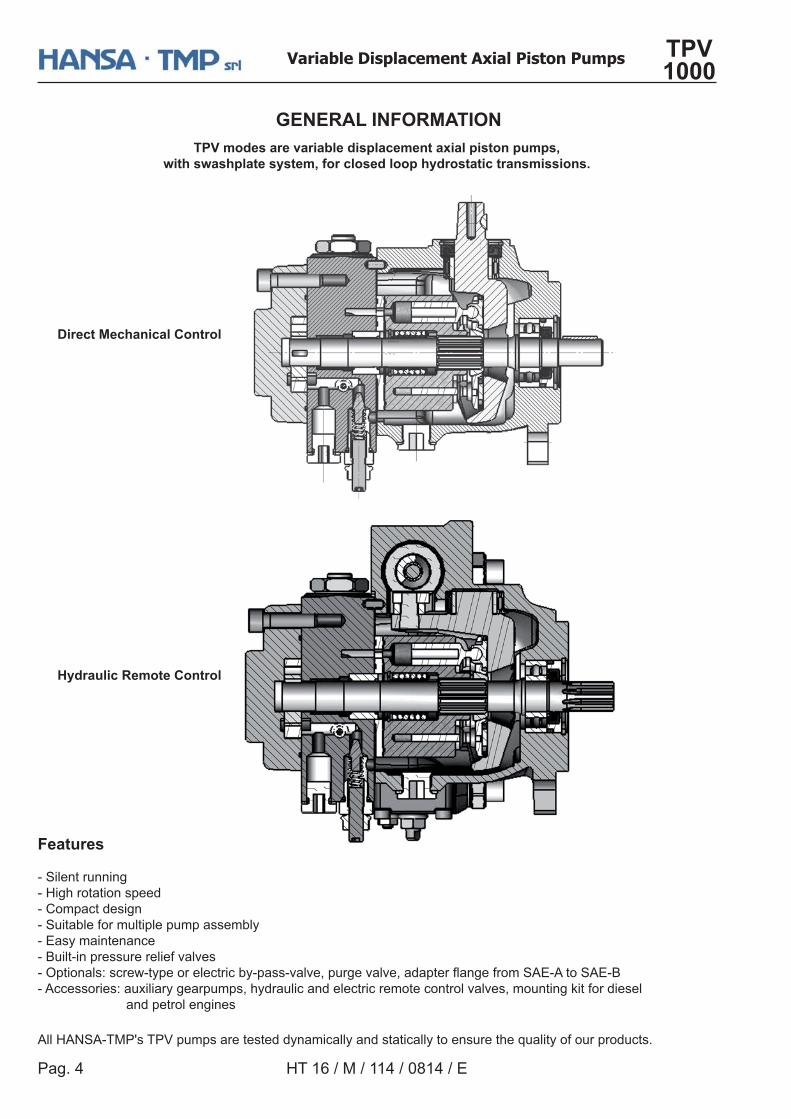
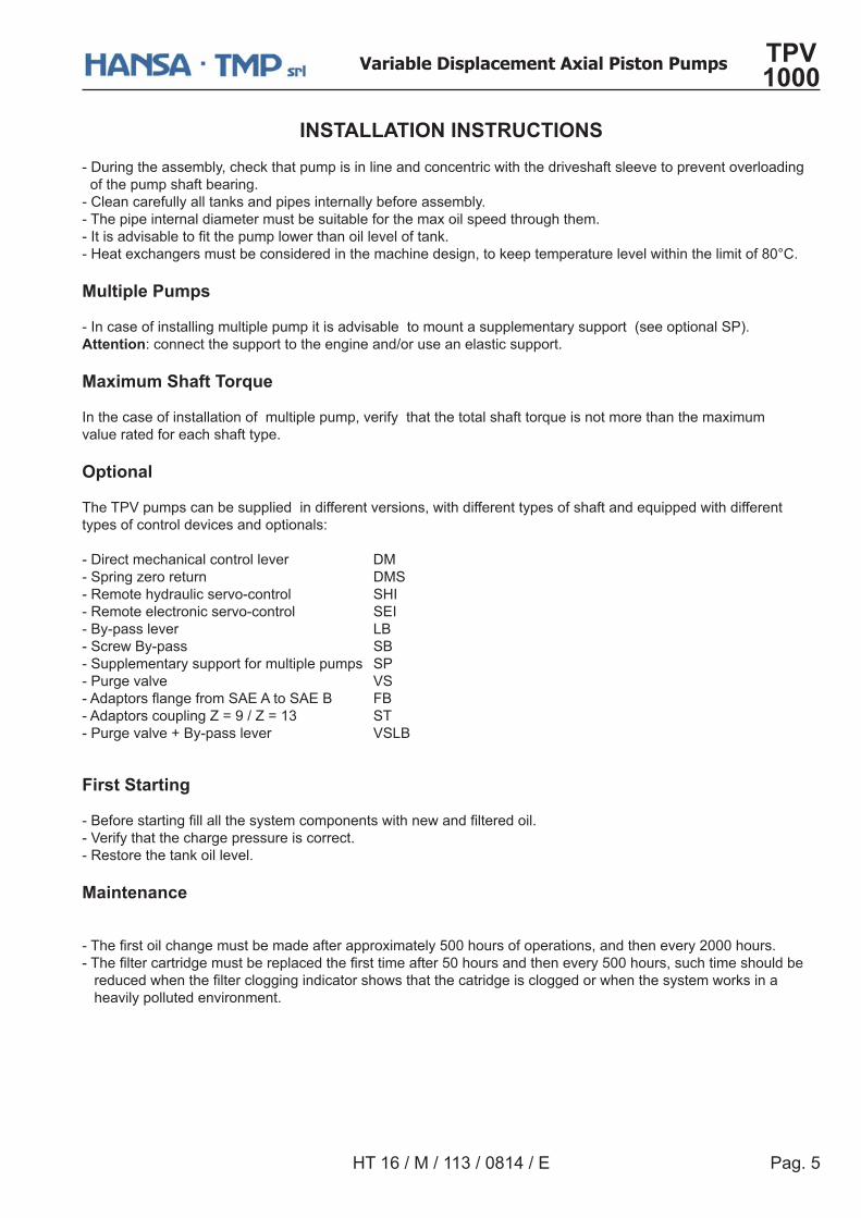
GENERAL INFORMATIONTPV modes are variable displacement axial piston pumps,
with swashplate system, for closed loop hydrostatic transmissions.
Direct Mechanical Control
Hydraulic Remote Control
Pag. 5
Variable Displacement Axial Piston Pumps TPV 1000
HT 16 / M / 113 / 0814 / E
INSTALLATION INSTRUCTIONS- During the assembly, check that pump is in line and concentric with the driveshaft sleeve to prevent overloading of the pump shaft bearing.- Clean carefully all tanks and pipes internally before assembly.- The pipe internal diameter must be suitable for the max oil speed through them.�$������������� ��������������������������%&- Heat exchangers must be considered in the machine design, to keep temperature level within the limit of 80°C.
Multiple Pumps
- In case of installing multiple pump it is advisable to mount a supplementary support (see optional SP).Attention: connect the support to the engine and/or use an elastic support.
Maximum Shaft Torque
In the case of installation of multiple pump, verify that the total shaft torque is not more than the maximum value rated for each shaft type.
Optional
The TPV pumps can be supplied in different versions, with different types of shaft and equipped with differenttypes of control devices and optionals:
- Direct mechanical control lever DM- Spring zero return DMS- Remote hydraulic servo-control SHI- Remote electronic servo-control SEI- By-pass lever LB- Screw By-pass SB- Supplementary support for multiple pumps SP- Purge valve VS�!�����������������!"!���!"# *#- Adaptors coupling Z = 9 / Z = 13 ST- Purge valve + By-pass lever VSLB
First Starting �#������������� ������������������������������ �������&- Verify that the charge pressure is correct.- Restore the tank oil level.
Maintenance ���� �������������������������������;������<>>������������������������������?>>>�����&���� ���������������������������� ������������<>�����������������<>>����������������������������������� �����������������������������������������������������������������%���� heavily polluted environment.
Pag. 6
Variable Displacement Axial Piston Pumps TPV 1000
HT 16 / M / 114 / 0814 / E
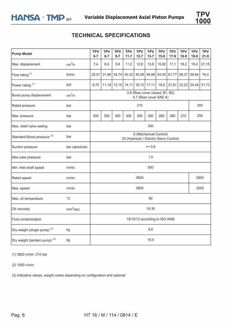
TECHNICAL SPECIFICATIONS
TPV6-7
TPV8-7
TPV9-7
TPV11-7
TPV12-7
TPV13-7
TPV15-9
TPV17-9
TPV18-9
TPV19-9
TPV21-9
Max. displacement cm3/n 7,4 8,9 9,6 11,2 12,8 13,6 15,00 17,1 18,2 19,4 21,15
Flow rating (1) lt/min. 25,01 31,96 34,74 40,32 46,08 48,88 54,00 61,77 66,37 69,84 76,4
Power rating (1) kW 8,75 11,18 12,15 14,11 16,12 17,11 18,9 21,61 23,23 24,44 31,73
Boost pump displacement cm3/n
Rated pressure bar
Max. pressure bar 300 300 300 300 300 300 280 280 270
Max. relief valve setting bar
Standard Boost pressure (2) bar
Suction pressure bar (absolute)
Max.case pressure bar
Min. inlet shaft speed n/min.
Rated speed n/min.
Max. speed n/min.
Max. oil temperature °C
Oil viscosity mm2/sec.
Fluid contamination
Dry weight (single pump) (3) kg
Dry weight (tandem pump) (3) kg
(2) 1000 n/min.
(3) Indicative values, weight varies depending on configuration and optional
19,5
3,9 (Rear cover closed, B1, B2)4,7 (Rear cover SAE A)
80
15-35
18/15/12 according to ISO 4406
8,8
3200
300
6 (Mechanical Control)20 (Hydraulic / Electric Servo Control)
>= 0,8
1,5
500
Pump Model
210 200
250
3600
(1) 3600 n/min. 210 bar
3900
2900
Pag. 7
Variable Displacement Axial Piston Pumps TPV 1000
HT 16 / M / 113 / 0814 / E
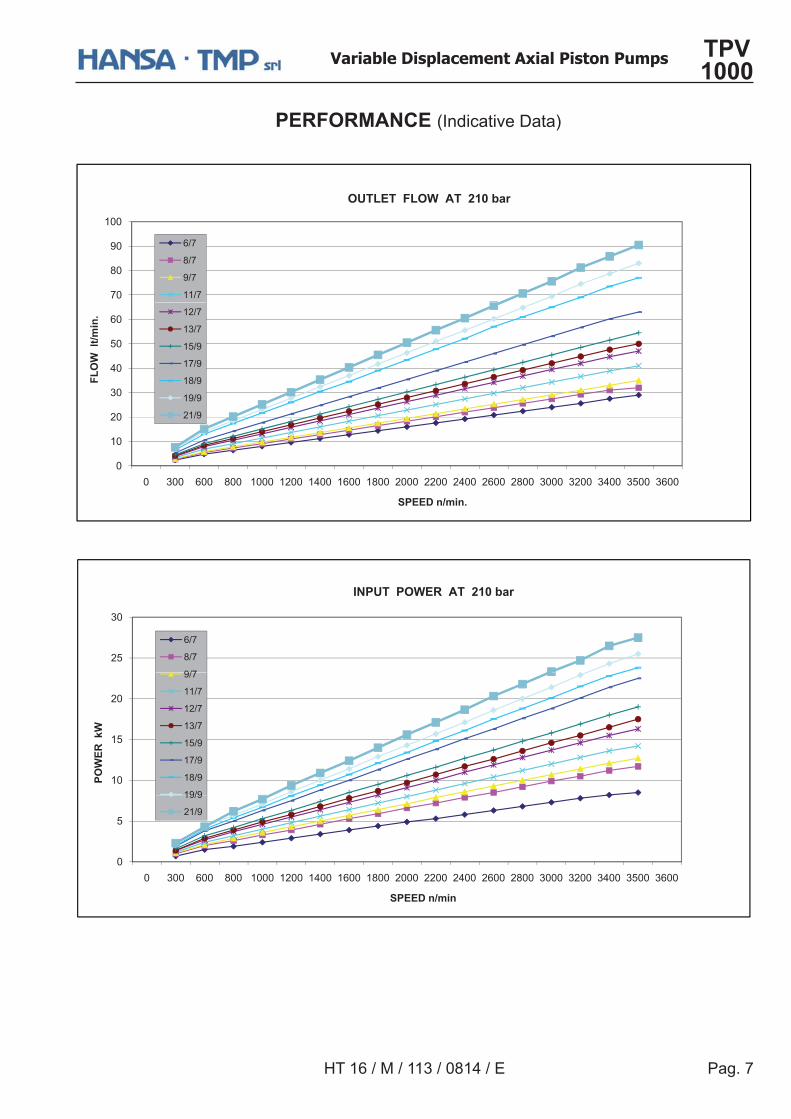
PERFORMANCE (Indicative Data)
J>
K>
Q>
U>>
OUTLET FLOW AT 210 bar
XYJ
KYJ
QYJ
UUYJ
?>
[>
\>
<>
X>
FLO
W l
t/min
. U?YJ
U[YJ
U<YQ
UJYQ
UKYQ
UQYQ
?UYQ
>
U>
> [>> X>> K>> U>>> U?>> U\>> UX>> UK>> ?>>> ??>> ?\>> ?X>> ?K>> [>>> [?>> [\>> [<>> [X>>
SPEED n/min.
?<
[>
INPUT POWER AT 210 bar
XYJ
KYJ
QYJ
U>
U<
?>
POW
ER k
W
QYJ
UUYJ
U?YJ
U[YJ
U<YQ
UJYQ
UKYQ
UQYQ
>
<
> [>> X>> K>> U>>> U?>> U\>> UX>> UK>> ?>>> ??>> ?\>> ?X>> ?K>> [>>> [?>> [\>> [<>> [X>>
SPEED n/min
UQYQ
?UYQ
Pag. 8
Variable Displacement Axial Piston Pumps TPV 1000
HT 16 / M / 114 / 0814 / E
See shaft and�����������
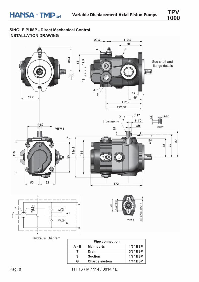
A - B Main ports 1/2" BSPT Drain 3/8" BSPS Suction 1/2" BSPG Charge system 1/4" BSP
Pipe connection
SINGLE PUMP - Direct Mechanical ControlINSTALLATION DRAWING
Hydraulic Diagram
Pag. 9
Variable Displacement Axial Piston Pumps TPV 1000
HT 16 / M / 113 / 0814 / E
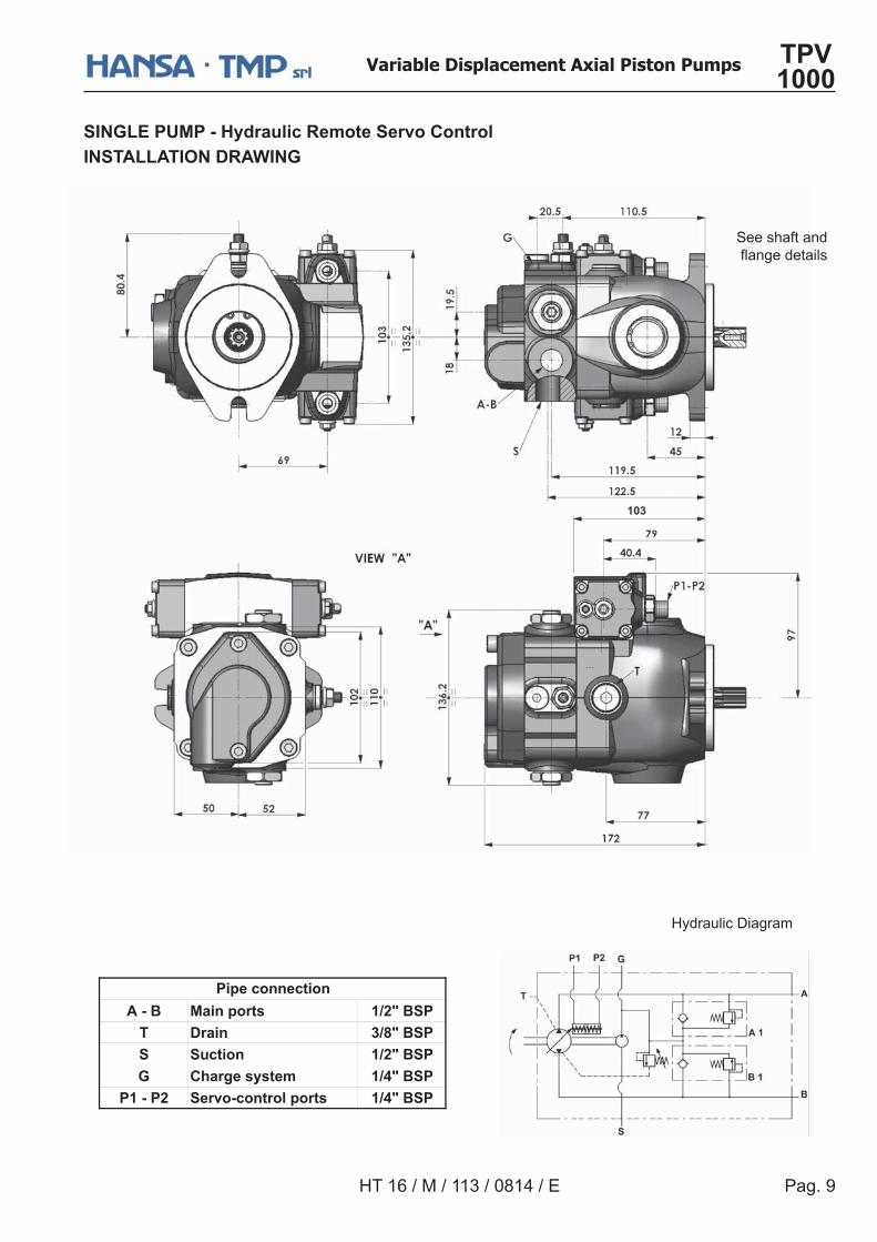
A - B Main ports 1/2" BSPT Drain 3/8" BSPS Suction 1/2" BSPG Charge system 1/4" BSP
P1 - P2 Servo-control ports 1/4" BSP
Pipe connection
See shaft and�����������
SINGLE PUMP - Hydraulic Remote Servo ControlINSTALLATION DRAWING
Hydraulic Diagram
Pag. 10
Variable Displacement Axial Piston Pumps TPV 1000
HT 16 / M / 114 / 0814 / E
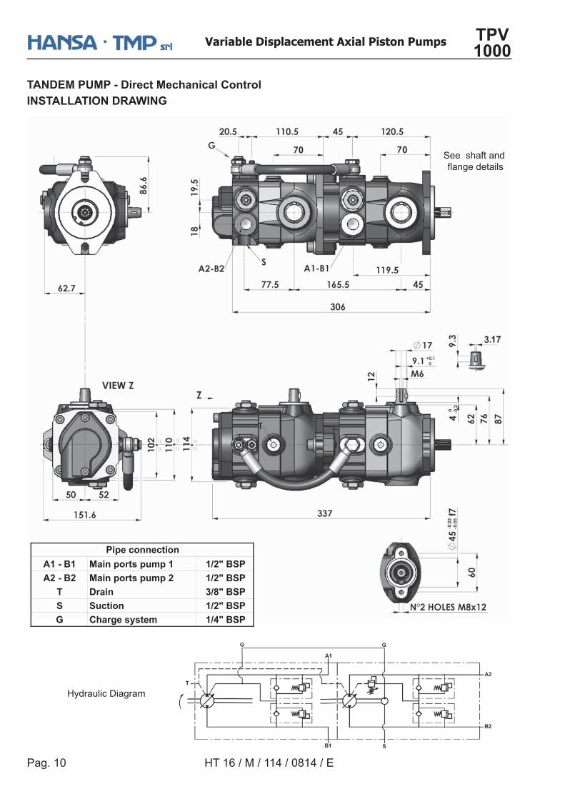
A1 - B1 Main ports pump 1 1/2" BSPA2 - B2 Main ports pump 2 1/2" BSP
T Drain 3/8" BSPS Suction 1/2" BSPG Charge system 1/4" BSP
Pipe connection
See shaft and�����������
TANDEM PUMP - Direct Mechanical ControlINSTALLATION DRAWING
Hydraulic Diagram
Pag. 11
Variable Displacement Axial Piston Pumps TPV 1000
HT 16 / M / 113 / 0814 / E
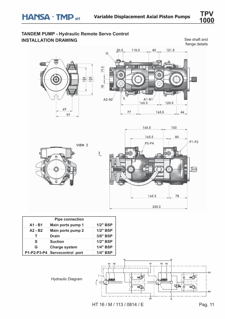
TANDEM PUMP - Hydraulic Remote Servo ControlINSTALLATION DRAWING
A1 - B1 Main ports pump 1 1/2" BSPA2 - B2 Main ports pump 2 1/2" BSP
T Drain 3/8" BSPS Suction 1/2" BSPG Charge system 1/4" BSP
P1-P2-P3-P4 Servocontrol port 1/4" BSP
Pipe connection
See shaft and�����������
Hydraulic Diagram
Pag. 12
Variable Displacement Axial Piston Pumps TPV 1000
HT 16 / M / 114 / 0814 / E
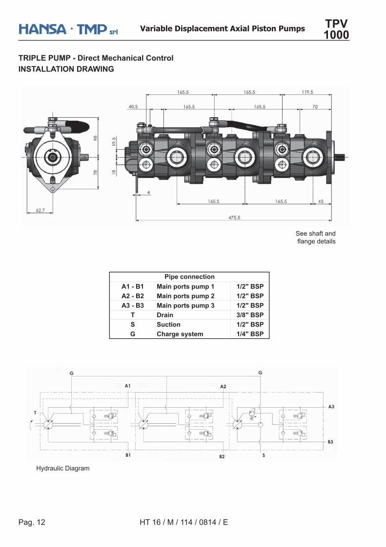
TRIPLE PUMP - Direct Mechanical ControlINSTALLATION DRAWING
See shaft and�����������
A1 - B1 Main ports pump 1 1/2" BSPA2 - B2 Main ports pump 2 1/2" BSPA3 - B3 Main ports pump 3 1/2" BSP
T Drain 3/8" BSPS Suction 1/2" BSPG Charge system 1/4" BSP
Pipe connection
Hydraulic Diagram
Pag. 13
Variable Displacement Axial Piston Pumps TPV 1000
HT 16 / M / 113 / 0814 / E
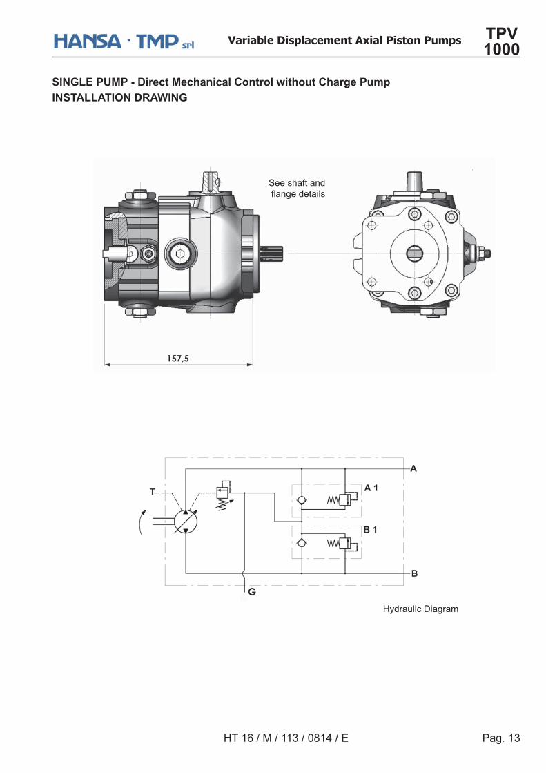
SINGLE PUMP - Direct Mechanical Control without Charge PumpINSTALLATION DRAWING
See shaft and�����������
Hydraulic Diagram
Pag. 14
Variable Displacement Axial Piston Pumps TPV 1000
HT 16 / M / 114 / 0814 / E
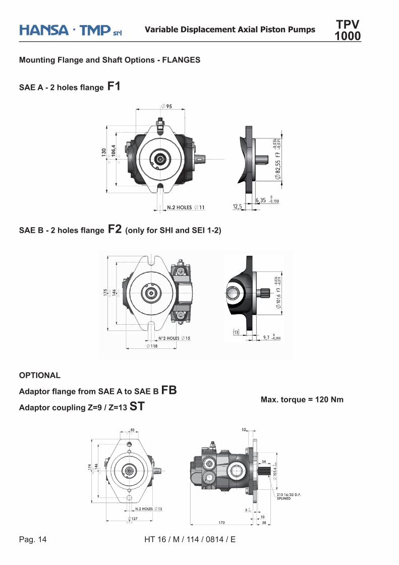
Mounting Flange and Shaft Options - FLANGES
�������������� ���� F1
OPTIONAL
������� �������������������������Adaptor coupling Z=9 / Z=13 ST
�������������� ���� F2 (only for SHI and SEI 1-2)
Max. torque = 120 Nm
Pag. 15
Variable Displacement Axial Piston Pumps TPV 1000
HT 16 / M / 113 / 0814 / E
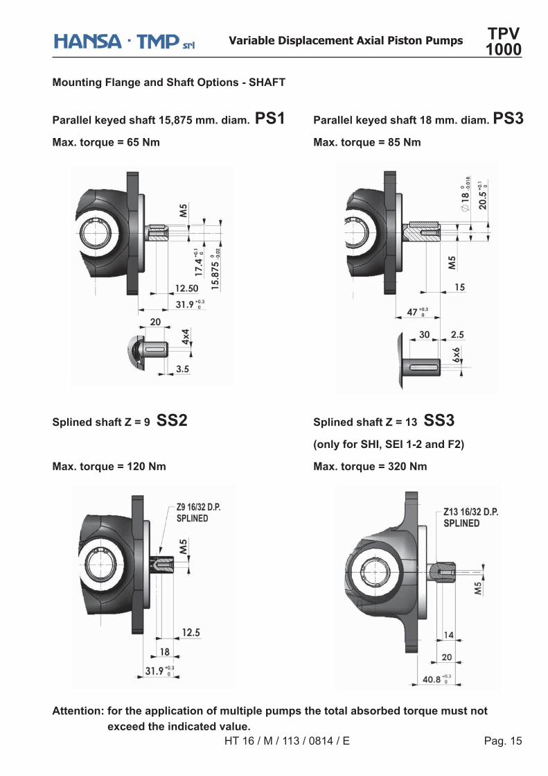
Splined shaft Z = 9 SS2 Splined shaft Z = 13 SS3 (only for SHI, SEI 1-2 and F2)
Max. torque = 120 Nm Max. torque = 320 Nm
Mounting Flange and Shaft Options - SHAFT
Parallel keyed shaft 15,875 mm. diam. PS1 Parallel keyed shaft 18 mm. diam. PS3Max. torque = 65 Nm Max. torque = 85 Nm
Attention: for the application of multiple pumps the total absorbed torque must not exceed the indicated value.
Pag. 16
Variable Displacement Axial Piston Pumps TPV 1000
HT 16 / M / 114 / 0814 / E
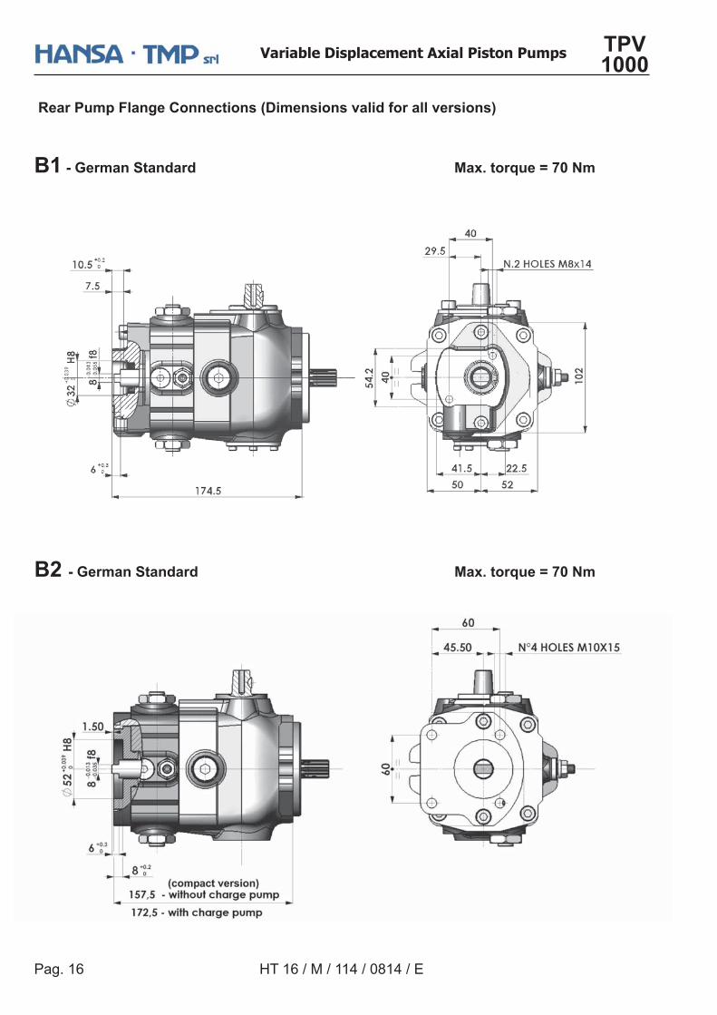
���- German Standard Max. torque = 70 Nm
Rear Pump Flange Connections (Dimensions valid for all versions)
�� - German Standard Max. torque = 70 Nm
Pag. 17
Variable Displacement Axial Piston Pumps TPV 1000
HT 16 / M / 113 / 0814 / E
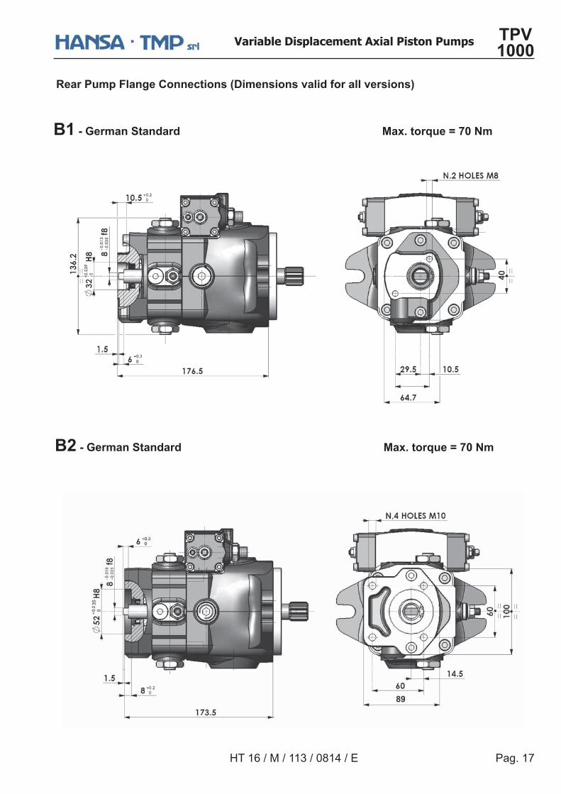
Rear Pump Flange Connections (Dimensions valid for all versions)
�� - German Standard Max. torque = 70 Nm
�� - German Standard Max. torque = 70 Nm
Pag. 18
Variable Displacement Axial Piston Pumps TPV 1000
HT 16 / M / 114 / 0814 / E
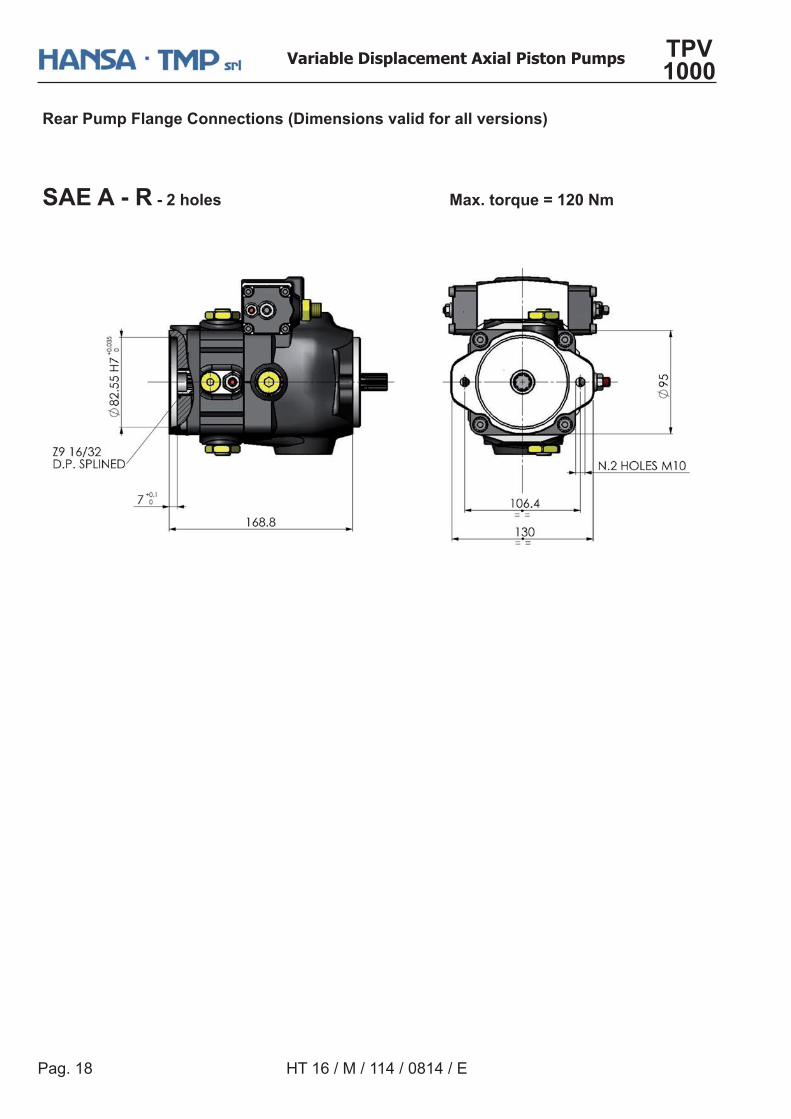
Rear Pump Flange Connections (Dimensions valid for all versions)
SAE A - R - 2 holes Max. torque = 120 Nm
Pag. 19
Variable Displacement Axial Piston Pumps TPV 1000
HT 16 / M / 113 / 0814 / E
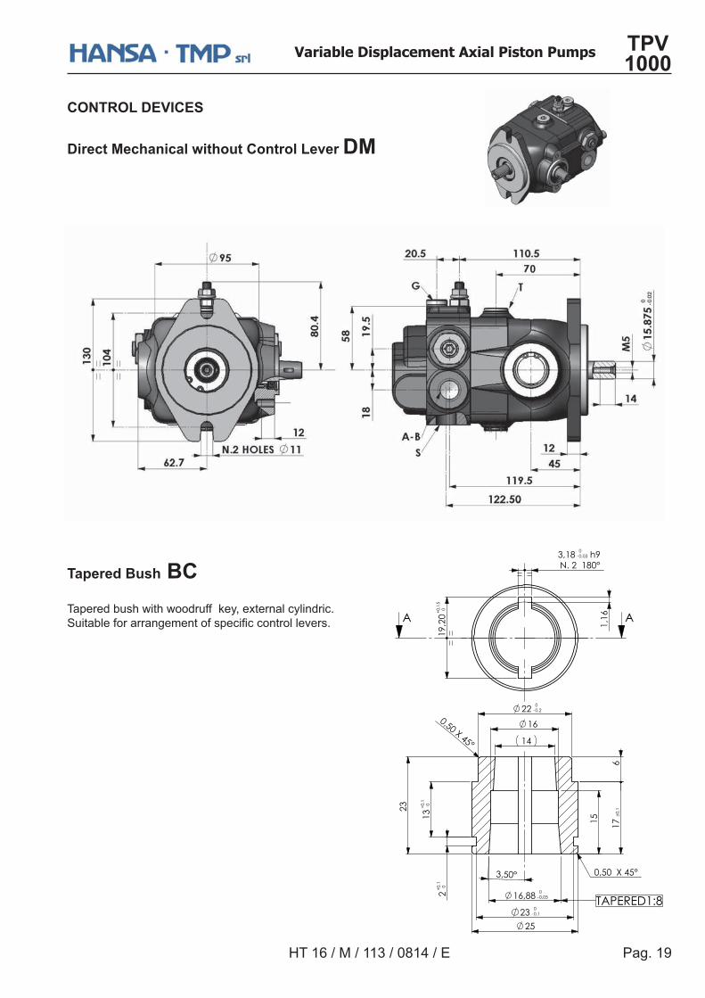
CONTROL DEVICES
Direct Mechanical without Control Lever DM
���������������
Tapered bush with woodruff key, external cylindric.���������������������������� ������������&
����
����
���
�� ����� � �
���������
����� �
�� �����
� �����
�������
�
��� ������
� ��
����
��
��
�������
���
��
���� �������
��
����
��
������
���������
Pag. 20
Variable Displacement Axial Piston Pumps TPV 1000
HT 16 / M / 114 / 0814 / E
CONTROL DEVICES
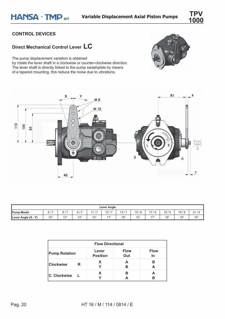
Direct Mechanical Control Lever LCThe pump displacement variation is obtainedby rotate the lever shaft in a clockwise or counter-clockwise direction.The lever shaft is directly linked to the pump swashplate by meansof a tapered mounting, this reduce the noise due to vibrations.
Pump Rotation Lever Position
Flow Out
Flow In
Clockwise RX Y
A �
� A
C. Clockwise LX Y
� A
A �
Flow Directional
Pump Model 6 / 7 8 / 7 9 / 7 11 / 7 12 / 7 13 / 7 15 / 9 17 / 9 18 / 9 19 / 9 21 / 9
Lever Angle (X - Y) 10° 12° 13° 15° 17° 18° 15° 17° 18° 19° 19°
Lever Angle
Pag. 21
Variable Displacement Axial Piston Pumps TPV 1000
HT 16 / M / 113 / 0814 / E
CONTROL DEVICES
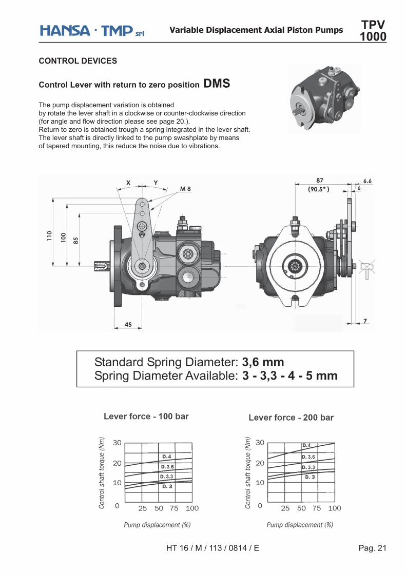
Control Lever with return to zero position DMSThe pump displacement variation is obtainedby rotate the lever shaft in a clockwise or counter-clockwise direction]����������������������������������?>&^&Return to zero is obtained trough a spring integrated in the lever shaft.The lever shaft is directly linked to the pump swashplate by meansof tapered mounting, this reduce the noise due to vibrations.
Pag. 22
Variable Displacement Axial Piston Pumps TPV 1000
HT 16 / M / 114 / 0814 / E
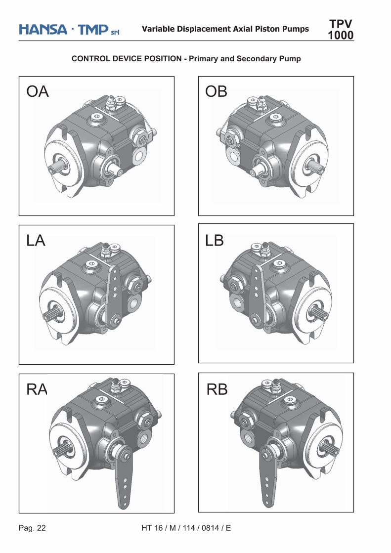
CONTROL DEVICE POSITION - Primary and Secondary Pump
OA
LA
RA
OB
LB
RB
Pag. 23
Variable Displacement Axial Piston Pumps TPV 1000
HT 16 / M / 113 / 0814 / E
CONTROL DEVICES
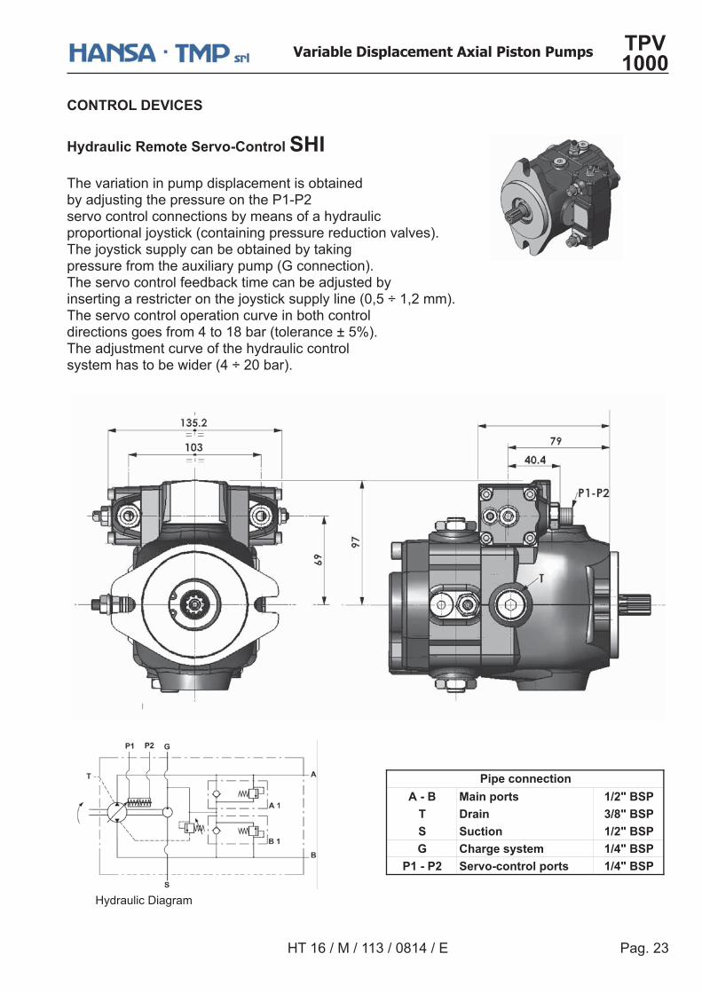
Hydraulic Remote Servo-Control SHIThe variation in pump displacement is obtained by adjusting the pressure on the P1-P2 servo control connections by means of a hydraulic proportional joystick (containing pressure reduction valves).The joystick supply can be obtained by taking pressure from the auxiliary pump (G connection).The servo control feedback time can be adjusted by inserting a restricter on the joystick supply line (0,5 ÷ 1,2 mm).The servo control operation curve in both control directions goes from 4 to 18 bar (tolerance ± 5%). The adjustment curve of the hydraulic control system has to be wider (4 ÷ 20 bar).
A - B Main ports 1/2" BSPT Drain 3/8" BSPS Suction 1/2" BSPG Charge system 1/4" BSP
P1 - P2 Servo-control ports 1/4" BSP
Pipe connection
Hydraulic Diagram
Pag. 24
Variable Displacement Axial Piston Pumps TPV 1000
HT 16 / M / 114 / 0814 / E
CONTROL DEVICES
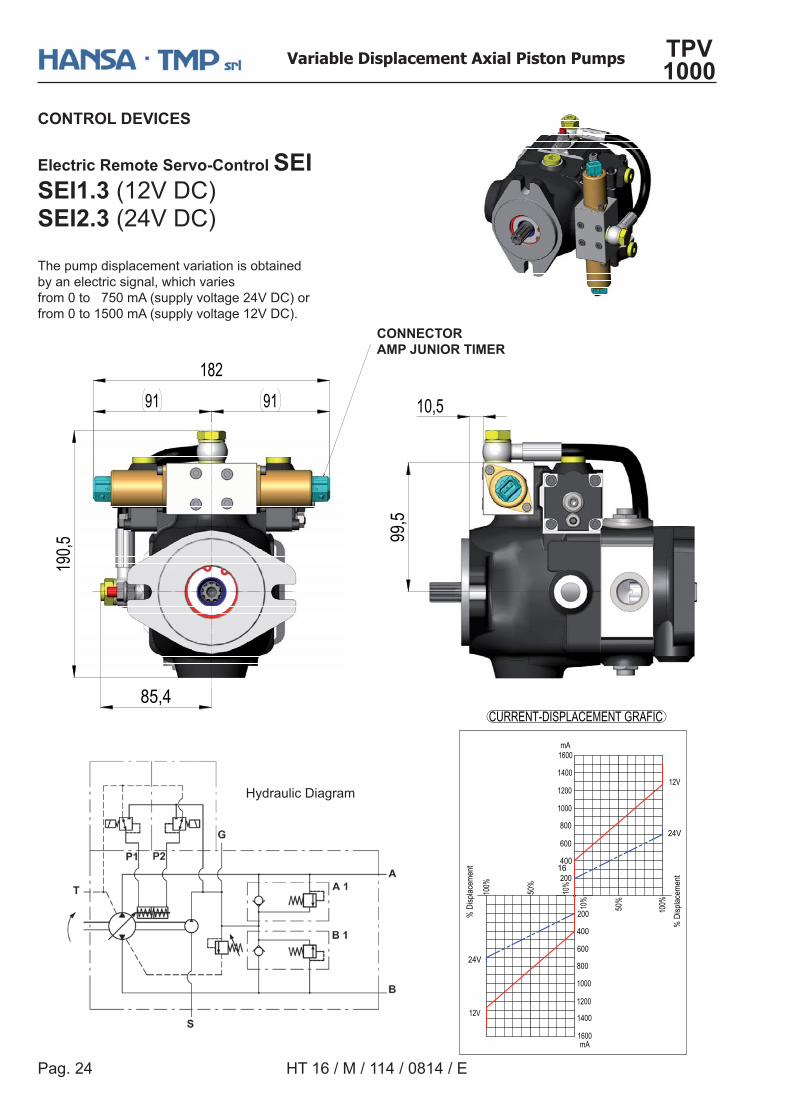
Electric Remote Servo-Control SEISEI1.3 (12V DC)SEI2.3 (24V DC) The pump displacement variation is obtainedby an electric signal, which variesfrom 0 to 750 mA (supply voltage 24V DC) orfrom 0 to 1500 mA (supply voltage 12V DC).
Hydraulic Diagram
CONNECTORAMP JUNIOR TIMER
Pag. 25
Variable Displacement Axial Piston Pumps TPV 1000
HT 16 / M / 113 / 0814 / E
OPTIONAL
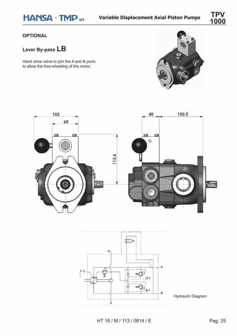
����������������
Hand drive valve to join the A and B portsto allow the free-wheeling of the motor.
Hydraulic Diagram
Pag. 26
Variable Displacement Axial Piston Pumps TPV 1000
HT 16 / M / 114 / 0814 / E
OPTIONAL
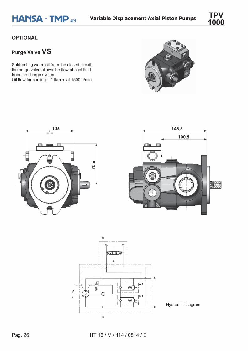
Purge Valve VSSubtracting warm oil from the closed circuit,�������������������������������from the charge system.��������������`U�Y���&��U<>>�Y���&
Hydraulic Diagram
Pag. 27
Variable Displacement Axial Piston Pumps TPV 1000
HT 16 / M / 113 / 0814 / E
OPTIONAL
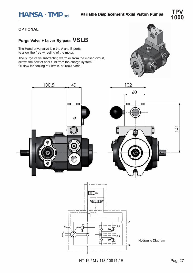
!�����#����$���������������#���The Hand drive valve join the A and B portsto allow the free-wheeling of the motor.
The purge valve,subtracting warm oil from the closed circuit,��������������������������������������&��������������`U�Y���&��U<>>�Y���&
Hydraulic Diagram
Pag. 28
Variable Displacement Axial Piston Pumps TPV 1000
HT 16 / M / 114 / 0814 / E
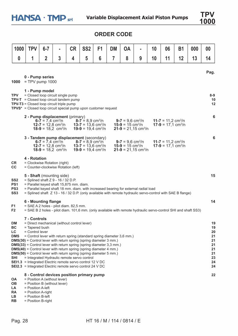
ORDER CODE
Pag. 0 - Pump series1000 = TPV pump 1000
1 - Pump modelTPV = Closed loop circuit single pump 8-9TPV-T = Closed loop circuit tandem pump 10TPV-T3 = Closed loop circuit triple pump 12TPVS* = Closed loop circuit special pump upon customer request
2 - Pump displacement (primary) 6 6-7 = 7,4 cm3/n 8-7 = 8,9 cm3/n 9-7 = 9,6 cm3/n 11-7 = 11,2 cm3/n 12-7 = 12,8 cm3/n 13-7 = 13,6 cm3/n 15-9 = 15 cm3/n 17-9 = 17,1 cm3/n 18-9 = 18,2 cm3/n 19-9 = 19,4 cm3/n 21-9 = 21,15 cm3/n
3 - Tandem pump displacement (secondary) 6 6-7 = 7,4 cm3/n 8-7 = 8,9 cm3/n 9-7 = 9,6 cm3/n 11-7 = 11,2 cm3/n 12-7 = 12,8 cm3/n 13-7 = 13,6 cm3/n 15-9 = 15 cm3/n 17-9 = 17,1 cm3/n 18-9 = 18,2 cm3/n 19-9 = 19,4 cm3/n 21-9 = 21,15 cm3/n
4 - Rotation CR = Clockwise Rotation (right) CC = Counter-clockwise Rotation (left)
5 - Shaft (mounting side) 15SS2 = Splined shaft Z 9 - 16 / 32 D.P. PS1 = Parallel keyed shaft 15,875 mm. diam.PS3 = Parallel keyed shaft 18 mm. diam. with increased bearing for external radial loadSS3 `�����������{U[�UXY[?|&}&]���������������������������������������������!"#�����^
� %���&���'��� ����� � � � � � � � � � ������������(F1 = SAE A 2 holes - pilot diam. 82,5 mm.F2 = SAE B 2 holes - pilot diam. 101,6 mm. (only available with remote hydraulic servo-control SHI and shaft SS3)
7 - ControlsDM = Direct mechanical (without control lever) 19��� = Tapered bush 19LC = Control lever 20DMS = Control lever with return spring (standard spring diameter 3,6 mm.) 21DMS(30) = Control lever with return spring (spring diameter 3 mm.) 21DMS(33) = Control lever with return spring (spring diameter 3,3 mm.) 21DMS(40) = Control lever with return spring (spring diameter 4 mm.) 21DMS(50) = Control lever with return spring (spring diameter 5 mm.) 21SHI = Integrated Hydraulic remote servo control 23SEI1.3 = Integrated Electric remote servo control 12 V DC 24SEI2.3 = Integrated Electric remote servo control 24 V DC 24
8 - Control devices position primary pump 22OA = Position A (without lever))� = Position B (without lever)LA = Position A-leftRA = Position A-right�� = Position B-left*� = Position B-right
�+++ �!# %�, � �* ��� �� .& )� � �+ +% �� +++ ++
0 1 2 3 4 5 6 7 8 9 10 11 12 13 14
Pag. 29
Variable Displacement Axial Piston Pumps TPV 1000
HT 16 / M / 113 / 0814 / E
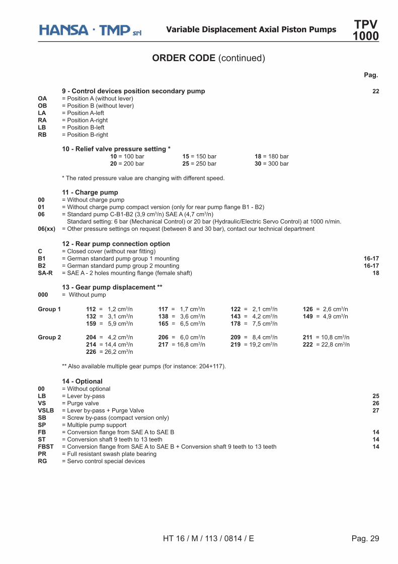
ORDER CODE (continued) Pag.
9 - Control devices position secondary pump 22OA = Position A (without lever))� = Position B (without lever)LA = Position A-leftRA = Position A-right�� = Position B-left*� = Position B-right
10 - Relief valve pressure setting * 10 = 100 bar 15 = 150 bar 18 = 180 bar 20 = 200 bar 25 = 250 bar 30 = 300 bar
* The rated pressure value are changing with different speed.
11 - Charge pump 00 = Without charge pump01 `�������������������������������]�������������������#U�#?^06 = Standard pump C-B1-B2 (3,9 cm3/n) SAE A (4,7 cm3/n) Standard setting: 6 bar (Mechanical Control) or 20 bar (Hydraulic/Electric Servo Control) at 1000 n/min.06(xx) = Other pressure settings on request (between 8 and 30 bar), contact our technical department 12 - Rear pump connection optionC `����������]����������� �����^��� = German standard pump group 1 mounting 16-17�� = German standard pump group 2 mounting 16-17SA-R `�!"!�?�����������������]����������^ 18
13 - Gear pump displacement **000 = Without pump
Group 1 112 = 1,2 cm3/n 117 = 1,7 cm3/n 122 = 2,1 cm3/n 126 = 2,6 cm3/n 132 = 3,1 cm3/n 138 = 3,6 cm3/n 143 = 4,2 cm3/n 149 = 4,9 cm3/n 159 = 5,9 cm3/n 165 = 6,5 cm3/n 178 = 7,5 cm3/n
Group 2 204 = 4,2 cm3/n 206 = 6,0 cm3/n 209 = 8,4 cm3/n 211 = 10,8 cm3/n 214 = 14,4 cm3/n 217 = 16,8 cm3/n 219 = 19,2 cm3/n 222 = 22,8 cm3/n 226 = 26,2 cm3/n
** Also available multiple gear pumps (for instance: 204+117).
14 - Optional00 = Without optional��� = Lever by-pass 25VS = Purge valve 26#���� = Lever by-pass + Purge Valve 27 ��� = Screw by-pass (compact version only) SP = Multiple pump support ��� `��������������������!"!���!"# 14ST = Conversion shaft 9 teeth to 13 teeth 14���� `��������������������!"!���!"#����������������Q�������U[����� 14PR = Full resistant swash plate bearingRG = Servo control special devices
Pag. 30
Variable Displacement Axial Piston Pumps TPV 1000
HT 16 / M / 114 / 0814 / E
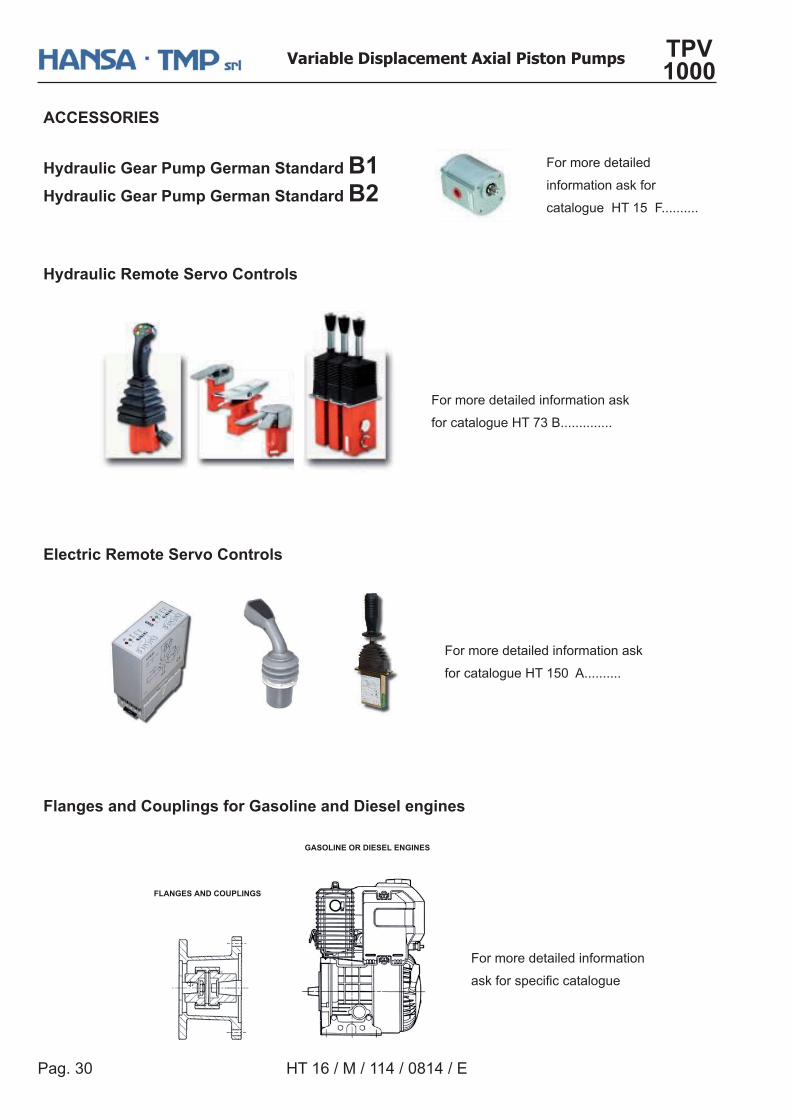
Hydraulic Remote Servo Controls
For more detailed information
��%�������� ���������
Flanges and Couplings for Gasoline and Diesel engines
FLANGES AND COUPLINGS
GASOLINE OR DIESEL ENGINES
Electric Remote Servo Controls
For more detailed information ask
for catalogue HT 150 A..........
For more detailed information ask
for catalogue HT 73 B..............
ACCESSORIES
Hydraulic Gear Pump German Standard ��Hydraulic Gear Pump German Standard ��
For more detailed
information ask for
catalogue HT 15 F..........
As HANSA-TMP has a very extensive range of products and some products have a variety of applications, the information supplied may often only apply ��������������� ��
If the catalogue does not supply all the information required, please contact ����������� ��������������������������� ��������������������!��������������������������"��� "���������������������� �
Whilst every reasonable endeavour has been made to ensure accuracy, thispublication cannot be considered to represent part of any contract, whether �#������������������
���������������������"�����$������������� �������������������������$������������ ������$����� � ������������� ���$������������������������������"��������� "�������������� ���$������$$��� �����������!�� ���� ���������� ��!������"� "������ $������ �