Embed Size (px)
Citation preview
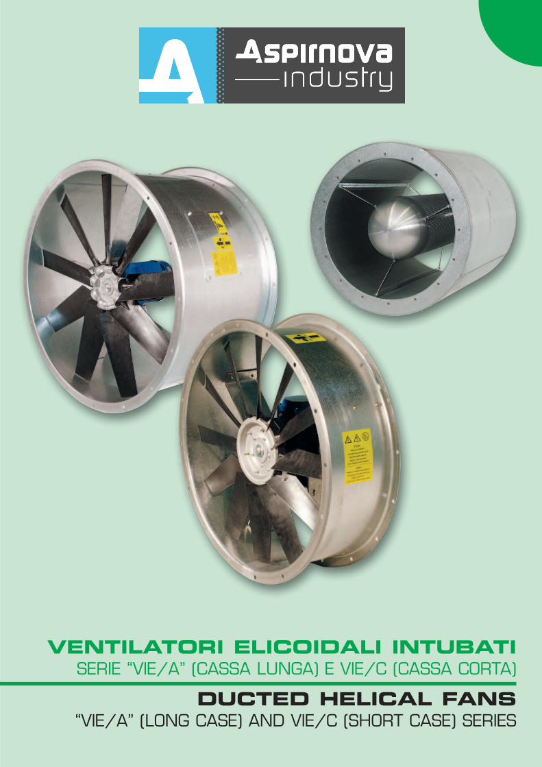
VENTILATORI ELICOIDALI INTUBATISERIE “VIE/A” (CASSA LUNGA) E VIE/C (CASSA CORTA)
DUCTED HELICAL FANS“VIE/A” (LONG CASE) AND VIE/C (SHORT CASE) SERIES
4
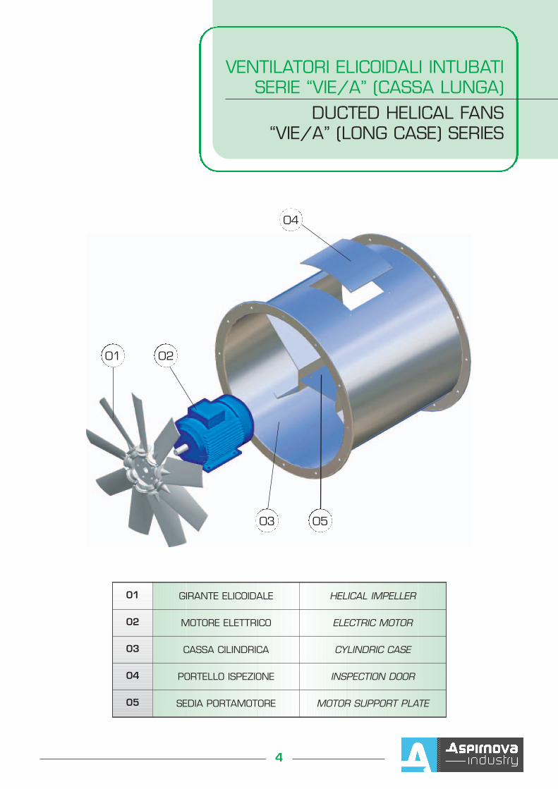
VENTILATORI ELICOIDALI INTUBATISERIE “VIE/A” (CASSA LUNGA)
DUCTED HELICAL FANS“VIE/A” (LONG CASE) SERIES
01 GIRANTE ELICOIDALE HELICAL IMPELLER
02 MOTORE ELETTRICO ELECTRIC MOTOR
03 CASSA CILINDRICA CYLINDRIC CASE
04 PORTELLO ISPEZIONE INSPECTION DOOR
05 SEDIA PORTAMOTORE MOTOR SUPPORT PLATE
01 02
04
03 05
6
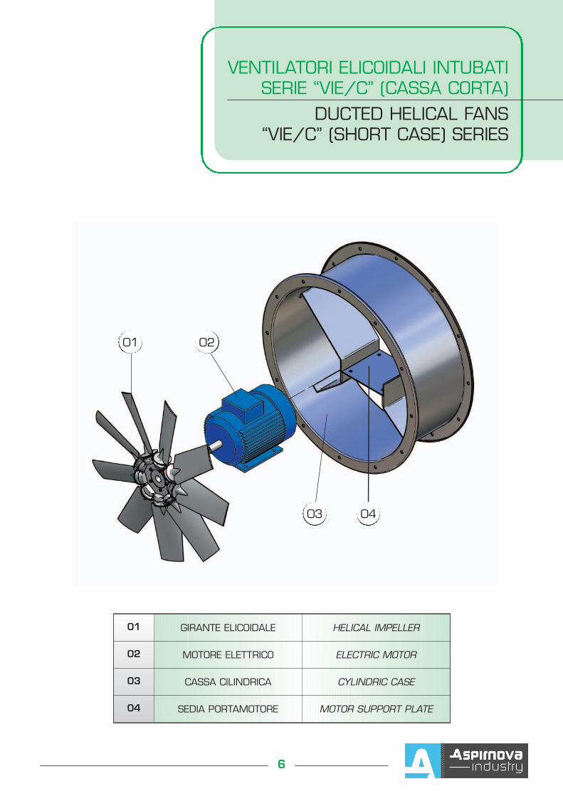
VENTILATORI ELICOIDALI INTUBATISERIE “VIE/C” (CASSA CORTA)
DUCTED HELICAL FANS“VIE/C” (SHORT CASE) SERIES
01 GIRANTE ELICOIDALE HELICAL IMPELLER
02 MOTORE ELETTRICO ELECTRIC MOTOR
03 CASSA CILINDRICA CYLINDRIC CASE
04 SEDIA PORTAMOTORE MOTOR SUPPORT PLATE
01 02
03 04
44
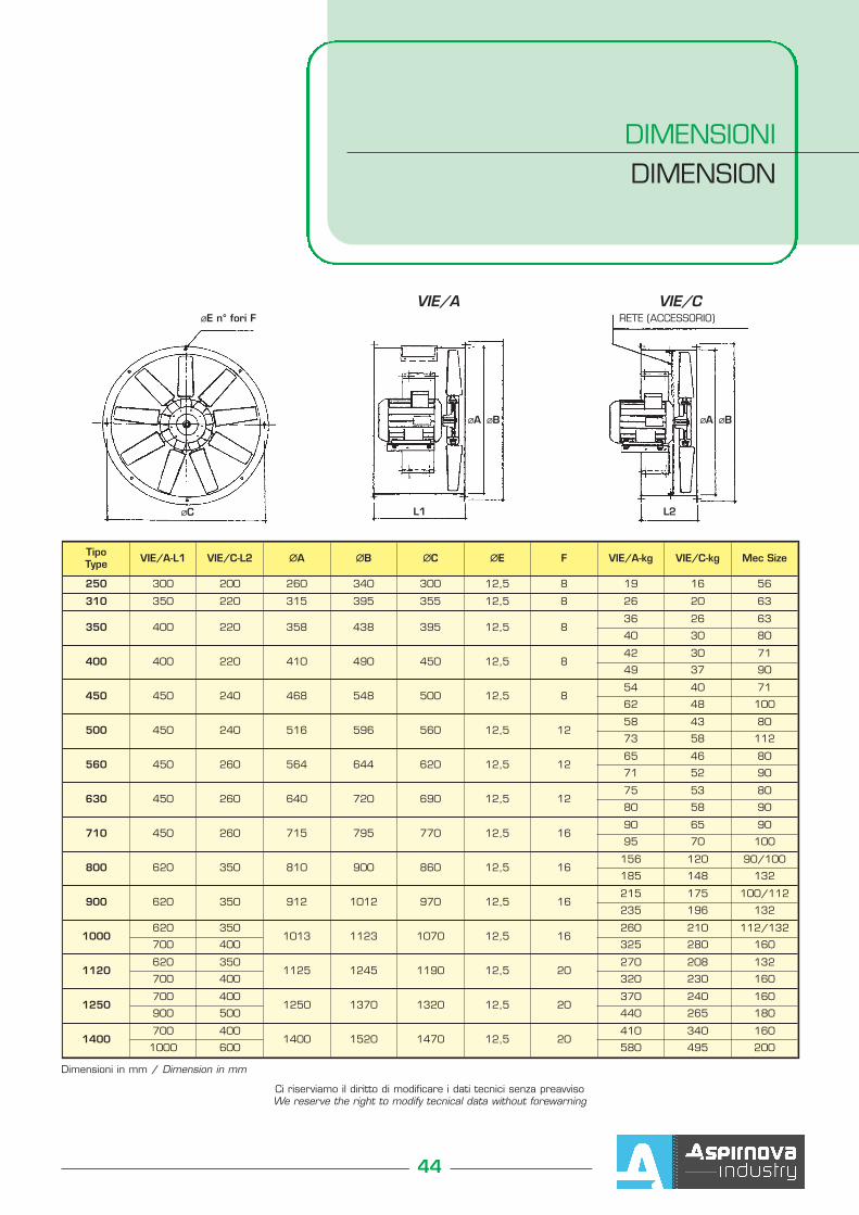
DIMENSIONIDIMENSION
Tipo Type VIE/A-L1 VIE/C-L2 ∅∅A ∅∅B ∅∅C ∅∅E F VIE/A-kg VIE/C-kg Mec Size
250 300 200 260 340 300 12,5 8 19 16 56
310 350 220 315 395 355 12,5 8 26 20 63
350 400 220 358 438 395 12,5 836 26 63
40 30 80
400 400 220 410 490 450 12,5 842 30 71
49 37 90
450 450 240 468 548 500 12,5 854 40 71
62 48 100
500 450 240 516 596 560 12,5 1258 43 80
73 58 112
560 450 260 564 644 620 12,5 1265 46 80
71 52 90
630 450 260 640 720 690 12,5 1275 53 80
80 58 90
710 450 260 715 795 770 12,5 1690 65 90
95 70 100
800 620 350 810 900 860 12,5 16156 120 90/100
185 148 132
900 620 350 912 1012 970 12,5 16215 175 100/112
235 196 132
1000620 350
1013 1123 1070 12,5 16260 210 112/132
700 400 325 280 160
1120620 350
1125 1245 1190 12,5 20270 208 132
700 400 320 230 160
1250700 400
1250 1370 1320 12,5 20370 240 160
900 500 440 265 180
1400700 400
1400 1520 1470 12,5 20410 340 160
1000 600 580 495 200
Ci riserviamo il diritto di modificare i dati tecnici senza preavvisoWe reserve the right to modify tecnical data without forewarning
Dimensioni in mm / Dimension in mm
∅∅E n° fori F
∅∅C L1 L2
∅∅A ∅∅B ∅∅A ∅∅B
RETE (ACCESSORIO)VIE/A VIE/C
P
Q
∅∅B
H
2 x ∅∅T R
S
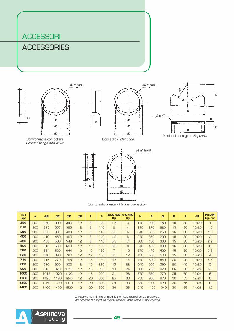
Boccaglio - Inlet cone
∅∅E n° fori F
∅∅B
∅∅C
∅∅D
ACCESSORIACCESSORIES
45
Tipo Type A ∅∅B ∅∅C ∅∅D ∅∅E F G BOCCAGLIO
KgGIUNTO
Kg H P Q R S ∅∅T PIEDINIKg/cad
250 200 260 300 340 12 8 140 1,5 3 170 200 150 15 30 10x20 1
310 200 315 355 395 12 8 140 2 4 210 270 220 15 30 10x20 1,5
350 200 358 395 438 12 8 140 3,5 5 240 320 250 15 30 10x20 1,8
400 200 410 450 490 12 8 140 4,2 6 270 350 290 15 30 10x20 2
450 200 468 500 548 12 8 140 5,3 7 300 400 330 15 30 10x20 2,2
500 200 516 560 596 12 12 180 6,5 8 340 430 380 15 30 10x20 3
560 200 564 620 644 12 12 180 7 10 370 470 420 15 30 10x20 3,5
630 200 640 690 720 12 12 180 8,3 12 430 550 500 15 30 10x20 4
710 200 715 770 795 12 16 180 12 14 470 600 540 20 40 10x20 4,5
800 200 810 860 900 12 16 220 15 22 540 650 590 20 40 10x20 5
900 200 912 970 1012 12 16 220 19 24 600 750 670 25 50 12x24 5,5
1000 200 1013 1070 1123 12 16 220 21 26 670 850 770 25 50 12x24 6
1120 200 1125 1190 1245 12 20 300 25 30 750 950 870 30 55 12x24 8
1250 200 1250 1320 1370 12 20 300 28 33 830 1000 920 30 55 12x24 9
1400 200 1400 1470 1520 12 20 300 34 38 940 1120 1040 30 55 14x26 12
Ci riserviamo il diritto di modificare i dati tecnici senza preavvisoWe reserve the right to modify tecnical data without forewarning
Controflangia con collareCounter flange with collar
80
∅∅E n° fori F
∅∅B
∅∅C
∅∅D
∅∅E n° fori F
∅∅B
∅∅C
∅∅D
A
Piedini di sostegno - Supports
Giunto antivibrante - Flexible connection
G
46
INSTALLAZIONE DEL VENTILATOREFAN INSTALLATION
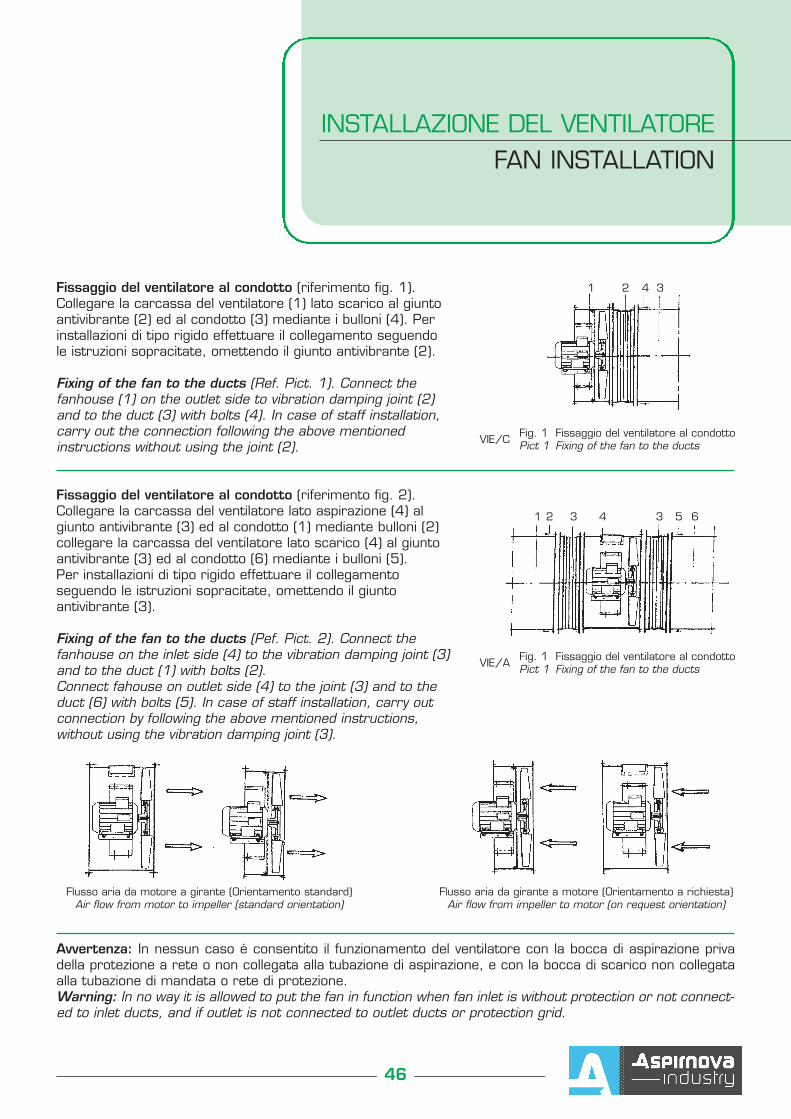
Fissaggio del ventilatore al condotto (riferimento fig. 1).Collegare la carcassa del ventilatore (1) lato scarico al giuntoantivibrante (2) ed al condotto (3) mediante i bulloni (4). Perinstallazioni di tipo rigido effettuare il collegamento seguendole istruzioni sopracitate, omettendo il giunto antivibrante (2).
Fixing of the fan to the ducts (Ref. Pict. 1). Connect thefanhouse (1) on the outlet side to vibration damping joint (2)and to the duct (3) with bolts (4). In case of staff installation,carry out the connection following the above mentionedinstructions without using the joint (2).
Fissaggio del ventilatore al condotto (riferimento fig. 2).Collegare la carcassa del ventilatore lato aspirazione (4) algiunto antivibrante (3) ed al condotto (1) mediante bulloni (2)collegare la carcassa del ventilatore lato scarico (4) al giuntoantivibrante (3) ed al condotto (6) mediante i bulloni (5). Per installazioni di tipo rigido effettuare il collegamentoseguendo le istruzioni sopracitate, omettendo il giuntoantivibrante (3).
Fixing of the fan to the ducts (Pef. Pict. 2). Connect thefanhouse on the inlet side (4) to the vibration damping joint (3)and to the duct (1) with bolts (2). Connect fahouse on outlet side (4) to the joint (3) and to theduct (6) with bolts (5). In case of staff installation, carry outconnection by following the above mentioned instructions,without using the vibration damping joint (3).
Avvertenza: In nessun caso é consentito il funzionamento del ventilatore con la bocca di aspirazione privadella protezione a rete o non collegata alla tubazione di aspirazione, e con la bocca di scarico non collegataalla tubazione di mandata o rete di protezione.Warning: In no way it is allowed to put the fan in function when fan inlet is without protection or not connect-ed to inlet ducts, and if outlet is not connected to outlet ducts or protection grid.
VIE/C Fig. 1 Fissaggio del ventilatore al condottoPict 1 Fixing of the fan to the ducts
VIE/A Fig. 1 Fissaggio del ventilatore al condottoPict 1 Fixing of the fan to the ducts
1 2 4 3
1 2 43 3 5 6
Flusso aria da motore a girante (Orientamento standard)Air flow from motor to impeller (standard orientation)
Flusso aria da girante a motore (Orientamento a richiesta)Air flow from impeller to motor (on request orientation)
48
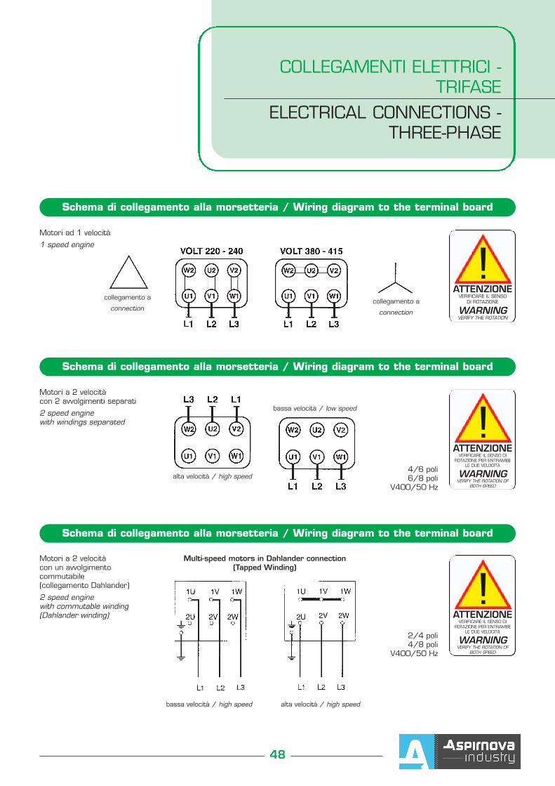
COLLEGAMENTI ELETTRICI -TRIFASE
ELECTRICAL CONNECTIONS - THREE-PHASE
Schema di collegamento alla morsetteria / Wiring diagram to the terminal board
Schema di collegamento alla morsetteria / Wiring diagram to the terminal board
Motori a 2 velocitàcon 2 avvolgimenti separati
2 speed enginewith windings separated
4/6 poli6/8 poli
V400/50 Hz
ATTENZIONEVERIFICARE IL SENSO
DI ROTAZIONE
WARNINGVERIFY THE ROTATION
collegamento a
connectioncollegamento a
connection
ATTENZIONEVERIFICARE IL SENSO DI
ROTAZIONE PER ENTRAMBE LE DUE VELOCITÀ
WARNINGVERIFY THE ROTATION OF
BOTH SPEED
alta velocità / high speed
bassa velocità / low speed
Motori ad 1 velocità
1 speed engine
Schema di collegamento alla morsetteria / Wiring diagram to the terminal board
Motori a 2 velocità con un avvolgimentocommutabile(collegamento Dahlander)
2 speed enginewith commutable winding(Dahlander winding)
2/4 poli4/8 poli
V400/50 Hz
ATTENZIONEVERIFICARE IL SENSO DI
ROTAZIONE PER ENTRAMBE LE DUE VELOCITÀ
WARNINGVERIFY THE ROTATION OF
BOTH SPEED
Multi-speed motors in Dahlander connection(Tapped Winding)
bassa velocità / high speed alta velocità / high speed
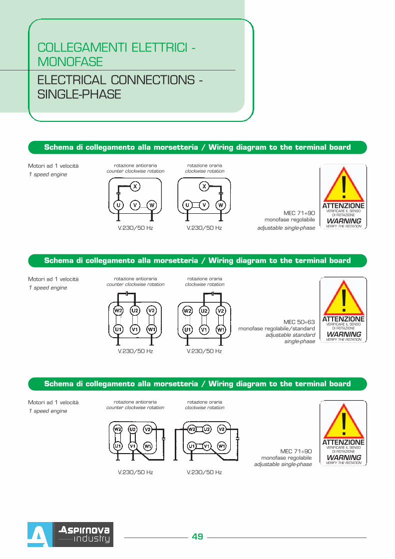
COLLEGAMENTI ELETTRICI -MONOFASEELECTRICAL CONNECTIONS -SINGLE-PHASE
49
Schema di collegamento alla morsetteria / Wiring diagram to the terminal board
Motori ad 1 velocità
1 speed engine
MEC 71÷90monofase regolabile
adjustable single-phaseV.230/50 Hz V.230/50 Hz
rotazione antiorariacounter clockwise rotation
rotazione orariaclockwise rotation
ATTENZIONEVERIFICARE IL SENSO
DI ROTAZIONE
WARNINGVERIFY THE ROTATION
Schema di collegamento alla morsetteria / Wiring diagram to the terminal board
Motori ad 1 velocità
1 speed engine
V.230/50 Hz V.230/50 Hz
rotazione antiorariacounter clockwise rotation
rotazione orariaclockwise rotation
ATTENZIONEVERIFICARE IL SENSO
DI ROTAZIONE
WARNINGVERIFY THE ROTATION
Schema di collegamento alla morsetteria / Wiring diagram to the terminal board
Motori ad 1 velocità
1 speed engine
MEC 71÷90monofase regolabile
adjustable single-phaseV.230/50 Hz V.230/50 Hz
rotazione antiorariacounter clockwise rotation
rotazione orariaclockwise rotation
ATTENZIONEVERIFICARE IL SENSO
DI ROTAZIONE
WARNINGVERIFY THE ROTATION
MEC 50÷63monofase regolabile/standard
adjustable standard single-phase
50
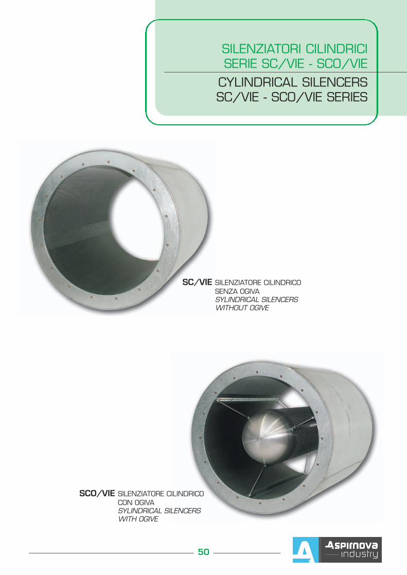
SILENZIATORI CILINDRICISERIE SC/VIE - SCO/VIE
CYLINDRICAL SILENCERSSC/VIE - SCO/VIE SERIES
SC/VIE SILENZIATORE CILINDRICO SENZA OGIVASYLINDRICAL SILENCERS WITHOUT OGIVE
SCO/VIE SILENZIATORE CILINDRICO CON OGIVASYLINDRICAL SILENCERS WITH OGIVE
SILENZIATORI CILINDRICI SERIE SC/VIE - SCO/VIECYLINDRICAL SILENCERSSC/VIE - SCO/VIE SERIES
51
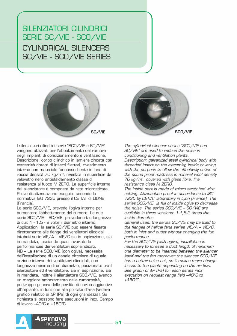
I silenziatori cilindrici serie “SCO/VIE e SC/VIE”vengono utilizzati per l’abbattimento del rumorenegli impianti di condizionamento e ventilazione.Descrizione: corpo cilindrico in lamiera zincata conestremità dotate di inserti filettati, rivestimentointerno con materiale fonoassorbente in lana diroccia densità 70 kg/m3, rivestita in superficie davelovetro nero antisfaldamento classe diresistenza al fuoco M ZERO. La superficie internadel silenziatore è composta da rete microstirata.Prove di attenuazione eseguite secondo lanormativa ISO 7235 presso il CETIAT di LIONE(Francia).La serie SCO/VIE, prevede l’ogiva interna peraumentare l’abbattimento del rumore. Le dueserie SCO/VIE – SC/VIE, prevedono tre lunghezzedi cui: 1 - 1,5 - 2 volte il diametro interno.Applicazioni: la serie SC/VIE può essere fissatadirettamente alle flange dei ventilatori elicoidaliintubati serie VIE/A – VIE/C sia in aspirazione, siain mandata, lasciando quasi invariate leperformances dei ventilatori sopraindicati.NB – La serie SCO/VIE (con ogiva), necessitadell’installazione di un canale circolare di ugualesezione interna dei ventilatori elicoidali, conlunghezza minima di un diametro, posizionato tra ilsilenziatore ed il ventilatore, sia in aspirazione, siain mandata, inoltre il silenziatore SCO/VIE, avendoun maggiore smorzamento della rumorosità,purtroppo genera delle perdite di carico aggiuntiveall’impianto, in funzione alle portate d’aria (vederegrafico relativo ai ∆P (Pa) di ogni grandezza). Surichiesta si possono fare esecuzioni in inox. Campodi lavoro –40°C a +150°C
The cylindrical silencer series “SCO/VIE andSC/VIE” are used to reduce the noise inconditioning and ventilation plants.Description: galvanized steel cylindrical body withthreaded insert on the extremity, inside coveringwith the purpose to allow the effectively action ofthe sound proof mattress in mineral wool density70 kg/m3, covered with glass fibre, fireresistance class M ZERO.The inside part is made of micro stretched wirenetting. Attenuation proof in accordance to ISO7235 by CETIAT laboratory in Lyon (France). Theseries SCO/VIE, is full of inside ogive to decreasethe noise. The series SCO/VIE – SC/VIE areavailable in three versions: 1-1,5-2 times theinside diameter.General uses: the series SC/VIE may be fixed tothe flanges of helical fans series VIE/A – VIE/C,both in inlet and outlet without changing the funperformance.For the SCO/VIE (with ogive), installation isnecessary to foresee a duct length of minimumone diameter to be inserted between the silenceritself and the fan moreover the silencer SCO/VIE,has a better noise cut, so it makes more chargelosses to the plants depending on the air flow.See graph of ∆P (Pa) for each series inoxexecution on request range field –40°C to+150°C.
SC/VIE SCO/VIE
52
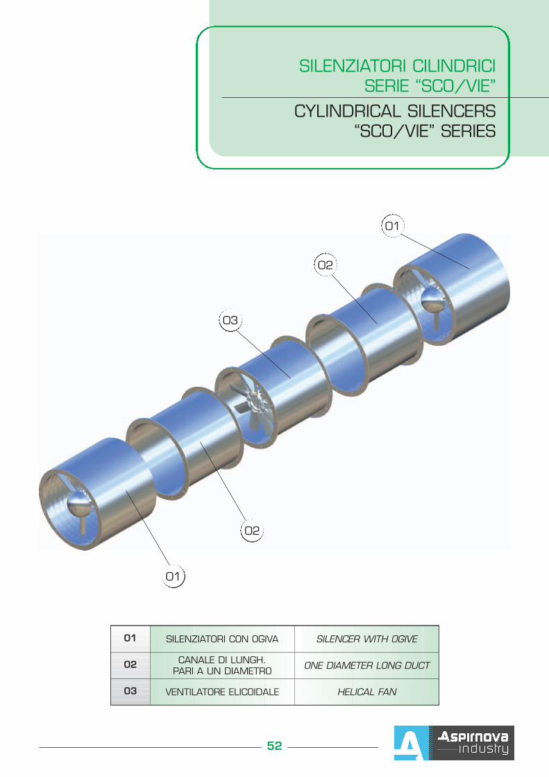
SILENZIATORI CILINDRICISERIE “SCO/VIE”
CYLINDRICAL SILENCERS“SCO/VIE” SERIES
01 SILENZIATORI CON OGIVA SILENCER WITH OGIVE
02 CANALE DI LUNGH. PARI A UN DIAMETRO ONE DIAMETER LONG DUCT
03 VENTILATORE ELICOIDALE HELICAL FAN
01
02
03
01
02
SILENZIATORI CILINDRICI SERIE SC/VIE - SCO/VIECYLINDRICAL SILENCERSSC/VIE - SCO/VIE SERIES
53
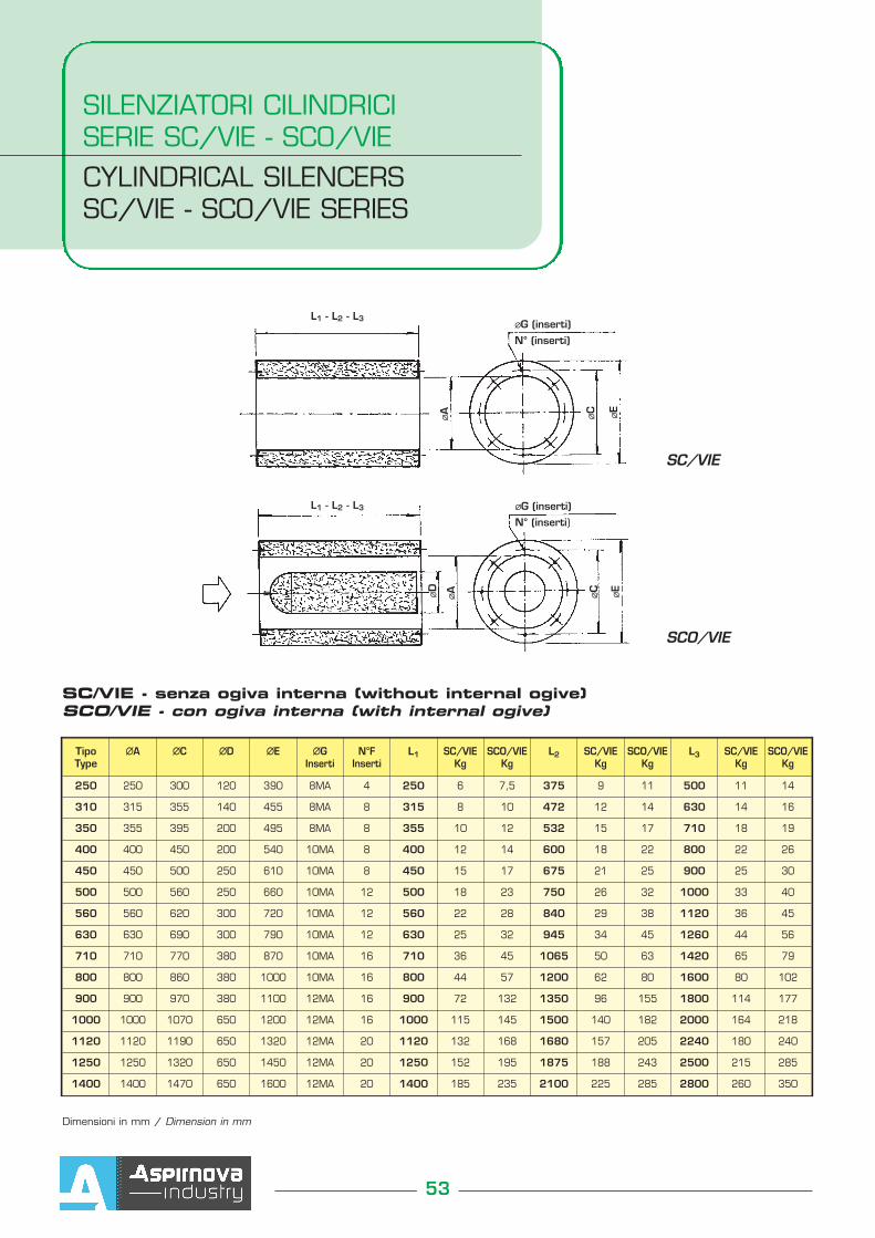
TipoType
∅∅A ∅∅C ∅∅D ∅∅E ∅∅GInserti
N°FInserti
L1 SC/VIEKg
SCO/VIEKg
L2 SC/VIEKg
SCO/VIEKg
L3 SC/VIEKg
SCO/VIEKg
250 250 300 120 390 8MA 4 250 6 7,5 375 9 11 500 11 14
310 315 355 140 455 8MA 8 315 8 10 472 12 14 630 14 16
350 355 395 200 495 8MA 8 355 10 12 532 15 17 710 18 19
400 400 450 200 540 10MA 8 400 12 14 600 18 22 800 22 26
450 450 500 250 610 10MA 8 450 15 17 675 21 25 900 25 30
500 500 560 250 660 10MA 12 500 18 23 750 26 32 1000 33 40
560 560 620 300 720 10MA 12 560 22 28 840 29 38 1120 36 45
630 630 690 300 790 10MA 12 630 25 32 945 34 45 1260 44 56
710 710 770 380 870 10MA 16 710 36 45 1065 50 63 1420 65 79
800 800 860 380 1000 10MA 16 800 44 57 1200 62 80 1600 80 102
900 900 970 380 1100 12MA 16 900 72 132 1350 96 155 1800 114 177
1000 1000 1070 650 1200 12MA 16 1000 115 145 1500 140 182 2000 164 218
1120 1120 1190 650 1320 12MA 20 1120 132 168 1680 157 205 2240 180 240
1250 1250 1320 650 1450 12MA 20 1250 152 195 1875 188 243 2500 215 285
1400 1400 1470 650 1600 12MA 20 1400 185 235 2100 225 285 2800 260 350
SC/VIE - senza ogiva interna (without internal ogive)SCO/VIE - con ogiva interna (with internal ogive)
Dimensioni in mm / Dimension in mm
L1 - L2 - L3
L1 - L2 - L3
∅∅G (inserti)
N° (inserti)
∅∅A
∅∅C
∅∅E
∅∅D
∅∅A
∅∅C
∅∅E
∅∅G (inserti)
N° (inserti)
SCO/VIE
SC/VIE
54
SILENZIATORI CILINDRICI SERIE SC/VIE - SCO/VIE
CYLINDRICAL SILENCERSSC/VIE - SCO/VIE SERIES
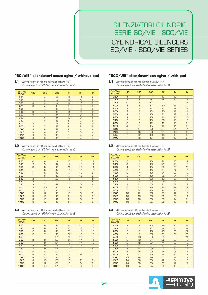
“SC/VIE” silenziatori senza ogiva / without pod
L1 Attenuazione in dB per banda di ottava (Hz)Octave spectrum (Hz) of noise attenuation in dB
L1 Attenuazione in dB per banda di ottava (Hz)Octave spectrum (Hz) of noise attenuation in dB
Tipo/TypeSC/VIE 125 250 500 1K 2K 4K
250 1 4 6 11 13 9310 1 3 8 14 9 8350 0 3 9 14 10 8400 0 4 10 13 8 8450 1 4 12 12 9 6500 0 4 13 11 9 6560 0 4 14 11 8 5630 1 5 14 10 9 5710 1 5 12 9 7 5800 3 7 9 8 6 5900 3 7 13 8 6 5
1000 3 8 12 8 4 41120 3 8 13 7 5 41250 3 9 13 7 4 41400 3 9 13 7 4 4
L3 Attenuazione in dB per banda di ottava (Hz)Octave spectrum (Hz) of noise attenuation in dB
L3 Attenuazione in dB per banda di ottava (Hz)Octave spectrum (Hz) of noise attenuation in dB
L2 Attenuazione in dB per banda di ottava (Hz)Octave spectrum (Hz) of noise attenuation in dB
L2 Attenuazione in dB per banda di ottava (Hz)Octave spectrum (Hz) of noise attenuation in dB
Tipo/TypeSC/VIE 125 250 500 1K 2K 4K
250 0 6 9 23 16 11310 2 5 12 19 13 11350 0 5 12 21 13 11400 1 5 14 19 12 10450 1 6 17 17 13 9500 1 6 18 17 12 9560 2 7 20 15 11 8630 2 7 20 14 12 8710 2 7 18 11 9 6800 5 10 13 12 9 7900 5 11 16 11 7 7
1000 5 12 17 10 6 61120 5 12 18 8 6 51250 6 12 17 8 5 51400 6 12 16 8 5 5
Tipo/TypeSC/VIE 125 250 500 1K 2K 4K
250 1 8 14 24 21 13310 6 6 16 26 17 13350 2 6 15 25 16 12400 2 7 18 24 15 12450 1 7 21 21 15 10500 2 8 23 21 14 11560 1 9 24 19 14 10630 2 9 25 17 14 10710 4 9 24 14 11 8800 6 13 22 14 10 9900 6 14 23 13 9 7
1000 6 16 23 12 7 71120 6 15 23 10 7 61250 8 17 22 10 6 61400 8 18 21 10 6 6
“SCO/VIE” silenziatori con ogiva / with pod
Tipo/TypeSCO/VIE 125 250 500 1K 2K 4K
250 1 4 7 13 20 14310 1 4 9 16 17 13350 0 4 11 22 21 15400 1 4 11 20 18 14450 1 6 14 21 19 13500 2 5 13 20 16 11560 1 6 15 21 17 11630 1 6 15 19 16 10710 2 7 15 20 18 12800 3 9 12 17 15 9900 4 8 15 16 11 8
1000 8 14 20 24 21 141120 6 13 20 21 14 81250 7 12 18 19 10 61400 7 12 17 18 10 6
Tipo/TypeSCO/VIE 125 250 500 1K 2K 4K
250 3 6 10 26 28 17310 4 5 13 23 26 18350 1 7 15 33 32 22400 2 6 15 31 27 19450 2 7 19 31 28 18500 3 7 19 29 24 14560 3 9 22 32 27 15630 2 9 22 29 23 14710 3 11 22 31 25 13800 6 13 18 26 22 12900 5 12 20 24 16 10
1000 10 22 30 37 29 161120 10 19 29 33 20 111250 10 18 26 29 14 91400 10 17 25 28 13 8
Tipo/TypeSCO/VIE 125 250 500 1K 2K 4K
250 1 9 15 29 26 21310 6 7 17 32 33 22350 2 8 19 40 39 27400 2 9 20 37 35 23450 3 10 23 39 36 21500 3 10 24 38 32 18560 2 12 27 41 35 18630 3 11 27 37 29 15710 5 14 29 41 32 18800 6 16 29 35 26 15900 7 17 30 34 20 12
1000 13 28 39 47 38 191120 14 26 36 42 24 131250 13 25 35 37 17 111400 13 24 34 36 16 10
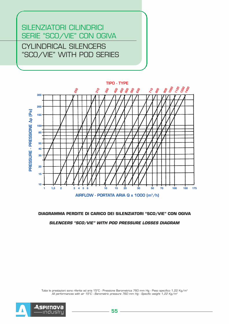
SILENZIATORI CILINDRICI SERIE “SCO/VIE” CON OGIVACYLINDRICAL SILENCERS“SCO/VIE” WITH POD SERIES
55
Tutte le prestazioni sono riferite ad aria 15°C - Pressione Barometrica 760 mm Hg - Peso specifico 1,22 Kg/m3
All performances with air 15°C - Barometric pressure 760 mm Hg - Specific weight 1,22 Kg/m3
DIAGRAMMA PERDITE DI CARICO DEI SILENZIATORI “SCO/VIE” CON OGIVA
SILENCERS “SCO/VIE” WITH POD PRESSURE LOSSES DIAGRAM
250
310
350
400
450
500
560
630
710
800
900
1000
1120
1250
1400
1 1,5 2 3 4 5 6 10 15 20 30 50 70 100 150 17510
300
200
150
100
80
50
40
30
20
15
TIPO - TYPE
AIRFLOW - PORTATA ARIA Q x 1000 (m3/h)
PR
ESSU
RE
- PR
ESSIO
NE
∆∆p
(Pa)