Embed Size (px)
Citation preview
Commission on Pile Research
Verification of geotechnical bearing
capacity of piles according to
Eurocode
Practical advice and recommendations
for project planning and control
Peter Alheid Gary Axelsson Bo Berggren Bo Berglars Ingemar Hermansson
Fredrik Sarvell
STOCKHOLM 2014
Report 106
PÅLKOMMISSIONEN
Commission on Pile Research Klara Norra Kyrkogata 31 Tel +46 (0)8-508 938 08 Fax +46 (0)8-508 938 01 Box 22307 104 22 STOCKHOLM
Report
Ordering Svensk Byggtjänst (Swedish Building Centre)www.byggtjanst.se 08-457 10 00
ISSN ISRN
0347-1047 IVA/PAL/R—14/106—SE
Print run 400 copies
Printing F4-Print AB, Stockholm, February 2014
Foreword
Following the introduction of Eurocode in Sweden, the design and verification of geotechnical bearing capacity has changed. This report provides an overview of methods for verifying the geotechnical bearing capacity of piles. The piles in question are driven precast concrete piles, driven steel piles, bored steel piles and piles fabricated in-situ with a cross-sectional dimension of less than 0.6 m.
As design, installation and verification are now to be performed in accordance with Eurocode, in February 2012 the Commission on Pile Research decided to develop an approach which was supported by Eurocode and previous regulations, with the aim of ensuring the correct quality for foundations with piles, avoiding misinterpretations of Eurocode and equating working methods and costs. The current report is the result of this work.
The parties who are most affected by piling in a foundation project are the client, the designer, the geotechnical engineer, the measurement technician and the contractor. The Commission on Pile Research believes for several reasons that these parties need a more clearly defined view of their responsibilities when it comes to the design and verification of the bearing capacity of piles.
With regard to financial planning and scheduling, it is important that everyone involved in a foundation project, from the ideas stage to project planning, development of tender documentation and final planning, installation and control, is aware of their part in the responsibility for achieving the intended project results, i.e.
• the client secures the financing for the project
• the planning engineer designs the construction and prepares the correct tender documentation
• the contractor carries out the foundation work in accordance with clear descriptions
• the geotechnical engineer performs appropriate tests
Eurocode specifies that the responsible geotechnical designer should participate in the design of geotechnical constructions. This is not always the case in practice. During the design of geotechnical constructions, the responsible geotechnical designer must take the following into account, among other things:
• geological and geotechnical conditions
• data from previous projects
• scope of laboratory and field investigations
• uncertainty in the calculation model
• type of fracture mechanism (brittle or tough)
The geotechnical bearing capacity of piles must be assessed or determined at various times, in various project planning stages, in technical descriptions, in the tender documentation and during the execution of the foundation work.
In the first phase of a construction project, the client decides to invest in the project. Cost limits and financing possibilities are established. Part of the project consists of ground and foundation work. The client must be aware that the geological conditions may entail special measures, which can be both expensive and time-consuming.
The next stage consists of the project planning, in which it may transpire that the foundation must be executed with piles. A preliminary piling plan is drawn up by the planning engineer in collaboration with the geotechnical engineer.
Verification of geotechnical bearing capacity of piles according to Eurocode
The piling plan includes the type and number of piles. Ideally, there should also be a description of how the bearing capacity of the piles will be verified and the scope of this verification.
The preliminary piling plan is one of the bases for the invitation to tender. A contractor is appointed, who generally engages a subcontractor to carry out the piling work. The subcontractor must accept the piling plan or, if not all the details have been specified, must, together with the responsible geotechnical designer, carry out his own design, which contains details of how the piling and the verification of bearing capacity are to be executed. The verification may include the performance of stress wave measurements in a test piling. The responsible geotechnical designer, together with the person performing the stress wave measurements, decides whether the piles meet the specified requirements for geotechnical bearing capacity. If conditions necessitate it, piles may be changed, installation procedures may be modified and additional controls may be necessary. It is therefore important, with regard to financial planning and scheduling, that everyone involved in the process, from the ideas stage to project planning, development of tender documentation and final planning, is aware of this and takes the appropriate responsibility.
Projects in which foundations are executed with piles come in different sizes, have different requirements in terms of durability and are carried out in different geological formations. For this reason, the scope of the verification of the geotechnical bearing capacity of the piles may also differ. The participants involved in the process may also have differing levels of knowledge of the significance of the various governing factors. It is essential to increase the knowledge of all participants, by means of information and training. The Swedish Geotechnical Society (SGF) plays a major role in this work; it has taken over responsibility for the documents and course plans that had been developed by IEG, the Commission for Implementing European Standards in Geotechnical Engineering.
This report has been prepared by a project group consisting of:
Bo Berggren Berggren Tech, group chair. Peter Alheid Hercules Grundläggning Gary Axelsson ELU Konsult Ingemar Hermansson Pålanalys i Göteborg Fredrik Sarvell Ruukki Sweden Bo Berglars Piling Development
The report has been reviewed by a reference group consisting of:
Gunnar Holmberg Skanska Sweden Per-Evert Bengtsson Swedish Geotechnical Institute Johan Lindgren Nilsson & Lindgren Markkonsult Kurt Palmqvist The Swedish Transport
Administration Karin Larsson Secretary to the Commission on Pile Research Lovisa Moritz The Swedish Transport Administration Hans Gullström Pålplintar
Stockholm, January 2014
Bo Berggren
Commission on Pile Research Report 106

Summary
This report gives rules and recommendations for the design and verification of the geotechnical bearing capacity of piles. The rules correspond to the requirements set out in Eurocode.
According to Boverket, the Swedish National Board of Housing, Building and Planning, the geotechnical bearing capacity of piles can be estimated and calculated using various methods. According to the rules set out by Trafikverket, the Swedish Transport Administration, which are linked to Eurocode, concrete piles for bridges can be driven to refusal in accordance with traditional measures in TK Geo (2011:46), Table 2.5-4, which is reproduced in the report in Table 5.1.
In Sweden, the dimensioning of the geotechnical bearing capacity of cohesion piles is most often performed using calculations in accordance with the Commission on Pile Research Report 100. Design values are established using IEG Report 8:2008, rev. 2, “Application document for EN 1997-1”, Chapter 7 Pile foundations, hereafter “TD Piles”.
The geotechnical bearing capacity of friction piles is usually designed according to Commission on Pile Research Report 103 ”Driven friction piles” with design values according to IEG report TD Piles.
The Commission on Pile Research report 97, “Steel core piles”, section 4.4, contains recommendations for calculating the geotechnical bearing capacity of both end-bearing and skin friction bearing steel core piles. Design values are established in accordance with IEG report TD Piles.
The Commission on Pile Research Report 102 deals with the geotechnical bearing capacities of injected piles.
The Commission on Pile Research Reports 100 and 103 contain sections on the calculation of geotechnical bearing capacity in tension piles. The Commission on Pile Research Report 97 “Steel core piles”, section 4.4.3, and TK Geo, section 2.5.1.3.1, including the Swedish Transport Administration's supplement, include the calculation of the geotechnical bearing capacity of skin friction steel core piles in tension.
Refusal simulations, WEAP and similar analyses are to be regarded as design by means of calculation and are used to develop refusal criteria and to estimate required hammer weights and drop heights for driving piles with larger dimensions and lengths than standard. This may apply, for example, to steel pipe piles with a diameter of 400 - 1000 mm. A WEAP analysis includes a number of assumptions concerning soil parameters, which is why dynamic testing should also be carried out in connection with the start of a project.
Test piling with stress wave measurements is often performed in Sweden continuously during the production phase. In consultation with the engineer responsible for the dynamic testing, the responsible geotechnical engineer decides during production on control with regard to any observed variations in the soil conditions. The division between production control and test piling is thus diffuse. The procedure is not always suitable, but test piling should be performed before production piling in order to be able to evaluate or determine the appropriate pile type, for example, with regard to pile-driving ability in soil with boulders, sloping rock and in thick hard till.
In large and complex piling works, it is recommended that test piling should be performed in good time before production, e.g. in order to develop well-substantiated tender documentation or to have time to order and produce piles of the correct type and dimensions.
Eurocode's execution instructions for piling work state that load tests must be performed in accordance with EN 1997-1 and ISO 22477-1 / -2 (currently only available as a draft). According to TRVFS (regulations by the Swedish Transport Administration) 2011:12 and BFS (regulations by the Swedish National Board of Housing, Building and Planning) 2013:10 EKS 9 section 7.5.3(1) in EN 1997-1, dynamic load tests must be calibrated with static load tests for piles of the same type, similar length and cross-section and similar soil conditions.
Verification of geotechnical bearing capacity of piles according to Eurocode

The Piling Foundations Handbook describes various methods for performing a static load test and evaluating fracture load using the creep method and in accordance with Commission on Pile Research Report 59. Dynamic load tests may be considered to be sufficiently reliable and correlated with static load tests for the following pile types and conditions:
• Driven steel and concrete piles (precast), which are mainly end-bearing on rock or non-cohesive soil (hard till).
• Precast skin friction bearing piles together with CAPWAP analyses.
• Steel core piles and bored steel pipe piles, end-bearing on rock or hard till.
• Skin friction steel core piles concreted into rock together with assessment of impact force at the top level of the concrete via the wave-up method.
The bearing capacity of end-bearing piles is calculated with the CASE method. A CAPWAP analysis should be performed for piles with a large skin friction resistance.
The bearing capacity can be estimated from stress wave measurements. According to both BFS and TRVFS, only 70 % of skin friction bearing capacity for compressive load may be used as tensile bearing capacity for piles in non-cohesive soils. A model factor of 1.3 should be used when the bearing capacity is evaluated with a CAPWAP analysis for skin friction piles where the end-bearing capacity is fully mobilised.
When designing by means of dynamic load testing, the design bearing capacity is based on mean or minimum values, determined by stress wave measurements in accordance with section 7.6 of this report. Design values for bearing capacity, determined via static load tests, are calculated in a similar way to dynamic load testing in accordance with section 7.6.2. Load tests, design values and choice of the number of representative piles should always be evaluated by qualified geotechnical personnel.
Effects of actions on piles should be calculated both for the limit state STR (structural design) and GEO (geotechnical design). Pile design according to Eurocode should be performed in accordance with design approach 3 (DA3) for STR and design approach 2 (DA2) for GEO.
When calculating negative skin friction for piles in clay, it is recommended that a corrected value with
respect to the liquid limit should be used for the undrained shear strength cu. For piles in non-cohesive
soils and over-consolidated clay soils under drained conditions, it may be assumed that the negative
skin friction resistance per unit of area is a function of the effective overburden pressure.
According to Eurocode, there are three limit levels of bearing capacity depending on the type of design and the scope of the verification. Tables 8.1 - 8.4 in the report show the recommended minimum quantities of measurements for each level for concrete piles and steel piles. In accordance with Chapter 9, larger quantities of measurements are required for larger load utilisation or when necessitated by piling conditions. The final quantity of measurements is decided after test piling, during production control or based on observations during piling. Tables 8.1 - 8.4 can be used during project planning or as a control level during procurement procedures for piling work, together with an accepted test quantity.
When designing via testing, the appropriate number of piles to be tested is strongly dependent on the geological conditions in the area. As a basis for the design values, stress wave measurements should be performed for at least four piles in accordance with TRVFS and BFS. The number of piles to be included in the determination of design values should constitute a representative basis with respect to the installation method, pile function and soil conditions at the site in question. Given that the soil properties may vary greatly, it is recommended that the distance between piles within a control area should not be too great. In the report it is suggested that the control area should not exceed 25×25 m2.
Commission on Pile Research Report 106
In TRVFS and BFS, the term “uniform geotechnical conditions” is used. Uniform conditions mean that there should be only minor variation with respect to
• Geological conditions
• Geotechnical properties
• Ground surface elevation
• Thickness of soil layers
• Rock surface elevation in the event of piles being founded on rock or close to rock
• Pile cap elevations
• Pile lengths and cross-sectional area
Eurocode states that production control of bearing capacity should be performed if observations during installation indicate large deviations from expected behaviour with respect to the geotechnical conditions or from earlier experience on site. Production control with determination of bearing capacity is generally performed by means of dynamic load tests or static tensile load tests. In small piling works with relatively few piles, a larger quantity of piles should be tested than that suggested in Table 9.1. Besides dynamic load testing, there are several methods that can be used for production control. The report gives suggestions for situations in which production control with load testing is recommended.
In many situations, load testing can be supplemented by other methods of production control. Examples of such methods include the counting of blows, recording of the number of blows per 0.2 m lowering of the pile and continuous registration of the hammer’s impact speed (driving energy).
Verification of geotechnical bearing capacity of piles according to Eurocode
Abstract
This report gives recommendations according to Eurocode on design and verification of geotechnical bearing capacity of piles.
According to Boverket, the Swedish National Board of Housing, Building and Planning, geotechnical bearing capacity can be estimated and calculated in different ways. According to Trafikverket, the Swedish Transport Administration, precast concrete piles can be driven to refusal following old- established measures in ”TK Geo, 2011:46”, see Table 5.1. in the report. TK Geo is linked to Eurocode.
In Sweden the Swedish Pile Commission has published reports where recommendations are given on designing the geotechnical bearing capacity, e.g.:
• Design of the geotechnical bearing capacity of cohesion bearing piles is commonly made using Report 100. Design values are established using IEG Report 8:2008 rev 2 ”Tillämpningsdokument för EN 1997-1”, hereafter ”TD Piles”.
• The geotechnical bearing capacity of friction bearing piles is usually designed according to Report 103 ”Driven friction piles” with design values according to TD Piles.
• In Report 97 ”Stålkärnepålar” recommendations are given to calculate the geotechnical bearing capacity of both point bearing and skin friction bearing steel core piles. Design values according to TD Piles.
• In Report 102 geotechnical bearing capacities of injected piles are found.
• Reports 100 and 103 give recommendations on calculation of geotechnical bearing capacity in tension piles. Report 97 and TK Geo give recommendations on calculation of geotechnical bearing capacity of skin friction steel core piles in tension.
WEAP and similar analyses are to be regarded as design via calculation and are used to estimate driving criteria including drop height for large diameter piles, develop refusal criteria and to estimate required drop height for driving piles with large dimensions and lengths, e.g. steel tube piles with diameters between 400 and 1000 mm.
Test piling with stress wave measurements is often performed in Sweden continuously during the production phase. The responsible geotechnical engineer and the engineer responsible for the dynamic testing decide during production on control regarding observed variations in the soil conditions. The division between production control and test piling is thereby diffuse. The procedure is not always suitable especially in soil with boulders or in thick hard till or where sloping rock surface can be found.
In large and complex piling works test piling should be performed in good time before production, e.g. to established high quality specifications and to order or produce piles of right type and dimensions.
Eurocode demands load testing according to EN 1997-1 and ISO 22477-1 and -2. According to BFS, regulations by the Swedish National Board of Housing, Building and Planning, and TRVFS, regulations by the Swedish Transport Administration, dynamic load tests shall be calibrated with static load tests for piles of the same type, similar length and dimension and similar soil conditions. In Sweden dynamic load tests are considered to be calibrated with static load tests for the following pile types and conditions:
• Driven steel and precast concrete piles mainly point bearing on rock or hard till.
• Precast concrete skin friction concrete bearing piles together with CAPWAP analyses.
Commission on Pile Research Report 106

Verification of geotechnical bearing capacity of piles according to Eurocode
• Steel core piles and drilled steel pipe piles, point bearing on rock and hard till.
• Skin friction steel core piles concreted into rock together with calculated dynamic force at the top level of the concrete via the wave-up method.
The bearing capacity of point bearing piles is calculated with the CASE method while the CAPWAP method is used for piles with a large portion of skin friction resistance.
The bearing capacity of tensile piles can be estimated from stress wave measurements. According to TRVFS and BFS only 70 % of skin friction bearing capacity is allowed as tensile bearing capacity of piles in non-cohesive soils. A model factor of 1.3 shall be used when the bearing capacity is evaluated with a CAPWAP analysis for skin friction piles where the point bearing capacity is fully mobilised.
When designing via dynamic load testing the design bearing capacity is based on mean values or min value of stress wave measurements. Design via static load tests is made similarly. Load tests and design and choice of representative piles shall always be evaluated by qualified geotechnical personnel.
Load effect on piles shall be calculated both in limit state STR (structural design) and GEO (geotechnical design). Pile design according to Eurocode shall be made according to design approach DA3 in STR and design approach DA2 in GEO.
When calculating negative skin friction for piles in cohesive soils the report recommends a corrected value of undrained shear strength cu with respect to liquid limit. For piles in non-cohesive soils and over-consolidated cohesive soils in drained conditions the negative skin friction resistance should be calculated as a function of the effective overburden pressure.
According to Eurocode there are three levels of bearing capacity depending on the type of design and the quantity of the verification. In Tables 8.1 - 8.4 in the report minimum quantities of measurements are recommended in each class for precast concrete piles and steel piles. Larger quantity is required for larger load utilisation and when piling conditions so demands. The final quantity of measurements is decided after test piling, during production control or based on observations during piling. Tables 8.1 - 8.4 can be used in preliminary design, as regulation level at procurement together with an accepted test quantity.
When designing via testing the number of piles to be tested is strongly dependent on the geo conditions. As a basis stress wave measurement shall be performed for at least four piles according to TRVFS and BFS. The number of piles shall be representative with respect to installation method, pile function and soil conditions. In the report it is recommended that the control area does not exceed 25×25 m2 but when soil conditions and properties may have a large variation it is recommended to choose a small distance between test piles in a control object area.
In TRVFS and BFS the concept of ”uniform geotechnical conditions” is utilised, meaning that the variation shall be small with respect to
• Geological conditions
• Geotechnical properties
• Ground surface elevation
• Thickness of soil layers
• Rock surface elevation when piles are founded on rock or close to rock
• Pile cap elevations
• Pile lengths and dimensions
Eurocode states that production control of bearing capacity shall be made when observations during installation implies large deviation from expected behaviour with respect to geotechnical conditions or from earlier experience at site.
Production control through determination of bearing capacity is commonly made with dynamic load tests or with static tensile load tests. In small piling works with relatively few piles a larger quantity of piles than in Table 9.1 should be tested. Besides dynamic load testing there are several methods that can be used in production control to get a better view of the piling results. In the report suggestions are given for situations where load tests are recommended.
Commission on Pile Research Report 106
Table of Contents
FOREWORD ...................................................................................................................................................... 3
SUMMARY ....................................................................................................................................................... 5
ABSTRACT ........................................................................................................................................................ 8
TABLE OF CONTENTS ........................................................................................................................................ 9
1 INTRODUCTION ..................................................................................................................................... 13
1.1 BACKGROUND AND PURPOSE ............................................................................................................... 13
1.2 DELIMITATIONS .................................................................................................................................. 13
1.3 PRECONDITIONS ................................................................................................................................. 13
1.4 CONTENT OF THE REPORT .................................................................................................................... 14
2 HISTORICAL BACKGROUND ................................................................................................................... 18
2.1 GENERAL ........................................................................................................................................... 18
2.2 DRIVING TO REFUSAL IN ACCORDANCE WITH STRESS WAVE THEORY .......................................................... 19
2.2.1 SBN 1975:8 ................................................................................................................................. 19 2.2.2 Commission on Pile Research, Application instructions for driving concrete piles to refusal (1982) 19 2.2.3 Commission on Pile Research report 92 ....................................................................................... 20 2.2.4 BRO 94 ....................................................................................................................................... 20 2.2.5 Commission on Pile Research report 94 ....................................................................................... 21 2.2.6 Commission on Pile Research report 98 ....................................................................................... 21
3 GOVERNING DOCUMENTS ...................................................................................................................... 24
3.1 GENERAL ........................................................................................................................................... 24
3.1.1 Applicable standards ................................................................................................................. 24 3.1.2 National adaptations of standards ............................................................................................ 24 3.1.3 Execution standards ................................................................................................................... 24 3.1.4 Requirements and technical descriptions .................................................................................... 25 3.1.5 Other documents dealing with the geotechnical design of piles ................................................... 25
4 ACTION EFFECTS ..................................................................................................................................... 26
4.1 GENERAL ........................................................................................................................................... 26
4.2 ACTION EFFECT ON PILES FOR STR INCLUDING NEGATIVE SKIN FRICTION .................................................. 26
4.3 ACTION EFFECT ON PILES FOR GEO INCLUDING NEGATIVE SKIN FRICTION ................................................. 28
4.4 DESIGN VALUES FOR LOADS ................................................................................................................. 28
4.5 CALCULATION MODELS FOR NEGATIVE SKIN FRICTION ............................................................................. 29
5 TRADITIONAL MEASURES ....................................................................................................................... 31
5.1 DRIVING CONCRETE PILES TO REFUSAL ACCORDING TO TK GEO (2011:46) ............................................... 31
5.2 DRIVING CONCRETE PILES TO REFUSAL ACCORDING TO COMMISSION ON PILE RESEARCH REPORT 94 ........... 31
5.3 DRIVING STEEL PILES TO REFUSAL .......................................................................................................... 32
6 DESIGN BY CALCULATION ....................................................................................................................... 36
6.1 GENERAL ........................................................................................................................................... 36
6.2 COHESION PILES ................................................................................................................................. 36
6.3 FRICTION PILES ................................................................................................................................... 37
6.4 STEEL CORE PILES ................................................................................................................................ 37
6.5 INJECTED PILES ................................................................................................................................... 38
6.6 PILES UNDER TENSION ......................................................................................................................... 38
Verification of geotechnical bearing capacity of piles according to Eurocode
6.7 DRIVING SIMULATION ......................................................................................................................... 39
7 DESIGN BY CALCULATION ....................................................................................................................... 40
7.1 GENERAL.......................................................................................................................................................... 40
7.2 TEST PILING, EXECUTION and QUANTITY................................................................................................. 41 7.3 EVALUATION OF BEARING CAPACITY WITH STATIC LOAD TESTING .................................................................... 42 7.4 EVALUATION OF BEARING CAPACITY WITH DYNAMIC LOAD TESTING ................................................................ 42
7.5 EVALUATION OF BEARING CAPACITY FOR TENSILE LOAD ........................................................................... 43
7.6 DESIGN BY TESTING ............................................................................................................................. 43
7.6.1 Dynamic load testing .................................................................................................................. 43 7.6.2 Static load testing ....................................................................................................................... 46
8 PRELIMINARY ASSESSMENT OF BEARING CAPACITY ............................................................................... 47
8.1 TOE RESISTANCE IN ROCK AND HARD TILL ............................................................................................... 47
8.2 BEARING CAPACITY THAT CAN BE DEMONSTRATED BY STRESS WAVE MEASUREMENT .................................. 48
8.3 EMPIRICAL VALUES FROM STRESS WAVE MEASUREMENTS, K1 .......................................................................... 51 8.4 STRESS MONITORING, K2 ................................................................................................................................. 52 8.5 EFFECT OF PILE LENGTH AND HAMMER WEIGHT .............................................................................................. 52
9 PRODUCTION CONTROL WITH DETERMINATION OF BEARING CAPACITY .................................................... 54
9.1 GENERAL.......................................................................................................................................................... 54
9.2 SUGGESTIONS FOR PRODUCTION CONTROL ............................................................................................ 54
9.3 COMPLEMENTARY CONTROL METHODS ................................................................................................. 56
10 GUIDELINES FOR THE PERFORMANCE OF TESTING ............................................................................ 57
10.1 PREPARATORY WORK ....................................................................................................................................... 57 10.2 TEST PILING ...................................................................................................................................................... 58
10.3 RE-DRIVING ........................................................................................................................................ 58 10.4 EVALUATION OF BEARING CAPACITY .................................................................................................................. 58
10.5EVALUATION OF REFUSAL CRITERIA/DRIVING DEPTH ................................................................................. 59
10.6 PRODUCTION CONTROL of PILES ............................................................................................................ 59 10.7 EVALUATION OF PRODUCTION CONTROL .......................................................................................................... 60 10.8 INTEGRITY CONTROL ......................................................................................................................................... 60 10.9 TEST PILING WITH STATIC LOAD TESTING ........................................................................................................... 60
11 GUIDELINES FOR THE REPORTING OF TESTING ........................................................................................ 62
11.1 TEST PILING WITH STRESS WAVE MEASUREMENT .............................................................................................. 62
11.2 PRODUCTION CONTROL ........................................................................................................................ 62
11.3 INTEGRITY CONTROL ............................................................................................................................ 63 11.4 TEST PILING WITH STATIC LOAD TESTING ........................................................................................................... 63
12 REFERENCES ............................................................................................................................................ 64
A CALCULATION EXAMPLE ......................................................................................................................... 65
A.1 DRIVEN END-BEARING STEEL PIPE PILES IN ROCK ....................................................................................... 65
A. A.2 DRIVEN END-BEARING CONCRETE PILES IN HARD TILL .......................................................................... 67
B COMPARISON BETWEEN NEW AND OLD REGULATIONS FOR STRESS WAVE MEASUREMENT ................. 69
B. 1 SS-EN 1997 + NATIONAL ANNEXES ............................................................................................................. 69
B.2 BRO 2004 VS TRVFS 2011:12 ............................................................................................................ 70
B.3 BRO 2004 VS TRVFS 2011:12 WITH RIGID FOUNDATIONS ............................................................................ 72
B.4 COMMISSION ON PILE RESEARCH REPORT 98 COMPARED to BFS 2013:10 ................................................ 73
B.5 THE PILING FOUNDATIONS HANDBOOK COMPARED to BFS 2013:10 ........................................................ 74
B.6 BFS 2013:10 COMPARED TO TRVFS 2011:12 WITH RIGID FOUNDATIONS ..................................................... 75
Commission on Pile Research Report 106
1 Introduction
1.1 Background and purpose
With the introduction of Eurocode in Sweden, the procedure for the verification of geotechnical bearing capacity has changed. Firstly, this relates to which safety factors should be applied to measured stress wave values, both mean and minimum values, which is in part connected with the fact that safety has been moved from the bearing capacity side to the action effect side; secondly, it relates to how Eurocode deals with testing and production control. Furthermore, the regulatory authorities, the Swedish National Board of Housing, Building and Planning and the Swedish Transport Administration, have made various assessments with regard to certain partial coefficients. Given that these are new regulations, different interpretations have also emerged of certain parts of them, which is entirely understandable, but perhaps not desirable. The information in the Eurocodes is also spread over several documents, which in some cases has made it less comprehensible. For these reasons and in response to calls from the industry, the Commission on Pile Research has decided to issue consolidated recommendations in order to give the industry a common working platform, with standardised rules, and in this way to equate working methods and costs.
1.2 Delimitations
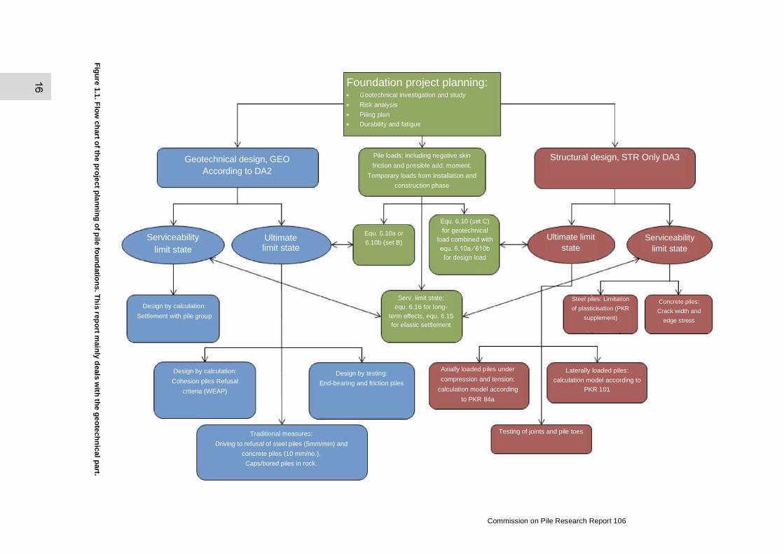
In order to clarify the scope and delimitation of this report, Figure 1.1 shows a flow chart of pile project planning, in which the parts dealt with in this Report are marked in blue, i.e. the verification of geotechnical bearing capacity. To some extent, other parts are also affected, especially the effects of actions on piles (the green parts). The parts marked in red concern the verification of structural (design) bearing capacity, previously often referred to as load capacity, capacity against buckling etc.
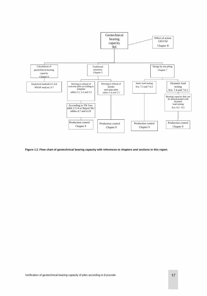
Figure 1.2 shows another flow chart, which partly overlaps with the first, concerning geotechnical bearing capacity, with references to chapters and instructions in this report.
1.3 Preconditions
The content of this report can, of course, be read with interest by all parties involved in the foundation process.
SS-EN 1997-1 is intended for clients, designers, contractors and public authorities, and provides guidance for the geotechnical design of buildings and facilities; it is intended to be applied in conjunction with EN 1990 - 1999.
Section 1.3 of SS-EN 1997-1 specifies the conditions on which the standard is based:
• Information required for the design must be collected, registered and interpreted by suitably qualified personnel.
• The construction must be dimensioned by suitably qualified and experienced personnel.
• There must be appropriate collaboration between all the personnel who work with data collection, design and construction.
• Adequate supervision and quality control must be implemented and performed on construction sites.
Verification of geotechnical bearing capacity of piles according to Eurocode
• The work must be executed in accordance with relevant standards and specifications by personnel with sufficient competence and experience.
• Construction materials and products must be used in accordance with the specifications set out in the standard (SS-EN 1997-1) or in relevant material or product specifications.
• The construction must be used for the purpose stated in the design.
It is furthermore specified that these conditions must be observed by both the designer and the customer. This, of course, represents no difference to how work was conducted previously.
Please note therefore that the person who chooses a pile for a specified action effect (structural/design bearing capacity) or who chooses the method for verifying this action effect (geotechnical bearing capacity) should be regarded as the responsible geotechnical designer and must therefore also be suitably qualified and experienced for the task in hand. This designer is also responsible for checking that the preconditions underlying the design are also met, such as straightness, length, surrounding piles etc. In addition, he/she is also responsible for the piling’s environmental impact, stability, bearing capacity for the machinery that is required to perform the work etc. This responsibility may also include preparing and following up a control plan/control programme.
In order to be approved, the construction product (the pile) must also have assessed properties. This term should replace the terms “type-approved” or “manufacturing-controlled” materials and products. In accordance with BFS 2013:10, EKS9, section 4, construction products with assessed properties are defined as products that have been manufactured for permanent inclusion in construction works. In the same section, points a) to d) specify which products are considered to have assessed properties;
a) Products with a CE marking. Concrete piles with associated fittings are manufactured in accordance with SS-EN 12794. Since SS-EN 12794 is a harmonised standard, with effect from 1 July 2013 it is a requirement that concrete piles must have a CE marking.
b) Products that have been type-approved and/or production-controlled in accordance with the provisions of Chapter 8, Sections 22-23 of the Swedish Planning and Building Act (2010:900). Steel piles are not covered by any harmonised standard, which means that for the time being they can be type-approved. It is, however, possible to voluntarily CE-mark steel piles and to declare the product’s properties in accordance with an ETA (European Technical Approval).
c) Products that have been certified by a certification body accredited for the task and product in question in accordance with Regulation (EC) No 765/2008 of 9 July 2008 setting out the requirements for accreditation and market surveillance relating to the marketing of products and repealing Regulation (EEC) No 339/93.
d) Products that have been manufactured in a factory in which the manufacture and production control and the results thereof for the construction product are continuously monitored, assessed and approved by a certification body accredited for the task and product in question in accordance with Regulation (EC) No 765/2008.
In order for the construction product to be deemed to have assessed properties, when alternatives c) and d) are applied the verification must be of such a scope and quality to ensure that the stated material and product properties correspond to the actual properties. The verification must at the minimum correspond to what has been decided for the CE marking of similar products.
Finally, the pile must be installed in accordance with the relevant normative execution standards. These are specified in section 3.1.3 and apply to bored piles, micropiles and displacement piles.
1.4 Content of the report
This report can be read in its entirety or in the applicable parts.
Chapter 2 gives a brief history of the verification of the geotechnical bearing capacity of piles in Sweden.
Chapter 3 presents the documents that govern the design of geotechnical bearing capacity.
Commission on Pile Research Report 106
Chapter 4 contains a review of which action effects on piles must be verified by the geotechnical bearing capacity. In accordance with SS-EN 1997-1, action effects on piles must be calculated both for the limit state STR (marked in red) and GEO (marked in blue), see Figure 1.1. Since the pile’s structural bearing capacity is designed using design method 3 (DA3) for STR and the pile’s geotechnical bearing capacity is verified using design method 2 (DA2) for GEO, the action effects are also calculated differently. The chapter on Action effects also describes a recommended procedure for calculating design action effects in the event of negative skin friction. IEG report 8:2008, rev 2, Application document for EN 1997-1, Chapter 7 Pile foundations (TD Piles) gives examples of how the safety class can be selected for piles in STR and in GEO. It is therefore not uncommon that the load to be verified (e.g. using stress wave measurement) is not the same as the load to be verified by calculation of the pile element’s structural bearing capacity with respect to flexural buckling.
Chapters 5, 6 and 7 describe various methods for verifying geotechnical bearing capacity, with traditional measures, by calculation and by testing/test piling. Please note that Eurocode makes a clear distinction between testing/test piling sampling and production control, which in Sweden have increasingly tended to become merged in recent years.
Chapter 8 presents methods for the preliminary assessment of the geotechnical bearing capacity that can be achieved for a pile.
Chapter 9 defines various types of production control, predominantly control by means of load testing, but also alternatives that are recommended for various types of projects.
Chapters 10 and 11 contain recommended guidelines for performing and reporting dynamic load testing and production control.
Appendix A presents two calculation examples for a typical driven slender steel pile and a driven concrete pile, while Appendix B shows a comparison between the old and new regulations for stress wave measurements.
Verification of geotechnical bearing capacity of piles according to Eurocode
Fig
ure
1.1
. Flo
w c
hart o
f the p
roje
ct p
lan
nin
g o
f pile
fou
nd
atio
ns
. Th
is re
po
rt main
ly d
eals
with
the g
eo
tech
nic
al p
art.
Serv. limit state:
equ. 6.16 for long-
term effects, equ. 6.15
for elastic settlement
Equ. 6.10 (set C)
for geotechnical
load combined with
equ. 6.10a ∕ 610b
for design load
Equ. 6.10a or
6.10b (set B) Ultimate limit state
Geotechnical design, GEO
According to DA2
Serviceability
limit state
Pile loads: including negative skin
friction and possible add. moment.
Temporary loads from installation and
construction phase
Foundation project planning: • Geotechnical investigation and study
• Risk analysis
• Piling plan
• Durability and fatigue
Structural design, STR Only DA3
Ultimate limit
state
Serviceability
limit state
Steel piles: Limitation
of plasticisation (PKR
supplement)
Concrete piles:
Crack width and
edge stress
Axially loaded piles under
compression and tension:
calculation model according
to PKR 84a
Testing of joints and pile toes
Laterally loaded piles:
calculation model according to
PKR 101
Design by testing:
End-bearing and friction piles
Design by calculation:
Cohesion piles Refusal
criteria (WEAP)
Traditional measures:
Driving to refusal of steel piles (5mm/min) and
concrete piles (10 mm/no.).
Caps/bored piles in rock.
Design by calculation:
Settlement with pile group
Commission on Pile Research Report 106
Driving to refusal of
slender
steel pipe piles
tables 5.4 and 5.5
Traditional
measures
Chapter 5
Driving to refusal of concrete piles according to
template
tables 5.1, 5.2 and 5.3
According to TK Geo table 2.5-4 or Report 94,
tables 4.7 and 4.10
Production control
Chapter 9 Production control
Chapter 9
Production control
Chapter 9
Production control
Chapter 9
Bearing capacity that can be demonstrated with
dynamic load testing
Scn. 8.2 - 8.5
Dynamic load
testing
Scn. 7.4 and 7.6.1
Static load testing
Scn. 7.3 and 7.6.2
Design by test piling
Chapter 7
Effect of action
GEO Ed
Chapter 4
Geotechnical
bearing
capacity
Rd
Calculations of
geotechnical bearing
capacity
Chapter 6
Analytical methods 6.1-6.6
WEAP analysis, 6.7
Figure 1.2. Flow chart of geotechnical bearing capacity with references to chapters and sections in this report.
Verification of geotechnical bearing capacity of piles according to Eurocode

2 Historical background
2.1 General
Regulations for driving to refusal and stress wave measurements of piles for the verification of their geotechnical bearing capacity have a long tradition in Sweden. One of the first projects in which stress wave measurement was documented was during the rebuilding of the Stockholm Telephone Exchange in the 1940s, when stress wave measurements were performed on steel piles. The measurements were carried out by mounting a special measuring pad on top of several steel piles, in which the upper and lower parts were separated by a number of blackened steel balls. The piles were then driven with different drop heights, after which the measuring pad was unscrewed and the blackened impression caused by these balls on the top and bottom of the pad was measured. With the help of calculation formulas based on Hertzian contact stress, the approximate impact force on the pile could be calculated.
Another very early stress wave measurement, which was commissioned by the Royal Swedish Academy of Engineering Sciences’ Pile Committee, subsequently the Commission on Pile Research, was the driving and load testing of long concrete piles for the foundations of a bridge in Gubbero, Gothenburg. In piles of 60-70 m in length, wire strain gauges were mounted on reinforcing bars at various levels. Measurement signals were conducted to the top of the piles by means of embedded cables. The measurements were generally carried out at a level of approximately 2-3 m and 20-25 m up from the pile toe. The piling was evaluated with driving to refusal formulas, stress wave measurements and static load testing. The testing is documented in Report 99 (1964) from the Swedish Council for Building Research.
In the mid-1970s, stress wave measurements were increasingly introduced as an aid in determining the geotechnical bearing capacity of piles. Previously, stress wave measurements had been used primarily for the purposes of research in various projects. The CASE method began to be used more widely in the field as measuring sensors and computer systems were becoming more suitable for on-site usage.
The term “Type approval” has had a somewhat varied meaning over the years. In the early 1990s type approval for various types of piles covered the whole piling system, i.e. fabrication, transportation, installation, design with regard to load capacity in the ultimate and serviceability limit states and verification of the geotechnical bearing capacity. Type approval included system descriptions, project planning instructions and extensive testing.
Some manufacturers also developed their own system for developing safety factors for dynamic shockwave measurements, based on the beta method, which took account of the variation in the results and the quantity of piles tested. This is the reason for the mentions of “Type-approved pile systems” on construction drawings which can still be seen today.
Around a decade later, the rules for type approvals were changed, so that the only thing that could be type-approved was the manufactured product/pile itself; since that time there have been no type-approved pile systems, only pile elements.
In the case of concrete piles, the old standard SS811103, which included SP1-3, was withdrawn in September 2005 and replaced by SS-EN 12794, which constitutes a framework for precast concrete piles. The design of concrete piles is now much freer, and the piles can be optimised for their application in a completely different way. As a small clarification for concrete piles, it should be mentioned that since SP1, SP2 and SP3 piles do not in any way essentially contravene SS-EN 12794, piles with these designations are still manufactured. As the designations are well known and the pile configuration itself (lateral dimensions, reinforcement content etc.) is already optimised for Swedish conditions, they continue in existence, even if unofficially.
Commission on Pile Research Report 106
SS-EN 12794 is a harmonised standard (hEN), which means that concrete piles must now have a CE marking in order to be used as a construction product. Since there is a harmonised standard for the manufacture of concrete piles, concrete piles can no longer be type-approved. There is no hEN standard for steel pipe piles, which is why these piles can instead be CE marked in accordance with an ETA (European Technical Approval). Type approvals for steel pipe piles can still be issued until such time as a hEN standard has been ratified.
2.2 Driving to refusal in accordance with stress wave theory
2.2.1 SBN 1975:8
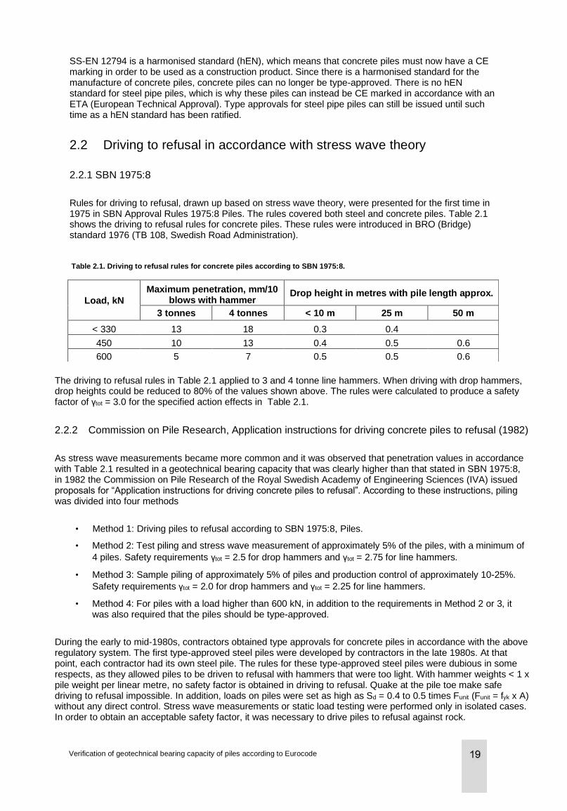
Rules for driving to refusal, drawn up based on stress wave theory, were presented for the first time in 1975 in SBN Approval Rules 1975:8 Piles. The rules covered both steel and concrete piles. Table 2.1 shows the driving to refusal rules for concrete piles. These rules were introduced in BRO (Bridge) standard 1976 (TB 108, Swedish Road Administration).
Table 2.1. Driving to refusal rules for concrete piles according to SBN 1975:8.
Load, kN
Maximum penetration, mm/10 blows with hammer
Drop height in metres with pile length approx.
3 tonnes 4 tonnes < 10 m 25 m 50 m
< 330 13 18 0.3 0.4
450 10 13 0.4 0.5 0.6
600 5 7 0.5 0.5 0.6
The driving to refusal rules in Table 2.1 applied to 3 and 4 tonne line hammers. When driving with drop hammers, drop heights could be reduced to 80% of the values shown above. The rules were calculated to produce a safety factor of γtot = 3.0 for the specified action effects in Table 2.1.
2.2.2 Commission on Pile Research, Application instructions for driving concrete piles to refusal (1982)
As stress wave measurements became more common and it was observed that penetration values in accordance with Table 2.1 resulted in a geotechnical bearing capacity that was clearly higher than that stated in SBN 1975:8, in 1982 the Commission on Pile Research of the Royal Swedish Academy of Engineering Sciences (IVA) issued proposals for “Application instructions for driving concrete piles to refusal”. According to these instructions, piling was divided into four methods
• Method 1: Driving piles to refusal according to SBN 1975:8, Piles.
• Method 2: Test piling and stress wave measurement of approximately 5% of the piles, with a minimum of
4 piles. Safety requirements γtot = 2.5 for drop hammers and γtot = 2.75 for line hammers.
• Method 3: Sample piling of approximately 5% of piles and production control of approximately 10-25%.
Safety requirements γtot = 2.0 for drop hammers and γtot = 2.25 for line hammers.
• Method 4: For piles with a load higher than 600 kN, in addition to the requirements in Method 2 or 3, it was also required that the piles should be type-approved.
During the early to mid-1980s, contractors obtained type approvals for concrete piles in accordance with the above regulatory system. The first type-approved steel piles were developed by contractors in the late 1980s. At that point, each contractor had its own steel pile. The rules for these type-approved steel piles were dubious in some respects, as they allowed piles to be driven to refusal with hammers that were too light. With hammer weights < 1 x pile weight per linear metre, no safety factor is obtained in driving to refusal. Quake at the pile toe make safe driving to refusal impossible. In addition, loads on piles were set as high as Sd = 0.4 to 0.5 times Funit (Funit = fyk x A) without any direct control. Stress wave measurements or static load testing were performed only in isolated cases. In order to obtain an acceptable safety factor, it was necessary to drive piles to refusal against rock.
Verification of geotechnical bearing capacity of piles according to Eurocode
The “System piles” piling system was described in Commission on Pile Research report 81 (1989). Requirements for hammer weights in relation to pile weight per linear metre were not introduced until 2000 in Commission on Pile Research report 98.
The first steel pile for which requirements were placed on stress wave controls for large loads was Gustavsberg’s G-pile, which was type-approved in 1991. In a similar fashion to concrete piles, the piling was divided into three piling methods:
• Method 1: Max load Sd = 0.28 × Funit, driving to refusal only
• Method 2: Max load Sd = 0.35 × Funit, stress wave control minimum 10%
• Method 3: Maxload Sd = 0,45 × Funit, stress wave control minimum 25 %
In the early 1980s, the simulation program WEAP was used to study the influence of various factors on the bearing capacity of piles as a function of penetration, Commission on Pile Research Report 68, Parameter study.
In the late 1980s and early 1990s, work began on computer calculations of driving to refusal. With the computer simulation of driving to refusal, it was possible to calculate the hammer weights, drop heights and penetrations required for driving piles to refusal with an acceptable geotechnical bearing capacity. Results from the computer calculations were compared with results from the stress wave measurements.
2.2.3 Commission on Pile Research report 92
Commission on Pile Research report 92 (1993) “Computer simulation of pile driving” describes how to work with computer calculations of pile driving and how to calculate driving to refusal rules for various piles and loads. With the computer simulation of pile driving, it is also possible to calculate the interplay of forces in the pile under tension and compression for various driving conditions. After this report, the computer calculation of driving to refusal came to be used in the subsequent work on rules for driving to refusal.
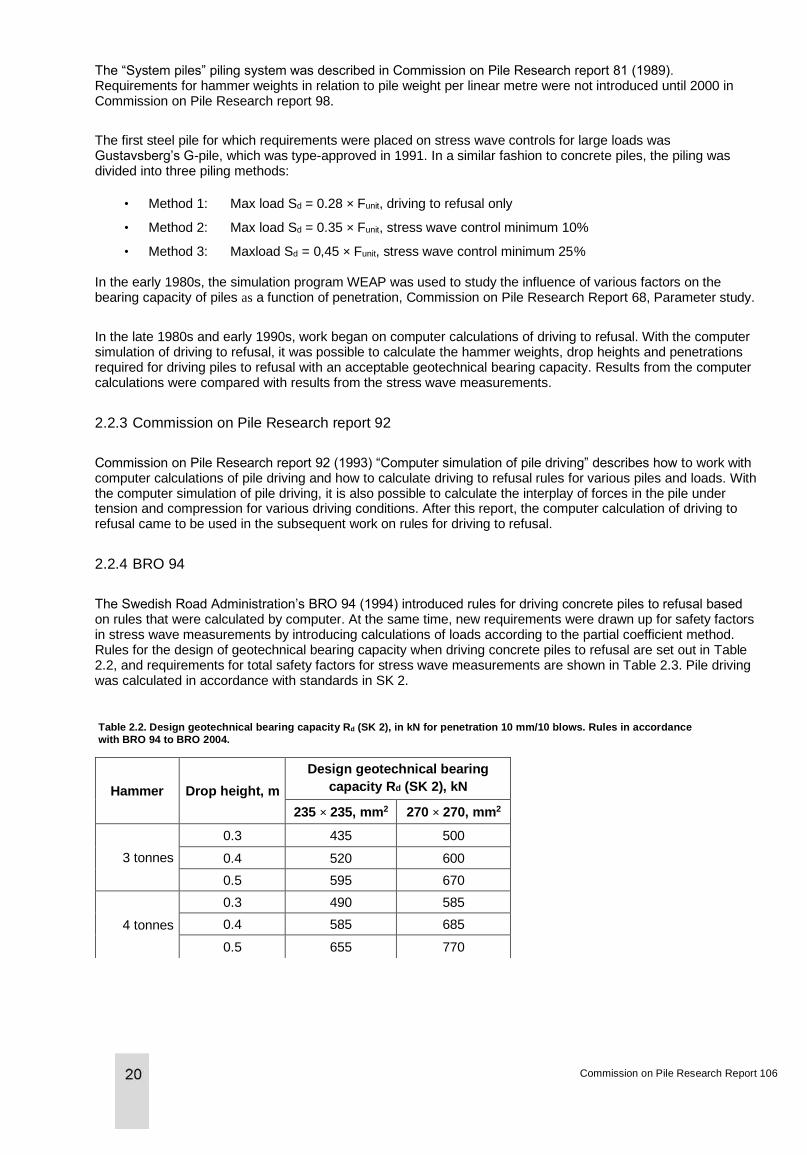
2.2.4 BRO 94
The Swedish Road Administration’s BRO 94 (1994) introduced rules for driving concrete piles to refusal based on rules that were calculated by computer. At the same time, new requirements were drawn up for safety factors in stress wave measurements by introducing calculations of loads according to the partial coefficient method. Rules for the design of geotechnical bearing capacity when driving concrete piles to refusal are set out in Table 2.2, and requirements for total safety factors for stress wave measurements are shown in Table 2.3. Pile driving was calculated in accordance with standards in SK 2.
Table 2.2. Design geotechnical bearing capacity Rd (SK 2), in kN for penetration 10 mm/10 blows. Rules in accordance
with BRO 94 to BRO 2004.
Hammer Drop height, m
Design geotechnical bearing
capacity Rd (SK 2), kN
235 × 235, mm2 270 × 270, mm2
3 tonnes
0.3 435 500
0.4 520 600
0.5 595 670
4 tonnes
0.3 490 585
0.4 585 685
0.5 655 770
Commission on Pile Research Report 106
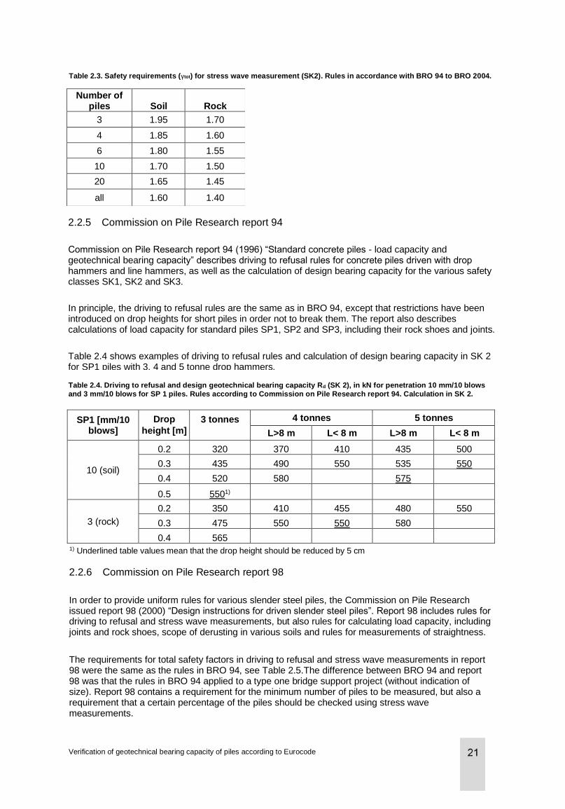
Table 2.3. Safety requirements (γtot) for stress wave measurement (SK2). Rules in accordance with BRO 94 to BRO 2004.
Number of piles Soil Rock
3 1.95 1.70
4 1.85 1.60
6 1.80 1.55
10 1.70 1.50
20 1.65 1.45
all 1.60 1.40
2.2.5 Commission on Pile Research report 94
Commission on Pile Research report 94 (1996) “Standard concrete piles - load capacity and geotechnical bearing capacity” describes driving to refusal rules for concrete piles driven with drop hammers and line hammers, as well as the calculation of design bearing capacity for the various safety classes SK1, SK2 and SK3.
In principle, the driving to refusal rules are the same as in BRO 94, except that restrictions have been introduced on drop heights for short piles in order not to break them. The report also describes calculations of load capacity for standard piles SP1, SP2 and SP3, including their rock shoes and joints.
Table 2.4 shows examples of driving to refusal rules and calculation of design bearing capacity in SK 2 for SP1 piles with 3, 4 and 5 tonne drop hammers.
Table 2.4. Driving to refusal and design geotechnical bearing capacity Rd (SK 2), in kN for penetration 10 mm/10 blows
and 3 mm/10 blows for SP 1 piles. Rules according to Commission on Pile Research report 94. Calculation in SK 2.
SP1 [mm/10 blows]
Drop
height [m]
3 tonnes 4 tonnes 5 tonnes
L>8 m L< 8 m L>8 m L< 8 m
10 (soil)
0.2 320 370 410 435 500
0.3 435 490 550 535 550
0.4 520 580
575
0.5 5501)
3 (rock)
0.2 350 410 455 480 550
0.3 475 550 550 580
0.4 565
1) Underlined table values mean that the drop height should be reduced by 5 cm
2.2.6 Commission on Pile Research report 98
In order to provide uniform rules for various slender steel piles, the Commission on Pile Research issued report 98 (2000) “Design instructions for driven slender steel piles”. Report 98 includes rules for driving to refusal and stress wave measurements, but also rules for calculating load capacity, including joints and rock shoes, scope of derusting in various soils and rules for measurements of straightness.
The requirements for total safety factors in driving to refusal and stress wave measurements in report 98 were the same as the rules in BRO 94, see Table 2.5.The difference between BRO 94 and report 98 was that the rules in BRO 94 applied to a type one bridge support project (without indication of size). Report 98 contains a requirement for the minimum number of piles to be measured, but also a requirement that a certain percentage of the piles should be checked using stress wave measurements.
Verification of geotechnical bearing capacity of piles according to Eurocode
This is in order to get a better statistical picture of possible variations in the pile foundation.
Table 2.5. Requirements for safety factors in accordance with BRO 94 to BRO 2004 and Commission on Pile Research report 98.
Number of
tests per
project
Corresponds
to approx. %
Safety factor requirement
PKR 98; SK 2
Safety factor requirement
BRO 94; SK 2
Report 98 Soil Rock Soil Rock
0 0% 2.3 2.1 2.3 2.1
3 5 %
1.95 1.7
4 10 % 1.85 1.65 1.85 1.6
6
1.8 1.55
10 25 % 1.7 1.5 1.7 1.5
All or measured
piles 100 % 1.6 1.4 1.6 1.4
Since the table in BRO 94 also came to be used for elongated bank pilings, a limit was introduced in BRO 2004 on the size of the project (support) to a maximum of 30 x 30 m2. For larger projects, the project would have to be divided into sub-areas, see BRO 2004.
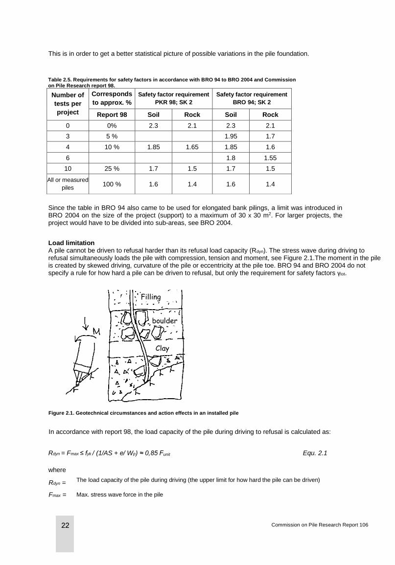
Load limitation A pile cannot be driven to refusal harder than its refusal load capacity (Rdyn). The stress wave during driving to refusal simultaneously loads the pile with compression, tension and moment, see Figure 2.1.The moment in the pile is created by skewed driving, curvature of the pile or eccentricity at the pile toe. BRO 94 and BRO 2004 do not specify a rule for how hard a pile can be driven to refusal, but only the requirement for safety factors γtot.
Figure 2.1. Geotechnical circumstances and action effects in an installed pile
In accordance with report 98, the load capacity of the pile during driving to refusal is calculated as:
Rdyn = Fmax ≤ fyk / (1/AS + e/ Wp) ≈ 0,85 Funit Equ. 2.1
where
Commission on Pile Research Report 106
Rdyn = The load capacity of the pile during driving (the upper limit for how hard the pile can be driven)
Fmax = Max. stress wave force in the pile
Filling
boulder
s
Clay
According to Commission on Pile Research report 98, piling is divided into three methods, which limit the piles’ design geotechnical bearing capacity or design effect of action Sd. The upper limit is governed by the pile’s capacity for driving to refusal, Rdyn, and the safety factor requirements in driving to refusal. Report 98 describes how these levels have been developed.
Division In report 98, piling is divided into three levels (execution classes):
• 2A: Maximum load Sd = 0.3 × Funit, driving to refusal only
• 2B: Maximum load Sd = 0.4 × Funit, stress wave control minimum 10%
• 2C: Maximum load Sd = 0.5 × Funit, stress wave control minimum 25%
The driving to refusal table for concrete piles in accordance with BRO 2004 was calculated with a driving computer simulation (WEAP) for a conservative selection of soil parameters with requirements for a total safety factor γtot = 2.3 according to Table 2.5.The computer calculation of driving to refusal and the selection of soil parameters are described in Commission on Pile Research report 92 (1993).
In corresponding fashion, driving to refusal rules were calculated for RR piles (Rautaruukki piles) in combination with various drop hammers. Driving to refusal tables were included in the type approval (1993) for RR90 to RR220 piles for driving with various drop hammers. Calculations were carried out in the same manner as for concrete piles with the WEAP computer program and with a requirement for a total safety factor γtot = 2.3.
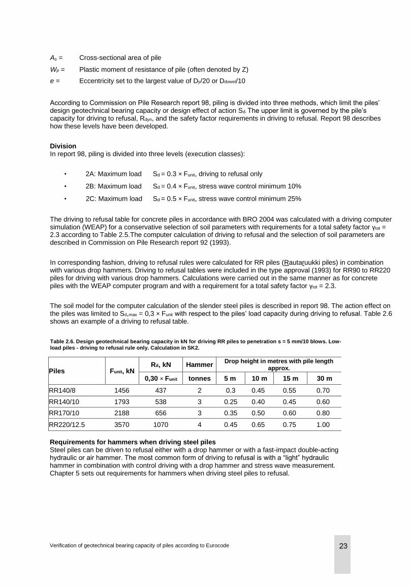
The soil model for the computer calculation of the slender steel piles is described in report 98. The action effect on the piles was limited to Sd,max = 0,3 × Funit with respect to the piles’ load capacity during driving to refusal. Table 2.6 shows an example of a driving to refusal table.
Table 2.6. Design geotechnical bearing capacity in kN for driving RR piles to penetration s = 5 mm/10 blows. Low-
load piles - driving to refusal rule only. Calculation in SK2.
Piles Funit, kN Rd, kN Hammer
Drop height in metres with pile length approx.
0,30 × Funit tonnes 5 m 10 m 15 m 30 m
RR140/8 1456 437 2 0.3 0.45 0.55 0.70
RR140/10 1793 538 3 0.25 0.40 0.45 0.60
RR170/10 2188 656 3 0.35 0.50 0.60 0.80
RR220/12.5 3570 1070 4 0.45 0.65 0.75 1.00
Requirements for hammers when driving steel piles Steel piles can be driven to refusal either with a drop hammer or with a fast-impact double-acting hydraulic or air hammer. The most common form of driving to refusal is with a “light” hydraulic hammer in combination with control driving with a drop hammer and stress wave measurement. Chapter 5 sets out requirements for hammers when driving steel piles to refusal.
Verification of geotechnical bearing capacity of piles according to Eurocode
As = Cross-sectional area of pile
Wp = Plastic moment of resistance of pile (often denoted by Z)
e = Eccentricity set to the largest value of Dy/20 or Ddowel/10
3 Governing documents
3.1 General
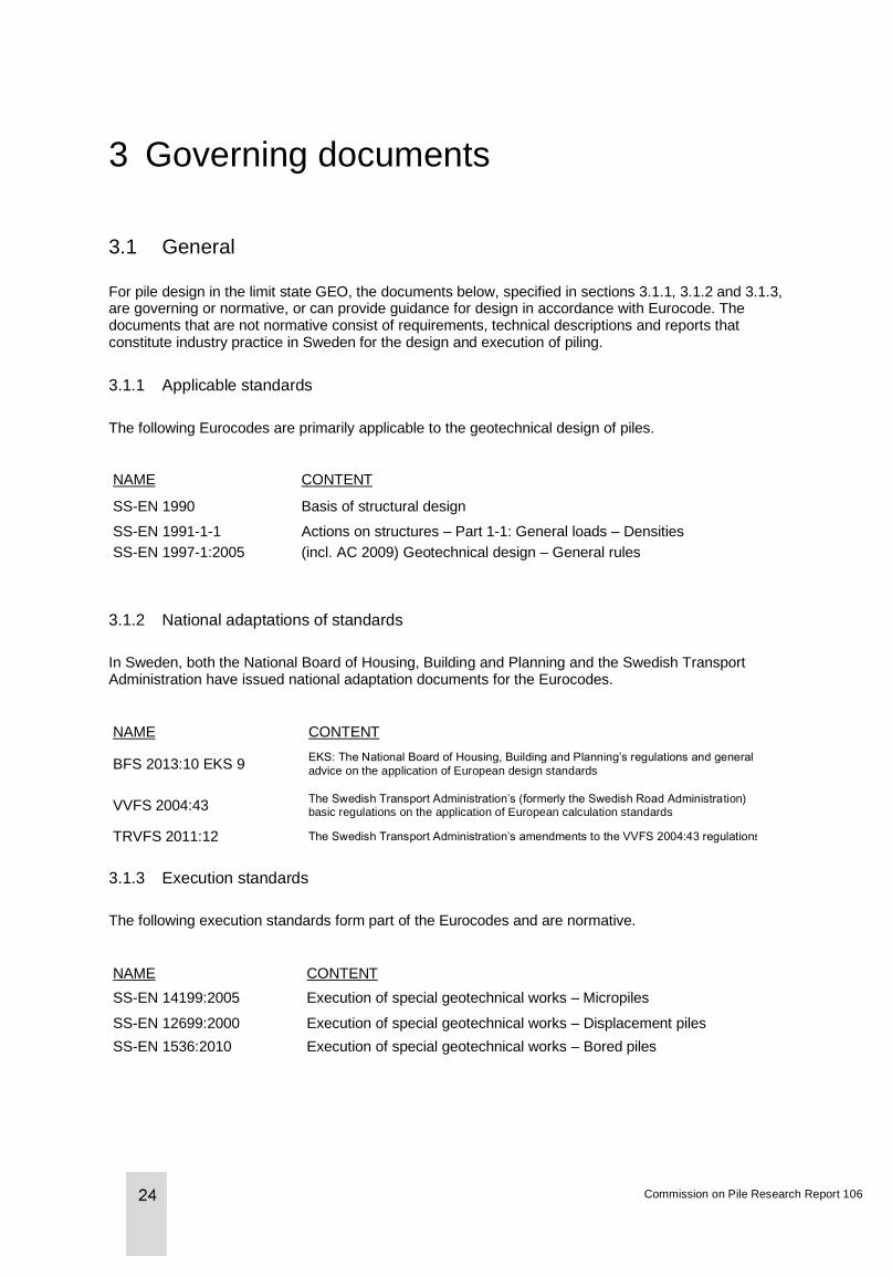
For pile design in the limit state GEO, the documents below, specified in sections 3.1.1, 3.1.2 and 3.1.3, are governing or normative, or can provide guidance for design in accordance with Eurocode. The documents that are not normative consist of requirements, technical descriptions and reports that constitute industry practice in Sweden for the design and execution of piling.
3.1.1 Applicable standards
The following Eurocodes are primarily applicable to the geotechnical design of piles.
NAME CONTENT
SS-EN 1990 Basis of structural design
SS-EN 1991-1-1 Actions on structures – Part 1-1: General loads – Densities
SS-EN 1997-1:2005 (incl. AC 2009) Geotechnical design – General rules
3.1.2 National adaptations of standards
In Sweden, both the National Board of Housing, Building and Planning and the Swedish Transport Administration have issued national adaptation documents for the Eurocodes.
NAME CONTENT
BFS 2013:10 EKS 9 EKS: The National Board of Housing, Building and Planning’s regulations and general
advice on the application of European design standards
VVFS 2004:43 The Swedish Transport Administration’s (formerly the Swedish Road Administration) basic regulations on the application of European calculation standards
TRVFS 2011:12 The Swedish Transport Administration’s amendments to the VVFS 2004:43 regulations
3.1.3 Execution standards
The following execution standards form part of the Eurocodes and are normative.
NAME CONTENT
SS-EN 14199:2005 Execution of special geotechnical works – Micropiles
SS-EN 12699:2000 Execution of special geotechnical works – Displacement piles
SS-EN 1536:2010 Execution of special geotechnical works – Bored piles
Commission on Pile Research Report 106
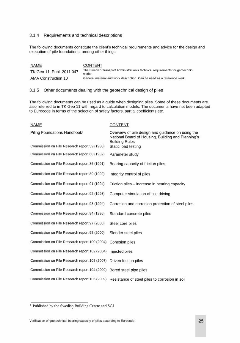
3.1.4 Requirements and technical descriptions
The following documents constitute the client’s technical requirements and advice for the design and execution of pile foundations, among other things.
NAME CONTENT
TK Geo 11, Publ. 2011:047 The Swedish Transport Administration’s technical requirements for geotechnical works
AMA Construction 10 General material and work description. Can be used as a reference work
3.1.5 Other documents dealing with the geotechnical design of piles
The following documents can be used as a guide when designing piles. Some of these documents are also referred to in TK Geo 11 with regard to calculation models. The documents have not been adapted to Eurocode in terms of the selection of safety factors, partial coefficients etc.
NAME CONTENT
Piling Foundations Handbook1 Overview of pile design and guidance on using the National Board of Housing, Building and Planning’s New Building Rules
Commission on Pile Research report 59 (1980) Static load testing
Commission on Pile Research report 68 (1982) Parameter study
Commission on Pile Research report 86 (1991) Bearing capacity of friction piles
Commission on Pile Research report 89 (1992) Integrity control of piles
Commission on Pile Research report 91 (1994) Friction piles – increase in bearing capacity
Commission on Pile Research report 92 (1993) Computer simulation of pile driving
Commission on Pile Research report 93 (1994) Corrosion and corrosion protection of steel piles
Commission on Pile Research report 94 (1996) Standard concrete piles
Commission on Pile Research report 97 (2000) Steel core piles
Commission on Pile Research report 98 (2000) Slender steel piles
Commission on Pile Research report 100 (2004) Cohesion piles
Commission on Pile Research report 102 (2004) Injected piles
Commission on Pile Research report 103 (2007) Driven friction piles
Commission on Pile Research report 104 (2009) Bored steel pipe piles
Commission on Pile Research report 105 (2009) Resistance of steel piles to corrosion in soil
Verification of geotechnical bearing capacity of piles according to Eurocode
1 Published by the Swedish Building Centre and SGI
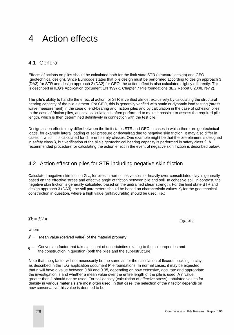
4 Action effects
4.1 General
Effects of actions on piles should be calculated both for the limit state STR (structural design) and GEO (geotechnical design). Since Eurocode states that pile design must be performed according to design approach 3 (DA3) for STR and design approach 2 (DA2) for GEO, the action effect is also calculated slightly differently. This is described in IEG’s Application document EN 1997-1 Chapter 7 Pile foundations (IEG Report 8:2008, rev 2).
The pile’s ability to handle the effect of action for STR is verified almost exclusively by calculating the structural bearing capacity of the pile element. For GEO, this is generally verified with static or dynamic load testing (stress wave measurement) in the case of end-bearing and friction piles and by calculation in the case of cohesion piles. In the case of friction piles, an initial calculation is often performed to make it possible to assess the required pile length, which is then determined definitively in connection with the test pile.
Design action effects may differ between the limit states STR and GEO in cases in which there are geotechnical loads, for example lateral loading of soil pressure or downdrag due to negative skin friction. It may also differ in cases in which it is calculated for different safety classes. One example might be that the pile element is designed in safety class 3, but verification of the pile’s geotechnical bearing capacity is performed in safety class 2. A recommended procedure for calculating the action effect in the event of negative skin friction is described below.
4.2 Action effect on piles for STR including negative skin friction
Calculated negative skin friction Gneg for piles in non-cohesive soils or heavily over-consolidated clay is generally based on the effective stress and effective angle of friction between pile and soil. In cohesive soil, in contrast, the negative skin friction is generally calculated based on the undrained shear strength. For the limit state STR and design approach 3 (DA3), the soil parameters should be based on characteristic values Xk for the geotechnical construction in question, where a high value (unfavourable) should be used, i.e.:
Equ. 4.1
where
Note that the η factor will not necessarily be the same as for the calculation of flexural buckling in clay,
as described in the IEG application document Pile foundations. In normal cases, it may be expected that η will have a value between 0.80 and 0.95, depending on how extensive, accurate and appropriate the investigation is and whether a mean value over the entire length of the pile is used. A η value greater than 1 should not be used. For soil density (calculation of effective stress), tabulated values for density in various materials are most often used. In that case, the selection of the η factor depends on how conservative this value is deemed to be.
Commission on Pile Research Report 106
Mean value (derived value) of the material property
Conversion factor that takes account of uncertainties relating to the soil properties and the construction in question (both the piles and the superstructure)
Xk = X̄ / η
X̄ =
η =
Below there is a simplified load combination in the ultimate limit state (ULS) for structures exposed to geotechnical loads in accordance with equation 6.10 (SS-EN 1990), including negative skin friction, with design values for loads according to the national annexes for the application of European calculation standards/design standards (TRVFS and BFS), set C:
Equ. 4.2
where
Ed,geo = Design geotechnical effect of action
γd = Partial coefficient for safety class
GG = Characteristic value for permanent geotechnical load
Gneg = Characteristic value for downdrag due to negative skin friction
QG = Characteristic value for variable geotechnical load
For a vertical pile exposed only to negative skin friction from an even settlement of the soil, QG and Gg are generally zero, where Gc is the self-weight of the pile down to the neutral layer. These load components may, conversely, be active, e.g. as horizontal (transverse) loads simultaneously with the vertical negative skin friction.
The geotechnical load should then be combined with the structural load according to equation 6.10a (SS-EN 1990), with design values for loads according to TRVFS or BFS, set B:
Equ. 4.3
where
Gk = Characteristic value for permanent structural load
ψ0 = Factor for combination value for variable load
Qk,longterm = Characteristic value for variable long-term load
Transient variable structural loads do not generally need to be included with the negative skin friction. The definition of “transient” depends on how the settlement develops over time. In general, around 3-5 mm relative movement between pile and soil is required in order to mobilise maximum friction. On the part of the pile that is affected by axial downdrag due to negative skin friction, a positive skin friction can be applied for the upper part of the pile’s skin surface for transient loads, i.e. instead of downdrag a contribution to bearing capacity is obtained. Of course, one should check that Equation 6.10 b is not applicable, which will be the case if the transient variable loads are sufficiently large.
Note that safety class 3 should be selected for piles in STR if it is feared that fracture of the piles will result in large movements that may cause the superstructure to collapse, e.g. in the case of flexural bending in piles with a part in the air, water or in very loose soil.
With regard to the effect of negative skin friction in the serviceability limit state (SLS), the load is generally calculated with quasi-permanent1 load combinations using equation 6.16b (SS-EN 1990), which is applied for long-term effects. In the case of concrete piles, the crack width and the edge stress are checked with respect to concrete creep.
Verification of geotechnical bearing capacity of piles according to Eurocode
1 The total time for which the load value will be exceeded represents a large part of the reference period. It is
expressed as part of the characteristic load, ψ2Qk
Ed,geo = γd. 1.1 (GG + Gneg) + γd1.4 QG
Ed = Ed,geo + γd. 1.35 Gk + γd1.5 ψ0 Qk,longterm
The frequent2 load combination, equation 6.15b, is relevant when calculating elastic deformations (reversible limit state) of piles.
For piles, the bearing capacity is also calculated in the serviceability limit state without permitting plastic deformations of either the pile material or in the soil, i.e. the irreversible limit state (permanent deformations) must not be reached. That this is not the case is checked by using characteristic3 load combinations with equation 6.14b. For characteristic load combinations, negative skin friction rarely needs to be included unless the permanent proportion of the load is clearly dominant and the length of the piles in soil prone to settlement is large.
4.3 Action effect on piles for GEO including negative skin friction
Negative skin friction Gneg calculated using the effective angle of friction or undrained shear strength for
the limit state GEO and design approach 2 (DA2) should be based on derived values with respect to
the mean value, X̄. Geotechnical loads are treated in the same way as structural loads. SS-EN 1990,
equation 6.10, set C, is not used.
Since axial load loads and transient variable loads do not generally need to be combined, piles that are not exposed to transverse loads are governed by equation 6.10a. Below there is a simplified load combination in the ultimate limit state (ULS) according to equation 6.10a (SS-EN 1990), including negative skin friction and with design values for loads according to TRVFS or BFS, set B:
Equ. 4.4
where
G = Characteristic value for permanent load (geotechnical load and structural load)
In general, safety class SK2 is used for piles in GEO. However, this does not always apply to cohesion piles if strain-softening behaviour may be expected (progressive fracture mode) after a fracture has occurred. Safety class SK3 should therefore be used if a large number of people will be present in or near the structure at the same time. Note that if there is a large proportion of transient variable loads, equation 6.10bi SS-EN 1990 may apply.
In the serviceability limit state, it is generally the case that long-term settlement is controlled according to the quasi-permanent combination with equation 6.16b in SS-EN 1990. For elastic settlement only, in contrast, equation 6.15b in SS-EN 1990 is applicable.
4.4 Design values for loads
Table 4.1 shows overall design values in the ultimate and serviceability limit states for loads with different load combinations in accordance with SS-EN 1990, with national choices in accordance with BFS 2013:10 EKS 9 and TRVFS 2011:12. For exceptional design situations (accidents or accident situation), Equation 6.11 b applies.
2 The load value will be only exceeded during a small part of the reference period, ψ1Qk 3 The predominantly representative value for a load.
Commission on Pile Research Report 106
Ed = γd. 1.35 (G + Gneg) + γd 1.35 ψ0 Qk,longterm
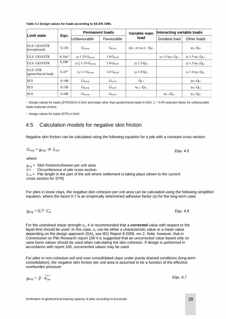
Limit state Equ. Permanent loads Variable main
load
Interacting variable loads
Unfavourable Favourable Greatest load Other loads
ULS: GEO/STR (exceptional)
6.11b Gkj,sup Gkj,inf (ψ1.1 or ψ2.1) ∙Qk,1
ψ2,i∙Qk,i
ULS: GEO/STR 6.10a1) γd∙1.35∙Gkj,sup 1.0∙Gkj,inf γd∙1.5∙ψ0.1∙Qk,1 γd∙1.5∙ψ0,i∙Qk,i
ULS: GEO/STR 6.10b1 γd∙ξ∙1.35∙Gkj,sup 1.0∙Gkj,inf γd∙1.5∙Qk,1 γd∙1.5∙ψ0,i∙Qk,i
ULS: STR (geotechnical load)
6.102’ γd∙1.1∙Gkj,sup 1.0 Gkj,inf γd∙1.4∙Qk,1
γd∙1.4∙ψ0,i∙Qk,i
SLS 6.14b Gkj,sup Gkj,inf Qk,1 ψ0,i∙Qk,i
SLS 6.15b Gkj,sup Gkj,inf ψ1.1 ∙Qk,1 ψ2,i∙Qk,i
SLS 6.16b Gkj,sup Gkj,inf ψ2.1∙Qk,1 ψ2,i∙Qk,i
Table 4.1 Design values for loads according to SS-EN 1990.
1) Design values for loads (STR/GEO) in DA2 and loads other than geotechnical loads in DA3. ξ = 0.89 reduction factor for unfavourable
loads (national choice).
2) Design values for loads (STR) in DA3.
4.5 Calculation models for negative skin friction
Negative skin friction can be calculated using the following equation for a pile with a constant cross section:
Equ. 4.5
where
gneg = Skin friction/cohesion per unit area θ = Circumference of pile cross section Lcur = Pile length in the part of the soil where settlement is taking place (down to the current cross section for STR)
For piles in loose clays, the negative skin cohesion per unit area can be calculated using the following simplified equation, where the factor 0.7 is an empirically determined adhesion factor (α) for the long-term case:
Equ. 4.6
For the undrained shear strength cu, it is recommended that a corrected value with respect to the liquid limit should be used. In this case, cu can be either a characteristic value or a mean value depending on the design approach (DA), see IEG Report 8:2008, rev 2. Note, however, that in Commission on Pile Research report 100 it is suggested that an uncorrected value based only on vane borer values should be used when calculating the skin cohesion. If design is performed in accordance with report 100, uncorrected values may be used.
For piles in non-cohesive soil and over-consolidated clays under purely drained conditions (long-term consolidation), the negative skin friction per unit area is assumed to be a function of the effective overburden pressure:
Equ. 4.7
Verification of geotechnical bearing capacity of piles according to Eurocode
Gneg = gneg · θ · Lact
gneg = 0.7 · Cu
gneg = β · 𝜎𝑣𝑜′̅̅ ̅̅ ̅
For non-cohesive soil, the empirical value β = 0.2 is generally used; this is derived from the product of the soil pressure coefficient Km and the coefficient of friction between the pile and the soil, tan δ'm. A slightly higher value is applicable for clays under long-term conditions and is generally in the order of 0.25 - 0.30. Note that the above method of calculating negative skin friction and considering it as an external load is a simplified procedure. A more correct method is to perform an interaction analysis in which the stiffness of the pile is taken into account and the position of the neutral layer is determined. An interaction analysis is appropriate primarily if the design is performed by calculation and if both positive and negative skin friction occur in the same type of soil layer, or if the settlement relative to the pile is low and is not expected to be fully mobilised in the lower part of the soil layer. The position of the neutral layer should mainly be determined with characteristic loads and derived parameter values in order to be as close as possible to the actual position.
For more information on negative skin friction, please refer to the Piling Foundations Handbook or to Commission on Pile Research report 100 with respect to cohesion piles.
Commission on Pile Research Report 106
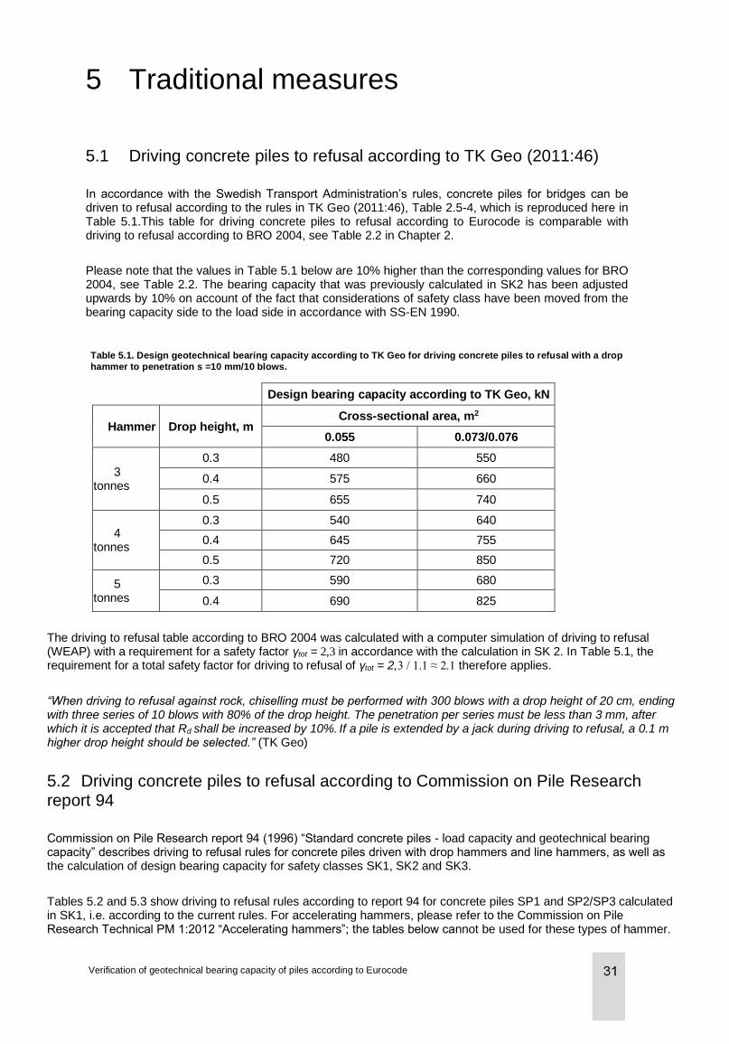
5 Traditional measures
5.1 Driving concrete piles to refusal according to TK Geo (2011:46)
In accordance with the Swedish Transport Administration’s rules, concrete piles for bridges can be driven to refusal according to the rules in TK Geo (2011:46), Table 2.5-4, which is reproduced here in Table 5.1.This table for driving concrete piles to refusal according to Eurocode is comparable with driving to refusal according to BRO 2004, see Table 2.2 in Chapter 2.
Please note that the values in Table 5.1 below are 10% higher than the corresponding values for BRO 2004, see Table 2.2. The bearing capacity that was previously calculated in SK2 has been adjusted upwards by 10% on account of the fact that considerations of safety class have been moved from the bearing capacity side to the load side in accordance with SS-EN 1990.
Table 5.1. Design geotechnical bearing capacity according to TK Geo for driving concrete piles to refusal with a drop
hammer to penetration s =10 mm/10 blows.
Design bearing capacity according to TK Geo, kN
Hammer Drop height, m Cross-sectional area, m2
0.055 0.073/0.076
3 tonnes
0.3 480 550
0.4 575 660
0.5 655 740
4 tonnes
0.3 540 640
0.4 645 755
0.5 720 850
5 tonnes
0.3 590 680
0.4 690 825
The driving to refusal table according to BRO 2004 was calculated with a computer simulation of driving to refusal (WEAP) with a requirement for a safety factor γtot = 2,3 in accordance with the calculation in SK 2. In Table 5.1, the requirement for a total safety factor for driving to refusal of γtot = 2,3 / 1.1 ≈ 2.1 therefore applies.
“When driving to refusal against rock, chiselling must be performed with 300 blows with a drop height of 20 cm, ending with three series of 10 blows with 80% of the drop height. The penetration per series must be less than 3 mm, after which it is accepted that Rd shall be increased by 10%. If a pile is extended by a jack during driving to refusal, a 0.1 m higher drop height should be selected.” (TK Geo)
5.2 Driving concrete piles to refusal according to Commission on Pile Research report 94
Commission on Pile Research report 94 (1996) “Standard concrete piles - load capacity and geotechnical bearing capacity” describes driving to refusal rules for concrete piles driven with drop hammers and line hammers, as well as the calculation of design bearing capacity for safety classes SK1, SK2 and SK3.
Tables 5.2 and 5.3 show driving to refusal rules according to report 94 for concrete piles SP1 and SP2/SP3 calculated in SK1, i.e. according to the current rules. For accelerating hammers, please refer to the Commission on Pile Research Technical PM 1:2012 “Accelerating hammers”; the tables below cannot be used for these types of hammer.
Verification of geotechnical bearing capacity of piles according to Eurocode
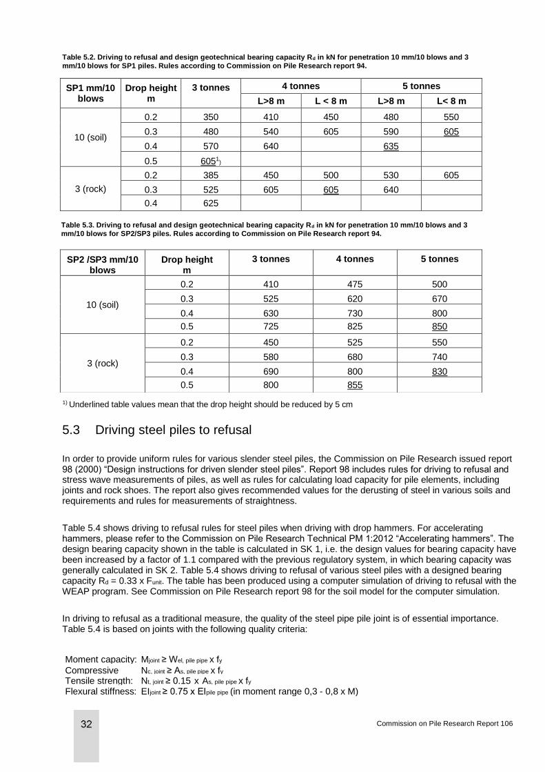
Table 5.2. Driving to refusal and design geotechnical bearing capacity Rd in kN for penetration 10 mm/10 blows and 3
mm/10 blows for SP1 piles. Rules according to Commission on Pile Research report 94.
SP1 mm/10 blows
Drop height m
3 tonnes 4 tonnes 5 tonnes
L>8 m L < 8 m L>8 m L< 8 m
10 (soil)
0.2 350 410 450 480 550
0.3 480 540 605 590 605
0.4 570 640
635
0.5 6051)
3 (rock)
0.2 385 450 500 530 605
0.3 525 605 605 640
0.4 625
Table 5.3. Driving to refusal and design geotechnical bearing capacity Rd in kN for penetration 10 mm/10 blows and 3
mm/10 blows for SP2/SP3 piles. Rules according to Commission on Pile Research report 94.
SP2 /SP3 mm/10 blows
Drop height m
3 tonnes 4 tonnes 5 tonnes
10 (soil)
0.2 410 475 500
0.3 525 620 670
0.4 630 730 800
0.5 725 825 850
3 (rock)
0.2 450 525 550
0.3 580 680 740
0.4 690 800 830
0.5 800 855
1) Underlined table values mean that the drop height should be reduced by 5 cm
5.3 Driving steel piles to refusal
In order to provide uniform rules for various slender steel piles, the Commission on Pile Research issued report 98 (2000) “Design instructions for driven slender steel piles”. Report 98 includes rules for driving to refusal and stress wave measurements of piles, as well as rules for calculating load capacity for pile elements, including joints and rock shoes. The report also gives recommended values for the derusting of steel in various soils and requirements and rules for measurements of straightness.
Table 5.4 shows driving to refusal rules for steel piles when driving with drop hammers. For accelerating hammers, please refer to the Commission on Pile Research Technical PM 1:2012 “Accelerating hammers”. The design bearing capacity shown in the table is calculated in SK 1, i.e. the design values for bearing capacity have been increased by a factor of 1.1 compared with the previous regulatory system, in which bearing capacity was generally calculated in SK 2. Table 5.4 shows driving to refusal of various steel piles with a designed bearing capacity Rd = 0.33 x Funit. The table has been produced using a computer simulation of driving to refusal with the WEAP program. See Commission on Pile Research report 98 for the soil model for the computer simulation.
In driving to refusal as a traditional measure, the quality of the steel pipe pile joint is of essential importance. Table 5.4 is based on joints with the following quality criteria:
Moment capacity: Mjoint ≥ Wel, pile pipe x fy
Compressive strength:
Nc, joint ≥ As, pile pipe x fy
Tensile strength: Nt, joint ≥ 0.15 x As, pile pipe x fy
Flexural stiffness: EIjoint ≥ 0.75 x EIpile pipe (in moment range 0,3 - 0,8 x M)
Commission on Pile Research Report 106
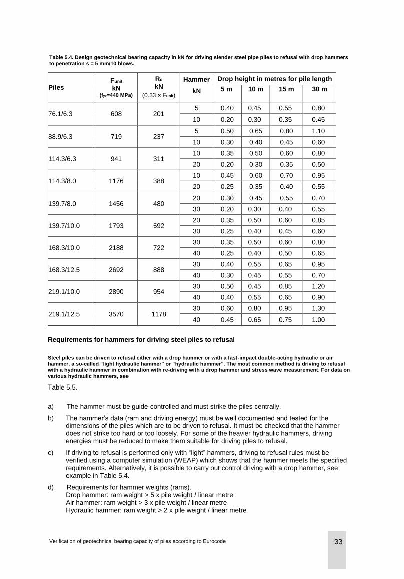
Table 5.4. Design geotechnical bearing capacity in kN for driving slender steel pipe piles to refusal with drop hammers
to penetration s = 5 mm/10 blows.
Piles Funit
kN (fyk=440 MPa)
Rd
kN
(0.33 × Funit)
Hammer
kN
Drop height in metres for pile length
5 m 10 m 15 m 30 m
76.1/6.3 608 201 5 0.40 0.45 0.55 0.80
10 0.20 0.30 0.35 0.45
88.9/6.3 719 237 5 0.50 0.65 0.80 1.10
10 0.30 0.40 0.45 0.60
114.3/6.3 941 311 10 0.35 0.50 0.60 0.80
20 0.20 0.30 0.35 0.50
114.3/8.0 1176 388 10 0.45 0.60 0.70 0.95
20 0.25 0.35 0.40 0.55
139.7/8.0 1456 480 20 0.30 0.45 0.55 0.70
30 0.20 0.30 0.40 0.55
139.7/10.0 1793 592 20 0.35 0.50 0.60 0.85
30 0.25 0.40 0.45 0.60
168.3/10.0 2188 722 30 0.35 0.50 0.60 0.80
40 0.25 0.40 0.50 0.65
168.3/12.5 2692 888 30 0.40 0.55 0.65 0.95
40 0.30 0.45 0.55 0.70
219.1/10.0 2890 954 30 0.50 0.45 0.85 1.20
40 0.40 0.55 0.65 0.90
219.1/12.5 3570 1178 30 0.60 0.80 0.95 1.30
40 0.45 0.65 0.75 1.00
Requirements for hammers for driving steel piles to refusal
Steel piles can be driven to refusal either with a drop hammer or with a fast-impact double-acting hydraulic or air hammer, a so-called “light hydraulic hammer” or “hydraulic hammer”. The most common method is driving to refusal with a hydraulic hammer in combination with re-driving with a drop hammer and stress wave measurement. For data on
various hydraulic hammers, see
Table 5.5.
a) The hammer must be guide-controlled and must strike the piles centrally.
b) The hammer’s data (ram and driving energy) must be well documented and tested for the dimensions of the piles which are to be driven to refusal. It must be checked that the hammer does not strike too hard or too loosely. For some of the heavier hydraulic hammers, driving energies must be reduced to make them suitable for driving piles to refusal.
c) If driving to refusal is performed only with “light” hammers, driving to refusal rules must be verified using a computer simulation (WEAP) which shows that the hammer meets the specified requirements. Alternatively, it is possible to carry out control driving with a drop hammer, see example in Table 5.4.
d) Requirements for hammer weights (rams). Drop hammer: ram weight > 5 x pile weight / linear metre Air hammer: ram weight > 3 x pile weight / linear metre Hydraulic hammer: ram weight > 2 x pile weight / linear metre
Verification of geotechnical bearing capacity of piles according to Eurocode
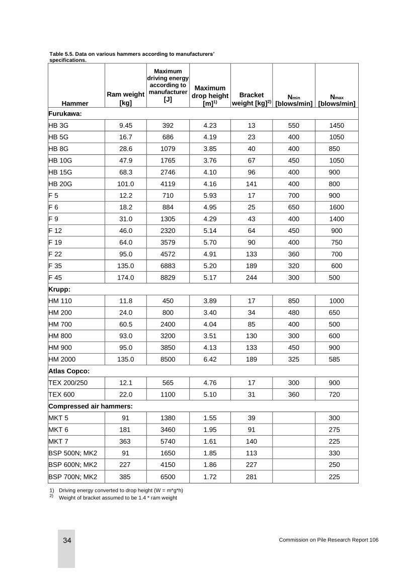
Table 5.5. Data on various hammers according to manufacturers’ specifications.
Hammer
Ram weight
[kg]
Maximum driving energy according to manufacturer
[J]
Maximum drop height
[m]1)
Bracket
weight [kg]2) Nmin
[blows/min] Nmax
[blows/min]
Furukawa:
HB 3G 9.45 392 4.23 13 550 1450
HB 5G 16.7 686 4.19 23 400 1050
HB 8G 28.6 1079 3.85 40 400 850
HB 10G 47.9 1765 3.76 67 450 1050
HB 15G 68.3 2746 4.10 96 400 900
HB 20G 101.0 4119 4.16 141 400 800
F 5 12.2 710 5.93 17 700 900
F 6 18.2 884 4.95 25 650 1600
F 9 31.0 1305 4.29 43 400 1400
F 12 46.0 2320 5.14 64 450 900
F 19 64.0 3579 5.70 90 400 750
F 22 95.0 4572 4.91 133 360 700
F 35 135.0 6883 5.20 189 320 600
F 45 174.0 8829 5.17 244 300 500
Krupp:
HM 110 11.8 450 3.89 17 850 1000
HM 200 24.0 800 3.40 34 480 650
HM 700 60.5 2400 4.04 85 400 500
HM 800 93.0 3200 3.51 130 300 600
HM 900 95.0 3850 4.13 133 450 900
HM 2000 135.0 8500 6.42 189 325 585
Atlas Copco:
TEX 200/250 12.1 565 4.76 17 300 900
TEX 600 22.0 1100 5.10 31 360 720
Compressed air hammers:
MKT 5 91 1380 1.55 39
300
MKT 6 181 3460 1.95 91
275
MKT 7 363 5740 1.61 140
225
BSP 500N; MK2 91 1650 1.85 113
330
BSP 600N; MK2 227 4150 1.86 227
250
BSP 700N; MK2 385 6500 1.72 281
225
1) Driving energy converted to drop height (W = m*g*h) 2) Weight of bracket assumed to be 1.4 * ram weight
Commission on Pile Research Report 106

Drop heights for driving slender steel piles to refusal with drop hammers generally vary between around 0.3 and 1.0 m. In addition to the geotechnical bearing capacity value, the drop height depends entirely on the ratio between the weight of the hammer and the length of the pile. Short piles can be driven to refusal with low drop heights, while long piles require a large drop height.
If the driving energy is converted to drop heights for air and hydraulic hammers, slender steel piles are generally driven to refusal with drop heights corresponding to approx. 1.5 -2.0 m with air hammers and approx. 4-6 m with hydraulic hammers. Steel piles with a diameter from 76 mm to 220 mm can be advantageously driven with light hydraulic hammers with a ram weight 2-3 times the weight of the pile per linear metre. Piles are then re-driven with drop hammers and stress wave measurements are taken to the extent required.
The advantage of driving with light, fast-impact hydraulic hammers is that the driving process is quick and the piles are clearly much straighter than if they are impacted and driven to refusal with drop hammers.
The disadvantage of light hydraulic hammers is that piles can come to a stop in rocky layers. It is important that sufficiently heavy rams are used and that piles are driven to refusal using small penetration values (generally s < 5 mm/minute). In the event of any uncertainty in the pile refusal, control driving must always be carried out with a drop hammer.
For bored piles in rock, as for driven piles in rock, the geotechnical bearing capacity of the piles must be verified by driving to refusal. Requirements for hammer weights are the same as for piles that are impacted and driven to refusal against rock, see point d) above. All piles must be driven to refusal for acceptance.
Verification of geotechnical bearing capacity of piles according to Eurocode
6 Design by calculation
6.1 General
The classical example of design of geotechnical bearing capacity by calculation concerns cohesion piles, which in Sweden are almost exclusively designed using this method. There are, however, also possibilities for designing the geotechnical bearing capacity of other piles with calculation. This applies mainly to friction piles. Other examples of design by calculation include various types of piles under tension, WEAP simulations and calculation of the end-bearing capacity of various piles in soil or rock.
The national adaptation documents for the Eurocodes issued by the National Board of Housing, Building and Planning, BFS 2013:10 EKS 9 and the Swedish Transport Administration, VVFS 2004:43 (basic regulations), with amendments in accordance with TRVFS 2011:12 (see Chapter 3, Governing documents), specify the choice of model factors that apply in Sweden. A good “review” of these can be found in TK Geo 11, Publ. 2011:047, section 2.5.1, including tabulated model factors for various types of piles.
The action effects (GEO) that are to be verified using the calculations described here are shown in Chapter 4, Action effects, in this report.
The model factors in calculations are closely linked to the calculation method and may correlate to a greater or lesser degree with the geotechnical investigations on site. IEG’s TD Piles (IEG Report 8:2008, Rev. 2) presents suggestions for model factors based on the principal type of method, but they must also be linked to the origin of the calculation model.
6.2 Cohesion piles
The bearing capacity of cohesion piles can be verified by testing, for example by means of static load testing in accordance with Commission on Pile Research report 59. In rare cases, dynamic stress wave measurement can be used, but this method is not particularly suitable for cohesion piles and places many requirements on design, execution and evaluation.
For a long time, the predominant method in Sweden has been to design the geotechnical bearing capacity of cohesion piles using calculations. Commission on Pile Research report 100 Cohesion piles is of interest in this regard. Work is currently underway to update this report and bring it into line with Eurocode. Once this work has been completed and published, these new recommendations should, of course, be used.
IEG report 8:2008, rev 2, Application document for EN 1997-1, Chapter 7 Pile foundations (TD Piles) can be used to establish design values. The application document also provides guidelines for how t values for shear strength should be calculated with regard to flexural buckling in clay. Note that the η value applies to calculations of STR in DA3. η values are therefore used when calculating negative skin friction loads, which are combined with action effects in STR for calculating the design/structural bearing capacity of piles at various levels, but not when calculating negative skin friction loads for checking the geotechnical bearing capacity in GEO. Please also note that SS-EN 1997-1, section 7.6.2.3, states that the design can be performed using a so-called model pile analogy, which is not the same approach as in Commission on Pile Research report 100. It does not, however, make any difference whether the calculations are based on the results of individual geotechnical investigations, which are then taken into consideration and reduced to a design value with correlation coefficients and partial coefficients (model pile analogy), or whether the engineer, using his/her geotechnical skills and all the available knowledge, first considers the results of the various geotechnical investigations and then performs one calculation, taking into account the correct reduction factors in accordance with table A.10 in SS-EN 1997-1, which are based on the quantity of investigations.
Commission on Pile Research Report 106
No national choice has been made with regard to these correction factors, either in TRVFS or BFS. The table is also shown in IEG report 8:2008 (TD Piles), table 4.1. The latter approach may be regarded as Swedish practice and is, for example, in line with the recommendations of the Swedish Landslide Risk Commission and SGF Note 4:2005 as to how the evaluation should be performed. Please note that SGF Note 4:2005 is an examination of the guidelines on how we should apply Eurocode and that in that respect it is out of date.
For the undrained shear strength, cu, it is recommended that a corrected value with respect to the liquid limit should be used in index tests, e.g. vane borer, cone test and CPT. In this case, cu can be either a characteristic value or a derived mean value, depending on the design approach (DA), see IEG Report 8:2008, rev 2. Note that a derived value does not necessarily mean it has been corrected. Please also note that in Commission on Pile Research report 100 it is suggested that an uncorrected value based only on vane borer values should be used for the calculation of skin cohesion. If instead one chooses a corrected value for that calculation model, based on several sounding methods, then one must also consider whether to adjust the model factor.
6.3 Friction piles
Commission on Pile Research report 103, Driven friction piles, includes guidelines and methods for calculating the geotechnical bearing capacity of friction piles, specifically prefabricated driven displacement piles. IEG report 8:2008, rev 2, Application document for EN 1997-1, Chapter 7 Pile foundations (TD Piles), is used to establish design values. The use of the model pile analogy is also applicable to friction piles. Here again, one can argue in favour of making an overall compilation of the geotechnical parameters, see above. In such a procedure, however, one should be aware that a friction pile may often have a relatively high bearing capacity at the toe, something which is disregarded in the case of cohesion piles, so that relatively thin layers and highly local variations can significantly affect the overall bearing capacity. In this way, the design can be performed by means of calculation, but the total safety level in accordance with Eurocode for such a procedure will be high. This is on account of the relatively large variations in the calculation results, resulting from both the calculation method and the geology. With a calculation procedure, it should therefore be taken into account that different calculation methods produce results of varying degrees of reliability, which is clear from Commission on Pile Research reports 86 Bearing capacity of friction piles and 103 Driven friction piles. It must be concluded that different model factors should therefore be applied, depending on the calculation method used. Indirectly, this also means that there will be different model factors for different geotechnical data, i.e. the methods that display the least variation and errors in the results are based on CPT soundings, e.g. the LCPC or ICP method, which produce the most accurate geotechnical results. This is also apparent in TD Piles, Table 4.3.
A procedure that includes only calculation of the geotechnical bearing capacity thus often leads to an excessively expensive end product. For this reason, a procedure is generally used in which the verification is performed with stress wave measurement and subsequent signal matching with CAPWAP analysis. A less common method is verification with static load testing.
Calculation of the geotechnical bearing capacity of friction piles is not uninteresting; on the contrary, it is important to have a relatively clear picture of what pile lengths can be expected in a project before the test piling begins, not least for the purpose of estimating the costs. These calculations are used to determine characteristic values for the geotechnical bearing capacity.
6.4 Steel core piles
Commission on Pile Research report 97, Steel core piles, Chapter 4.4, contains instructions for calculating the geotechnical bearing capacity of both end-bearing and skin friction (in rock) steel core piles. Design values are established with the aid of IEG report 8:2008, rev 2, Application document for EN 1997-1, Chapter 7 Pile foundations (TD Piles). The model pile analogy is not applicable here, but a complementary approach is used instead, with extra model factors, see also TK Geo 11 2.5.1.5.
Verification of geotechnical bearing capacity of piles according to Eurocode
The geotechnical bearing capacity of various steel core piles, end-bearing and skin friction, under compression and tension, can be calculated in accordance with Commission on Pile Research report 97, section 4.4 Geotechnical bearing capacity. This describes how to calculate the bearing capacity of a end-bearing steel core pile in rock and the bearing capacity of a skin friction core, cast in rock.
For compression-loaded steel core piles, the geotechnical bearing capacity is nowadays generally verified using stress wave measurement; this mainly applies to end-bearing steel cores. The measurements are performed when the steel core has not yet been cast. It may also be acceptable to verify the compression load with tensile testing, which of course requires that the steel core should be of the skin friction type. In order to calculate the required casting length in rock for this type of pile, adhesion calculations should be performed at the interface between the steel and the concrete and between the concrete and the rock surface, see also sections 4.4.2.1 and 4.4.2.2 in Commission on Pile Research report 97. The tensile test can then be performed as a static load test. Stress wave measurements can also be carried out on skin friction compression-loaded steel core piles. Evaluation is performed using the so-called wave-up method. Damage/cracking of the upper parts of the concrete in the casting must be taken into account. In both cases, it is important that the core is only affixed in the rock when the tests are performed, as it is the adhesion to the rock that needs to be tested. Either only the rock borehole is cast again around the core before the test, or the core must be free of the concrete in the casing, which can be achieved, for example, using Denso tape.
In the case of steel cores under tension, these are of course skin friction piles and the casting length must also be calculated as above. In addition, calculations should be performed for a fracture body in rock, in accordance with section 4.4.3. In the Norwegian Pile Guide 2012, chapter 7.7.1, there is a section “Demolition of rock body” which deals with this issue. The appearance of the rock cone is the same, but in the Pile Guide shear and friction along the outside of the rock cone are also permitted. The contribution of shear and friction in the cracking zones must be evaluated in each individual case. Note that in cases in which it is expected that the steel cores will be subjected to simultaneous tensile loading, the rock cones may overlap, especially if the cores are close together. The calculation of the design rock body can then quickly become very awkward and the cores may have to be made considerably longer than originally intended. Tensile load testing to verify this fracture mode is difficult to perform, as the dolly must be set up so far from the core itself that the rock cone, with any overlying interacting soil, is not loaded. In practice, no such tests are performed.
6.5 Injected piles
Commission on Pile Research report 102, Injected piles, chapter 4.4, deals with the geotechnical bearing capacity of injected piles. Once again, it is neither interesting nor desirable to design these piles only by means of calculation. Section 4.4.3 of the report recommends static load testing for the verification of geotechnical bearing capacity. This can often be performed conservatively as a tensile test. With injected piles, one needs to be aware of the issue of buckling, as these piles can be slender. If piles are only placed under tension, it is possible, in spite of a demonstrated geotechnical bearing capacity, to overlook the fact that the piles would have fractured in the event of the compression load to which the piles will be exposed in the permanent phase. Verification by dynamic load testing (stress wave measurement) has also been performed, but one should be aware that the pile will always be damaged. It is therefore recommended that this form of testing should only be performed on piles that will not be included in the load-bearing structure.
6.6 Piles under tension
The Commission on Pile Research Reports 100 and 103 contain sections on the calculation of geotechnical bearing capacity in tension piles. Note that η values for soil parameters may differ from those used for piles under compression. In TK Geo 2.5.1.3, the reduction factor μ is stated to be 1.0 for skin friction piles with a constant cross-section in cohesive soil and 0.7 - 0.9 in non-cohesive soil. μ factor = 0.7 should be used for piles in non-cohesive soil, where the bearing capacity is based on measured or calculated bearing capacity under compressive load and if no analysis is performed.
Commission on Pile Research Report 106
Commission on Pile Research report 97 Steel core piles, section 4.4.3, and TK Geo, section 2.5.1.3.1, contain calculations of the geotechnical bearing capacity of skin friction steel core piles. TK Geo complements the Swedish Transport Administration’s supplement.
6.7 Driving simulation
Driving simulation in the form of WEAP analysis is used to develop a design refusal criterion and is to be regarded as design by calculation. The method is therefore not used in test piling to determine the bearing capacity. The refusal criterion is used as a production control on all piles. Commission on Pile Research report 92 deals with the computer simulation of pile driving. According to Eurocode and the national choices, the design of geotechnical bearing capacity using WEAP analysis alone is permitted only for purely end-bearing piles; in that case, a model factor of 1.3 is applied. The simulation is, however, a useful tool for deciding on the correct driving equipment, optimising the installation phase, checking the compressive and tensile stresses in the pile during driving (see below) and, in the same way as for calculations of friction piles, for giving an indication of pile length.
As with stress wave measurement, when refusal criteria are determined using driving simulation the bearing capacity must be limited with respect to the strength of the pile material. Rd,max is calculated using equations 6.1 and 6.2, which represents a supplementary approach in accordance with SS-EN 1997-1, see also application document Pile foundations (TD Piles):
Equ. 6.1
Equ. 6.2
where:
Rk = Assumed characteristic bearing capacity (a “carefully” evaluated mean value) without excessively high stresses being generated in the pile
γt= Partial coefficient for bearing capacity according to Table A.7-A.9 in TRVFS or Table I-7 - I-9 in BFS, see also Table 7.1 - Table 7.3 below
γRd = Model factor, at least 1.3 for end-bearing piles on rock/hard till in accordance with TK Geo 11 and BFS 2013:10 EKS 9. If the pile is simulated with driving to refusal on rock with less than 3 mm/10 blows, and the pile is bored in rock and driven to refusal with a hammer > 2 times the pile weight/linear metre, it is suggested that a factor of 1.1 can be used. In that case, a Swedish Transport Administration project will use γtot = 1.2 x 1.1 x 1.4 = 1.85 and a National Board of Housing, Building and Planning project γtot = 1.3 × 1.1 × 1.4 = 2.00.
The stresses in the pile can also be determined from the driving simulation. Rk is chosen in such a way that a good margin is obtained for Funit. For drop hammers, higher stresses than 0.8 fyk for steel and 0.7
fcck for concrete should not be used. If accelerating hammers are used for driving to refusal without continuous measurement of applied energy1, these values should be reduced by 0.10. Note that all piles must be driven to refusal with a hammer weight corresponding to at least 2 times the weight of the pile per metre.
Chapter 8.1 specifies how the calculation of geotechnical bearing capacity can be performed for piles that are bored in rock or that stand on rock or hard till.
1 e.g. by registering the hammer’s impact speed
Verification of geotechnical bearing capacity of piles according to Eurocode
Rd,max =Rk
𝛾𝑡𝑜𝑡
γtot = γt·γRd·1.4
7 Design by testing
7.1 General
Test piling is performed before the production stage or at the start of production, in order to evaluate driving and refusal criteria, to suggest or establish a control plan and, where applicable, to select the appropriate piling method. Test piling generally includes the initial piles in each control object and is used as a basis for determining design bearing capacity. In the case of large piling works or in complex conditions, it is recommended that test piling should be carried out well in advance of production in order to obtain a good basis for the tender documentation. Test piling should generally be performed well in advance of production under the following conditions:
• soil with boulders/sloping rock (selection of piling method)
• stubborn layers of hard till (false refusal, increase in bearing capacity, driving depth)
• non-cohesive soil (increase in bearing capacity, compaction effects for pile groups)
• environmental impact (vibrations, pore pressure, mass movements etc.)
In Sweden, a practice has been developed in recent years for projects with driven end-bearing piles in which the piling conditions are well known (geotechnical conditions, pile and driving equipment). In these projects, dynamic testing is generally performed continuously or on individual occasions during the production phase. During progress of the work, the geotechnical designer responsible for the piling must, in consultation with person responsible for measurements, decide whether any production control is necessary on account of deviations or changes in conditions.
With regard to stress wave measurement, there is generally no reason to conduct load testing on the production piles with a force smaller than that for the piles in the pile testing. This means that the production piles can also be used as a basis in the design in order to reduce the correlation coefficient (safety factor). It is therefore possible to drive the piles to refusal with a less stringent criterion or to reduce the length of the piles in soil continuously during the production phase.
Section 7.5.3(1) of EN 1997-1 has been implemented as a regulation in TRVFS 2011:12 and BFS 2013:10 EKS 9. This specifies that dynamic load testing is assumed to be calibrated against static load testing for the same pile type, with similar lengths and cross sections and similar ground conditions. Dynamic load tests may be considered to be sufficiently reliable and correlated with static load tests for the following pile types and conditions:
• Driven steel and concrete piles (precast), which are mainly end-bearing on rock or non-cohesive soil (hard till)
• Prefabricated skin friction piles in non-cohesive soil (friction piles) together with CAPWAP analysis
• Steel core piles and bored steel pipe piles, end-bearing on rock (or hard till)
• Skin friction steel core piles cast in rock evaluated by assessing the upward impact force (wave-up method) at the top level of the grout. This method applies when the grout is intact. Static load testing should be performed when there is an indication of poor grouting
Various international articles may be used as a reference for the correlation between static and dynamic load testing of prefabricated piles, e.g. “CAPWAP correlation studies” by G Likins et al. (1996).
Commission on Pile Research Report 106
For the following pile types and conditions, however, a correlation with static load testing is recommended for the actual conditions on site:
• Cohesion piles
• End-bearing piles on clay till and certain sedimentary rock types
• Fully or partially skin friction piles cast in-situ, bored piles
• Bored and injected piles, MAI, TITAN piles
• Driven injected piles, e.g. Soilex, Franki
7.2 Test piling, design and quantity
National choices of partial coefficients and correlation coefficients for the load testing of piles may be found in the National Board of Housing, Building and Planning’s BFS 2013:10 EKS 9, tables I-7 to I-11 and in the Swedish Transport Administration’s TRVFS 2011:12, tables A.6 - A.9 and A.11. These tables are also shown below in section 7.6.
If static load testing is performed, at least two piles should be tested in order to obtain a basis for design. In accordance with SS-EN 1997-1, however, it is permitted to perform only one test. Testing only one or two piles obviously presupposes that one has a good overview of the geotechnical conditions and that the area for which the piles are to be representative is limited in size and that there are only minor variations in geological, geotechnical and geometric conditions. In BFS, TRVFS and AMA Construction 10, the distance between tested piles within an area defined as a control object may not exceed 25 m. Static load testing can be used advantageously together with dynamic load testing to verify the results and to select input parameters.
If dynamic load testing (stress wave measurement) is performed as a basis for design, at least four piles must normally be measured in accordance with TRVFS and BFS. If the distance between piles within a control object is less than 25 m, it is acceptable that three test piles are measured. It is, however, recommended that at least three piles should always be measured within an area corresponding to 25 x 25 m2. The number of piles to be included in the determination of design values should constitute a representative basis with respect to the installation method, pile function and soil conditions at the site in question. The piles should be evenly distributed over the area or located in areas in which the worst geotechnical conditions with respect to piling may be anticipated. In TRVFS and BFS, the term “uniform geotechnical conditions” is used. Given that the properties of the soil can vary significantly, it is recommended that the distance between piles within a control object should not be too great. This report suggests that the area of a control object should not exceed 25 x 25 m2, which corresponds to approximately one test pile per 200 m2, but in some cases a distance of as little as 10 - 15 m between test piles may be required in order to uncover the varying geotechnical conditions on site. If a group effect is deemed to be of decisive importance, piles may even need to be driven in groups in order to evaluate their bearing capacity and mode of action. If the soil is rocky/full of boulders and there is a large variation in refusal levels and penetration values or there is an increased risk of damage to the pile, these cases are not to be regarded as representing uniform conditions and a larger scope of measurements should therefore be chosen.
It is not easy to give recommendations on the appropriate number of piles that should be tested, as this is strongly dependent on the geotechnical conditions at the site in question. The evaluation of load testing and design, as well as the selection of the number of representative piles, must always be carried out by personnel with suitable geotechnical qualifications and experience. If there is deemed to be a significant level of variation on site, it may be necessary to expand the test piling so that there are a sufficient number of representative piles to evaluate the design geotechnical bearing capacity. Suitable production control can then be carried out to verify the result during test piling and to concentrate the number of test points. In some cases, the production piling itself may give rise to changed conditions which can lead to production control, e.g. compaction of soil, elevated pore pressure, mass displacement and ground heave.
Sometimes, different methods are used in projects to determine bearing capacity. This most commonly takes the form of stress wave measurement being performed with the CASE method and then signal matching (CAPWAP analysis) being carried out on some of the piles evaluated with CASE in order to correlate the methods.
Verification of geotechnical bearing capacity of piles according to Eurocode
If a good correlation is obtained, the other piles evaluated with the CASE method can then use the lower model factor for CAPWAP. Put simply, it may be said that the CASE method is upgraded to CAPWAP analysis.
When dynamic testing is performed on end-bearing steel piles with low skin resistance that are driven to refusal on good rock where the bearing capacity is not mobilised (i.e. a penetration of < approx. 1 mm per blow), in principle the measured bearing capacity is proportional to the pile’s cross-sectional area (impedance). In such cases, piles with different cross-sectional areas may be included in the same data for the evaluation of design bearing capacity. The calculation of design bearing capacity for each pile dimension is carried out proportionally with respect to the ratio between the cross-sectional areas for the relevant pile types. The assessment that there is a sufficiently good correlation between piles of different cross-sectional area may, however, only be made by qualified personnel in connection with the evaluation of the results. The results should be verified for some of the production piles, see Chapter 9.
7.3 Evaluation of bearing capacity with static load testing
Eurocode states that a settlement should be selected for the pile top that corresponds to 10% of the pile diameter as a failure criterion if it is difficult to evaluate a clear fracture on account of a continuous curvature of the load/settlement curve, which is especially common in piles in non-cohesive soil with strain-hardening behaviour. However, it is not particularly appropriate to select this as a general failure criterion. Firstly, measuring the settlement for the pile top means that the pile’s own elastic compression is not taken into account, which can be significant for long and slender piles. Secondly, the criterion for piles with a large diameter, e.g. bored piles with a diameter of 1-2 m, entails a risk of large settlement differences for which the superstructure is not designed. Instead, it is recommended that the failure criterion should be chosen with regard to the settlement that the superstructure can withstand in the ultimate limit state.
The Piling Foundations Handbook describes various methods for performing static load testing. In addition, it describes how fracture load is evaluated according to the creep method or the Commission on Pile Research’s conventional method in accordance with report 59, in which recommendations are given on how static load testing should be performed. Note that stress wave measurements where the bearing capacity has been determined using the CASE method or CAPWAP analysis are methods that are correlated with static load testing evaluated with Davison’s failure criterion, which is a relatively conservative criterion. This method is described in Commission on Pile Research report 103. The creep method is also conservative if the superstructure cannot handle large movement differences in the ultimate limit state. There are other methods that are also worth mentioning, including Chin’s method, which is often described in international literature, e.g. by Tomlinson (2008).
The Eurocode’s execution instructions for piling work (micropiles, bored piles and displacement piles) specify that load testing must be carried out in accordance with EN 1997-1 and ISO 22477-1 to 2 (currently only available in draft form). In addition, the test piling report must be in accordance with the instructions in SS EN 1997-1. IEG report 4:2008, Document management, also describes what a test report should contain.
7.4 Evaluation of bearing capacity with dynamic load testing
The CASE method actually consists of a mathematical formula for calculating the bearing capacity of end-bearing piles from the input stress wave and the reflection from the toe. In this method, both the dynamic and static bearing capacity are calculated based on empirical data. The static part is calculated using an empirically correlated damping factor (JC, CASE damping factor), which is assumed to be linearly proportional to the particle velocity at the toe. The damping factor is correlated with static load testing. As the damping factor is uncertain for piles with high skin friction resistance, a CAPWAP analysis should be performed. CAPWAP analysis is a method based on one-dimensional wave theory, in which the pile is divided into discrete elements of masses and springs. The action of the surrounding soil is divided into discrete points (element boundaries), which affect the pile in the form of quake, damping and bearing capacity. The measured stress waves are then used as input data from which a simplified model of interaction between the soil and the pile is generated. If the pile is on rock or very hard till, the selection of the CASE damping factor has little or no effect on the bearing capacity.
Commission on Pile Research Report 106
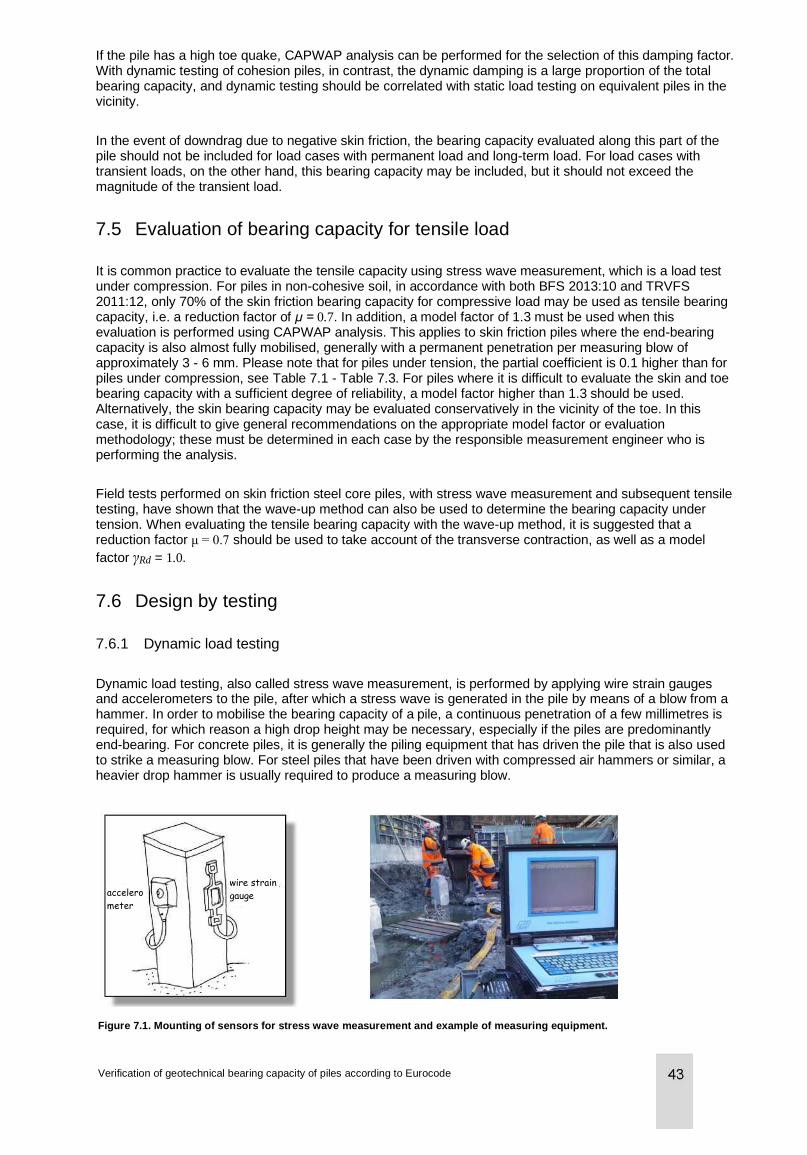
If the pile has a high toe quake, CAPWAP analysis can be performed for the selection of this damping factor. With dynamic testing of cohesion piles, in contrast, the dynamic damping is a large proportion of the total bearing capacity, and dynamic testing should be correlated with static load testing on equivalent piles in the vicinity.
In the event of downdrag due to negative skin friction, the bearing capacity evaluated along this part of the pile should not be included for load cases with permanent load and long-term load. For load cases with transient loads, on the other hand, this bearing capacity may be included, but it should not exceed the magnitude of the transient load.
7.5 Evaluation of bearing capacity for tensile load
It is common practice to evaluate the tensile capacity using stress wave measurement, which is a load test under compression. For piles in non-cohesive soil, in accordance with both BFS 2013:10 and TRVFS 2011:12, only 70% of the skin friction bearing capacity for compressive load may be used as tensile bearing capacity, i.e. a reduction factor of μ = 0.7. In addition, a model factor of 1.3 must be used when this evaluation is performed using CAPWAP analysis. This applies to skin friction piles where the end-bearing capacity is also almost fully mobilised, generally with a permanent penetration per measuring blow of approximately 3 - 6 mm. Please note that for piles under tension, the partial coefficient is 0.1 higher than for piles under compression, see Table 7.1 - Table 7.3. For piles where it is difficult to evaluate the skin and toe bearing capacity with a sufficient degree of reliability, a model factor higher than 1.3 should be used. Alternatively, the skin bearing capacity may be evaluated conservatively in the vicinity of the toe. In this case, it is difficult to give general recommendations on the appropriate model factor or evaluation methodology; these must be determined in each case by the responsible measurement engineer who is performing the analysis.
Field tests performed on skin friction steel core piles, with stress wave measurement and subsequent tensile testing, have shown that the wave-up method can also be used to determine the bearing capacity under tension. When evaluating the tensile bearing capacity with the wave-up method, it is suggested that a reduction factor μ = 0.7 should be used to take account of the transverse contraction, as well as a model
factor γRd = 1.0.
7.6 Design by testing
7.6.1 Dynamic load testing
Dynamic load testing, also called stress wave measurement, is performed by applying wire strain gauges and accelerometers to the pile, after which a stress wave is generated in the pile by means of a blow from a hammer. In order to mobilise the bearing capacity of a pile, a continuous penetration of a few millimetres is required, for which reason a high drop height may be necessary, especially if the piles are predominantly end-bearing. For concrete piles, it is generally the piling equipment that has driven the pile that is also used to strike a measuring blow. For steel piles that have been driven with compressed air hammers or similar, a heavier drop hammer is usually required to produce a measuring blow.
Figure 7.1. Mounting of sensors for stress wave measurement and example of measuring equipment.
Verification of geotechnical bearing capacity of piles according to Eurocode
accelero
meter
wire strain
gauge
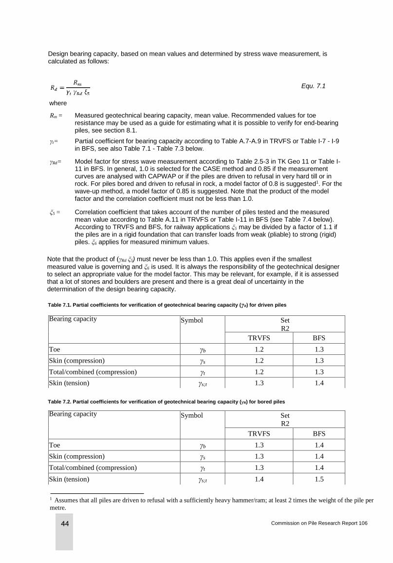
Design bearing capacity, based on mean values and determined by stress wave measurement, is calculated as follows:
Equ. 7.1
where
Rm = Measured geotechnical bearing capacity, mean value. Recommended values for toe resistance may be used as a guide for estimating what it is possible to verify for end-bearing piles, see section 8.1.
γt= Partial coefficient for bearing capacity according to Table A.7-A.9 in TRVFS or Table I-7 - I-9 in BFS, see also Table 7.1 - Table 7.3 below.
γRd= Model factor for stress wave measurement according to Table 2.5-3 in TK Geo 11 or Table I-11 in BFS. In general, 1.0 is selected for the CASE method and 0.85 if the measurement curves are analysed with CAPWAP or if the piles are driven to refusal in very hard till or in rock. For piles bored and driven to refusal in rock, a model factor of 0.8 is suggested1. For the wave-up method, a model factor of 0.85 is suggested. Note that the product of the model factor and the correlation coefficient must not be less than 1.0.
ξ5 = Correlation coefficient that takes account of the number of piles tested and the measured mean value according to Table A.11 in TRVFS or Table I-11 in BFS (see Table 7.4 below). According to TRVFS and BFS, for railway applications ξ5 may be divided by a factor of 1.1 if the piles are in a rigid foundation that can transfer loads from weak (pliable) to strong (rigid) piles. ξ6 applies for measured minimum values.
Note that the product of (γRd ξ5) must never be less than 1.0. This applies even if the smallest measured value is governing and ξ6 is used. It is always the responsibility of the geotechnical designer to select an appropriate value for the model factor. This may be relevant, for example, if it is assessed that a lot of stones and boulders are present and there is a great deal of uncertainty in the determination of the design bearing capacity.
Table 7.1. Partial coefficients for verification of geotechnical bearing capacity (γR) for driven piles
Bearing capacity Symbol Set R2
TRVFS BFS
Toe γb 1.2 1.3
Skin (compression) γs 1.2 1.3
Total/combined (compression) γt 1.2 1.3
Skin (tension) γs;t 1.3 1.4
Table 7.2. Partial coefficients for verification of geotechnical bearing capacity (yR) for bored piles
Bearing capacity Symbol Set R2
TRVFS BFS
Toe γb 1.3 1.4
Skin (compression) γs 1.3 1.4
Total/combined (compression) γt 1.3 1.4
Skin (tension) γs;t 1.4 1.5
Commission on Pile Research Report 106
1 Assumes that all piles are driven to refusal with a sufficiently heavy hammer/ram; at least 2 times the weight of the pile per
metre.
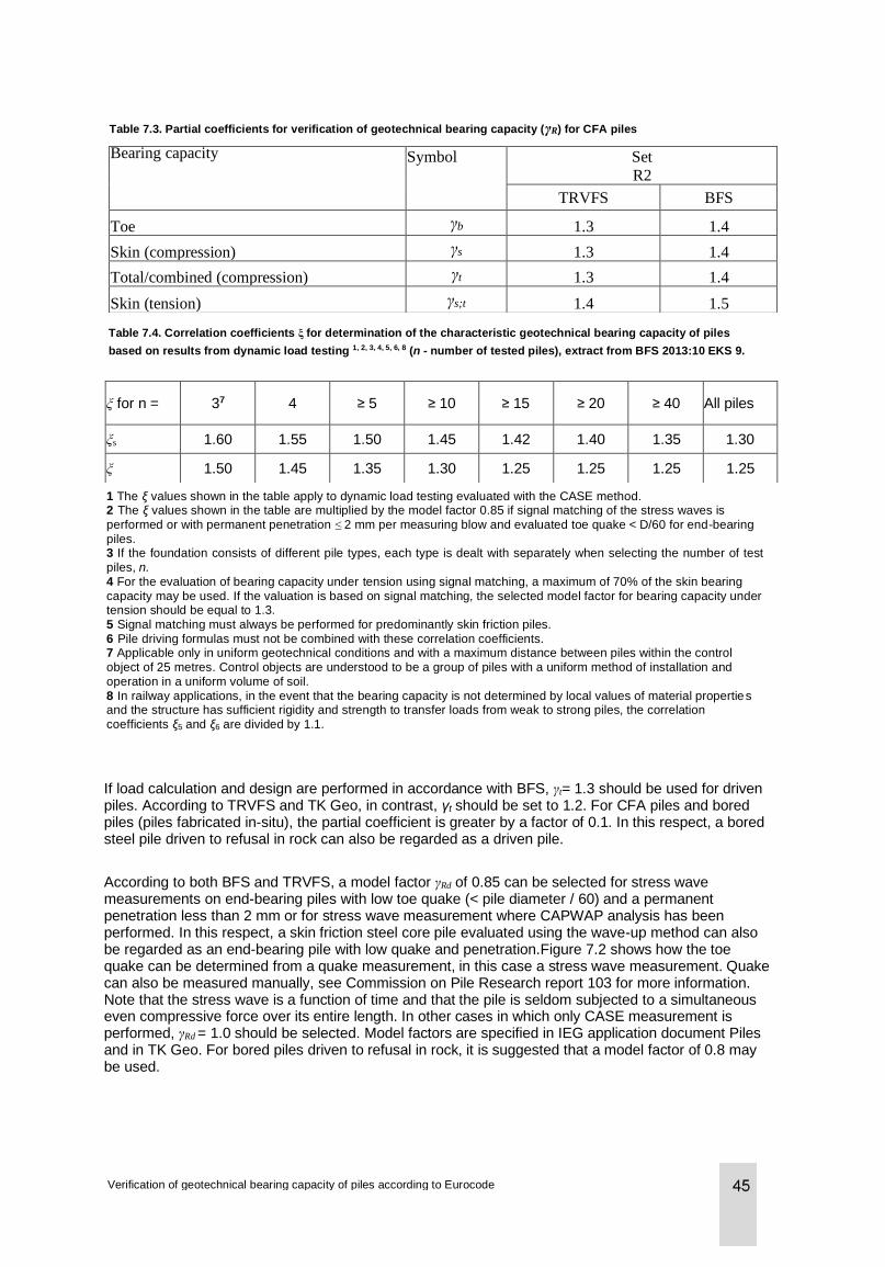
Table 7.3. Partial coefficients for verification of geotechnical bearing capacity (γR) for CFA piles
Bearing capacity Symbol Set R2
TRVFS BFS
Toe γb 1.3 1.4
Skin (compression) γs 1.3 1.4
Total/combined (compression) γt 1.3 1.4
Skin (tension) γs;t 1.4 1.5
Table 7.4. Correlation coefficients ξ for determination of the characteristic geotechnical bearing capacity of piles
based on results from dynamic load testing 1, 2, 3, 4, 5, 6, 8 (n - number of tested piles), extract from BFS 2013:10 EKS 9.
ξ for n = 37 4 ≥ 5 ≥ 10 ≥ 15 ≥ 20 ≥ 40 All piles
ξs 1.60 1.55 1.50 1.45 1.42 1.40 1.35 1.30
ξ 1.50 1.45 1.35 1.30 1.25 1.25 1.25 1.25
1 The ξ values shown in the table apply to dynamic load testing evaluated with the CASE method. 2 The ξ values shown in the table are multiplied by the model factor 0.85 if signal matching of the stress waves is performed or with permanent penetration ≤ 2 mm per measuring blow and evaluated toe quake < D/60 for end-bearing piles. 3 If the foundation consists of different pile types, each type is dealt with separately when selecting the number of test piles, n. 4 For the evaluation of bearing capacity under tension using signal matching, a maximum of 70% of the skin bearing capacity may be used. If the valuation is based on signal matching, the selected model factor for bearing capacity under tension should be equal to 1.3. 5 Signal matching must always be performed for predominantly skin friction piles. 6 Pile driving formulas must not be combined with these correlation coefficients. 7 Applicable only in uniform geotechnical conditions and with a maximum distance between piles within the control object of 25 metres. Control objects are understood to be a group of piles with a uniform method of installation and operation in a uniform volume of soil. 8 In railway applications, in the event that the bearing capacity is not determined by local values of material properties and the structure has sufficient rigidity and strength to transfer loads from weak to strong piles, the correlation coefficients ξ5 and ξ6 are divided by 1.1.
If load calculation and design are performed in accordance with BFS, γt= 1.3 should be used for driven piles. According to TRVFS and TK Geo, in contrast, γt should be set to 1.2. For CFA piles and bored piles (piles fabricated in-situ), the partial coefficient is greater by a factor of 0.1. In this respect, a bored steel pile driven to refusal in rock can also be regarded as a driven pile.
According to both BFS and TRVFS, a model factor γRd of 0.85 can be selected for stress wave measurements on end-bearing piles with low toe quake (< pile diameter / 60) and a permanent penetration less than 2 mm or for stress wave measurement where CAPWAP analysis has been performed. In this respect, a skin friction steel core pile evaluated using the wave-up method can also be regarded as an end-bearing pile with low quake and penetration.Figure 7.2 shows how the toe quake can be determined from a quake measurement, in this case a stress wave measurement. Quake can also be measured manually, see Commission on Pile Research report 103 for more information. Note that the stress wave is a function of time and that the pile is seldom subjected to a simultaneous even compressive force over its entire length. In other cases in which only CASE measurement is performed, γRd = 1.0 should be selected. Model factors are specified in IEG application document Piles and in TK Geo. For bored piles driven to refusal in rock, it is suggested that a model factor of 0.8 may be used.
Verification of geotechnical bearing capacity of piles according to Eurocode
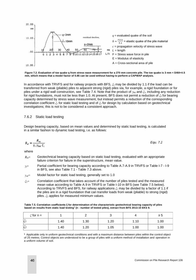
residual decline, q = evaluated quake of the soil
δ =𝐹(𝑡)𝐿
E 𝐴 = elastic quake of the pile material
c = propagation velocity of stress wave
L = length
F = Stress wave force in pile
E = Modulus of elasticity
A = Cross-sectional area of pile
Figure 7.2. Evaluation of toe quake q from stress wave measurement for a 270 mm concrete pile. The toe quake is 3 mm < D/60=4.5
mm, which means that a model factor of 0.85 can be used without having to perform a CAPWAP analysis.
In accordance with TRVFS and for railway projects with BFS, ξ5 may be divided by 1.1 if the load can be transferred from weak (pliable) piles to adjacent strong (rigid) piles via, for example, a rigid foundation or for piles under a rigid wall construction, see Table 7.4. Note that the product of γRd and ξ5, including any reduction for rigid foundations, must not be less than 1.0. At present, BFS does not permit a reduction of ξ5 for bearing capacity determined by stress wave measurement, but instead permits a reduction of the corresponding correlation coefficient ξ1 for static load testing and of ξ3 for design by calculation based on geotechnical investigations; this is not to be considered a consistent approach.
7.6.2 Static load testing
Design bearing capacity, based on mean values and determined by static load testing, is calculated in a similar fashion to dynamic load testing, i.e. as follows:
where
Equ. 7.2
Rm= Geotechnical bearing capacity based on static load testing, evaluated with an appropriate failure criterion for failure in the superstructure, mean value.
γt= Partial coefficient for bearing capacity according to Table A.7-A.9 in TRVFS or Table I-7 - I-9 in BFS, see also Table 7.1 - Table 7.3 above.
γRd= Model factor for static load testing, generally set to 1.0
ξ1= Correlation coefficient that takes account of the number of piles tested and the measured mean value according to Table A.9 in TRVFS or Table I-10 in BFS (see Table 7.5 below). According to TRVFS and BFS, for railway applications ξ1 may be divided by a factor of 1.1 if the piles are in a rigid foundation that can transfer loads from weak (pliable) to strong (rigid) piles. ξ2 applies for measured minimum values.
Table 7.5. Correlation coefficients ξ for determination of the characteristic geotechnical bearing capacity of piles
based on results from static load testing1 (n - number of tested piles), extract from BFS 2013:10 EKS 9.
ξ for n = 1 2 3 4 ≥ 5
ξ1 1.40 1.30 1.20 1.10 1.00
ξ2 1.40 1.20 1.05 1.00 1.00
1 Applicable only in uniform geotechnical conditions and with a maximum distance between piles within the control object of 25 metres. Control objects are understood to be a group of piles with a uniform method of installation and operation in a uniform volume of soil.
Commission on Pile Research Report 106
8 Preliminary assessment of bearing capacity
8.1 Toe resistance in rock and hard till
The Commission on Pile Research Information 2007:1 “Pile foundations - Basic information for planning engineers” contains rules of thumb for what toe resistance it is possible to detect with stress wave measurement of concrete piles with a cross section of 270 x 270 mm2 (corresponds to the old designations SP2, SP3) with 2500 kN for refusal in rock and 2000 kN for refusal in hard till. For a pile where the rock shoe dowel is driven to refusal in rock that is expected to take all the load, the toe resistance can be calculated using Coates & Gyenge’s formula (1973), see Commission on Pile Research report 98, Steel core piles.
Below are some general recommendations for the toe resistance σb (mean values) that it is possible to measure with stress wave measurement for end-bearing piles, where qu is the rock’s uniaxial compressive strength:
• Bored pile > 2d in intact rock or chiselled rock shoe dowel: σb = 5qu
• Rock shoe dowel (d < approx. 150 mm) on intact rock (semi-infinite medium): σb = 4qu
• Pile on intact rock (semi-infinite medium): σb = 3qu
• Pile driven to refusal on very hard coarse till: σb = 25 - 30 MPa
• Pile driven to refusal on very hard till with a high proportion of silt/fine sand: σb = 20 MPa
The bearing capacity can then be calculated as follows:
Equ. 8.1
where
Rm = Geotechnical bearing capacity that it is considered possible to measure using dynamic load testing
A = The cross-sectional area of the pile or dowel in contact with rock or hard till.
The uniaxial compressive strength (qu) of intact crystalline rock (granite, gneiss) is generally in the order of 150 - 250 MPa. For piles with a rock toe, it may be assumed that part of the pile’s transverse dimension is also in contact with rock/hard till after the chiselling of the rock shoe dowel. The geotechnical bearing capacity is therefore seldom designed. A low drop height is required in order to avoid damaging the dowel during chiselling. If the hard till cover is small to medium, it may be assumed that steel piles can be driven to refusal in rock, while concrete piles will be driven to refusal in the hard till. Dynamic probing is generally assumed to correspond to refusal for driven piles, but does not function satisfactorily in soil with stones or boulders. In contrast, a combination of earth/rock probing and dynamic probing usually provides a good basis for assessing the pile refusal level and also gives an indication of whether the soil contains boulders and stones, which is important. If the investigation is also extended with CPT1 with a special robust toe that can handle up to 100 MPa under toe compression and sampling with hard till samplers or sonic drilling, a good basis can be obtained for assessing end-bearing capacity, depth of driving in non-cohesive soil and whether there is a risk of false refusal. In an article by Axelsson, Dangré & Elvin (2004), based on a database, measured bearing capacities of standard concrete piles with cross sections 235 x 235 mm2 and 270 x 270 mm2 are reported as a function of the refusal penetration (penetration/10 blows) for various drop hammer weights and for various drop heights. This article can be used to get an idea of what bearing capacity may reasonably be achieved with different hammer weights, drop heights and pile dimensions.
Verification of geotechnical bearing capacity of piles according to Eurocode
8.2 Bearing capacity that can be demonstrated by stress wave measurement
The geotechnical bearing capacity in the limit state GEO can be determined by stress wave measurement. For stress wave measurement, the stress in the pile that occurs during driving should be limited in accordance with the instructions in the execution standards for displacement piles and micropiles, see Chapter 3. This leads to an upper limit value for the geotechnical bearing capacity that may reasonably be achieved without damaging the pile. Note that the recommendations given below do not refer to what values the piles can handle in the limit state GEO, i.e. the geotechnical bearing capacity of the pile may be a limiting factor.
In summary, in accordance with Eurocode, three main levels of bearing capacity may be distinguished, depending on the type of design and the scope of verification. Table 8.1 - Table 8.4 show the recommended minimum scope of measurement for each level for concrete and steel piles in projects designed in accordance with BFS or TRVFS. The tables can be used advantageously during project planning or as a control level during procurement procedures for piling work. The tables specify an
upper limit of the geotechnical bearing capacity as a function of the pile’s characteristic unit load Funit.
• For steel piles, Funit is defined as:the cross-sectional area multiplied by the liquid limit of the steel, i.e.
Funit= Asteel fyk.
• For concrete piles, Funit is defined as:the effective cross-sectional area multiplied by the
compressive strength of the concrete at the time of driving, i.e. Funit = Atot fcck where Atot Aconcrete
+ Asteel (Esteel / Econcrete − 1 ). Note that Funit can also be limited by the unit load for pile toe and
joints.
In order to minimise the risk of overloading the piles in connection with installation and driving to refusal, it is important that the designer specifies which strength class the concrete piles must have achieved at the time of installation. The strength must also be specified for steel piles so that the pile contractor can adjust the stress in the pile during driving.
When preparing the tender documentation, an assumption must be made as to the scope of testing that may be required; it is, however, only during the test piling that the appropriate scope is clarified. In some cases, it is not until the production piling that anomalies are discovered which necessitate extended testing.
It is recommended that a measurement level should be specified in the tender documentation in accordance with the tables below. Note that the scope of measurement shown in the tables is a minimum level. A larger scope of measurement is required for a higher load utilisation or if the piling conditions are deemed to make it necessary; see Chapter 9, Production control, for the recommended scope of measurement. The definitive scope of measurement is determined after the test piling or during production control, depending on the results obtained and observations during the piling work.
In the event of greater variations in pile lengths, bearing capacity or driving conditions, both extended test piling and extended production control may be required compared to what is stated in the tables below. Note that if more than three test piles are carried out within the control area (max. 25 x 25 m2), a higher load utilisation may be used than that specified in the tables. See below for how design bearing capacity is affected by the number of measured piles.
For level 2, it is assumed that at least 5% of the piles are measured, either as part of the test piling or in production control, if applicable. For driven piles, it is often difficult to determine from the geotechnical data whether any of the suggested problem situations described in Chapter 9 are present. A production control/test piling of at least 5% should therefore be a requirement. For bored steel piles driven to refusal in rock, the need for production control is generally not so great.
Commission on Pile Research Report 106
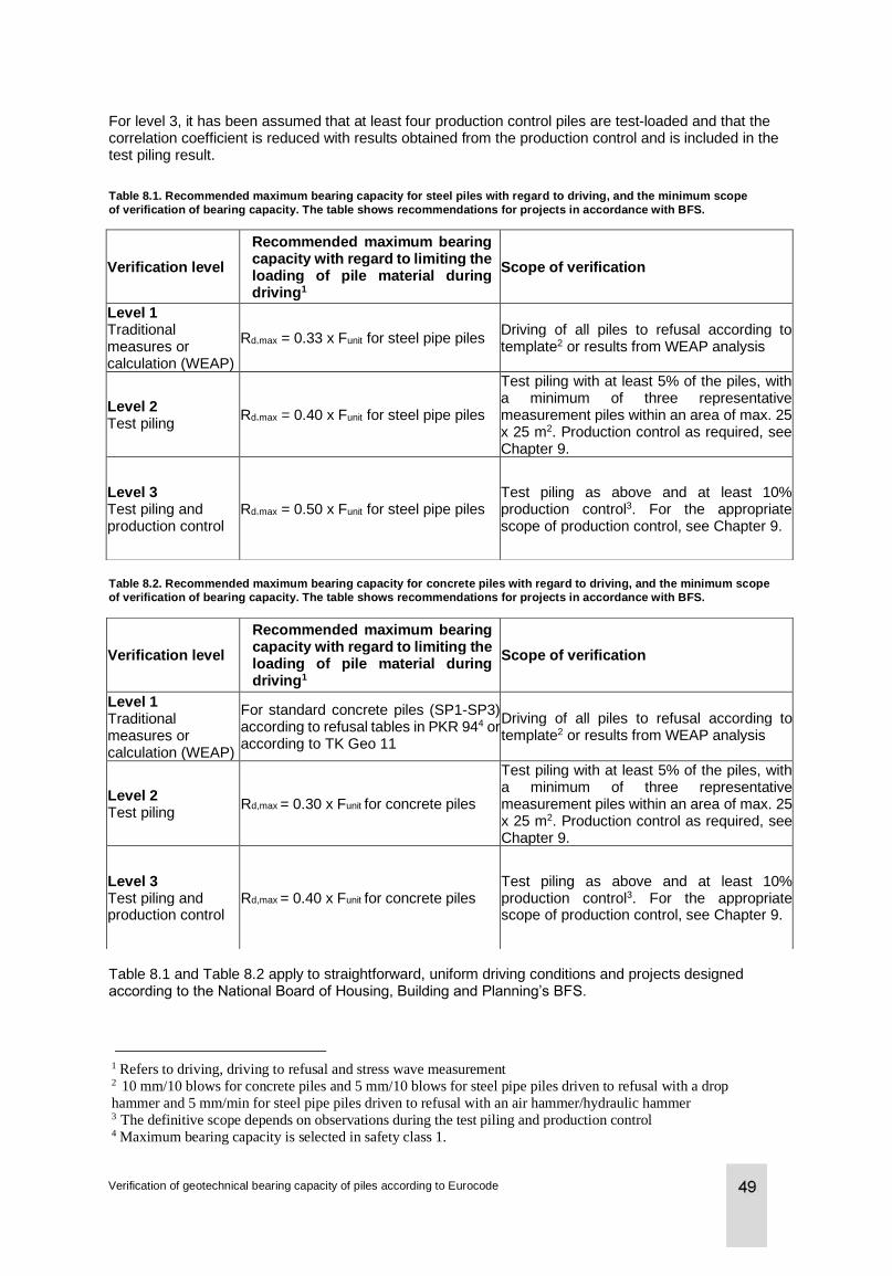
For level 3, it has been assumed that at least four production control piles are test-loaded and that the correlation coefficient is reduced with results obtained from the production control and is included in the test piling result.
Table 8.1. Recommended maximum bearing capacity for steel piles with regard to driving, and the minimum scope
of verification of bearing capacity. The table shows recommendations for projects in accordance with BFS.
Verification level
Recommended maximum bearing capacity with regard to limiting the loading of pile material during driving1
Scope of verification
Level 1 Traditional measures or calculation (WEAP)
Rd,max = 0.33 x Funit for steel pipe piles Driving of all piles to refusal according to template2 or results from WEAP analysis
Level 2 Test piling
Rd,max = 0.40 x Funit for steel pipe piles
Test piling with at least 5% of the piles, with a minimum of three representative measurement piles within an area of max. 25 x 25 m2. Production control as required, see Chapter 9.
Level 3 Test piling and production control
Rd,max = 0.50 x Funit for steel pipe piles Test piling as above and at least 10% production control3. For the appropriate scope of production control, see Chapter 9.
Table 8.2. Recommended maximum bearing capacity for concrete piles with regard to driving, and the minimum scope
of verification of bearing capacity. The table shows recommendations for projects in accordance with BFS.
Verification level
Recommended maximum bearing capacity with regard to limiting the loading of pile material during driving1
Scope of verification
Level 1 Traditional measures or calculation (WEAP)
For standard concrete piles (SP1-SP3) according to refusal tables in PKR 944 or according to TK Geo 11
Driving of all piles to refusal according to template2 or results from WEAP analysis
Level 2 Test piling
Rd,max = 0.30 x Funit for concrete piles
Test piling with at least 5% of the piles, with a minimum of three representative measurement piles within an area of max. 25 x 25 m2. Production control as required, see Chapter 9.
Level 3 Test piling and production control
Rd,max = 0.40 x Funit for concrete piles Test piling as above and at least 10% production control3. For the appropriate scope of production control, see Chapter 9.
Table 8.1 and Table 8.2 apply to straightforward, uniform driving conditions and projects designed according to the National Board of Housing, Building and Planning’s BFS.
Verification of geotechnical bearing capacity of piles according to Eurocode
1 Refers to driving, driving to refusal and stress wave measurement 2 10 mm/10 blows for concrete piles and 5 mm/10 blows for steel pipe piles driven to refusal with a drop
hammer and 5 mm/min for steel pipe piles driven to refusal with an air hammer/hydraulic hammer 3 The definitive scope depends on observations during the test piling and production control 4 Maximum bearing capacity is selected in safety class 1.
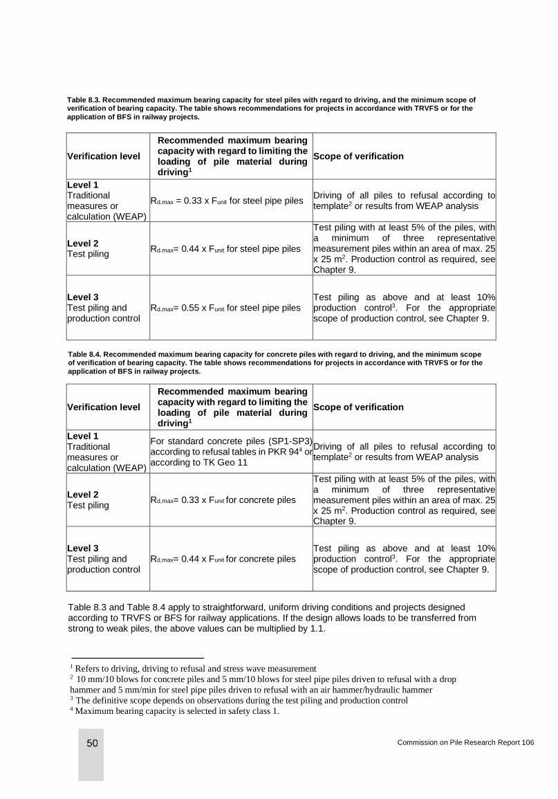
Table 8.3. Recommended maximum bearing capacity for steel piles with regard to driving, and the minimum scope of verification of bearing capacity. The table shows recommendations for projects in accordance with TRVFS or for the
application of BFS in railway projects.
Verification level
Recommended maximum bearing capacity with regard to limiting the loading of pile material during driving1
Scope of verification
Level 1 Traditional measures or calculation (WEAP)
Rd,max = 0.33 x Funit for steel pipe piles Driving of all piles to refusal according to template2 or results from WEAP analysis
Level 2 Test piling
Rd,max= 0.44 x Funit for steel pipe piles
Test piling with at least 5% of the piles, with a minimum of three representative measurement piles within an area of max. 25 x 25 m2. Production control as required, see Chapter 9.
Level 3 Test piling and production control
Rd,max= 0.55 x Funit for steel pipe piles Test piling as above and at least 10% production control3. For the appropriate scope of production control, see Chapter 9.
Table 8.4. Recommended maximum bearing capacity for concrete piles with regard to driving, and the minimum scope of verification of bearing capacity. The table shows recommendations for projects in accordance with TRVFS or for the
application of BFS in railway projects.
Verification level
Recommended maximum bearing capacity with regard to limiting the loading of pile material during driving1
Scope of verification
Level 1 Traditional measures or calculation (WEAP)
For standard concrete piles (SP1-SP3) according to refusal tables in PKR 944 or according to TK Geo 11
Driving of all piles to refusal according to template2 or results from WEAP analysis
Level 2 Test piling
Rd,max= 0.33 x Funit for concrete piles
Test piling with at least 5% of the piles, with a minimum of three representative measurement piles within an area of max. 25 x 25 m2. Production control as required, see Chapter 9.
Level 3 Test piling and production control
Rd,max= 0.44 x Funit for concrete piles Test piling as above and at least 10% production control3. For the appropriate scope of production control, see Chapter 9.
Table 8.3 and Table 8.4 apply to straightforward, uniform driving conditions and projects designed according to TRVFS or BFS for railway applications. If the design allows loads to be transferred from strong to weak piles, the above values can be multiplied by 1.1.
Commission on Pile Research Report 106
1 Refers to driving, driving to refusal and stress wave measurement 2 10 mm/10 blows for concrete piles and 5 mm/10 blows for steel pipe piles driven to refusal with a drop
hammer and 5 mm/min for steel pipe piles driven to refusal with an air hammer/hydraulic hammer 3 The definitive scope depends on observations during the test piling and production control 4 Maximum bearing capacity is selected in safety class 1.
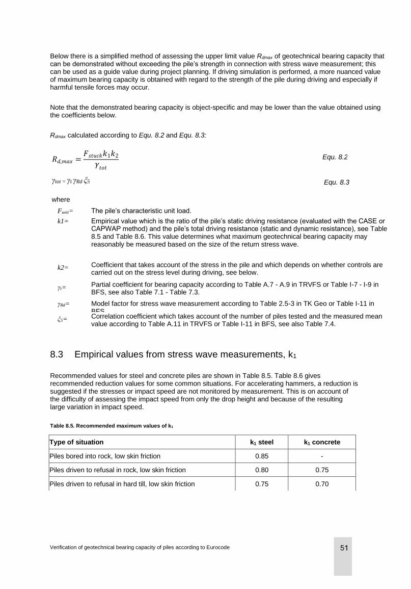
Below there is a simplified method of assessing the upper limit value Rdmax of geotechnical bearing capacity that can be demonstrated without exceeding the pile’s strength in connection with stress wave measurement; this can be used as a guide value during project planning. If driving simulation is performed, a more nuanced value of maximum bearing capacity is obtained with regard to the strength of the pile during driving and especially if harmful tensile forces may occur.
Note that the demonstrated bearing capacity is object-specific and may be lower than the value obtained using the coefficients below.
Rdmax calculated according to Equ. 8.2 and Equ. 8.3:
Equ. 8.2
Equ. 8.3
where
Funit= The pile’s characteristic unit load.
k1= Empirical value which is the ratio of the pile’s static driving resistance (evaluated with the CASE or CAPWAP method) and the pile’s total driving resistance (static and dynamic resistance), see Table 8.5 and Table 8.6. This value determines what maximum geotechnical bearing capacity may reasonably be measured based on the size of the return stress wave.
k2= Coefficient that takes account of the stress in the pile and which depends on whether controls are carried out on the stress level during driving, see below.
γt= Partial coefficient for bearing capacity according to Table A.7 - A.9 in TRVFS or Table I-7 - I-9 in BFS, see also Table 7.1 - Table 7.3.
γRd= Model factor for stress wave measurement according to Table 2.5-3 in TK Geo or Table I-11 in BFS.
ξ5= Correlation coefficient which takes account of the number of piles tested and the measured mean value according to Table A.11 in TRVFS or Table I-11 in BFS, see also Table 7.4.
8.3 Empirical values from stress wave measurements, k1
Recommended values for steel and concrete piles are shown in Table 8.5. Table 8.6 gives recommended reduction values for some common situations. For accelerating hammers, a reduction is suggested if the stresses or impact speed are not monitored by measurement. This is on account of the difficulty of assessing the impact speed from only the drop height and because of the resulting large variation in impact speed.
Table 8.5. Recommended maximum values of k1
Type of situation k1 steel k1 concrete
Piles bored into rock, low skin friction 0.85 -
Piles driven to refusal in rock, low skin friction 0.80 0.75
Piles driven to refusal in hard till, low skin friction 0.75 0.70
Verification of geotechnical bearing capacity of piles according to Eurocode
𝑅𝑑,𝑚𝑎𝑥 =𝐹𝑠𝑡𝑢𝑐𝑘𝑘1𝑘2
𝛾𝑡𝑜𝑡
γtot = γt γRd ξ5
Table 8.6. Suggested reduction values for k1.
Type of situation Reduction of k1
End-bearing piles, pile length > 20 m, moderate to high skin resistance 0.1 - 0.2
Piles driven to refusal in a thick layer of hard till or in hard till with a high proportion of silt/fine sand
0.1 - 0.2
8.4 Stress monitoring, k2
Values of k2 are shown in Table 8.7. If stress wave measurement is performed on steel piles and the steel stress is monitored during installation, driving to refusal and load testing, k2 in Equ. 8.2 can be set to 1.1 (i.e. 1.1 times the liquid limit of the steel) according to execution standard SS-EN 12699:2000, displacement piles. If, conversely, the stress in the pile is not monitored during production, this coefficient is set to 0.9. The corresponding values for driven concrete piles are 0.9 (i.e. 0.9 times the compressive strength of the concrete) with stress monitoring and 0.8 if no monitoring is performed. The higher values can also be used if low-impact driving and driving to refusal are performed clearly below the compressive yield limit of the pile material. If the stresses in the piles are monitored during installation and driving to refusal, higher stresses are permitted in the pile. This monitoring of stresses should be performed during a continuous production control. To monitor the stresses in the pile, measurement of the impact speed of the hammer may be an alternative to stress wave measurement.
For piles that are driven to refusal with accelerating hammers without continuous measurement of supplied energy (e.g. by registering the hammer’s impact speed), the values in Table 8.7 should be reduced by 0.10, unless the hammer’s impact speed is measured continuously during production.
Table 8.7. Values of k2 according to execution standards.
Type of situation k2 steel k2 concrete
No risk of the stress level in the pile being exceeded during installation and driving to refusal. If necessary, control is performed by stress wave measurement or by measuring the impact speed of the hammer.
1.1 0.9
There is a risk that the stress level in the pile may be exceeded and no control is performed during production.
0.9 0.8
8.5 Effect of pile length and hammer weight
The drop height of the hammer (impact speed) that is required to verify the bearing capacity must be selected based on the results of the test piling. For short piles in relation to the size of the hammer (impedance), a lower drop height should be selected for verifying the same bearing capacity as for medium to long piles. If the drop height is not reduced for short piles, there is a substantial risk that these piles will be overloaded during driving to refusal or test piling. In short piles, it is possible to calculate piles shorter (in metres) than the equivalent of double the hammer weight in tonnes, see example in Figure 8.1.Chapter 5 also presents examples of suitable drop heights for various pile lengths with refusal rules according to traditional measures. Driving simulation is otherwise an excellent tool for assessing the reduction of drop height in short piles. When driving steel piles to refusal with a hydraulic or compressed air hammer, the weight of the ram should be at least 2 times the weight of the pile per metre.
Commission on Pile Research Report 106
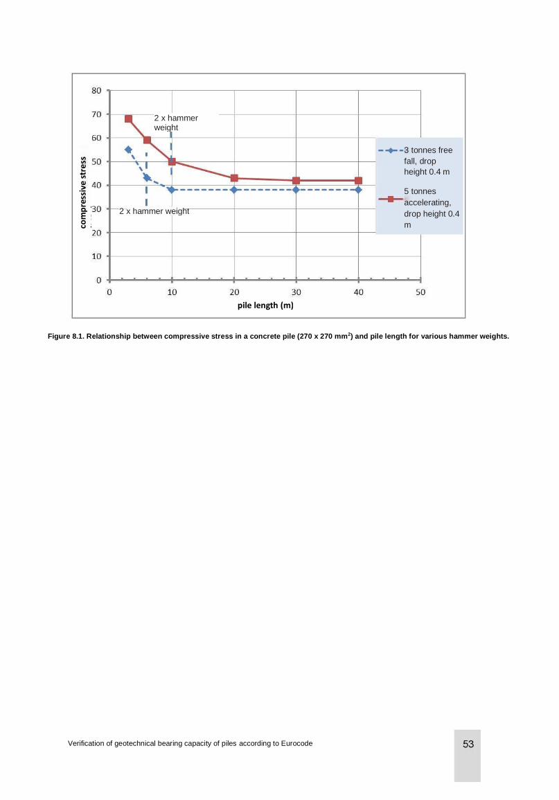
Figure 8.1. Relationship between compressive stress in a concrete pile (270 x 270 mm2) and pile length for various hammer weights.
pile length (m)
2 x hammer weight
2 x hammer weight
com
pre
ssiv
e s
tre
ss
(MP
a)
3 tonnes free
fall, drop
height 0.4 m
5 tonnes
accelerating,
drop height 0.4
m
Verification of geotechnical bearing capacity of piles according to Eurocode
9 Production control with determination of bearing capacity
9.1 General
Production control with determination of bearing capacity is generally performed by means of stress wave measurement (dynamic load tests) or static tensile load tests. Static testing under compression is not commonly used as a form of production control in Sweden today.
SS-EN 1997-1, section 7.9, specifies that all piles must be monitored during production and that pile records must be kept. Production control with, for example, determination of the bearing capacity and integrity of the pile should be performed if observations during installation indicate significant deviations from expected behaviour with regard to the geotechnical conditions or previous experiences on site. A replacement pile may need to be installed if there are uncertainties about the quality of the pile. The selection of the appropriate number of piles to be controlled should be made on the basis of what is observed during installation. Production control is intended to complement test piling (design by testing).
According to Eurocode 7, section 7.5.2.3, it is possible to perform production control with a test load that is at least as large as the design load. This applies primarily to static load testing, e.g. for skin friction piles, injected piles or cohesion piles where one does not wish to risk mobilising the bearing capacity before the piles are fully fixed. For static load testing as a form of production control, however, it is recommended that at least 1.1 times the design load should be used. Note that these piles are not included in the design data, but have the purpose of verifying the function of the piles. On the other hand, this possibility has no major practical use in dynamic load testing, as it is rarely associated with a greater cost than load testing up to the same load levels as for test piling. If the test load corresponds to that used in the test piling, it is possible to successively revise the design bearing capacity during production. As new data is received, the correlation coefficient ξ can be reduced in view of the increased number of tests.
9.2 Suggestions for production control
Below there are suggestions for situations in which production control with load testing is recommended. The list is not exhaustive and there may be many more reasons for performing production control. It is appropriate, after the test piling has been performed, to decide on the scope and type of production control that is to be carried out. Observations during production may, however, subsequently lead to a change in this decision.
1) Small changes in pile dimensions. Repeated test piling is not always necessary in the event of minor changes in the pile’s cross-sectional area or diameter. Conversely, one should check the refusal criterion and verify that there is a good correlation for bearing capacity between the pile dimensions. For steel piles in rock with a small permanent penetration and where the bearing capacity is not mobilised during load testing, a larger difference in ratio between the greatest and smallest cross-sectional area can be accepted; double the difference is a reasonable maximum figure. In the event of major changes, new test piling is recommended.
2) In the case of false pile refusals, i.e. when the refusal penetration increases during re-driving a certain time after driving to refusal. The re-driving should be performed at least 12 hours after the driving to refusal. Control of false pile refusals can also be carried out by checking the penetration under the same conditions as during driving to refusal. Quake measurement may also give an indication of false refusals.
3) Local sloping rock with low overlying thickness of stabilising non-cohesive soil.
Commission on Pile Research Report 106
4) Soil with boulders, where there is a risk of driving failure or where the driving to refusal is uncertain. Boulders in hard till are generally not a major problem, as the surrounding soil is stabilising.
5) Strongly varying geotechnical conditions or poor geological overview of the area and where there is a risk that the test piles do not give a full picture of the situation. An indication of this may be that the test piles show a large variation in bearing capacity or there is a significant difference in how the piles behave during installation, e.g. a large difference in the number of blows.
6) Ground heave and loss of end-bearing capacity during driving of adjacent piles. This can also be checked by measuring the piles.
7) Pile group effects, i.e. effect on adjacent piles when driving piles in groups. This is primarily the result of compaction effects or a change in the effective stress in the soil; this may be either short-term (elevated pore pressure) or long-term.
8) With the utilisation of a high geotechnical bearing capacity, where there is insufficient local experience. Examples of high utilisation of the soil strength would be more than 20 MPa or 25 MPa toe resistance in silty or coarse hard till respectively or more than 100 kPa skin resistance in a non-cohesive soil.
9) If installation equipment is replaced. It should be checked that the new hammer has an equivalent efficiency and provides the corresponding refusal criterion.
10) Piles fabricated in-situ. This type of pile, e.g. bored piles, may display a greater variation in structural and geotechnical quality than prefabricated piles.
11) Control of stresses during driving and driving to refusal. A greater utilisation of the pile’s bearing capacity can be applied if the stresses are checked. See factor k2 in Chapter 8.
12) High degree of utilisation with regard to the piles’ design bearing capacity or an uncertainty in the functioning of the pile after installation, e.g. on account of play in joints, damage to concrete piles, curvature of steel piles etc.
Table 9.1. Suggested scope of production control by stress wave measurement.
Control situation
Proportion, % Minimum distance
Number of piles Specified piles
1
≥ 3 piles
2 10 - 25 10 - 20 m
3 10 - 25
4 10 - 25
5
<5 - 15 m
6 5 - 10
At least one per pile group
e.g. the first driven pile in the group 7 5 - 10
8 5 - 10
Highly loaded piles
9
≥ 3 piles
10 10 - 25
11 5 - 10
12 10 - 20 Piles in Level 3
The higher proportions suggested in Table 9.1 should be used for small projects with a relatively low number of piles in total. In order to obtain sufficient information about the piling conditions, production control should include no fewer than four piles, irrespective of how small the project is.
The quantity of production piles can be selected on the basis of one or more of the following alternatives:
• The percentage of driven piles
• The minimum distance between tested piles. This is appropriate if the purpose is to verify the geotechnical conditions in the area
• A certain number of piles, e.g. one pile in each pile group
Verification of geotechnical bearing capacity of piles according to Eurocode
• Certain specific piles, e.g. the most heavily loaded piles or the first driven pile in a pile group
If several situations are applicable in a project, the proportion that gives the highest number of measured piles is selected; the above percentages do not therefore need to be added together.
9.3 Complementary control methods
In many situations, load testing can be supplemented with other control methods. Examples of some of these methods include:
• Blow count, recording the number of blows per 20 cm penetration of the pile
• Continuous registration of the hammer’s impact speed (driving energy)
• Integrity control (low strain testing). Detection and determination of location of possible damage to non-jointed concrete piles
• Driving to refusal during control driving or re-driving
• Quake measurement to detect the bearing capacity of weak piles, significantly curved piles or elevated pore pressure
• Straightness measurement of steel pipe piles with inclinometer. Insertion of an upside-down torch can be used to select suitable piles where significant curvature is feared. The use of a gauge is also an alternative, but there is a risk that the gauge will become stuck if the curvature is too great
One or more of these control methods can be used together with stress wave measurement to obtain a high but cost-effective level of control and to optimise the piling work.
The following controls are primarily used to check movement or stability in the surrounding area:
• Precision measurement of piles and points on the ground surface to check settling, heave or horizontal displacement
• Automatic registration of various installation parameters for bored piles
• Pore pressure sensor in the ground. Control of elevated pore pressure that may indicate insufficient bearing capacity of piles or stability problems in the surrounding area
• Inclinometer measurement, measurement of mass displacement that may indicate ground heave and stability problems in the surrounding area
Commission on Pile Research Report 106

10 Guidelines for the performance of testing
As can be seen from Chapter 7, for uncomplicated projects with end-bearing piles and known piling conditions, a practice has been developed which means that test piling and any production control are carried out continuously during the production phase. The introduction of control areas, with a number of piles being tested in each control area, has accelerated this development.
Test piling is often somewhat simplified for this type of project, but should in principle be performed as described below.
10.1 Preparatory work
Prior to test piling, driving to refusal and stress wave measurement, the geotechnical conditions and driving conditions should be evaluated as follows:
• Soil types and soil variations in the working area.
• Expected increase in bearing capacity between driving and re-driving.
• Time when the pile is to be test-loaded.
• The pile’s design bearing capacity for checking that the piles are not overloaded during driving, driving to refusal or re-driving.
• For skin-bearing piles: calculation of preliminary length in soil according to a geostatic calculation method.
• For end-bearing piles: preliminary refusal rule that meets the specified requirements for geotechnical bearing capacity. The refusal rule should be calculated in accordance with Commission on Pile Research report 92 Computer simulation of pile driving or alternatively according to the refusal tables in the Swedish Transport Administration document TRVFS. Preliminary refusal rules should be compared with measurement results during test piling.
• The required hammer weight and drop height should be assessed. For driving steel piles to refusal, it is recommended that the hammer weight for light hammers should be at least 2 times the weight of the pile per metre. This also applies to bored steel pipe piles. With dynamic testing of steel piles, a hammer weight of 2.5% of the pile load and a drop height of 6 - 7% of the pile length are generally sufficient for verifying the bearing capacity. For short piles driven into rock, the hammer weight and drop height may be slightly lower. The computer program WEAP can be used to assess the required drop height more accurately.
• It should be noted that the verification of the bearing capacity of steel piles with loads in Level 3 in accordance with Chapter 8 entails particularly stringent requirements in terms of the hammer striking the pile with well-centred blows, in order not to risk overloading the steel. This means, for example, that great care is required in cutting and that it must be possible to adjust the hammer’s inclination and abutment against the pile. It must, of course, be possible to control the hammer with the aid of a guide. If stress wave measurement is performed with the sensors placed on a so-called measuring jack, this is even more important, as losses occur during the transmission of force between the hammer and the pile. This arrangement also complicates the centring of the blows on the pile. If the piles are very highly loaded, it may be difficult to verify the required bearing capacity if measuring jacks are used.
• For steel pipe piles with a high load utilisation for the limit state GEO, an alternative may be to increase the stiffness of the pile by filling the piles with concrete and performing stress wave measurements after the concrete has hardened. It is important that the piles should be filled with concrete all the way to the top, see Commission on Pile Research report 104 Bored steel pipe piles. According to report 104, the required bearing capacity can often be verified without concrete filling for smaller pile cross-sections, while concrete filling is required for thicker bored steel pipe piles, e.g. 406 x 12.5. With the stress wave measurement of concrete-filled steel pipe piles, there is a risk that the interaction between the steel and the concrete might decrease in the upper part of the pile, which should be taken into account if the concrete has a load-bearing function for limit state STR.
Verification of geotechnical bearing capacity of piles according to Eurocode
• The test piles should be marked every metre (unless the number of blows per metre of penetration is registered automatically by the pile rig).
10.2 Test piling
The blows on the test piles should be counted throughout driving. The number of blows per pile penetration (blows/m or blows/0.2 m) and drop height should be documented.
Stress wave measurement is performed from a level where the soil strength is of interest for establishing refusal rules. If stresses in the pile during driving are of interest, stress wave measurement should be performed at relevant levels or as a continuous measurement throughout the driving process. During “driving to refusal”, the bearing capacity is measured for various penetration values.
Test piling and stress wave measurement should include at least three piles/control area in accordance with the National Board of Housing, Building and Planning’s BFS 2013:10, tables I-7 to I-11 and the Swedish Transport Administration’s TRVFS 2011:12, tables A.6 - A.9 and A.11. These tables are also presented in section 7.6.
The geotechnical bearing capacity should be assessed on the basis of the results of calculated and verified requirements for driving to refusal. A pile driven in substantial layers of solid soil generally displays a significant increase in bearing capacity over time. Most of this increase is due to the fact that the skin resistance increases after being disturbed during the driving of the pile, see Commission on Pile Research report 103 for further information.
10.3 Re-driving
Stress wave measurement should be performed during re-driving of the piles, firstly to check that there are no false refusals, and secondly to assess the increase in geotechnical bearing capacity. The piles should be re-driven no earlier than 12 hours after driving. For piles that are driven in silty soils, a longer time may be required between installation and testing, see BFS 2013:10 EKS 9, Chapter 7.1, section 2. If the increase in bearing capacity is to be taken into account, it is necessary that the time of re-driving should be adapted to the soil type. Piles driven in coarse-grained soils (gravel/sand) are to be re-driven 1 - 10 days after driving. Piles driven in fine-grained soils (silt/clay) are to be re-driven 1 - 4 weeks after driving. In order to obtain a more reliable forecast of the increase in geotechnical bearing capacity, measurements should be performed on more than two occasions. For more information, see Commission on Pile Research report 91.
10.4 Evaluation of bearing capacity
The bearing capacity should be determined by an evaluation of stress wave processes, in which both force and particle velocity are recorded. The geotechnical conditions must be taken into account in the evaluation. The evaluation must be carried out by experienced personnel who are well trained in stress wave theory and stress wave measurements and who have a good geotechnical knowledge. For the interpretation of the measurement results, please refer to the Piling Foundations Handbook, section 9.3.
For predominantly end-bearing piles, the bearing capacity can be evaluated using only the CASE method with appropriately selected soil damping (JC factor). Alternatively, signal matching of the stress wave can be performed using the computer program CAPWAP or equivalent. Computer analysis with signal matching should be used to check measurement results and the JC factor in the CASE method if:
• the piles display a significant level of skin resistance
• large penetrations occur, with penetration s > D/50 mm per blow for driving with drop hammers or s > 20 mm/minute for driving with compressed air hammers
• the piles have varying cross-sections and impedance
Commission on Pile Research Report 106
• the function of the piles in soil or the measurement result deviate from the expected conditions
The recommended quantity of CAPWAP analyses is generally 20 - 40% of the measured piles, but at least 2 piles. If the correlation is acceptable, the other piles evaluated with CASE can be taken into account as if they had also been signal-matched, and thus a lower overall safety factor can be used (lower model factor). In corresponding fashion, a correlation between static and dynamic load testing can be used and may give a lower correlation factor.
CAPWAP analysis is generally not necessary for end-bearing piles that are driven through loose clay down to hard till. For piles through loose soil layers with refusal against rock, both the JC factor and the CAPWAP analysis are of no interest. For skin friction piles in clay and silty soil, or in cases in which there are significant variations in bearing capacity, pile length, piling conditions etc., CAPWAP analyses of more than 20 - 40% may be justified.
10.5 Evaluation of refusal criteria/driving depth
For predominantly end-bearing piles, object-specific refusal criteria should be established, taking account of:
• driving to refusal during driving
• increase in bearing capacity
• any downdrag due to negative skin friction
• ensuring that the pile is not damaged by driving
• variations with regard to geotechnical conditions, pile lengths and hammer efficiency.
Penetration values for driving to refusal should generally be selected within the interval: s = 5 - 30 mm/10 blows for driving with a drop hammer s = 5 - 30 mm/minute for driving with a compressed air or impact hammer.
For skin friction piles, the refusal rule can be combined with or replaced by a driving depth. To determine what pile length in soil meets the requirements for geotechnical bearing capacity, the skin resistance per unit length (often 1 or 2 m) and total skin resistance per depth of pile toe are reported. The distribution of skin bearing capacity is compared with a geotechnical investigation to check that the computer-analysed version represents the soil conditions. Computer analysis is carried out on representative piles to ensure that any variation in the soil has been taken into account.
The selection of pile lengths for the project will be based on a consideration of the results of:
• geotechnical assessment
• properties during driving
• properties during re-driving
10.6 Production control of piles
For verification that piles which have been installed in accordance with the instructions derived from test piling meet the specified requirements, stress wave measurements can be performed in the form of production control. Production control includes the following:
a) ensuring that the piles’ function in soil corresponds to the test piles
b) ensuring that the bearing capacity meets the specified requirements
c) ensuring that the piles are not damaged (integrity control)
Verification of geotechnical bearing capacity of piles according to Eurocode
If the piles do not meet the specified requirements, a supplementary investigation of the piling is carried out. Production control should be performed by personnel who have been specially trained in stress wave measurement technology and who work continuously with stress wave measurements.
10.7 Evaluation of production control
The bearing capacity of a pile is generally evaluated using the CASE method with the JC value according to the test piling. The integrity control of piles, based on stress wave measurement with force and velocity curves, must show that the piles are functioning correctly.
10.8 Integrity control
The integrity of a pile refers to its serviceability. Integrity control by stress wave measurement is performed with a hammer blow on the pile and involves checking for damage to pile material or joints. Integrity control can be performed either with a heavy hammer (high strain) for both steel and concrete piles or with a light hammer (low strain) for concrete piles. Integrity control with a heavy hammer is performed in connection with a normal stress wave measurement for the determination of bearing capacity.
In integrity control with a light hammer, the stress wave is generated in the pile via a blow, for example with a sledgehammer. The method is both quick and simple, and indicates the presence and location of cracks and other damage. This method, however, generally produces a considerably inferior determination of the degree of damage than when using a heavy hammer. Integrity control with a light hammer is, moreover, only accepted for non-jointed piles, as the stress wave is normally not able to pass beyond a joint. In general, this method can be used for a pile length of approximately 30 times the pile’s cross-sectional dimension (edge dimension or diameter).
With integrity control, piles can be classified according to the degree of damage (β factor) in accordance with Commission on Pile Research report 89. A benchmark may be that the β factor should be greater than 0.8 in order for the piles to be accepted for full load, but since concrete piles with untensioned reinforcement contain both joints and cracks, this should be assessed on a case-by-case basis for this type of pile. If a gradual reduction in stiffness is found for a concrete pile that is tested shortly after driving, follow-up measurements may be of interest, as concrete cracks can “heal” over time.
10.9 Test piling with static load testing
Static load testing is sometimes performed in Sweden. Section 7.3 of this report, section 9.2 of the Piling Foundations Handbook and Commission on Pile Research report 59 provide information on the performance of testing and the interpretation of results. Static load testing can be performed for both compression and tension. In the case of compressive loading, which is relatively rare today in Sweden, abutment piles are often used; these are wrapped around the pile that is to be tested. During the load testing, a beam system is placed between the abutment piles, which are then tension-loaded while the test pile is compression-loaded by means of a loading jack. Another alternative is to arrange counterweights on a beam system on top of the pile and compression-load it with a jack. For bored piles, it is possible to evaluate the pile’s bearing capacity (both end-bearing and skin friction) by installing one or more so-called Osterberg cells at a suitable level in the pile. Any reinforcement cage is provided with an overlapping joint with the same cross section. The pile can then continue to be used as a production pile. Tensile testing is performed to demonstrate the size of the skin friction bearing capacity of, for example, cast steel core piles and for bored injected piles, e.g. Titan piles or MAI struts. It is also permitted to demonstrate compressive loads in the same manner. For injected piles, one should pay close attention to the issue of buckling, as these piles can be very slender. If the piles are exposed only to a tensile force, it is possible, in spite of a demonstrated geotechnical bearing capacity, to miss the fact that the piles would have cracked in the compressive load case to which the piles will actually be exposed in practice. One should also be aware that the test procedure itself is generally the design load case.
Commission on Pile Research Report 106

It is easy to start from the tensile loading of the pile and dimension the tensile bearing capacity accordingly, but during testing a safety factor of 1.0 is seldom sufficient. In many cases, one does not wish to load the strut/pile all the way up to the yield point, but to have a small margin, which further contributes to the problem.
Verification of geotechnical bearing capacity of piles according to Eurocode
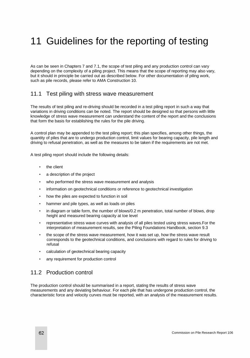
11 Guidelines for the reporting of testing
As can be seen in Chapters 7 and 7.1, the scope of test piling and any production control can vary depending on the complexity of a piling project. This means that the scope of reporting may also vary, but it should in principle be carried out as described below. For other documentation of piling work, such as pile records, please refer to AMA Construction 10.
11.1 Test piling with stress wave measurement
The results of test piling and re-driving should be recorded in a test piling report in such a way that variations in driving conditions can be noted. The report should be designed so that persons with little knowledge of stress wave measurement can understand the content of the report and the conclusions that form the basis for establishing the rules for the pile driving.
A control plan may be appended to the test piling report; this plan specifies, among other things, the quantity of piles that are to undergo production control, limit values for bearing capacity, pile length and driving to refusal penetration, as well as the measures to be taken if the requirements are not met.
A test piling report should include the following details:
• the client
• a description of the project
• who performed the stress wave measurement and analysis
• information on geotechnical conditions or reference to geotechnical investigation
• how the piles are expected to function in soil
• hammer and pile types, as well as loads on piles
• in diagram or table form, the number of blows/0.2 m penetration, total number of blows, drop height and measured bearing capacity at toe level
• representative stress wave curves with analysis of all piles tested using stress waves.For the interpretation of measurement results, see the Piling Foundations Handbook, section 9.3
• the scope of the stress wave measurement, how it was set up, how the stress wave result corresponds to the geotechnical conditions, and conclusions with regard to rules for driving to refusal
• calculation of geotechnical bearing capacity
• any requirement for production control
11.2 Production control
The production control should be summarised in a report, stating the results of stress wave measurements and any deviating behaviour. For each pile that has undergone production control, the characteristic force and velocity curves must be reported, with an analysis of the measurement results.
Commission on Pile Research Report 106
11.3 Integrity control
Integrity measurements of the “high strain” type should be included, together with other measurement results, in both the test piling report and the production control report. Observations regarding damage and cracks must be commented on. Integrity measurements of the “low strain” type with an accelerometer and sledgehammer should be included in a separate report showing the velocity curve for each tested pile.
11.4 Test piling with static load testing
Static load testing can be reported in accordance with section 9.2 of the Piling Foundations Handbook. See also Commission on Pile Research report 59 and section 7.3 of this report.
Verification of geotechnical bearing capacity of piles according to Eurocode
12 References
Olsson C. and Holm G. (1993), “Piling Foundations Handbook”, AB Svensk Byggtjänst.
Likins G. et al. (1996), “CAPWAP correlation studies”, Proc. 5th int. conf. on the appl. of stress-wave theory to piles, Orlando, Florida.
Axelsson G., Lindgren J., Giding J. (2012), “Dynamisk provning av Mantelburna stålkärnepålar” (Dynamic testing of skin friction steel core piles), Samhällsbyggaren no. 1/12.
Coates and Gyenge (1973), “Incremental design in rock mechanics”, Mines Branch monograph; no. 880.
Axelsson G, Dangré M., Elvin E. (2004), ”Toe resistance of piles driven into dense moraine”, Proc. 7th int. conf. on the appl. of stress-wave theory to piles, Kuala Lumpur, Malaysia.
The Norwegian Piling Committee, Norwegian Geotechnical Society, Schram Simonsen A. et al (2012), “Pile Guide 2012”.
Hermansson, I. (2011). “Visa bärförmågan - ett fall för en riktig hejare” (Demonstrating bearing capacity - a case for a proper hammer) Påldag 11, Gothenburg 2011-05-12.
Grävare CJ, Hermansson I, Mure JN, Kightley ML. CAPWAP - an alternative to traditional load testing of piles. Väg- och vattenbyggaren 7-8 1983.
Type approval 3198/89 Rules for concrete piles. Boverket (National Board of Housing, Building and Planning) 1990-01-08.
Type approval 0656/94, RR piles, Ruukki Sverige AB
Commission on Pile Research Report 106
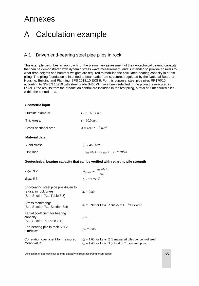
Annexes
A Calculation example
A.1 Driven end-bearing steel pipe piles in rock
This example describes an approach for the preliminary assessment of the geotechnical bearing capacity that can be demonstrated with dynamic stress wave measurement, and is intended to provide answers to what drop heights and hammer weights are required to mobilise the calculated bearing capacity in a test piling. The piling foundation is intended to bear loads from structures regulated by the National Board of Housing, Building and Planning, BFS 2013:10 EKS 9. For this purpose, steel pipe piles RR170/10 according to SS-EN 10219 with steel grade S460MH have been selected. If the project is executed in Level 3, the results from the production control are included in the test piling, a total of 7 measured piles within the control area.
Geotechnical bearing capacity that can be verified with regard to pile strength
Equ. 8.2: 𝑅𝑑,𝑚𝑎𝑥 =𝐹𝑠𝑡𝑢𝑘 𝑘1 𝑘2
𝛾𝑡𝑜𝑡
Equ. 8.3: γtot = γt γRd ζ5
Geometric input
End-bearing steel pipe pile driven to
refusal in rock gives:
(See Section 7.1, Table 8.5)
k1 = 0.80
Stress monitoring: (See Section 7.1, Section 8.4)
k2 = 0.90 for Level 2 and k2 = 1.1 for Level 3
Partial coefficient for bearing capacity: (See Section 7, Table 7.1)
γt = 13
End-bearing pile in rock S < 2 mm/blow:
γRd = 0.85
Correlation coefficient for measured mean value:
ξ5 = 1.60 for Level 2 (3 measured piles per control area)
ξ5 = 1.48 for Level 3 (a total of 7 measured piles)
Verification of geotechnical bearing capacity of piles according to Eurocode
Outside diameter: Dy = 168.3 mm
Thickness: t = 10.0 mm
Cross-sectional area: A = 4.97 * 103 mm2
Material data
Yield stress: fy = 460 MPa
Unit load: Funit =fy A → Funit = 2.29 * 103kN
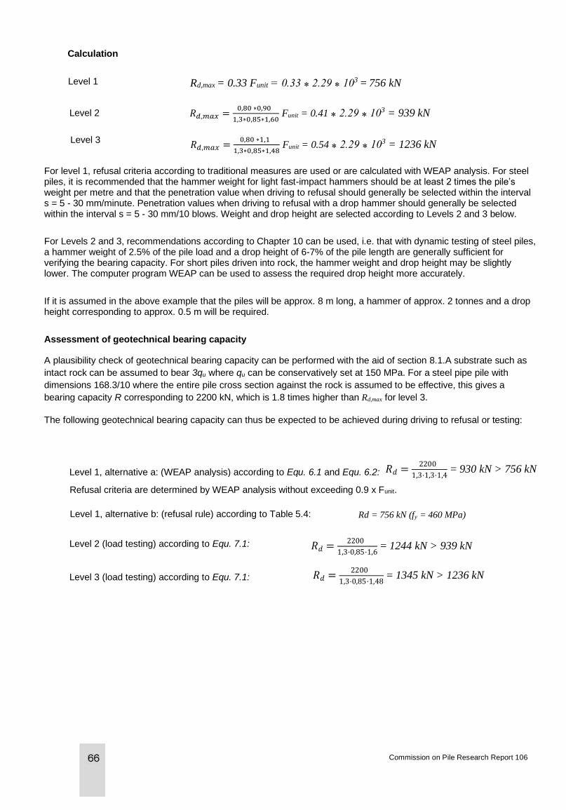
Calculation
Level 1
Level 2
Level 3
For level 1, refusal criteria according to traditional measures are used or are calculated with WEAP analysis. For steel piles, it is recommended that the hammer weight for light fast-impact hammers should be at least 2 times the pile’s weight per metre and that the penetration value when driving to refusal should generally be selected within the interval s = 5 - 30 mm/minute. Penetration values when driving to refusal with a drop hammer should generally be selected within the interval s = 5 - 30 mm/10 blows. Weight and drop height are selected according to Levels 2 and 3 below.
For Levels 2 and 3, recommendations according to Chapter 10 can be used, i.e. that with dynamic testing of steel piles, a hammer weight of 2.5% of the pile load and a drop height of 6-7% of the pile length are generally sufficient for verifying the bearing capacity. For short piles driven into rock, the hammer weight and drop height may be slightly lower. The computer program WEAP can be used to assess the required drop height more accurately.
If it is assumed in the above example that the piles will be approx. 8 m long, a hammer of approx. 2 tonnes and a drop height corresponding to approx. 0.5 m will be required.
Assessment of geotechnical bearing capacity
A plausibility check of geotechnical bearing capacity can be performed with the aid of section 8.1.A substrate such as
intact rock can be assumed to bear 3qu where qu can be conservatively set at 150 MPa. For a steel pipe pile with
dimensions 168.3/10 where the entire pile cross section against the rock is assumed to be effective, this gives a
bearing capacity R corresponding to 2200 kN, which is 1.8 times higher than Rd,max for level 3.
The following geotechnical bearing capacity can thus be expected to be achieved during driving to refusal or testing:
Level 1, alternative a: (WEAP analysis) according to Equ. 6.1 and Equ. 6.2:
Refusal criteria are determined by WEAP analysis without exceeding 0.9 x Funit.
Level 1, alternative b: (refusal rule) according to Table 5.4: Rd = 756 kN (fy = 460 MPa)
Level 2 (load testing) according to Equ. 7.1:
Level 3 (load testing) according to Equ. 7.1:
Commission on Pile Research Report 106
Rd,max = 0.33 Funit = 0.33 ⁎ 2.29 ⁎ 103 = 756 kN
𝑅𝑑,𝑚𝑎𝑥 =0,80 ∗0,90
1,3∗0,85∗1,60 Funit = 0.41 ⁎ 2.29 ⁎ 103 = 939 kN
𝑅𝑑,𝑚𝑎𝑥 =0,80 ∗1,1
1,3∗0,85∗1,48 Funit = 0.54 ⁎ 2.29 ⁎ 103 = 1236 kN
𝑅𝑑 =2200
1,3·1,3·1,4 = 930 kN > 756 kN
𝑅𝑑 =2200
1,3·0,85·1,6 = 1244 kN > 939 kN
𝑅𝑑 =2200
1,3·0,85·1,48 = 1345 kN > 1236 kN
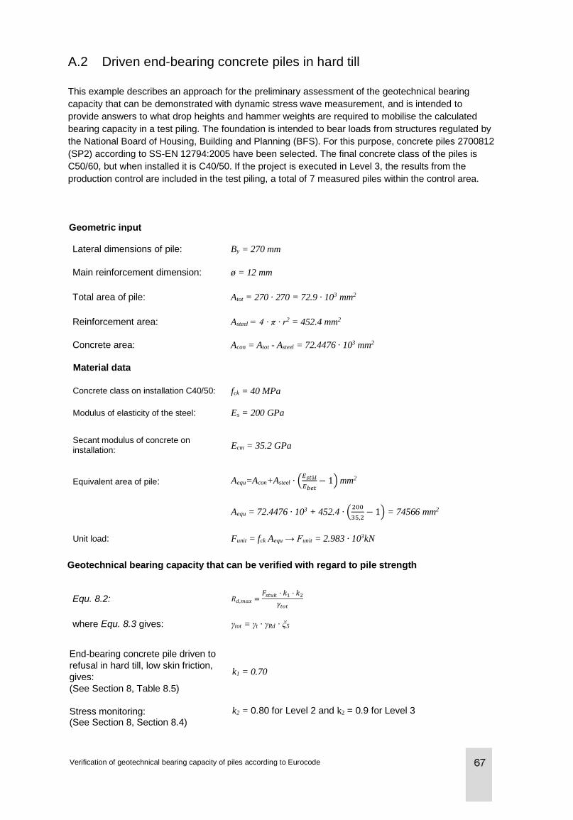
A.2 Driven end-bearing concrete piles in hard till
This example describes an approach for the preliminary assessment of the geotechnical bearing
capacity that can be demonstrated with dynamic stress wave measurement, and is intended to
provide answers to what drop heights and hammer weights are required to mobilise the calculated
bearing capacity in a test piling. The foundation is intended to bear loads from structures regulated by
the National Board of Housing, Building and Planning (BFS). For this purpose, concrete piles 2700812
(SP2) according to SS-EN 12794:2005 have been selected. The final concrete class of the piles is
C50/60, but when installed it is C40/50. If the project is executed in Level 3, the results from the
production control are included in the test piling, a total of 7 measured piles within the control area.
Geometric input
Lateral dimensions of pile: By = 270 mm
Main reinforcement dimension: ø = 12 mm
Total area of pile: Atot = 270 · 270 = 72.9 · 103 mm2
Reinforcement area: Asteel = 4 · π · r2 = 452.4 mm2
Concrete area: Acon = Atot - Asteel = 72.4476 · 103 mm2
Material data
Concrete class on installation C40/50: fck = 40 MPa
Modulus of elasticity of the steel: Es = 200 GPa
Secant modulus of concrete on installation:
Ecm = 35.2 GPa
Equivalent area of pile: Aequ=Acon+Asteel · (𝐸𝑠𝑡å𝑙
𝐸𝑏𝑒𝑡− 1) mm2
Aequ = 72.4476 · 103 + 452.4 · (200
35,2− 1) = 74566 mm2
Unit load: Funit = fck Aequ → Funit = 2.983 · 103kN
Geotechnical bearing capacity that can be verified with regard to pile strength
Equ. 8.2: 𝑅𝑑,𝑚𝑎𝑥 =𝐹𝑠𝑡𝑢𝑘 · 𝑘1 · 𝑘2
𝛾𝑡𝑜𝑡
where Equ. 8.3 gives: γtot = γt · γRd · ξ5
End-bearing concrete pile driven to
refusal in hard till, low skin friction,
gives:
(See Section 8, Table 8.5)
k1 = 0.70
Stress monitoring: (See Section 8, Section 8.4)
k2 = 0.80 for Level 2 and k2 = 0.9 for Level 3
Verification of geotechnical bearing capacity of piles according to Eurocode
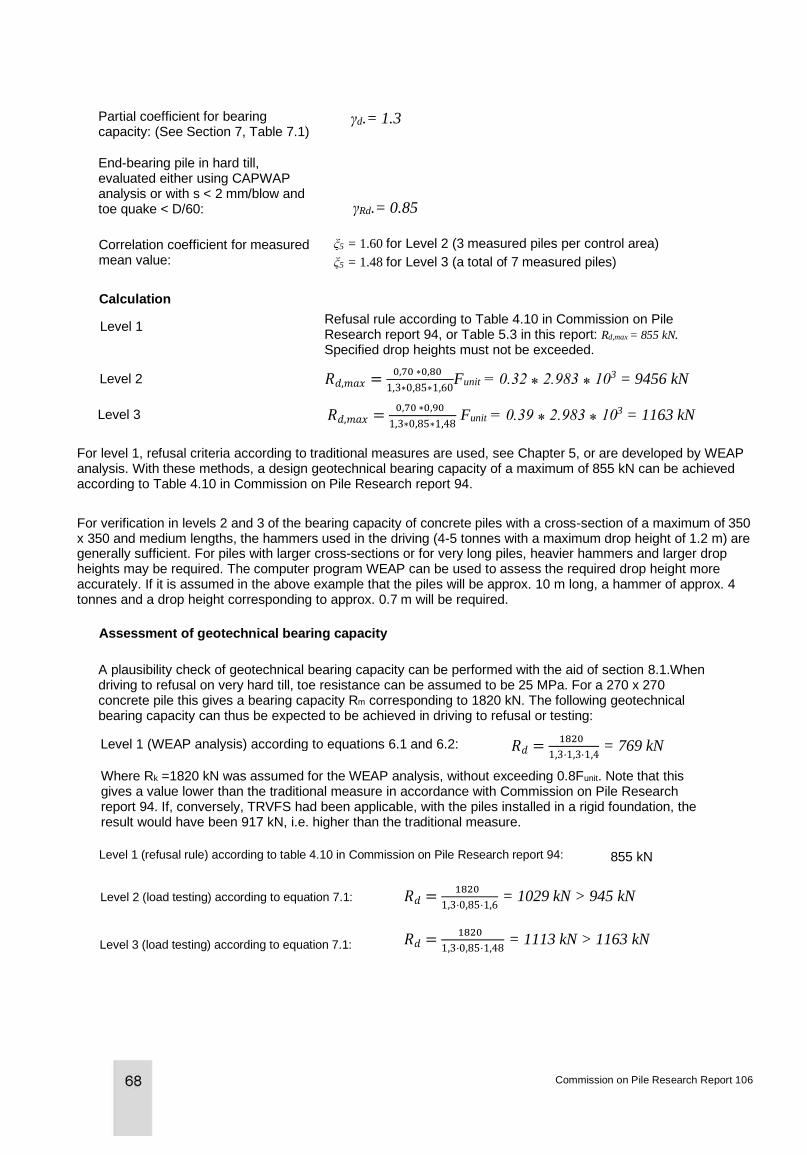
Partial coefficient for bearing capacity: (See Section 7, Table 7.1)
End-bearing pile in hard till, evaluated either using CAPWAP analysis or with s < 2 mm/blow and toe quake < D/60:
Correlation coefficient for measured mean value:
ξ5 = 1.60 for Level 2 (3 measured piles per control area)
ξ5 = 1.48 for Level 3 (a total of 7 measured piles)
Calculation
Level 2
Level 3
Refusal rule according to Table 4.10 in Commission on Pile Research report 94, or Table 5.3 in this report: Rd,max = 855 kN. Specified drop heights must not be exceeded.
For level 1, refusal criteria according to traditional measures are used, see Chapter 5, or are developed by WEAP analysis. With these methods, a design geotechnical bearing capacity of a maximum of 855 kN can be achieved according to Table 4.10 in Commission on Pile Research report 94.
For verification in levels 2 and 3 of the bearing capacity of concrete piles with a cross-section of a maximum of 350 x 350 and medium lengths, the hammers used in the driving (4-5 tonnes with a maximum drop height of 1.2 m) are generally sufficient. For piles with larger cross-sections or for very long piles, heavier hammers and larger drop heights may be required. The computer program WEAP can be used to assess the required drop height more accurately. If it is assumed in the above example that the piles will be approx. 10 m long, a hammer of approx. 4 tonnes and a drop height corresponding to approx. 0.7 m will be required.
Assessment of geotechnical bearing capacity
A plausibility check of geotechnical bearing capacity can be performed with the aid of section 8.1.When driving to refusal on very hard till, toe resistance can be assumed to be 25 MPa. For a 270 x 270 concrete pile this gives a bearing capacity Rm corresponding to 1820 kN. The following geotechnical bearing capacity can thus be expected to be achieved in driving to refusal or testing:
Level 1 (WEAP analysis) according to equations 6.1 and 6.2:
Where Rk =1820 kN was assumed for the WEAP analysis, without exceeding 0.8Funit. Note that this gives a value lower than the traditional measure in accordance with Commission on Pile Research report 94. If, conversely, TRVFS had been applicable, with the piles installed in a rigid foundation, the result would have been 917 kN, i.e. higher than the traditional measure.
Level 1 (refusal rule) according to table 4.10 in Commission on Pile Research report 94: 855 kN
Level 2 (load testing) according to equation 7.1:
Level 3 (load testing) according to equation 7.1:
Commission on Pile Research Report 106
Level 1
γd.= 1.3
γRd.= 0.85
𝑅𝑑,𝑚𝑎𝑥 =0,70 ∗0,80
1,3∗0,85∗1,60Funit = 0.32 ⁎ 2.983 ⁎ 103 = 9456 kN
𝑅𝑑,𝑚𝑎𝑥 =0,70 ∗0,90
1,3∗0,85∗1,48 Funit = 0.39 ⁎ 2.983 ⁎ 103 = 1163 kN
𝑅𝑑 =1820
1,3·0,85·1,6 = 1029 kN > 945 kN
𝑅𝑑 =1820
1,3·1,3·1,4 = 769 kN
𝑅𝑑 =1820
1,3·0,85·1,48 = 1113 kN > 1163 kN
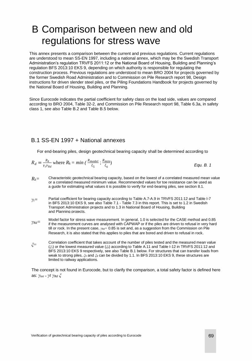
B Comparison between new and old regulations for stress wave measurement This annex presents a comparison between the current and previous regulations. Current regulations
are understood to mean SS-EN 1997, including a national annex, which may be the Swedish Transport Administration’s regulation TRVFS 2011:12 or the National Board of Housing, Building and Planning’s regulation BFS 2013:10 EKS 9, depending on which authority is responsible for regulating the construction process. Previous regulations are understood to mean BRO 2004 for projects governed by the former Swedish Road Administration and to Commission on Pile Research report 98, Design instructions for driven slender steel piles, or the Piling Foundations Handbook for projects governed by the National Board of Housing, Building and Planning.
Since Eurocode indicates the partial coefficient for safety class on the load side, values are compared according to BRO 2004, Table 32-2, and Commission on Pile Research report 98, Table 6.3a, in safety class 1, see also Table B.2 and Table B.5 below.
B.1 SS-EN 1997 + National annexes
For end-bearing piles, design geotechnical bearing capacity shall be determined according to
Equ. B. 1
Rk= Characteristic geotechnical bearing capacity, based on the lowest of a correlated measured mean value or a correlated measured minimum value. Recommended values for toe resistance can be used as a guide for estimating what values it is possible to verify for end-bearing piles, see section 8.1.
γt= Partial coefficient for bearing capacity according to Table A.7-A.9 in TRVFS 2011:12 and Table I-7 in BFS 2013:10 EKS 9, see also Table 7.1 - Table 7.3 in this report. This is set to 1.2 in Swedish Transport Administration projects and to 1.3 in National Board of Housing, Building and Planning projects.
γRd=
Model factor for stress wave measurement. In general, 1.0 is selected for the CASE method and 0.85 if the measurement curves are analysed with CAPWAP or if the piles are driven to refusal in very hard till or rock. In the present case, γRd= 0.85 is set and, as a suggestion from the Commission on Pile
Research, it is also stated that this applies to piles that are bored and driven to refusal in rock.
ξ=
Correlation coefficient that takes account of the number of piles tested and the measured mean value (ξ5) or the lowest measured value (ξ6) according to Table A.11 and Table I-12 in TRVFS 2011:12 and BFS 2013:10 EKS 9 respectively, see also Table B.1 below. For structures that can transfer loads from weak to strong piles, ξ5 and ξ6 can be divided by 1.1. In BFS 2013:10 EKS 9, these structures are limited to railway applications.
The concept is not found in Eurocode, but to clarify the comparison, a total safety factor is defined here
as: γtot = γt γRd ξ
Verification of geotechnical bearing capacity of piles according to Eurocode
𝑅𝑑 =𝑅𝑘
𝛾𝑡𝛾𝑅𝑑 where Rk = min (
𝑅𝑚𝑒𝑑𝑒𝑙
𝜉5 ;
𝑅𝑚𝑖𝑛
𝜉6)
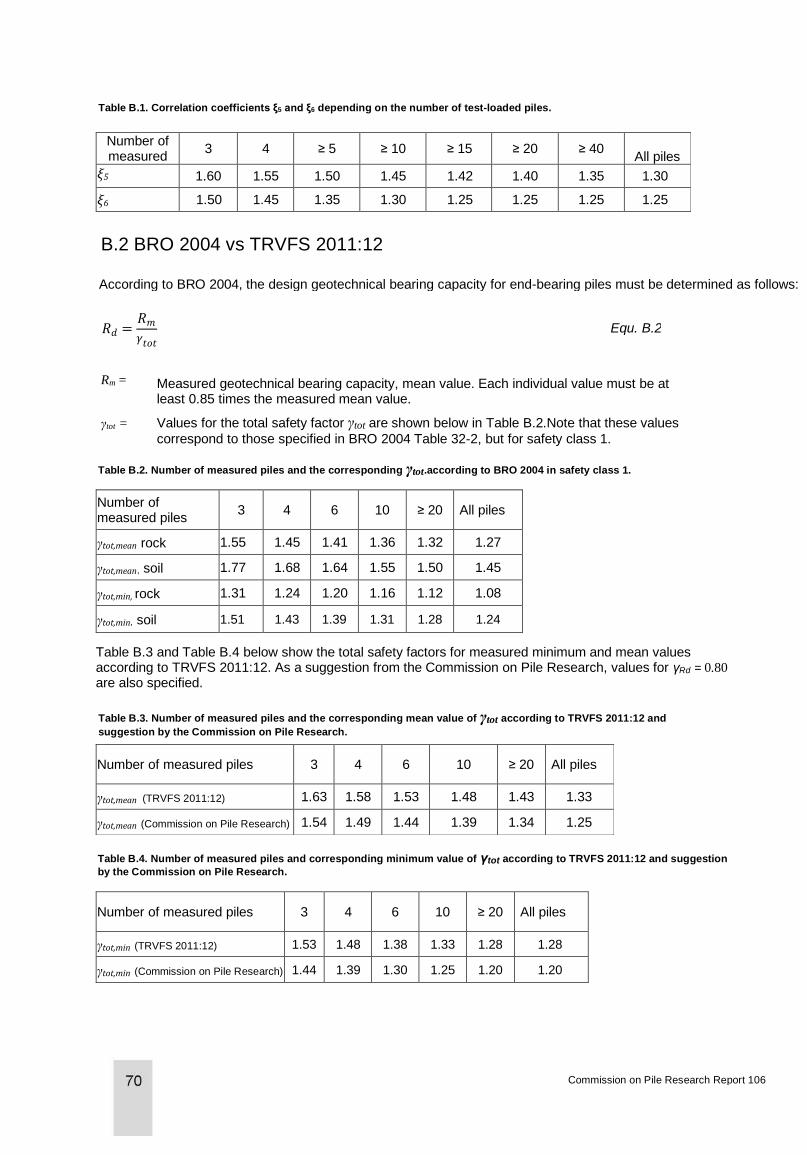
Table B.1. Correlation coefficients ξ5 and ξ6 depending on the number of test-loaded piles.
Number of measured
piles
3 4 ≥ 5 ≥ 10 ≥ 15 ≥ 20 ≥ 40 All piles
ξ5 1.60 1.55 1.50 1.45 1.42 1.40 1.35 1.30
ξ6 1.50 1.45 1.35 1.30 1.25 1.25 1.25 1.25
B.2 BRO 2004 vs TRVFS 2011:12
According to BRO 2004, the design geotechnical bearing capacity for end-bearing piles must be determined as follows:
Equ. B.2 𝑅𝑑 =𝑅𝑚
𝛾𝑡𝑜𝑡
Rm = Measured geotechnical bearing capacity, mean value. Each individual value must be at least 0.85 times the measured mean value.
γtot = Values for the total safety factor γtot are shown below in Table B.2.Note that these values
correspond to those specified in BRO 2004 Table 32-2, but for safety class 1.
Table B.2. Number of measured piles and the corresponding γtot.according to BRO 2004 in safety class 1.
Number of measured piles
3 4 6 10 ≥ 20 All piles
γtot,mean rock 1.55 1.45 1.41 1.36 1.32 1.27
γtot,mean, soil 1.77 1.68 1.64 1.55 1.50 1.45
γtot,min, rock 1.31 1.24 1.20 1.16 1.12 1.08
γtot,min, soil 1.51 1.43 1.39 1.31 1.28 1.24
Table B.3 and Table B.4 below show the total safety factors for measured minimum and mean values according to TRVFS 2011:12. As a suggestion from the Commission on Pile Research, values for γRd = 0.80 are also specified.
Table B.3. Number of measured piles and the corresponding mean value of γtot according to TRVFS 2011:12 and
suggestion by the Commission on Pile Research.
Number of measured piles 3 4 6 10 ≥ 20 All piles
γtot,mean (TRVFS 2011:12) 1.63 1.58 1.53 1.48 1.43 1.33
γtot,mean (Commission on Pile Research) 1.54 1.49 1.44 1.39 1.34 1.25
Table B.4. Number of measured piles and corresponding minimum value of γtot according to TRVFS 2011:12 and suggestion
by the Commission on Pile Research.
Number of measured piles 3 4 6 10 ≥ 20 All piles
γtot,min (TRVFS 2011:12) 1.53 1.48 1.38 1.33 1.28 1.28
γtot,min (Commission on Pile Research) 1.44 1.39 1.30 1.25 1.20 1.20
Commission on Pile Research Report 106
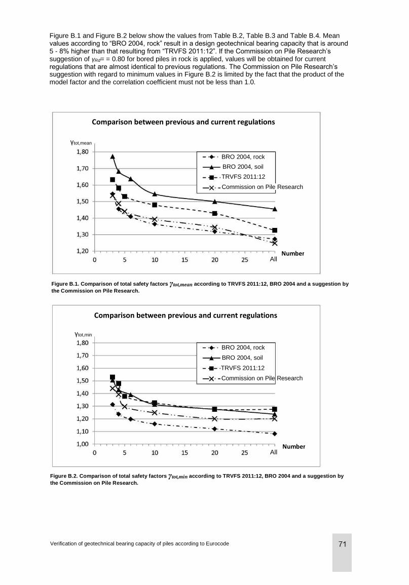
Figure B.1 and Figure B.2 below show the values from Table B.2, Table B.3 and Table B.4. Mean values according to “BRO 2004, rock” result in a design geotechnical bearing capacity that is around 5 - 8% higher than that resulting from “TRVFS 2011:12”. If the Commission on Pile Research’s suggestion of γRd= = 0.80 for bored piles in rock is applied, values will be obtained for current regulations that are almost identical to previous regulations. The Commission on Pile Research’s suggestion with regard to minimum values in Figure B.2 is limited by the fact that the product of the model factor and the correlation coefficient must not be less than 1.0.
Comparison between previous and current regulations
BRO 2004, rock
BRO 2004, soil
TRVFS 2011:12
Commission on Pile Research
γtot,mean
All Number
Figure B.1. Comparison of total safety factors γtot,mean according to TRVFS 2011:12, BRO 2004 and a suggestion by
the Commission on Pile Research.
Comparison between previous and current regulations
BRO 2004, rock
BRO 2004, soil
TRVFS 2011:12
Commission on Pile Research
γtot,min
All Number
Figure B.2. Comparison of total safety factors γtot,min according to TRVFS 2011:12, BRO 2004 and a suggestion by
the Commission on Pile Research.
Verification of geotechnical bearing capacity of piles according to Eurocode
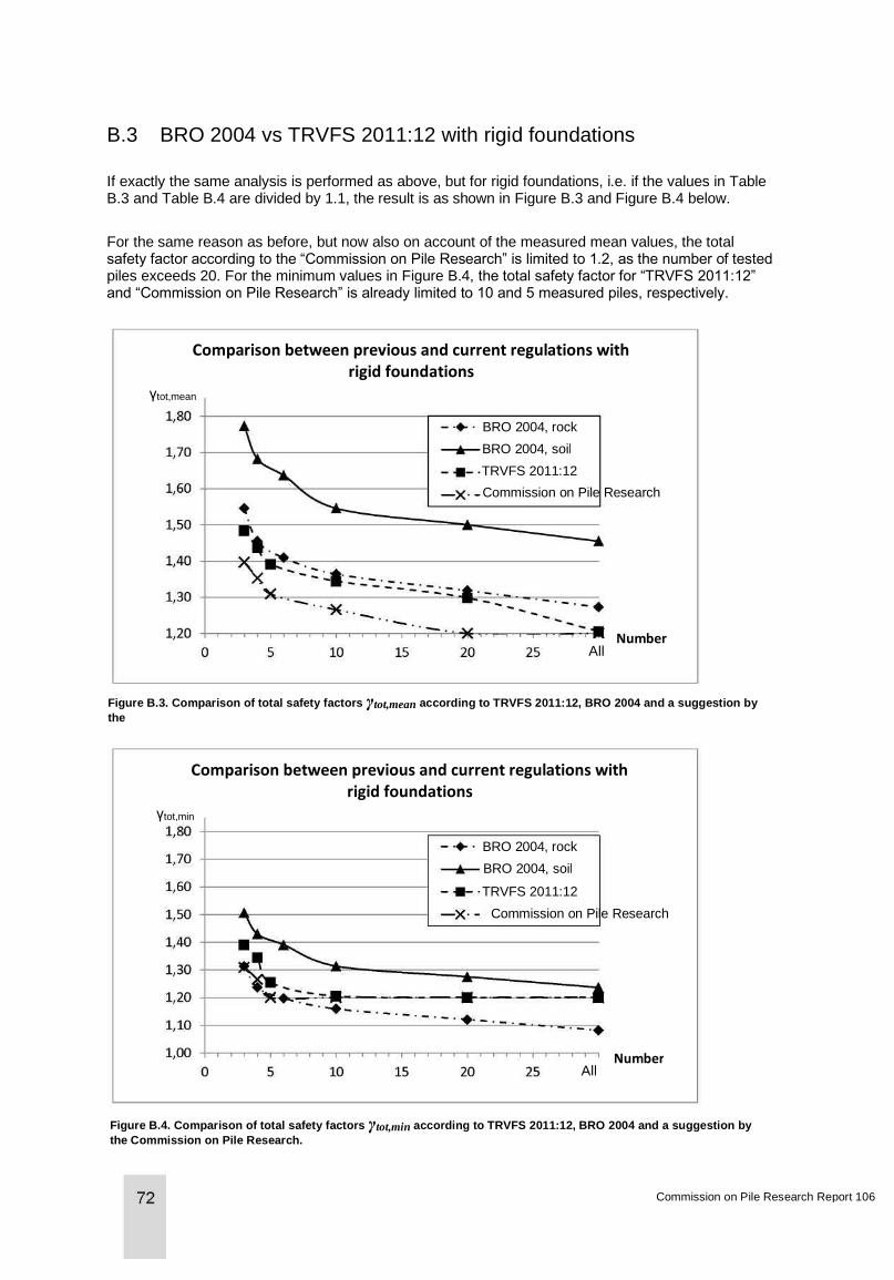
B.3 BRO 2004 vs TRVFS 2011:12 with rigid foundations
If exactly the same analysis is performed as above, but for rigid foundations, i.e. if the values in Table B.3 and Table B.4 are divided by 1.1, the result is as shown in Figure B.3 and Figure B.4 below.
For the same reason as before, but now also on account of the measured mean values, the total safety factor according to the “Commission on Pile Research” is limited to 1.2, as the number of tested piles exceeds 20. For the minimum values in Figure B.4, the total safety factor for “TRVFS 2011:12” and “Commission on Pile Research” is already limited to 10 and 5 measured piles, respectively.
Comparison between previous and current regulations with rigid foundations
γtot,mean
BRO 2004, rock
BRO 2004, soil
TRVFS 2011:12
Commission on Pile Research
Figure B.3. Comparison of total safety factors γtot,mean according to TRVFS 2011:12, BRO 2004 and a suggestion by
the
Commission on Pile Research.
Comparison between previous and current regulations with rigid foundations
γtot,min
BRO 2004, rock
BRO 2004, soil
TRVFS 2011:12
Commission on Pile Research
Number All
Figure B.4. Comparison of total safety factors γtot,min according to TRVFS 2011:12, BRO 2004 and a suggestion by
the Commission on Pile Research.
Commission on Pile Research Report 106
All Number
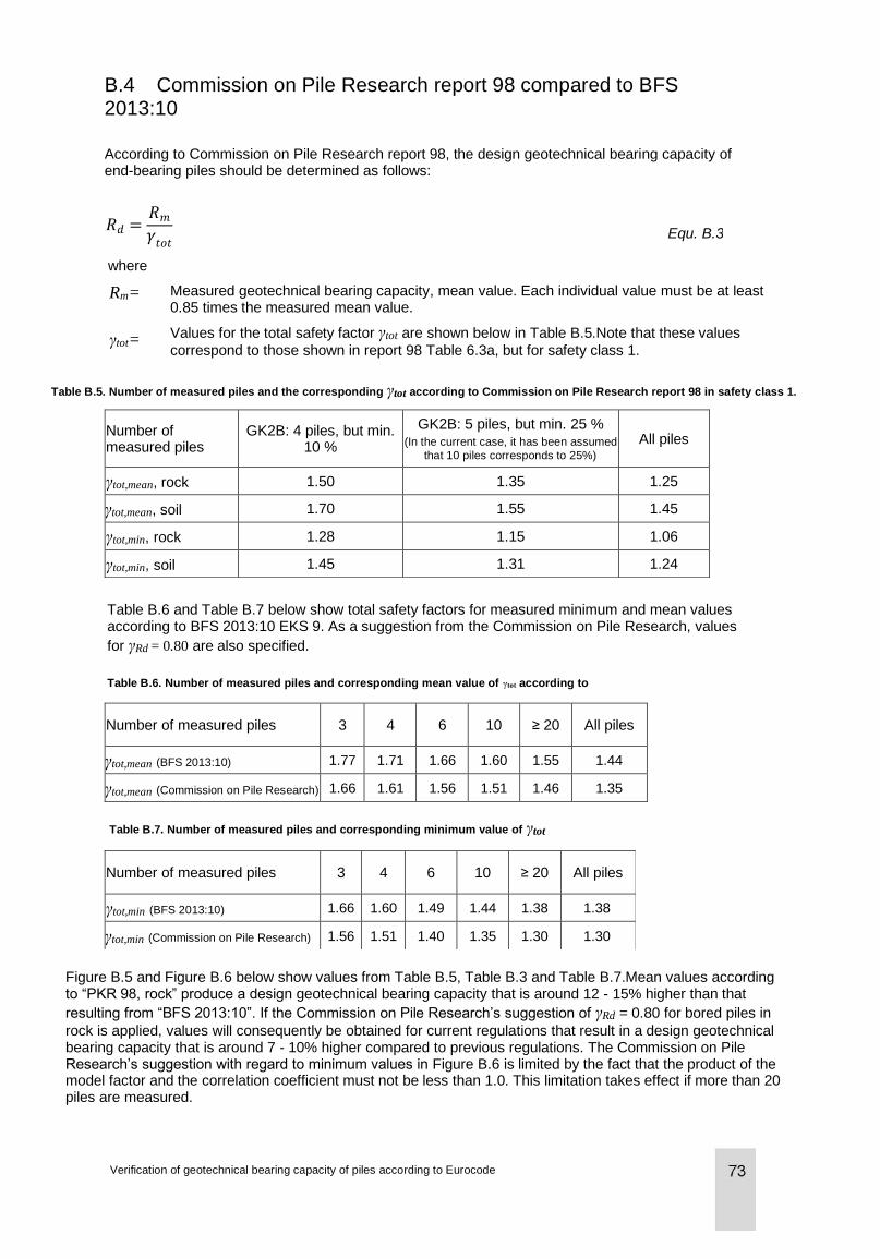
B.4 Commission on Pile Research report 98 compared to BFS 2013:10
According to Commission on Pile Research report 98, the design geotechnical bearing capacity of end-bearing piles should be determined as follows:
Equ. B.3
where
Rm= Measured geotechnical bearing capacity, mean value. Each individual value must be at least 0.85 times the measured mean value.
γtot= Values for the total safety factor γtot are shown below in Table B.5.Note that these values
correspond to those shown in report 98 Table 6.3a, but for safety class 1.
Table B.5. Number of measured piles and the corresponding γtot according to Commission on Pile Research report 98 in safety class 1.
Number of measured piles
GK2B: 4 piles, but min. 10 %
GK2B: 5 piles, but min. 25 % (In the current case, it has been assumed
that 10 piles corresponds to 25%)
All piles
γtot,mean, rock 1.50 1.35 1.25
γtot,mean, soil 1.70 1.55 1.45
γtot,min, rock 1.28 1.15 1.06
γtot,min, soil 1.45 1.31 1.24
Table B.6 and Table B.7 below show total safety factors for measured minimum and mean values according to BFS 2013:10 EKS 9. As a suggestion from the Commission on Pile Research, values
for γRd = 0.80 are also specified.
Table B.6. Number of measured piles and corresponding mean value of γtot according to
BFS 2013:10.
Number of measured piles 3 4 6 10 ≥ 20 All piles
γtot,mean (BFS 2013:10) 1.77 1.71 1.66 1.60 1.55 1.44
γtot,mean (Commission on Pile Research) 1.66 1.61 1.56 1.51 1.46 1.35
Table B.7. Number of measured piles and corresponding minimum value of γtot
according to BFS 2013:10.
Number of measured piles 3 4 6 10 ≥ 20 All piles
γtot,min (BFS 2013:10) 1.66 1.60 1.49 1.44 1.38 1.38
γtot,min (Commission on Pile Research) 1.56 1.51 1.40 1.35 1.30 1.30
Figure B.5 and Figure B.6 below show values from Table B.5, Table B.3 and Table B.7.Mean values according to “PKR 98, rock” produce a design geotechnical bearing capacity that is around 12 - 15% higher than that
resulting from “BFS 2013:10”. If the Commission on Pile Research’s suggestion of γRd = 0.80 for bored piles in
rock is applied, values will consequently be obtained for current regulations that result in a design geotechnical bearing capacity that is around 7 - 10% higher compared to previous regulations. The Commission on Pile Research’s suggestion with regard to minimum values in Figure B.6 is limited by the fact that the product of the model factor and the correlation coefficient must not be less than 1.0. This limitation takes effect if more than 20 piles are measured.
Verification of geotechnical bearing capacity of piles according to Eurocode
𝑅𝑑 =𝑅𝑚
𝛾𝑡𝑜𝑡
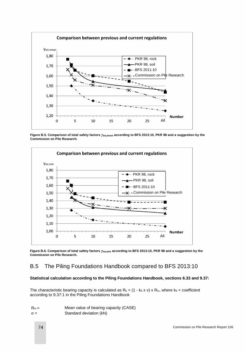
Comparison between previous and current regulations
PKR 98, rock
PKR 98, soil
BFS 2011:10
Commission on Pile Research
γtot,mean
Figure B.5. Comparison of total safety factors γtot,mean according to BFS 2013:10, PKR 98 and a suggestion by the
Commission on Pile Research.
Comparison between previous and current regulations
PKR 98, rock
PKR 98, soil
BFS 2011:10
Commission on Pile Research
γtot,min
Figure B.6. Comparison of total safety factors γtot,min according to BFS 2013:10, PKR 98 and a suggestion by the
Commission on Pile Research.
B.5 The Piling Foundations Handbook compared to BFS 2013:10
Statistical calculation according to the Piling Foundations Handbook, sections 6.33 and 9.37:
The characteristic bearing capacity is calculated as Rk = (1 - k5 x v) x Rm, where k5 = coefficient according to 9.37:1 in the Piling Foundations Handbook
Rm = Mean value of bearing capacity (CASE) in kN σ = Standard deviation (kN)
Commission on Pile Research Report 106
All Number
Number All
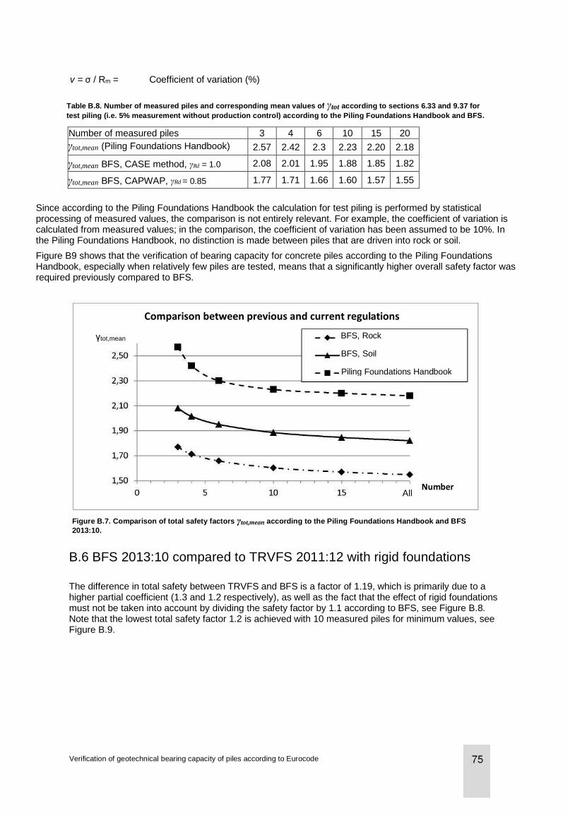
v = σ / Rm = Coefficient of variation (%)
Table B.8. Number of measured piles and corresponding mean values of γtot according to sections 6.33 and 9.37 for
test piling (i.e. 5% measurement without production control) according to the Piling Foundations Handbook and BFS.
Number of measured piles 3 4 6 10 15 20
γtot,mean (Piling Foundations Handbook) 2.57 2.42 2.3 2.23 2.20 2.18
γtot,mean BFS, CASE method, γRd = 1.0 2.08 2.01 1.95 1.88 1.85 1.82
γtot,mean BFS, CAPWAP, γRd = 0.85 1.77 1.71 1.66 1.60 1.57 1.55
Since according to the Piling Foundations Handbook the calculation for test piling is performed by statistical processing of measured values, the comparison is not entirely relevant. For example, the coefficient of variation is calculated from measured values; in the comparison, the coefficient of variation has been assumed to be 10%. In the Piling Foundations Handbook, no distinction is made between piles that are driven into rock or soil.
Figure B9 shows that the verification of bearing capacity for concrete piles according to the Piling Foundations Handbook, especially when relatively few piles are tested, means that a significantly higher overall safety factor was required previously compared to BFS.
γtot,mean
Comparison between previous and current regulations
BFS, Rock
BFS, Soil
Piling Foundations Handbook
Figure B.7. Comparison of total safety factors γtot,mean according to the Piling Foundations Handbook and BFS
2013:10.
All Number
B.6 BFS 2013:10 compared to TRVFS 2011:12 with rigid foundations
The difference in total safety between TRVFS and BFS is a factor of 1.19, which is primarily due to a higher partial coefficient (1.3 and 1.2 respectively), as well as the fact that the effect of rigid foundations must not be taken into account by dividing the safety factor by 1.1 according to BFS, see Figure B.8. Note that the lowest total safety factor 1.2 is achieved with 10 measured piles for minimum values, see Figure B.9.
Verification of geotechnical bearing capacity of piles according to Eurocode
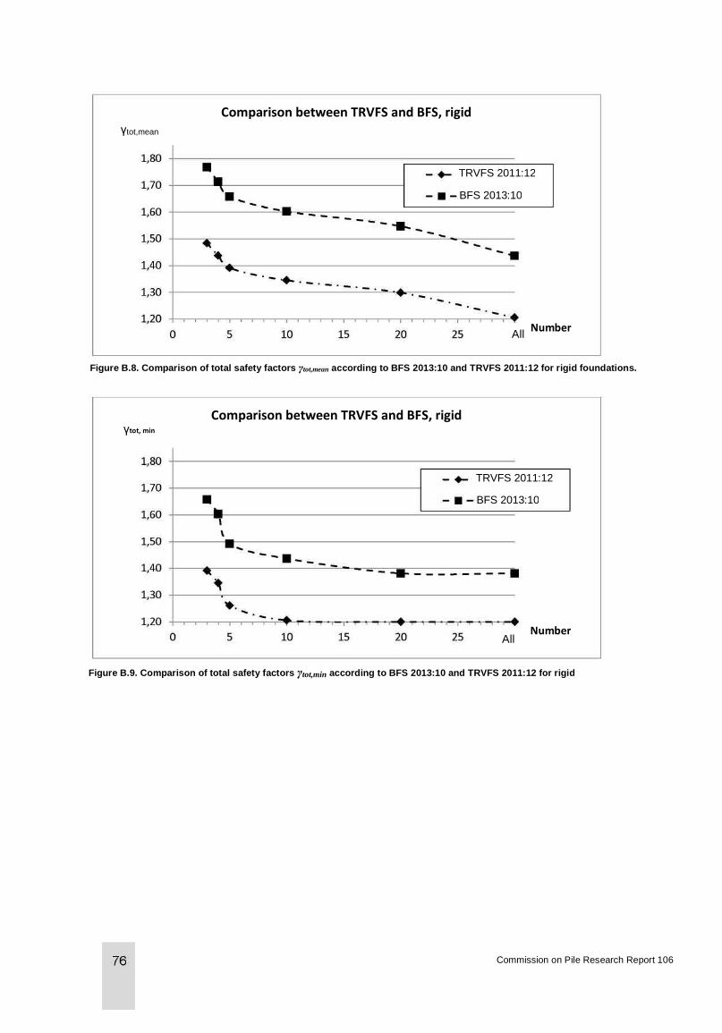
Comparison between TRVFS and BFS, rigid foundations
TRVFS 2011:12
BFS 2013:10
Figure B.8. Comparison of total safety factors γtot,mean according to BFS 2013:10 and TRVFS 2011:12 for rigid foundations.
Comparison between TRVFS and BFS, rigid foundations γtot, min
TRVFS 2011:12
BFS 2013:10
Figure B.9. Comparison of total safety factors γtot,min according to BFS 2013:10 and TRVFS 2011:12 for rigid
foundations.
Commission on Pile Research Report 106
All Number
Number All
γtot,mean

Feb
ruary
201
4
Co
mm
issio
n o
n P
ile R
esearc
h,
c/o
Bra
nschkanslie
t,
Box 2
2307,
104 2
2 S
tockholm
,
ww
w.p
alk
om
mis
sio
nen.o
rg
In September 1959, the Pile
Committee for pile driving and
pile bearing capacity was
formed.
The Commission’s activities are based on the needs
of society and the industry for research and
information in the field of piling. Its members consist
of contractors, manufacturers, consultants,
researchers, municipalities and representatives from
various public authorities. The Commission on Pile
Research, which brings these groups together, is
unique in Europe.
Further information on the
activities and membership of the
Commission on Pile Research is
available from the Commission
Secretary.
PÅLKOMMISSIONEN