Embed Size (px)
Citation preview

1 Version SolidPlant 2016
2
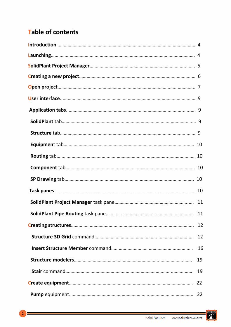
Table of contents
Introduction………………………………………………………………………………………………… 4
Launching……………………………………………………………………………………………………. 4
SolidPlant Project Manager…………………………………………………………………..……. 5
Creating a new project………………………………………………………………………………… 6
Open project……………………………………………………………………………………………….. 7
User interface...…………………………………………………………………………………………… 9
Application tabs..………………………………………………………………………………..…..…. 9
SolidPlant tab……………………………………………………………………………………….….… 9
Structure tab……………………………………………………………………………………….……… 9
Equipment tab……………………………………………………………………………………..…… 10
Routing tab……………………………………………………………………………..………………… 10
Component tab……………………………………………………………………..………………….. 10
SP Drawing tab……………………………………………………………………….….…………….. 10
Task panes……………………………………………………………………………………………..….. 10
SolidPlant Project Manager task pane…………………………………………………..…. 11
SolidPlant Pipe Routing task pane………….…………………………………………….….. 11
Creating structures…………………………………………………………………………………….. 12
Structure 3D Grid command…………………………………………..…………………….…. 12
Insert Structure Member command……………………………………………..………… 16
Structure modelers…………………………………………………………..……………….……. 19
Stair command…………………………………………………………………………..…………… 19
Create equipment……………………………………………………………………………………… 22
Pump equipment……………………………………………………….…………………………….. 22
3
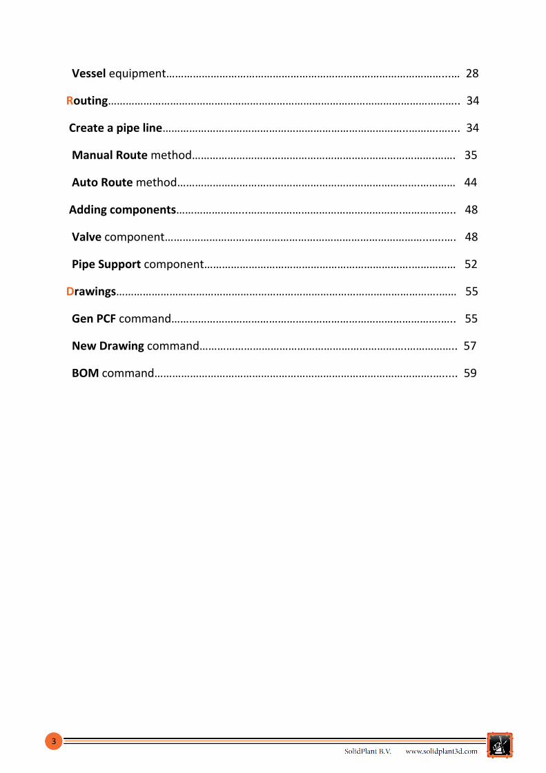
Vessel equipment…………………………………………………………………………………...… 28
Routing……………………………………………………………………………………………………….. 34
Create a pipe line………………………………………………………………………..……….….... 34
Manual Route method……………………………………………………………………….……. 35
Auto Route method……………………………………………………………………….………… 44
Adding components…………………...…………………………………………….………….….. 48
Valve component……………………………………………………………………………..…..…. 48
Pipe Support component…………………………………………………………….…………… 52
Drawings……………………………………………………………………………………………….…… 55
Gen PCF command……………………………………………………………………………….….. 55
New Drawing command…………………………………………………………….…………….. 57
BOM command………………………………………………………………………………….…..... 59
4
Introduction
The purpose of this document is to teach new users the fundamentals of SolidPlant3D and assist
them with the main features.
SolidPlant 3D is an add-in on top of SOLIDWORKS standard edition which allows the designers to
quickly create intelligent 3D process plant designs driven by specifications, and deliver easily de
facto standard isometric drawings (which is Isogen®, the Alias solution embedded in SolidPlant 3D).
SolidPlant 3D is a database driven system and provides an application called SpecCreator for the
generation of the piping specifications, with a wide range of catalogues to build up the needed
piping components for the project.
Launching
Solidplant 3D can be launched in three different ways.
From the desktop shortcut.
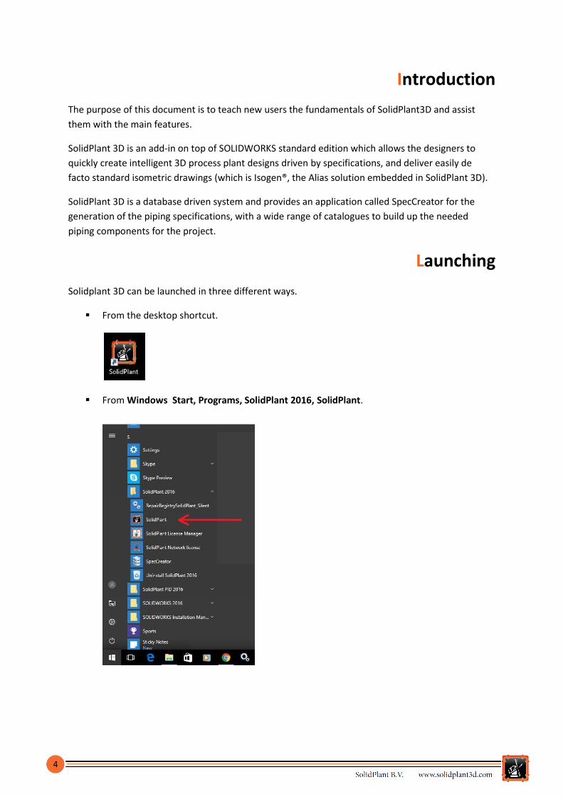
From Windows Start, Programs, SolidPlant 2016, SolidPlant.

5
From SolidWorks, Tools, Add-ins, select the Active Add-ins check box SolidPlant.
SolidPlant Project Manager
On starting SolidPlant the SolidPlant Project Manager task pane will be automatically displayed by
default on the right hand side of the screen. Through this interface it is possible to create new
projects, open existing projects and create copies of projects.

6
Creating a new project
In SolidPlant 3D, the projects are assemblies of SOLIDWORKS consisting of many components, which
can be parts or other assemblies, called subassemblies. The pipe lines and equipment created with
SolidPlant 3D are subassemblies and the structure models can be parts or subassemblies.
1. Click New project… command.
To create a new project with SolidPlant 3D,
click SolidPlant Project Manager task pane >
New project… .
When prompted the Create new project dialog box, the user can define the fields Project Name,
Project Description and Directory, where the project will be located.
On Project Unit area is displayed the three different types of system of units in which a project can
be defined. Once the project has been created, the project unit can´t be changed anymore.
Option Description
Imperial Imperial system of unit
Metric International system of unit
Mix-Metric A combination of imperial and metric units. Nominal diameter is on imperial unit and the rest of the values are on metric unit (length, weight, etc.)
2. Define the project properties.
Add the values on below for the property fields and option required. .
Project Name: Type Project 01.
Project Description: Type Getting Started
Project.
Directory: C:\ProgramData\SolidPlant Projects
Project Unit: Select option Mix-Metric.

7
3. Click Create and the project assembly will be displayed.
4. Click Save on the Standard toolbar.
Open a project
There are two ways to open a project.
From the dropdown menu Active Project, it will list all the projects created previously.
Select a project name and it will be opened.
Click SolidPlant Project Manager task pane > Open project… .
When prompted the browse window, the project can be opened via two different types of
files within the project folder. It doesn´t matter which type of file the user chooses that the
project will be opened.
By default the project folder is located in C:\ProgramData\SolidPlant Projects.

8
Via.mdf file.
SolidPlant 3D is a database driven system and uses Microsoft SQL Server 2014 as a
relational database management system. The .mdf file of the project is used by
Microsoft SQL Server for storing the database files and Schema.
Browse into the project folder that we have created previously, select Project
01.mdf file and click Open .
Via .SDASM file.
The .SDASM file is the SOLIDWORKS assembly document, so that the project can be
opened from the project assembly as well.
Select Project 01.SDASM file located in the Drawing folder within the project
folder, and click Open .

9
Automatically, once the project has been opened, it will be list on the dropdown menu
Active Project on the task pane SolidPlant Project Manager.
User Interface
The SolidPlant 3D user interface is fully integrated within SOLIDWORKS interface. SolidPlant 3D has
added two side Task Panes on the right hand side, and six Application Tabs on the top side in the
CommandManager menu of SOLIDWORKS.
Application tabs
There are six tabs available in SolidPlant 3D on the CommandManager of SOLIDWORKS that is a
context-sensitive toolbar. When you click a tab below the CommandManager, it dynamically updates
based on the toolbar the user wants to access.
SolidPlant tab
Provides a number of commands related to the management of the project, different views, access to SpecCreator application, project reports...
Structure tab This toolbar includes commands to create structure 3D grids, insert structure profiles, automatic generation of structure models (stairs, ladders, platforms, handrails, etc.), cutting list report…

10
Equipment tab This toolbar includes commands to create equipment from the SolidPlant libraries, convert equipment, edit equipment, management of the equipment nozzles, creation of linear and circular patterns… Routing tab This toolbar contains all the tools necessary to create and edit the pipe lines, as well as commands to add pipe supports and valve operators, component properties…
Component tab Provides a number of commands related to the piping components (elbow, flange, tee, instrument, valve, etc.), stub-in… SP Drawing tab The last toolbar includes the automatic generation of isometric drawings, commands to create different type of drawings, bill of material, TAG annotations...
Task Panes
There are two task panes available in SolidPlant 3D on the Task Pane of SOLIDWORKS on the right
hand side of the interface. Selecting any of the SolidPlant tabs, the task pane dynamically updates
according to the users´ needs .
When opening a project in SolidPlant 3D, all the commands and features of the two SolidPlant
task panes will be dynamically updated and made available.
When there is no project opened, just a few commands on the SolidPlant Project Manager
pane will be available.

11
SolidPlant Project Manager task pane
When opening a project, the number of commands available is
automatically updated in order to provide the tools to manage
the project.
The node tree Document List is displaying all the tags of the
components and the documentation generated in the project
sorted by type.
Type Components
Pipe Routing Pipe lines.
Equipment: Pumps, Exchangers …
Nozzle Nozzle Equipment.
Valve Valves and Control valves.
Extra Strainers, Spacers…
Instrument Gauges, Thermowells..
Pipe Support Pipe Supports.
GA Drawing .SLDDRW files.
Isometric Drawing .PCF, .DWG, .SLDDRW files.
Document .XLS, .docx, .PDF files…
There are three different colors which are showing the status of each tag in the
project.
Red: Just the data value is in the project database.
Blue: There is a 3D model created ready to bring into the project.
Black: The component is in the project assembly.
SolidPlant Pipe Routing task pane
This interface is divided up into four main sections providing the tools to create pipe lines as well as
to edit the values of the active pipe line, etc.
12
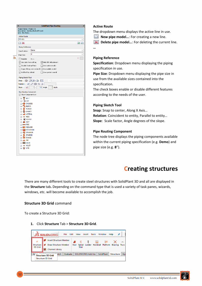
Active Route
The dropdown menu displays the active line in use.
New pipe model…: For creating a new line.
Delete pipe model…: For deleting the current line.
…
Piping Reference
Specification: Dropdown menu displaying the piping
specification in use.
Pipe Size: Dropdown menu displaying the pipe size in
use from the available sizes contained into the
specification.
The check boxes enable or disable different features
according to the needs of the user.
Piping Sketch Tool
Snap: Snap to center, Along X Axis…
Relation: Coincident to entity, Parallel to entity…
Slope: Scale factor, Angle degrees of the slope.
Pipe Routing Component
The node tree displays the piping components available
within the current piping specification (e.g. Demo) and
pipe size (e.g. 8”).
Creating structures
There are many different tools to create steel structures with SolidPlant 3D and all are displayed in
the Structure tab. Depending on the command type that is used a variety of task panes, wizards,
windows, etc. will become available to accomplish the job.
Structure 3D Grid command
To create a Structure 3D Grid:
1. Click Structure Tab > Structure 3D Grid.
13
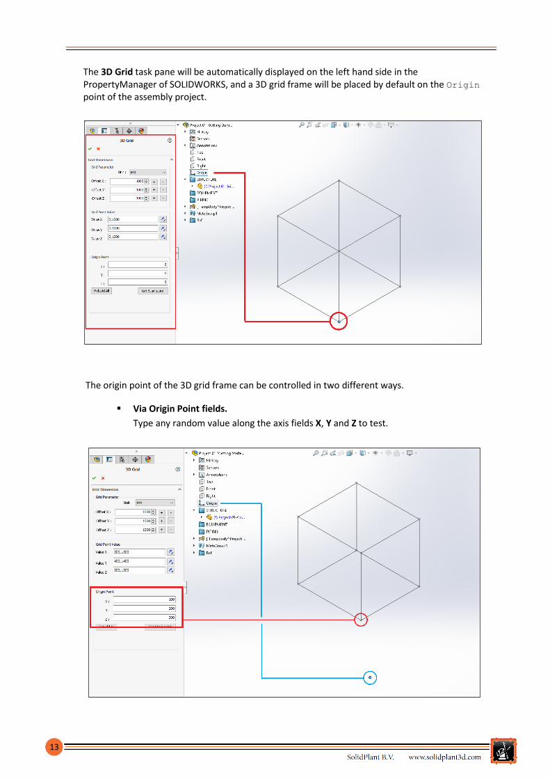
The 3D Grid task pane will be automatically displayed on the left hand side in the PropertyManager of SOLIDWORKS, and a 3D grid frame will be placed by default on the Origin point of the assembly project.
The origin point of the 3D grid frame can be controlled in two different ways.
Via Origin Point fields.
Type any random value along the axis fields X, Y and Z to test.
14
In order to update the 3D grid entity with the new values added into the parameter fields,
after typing the value, the user must click on any other field within the 3D Grid pane and
automatically the grid entity will be updated.
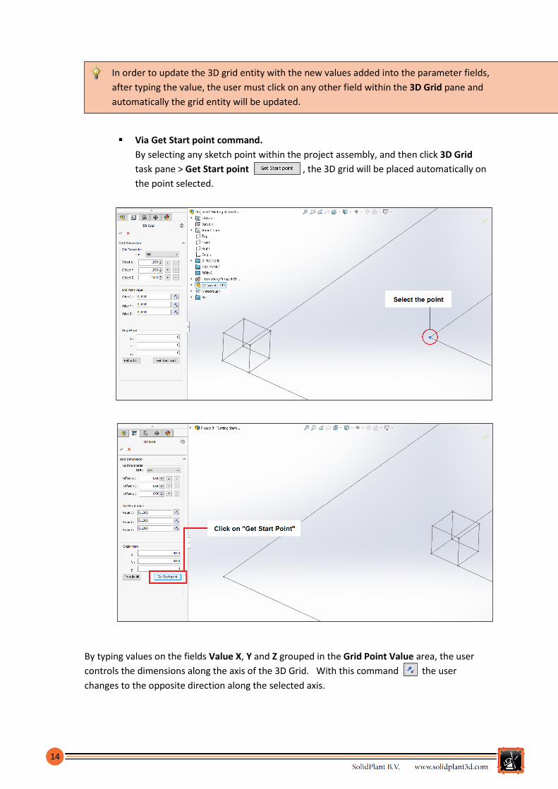
Via Get Start point command.
By selecting any sketch point within the project assembly, and then click 3D Grid
task pane > Get Start point , the 3D grid will be placed automatically on
the point selected.
By typing values on the fields Value X, Y and Z grouped in the Grid Point Value area, the user
controls the dimensions along the axis of the 3D Grid. With this command the user
changes to the opposite direction along the selected axis.
15
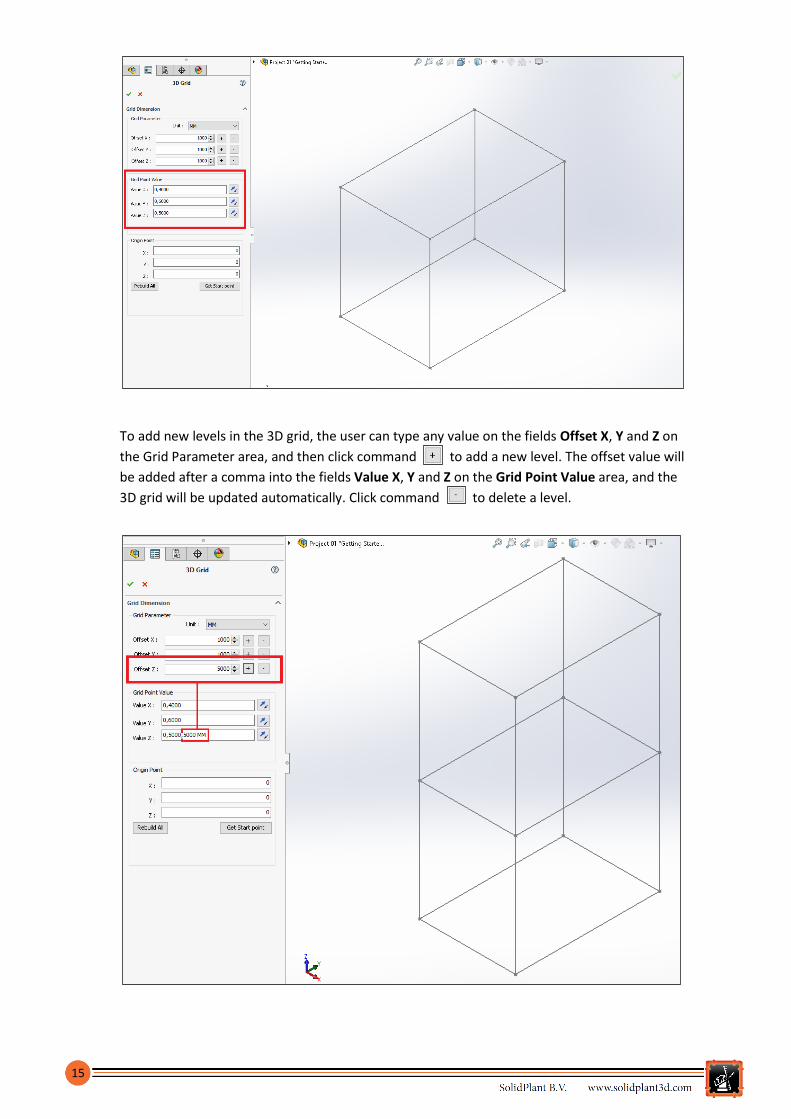
To add new levels in the 3D grid, the user can type any value on the fields Offset X, Y and Z on
the Grid Parameter area, and then click command to add a new level. The offset value will
be added after a comma into the fields Value X, Y and Z on the Grid Point Value area, and the
3D grid will be updated automatically. Click command to delete a level.

16
Also the user can change manually the values in the fields Value X, Y and Z on the Grid Point
Value area.
Add new levels by typing a comma after any value and type a new value of the level.
Delete manually any level by suppressing its value.
Edit any level by changing the value of an existing one.
2. Add the values on the Grid Point Value fields.
Type the values on below to define the 3D grid entity.
Value X: 0, 4000
Value Y: 0, 6000
Value Z: 0, 5000, 5000
3. Click 3D Grid task pane > OK to confirm and close the pane.
To edit again the 3D grid created.
Click on any sketch line of the grid and then click Structure Tab > Structure 3D Grid. The 3D Grid
pane will be displayed again for further editing.
Insert Structure Member command
To insert structure profiles:
1. Select any sketch line.
Select any sketch line contained into the 3D grid previously created.

17
2. Click Structure Tab > Insert Structure Member.
The Structural Member task pane will be automatically displayed on the left hand side in the
PropertyManager of SOLIDWORKS. SolidPlant 3D provides, apart from what is already in
SOLIDWORKS, a new wide range of standards, types of profiles and sizes of structural members.
The user can define the profile of the structure from the dropdown menus Standard, Type and
Size in the Selections area.
The SolidPlant weldment profiles are located in:
C:\Program Files\SolidPlant\Structure\Weldment Profiles.
By selecting the sketch lines, the profiles will be added automatically. All structural members in a
single group must use the same profile.
3. Define the values of the weldment profile.
Select the values on next page from the dropdown menus.

18
Menu Standard: Select ANSI Inch Standard.
Menu Type: Select W Section – Configured.
Menu Size: Select W10X88.
4. Select the vertical sketch lines.
Select all the vertical lines one by one in order to add the columns into the 3D grid.
5. Click Structure Member task pane > Ok to confirm.
6. Add also the structure beams using the same procedure.
7. Click Edit Mode symbol to exit once the structure is finished.
19
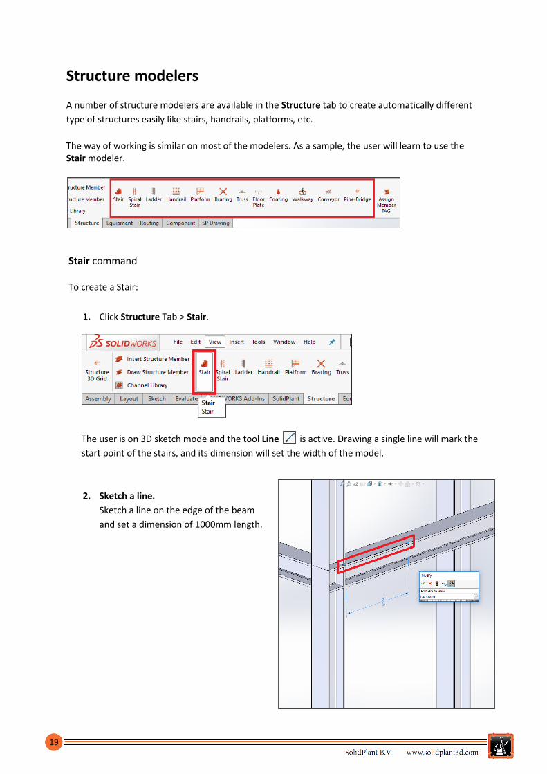
Structure modelers A number of structure modelers are available in the Structure tab to create automatically different
type of structures easily like stairs, handrails, platforms, etc.
The way of working is similar on most of the modelers. As a sample, the user will learn to use the Stair modeler.
Stair command To create a Stair:
1. Click Structure Tab > Stair.
The user is on 3D sketch mode and the tool Line is active. Drawing a single line will mark the
start point of the stairs, and its dimension will set the width of the model.
2. Sketch a line.
Sketch a line on the edge of the beam
and set a dimension of 1000mm length.
20
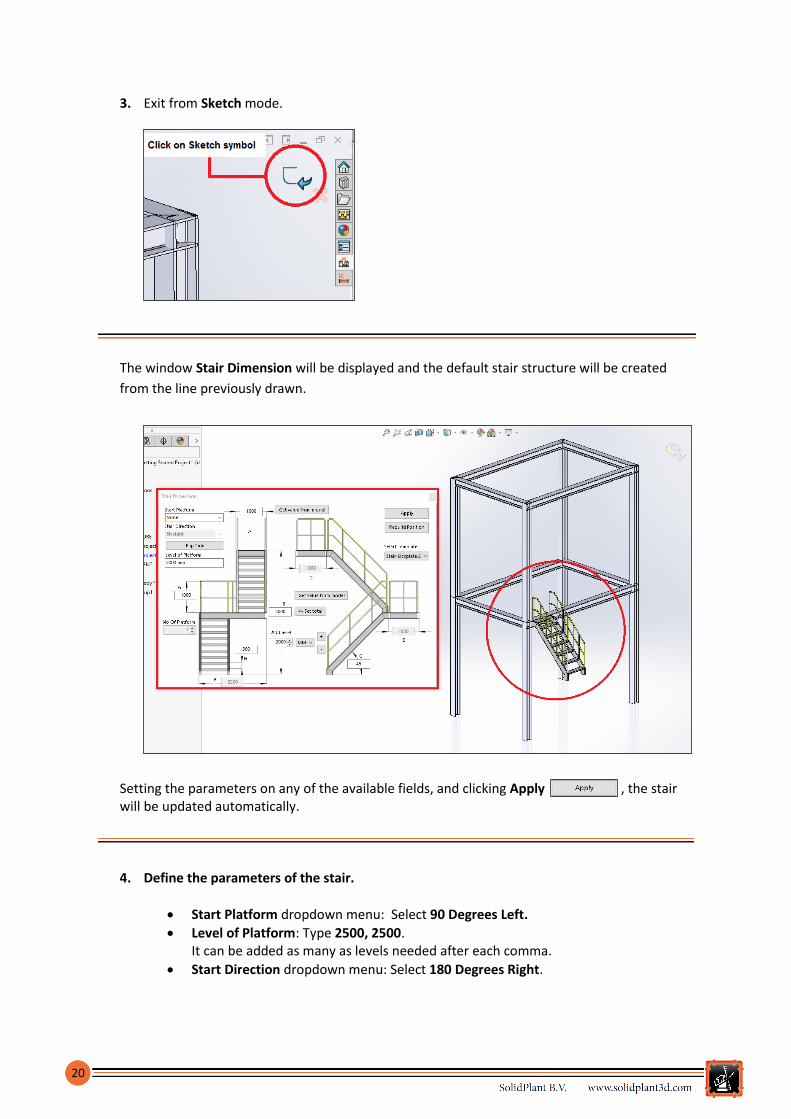
3. Exit from Sketch mode.
The window Stair Dimension will be displayed and the default stair structure will be created
from the line previously drawn.
Setting the parameters on any of the available fields, and clicking Apply , the stair will be updated automatically.
4. Define the parameters of the stair.
Start Platform dropdown menu: Select 90 Degrees Left.
Level of Platform: Type 2500, 2500. It can be added as many as levels needed after each comma.
Start Direction dropdown menu: Select 180 Degrees Right.
21
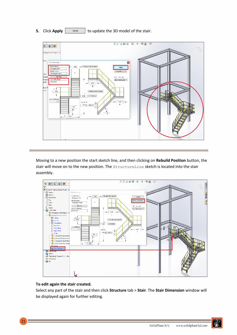
5. Click Apply to update the 3D model of the stair.
Moving to a new position the start sketch line, and then clicking on Rebuild Position button, the
stair will move on to the new position. The StructureLine sketch is located into the stair
assembly.
To edit again the stair created.
Select any part of the stair and then click Structure tab > Stair. The Stair Dimension window will
be displayed again for further editing.
22
Create equipment
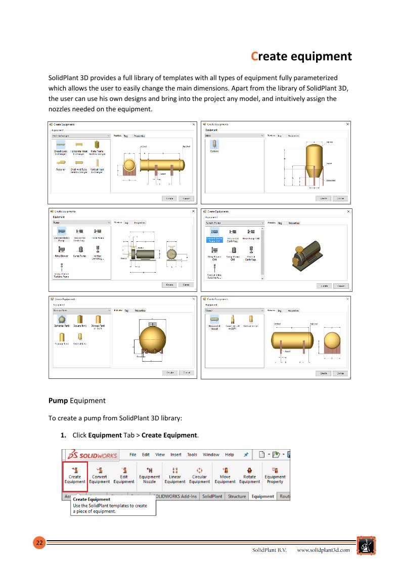
SolidPlant 3D provides a full library of templates with all types of equipment fully parameterized
which allows the user to easily change the main dimensions. Apart from the library of SolidPlant 3D,
the user can use his own designs and bring into the project any model, and intuitively assign the
nozzles needed on the equipment.
Pump Equipment
To create a pump from SolidPlant 3D library:
1. Click Equipment Tab > Create Equipment.
23
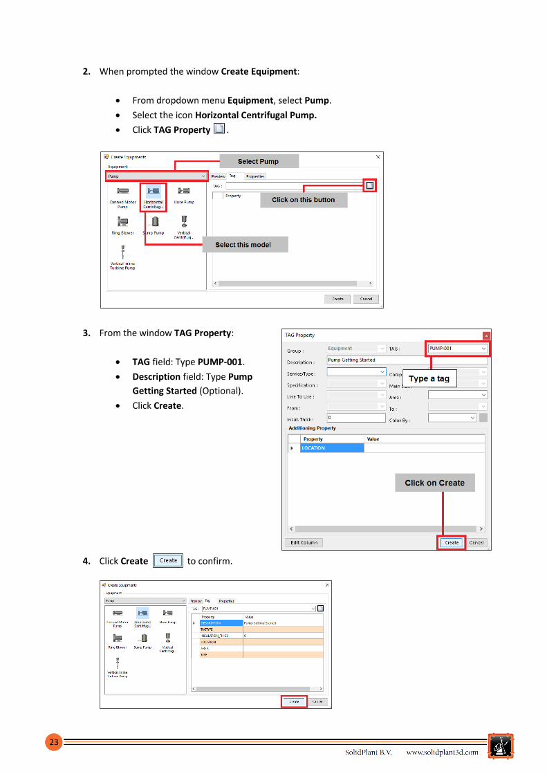
2. When prompted the window Create Equipment:
From dropdown menu Equipment, select Pump.
Select the icon Horizontal Centrifugal Pump.
Click TAG Property .
3. From the window TAG Property:
TAG field: Type PUMP-001.
Description field: Type Pump
Getting Started (Optional).
Click Create.
4. Click Create to confirm.

24
The new assembly model of the pump is opened along with the Horizontal Centrifugal Pump
dialog box to define the dimensions from A to L fields.
5. Set the dimensions of the pump.
Type the values shown on below picture into the dimesions fields on the Horizontal
Centrifugal Pump window.
6. Click Apply to update the model with the dimensions just set.
7. Create a favorite setting.
Type on Favorite field any name and then click Add in order to save the current
parameters of the pump. From the dropdown menu Favorite will list the newly created
setting. Click Delete to suppress the selected favorite.

25
8. Click Close on the Horizontal Centrifugal Pump dialog box.
The Nozzle Component task pane is displayed on the left hand side
in the PropertyManager of SOLIDWORKS in order to set the
parameters of the equipment nozzle.
By default this pump comes with two nozzles, the user can set the
parameters of the existing nozzles by selecting from the Tag
dropdown menu the available tags on the Nozzle Data tab.
If the Nozzle Component task pane is not displayed in the PropertyManager, click Structure tab
> Equipment Nozzle to display it.
To edit again the pump dimensions, click Equipment Tab > Edit Equipment to access the
Horizontal Centrifugal Pump dialog box for further editing.
9. Set the parameters of the nozzle pump PUMP-001-N1.
Select the values on Nozzle Data tab in the Nozzle Component task pane.
Tag dropdown menu: Select PUMP-001-N1.
Database dropdown menu: Select Demo specification.
Size dropdown menu: Select 6 inches.
End Type dropdown menu: Select FL (Flange connection).
Selected Nozzle list: Select NON STANDARD 150LB FLAT FACE NOZZLE.

26
10. Set the parameters of the nozzle pump PUMP-001-N2.
Select the values on Nozzle Data tab in the Nozzle Component task pane.
Tag dropdown menu: Select PUMP-001-N2.
Database dropdown menu: Select Demo specification.
Size dropdown menu: Select 6 inches.
End Type dropdown menu: Select FL (Flange connection).
Selected Nozzle list: Select NON STANDARD 150LB FLAT FACE NOZZLE.
11. Click Ok on the Nozzle Component task pane.
12. Save from the Standard toolbar and close the pump assembly.
Back to the project, on the Document List node tree is displayed the tag PUMP-001.
13. Click Refresh , if the tag is not displayed.

27
14. Drag & drop the pump into the project assembly.
Click on the tag PUMP-001 on the Document List node tree with the scroll/middle mouse
button and hold it pressed, then drag and drop the pump into the project assembly.
15. Place the pump in the middle of the structure using SOLIDWORKS mates. Click Refresh button to update the status of the tag PUMP-001 on the node tree.
16. Save the project on the Standard toolbar.

28
To access the pump again.
Click right mouse button on the tag PUMP-001 on
the Document List node tree and select Open
Component from the shortcut menu in order to
open and edit the pump.
Vessel Equipment
To create a vessel from SolidPlant 3D library:
1. Click Equipment Tab > Create Equipment.
2. When prompted the window Create Equipment:
From dropdown menu Equipment, select Vessel.
Select the icon Horizontal Vessel.
Click TAG Property .
29
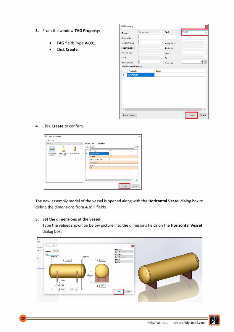
3. From the window TAG Property:
TAG field: Type V-001.
Click Create.
4. Click Create to confirm.
The new assembly model of the vessel is opened along with the Horizontal Vessel dialog box to
define the dimensions from A to F fields.
5. Set the dimensions of the vessel.
Type the values shown on below picture into the dimesions fields on the Horizontal Vessel
dialog box.

30
6. Click Close .
The Nozzle Component task pane is displayed on the left hand side. By default this equipment is
without nozzle.
7. Click New Nozzle and the TAG Property window will be displayed.
8. From the window TAG Property:
Tag dropdown menu: Type V-001-N1.
Database dropdown menu: Select Demo specification.
Size dropdown menu: Select 6 inches.
Click Create.
The Nozzle Component task pane is updated with the new tag and it will
list in the dropdown menu Tag.
9. Set the parameters of the nozzle.
Select the values on the Nozzle Component task pane
that are not yet defined.
End Type dropdown menu: Select FL (Flange
connection).
Selected Nozzle list: Select NON STANDARD
150LB FLAT FACE NOZZLE.
31
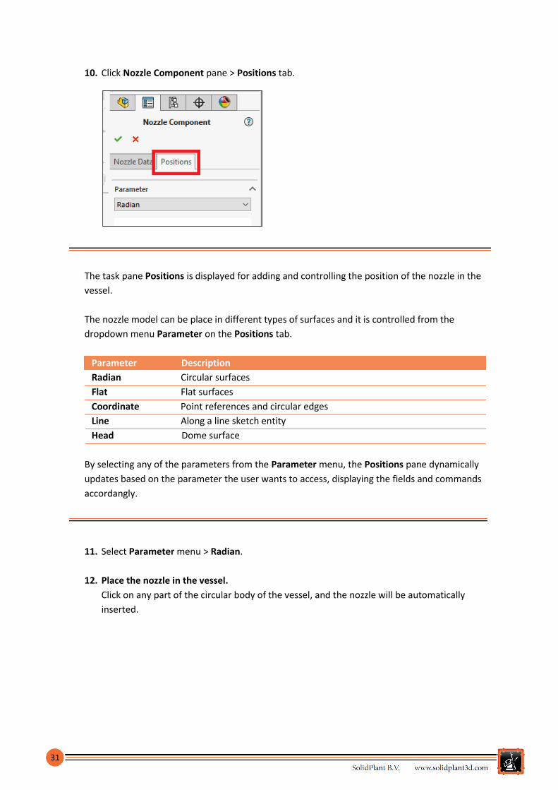
10. Click Nozzle Component pane > Positions tab.
The task pane Positions is displayed for adding and controlling the position of the nozzle in the
vessel.
The nozzle model can be place in different types of surfaces and it is controlled from the
dropdown menu Parameter on the Positions tab.
Parameter Description
Radian Circular surfaces
Flat Flat surfaces
Coordinate Point references and circular edges
Line Along a line sketch entity
Head Dome surface
By selecting any of the parameters from the Parameter menu, the Positions pane dynamically
updates based on the parameter the user wants to access, displaying the fields and commands
accordangly.
11. Select Parameter menu > Radian.
12. Place the nozzle in the vessel.
Click on any part of the circular body of the vessel, and the nozzle will be automatically
inserted.

32
13. On the Dimension area on Position tab, set the parameters:
Angle field: Type 360.
Distance field: Type 4000.
14. Click Apply to update the position of the nozzle.
33
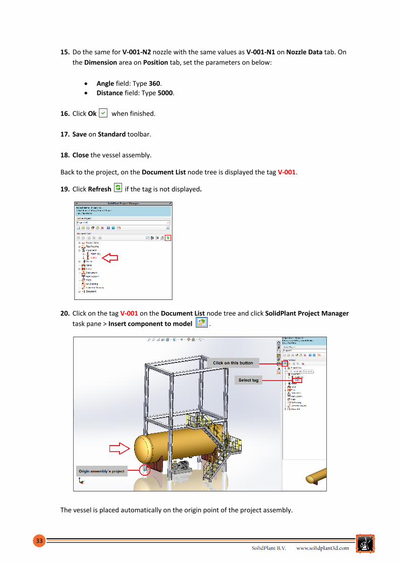
15. Do the same for V-001-N2 nozzle with the same values as V-001-N1 on Nozzle Data tab. On
the Dimension area on Position tab, set the parameters on below:
Angle field: Type 360.
Distance field: Type 5000.
16. Click Ok when finished.
17. Save on Standard toolbar.
18. Close the vessel assembly.
Back to the project, on the Document List node tree is displayed the tag V-001.
19. Click Refresh if the tag is not displayed.
20. Click on the tag V-001 on the Document List node tree and click SolidPlant Project Manager
task pane > Insert component to model .
The vessel is placed automatically on the origin point of the project assembly.

34
21. Place the vessel at the top of the structure using SOLIDWORKS mates.
22. Click Refresh to update the status of the tag V-001 on the node tree.
23. Click Save on Standard toolbar.
Routing
SolidPlant 3D provides the necessary tools to create intelligent pipe routes driven by a piping
specification. Depending on the piping components in the piping specification assigned to the pipe
line in use, the components will be generated automatically from the route that has been created.
The routing features are mainly located in the Routing and Component tabs, and in the side task
pane SolidPlant Pipe Routing.
Creating a pipe line
In SolidPlant the pipe routes are special subassemblies of SOLIDWORKS that build a path of pipes,
tubes or ducts with their piping components based on a 3D sketch of the center line of the route.
When you create a route with SolidPlant 3D, a route subassembly is created into the assembly
project. The tag assigned to the route is the name of the subassembly. Unlike other types of
subassemblies of SOLIDWORKS, you do not create a route assembly in its own window and then
insert it as a component in the higher-level assembly.
SolidPlant uses functionality available in SOLIDWORKS and the user needs to be familiar with 3D
sketching, assemblies, top-down design and mates, in order to become proficient.

35
SolidPlant 3D is a database driven system and the piping specifications assigned to the route will
define the components generated into the pipe subassembly. SolidPlant 3D doesn´t use libraries or
configurations in routing, so that the user doesn´t need to care about preparing the 3D components
before designing. All the information is contained into the piping specification list.
The piping specification list or pipe class is a collection of most compatible components considering
dimensional and material properties for the intended service over a range on pressure and
temperature specified. It is a list for use within its confines and which contains the definition of pipe
and all related components.
SolidPlant 3D comes with SpecCreator that is the application to build up the piping specification list
based on a huge range of catalogues of components. These catalogues contain most of the
standards of the industry (ANSI-ASME, DIN, JIS, etc.) as well as a wide range of manufacturers
(Swagelok, Bonney Forge, George Fisher, etc.). We won´t cover in this document this application so
that the user will use the piping specification Demo that automatically is assigned by default to any
newly created project.
There are three methods to route a line with SolidPlant 3D. In this document we will learn how to
use two of them, Manual Route and Auto Route.
Method Description
Manual Route The user manually sketch the path of the pipe line
Auto Route Automatic generation of the pipe line path based on the selection of
two reference points (e.g. From Nozzle, To Nozzle)
Smart Route Automatic generation of the pipe line based on the information
imported from a P&ID or .xls file into the database of the project
Manual Route method
To create a pipe route:
1. Click Routing Tab > Manual Route.
The Tag property dialog box will display in order to define the parameters of the pipe route.
As the user has already realized, the Tag property dialog box is also used to define the
properties of the equipment and their nozzles.

36
Field Description
Group Displays the type of the component
TAG Unique piping identification
Description Extra information to describe the route
Service/Type Types of fluids. You can select from the dropdown menu or type a value
Specification Dropdown menu listing the piping specifications available in the project
Main Size Dropdown menu listing the sizes available from the selected piping
specification
Line To Use Disabled in pipe routing. It is used to assign a component to a pipe line
Area Dropdown menu listing the areas available in which a pipe line can be
grouped
From Dropdown menu listing all the lines, equipment and equipment nozzle
tags available where the pipe starts
To Dropdown menu listing all the lines, equipment and equipment nozzle
tags available where the pipe ends
Insul. Thick Insulation thickness. You can type a number in millimeters
Color By Dropdown menu listing the different ways to define the color of the pipe
line
Additioning A collection of fields available for adding further information to the pipe
Property line which can be extended by the user
2. From the window TAG Property:
Tag field: Type PIP-001
Specification dropdown menu:
Select Demo.
Description field: Type Getting
Started Pipe 001 (Optional).
Main Size dropdown menu: Select
6 inches.
3. Click Create.

37
On creating the pipe line the user is automatically on 3D Sketch
mode and the tool Line is active. On the FeatureManager
of SOLIDWORKS, the subassembly PIP-001 with the name of the
tag is created and the sketch line of the route will be active, 3DSketch1.
The pipe subassembly contains two folders, Pipe and Component
where it will store the piping components.
Folder Description
Pipe Contains the parts of the pipe sections of the
route
Component Contains the component parts of the route
(Flanges, valves, elbows, etc.)
Once a line is sketched, the 3DSketch1 will be renamed to
Main. If a line is not created, the 3D Sketch won´t be created.
4. Hide the folder Structure for better performance and clearer environment.
5. Sketch a line.
Sketch a line vertically along Z axis from
the reference point of the nozzle pump
PUMP-001-N2. The length is not
important.
A preview of a pipe will display along the line
to highlight the route.
6. Right-click in the graphic area and select
Select from the shortcut menu to confirm
the line.

38
SolidPlant 3D will display the Select Component window listing all the components available in
the piping specification Demo for the current size of the pipe line, which is 6 inches. The user can
select the components according to his needs for the referring pipe.
SolidPlant 3D is an intelligent system and it recognizes the nozzle point connection so that it will
display the Select Component window for the needed components depending on the properties
of the nozzle (Flange, gasket and bolts).
7. Select a pipe component.
When prompted, select the pipe component available from the Demo piping specification
from 6 inches size. Select the component shown on the picture below and click Create.
8. Select a flange component.
When prompted, select the flange component shown on the picture below and click Create.

39
9. Select a gasket component.
When prompted, select the component shown on the picture below and click Create.
10. Select bolts component.
When prompted, select the component shown on the next picture and click on Create
button.
.
Double-click on the selected component in the Select Component window will also
confirm the component instead of clicking Create button.

40
The pipe line will be created with all the piping components added automatically. On the
FeatureManager on the left hand side, the pipe section parts will be contained into the Pipe
folder, and the rest of the piping component parts will be on the Component folder.
The user can mark and enable the check box Disable Routing Mode in the SolidPlant Pipe
Routing task pane, in order to disable the automatic generation of the 3D piping components, so
that the user can easily draw the path without any interferences.
11. Mark the check box Disable Routing Mode on the SolidPlant Pipe Routing pane.

41
12. On the CommandManager, click Sketch tab > Line .
13. Sketch a line.
Sketch a path from the end point of the previous pipe line and draw a path as shown on
picture below. The length is not important.
14. Uncheck SolidPlant Pipe Routing > Piping Reference > Disable Routing Mode.
Now the automatic generation of the piping components is enabled again for generating the rest
of the route.
42
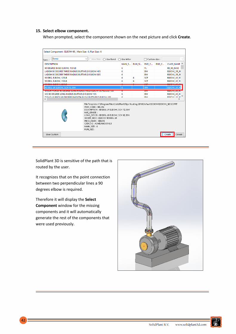
15. Select elbow component.
When prompted, select the component shown on the next picture and click Create.
SolidPlant 3D is sensitive of the path that is
routed by the user.
It recognizes that on the point connection
between two perpendicular lines a 90
degrees elbow is required.
Therefore it will display the Select
Component window for the missing
components and it will automatically
generate the rest of the components that
were used previously.
43
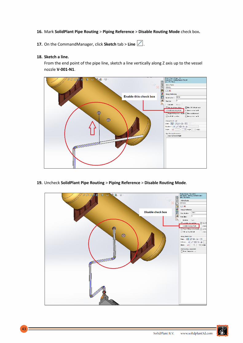
16. Mark SolidPlant Pipe Routing > Piping Reference > Disable Routing Mode check box.
17. On the CommandManager, click Sketch tab > Line .
18. Sketch a line.
From the end point of the pipe line, sketch a line vertically along Z axis up to the vessel
nozzle V-001-N1.
19. Uncheck SolidPlant Pipe Routing > Piping Reference > Disable Routing Mode.

44
SolidPlant 3D will generate all the piping components of the route with the same components
used previously.
If any line of the path is toggled For construction in the PropertyManager, SolidPlant
3D will remove the pipe section as it doesn´t recognize Centerlines as part of the
pipe path. The user will be able to use the Centerline tool for referencing purposes.
20. Exit from 3D Sketch mode.
21. Exit from Edit Assembly mode.
22. Save on Standard toolbar.
Auto Route method
To create a pipe route:
1. Click SolidPlant Pipe Routing Pane > New pipe model
2. From the window TAG Property:
Tag field: Type PIP-002
Specification dropdown menu: Select Demo.
Description field: Getting Started Pipe 001 (Optional).
Size dropdown menu: Select 6 inches.
3. Click Create.
On creating the pipe line the user is automatically on 3D Sketch mode and the tool Line
is active.

45
4. Click Routing Tab > Auto Route.
The task pane Auto Route Line is displayed on the left hand side on the PropertyManager.
5. Select the edge of the pump nozzle PUMP-001-N1.
6. Select the edge of the vessel nozzle V-001-N2.

46
A preview of the path between the two nozzles is displayed. Along the path are available arrows
to alternate the direction of the current route.
7. Click just once Auto Route Line pane > Ok when the path is finished.
8. Mark the check box Disable Routing Mode on the SolidPlant Pip Routing pane.
9. Click Auto Route Line pane > Ok .
The user can change the route by adding or deleting new lines without generating the 3D piping
components.

47
10. Sketch a line.
Sketch the path as shown on below picture to avoid the existing pipe PIP-001, by adding or
deleting the necessary lines.
11. Uncheck SolidPlant Pipe Routing > Piping Reference > Disable Routing Mode.
12. When prompted Select Component windows the user can select the same components as
PIP-001 for Pipe, Flange, Gasket, Bolt and Elbow.

48
13. Exit from 3D Sketch mode.
14. Exit Edit Assembly mode.
15. Save the project.
Adding components
Valve component
1. Make active the route.
Right-click on the sketch line of PIP-002 shown on picture below and select Edit Sketch
from the shortcut menu.
The route will be on 3D Sketch mode ready to be edited.
2. Just click on any point of the
sketch line (recommended
around the middle).
3. Click Component Tab > Valve.

49
4. When prompted, select Selection Point option and click Apply.
A point will be added where the user clicked on previously and it will be the middle reference
point of the valve. The dialog box Valve Property will be displayed in order to define the tag of
the valve.
5. When prompted, type
VALV-001 on the Tag
field.
6. Click Ok.
7. Select valve component.
When prompted, select the component shown on the next picture and click Create.

50
8. Select flange component.
When prompted, select the component shown on the next picture and click Create.
9. Select bolt component.
When prompted, select the component shown on the next picture and click Create.
The valve is added automatically on the sketch line and its reference point is the middle point
which has split the line into two sketch lines.

51
10. Select the sketch line highlighted on the picture below.
11. Click Routing Tab > Assign Length.

52
12. When prompted, type 500 mm on field Change pipe
length to (mm).
13. Click Apply.
The pipe section will change to 500mm length automatically from the selected sketch line. The
user doesn´t need to calculate the dimension value to get the needed length for the section.
14. Exit from 3D Sketch mode.
15. Exit Edit Assembly mode.
16. Save on Standard toolbar.
Pipe Support component
1. Right-click on any sketch line of PIP-002 and from the shortcut menu click Edit Sketch
to make the line active.

53
2. Click Routing Tab > Pipe Support.
The window Available Pipe Support is displayed with the pipe supports available in the library of
SolidPlant 3D.
3. Just click on any point of the sketch line (recommended around the middle).
4. Double-click on the icon Pipe Support B on the Available Pipe Support window.
The pipe support is placed on the selected point on the pipe line. Notice that the support has
been adjusted automatically to the outer diameter of the pipe.
54
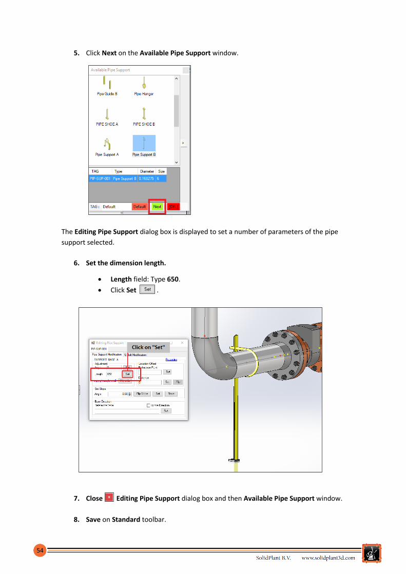
5. Click Next on the Available Pipe Support window.
The Editing Pipe Support dialog box is displayed to set a number of parameters of the pipe
support selected.
6. Set the dimension length.
Length field: Type 650.
Click Set .
7. Close Editing Pipe Support dialog box and then Available Pipe Support window.
8. Save on Standard toolbar.
55
Drawings
SolidPlant 3D has embedded Isogen® from Alias for the total automation of piping isometric drawing
production and is the de facto standard CAD system for drawing piping isometrics. The user will
eliminate the need to manually edit isometric drawings which significantly reduces fabrication and
on-site construction errors.
Also SolidPlant 3D provides the tools needed to create professional GA Drawings, Plane Sections,
etc.
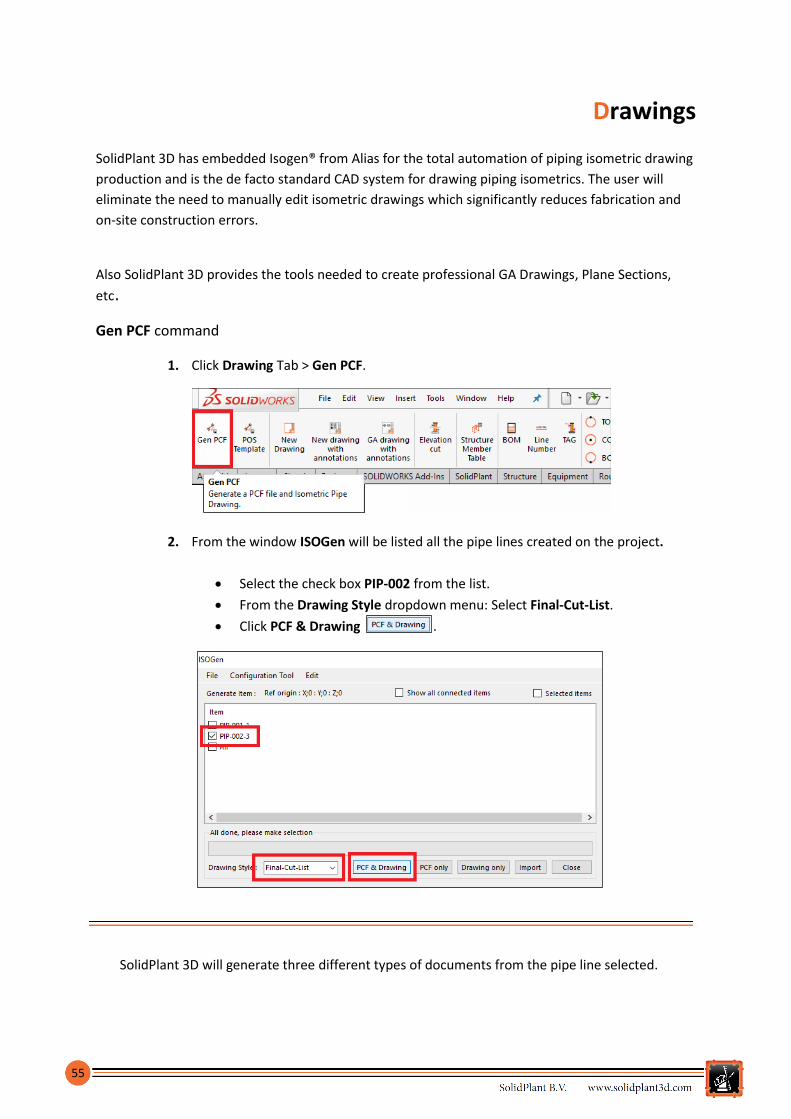
Gen PCF command
1. Click Drawing Tab > Gen PCF.
2. From the window ISOGen will be listed all the pipe lines created on the project.
Select the check box PIP-002 from the list.
From the Drawing Style dropdown menu: Select Final-Cut-List.
Click PCF & Drawing .
SolidPlant 3D will generate three different types of documents from the pipe line selected.

56
Type Description
PCF The Piping Component File is the primary input for personal ISOGEN.
PCFs are text files containing the component and routing information.
DWG/DXF CAD Drawing files.
SLDDRW SOLIDWORKS Drawing Document.
The PCF can be directly imported into pipe stress analysis software like AutoPIPE,
CAESER II or ROHR 2. By default, these documents are located in: C:\ProgramData\SolidPlant Projects\Project 01\Isometric Drawing.
SolidPlant 3D automatically will display the Isometric Drawing in SLDDRW document.
3. Close the SOLIDWORKS drawing of the piping isometric.
These documents will be listed into the Document List node tree on the SolidPlant Project
Manager pane.
4. Click Refresh if not displayed.
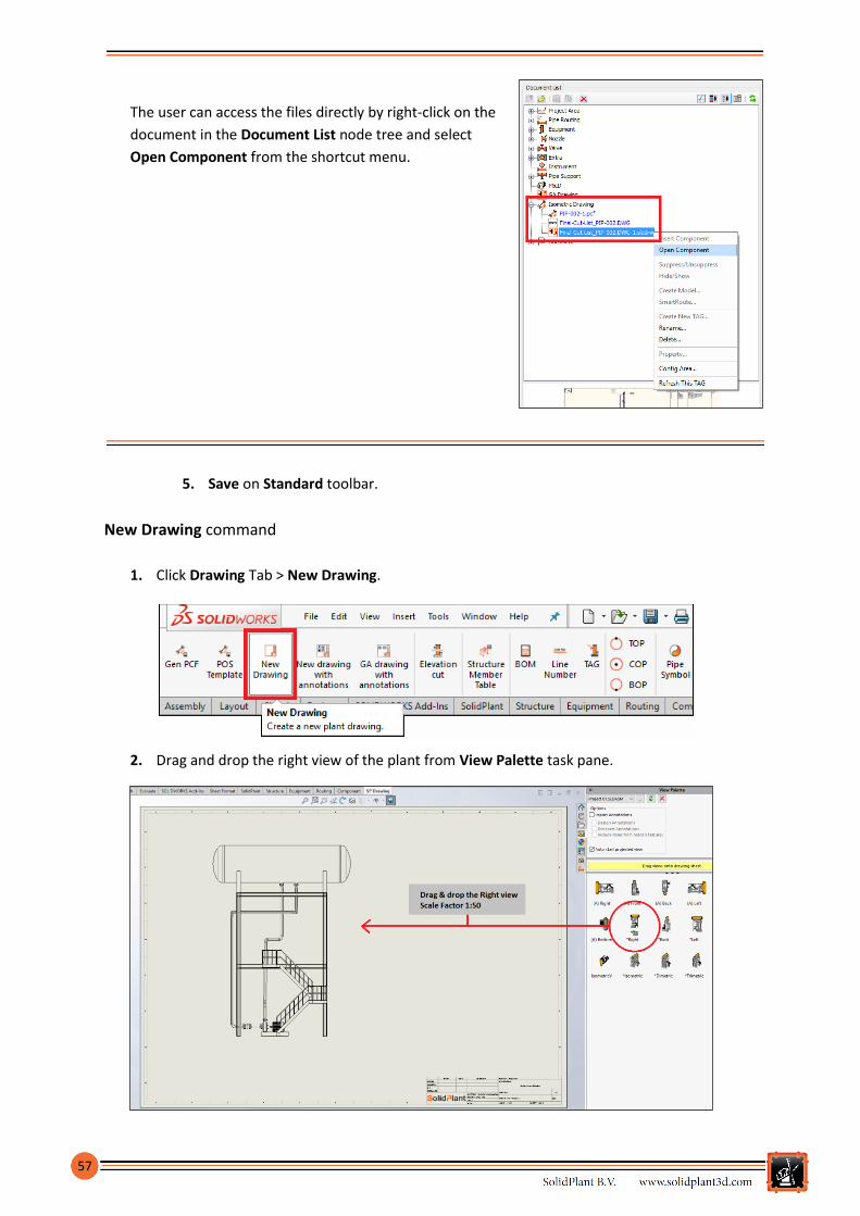
57
The user can access the files directly by right-click on the
document in the Document List node tree and select
Open Component from the shortcut menu.
5. Save on Standard toolbar.
New Drawing command
1. Click Drawing Tab > New Drawing.
2. Drag and drop the right view of the plant from View Palette task pane.

58
3. Click on any pipe section.
4. Click Drawing Tab > Line Number command.
An annotation will be displayed on the pipe section.
5. Click on any pipe section.
6. Click on Drawing Tab > COP .
The dimension annotation will be
displayed between the center of
the pipe and the ground level.
TOP: Top Of Pipe.
COP: Center Of Pipe.
BOP: Bottom Of Pipe.

59
BOM command
1. Select the project view from the
drawing.
2. Click Drawing Tab > BOM.
The bill of materials is displayed.
3. Click To Excel button to export to an .xls file.

60
The bill of materials is exported to an .xls file and it is automatically opened.
4. Close the .xls file.
5. Click Close to place the bill of materials into the drawing.

61
6. Move the bill of materials table wherever you want.
7. Close SOLIDWORKS Drawing.
8. Save on Standard toolbar.
62

63
There are three ways to display the TAG Property window in order to start creating a new pipe
line in SolidPlant 3D.
16. From SolidPlant Pipe Routing Pane > New pipe model… button.