Embed Size (px)
Citation preview
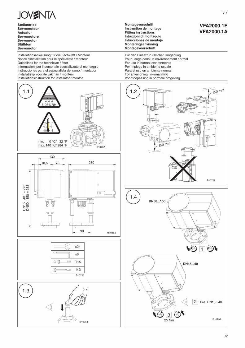
MontagevorschriftInstruction de montageFitting instructionsIntruzioni di montaggioIntrucciones de montajeMonteringsanvisningMontagevoorschrift
./2
1.3
1.21.1
Installationsanweisung für die Fachkraft / MonteurNotice d'installation pour le spécialiste / monteurGuidelines for the technician / fitterInformazioni per il personale specializzato di montaggioInstrucciones para el especialista del ramo / montadorInstallatietip voor de vakman / monteurInstallationsinstruktion för installatör / montör
Für den Einsatz in üblicher UmgebungPour usage dans un environnement normalFor use in normal environmentsPer impiego in ambiente usualePara el uso en ambiente normalFör användning i normal miljöVoor toepassing in normale omgeving
StellantriebServomoteurActuatorServomotoreServomotorStälldonServomotor
VFA2000.1EVFA2000.1A
7.1
5-95%RH
55°C
131°F14-10
min. 0 °C/ 32 °Fmax. 140 °C/ 284 °F
18,5
130
73 230
DN
15...
40
= 2
75D
N50
...15
0 =
283
90
s24
s6
T15
1/ 3
B10753
B10754
B10768
B10767
M10453
2
3
DN15...40
Pos. DN15...40
25 Nm B10792
1
DN50...1501.4
- 2 - 7.1
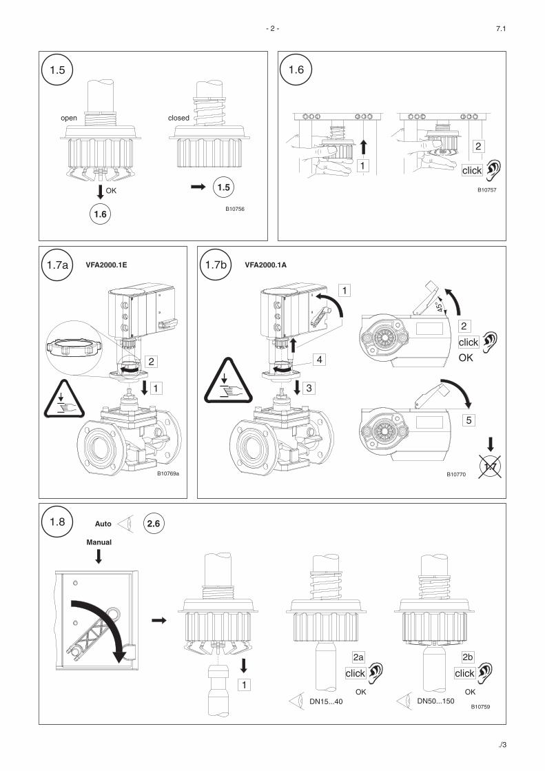
1.5
open
1.6
1.5OK
2
click
closed
1
1.6
1
2
45°
3
4
1
2
click
OK
5
1.7b1.7a
1.7
1.8
OK
click
Manual
Auto
OK
click
DN15...40 DN50...150
1
2a 2b
2.6
./3
VFA2000.1E VFA2000.1A
B10756
B10757
B10769a B10770
B10759
– 3 – 7.1
./4
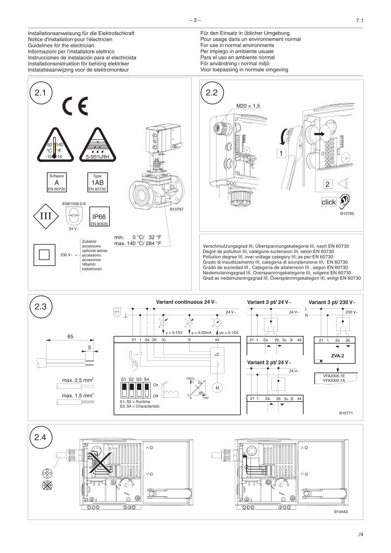
Für den Einsatz in üblicher UmgebungPour usage dans un environnement normalFor use in normal environmentsPer impiego in ambiente usualePara el uso en ambiente normalFör användning i normal miljöVoor toepassing in normale omgeving
Installationsanweisung für die ElektrofachkraftNotice d'installation pour l'électricienGuidelines for the electricianInformazioni per l'installatore elettricoInstrucciones de instalación para el electricistaInstallationsinstruktion för behörig elektrikerInstalatieaanwijzing voor de elektromonteur
EN61558-2-6
24 V~
60°C
140°F14-10 5-95%RH
EN 60529
IP66
230 V~ +
Zubehöraccessoireoptional extrasaccessorioaccesoriostillbehörtoebehoren
AEN 60730
Sofware
1ABEN 60730
Type
Verschmutzungsgrad III, Überspannungskategorie III, nach EN 60730Degré de pollution III, catégorie surtension III, selon EN 60730Pollution degree III, over voltage category III; as per EN 60730Grado di insudiciamento III, categoria di sovratensione III, EN 60730Grado de suciedad III , Categoría de altatensión III , según EN 60730Nedsmutsningsgrad III, Overspanningskategorie III, volgens EN 60730Grad av nedsmutsningsgrad III, Överspänningskategori III, enligt EN 60730
B10443
min. 0 °C/ 32 °Fmax. 140 °C/ 284 °F
2.1
2.4
2.3
2.2
443i2b2a
y = 4-20mA yo = 0-10V
0 10V
2b
2a100%
0
M
�C
3u
y = 0-10V
24 V~
2b2a1
2b2a1
121 21
21
3u 3i 44
3u 3i 44
On
Off
S1 S2 S3 S4
S1; S2 = RuntimeS3; S4 = Characteristic
M20 × 1,5
2
click
1
max. 2,5 mm2
max. 1,5 mm2
65
5
B10767B10760
B10771
Variant 3 pt/ 24 V�Variant continuous 24 V� Variant 3 pt/ 230 V�
24 V~
24 V~
Variant 2 pt/ 24 V�
2b2a1
L
N
21
ZVA.2
VFA2000.1EVFA2000.1A
230 V~
– 4 – 7.1
./5
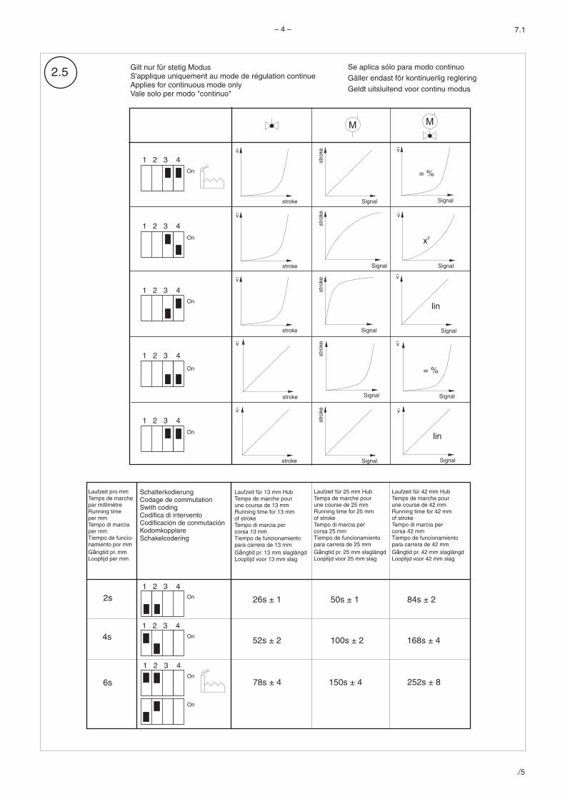
2.5
Laufzeit pro mmTemps de marchepar millimètreRunning timeper mmTempo di marciaper mmTiempo de funcio-namiento por mmG ngtid pr. mmLooptijd per mm
å
SchalterkodierungCodage de commutationSwith codingCodifica di interventoCodificación de conmutaciónKodomkopplareSchakelcodering
Laufzeit für 13 mm HubTemps de marche pourune course de 1 mmRunning time for 1 mmof strokeTempo di marcia percorsa 1 mmTiempo de funcionamientopara carrera de 1 mmG ngtid pr. 1 mm slaglängdLooptijd voor 1 mm slag
33
3
33
3å
2s 26s ± 1 50s ± 1 84s ± 2
4s 52s ± 2 100s ± 2 168s ± 4
6s 78s ± 4 150s ± 4 252s ± 8
On
On
On
1 2 3 4
1 2 3 4
1 2 3 4
On
SignalSignal
stro
ke
stroke
v
Signal
v
Signal
Signal
v
Signal
Signal
v
Signalstroke
v
= %
x2
lin
= %
lin
stroke
v
v
stroke
v
v
stroke
v
Signal Signal
On
On
On
On
1 2 3 4
1 2 3 4
1 2 3 4
1 2 3 4
1 2 3 4
stro
kest
roke
stro
kest
roke
M M
On
Laufzeit für 25 mm HubTemps de marche pourune course de 2 mmRunning time for 2 mmof strokeTempo di marcia percorsa 2 mmTiempo de funcionamientopara carrera de 2 mmG ngtid pr. 2 mm slaglängdLooptijd voor 2 mm slag
55
5
55
5å
Laufzeit für 42 mm HubTemps de marche pourune course de 4 mmRunning time for 4 mmof strokeTempo di marcia percorsa 4 mmTiempo de funcionamientopara carrera de 4 mmG ngtid pr. 4 mm slaglängdLooptijd voor 4 mm slag
22
2
22
2å
Gilt nur für stetig ModusS'applique uniquement au mode de régulation continueApplies for continuous mode onlyVale solo per modo "continuo"
Se aplica sólo para modo continuoGäller endast för kontinuerlig regleringGeldt uitsluitend voor continu modus
– 5 – 7.1
./6
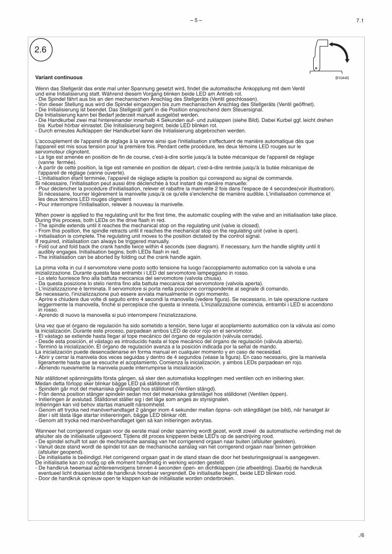
Wenn das Stellgerät das erste mal unter Spannung gesetzt wird, findet die automatische Ankopplung mit dem Ventilund eine Initialisierung statt. Während diesem Vorgang blinken beide LED am Antrieb rot.- Die Spindel fährt aus bis an den mechanischen Anschlag des Stellgeräts ( ).- Von dieser Stellung aus wird die Spindel eingezogen bis zum mechanischen Anschlag des Stellgeräts ( ).- Die Initialisierung ist beendet. Das Stellgerät geht in die Position ensprechend dem Steuersignal.Die Initialisierung kann bei Bedarf jederzeit manuell ausgelöst werden.- Die Handkurbel zwei mal hintereinander innerhalb 4 Sekunden auf- und zuklappen (siehe Bild).
Die Initialisierung beginnt- Durch erneutes Aufklappen der Handkurbel kann die Initialisierung abgebrochen werden.
L'accouplement de l'appareil de réglage à la vanne ainsi que l'initialisation s'effectuent de manière automatique dès quel'appareil est mis sous tension pour la première fois. Pendant cette procédure, les deux témoins LED rouges sur leservomoteur clignotent.- La tige est amenée en position de fin de course, c'est-à-dire sortie jusqu'à la butée mécanique de l'appareil de réglage(vanne fermée).
- A partir de cette position, la tige est ramenée en position de départ, c'est-à-dire rentrée jusqu'à la butée mécanique del'appareil de réglage (vanne ouverte).
- L'initialisation étant terminée, l'appareil de réglage adapte la position qui correspond au signal de commande.Si nécessaire, l'initialisation peut aussi être déclenchée à tout instant de manière manuelle:- Pour déclencher la procédure d'initialisation, relever et rabattre la manivelle 2 fois dans l'espace de 4 secondes(voir illustration).Si nécessaire, tourner légèrement la manivelle jusqu'à ce qu'elle s'enclenche de manière audible. L'initialisation commence etles deux témoins LED rouges clignotent
- Pour interrompre l'initialisation, relever à nouveau la manivelle.
When power is applied to the regulating unit for the first time, the automatic coupling with the valve and an initialisation take place.During this process, both LEDs on the drive flash in red.- The spindle extends until it reaches the mechanical stop on the regulating unit (valve is closed).- From this position, the spindle retracts until it reaches the mechanical stop on the regulating unit (valve is open).- Initialisation is complete. The regulating unit moves to the position dictated by the control signal.If required, initialisation can always be triggered manually.- Fold out and fold back the crank handle twice within 4 seconds (see diagram). If necessary, turn the handle slightly until itaudibly engages. Initialisation begins, both LEDs flash in red.
- The initialisation can be aborted by folding out the crank handle again.
La prima volta in cui il servomotore viene posto sotto tensione ha luogo l'accoppiamento automatico con la valvola e unainizializzazione. Durante questa fase entrambi i LED del servomotore lampeggiano in rosso.- Lo stelo fuoriesce fino alla battuta meccanica del servomotore (valvola chiusa).- Da questa posizione lo stelo rientra fino alla battuta meccanica del servomotore (valvola aperta).- L'inizializzazione è terminata. Il servomotore si porta nella posizione corrispondente al segnale di comando.Se necessario, l'inizializzazione può essere avviata manualmente in ogni momento.- Aprire e chiudere due volte di seguito entro 4 secondi la manovella (vedere figura). Se necessario, in tale operazione ruotareleggermente la manovella, finché si percepisce che questa si innesta. L'inizializzazione comincia, entrambi i LED si accendonoin rosso.
- Aprendo di nuovo la manovella si può interrompere l'inizializzazione.
Una vez que el órgano de regulación ha sido sometido a tensión, tiene lugar el acoplamiento automático con la válvula así comola inicialización. Durante este proceso, parpadean ambos LED de color rojo en el servomotor.- El vástago se extiende hasta llegar al tope mecánico del órgano de regulación (válvula cerrada).- Desde esta posición, el vástago es introducido hasta el tope mecánico del órgano de regulación (válvula abierta).- Terminó la inicialización. El órgano de regulación avanza a la posición indicada por la señal de mando.La inicialización puede desencadenarse en forma manual en cualquier momento y en caso de necesidad.- Abrir y cerrar la manivela dos veces seguidas y dentro de 4 segundos (véase la figura). En caso necesario, gire la manivelaligeramente hasta que se escuche el acoplamiento. Comienza la inicialización, y ambos LEDs parpadean en rojo.
- Abriendo nuevamente la manivela puede interrumpirse la inicialización.
När ställdonet spänningsätts första gången, så sker den automatiska kopplingen med ventilen och en initiering sker.Medan detta förlopp sker blinkar bägge LED på ställdonet rött.- Spindeln går mot det mekaniska gränsläget hos ställdonet (Ventilen ).- Från denna position stänger spindeln sedan mot det mekaniska gränsläget hos ställdonet (Ventilen ).- Initieringen är avslutad. Ställdonet ställer sig i det läge som anges av styrsignalen.Initieringen kan vid behov startas manuellt närsomhelst.- Genom att trycka ned manöverhandtaget 2 gånger inom 4 sekunder mellan öppna- och stängdläget (se bild), när hanatget äråter i sitt låsta läge startar initiereringen, bägge LED blinkar rött.
- Genom att trycka ned manöverhandtaget igen så kan initieringen avbrytas.
Wanneer het corrigerend orgaan voor de eerste maal onder spanning wordt gezet, wordt zowel de automatische verbinding met deafsluiter als de initialisatie uitgevoerd. Tijdens dit proces knipperen beide LED's op de aandrijving rood.- De spindel schuift tot aan de mechanische aanslag van het corrigerend orgaan naar buiten (afsluiter ).- Vanuit deze stand wordt de spindel tot aan de mechanische aanslag van het corrigerend orgaan naar binnen getrokken(afsluiter ).
- De initialisatie is beëindigd. Het corrigerend orgaan gaat in de stand staan die door het besturingssignaal is aangegeven.De initialisatie kan zo nodig op elk moment handmatig in werking worden gesteld.- De handkruk tweemaal achtereenvolgens binnen 4 seconden open- en dichtklappen (zie afbeelding). Daarbij de handkrukeventueel licht draaien totdat de handkruk hoorbaar vergrendelt. De initialisatie begint, beide LED blinken rood.
- Door de handkruk opnieuw open te klappen kan de initialisatie worden onderbroken.
stängdöppen
gesloten
geopend
Ventil geschlossenVentil geöffnet
Dabei Kurbel ggf. leicht drehenbis Kurbel hörbar einrastet. , beide LED blinken rot.
Variant continuous B10445
2.6
– 6 – 7.1
./7
2.7
2.8 2.9
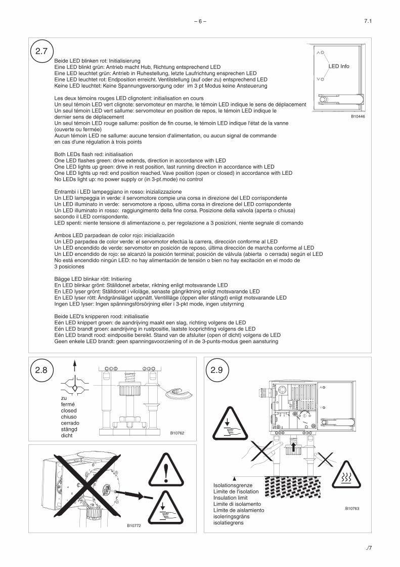
Beide LED blinken rot: InitialisierungEine LED blinkt grün: Antrieb macht Hub, Richtung entsprechend LEDEine LED leuchtet grün: Antrieb in Ruhestellung, letzte Laufrichtung ensprechen LEDEine LED leuchtet rot: Endposition erreicht. Ventilstellung (auf oder zu) entsprechend LEDKeine LED leuchtet: Keine Spannungsversorgung oder im 3 pt Modus keine Ansteuerung
Les deux témoins rouges LED clignotent: initialisation en coursUn seul témoin LED vert clignote: servomoteur en marche, le témoin LED indique le sens de déplacementUn seul témoin LED vert sallume: servomoteur en position de repos, le témoin LED indique ledernier sens de déplacementUn seul témoin LED rouge sallume: position de fin course, le témoin LED indique l'état de la vanne(ouverte ou fermée)Aucun témoin LED ne sallume: aucune tension d'alimentation, ou aucun signal de commandeen cas d'une régulation à trois points
Both LEDs flash red: initialisationOne LED flashes green: drive extends, direction in accordance with LEDOne LED lights up green: drive in rest position, last running direction in accordance with LEDOne LED lights up red: end position reached. Vave position (open or closed) in accordance with LEDNo LEDs light up: no power supply or (in 3-pt.mode) no control
Entrambi i LED lampeggiano in rosso: inizializzazioneUn LED lampeggia in verde: il servomotore compie una corsa in direzione del LED corrispondenteUn LED illuminato in verde: servomotore a riposo, ultima corsa in direzione del LED corrispondenteUn LED illuminato in rosso: raggiungimento della fine corsa. Posizione della valvola (aperta o chiusa)secondo il LED corrispondente.LED spenti: niente tensione di alimentazione o, per regolazione a 3 posizioni, niente segnale di comando
Ambos LED parpadean de color rojo: inicializaciónUn LED parpadea de color verde: el servomotor efectúa la carrera, dirección conforme al LEDUn LED encendido de verde: servomotor en posición de reposo, última dirección de marcha conforme al LEDUn LED encendido de rojo: se alcanzó la posición terminal; posición de válvula (abierta o cerrada) según el LEDNo está encendido ningún LED: no hay alimentación de tensión o bien no hay excitación en el modo de3 posiciones
Bägge LED blinkar rött: InitieringEn LED blinkar grönt: Ställdonet arbetar, riktning enligt motsvarande LEDEn LED lyser grönt: Ställdonet i viloläge, senaste gångriktning enligt motsvarande LEDEn LED lyser rött: Ändgränsläget uppnått. Ventillläge (öppen eller stängd) enligt motsvarande LEDIngen LED lyser: Ingen spänningsförsörjning eller i 3-pkt mode, ingen utstyrning
Beide LED's knipperen rood: initialisatieEén LED knippert groen: de aandrijving maakt een slag, richting volgens de LEDEén LED brandt groen: aandrijving in rustpositie, laatste looprichting volgens de LEDEén LED brandt rood: eindpositie bereikt. Stand van de afsluiter (open of dicht) volgens de LEDGeen enkele LED brandt: geen spanningsvoorziening of in de 3-punts-modus geen aansturing
LED Info
B10446
zuferméclosedchiusocerradostängddicht
IsolationsgrenzeLimite de l'isolationInsulation limitLimite di isolamentoLímite de aislamientoisoleringsgränsisolatiegrens
B10762
B10763
B10772
Dokument aufbewahren/Ce document est à conserver/Retain this document/Conservare il documento/Guardar el documento/Spara dokumenationen/Document bewaren
– 7 –
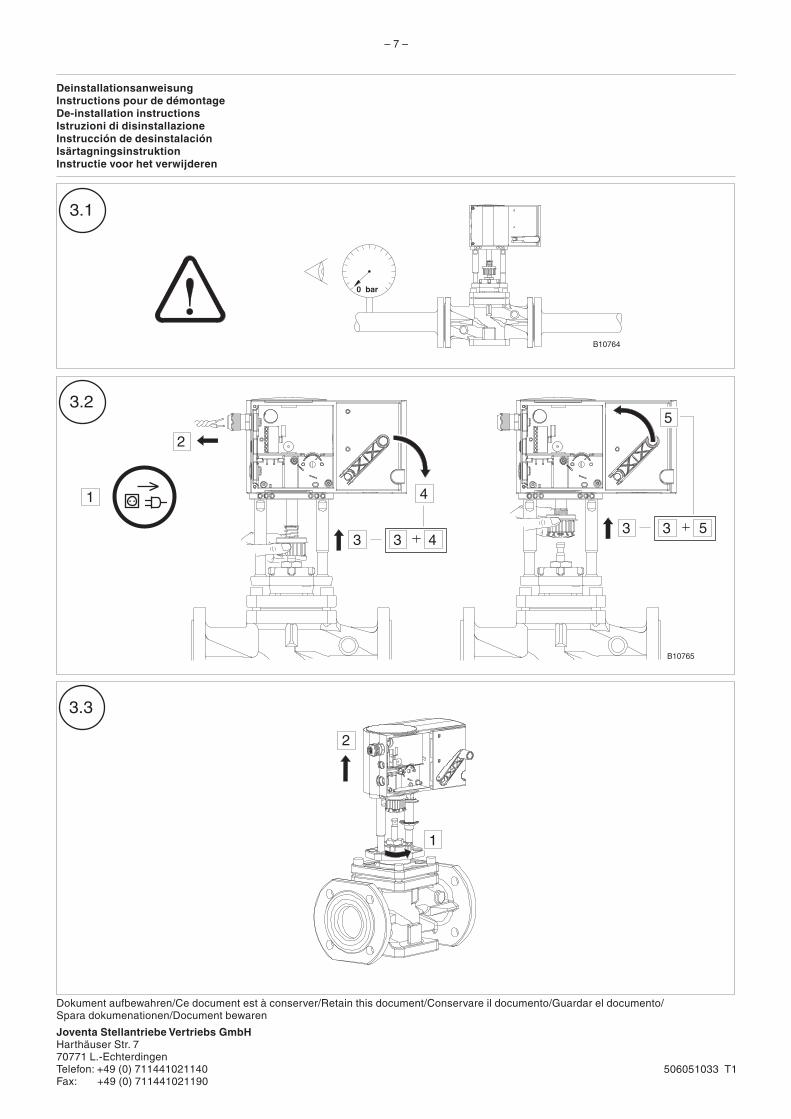
DeinstallationsanweisungInstructions pour de démontageDe-installation instructionsIstruzioni di disinstallazioneInstrucción de desinstalaciónIsärtagningsinstruktionInstructie voor het verwijderen
0 bar
1
3.1
3.2
3.3
3
4
2
3 43 3 5
5
1
2
506051033 T1
B10765
B10764
Joventa Stellantriebe Vertriebs GmbHHarthäuser Str. 770771 L.-EchterdingenTelefon: +49 (0) 711441021140Fax: +49 (0) 711441021190