Embed Size (px)
Citation preview
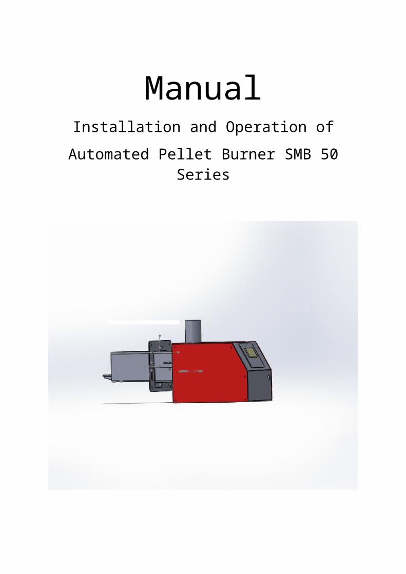
ManualInstallation and Operation of
Automated Pellet Burner SMB 50 Series
Important instructions, keep for future use!!!
Mareli ه Systems Company expresses its gratitude to customers who have purchased our products.
This manual is provided by Mareli Systems Company to assist the team who هwill install, set up, and service this equipment, as well as the customer who will operate it.
Mareli Systems Company requires that the technicians who will perform the هabove procedures shall have passed a training course in the operations related to this product.
CAUTION! For your safety it is necessary to read carefully in details this manual along with the operation and installation manual of automated pellet burner before you start any actions on its installation, set-up, and operation. The same applies to the pellet hopper installation and operation manual, in case the equipment has one. Non-compliance with instructions and violating applicable norms and directives may lead to damages and unforeseen consequences, for which Mareli Plast Company shall not be held liable.
DO NOT DISPOSE OF IN CONTAINERS FOR HOUSEHOLD WASTE!
This mark on the pellet burner means that it must be disposed of only in designated places for waste collection and recycling. The disposal of this appliance falls under the regulation of the European Directive on waste electrical and electronic equipment (WEEE). Dear customers, let us contribute together to the preservation of the environment.
This appliance is not intended for use by physically, sensory or
mentally disabled people or people with insufficient knowledge and
experience (including children). Installation must be performed by a
qualified specialist in the field of heating installations or by an
authorized by Mareli company repair shop. The location and the
connection method of the burner should be carefully chosen by following
the safety instructions. Install away from flammable items!
Never try to make any changes on the burner! The use of flammable
liquids for inflaming is prohibited! Maintenance of the burner must be
carried out by an adult who is familiar with the operation conditions.
Bringing of highly flammable and vaporisable liquids in the room with
working burner is strictly prohibited. Children must not be left
unattended in the room of the combustion system.
Safety distances:
When installing the burner safety distances from a minimum of
200 mm must be observed, if there is no stone wool for wall and
cladding insulation applied. This distance applies to the fireplaces
and flues located in the vicinity of materials of B and C
flammability class. The safety distance shall be doubled if the
camera is located in the vicinity of materials of СЗ flammability
class.
1. Description and Advantages of Automated Pellet Burner SMB 50 Series.
Pellet burners of these series designed for the utilization of wood pellets represent welded steel structure. The resulting heat is being absorbed by the heat exchange surface of the boiler body and is then transmitted to the coolant in the heating system. These burners are used for heating in local heating systems and also for water heating for domestic needs.
The automated pellet burner can utilize the following types of fuel:
Wooden pellets 6 and 8 mm in size, class A;
The automated pellet burner is a compact module structure consisting of the following components:
Burning chamber, which provides conditions for optimal burning process and is manufactured of high quality alloyed steel.
Automated mechanical cleaning.
Burning chamber grate, easy to dismount, allowing removal of ash residue.
Electric heater to kindle the fuel.
Fan supplying air for combustion.
Photo sensor to monitor the combustion process.
An automated pellet burner equipped with a control panel;
Control unit that monitors and controls burner operation and led indication for the operating mode;
Fuel screw conveyor connector feeding the screw conveyor itself;
Interface panel equipped with light indicators;
Transparent panel which visualizes the work of the controller and its mode;
Facility Advantages
It is designed to utilize biomass, which makes it environmentally friendly;
The price of the heat energy generated by the biomass utilization as local energy source is affected to a small extent by the global fuel prices and thus the value of the generated heat energy is competitive to that generated from the use of conventional heat sources;
The facility is automated and provides comfort during operation;
Automatic operation enables adjustment of the work with room thermostat (weekly programmer), which ensures maximum thermal comfort and fuel economy;
Opportunity for energy utilization of biomass in the form of pellets;
High efficiency;
Low level of harmful emissions;
Compact design enabling simple installation and easy maintenance for cleaning and servicing;
Minimum operating costs;
Basic information for the automated pellet burner:
The automated pellet burner shall be mounted horizontally secured by M8 screws.
The pellet burner is a standalone module, which can be mounted to a range of already installed boilers and thus currently used fuel with the so-called densified bio-fuel such as wood pellets can be replaced.
The pellet burner is equipped with a control panel.
Wood pellets enable the easy automation of the process of combustion and highly effective utilization of their energy. During utilization of wood pellets, as well as any other solid fuel, ash residue remains, but its quantity is less in comparison to that remaining during wood or coal utilization due to the pellet composition. And the price of the heat energy from the wood pellets is competitive compared to that generated from other energy carriers. The operation of automated pellet burner corresponds to the functionality of any automatic fossil fuel burner (i.e. gas, diesel, fuel oil): it switches on automatically, fuel ignition is automatic, maintenance of efficient fuel process is precisely controlled by the built-in control module. These are features which enable comfort operation by the already popular automated facilities utilizing fossil fuels, and at the same time the bio-fuel is a product of biomass - eco-friendly and at attractive price.
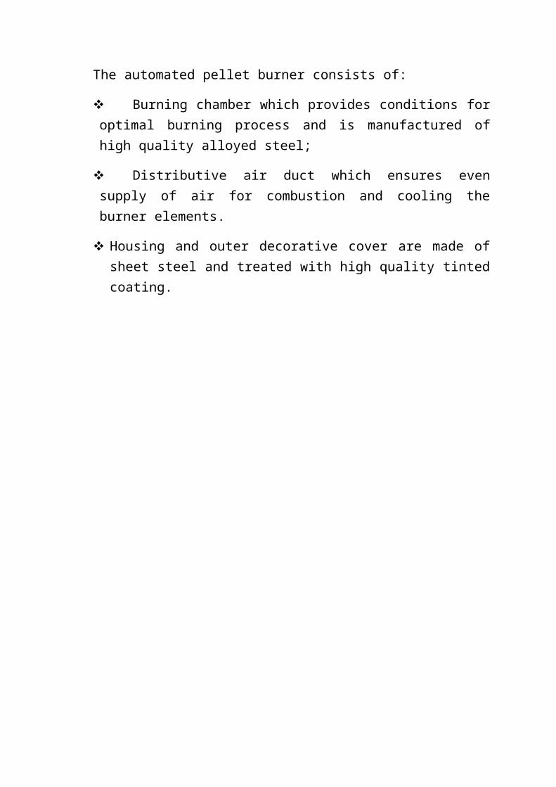
The automated pellet burner consists of:
Burning chamber which provides conditions for optimal burning process and is manufactured of high quality alloyed steel;
Distributive air duct which ensures even supply of air for combustion and cooling the burner elements.
Housing and outer decorative cover are made of sheet steel and treated with high quality tinted coating.
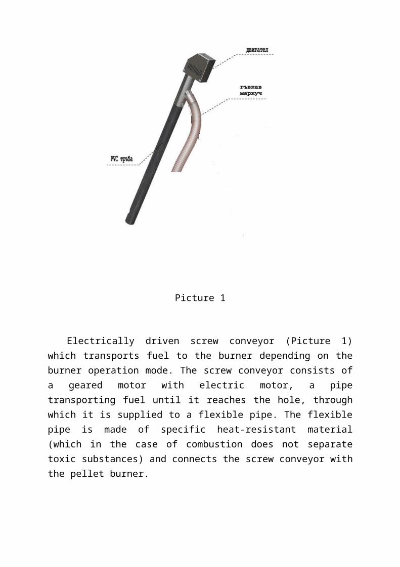
Picture 1
Electrically driven screw conveyor (Picture 1) which transports fuel to the burner depending on the burner operation mode. The screw conveyor consists of a geared motor with electric motor, a pipe transporting fuel until it reaches the hole, through which it is supplied to a flexible pipe. The flexible pipe is made of specific heat-resistant material (which in the case of combustion does not separate toxic substances) and connects the screw conveyor with the pellet burner.
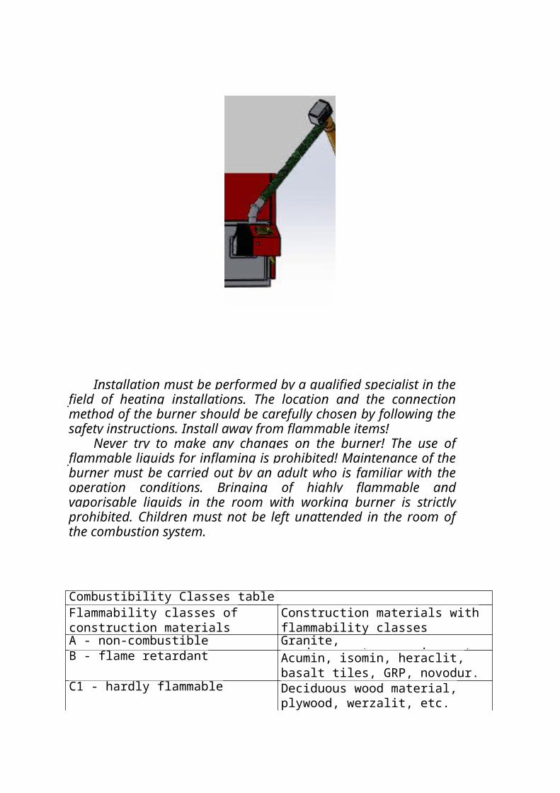
Installation must be performed by a qualified specialist in the field of heating installations. The location and the connection method of the burner should be carefully chosen by following the safety instructions. Install away from flammable items!
Never try to make any changes on the burner! The use of flammable liquids for inflaming is prohibited! Maintenance of the burner must be carried out by an adult who is familiar with the operation conditions. Bringing of highly flammable and vaporisable liquids in the room with working burner is strictly prohibited. Children must not be left unattended in the room of the combustion system.
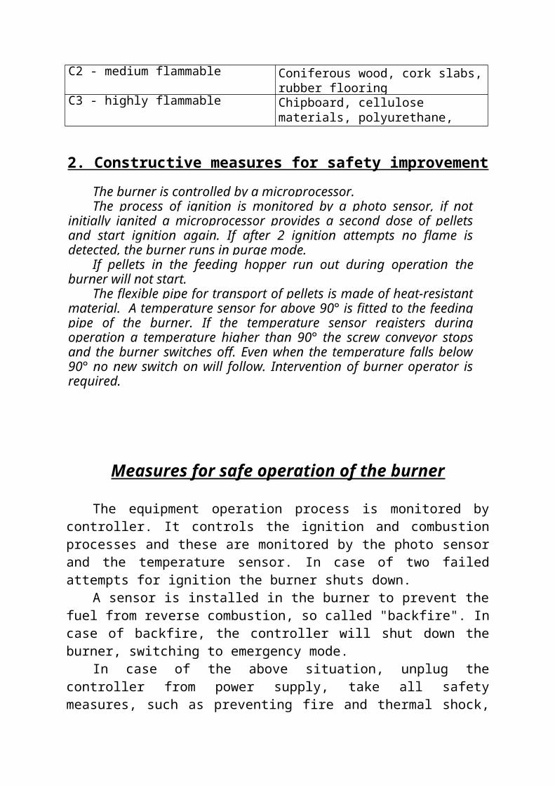
Combustibility Classes tableFlammability classes of construction materials
Construction materials with flammability classes
A - non-combustible Granite, sand,concrete,ceramics, etc.B - flame retardant Acumin, isomin, heraclit, basalt tiles,
GRP, novodur.C1 - hardly flammable Deciduous wood material, plywood,
werzalit, etc.C2 - medium flammable Coniferous wood, cork slabs, rubber
flooringC3 - highly flammable Chipboard, cellulose materials,
polyurethane, polystyrene, etc.
2. Constructive measures for safety improvement
The burner is controlled by a microprocessor.The process of ignition is monitored by a photo sensor, if not
initially ignited a microprocessor provides a second dose of pellets and start ignition again. If after 2 ignition attempts no flame is detected, the burner runs in purge mode.
If pellets in the feeding hopper run out during operation the burner will not start.
The flexible pipe for transport of pellets is made of heat-resistant material. A temperature sensor for above 90° is fitted to the feeding pipe of the burner. If the temperature sensor registers during operation a temperature higher than 90° the screw conveyor stops and the burner switches off. Even when the temperature falls below 90° no new switch on will follow. Intervention of burner operator is required.
Measures for safe operation of the burner
The equipment operation process is monitored by controller. It controls the ignition and combustion processes and these are monitored by the photo sensor and the temperature sensor. In case of two failed attempts for ignition the burner shuts down.
A sensor is installed in the burner to prevent the fuel from reverse combustion, so called "backfire". In case of backfire, the controller will shut down the burner, switching to emergency mode.
In case of the above situation, unplug the controller from power supply, take all safety measures, such as preventing fire and thermal shock, then carefully clean the burner. It is advisable to call an authorized service technician to establish whether the equipment is safe. There is a risk of sensor damage and melting the flexible pellet feeding tube. To prevent backfire, the burner should be checked if it is cleaned, if the settings are proper, and if the burner installation requirements are met.
If during operation the connector is removed or not well adjusted, the burner shuts down automatically.
3. Instructions for connection (installation) to a boiler:
The pellet burner can be attached to a steel or cast iron hot water boiler with a power from 15 to 50 kW. The minimum depth of the combustion chamber should be 450 mm. The automated pellet burner has no secondary air supply.
The distance between the flame and the cooling surface of the boiler must be at least 150 mm.
The facility is deployed so that there will be enough space for cleaning, removing ash from the burner, the boiler and the exhaust pipe.
No items must be placed thereon, leaning or propping against is prohibited, in order not to break the seal. There is a risk of breakage and breach of the burner integrity, as well as to distort its horizontal position, as a result of which - its proper work.
The installation hole of the pellet burner must be 128 mm wide, and 121 mm high. The size of the door which to be joined to must enable incision of the installation hole mentioned above (if there is no such).
The burner is placed in the boiler door hole designated for it with the appropriate seal. It shall be attached securely with M8 screws.
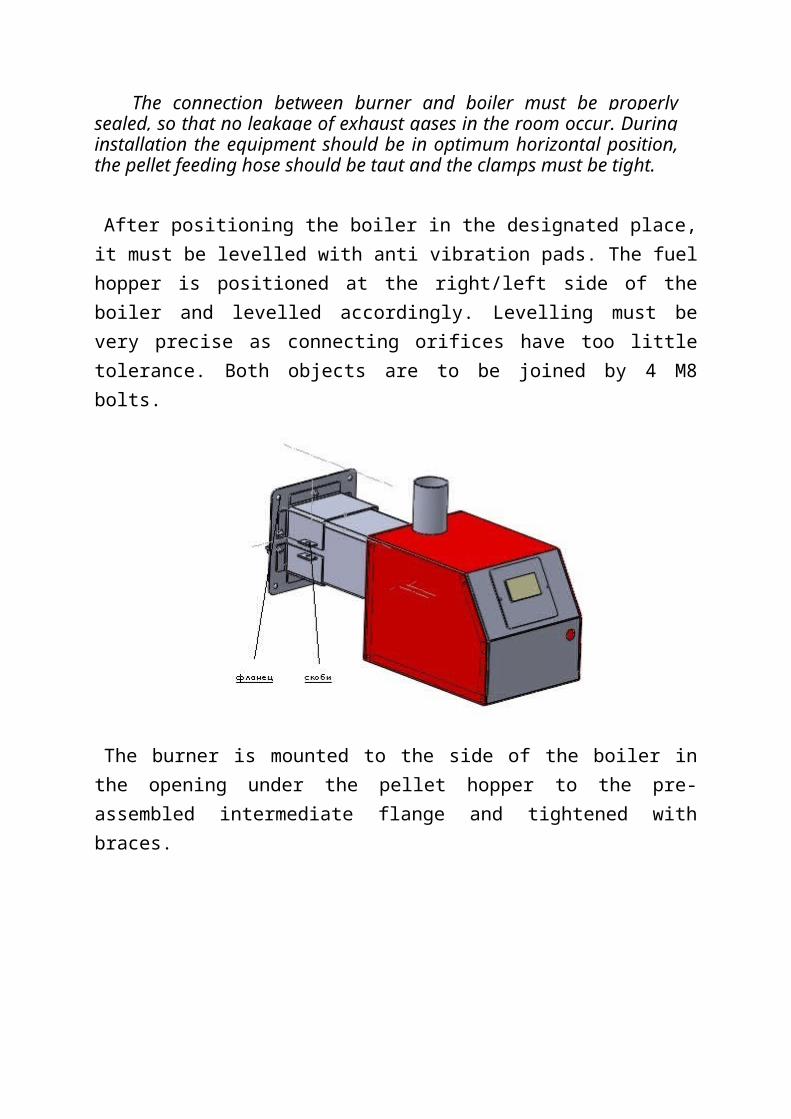
The connection between burner and boiler must be properly sealed, so that no leakage of exhaust gases in the room occur. During installation the equipment should be in optimum horizontal position, the pellet feeding hose should be taut and the clamps must be tight.
After positioning the boiler in the designated place, it must be levelled with anti vibration pads. The fuel hopper is positioned at the right/left side of the boiler and levelled accordingly. Levelling must be very precise as connecting orifices have too little tolerance. Both objects are to be joined by 4 М8 bolts.
The burner is mounted to the side of the boiler in the opening under the pellet hopper to the pre-assembled intermediate flange and tightened with braces.
Appendix 1
- Reconstruction of hot water boiler with automated burner
1. Cut a hole in the available door (if there is no such planned). The sizes described in the instructions should be observed.
2. Thoroughly clean the interior walls of the boiler from ash residue, soot, etc., which would have led to appearance of thermal resistance during facility operation. After cleaning, the drawer for collection of the ash from the combustion chamber must also be taken out.
3. Then, mount and securely attach a pellet burner to the door through M8 screws (which are screwed, where the thread is made on the door itself), which holds the burner to the door.
Explanation:: It must be checked whether sealing ropes ofthe doors fit snugly to the boiler housing. If any gaps are found, the corresponding sealing rope must be replaced and ensure the density of this zone;
4. Install the fuel supply conveyor, which feeds the automated pellet burner.
The fuel supply conveyor must be installed in such a way so that fuel can be freely extracted from the hopper – from its lowest point. In the event that the hopper is made/assembled on site, it is recommended to make a manhole for servicing the rowing area of the screw conveyor. The screw conveyor pipe itself also must be fastened, so as to ensure against upheaval and possible change of the screw conveyor axis angle against the horizontal plane.
Explanation: The tilt angle (between the screw conveyor axis and the horizontal plane) of the screw conveyor has a direct effect on its performance, i.e. the fuel flow which it will provide at a specified operating mode. That is why adjustment of the burner settings is likely to be required upon change of this angle, in order to insure specific heating power.
5. Provide the power supply directly through a plug. Before connecting to the power the burner must be earthed through a 4 mm2 copper wire with yellow-green insulation.
Power supply is provided through a Schuko type plug directly in the mains.
CAUTION! The burner control unit should be plugged in an outlet, which must be earthed. There
is a risk of electric shock in the absence of earthed plug! The manufacturer bears no responsibility!
Pellets are stored in a hopper. The purchased from Mareli Company hopper has a 45-degree tilt. The screw conveyor pipe must be placed therein.
The screw conveyor draws pellets from the hopper and feeds the burner through a flexible connection. Dosing is controlled by the control unit by changing the operating time of the screw conveyor. The initial loading of the screw conveyor with pellets (filling the screw conveyor pipe) is carried out when the screw conveyor plug is connected to a normal 230V/50Hz outlet. As pellets start to fall through the flexible connection, the plug is shifted to the burner.
Important: For ensuring normal operation of the burner a 20 Pa chimney draught is required. After starting the burner, wait for about 3 hours for the chimney to be warmed up and measure the draught. Install additional chimney fan (controlled by the control unit of the burner) if necessary.
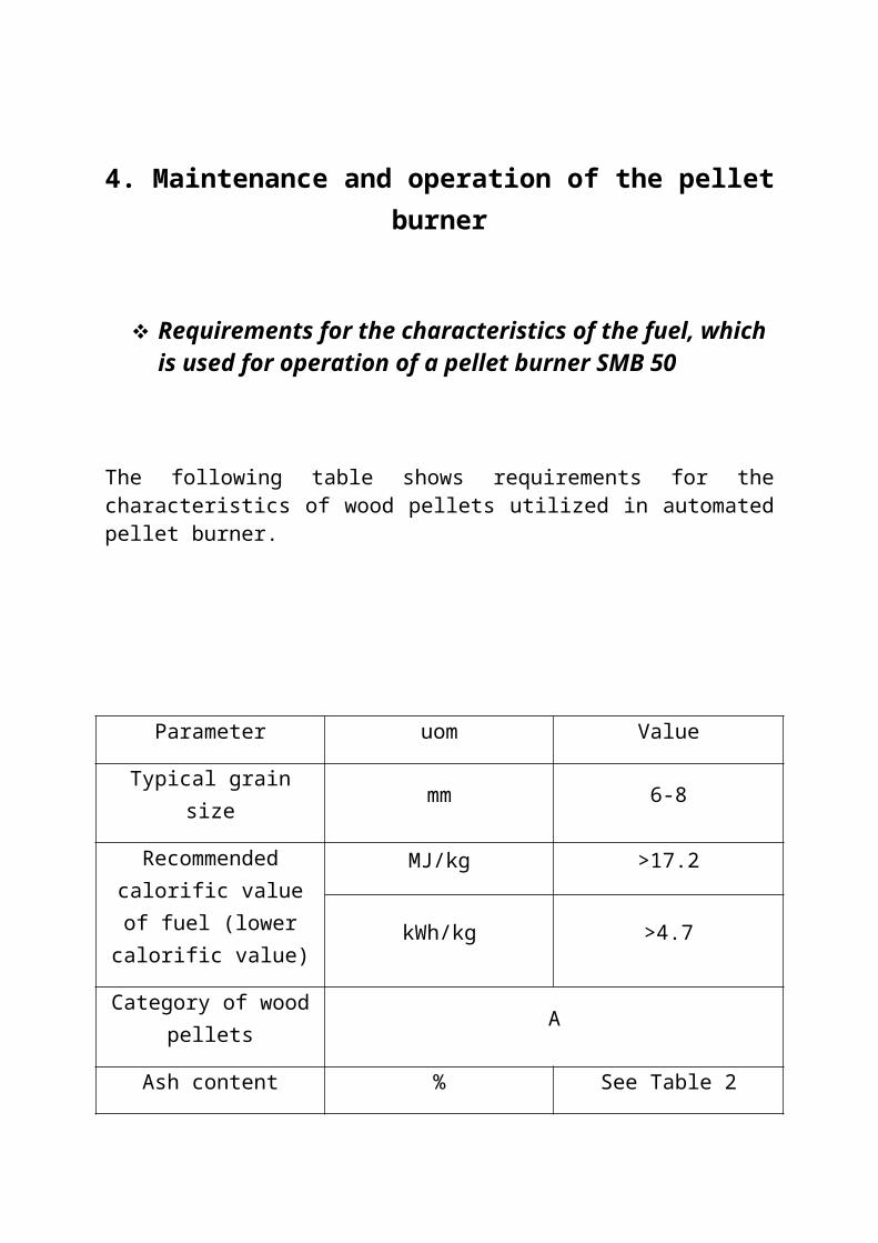
4. Maintenance and operation of the pellet burner
Requirements for the characteristics of the fuel, which is used for operation of a pellet burner SMВ 50
The following table shows requirements for the characteristics of wood pellets utilized in automated pellet burner.
Parameter uom Value
Typical grain size mm 6-8
Recommended calorific value of fuel (lower
calorific value)
МJ/kg >17.2
kWh/kg >4.7
Category of wood pellets А
Ash content % See Table 2
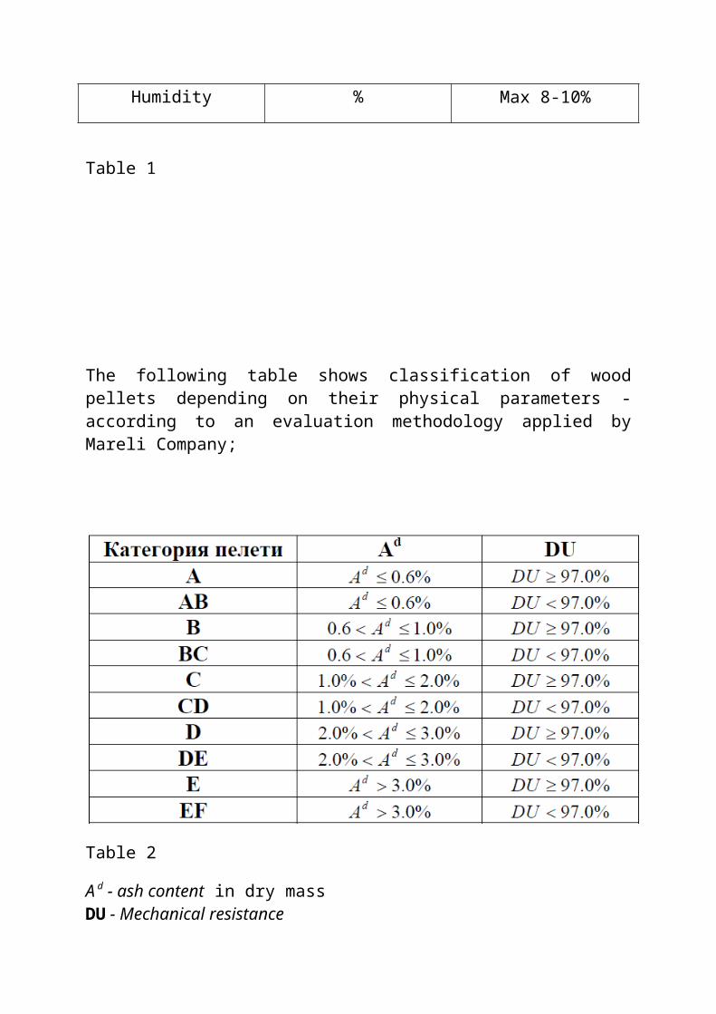
Humidity % Max 8-10%
Table 1
The following table shows classification of wood pellets depending on their physical parameters - according to an evaluation methodology applied by Mareli Company;
Table 2
A d - ash content in dry massDU - Mechanical resistance
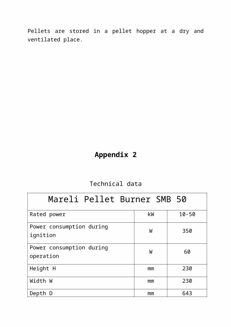
Pellets are stored in a pellet hopper at a dry and ventilated place.
Appendix 2
Technical data
Mareli Pellet Burner SMB 50Rated power kW 10-50
Power consumption during ignition W 350
Power consumption during operation W 60
Height H mm 230
Width W mm 230
Depth D mm 643
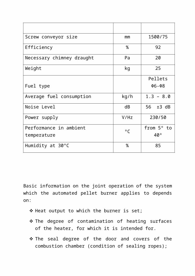
Screw conveyor size mm 1500/75
Efficiency % 92
Necessary chimney draught Pa 20
Weight kg 25
Fuel type Pellets Φ6-Φ8
Average fuel consumption kg/h 1.3 – 8.0
Noise Level dB 56 ±3 dB
Power supply V/Hz 230/50
Performance in ambient temperature ºC from 5º to 40º
Humidity at 30°C % 85
Basic information on the joint operation of the system which the automated pellet burner applies to depends on:
Heat output to which the burner is set;
The degree of contamination of heating surfaces of the heater, for which it is intended for.
The seal degree of the door and covers of the combustion chamber (condition of sealing ropes);
Chimney draught;
Good chimney draught is essential for proper functioning of the heating system. Boiler capacity and economical operation depend largely on it. The heater can only be connected to a chimney with a good draught.
Attention!
Suffocation hazard due to lack of oxygen in the installation room.
Ensure sufficient fresh air supply through holes out.
Risk of injury/damage to equipment due to lack of combustion air can lead to tar and noxious gas formation.
Ensure sufficient fresh air supply through holes out.
Notify the user of the installation that these holes must remain open.
NOTES: When using the circulation pump for the transmission of heat energy from
the hot water boiler to the heating system it is not recommended that the return („cold“) water's temperature is lower than 60oC, since a local (in the heat exchanger of the boiler) overcooling of flue gases and condensing water vapour, which is one of the end products of fuel combustion, is possible.
Continued operation of the burner is not recommended when the heat rating is less than 50% of the nominal, since such operating modes are not efficient and not cost effective, unless the combustion process is not set up exactly in such operating mode.
EXPLANATION: If the boiler has to operate in a heat power mode which is lower than 50% of the nominal, it is recommended that a heat accumulator is installed to the heating system which to ensure a reliable, economical, and efficient operation of the boiler-burner system in the installation.
Why is regular maintenance important
Heating systems should be maintained on a regular basis for the following reasons:
To maintain high efficiency and to operate the heating system economically (with low fuel consumption);
Achieving high safety of operation;
Achieving high environment-friendly combustion;
5. Pellet burner cleaning
The appliance must be cleaned regularly for long and good operation of the pellet burner . Cleaning is done when the burner is stopped and switched off from the mains. The more qualitative the pellets used are, the longer the intervals between cleaning will be.
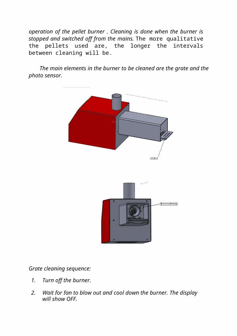
The main elements in the burner to be cleaned are the grate and the photo sensor.
Grate cleaning sequence:
1. Turn off the burner.
2. Wait for fan to blow out and cool down the burner. The display will show OFF.
3. Switch to OFF the power supply button.
4. Open the boiler door.
5. Using gloves or pliers (temperature is still high), remove the grate and clean it.
6. Place the grate back into the burner.
7. Make sure the basin stops are at position. Improper installation will result in auto-shut off of the burner thereafter.
8. Switch to ON the power supply button.
9. Start the burner.
Clean the photo sensor once per every 2 months or more often if necessary. Simply open the top cover of the burner by unscrewing the fixing screws. The photo sensor is located in the upper left corner. Remove the fixing screw and clean with a dry soft cloth. Check the fan, and clean it if necessary.
Do not use any cleaning agents.
Boiler... Clean the ashes from the boiler with a brush and remove the soot.
Pellet hopper... Clean the pellet hopper periodically. When using lower quality pellets, they generate ash, which accumulates on the hopper base and impedes the passage of the pellets.
Additional instructions:
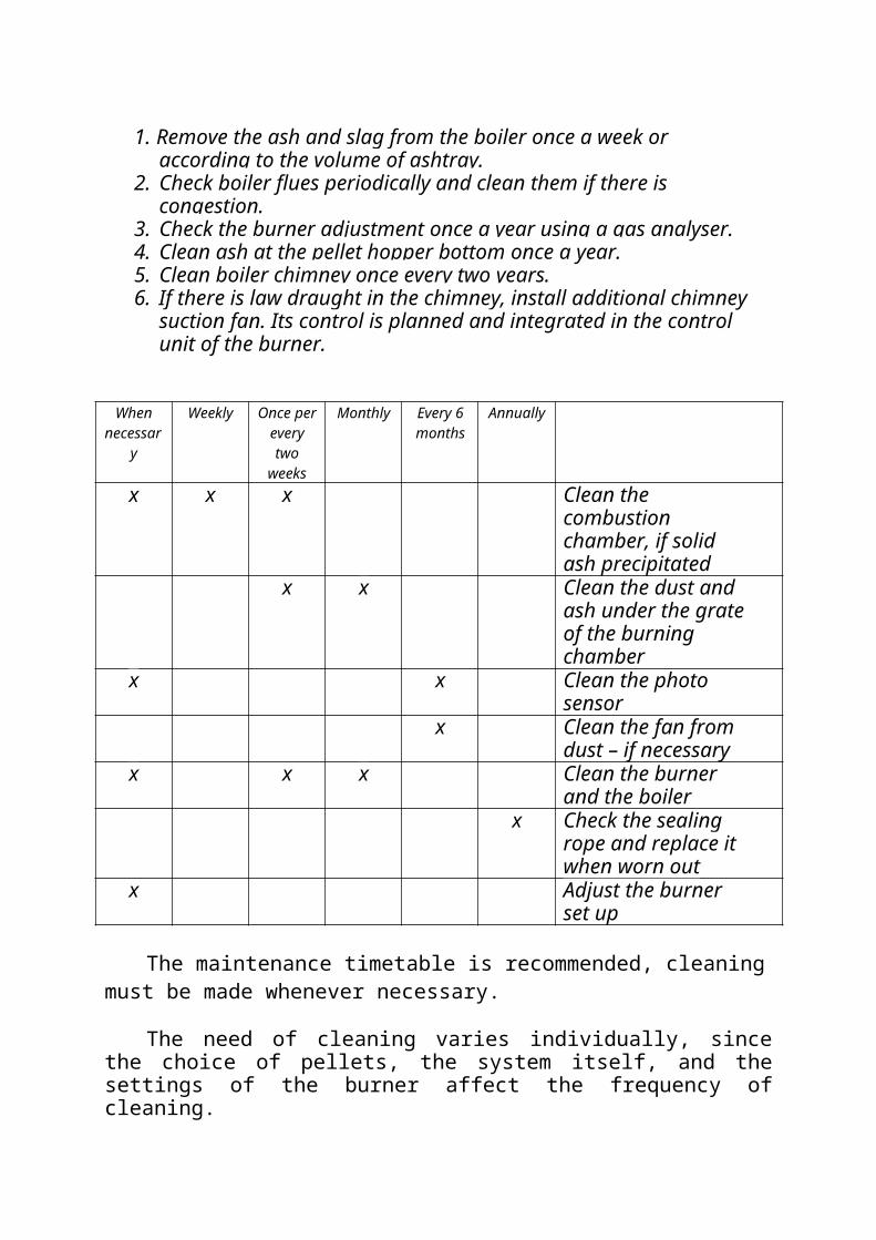
1. Remove the ash and slag from the boiler once a week or according to the volume of ashtray.
2. Check boiler flues periodically and clean them if there is congestion.3. Check the burner adjustment once a year using a gas analyser.4. Clean ash at the pellet hopper bottom once a year.5. Clean boiler chimney once every two years.6. If there is law draught in the chimney, install additional chimney
suction fan. Its control is planned and integrated in the control unit of the burner.
When Weekly Once per Monthly Every 6 Annually
necessary every two weeks
months
x x x Clean the combustion chamber, if solid ash precipitated
х х Clean the dust and ash under the grate of the burning chamber
х х Clean the photo sensor
х Clean the fan from dust – if necessary
х х х Clean the burner and the boiler
x Check the sealing rope and replace it when worn out
х Adjust the burner set up
The maintenance timetable is recommended, cleaning must be made whenever necessary.
The need of cleaning varies individually, since the choice of pellets, the system itself, and the settings of the burner affect the frequency of cleaning.
Unforeseen risks upon cleaning and maintenance. - Hand burn hazard.
Possible reason – high temperature in the burning chamber. This risk exists in case of unburned fuel pellet, as well as not cooled burner
when cleaning by user! It may occur upon cleaning and maintenance of the burner. The use of
special protective equipment (gloves) is recommended!
Electrical shock hazard The maintenance of the burner during operation as well as under voltage is prohibited! If short circuit or possible damage occur, authorised technician should be called. Touching the conducting parts is prohibited!
Dust in eye hazard May occur during work both upon cleaning and maintenance. The use of special protective equipment (safety goggles, tightly fitted) is recommended!
CAUTION!
Periodic cleaning, as well as supervision of the burner will prevent any incidents caused by faulty pellet fuel, incorrect slopes of burner and of screw conveyor, as well as incorrect combustion settings. Read this manual before installing and working with the burner. The manufacturer bears no responsibility!
A burner with properly adjusted settings operates well and cost-efficiently. If there are problems, please, contact the supplier for the removal of any defects or for setting up the burner.
POSSIBLE FAULTS AND TROUBLESHOOTING:
The verification shall be carried out only by a qualified electrical technician or an authorized by Mareli Company service center.The facility does not work:
- Check the hopper for sufficient quantity of pellets.- Check operation of the heater.- Check operation of the screw conveyor (whether it feeds pellets). Check
the flexible connection.
The facility does not start: (display is not illuminated)- Check fuses on the circuit board. ATTENTION! CUT OFF THE POWER
SUPPLY.- Check the power source for loose connections
Ignition failure:- the initial dose of pellets is insufficient (increase parameter 02)
Faulty heater - check it with a multimeter- High fan speed (decrease parameter 04)
Fuel feeding is OK, but the ignition fails:- Check the igniting heater with a multimeter;
- Check the voltage supplied to the igniting heater with a multimeter;- upon interruption of the facility's operation (poor combustion, etc.) check
condition of the flue and clean any debris and soot caused by the condensation.
It is important to replace faulty parts immediately!!!Always keep in stock additional photo sensor and heater for replacement.
At the end of the period, upon decommissioning the burner, clean the fuel surfaces from any deposits. Clean the screw conveyor and the hopper from residual sawdust. Cut off the burner power supply.
Additional information:
1. Cables of the thermal sensors can be extended up to 10 m.
2. Installation of the thermal sensors should be done with immersion sleeves or
applied under insulation pipes.
3. Sensors are part of the controller. Do not replace them by others.
4. Indoor thermostats with relay output must be used.
5. Bedroom thermostat cable section - 2x0.75mm2
6. The required chimney draught is at least 20 Pa. Install additional chimney
fan (controlled by the control unit of the burner) if the values are lower.
7. When wiring pumps or a chimney fan, the wiring inputs in the housing of the
burner must be used. If there is shortage of inputs, additional inputs must be
installed.
8. The burner ignites more easily at low fan speed. Carefully adjust
parameter 04. Recommended values are 15-18%.
9. The time for pellet loading before ignition - parameter 02 (first dose), must
be sufficient so that the fallen pellets
cover the holes in the combustion basin.
10. The initial ignition of pellets produces large volume of smoke. If
there is no additional chimney fan, smoke leakage is possible through the
seals on the boiler doors. The smoke usually disappears during normal
operation.
11. To achieve the desired output of the burner do the following:
• Start the burner and wait it to go to the 5-th degree of power.
• Remove the photoelectric cell from the connector and keep light
conditions of the photoelectric cell over 100 units.
• Disconnect the flexible connection from the burner and collect the
pellets passed from the conveyor into bag for 10 min.
• Weigh the pellets passed and multiply by the factor 0.03.
• The calculated value is the power in KW/h.
• Example: If the screw conveyor passes 1,300 g pellets for 10 min.
1,300x0.03 = 39 Kw/h - heating power.
12. It is recommended that the time for pellet feeding is half of the time for rest.
13. Indoor thermostat is connected to a filter for about 3 minutes. This
means that the START signal from the thermostat shall be read as
such 3 min. after it has been reported to the control unit. It is similarly
for the STOP signal. If there is signal of overheating from the back
combustion sensor, the fan of the burner continues to operate for
about 5 minutes in order to purge and cool.
14. If during the winter period the facility will not used, the installation must be
drained or filled with non-freezing fluid (polypropylene glycol).
Instructions for installer and service technician:
Screw conveyor installation:
Install the screw conveyor at an angle of 45 0 into the pellet hopper.Fill the hopper and plug the screw conveyor to 230V/ 50Hz. Wait for
the screw conveyor pipe to be filled with pellets and switch the plug to the burner. In order to ensure the normal free-fall of the pellets from the screw conveyor to the burner, the flexible connection must be well tensioned and the difference in levels between the screw conveyor outlet and the burner input shall be at least 40 cm.
Parameters adjustment:
The fuel process of the burner depends on several parameters. Fan speed (in percentages), time for feeding pellets from the screw conveyor (s), time for rest of the screw conveyor (s). These parameters are adjusted separately for the five degrees of power. The degrees are
upstream. It is not recommended that the power of the first or second degree is greater than the power of third, fourth, and fifth. For the recommended settings please refer to the manual for programming the controller of the pellet combustion system
If the facility does not operate satisfactorily:- Check the quality of pellets (must be free from dust). Upon normal
operation of the burner, the quantity of the pellets on the grate (combustion basin) must be such so that its holes are covered.
- Check the exhaust temperature (175- 240°C).- If the temperature is very high, decrease the pellets fed. If the
temperature is very low, increase the amount of input air.
It is important to replace faulty parts immediately!!! Always keep in stock additional photo sensor and heater for replacement.
The criterion for good operation of the burner is the colour of the flame - IT MUST BE YELLOW. When it is dark red, mixed with smoke it is most likely that the volume of input air is less than required for good combustion and must be increased.
Adjustment of the air affects essentially the combustion mode, the aim must be a calm, stable combustion, without residue.
Sometimes, if the initial loading dose for ignition is large (Parameter 02), "choking" of the burner may occur, i.e. it may not ignite and upon re-activation of the ignition (second attempt) the basin may clog up with pellets. The volume of the first dose must be decreased so as to avoid choking.
NOTE: It is desirable when adjusting the burner settings to use exhaust gas analyser.IMPORTANT:Default values of the parameters should not be taken for granted. The settings must be adjusted individually according to REQUIRED POWER, TILT OF THE SCREW CONVEYOR, QUALITY OF PELLETS, CHIMNEY DRAUGHT, CUSTOMER REQUIREMENTS!
2.9. Switching off the burner and the boilerSwitching off the automated pellet burner should be done according to the guidelines in its manual. After cooling of the boiler, the burner also should be
switched off. It is also recommended that the facility is cleaned from the accumulated ash.• An emergency stop of burner and boilerDuring operation of the automated pellet burner an emergency situations may arise. Some situations of this kind are recorded by the burner controller and a procedure for their preventionis automatically performed. The monitoring controller also indicates the burner status. In the event of an accident check the reason for its occurrence and take appropriate measures forits removal.
ATTENTION: In the event of emergency situation - overheating theboiler, the additionally mounted mandatory emergency thermostat is activated. Determine the cause of this accident and take appropriate measures for its removal. This thermostat must be manually switched by unscrewing and removing the protective cap and pressing its button until it switches, then replace back the protective cap.Also, the burner needs to be restarted by switching it off andon.
Faults and Troubleshooting
In the presence of a fault in the operation of the burner-boiler system, one should be familiar with the problems and how to solve them as described in the user manual for operation of steel hot water boiler, as well as in such for automated pellet burner. In the following table this information is supplemented by data that will be of assistance to the service technician.
No. Fault Reason Method of remedy
1 There is no pellet ignition Faulty heater for fuel ignition
Check the status of the electric heater
2 There is no feeding of pellets in the area of combustion in
the burner
Failure of the screw conveyor
Check the proper functioning of the drive gearmotor. Check the
connection of the engine to power control of the burner.
3 Smoke leakage of flue gases Leaks in the boiler Check connection to the chimney.
from the boiler Check seals of the boiler doors.
4 Deformation of the burner in the area of the combustion
process
Overheating of the burner structure
Replace the burner and change the combustion process settings.
5 Other problems Must be specified by the service technician
Consult the service team.
Troubleshooting
In case of a failure, try to repair it or inform a heating specialist. As an installation user you may only make repairs, which involve just simple replacement of the grate.
- In case of „first“ commissioning of the boiler condensation of water vapour on the heating surfaces of the heat exchanger may occur. This one-time process does not cause problems inthe operation of the facility;
- Operation of the automated pellet burner in modes, which exceed its heating power according to its technical parameters, is not allowed. In the case of exceeded rated thermal power of the automated pellet burner irrevocable deformations may occur in the area of the combustion chamber of the burner, which lead to its failure – in such cases the factory warranty of the burner is not recognized by the manufacturer.