Embed Size (px)
Citation preview
SM-AIO | | ManualHB140 | SM-AIO | | en | 17-22
VIPA System 300S
Analog signal modules - SM 33x(S)
www.vipa.com/en/service-support/manuals

300S_SM-AIO,5,EN - © 2017
VIPA GmbHOhmstr. 491074 HerzogenaurachTelephone: 09132-744-0Fax: 09132-744-1864Email: [email protected]: www.vipa.com
Table of contents1 Basics...................................................................................................................... 5
1.1 Copyright © VIPA GmbH ................................................................................. 51.2 Über dieses Handbuch..................................................................................... 61.3 Safety information............................................................................................. 7
2 Assembly and installation guidelines.................................................................. 82.1 Safety information for users.............................................................................. 82.2 Overview........................................................................................................... 92.3 Installation dimensions..................................................................................... 92.4 Assembly SPEED-Bus.................................................................................... 112.5 Assembly standard bus.................................................................................. 142.6 Cabling........................................................................................................... 162.7 Installation guidelines..................................................................................... 202.8 General data I/O modules.............................................................................. 222.8.1 General data................................................................................................ 23
3 Analog Input Modules.......................................................................................... 253.1 Principles........................................................................................................ 253.2 Parameterization - Basics............................................................................... 253.2.1 Parameterization by hardware configuration............................................... 263.2.2 Parameterization during runtime................................................................. 263.3 331-1KF01 - AI 8x13Bit ................................................................................. 293.3.1 331-1KF01 - AI 8x13Bit - Parametrization................................................... 323.3.2 331-1KF01 - Technical data......................................................................... 383.4 331-7Kx01 - AI 8(2)x12Bit ............................................................................. 433.4.1 Connection of sensors ................................................................................ 453.4.2 331-7Kx01 - AI 8(2)x12Bit - Parameterization............................................. 503.4.3 331-7Kx01 - AI 8(2)x12Bit - Diagnostics..................................................... 573.4.4 331-7KB01 - Technical data........................................................................ 623.4.5 331-7KF01 - Technical data......................................................................... 68
4 Analog Output Modules....................................................................................... 754.1 General........................................................................................................... 754.2 Connecting loads and actuators..................................................................... 754.3 Analog value representation........................................................................... 774.4 Parameterization - Basics............................................................................... 774.4.1 Parameterization by hardware configuration............................................... 774.4.2 Parameterization during run time by means of SFCs.................................. 784.5 Diagnostics .................................................................................................... 804.6 332-5HB01 - AO 2/4x12Bit U/I 2-channel....................................................... 844.6.1 Technical data.............................................................................................. 874.7 332-5HD01 - AO 2/4x12Bit U/I 4-channel...................................................... 904.7.1 Technical data.............................................................................................. 934.8 332-5HD50 - AO 4x12Bit I for manual operation............................................ 964.8.1 Manual operation......................................................................................... 984.8.2 Technical data.............................................................................................. 994.9 332-5HD60 - AO 4x12Bit U for manual operation........................................ 1024.9.1 Manual operation....................................................................................... 1044.9.2 Technical data............................................................................................ 105
VIPA System 300S Table of contents
HB140 | SM-AIO | | en | 17-22 3
5 Analog I/O Modules............................................................................................ 1085.1 General......................................................................................................... 1085.2 Analog value representation......................................................................... 1085.3 Parameterization........................................................................................... 1105.3.1 Parameterization by hardware configuration............................................. 1115.3.2 Parameterization during run time by means of SFCs................................ 1115.4 334-0KE00 - AI 4/AO 2x12Bit ...................................................................... 1135.4.1 Technical data............................................................................................ 115
6 Analog I/O Modules FAST - SPEED-Bus.......................................................... 1216.1 General......................................................................................................... 1216.2 Analog value representation......................................................................... 1216.3 Operating modes.......................................................................................... 1236.4 Addressing at SPEED-Bus........................................................................... 1236.5 Project engineering....................................................................................... 1246.5.1 Fast introduction........................................................................................ 1246.5.2 Preconditions............................................................................................. 1256.5.3 Steps of project engineering...................................................................... 1266.6 Parameterization.......................................................................................... 1296.6.1 Structure of the parameter bytes............................................................... 1296.7 SFC 193 - Oscilloscope-/FIFO function ....................................................... 1336.8 Example for the Oscilloscope function......................................................... 1366.8.1 Example for the FIFO function................................................................... 1386.9 Diagnostics................................................................................................... 1426.9.1 Process interrupts...................................................................................... 1446.10 331-7AF70 - AI 8x16Bit I ........................................................................... 1466.10.1 Technical data.......................................................................................... 1476.11 331-7BF70 - AI 8x16Bit U........................................................................... 1526.11.1 Technical data.......................................................................................... 153
VIPA System 300STable of contents
HB140 | SM-AIO | | en | 17-22 4
1 Basics1.1 Copyright © VIPA GmbH
This document contains proprietary information of VIPA and is not to be disclosed or usedexcept in accordance with applicable agreements.
This material is protected by the copyright laws. It may not be reproduced, distributed, oraltered in any fashion by any entity (either internal or external to VIPA), except in accord-ance with applicable agreements, contracts or licensing, without the express written con-sent of VIPA and the business management owner of the material.
For permission to reproduce or distribute, please contact: VIPA, Gesellschaft für Visuali-sierung und Prozessautomatisierung mbH Ohmstraße 4, D-91074 Herzogenaurach, Ger-many
Tel.: +49 9132 744 -0
Fax.: +49 9132 744-1864
EMail: [email protected]
http://www.vipa.com
Every effort has been made to ensure that the information contained inthis document was complete and accurate at the time of publishing. Nev-ertheless, the authors retain the right to modify the information.
This customer document describes all the hardware units and functionsknown at the present time. Descriptions may be included for units whichare not present at the customer site. The exact scope of delivery isdescribed in the respective purchase contract.
Hereby, VIPA GmbH declares that the products and systems are in compliance with theessential requirements and other relevant provisions. Conformity is indicated by the CEmarking affixed to the product.
For more information regarding CE marking and Declaration of Conformity (DoC), pleasecontact your local VIPA customer service organization.
VIPA, SLIO, System 100V, System 200V, System 300V, System 300S, System 400V,System 500S and Commander Compact are registered trademarks of VIPA Gesellschaftfür Visualisierung und Prozessautomatisierung mbH.
SPEED7 is a registered trademark of profichip GmbH.
SIMATIC, STEP, SINEC, TIA Portal, S7-300 and S7-400 are registered trademarks ofSiemens AG.
Microsoft and Windows are registered trademarks of Microsoft Inc., USA.
Portable Document Format (PDF) and Postscript are registered trademarks of AdobeSystems, Inc.
All other trademarks, logos and service or product marks specified herein are owned bytheir respective companies.
Contact your local VIPA Customer Service Organization representative if you wish toreport errors or questions regarding the contents of this document. If you are unable tolocate a customer service centre, contact VIPA as follows:
All Rights Reserved
CE Conformity Declaration
Conformity Information
Trademarks
Information product sup-port
VIPA System 300S Basics
Copyright © VIPA GmbH
HB140 | SM-AIO | | en | 17-22 5
VIPA GmbH, Ohmstraße 4, 91074 Herzogenaurach, Germany
Telefax: +49 9132 744-1204
EMail: [email protected]
Contact your local VIPA Customer Service Organization representative if you encounterproblems with the product or have questions regarding the product. If you are unable tolocate a customer service centre, contact VIPA as follows:
VIPA GmbH, Ohmstraße 4, 91074 Herzogenaurach, Germany
Tel.: +49 9132 744-1150 (Hotline)
EMail: [email protected]
1.2 Über dieses HandbuchThe manual is targeted at users who have a background in automation technology.
The manual consists of chapters. Every chapter provides a self-contained description of aspecific topic.
The following guides are available in the manual:
n An overall table of contents at the beginning of the manualn References with page numbers
The manual is available in:
n printed form, on papern in electronic form as PDF-file (Adobe Acrobat Reader)
Important passages in the text are highlighted by following icons and headings:
DANGER!Immediate or likely danger. Personal injury is possible.
CAUTION!Damages to property is likely if these warnings are not heeded.
Supplementary information and useful tips.
Technical support
Target audience
Structure of the manual
Guide to the document
Availability
Icons Headings
VIPA System 300SBasics
Über dieses Handbuch
HB140 | SM-AIO | | en | 17-22 6
1.3 Safety informationThe system is constructed and produced for:
n communication and process controln general control and automation tasksn industrial applicationsn operation within the environmental conditions specified in the technical datan installation into a cubicle
DANGER!This device is not certified for applications in
– in explosive environments (EX-zone)
The manual must be available to all personnel in the
n project design departmentn installation departmentn commissioningn operation
CAUTION!The following conditions must be met before using or commis-sioning the components described in this manual:– Hardware modifications to the process control system should only be
carried out when the system has been disconnected from power!– Installation and hardware modifications only by properly trained per-
sonnel.– The national rules and regulations of the respective country must be
satisfied (installation, safety, EMC ...)
National rules and regulations apply to the disposal of the unit!
Applications conformingwith specifications
Documentation
Disposal
VIPA System 300S Basics
Safety information
HB140 | SM-AIO | | en | 17-22 7
2 Assembly and installation guidelines2.1 Safety information for users
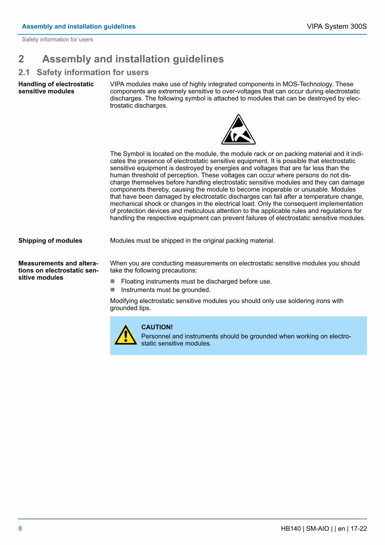
VIPA modules make use of highly integrated components in MOS-Technology. Thesecomponents are extremely sensitive to over-voltages that can occur during electrostaticdischarges. The following symbol is attached to modules that can be destroyed by elec-trostatic discharges.
The Symbol is located on the module, the module rack or on packing material and it indi-cates the presence of electrostatic sensitive equipment. It is possible that electrostaticsensitive equipment is destroyed by energies and voltages that are far less than thehuman threshold of perception. These voltages can occur where persons do not dis-charge themselves before handling electrostatic sensitive modules and they can damagecomponents thereby, causing the module to become inoperable or unusable. Modulesthat have been damaged by electrostatic discharges can fail after a temperature change,mechanical shock or changes in the electrical load. Only the consequent implementationof protection devices and meticulous attention to the applicable rules and regulations forhandling the respective equipment can prevent failures of electrostatic sensitive modules.
Modules must be shipped in the original packing material.
When you are conducting measurements on electrostatic sensitive modules you shouldtake the following precautions:
n Floating instruments must be discharged before use.n Instruments must be grounded.
Modifying electrostatic sensitive modules you should only use soldering irons withgrounded tips.
CAUTION!Personnel and instruments should be grounded when working on electro-static sensitive modules.
Handling of electrostaticsensitive modules
Shipping of modules
Measurements and altera-tions on electrostatic sen-sitive modules
VIPA System 300SAssembly and installation guidelines
Safety information for users
HB140 | SM-AIO | | en | 17-22 8
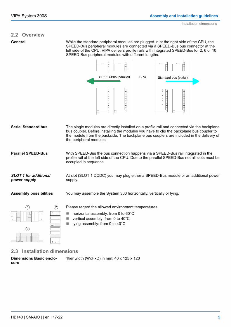
2.2 OverviewWhile the standard peripheral modules are plugged-in at the right side of the CPU, theSPEED-Bus peripheral modules are connected via a SPEED-Bus bus connector at theleft side of the CPU. VIPA delivers profile rails with integrated SPEED-Bus for 2, 6 or 10SPEED-Bus peripheral modules with different lengths.
The single modules are directly installed on a profile rail and connected via the backplanebus coupler. Before installing the modules you have to clip the backplane bus coupler tothe module from the backside. The backplane bus couplers are included in the delivery ofthe peripheral modules.
With SPEED-Bus the bus connection happens via a SPEED-Bus rail integrated in theprofile rail at the left side of the CPU. Due to the parallel SPEED-Bus not all slots must beoccupied in sequence.
At slot (SLOT 1 DCDC) you may plug either a SPEED-Bus module or an additional powersupply.
You may assemble the System 300 horizontally, vertically or lying.
Please regard the allowed environment temperatures:
n horizontal assembly: from 0 to 60°Cn vertical assembly: from 0 to 40°Cn lying assembly: from 0 to 40°C
2.3 Installation dimensions1tier width (WxHxD) in mm: 40 x 125 x 120
General
Serial Standard bus
Parallel SPEED-Bus
SLOT 1 for additionalpower supply
Assembly possibilities
Dimensions Basic enclo-sure
VIPA System 300S Assembly and installation guidelines
Installation dimensions
HB140 | SM-AIO | | en | 17-22 9
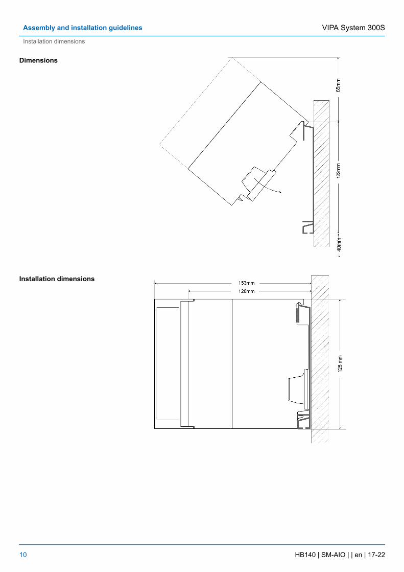
Dimensions
Installation dimensions
VIPA System 300SAssembly and installation guidelines
Installation dimensions
HB140 | SM-AIO | | en | 17-22 10
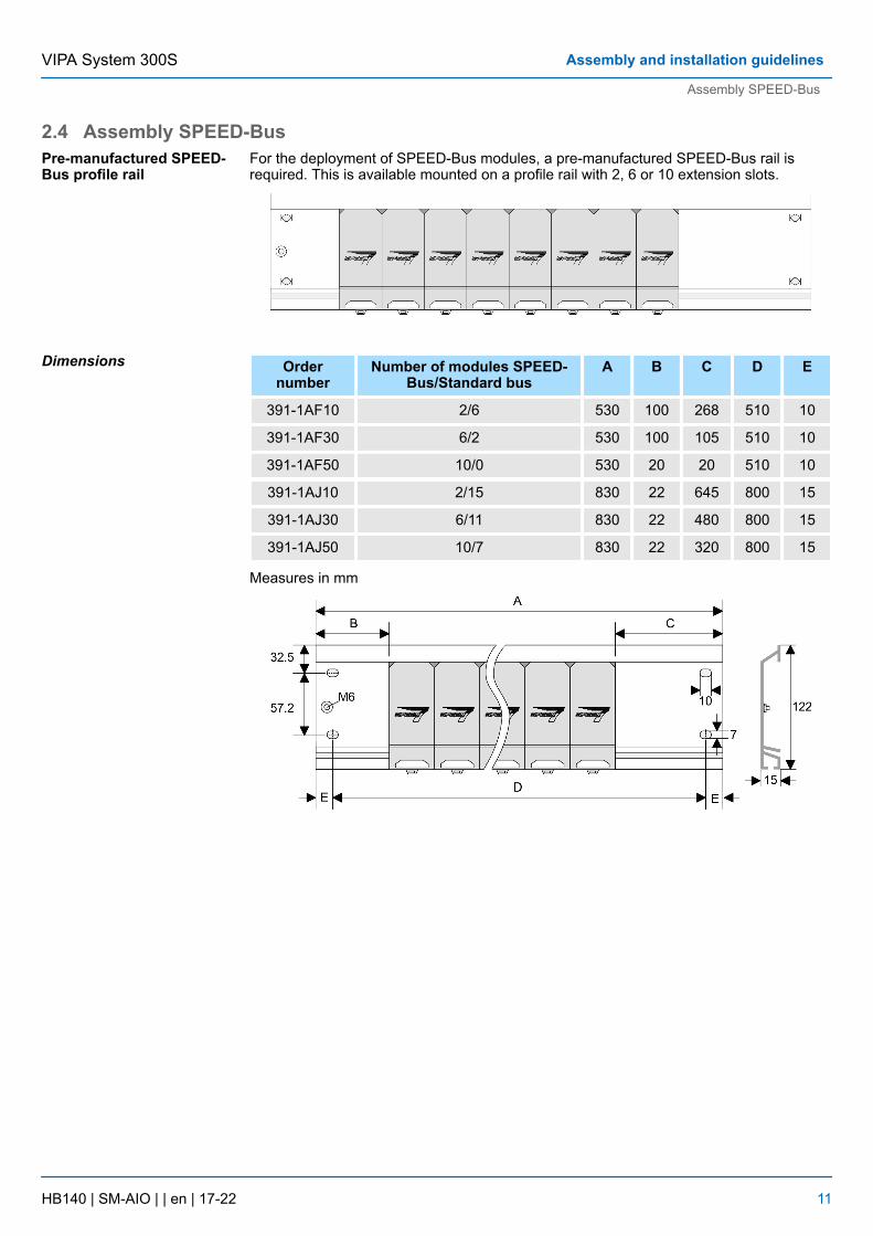
2.4 Assembly SPEED-BusFor the deployment of SPEED-Bus modules, a pre-manufactured SPEED-Bus rail isrequired. This is available mounted on a profile rail with 2, 6 or 10 extension slots.
Ordernumber
Number of modules SPEED-Bus/Standard bus
A B C D E
391-1AF10 2/6 530 100 268 510 10
391-1AF30 6/2 530 100 105 510 10
391-1AF50 10/0 530 20 20 510 10
391-1AJ10 2/15 830 22 645 800 15
391-1AJ30 6/11 830 22 480 800 15
391-1AJ50 10/7 830 22 320 800 15
Measures in mm
Pre-manufactured SPEED-Bus profile rail
Dimensions
VIPA System 300S Assembly and installation guidelines
Assembly SPEED-Bus
HB140 | SM-AIO | | en | 17-22 11
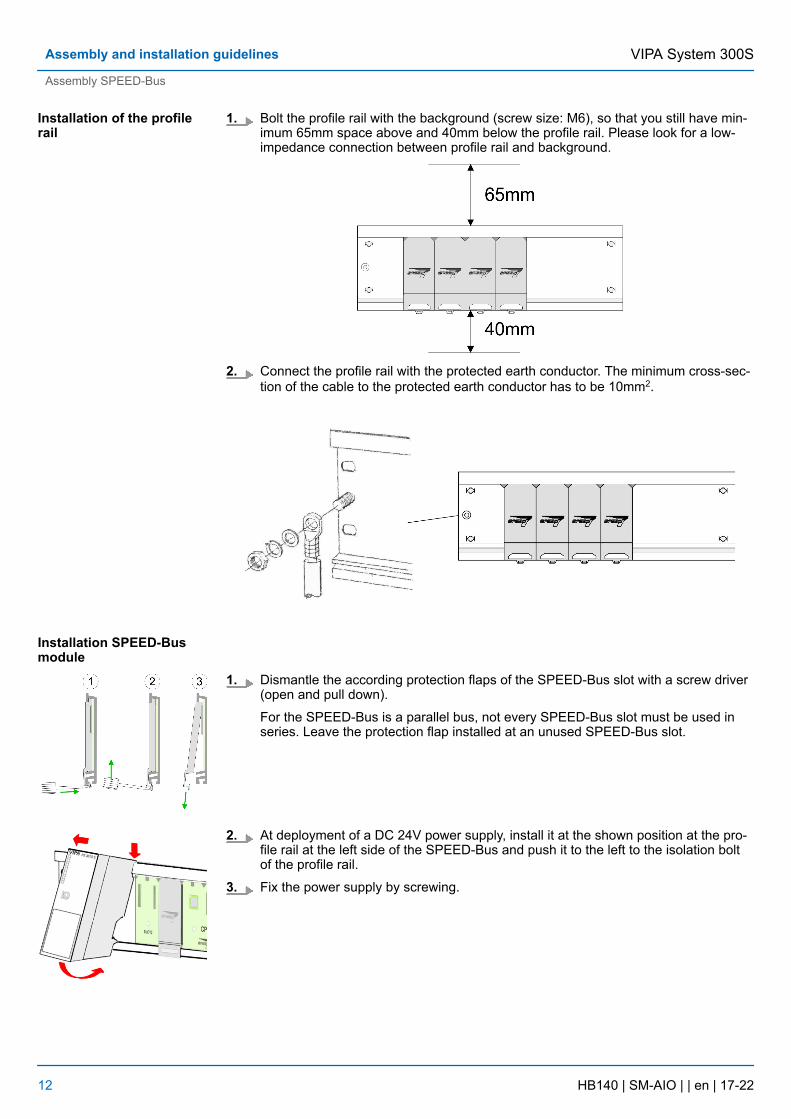
1. Bolt the profile rail with the background (screw size: M6), so that you still have min-imum 65mm space above and 40mm below the profile rail. Please look for a low-impedance connection between profile rail and background.
2. Connect the profile rail with the protected earth conductor. The minimum cross-sec-tion of the cable to the protected earth conductor has to be 10mm2.
1. Dismantle the according protection flaps of the SPEED-Bus slot with a screw driver(open and pull down).
For the SPEED-Bus is a parallel bus, not every SPEED-Bus slot must be used inseries. Leave the protection flap installed at an unused SPEED-Bus slot.
2. At deployment of a DC 24V power supply, install it at the shown position at the pro-file rail at the left side of the SPEED-Bus and push it to the left to the isolation boltof the profile rail.
3. Fix the power supply by screwing.
Installation of the profilerail
Installation SPEED-Busmodule
VIPA System 300SAssembly and installation guidelines
Assembly SPEED-Bus
HB140 | SM-AIO | | en | 17-22 12
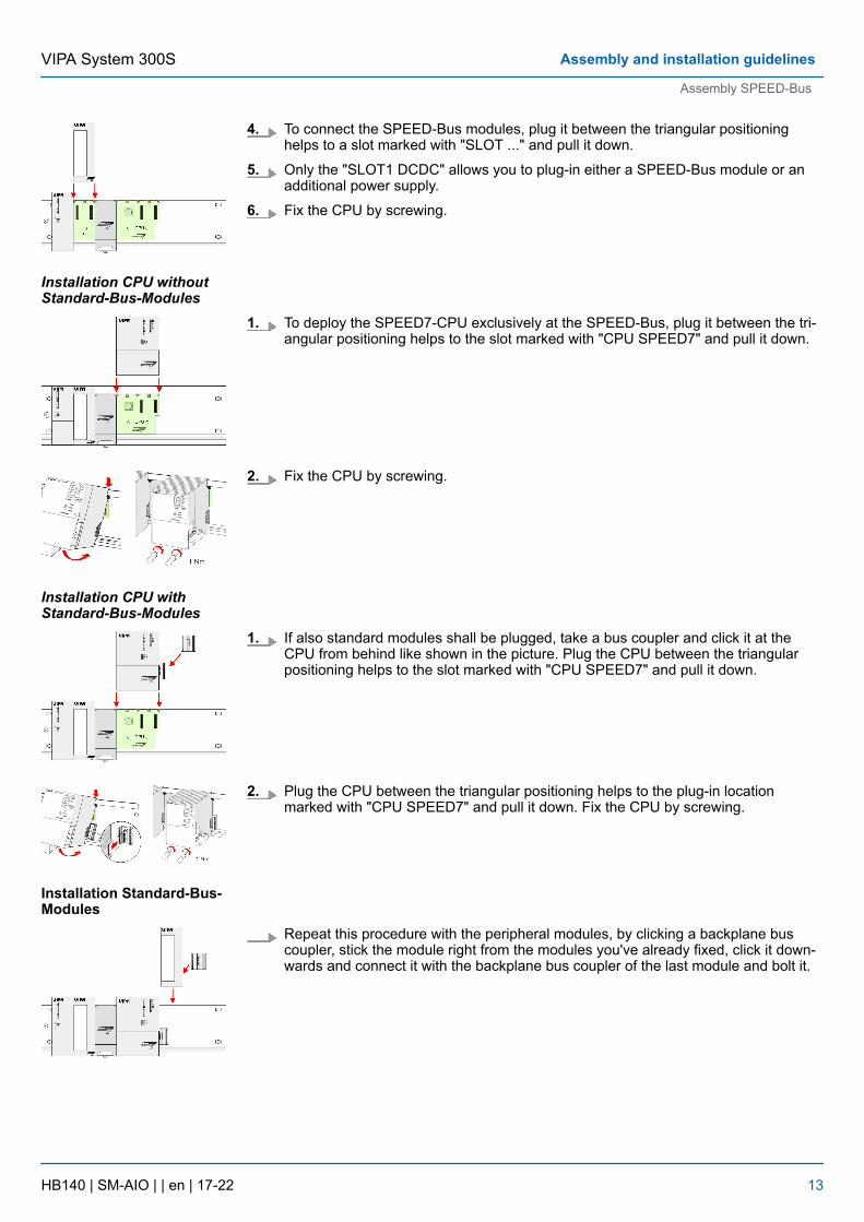
4. To connect the SPEED-Bus modules, plug it between the triangular positioninghelps to a slot marked with "SLOT ..." and pull it down.
5. Only the "SLOT1 DCDC" allows you to plug-in either a SPEED-Bus module or anadditional power supply.
6. Fix the CPU by screwing.
1. To deploy the SPEED7-CPU exclusively at the SPEED-Bus, plug it between the tri-angular positioning helps to the slot marked with "CPU SPEED7" and pull it down.
2. Fix the CPU by screwing.
1. If also standard modules shall be plugged, take a bus coupler and click it at theCPU from behind like shown in the picture. Plug the CPU between the triangularpositioning helps to the slot marked with "CPU SPEED7" and pull it down.
2. Plug the CPU between the triangular positioning helps to the plug-in locationmarked with "CPU SPEED7" and pull it down. Fix the CPU by screwing.
Repeat this procedure with the peripheral modules, by clicking a backplane buscoupler, stick the module right from the modules you've already fixed, click it down-wards and connect it with the backplane bus coupler of the last module and bolt it.
Installation CPU withoutStandard-Bus-Modules
Installation CPU withStandard-Bus-Modules
Installation Standard-Bus-Modules
VIPA System 300S Assembly and installation guidelines
Assembly SPEED-Bus
HB140 | SM-AIO | | en | 17-22 13
CAUTION!– The power supplies must be released before installation and repair
tasks, i.e. before handling with the power supply or with the cablingyou must disconnect current/voltage (pull plug, at fixed connectionswitch off the concerning fuse)!
– Installation and modifications only by properly trained personnel!
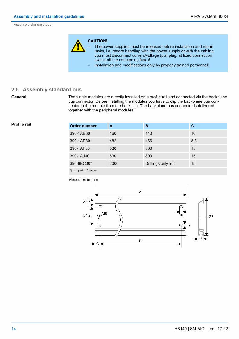
2.5 Assembly standard busThe single modules are directly installed on a profile rail and connected via the backplanebus connector. Before installing the modules you have to clip the backplane bus con-nector to the module from the backside. The backplane bus connector is deliveredtogether with the peripheral modules.
Order number A B C
390-1AB60 160 140 10
390-1AE80 482 466 8.3
390-1AF30 530 500 15
390-1AJ30 830 800 15
390-9BC00* 2000 Drillings only left 15*) Unit pack: 10 pieces
Measures in mm
General
Profile rail
VIPA System 300SAssembly and installation guidelines
Assembly standard bus
HB140 | SM-AIO | | en | 17-22 14
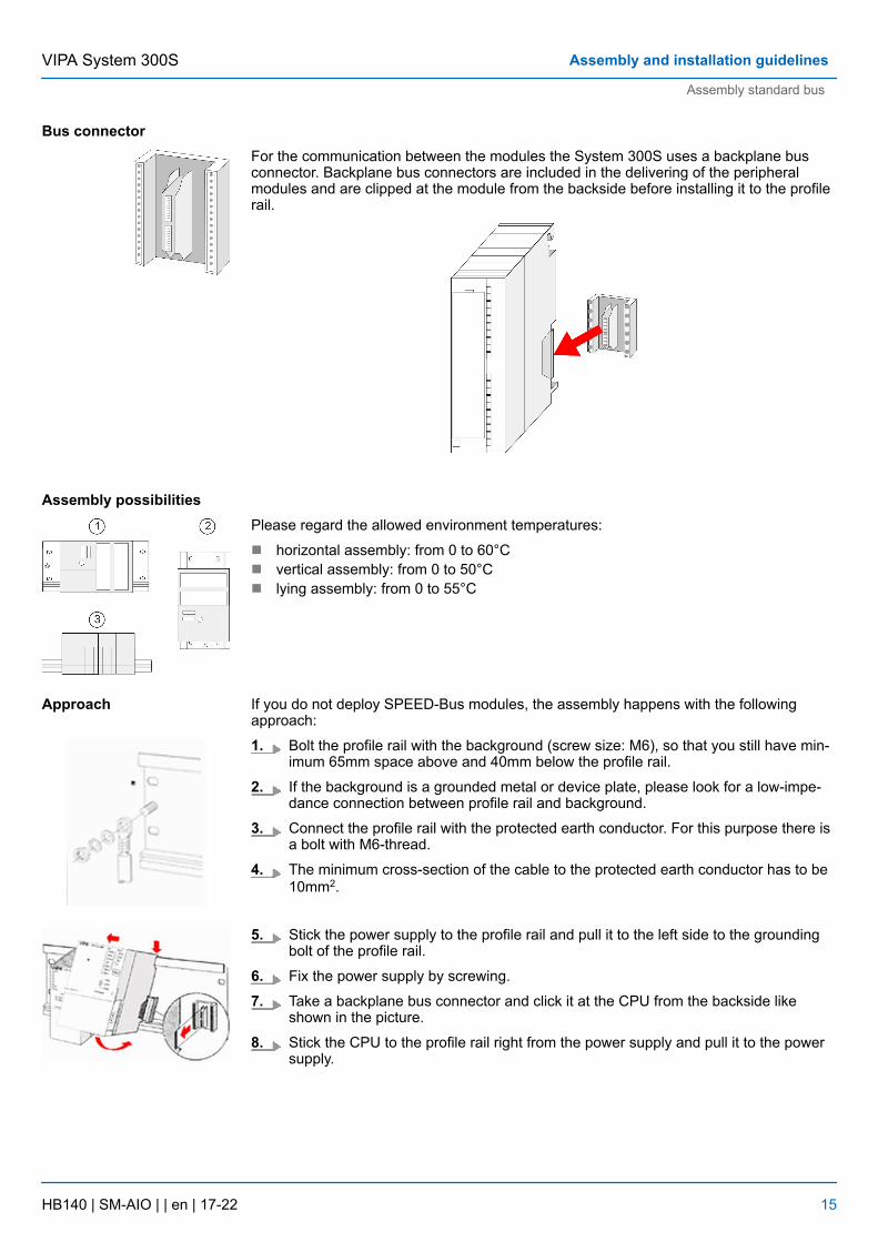
For the communication between the modules the System 300S uses a backplane busconnector. Backplane bus connectors are included in the delivering of the peripheralmodules and are clipped at the module from the backside before installing it to the profilerail.
Please regard the allowed environment temperatures:
n horizontal assembly: from 0 to 60°Cn vertical assembly: from 0 to 50°Cn lying assembly: from 0 to 55°C
If you do not deploy SPEED-Bus modules, the assembly happens with the followingapproach:
1. Bolt the profile rail with the background (screw size: M6), so that you still have min-imum 65mm space above and 40mm below the profile rail.
2. If the background is a grounded metal or device plate, please look for a low-impe-dance connection between profile rail and background.
3. Connect the profile rail with the protected earth conductor. For this purpose there isa bolt with M6-thread.
4. The minimum cross-section of the cable to the protected earth conductor has to be10mm2.
5. Stick the power supply to the profile rail and pull it to the left side to the groundingbolt of the profile rail.
6. Fix the power supply by screwing.
7. Take a backplane bus connector and click it at the CPU from the backside likeshown in the picture.
8. Stick the CPU to the profile rail right from the power supply and pull it to the powersupply.
Bus connector
Assembly possibilities
Approach
VIPA System 300S Assembly and installation guidelines
Assembly standard bus
HB140 | SM-AIO | | en | 17-22 15
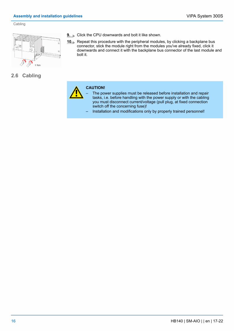
9. Click the CPU downwards and bolt it like shown.
10. Repeat this procedure with the peripheral modules, by clicking a backplane busconnector, stick the module right from the modules you've already fixed, click itdownwards and connect it with the backplane bus connector of the last module andbolt it.
2.6 Cabling
CAUTION!– The power supplies must be released before installation and repair
tasks, i.e. before handling with the power supply or with the cablingyou must disconnect current/voltage (pull plug, at fixed connectionswitch off the concerning fuse)!
– Installation and modifications only by properly trained personnel!
VIPA System 300SAssembly and installation guidelines
Cabling
HB140 | SM-AIO | | en | 17-22 16
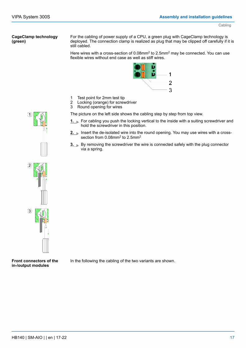
For the cabling of power supply of a CPU, a green plug with CageClamp technology isdeployed. The connection clamp is realized as plug that may be clipped off carefully if it isstill cabled.
Here wires with a cross-section of 0.08mm2 to 2.5mm2 may be connected. You can useflexible wires without end case as well as stiff wires.
1 Test point for 2mm test tip2 Locking (orange) for screwdriver3 Round opening for wires
The picture on the left side shows the cabling step by step from top view.
1. For cabling you push the locking vertical to the inside with a suiting screwdriver andhold the screwdriver in this position.
2. Insert the de-isolated wire into the round opening. You may use wires with a cross-section from 0.08mm2 to 2.5mm2
3. By removing the screwdriver the wire is connected safely with the plug connectorvia a spring.
In the following the cabling of the two variants are shown.
CageClamp technology(green)
Front connectors of thein-/output modules
VIPA System 300S Assembly and installation guidelines
Cabling
HB140 | SM-AIO | | en | 17-22 17
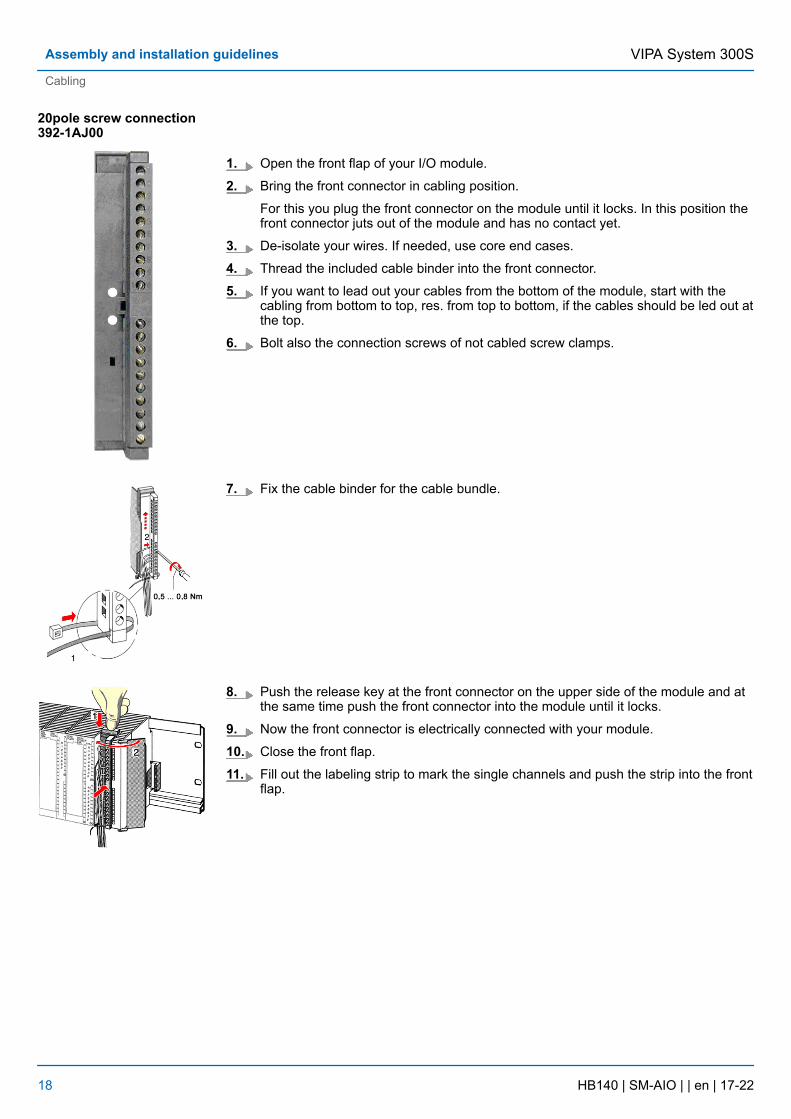
1. Open the front flap of your I/O module.
2. Bring the front connector in cabling position.
For this you plug the front connector on the module until it locks. In this position thefront connector juts out of the module and has no contact yet.
3. De-isolate your wires. If needed, use core end cases.
4. Thread the included cable binder into the front connector.
5. If you want to lead out your cables from the bottom of the module, start with thecabling from bottom to top, res. from top to bottom, if the cables should be led out atthe top.
6. Bolt also the connection screws of not cabled screw clamps.
7. Fix the cable binder for the cable bundle.
8. Push the release key at the front connector on the upper side of the module and atthe same time push the front connector into the module until it locks.
9. Now the front connector is electrically connected with your module.
10. Close the front flap.
11. Fill out the labeling strip to mark the single channels and push the strip into the frontflap.
20pole screw connection392-1AJ00
VIPA System 300SAssembly and installation guidelines
Cabling
HB140 | SM-AIO | | en | 17-22 18
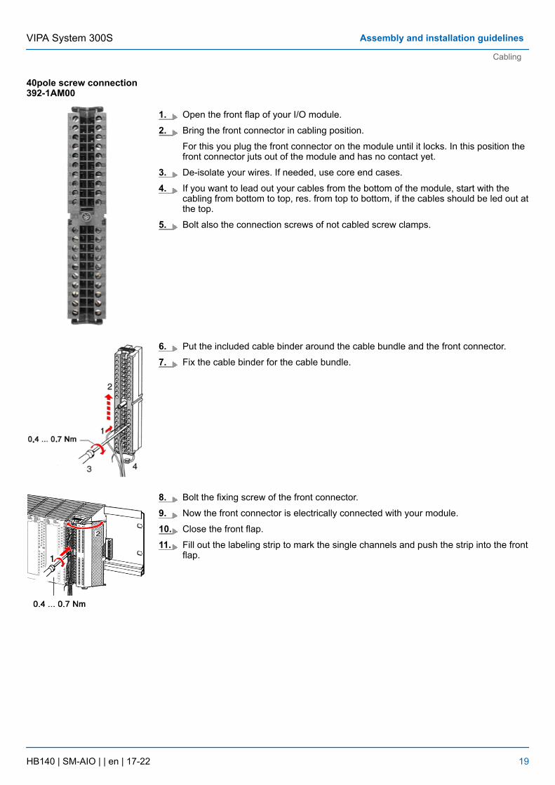
1. Open the front flap of your I/O module.
2. Bring the front connector in cabling position.
For this you plug the front connector on the module until it locks. In this position thefront connector juts out of the module and has no contact yet.
3. De-isolate your wires. If needed, use core end cases.
4. If you want to lead out your cables from the bottom of the module, start with thecabling from bottom to top, res. from top to bottom, if the cables should be led out atthe top.
5. Bolt also the connection screws of not cabled screw clamps.
6. Put the included cable binder around the cable bundle and the front connector.
7. Fix the cable binder for the cable bundle.
8. Bolt the fixing screw of the front connector.
9. Now the front connector is electrically connected with your module.
10. Close the front flap.
11. Fill out the labeling strip to mark the single channels and push the strip into the frontflap.
40pole screw connection392-1AM00
VIPA System 300S Assembly and installation guidelines
Cabling
HB140 | SM-AIO | | en | 17-22 19
2.7 Installation guidelinesThe installation guidelines contain information about the interference free deployment of aPLC system. There is the description of the ways, interference may occur in your PLC,how you can make sure the electromagnetic compatibility (EMC), and how you managethe isolation.
Electromagnetic compatibility (EMC) means the ability of an electrical device, to functionerror free in an electromagnetic environment without being interfered respectively withoutinterfering the environment.
The components of VIPA are developed for the deployment in industrial environmentsand meets high demands on the EMC. Nevertheless you should project an EMC planningbefore installing the components and take conceivable interference causes into account.
Electromagnetic interferences may interfere your control via different ways:
n Electromagnetic fields (RF coupling)n Magnetic fields with power frequencyn Bus systemn Power supplyn Protected earth conductor
Depending on the spreading medium (lead bound or lead free) and the distance to theinterference cause, interferences to your control occur by means of different couplingmechanisms.
There are:
n galvanic couplingn capacitive couplingn inductive couplingn radiant coupling
In the most times it is enough to take care of some elementary rules to guarantee theEMC. Please regard the following basic rules when installing your PLC.
n Take care of a correct area-wide grounding of the inactive metal parts when installingyour components.– Install a central connection between the ground and the protected earth conductor
system.– Connect all inactive metal extensive and impedance-low.– Please try not to use aluminium parts. Aluminium is easily oxidizing and is there-
fore less suitable for grounding.n When cabling, take care of the correct line routing.
– Organize your cabling in line groups (high voltage, current supply, signal and datalines).
– Always lay your high voltage lines and signal respectively data lines in separatechannels or bundles.
– Route the signal and data lines as near as possible beside ground areas (e.g.suspension bars, metal rails, tin cabinet).
General
What does EMC mean?
Possible interferencecauses
Basic rules for EMC
VIPA System 300SAssembly and installation guidelines
Installation guidelines
HB140 | SM-AIO | | en | 17-22 20
n Proof the correct fixing of the lead isolation.– Data lines must be laid isolated.– Analog lines must be laid isolated. When transmitting signals with small ampli-
tudes the one sided laying of the isolation may be favourable.– Lay the line isolation extensively on an isolation/protected earth conductor rail
directly after the cabinet entry and fix the isolation with cable clamps.– Make sure that the isolation/protected earth conductor rail is connected impe-
dance-low with the cabinet.– Use metallic or metallised plug cases for isolated data lines.
n In special use cases you should appoint special EMC actions.– Consider to wire all inductivities with erase links.– Please consider luminescent lamps can influence signal lines.
n Create a homogeneous reference potential and ground all electrical operating sup-plies when possible.– Please take care for the targeted employment of the grounding actions. The
grounding of the PLC serves for protection and functionality activity.– Connect installation parts and cabinets with your PLC in star topology with the
isolation/protected earth conductor system. So you avoid ground loops.– If there are potential differences between installation parts and cabinets, lay suffi-
ciently dimensioned potential compensation lines.
Electrical, magnetically and electromagnetic interference fields are weakened by meansof an isolation, one talks of absorption. Via the isolation rail, that is connected conductivewith the rack, interference currents are shunt via cable isolation to the ground. Here youhave to make sure, that the connection to the protected earth conductor is impedance-low, because otherwise the interference currents may appear as interference cause.
When isolating cables you have to regard the following:
n If possible, use only cables with isolation tangle.n The hiding power of the isolation should be higher than 80%.n Normally you should always lay the isolation of cables on both sides. Only by means
of the both-sided connection of the isolation you achieve high quality interferencesuppression in the higher frequency area. Only as exception you may also lay the iso-lation one-sided. Then you only achieve the absorption of the lower frequencies. Aone-sided isolation connection may be convenient, if:– the conduction of a potential compensating line is not possible.– analog signals (some mV respectively µA) are transferred.– foil isolations (static isolations) are used.
n With data lines always use metallic or metallised plugs for serial couplings. Fix theisolation of the data line at the plug rack. Do not lay the isolation on the PIN 1 of theplug bar!
n At stationary operation it is convenient to strip the insulated cable interruption freeand lay it on the isolation/protected earth conductor line.
n To fix the isolation tangles use cable clamps out of metal. The clamps must clasp theisolation extensively and have well contact.
n Lay the isolation on an isolation rail directly after the entry of the cable in the cabinet.Lead the isolation further on to your PLC and don't lay it on there again!
CAUTION!Please regard at installation!At potential differences between the grounding points, there may be acompensation current via the isolation connected at both sides.
Remedy: Potential compensation line
Isolation of conductors
VIPA System 300S Assembly and installation guidelines
Installation guidelines
HB140 | SM-AIO | | en | 17-22 21
2.8 General data I/O modulesn Peripheral modules with recessed labelingn Dimensions of the basic enclosure:
– 1tier width: (WxHxD) in mm: 40x125x120
n Wiring by means of spring pressure connections (CageClamps) at the front connectorn Core cross-section 0.08 ... 2.5mm2 or 1.5 mm2
n Total isolation of the wiring at module changen Potential separation of all modules to the backplane bus
Structure/dimensions
Reliability
VIPA System 300SAssembly and installation guidelines
General data I/O modules
HB140 | SM-AIO | | en | 17-22 22
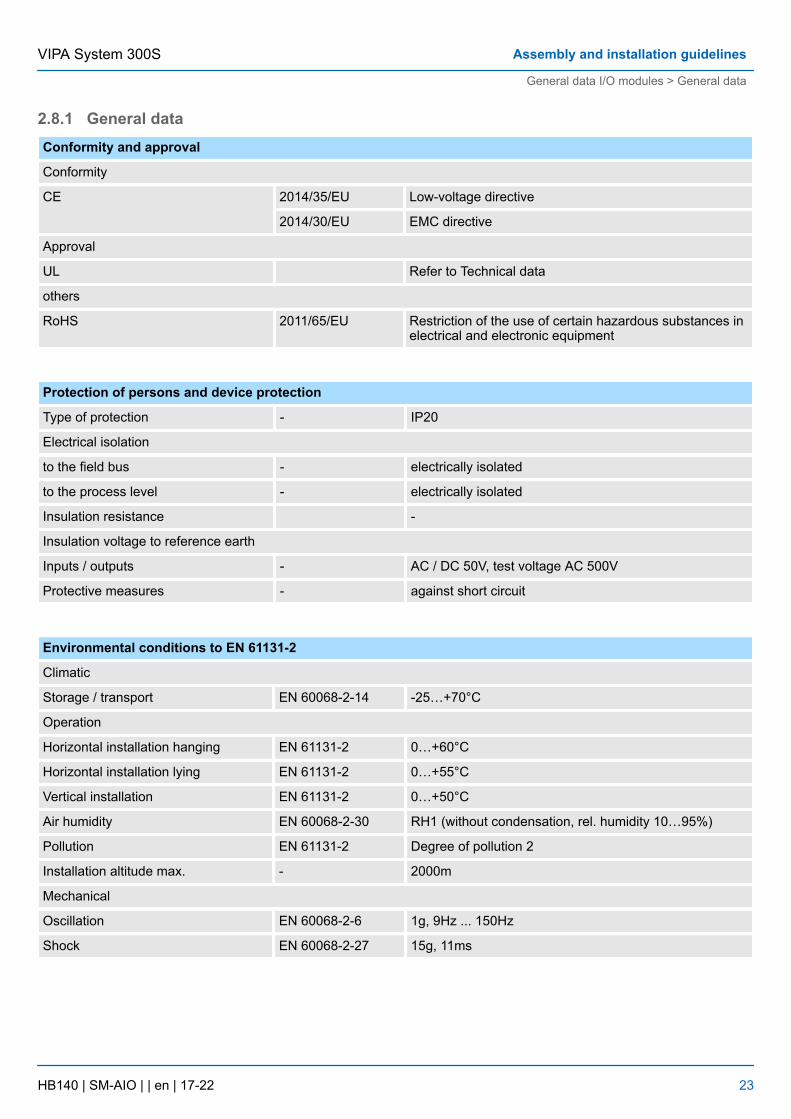
2.8.1 General dataConformity and approval
Conformity
CE 2014/35/EU Low-voltage directive
2014/30/EU EMC directive
Approval
UL Refer to Technical data
others
RoHS 2011/65/EU Restriction of the use of certain hazardous substances inelectrical and electronic equipment
Protection of persons and device protection
Type of protection - IP20
Electrical isolation
to the field bus - electrically isolated
to the process level - electrically isolated
Insulation resistance -
Insulation voltage to reference earth
Inputs / outputs - AC / DC 50V, test voltage AC 500V
Protective measures - against short circuit
Environmental conditions to EN 61131-2
Climatic
Storage / transport EN 60068-2-14 -25…+70°C
Operation
Horizontal installation hanging EN 61131-2 0…+60°C
Horizontal installation lying EN 61131-2 0…+55°C
Vertical installation EN 61131-2 0…+50°C
Air humidity EN 60068-2-30 RH1 (without condensation, rel. humidity 10…95%)
Pollution EN 61131-2 Degree of pollution 2
Installation altitude max. - 2000m
Mechanical
Oscillation EN 60068-2-6 1g, 9Hz ... 150Hz
Shock EN 60068-2-27 15g, 11ms
VIPA System 300S Assembly and installation guidelines
General data I/O modules > General data
HB140 | SM-AIO | | en | 17-22 23
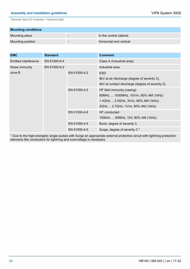
Mounting conditions
Mounting place - In the control cabinet
Mounting position - Horizontal and vertical
EMC Standard Comment
Emitted interference EN 61000-6-4 Class A (Industrial area)
Noise immunity
zone B
EN 61000-6-2 Industrial area
EN 61000-4-2 ESD
8kV at air discharge (degree of severity 3),
4kV at contact discharge (degree of severity 2)
EN 61000-4-3 HF field immunity (casing)
80MHz … 1000MHz, 10V/m, 80% AM (1kHz)
1.4GHz ... 2.0GHz, 3V/m, 80% AM (1kHz)
2GHz ... 2.7GHz, 1V/m, 80% AM (1kHz)
EN 61000-4-6 HF conducted
150kHz … 80MHz, 10V, 80% AM (1kHz)
EN 61000-4-4 Burst, degree of severity 3
EN 61000-4-5 Surge, degree of severity 3 **) Due to the high-energetic single pulses with Surge an appropriate external protective circuit with lightning protectionelements like conductors for lightning and overvoltage is necessary.
VIPA System 300SAssembly and installation guidelines
General data I/O modules > General data
HB140 | SM-AIO | | en | 17-22 24
3 Analog Input Modules3.1 Principles
For analog signals you have to use isolated cables to reduce interference. The cablescreening should be grounded at both ends. If there are differences in the potentialbetween the cable ends, there may occur a potential compensating current that could dis-turb the analog signals. In this case you should ground the cable screening only at oneend.
The analog input modules provide variant connecting possibilities for:
n Current sensorn Voltage senorn Resistance thermometern Thermocouplen Resistors
Please take care of the correct polarity when installing the measuringtransducer! Please install short circuits at non-used inputs by connectingthe positive contact with the channel ground of the according channel.
The analog input modules from VIPA do not have any measuring range plug. Themodules are parameterized via the hardware configurator or during runtime via SFCs.
The modules that are described in this chapter except the 331-1KF01 offer diagnosticsfunctions. The following errors may cause diagnostics:
n Error in the project engineering res. parameterizationn Wire break at current measuringn Measuring range overstepn Measuring range shortfalln Common Mode Errorn Lost process interruptn Failure of the external power supply
For diagnostic evaluation during runtime, you may use the SFCs 51 and 59. They allowyou to request detailed diagnostic information and to react to it.
3.2 Parameterization - BasicsThe analog input modules from VIPA do not have any measuring range plug, so themeasuring range is to be set by configuration. There are the following possibilities forparameterization:
n Parameterization by hardware configuration of Siemens SIMATIC manager or withWinPLC7 from VIPA.
n Parameterization during run time by means of SFCs.
Cables for analog signals
Connecting test probes
Parameterization
Diagnostic functions
Overview
VIPA System 300S Analog Input Modules
Parameterization - Basics
HB140 | SM-AIO | | en | 17-22 25
3.2.1 Parameterization by hardware configurationTo be compatible to the Siemens SIMATIC manager the following steps are to be accom-plished:
1. Start the hardware configurator from Siemens
2. Create a new project
3. Configure your CPU.
4. Link-up your System 300 modules in the plugged-in sequence starting with slot 4.Here the analog input modules of VIPA are to be projected as analog input modulesof Siemens:
ð The analog input modules can be found at the hardware catalog at SIMATIC300 > SM-300.
5. If needed parameterize the CPU respectively the modules. The parameter windowappears as soon as you double click on the according module. At this window theaccording parameter can be changed.
6. Save your project, switch the CPU to STOP and transfer your project to the CPU.As soon as the CPU is switched to RUN the parameters are transferred to the con-nected modules.
The following parameters can be adjusted at the analog input modules:
n Starting address of the input datan Measuring range, measuring type and integration timen Diagnostics and interrupt reaction (only 331-7Kx01)
3.2.2 Parameterization during runtimeBy using the SFCs 55, 56 and 57 you may change the parameters of the analog modulesduring runtime via the CPU. The time needed until the new parameterization is valid canlast up to a few ms. During this time the measuring value 7FFFh is issued. The followingexample shows the assignment of record set 1 to the module 331-7Kx01 during run time.
Varrec1 array [0...13] of BYTEretval INTbusy BOOLSet Record set 1:
L B#16#0 //Diagnostic disabled
T #rec1[0]L B#16#AA //Interference freq. suppression
T #rec1[1]L B#16#D4 //Meas. range Type S: 0100b
T #rec1[2] //Meas. type: Thermocouple
T #rec1[3] //Compensation internal: 1101b
T #rec1[4] //for all channels
T #rec1[5]L B#16#7F //Upper limit value
Parameters
Example
VIPA System 300SAnalog Input Modules
Parameterization - Basics > Parameterization during runtime
HB140 | SM-AIO | | en | 17-22 26
T #rec1[6] //channel 0: 7FFFh
L B#16#FFT #rec1[7]L B#16#80 //Lower limit value
T #rec1[12] //channel 2: 8000h
L B#16#00T #rec1[13]
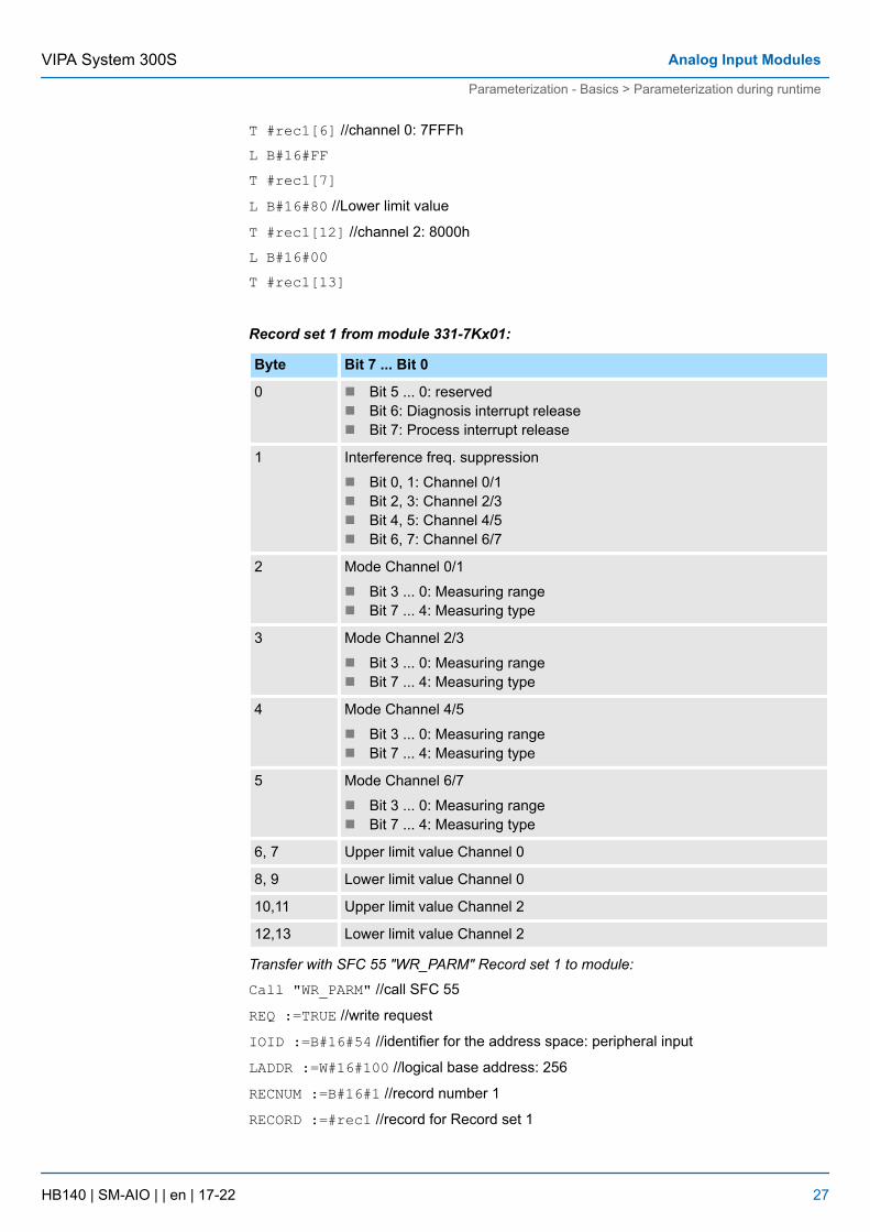
Record set 1 from module 331-7Kx01:
Byte Bit 7 ... Bit 0
0 n Bit 5 ... 0: reservedn Bit 6: Diagnosis interrupt releasen Bit 7: Process interrupt release
1 Interference freq. suppression
n Bit 0, 1: Channel 0/1n Bit 2, 3: Channel 2/3n Bit 4, 5: Channel 4/5n Bit 6, 7: Channel 6/7
2 Mode Channel 0/1
n Bit 3 ... 0: Measuring rangen Bit 7 ... 4: Measuring type
3 Mode Channel 2/3
n Bit 3 ... 0: Measuring rangen Bit 7 ... 4: Measuring type
4 Mode Channel 4/5
n Bit 3 ... 0: Measuring rangen Bit 7 ... 4: Measuring type
5 Mode Channel 6/7
n Bit 3 ... 0: Measuring rangen Bit 7 ... 4: Measuring type
6, 7 Upper limit value Channel 0
8, 9 Lower limit value Channel 0
10,11 Upper limit value Channel 2
12,13 Lower limit value Channel 2
Transfer with SFC 55 "WR_PARM" Record set 1 to module:
Call "WR_PARM" //call SFC 55
REQ :=TRUE //write request
IOID :=B#16#54 //identifier for the address space: peripheral input
LADDR :=W#16#100 //logical base address: 256
RECNUM :=B#16#1 //record number 1
RECORD :=#rec1 //record for Record set 1
VIPA System 300S Analog Input Modules
Parameterization - Basics > Parameterization during runtime
HB140 | SM-AIO | | en | 17-22 27
RET_VAL :=#retval //return value (0: no error <> 0: error code)
BUSY :=#busy //BUSY = 1: the write operation has not been completed
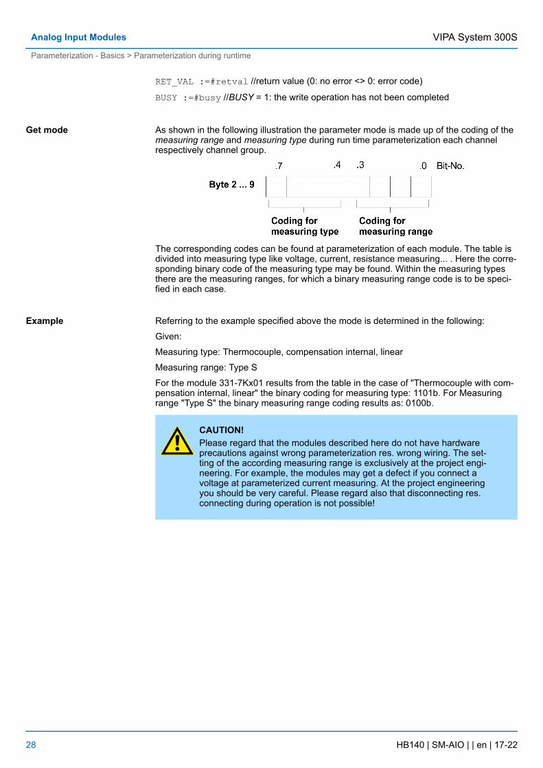
As shown in the following illustration the parameter mode is made up of the coding of themeasuring range and measuring type during run time parameterization each channelrespectively channel group.
The corresponding codes can be found at parameterization of each module. The table isdivided into measuring type like voltage, current, resistance measuring... . Here the corre-sponding binary code of the measuring type may be found. Within the measuring typesthere are the measuring ranges, for which a binary measuring range code is to be speci-fied in each case.
Referring to the example specified above the mode is determined in the following:
Given:
Measuring type: Thermocouple, compensation internal, linear
Measuring range: Type S
For the module 331-7Kx01 results from the table in the case of "Thermocouple with com-pensation internal, linear" the binary coding for measuring type: 1101b. For Measuringrange "Type S" the binary measuring range coding results as: 0100b.
CAUTION!Please regard that the modules described here do not have hardwareprecautions against wrong parameterization res. wrong wiring. The set-ting of the according measuring range is exclusively at the project engi-neering. For example, the modules may get a defect if you connect avoltage at parameterized current measuring. At the project engineeringyou should be very careful. Please regard also that disconnecting res.connecting during operation is not possible!
Get mode
Example
VIPA System 300SAnalog Input Modules
Parameterization - Basics > Parameterization during runtime
HB140 | SM-AIO | | en | 17-22 28
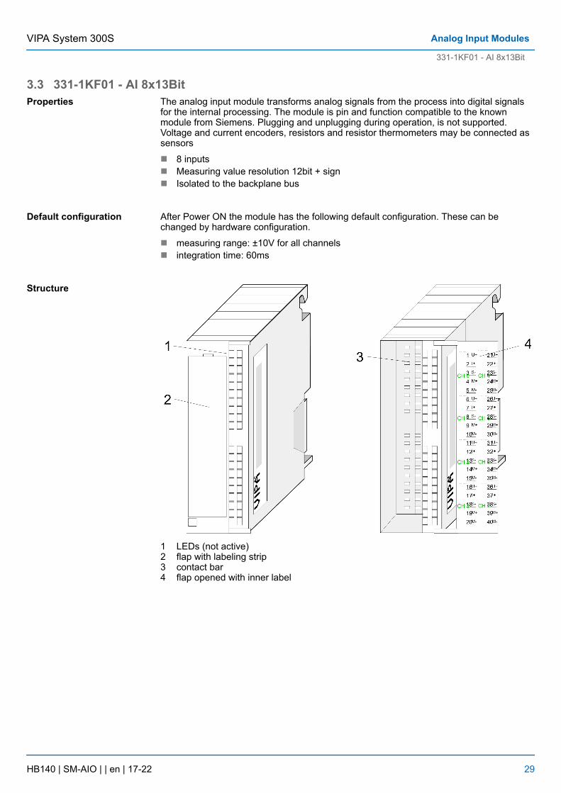
3.3 331-1KF01 - AI 8x13BitThe analog input module transforms analog signals from the process into digital signalsfor the internal processing. The module is pin and function compatible to the knownmodule from Siemens. Plugging and unplugging during operation, is not supported.Voltage and current encoders, resistors and resistor thermometers may be connected assensors
n 8 inputsn Measuring value resolution 12bit + signn Isolated to the backplane bus
After Power ON the module has the following default configuration. These can bechanged by hardware configuration.
n measuring range: ±10V for all channelsn integration time: 60ms
1 LEDs (not active)2 flap with labeling strip3 contact bar4 flap opened with inner label
Properties
Default configuration
Structure
VIPA System 300S Analog Input Modules
331-1KF01 - AI 8x13Bit
HB140 | SM-AIO | | en | 17-22 29
Pin Assignment Connection
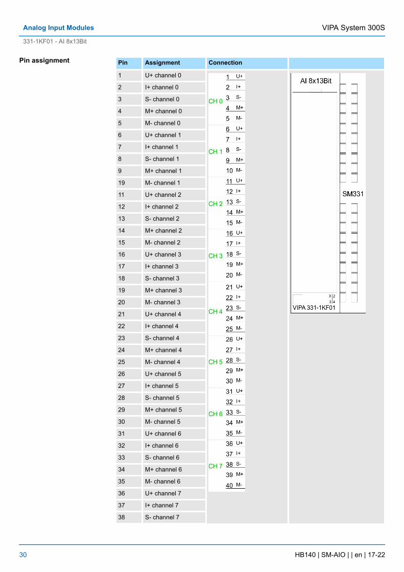
1 U+ channel 0
2 I+ channel 0
3 S- channel 0
4 M+ channel 0
5 M- channel 0
6 U+ channel 1
7 I+ channel 1
8 S- channel 1
9 M+ channel 1
19 M- channel 1
11 U+ channel 2
12 I+ channel 2
13 S- channel 2
14 M+ channel 2
15 M- channel 2
16 U+ channel 3
17 I+ channel 3
18 S- channel 3
19 M+ channel 3
20 M- channel 3
21 U+ channel 4
22 I+ channel 4
23 S- channel 4
24 M+ channel 4
25 M- channel 4
26 U+ channel 5
27 I+ channel 5
28 S- channel 5
29 M+ channel 5
30 M- channel 5
31 U+ channel 6
32 I+ channel 6
33 S- channel 6
34 M+ channel 6
35 M- channel 6
36 U+ channel 7
37 I+ channel 7
38 S- channel 7
Pin assignment
VIPA System 300SAnalog Input Modules
331-1KF01 - AI 8x13Bit
HB140 | SM-AIO | | en | 17-22 30
Pin Assignment Connection
39 M+ channel 7
40 M- channel 7
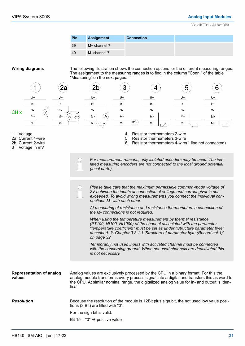
The following illustration shows the connection options for the different measuring ranges.The assignment to the measuring ranges is to find in the column "Conn." of the table"Measuring" on the next pages.
1 Voltage2a Current 4-wire2b Current 2-wire3 Voltage in mV
4 Resistor thermometers 2-wire5 Resistor thermometers 3-wire6 Resistor thermometers 4-wire(1 line not connected)
For measurement reasons, only isolated encoders may be used. The iso-lated measuring encoders are not connected to the local ground potential(local earth).
Please take care that the maximum permissible common-mode voltage of2V between the inputs at connection of voltage and current giver is notexceeded. To avoid wrong measurements you connect the individual con-nections M- with each other.
At measuring of resistance and resistance thermometers a connection ofthe M- connections is not required.
When using the temperature measurement by thermal resistance(PT100, NI100, NI1000) of the channel associated with the parameter"temperature coefficient" must be set as under "Structure parameter byte"described. Ä Chapter 3.3.1.1 ‘Structure of parameter byte (Record set 1)’on page 32
Temporarily not used inputs with activated channel must be connectedwith the concerning ground. When not used channels are deactivated thisis not necessary.
Analog values are exclusively processed by the CPU in a binary format. For this theanalog module transforms every process signal into a digital and transfers this as word tothe CPU. At similar nominal range, the digitalized analog value for in- and output is iden-tical.
Because the resolution of the module is 12Bit plus sign bit, the not used low value posi-tions (3 Bit) are filled with "0".
For the sign bit is valid:
Bit 15 = "0" à positive value
Wiring diagrams
Representation of analogvalues
Resolution
VIPA System 300S Analog Input Modules
331-1KF01 - AI 8x13Bit
HB140 | SM-AIO | | en | 17-22 31
Bit 15 = "1" à negative value
Resolution Analog value
High-Byte Low-Byte
Bit number 15 14 13 12 11 10 9 8 7 6 5 4 3 2 1 0
Value SG 214 213 212 211 210 29 28 27 26 25 24 23 22 21 20
12bit + sign SG Measuring value 0 0 0
3.3.1 331-1KF01 - AI 8x13Bit - ParametrizationAfter Power ON the module is set to ±10V for all channels with an integration time of60ms. Via a hardware configuration you may parameterize the channels individually.
1. Start the hardware configurator with the project the analog modules are to be con-figured.
2. To place the analog module open the hardware catalog. There the module can befound at SIMATIC 300/SM-300/AI-300, order no.: 6ES7 331-1KF01-0AB0.
3. Choose the according module and drag & drop it to the concerning slot in the hard-ware configurator.
Via double click on the wanted module in the hardware configurator you open the con-cerning parameter window. You may alter the following parameters:
n Start address of the data of the module stored in the CPUn Measuring range, measuring type and integration times for all of the 8 channels
n Save and compile your projectn Set your CPU to STOPn Transfer your project into the CPU
As soon as you switch the CPU into RUN, the parameters are transmitted to the analoginput module. More detailed information about the parameters can be found on the fol-lowing pages.
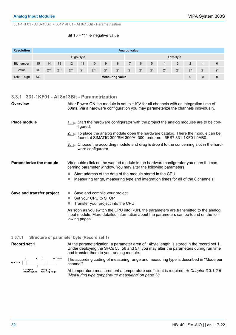
3.3.1.1 Structure of parameter byte (Record set 1)At the parameterization, a parameter area of 14byte length is stored in the record set 1.Under deploying the SFCs 55, 56 and 57, you may alter the parameters during run timeand transfer them to your analog module.
The according coding of measuring range and measuring type is described in "Mode perchannel".
At temperature measurement a temperature coefficient is required. Ä Chapter 3.3.1.2.5‘Measuring type temperature measuring’ on page 38
Overview
Place module
Parameterize the module
Save and transfer project
Record set 1
VIPA System 300SAnalog Input Modules
331-1KF01 - AI 8x13Bit > 331-1KF01 - AI 8x13Bit - Parametrization
HB140 | SM-AIO | | en | 17-22 32
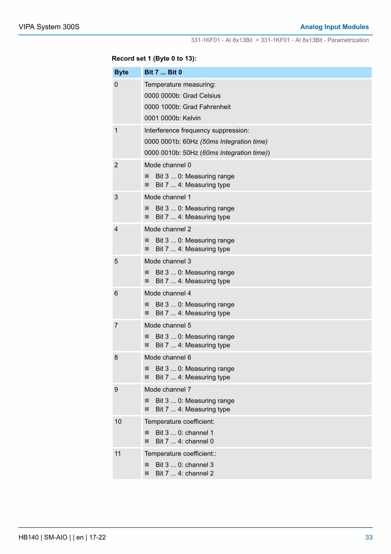
Record set 1 (Byte 0 to 13):
Byte Bit 7 ... Bit 0
0 Temperature measuring:
0000 0000b: Grad Celsius
0000 1000b: Grad Fahrenheit
0001 0000b: Kelvin
1 Interference frequency suppression:
0000 0001b: 60Hz (50ms Integration time)
0000 0010b: 50Hz (60ms Integration time))
2 Mode channel 0
n Bit 3 ... 0: Measuring rangen Bit 7 ... 4: Measuring type
3 Mode channel 1
n Bit 3 ... 0: Measuring rangen Bit 7 ... 4: Measuring type
4 Mode channel 2
n Bit 3 ... 0: Measuring rangen Bit 7 ... 4: Measuring type
5 Mode channel 3
n Bit 3 ... 0: Measuring rangen Bit 7 ... 4: Measuring type
6 Mode channel 4
n Bit 3 ... 0: Measuring rangen Bit 7 ... 4: Measuring type
7 Mode channel 5
n Bit 3 ... 0: Measuring rangen Bit 7 ... 4: Measuring type
8 Mode channel 6
n Bit 3 ... 0: Measuring rangen Bit 7 ... 4: Measuring type
9 Mode channel 7
n Bit 3 ... 0: Measuring rangen Bit 7 ... 4: Measuring type
10 Temperature coefficient:
n Bit 3 ... 0: channel 1n Bit 7 ... 4: channel 0
11 Temperature coefficient::
n Bit 3 ... 0: channel 3n Bit 7 ... 4: channel 2
VIPA System 300S Analog Input Modules
331-1KF01 - AI 8x13Bit > 331-1KF01 - AI 8x13Bit - Parametrization
HB140 | SM-AIO | | en | 17-22 33
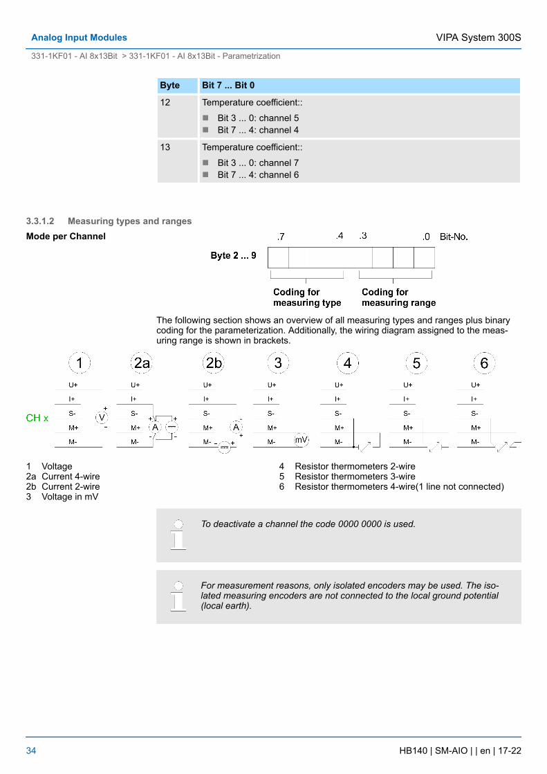
Byte Bit 7 ... Bit 0
12 Temperature coefficient::
n Bit 3 ... 0: channel 5n Bit 7 ... 4: channel 4
13 Temperature coefficient::
n Bit 3 ... 0: channel 7n Bit 7 ... 4: channel 6
3.3.1.2 Measuring types and ranges
The following section shows an overview of all measuring types and ranges plus binarycoding for the parameterization. Additionally, the wiring diagram assigned to the meas-uring range is shown in brackets.
1 Voltage2a Current 4-wire2b Current 2-wire3 Voltage in mV
4 Resistor thermometers 2-wire5 Resistor thermometers 3-wire6 Resistor thermometers 4-wire(1 line not connected)
To deactivate a channel the code 0000 0000 is used.
For measurement reasons, only isolated encoders may be used. The iso-lated measuring encoders are not connected to the local ground potential(local earth).
Mode per Channel
VIPA System 300SAnalog Input Modules
331-1KF01 - AI 8x13Bit > 331-1KF01 - AI 8x13Bit - Parametrization
HB140 | SM-AIO | | en | 17-22 34
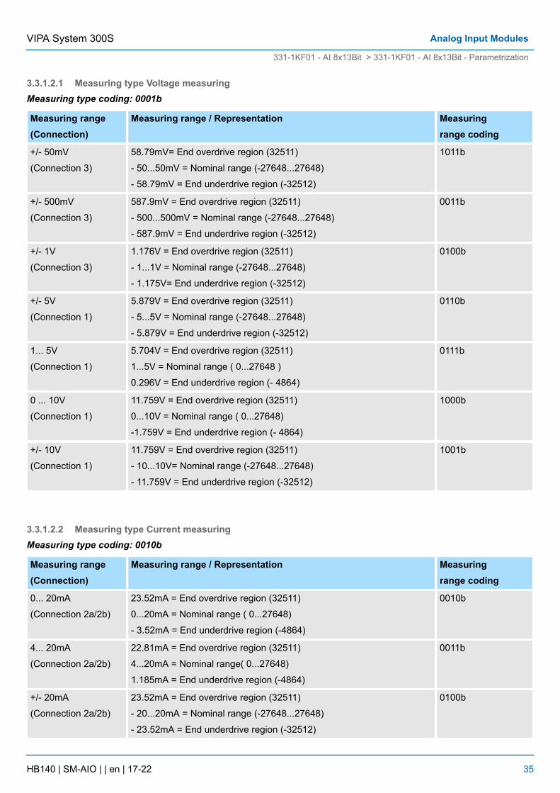
3.3.1.2.1 Measuring type Voltage measuringMeasuring type coding: 0001b
Measuring range(Connection)
Measuring range / Representation Measuringrange coding
+/- 50mV
(Connection 3)
58.79mV= End overdrive region (32511)
- 50...50mV = Nominal range (-27648...27648)
- 58.79mV = End underdrive region (-32512)
1011b
+/- 500mV
(Connection 3)
587.9mV = End overdrive region (32511)
- 500...500mV = Nominal range (-27648...27648)
- 587.9mV = End underdrive region (-32512)
0011b
+/- 1V
(Connection 3)
1.176V = End overdrive region (32511)
- 1...1V = Nominal range (-27648...27648)
- 1.175V= End underdrive region (-32512)
0100b
+/- 5V
(Connection 1)
5.879V = End overdrive region (32511)
- 5...5V = Nominal range (-27648...27648)
- 5.879V = End underdrive region (-32512)
0110b
1... 5V
(Connection 1)
5.704V = End overdrive region (32511)
1...5V = Nominal range ( 0...27648 )
0.296V = End underdrive region (- 4864)
0111b
0 ... 10V
(Connection 1)
11.759V = End overdrive region (32511)
0...10V = Nominal range ( 0...27648)
-1.759V = End underdrive region (- 4864)
1000b
+/- 10V
(Connection 1)
11.759V = End overdrive region (32511)
- 10...10V= Nominal range (-27648...27648)
- 11.759V = End underdrive region (-32512)
1001b
3.3.1.2.2 Measuring type Current measuringMeasuring type coding: 0010b
Measuring range(Connection)
Measuring range / Representation Measuringrange coding
0... 20mA
(Connection 2a/2b)
23.52mA = End overdrive region (32511)
0...20mA = Nominal range ( 0...27648)
- 3.52mA = End underdrive region (-4864)
0010b
4... 20mA
(Connection 2a/2b)
22.81mA = End overdrive region (32511)
4...20mA = Nominal range( 0...27648)
1.185mA = End underdrive region (-4864)
0011b
+/- 20mA
(Connection 2a/2b)
23.52mA = End overdrive region (32511)
- 20...20mA = Nominal range (-27648...27648)
- 23.52mA = End underdrive region (-32512)
0100b
VIPA System 300S Analog Input Modules
331-1KF01 - AI 8x13Bit > 331-1KF01 - AI 8x13Bit - Parametrization
HB140 | SM-AIO | | en | 17-22 35
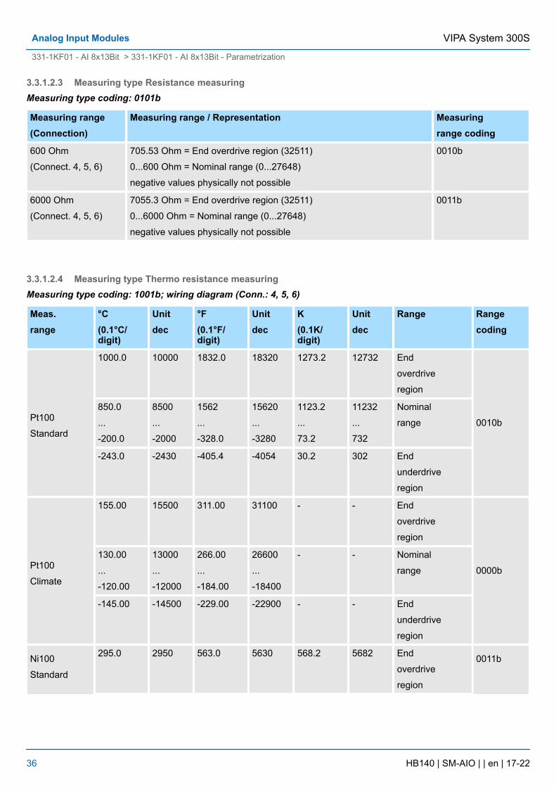
3.3.1.2.3 Measuring type Resistance measuringMeasuring type coding: 0101b
Measuring range(Connection)
Measuring range / Representation Measuringrange coding
600 Ohm
(Connect. 4, 5, 6)
705.53 Ohm = End overdrive region (32511)
0...600 Ohm = Nominal range (0...27648)
negative values physically not possible
0010b
6000 Ohm
(Connect. 4, 5, 6)
7055.3 Ohm = End overdrive region (32511)
0...6000 Ohm = Nominal range (0...27648)
negative values physically not possible
0011b
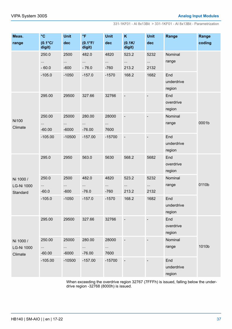
3.3.1.2.4 Measuring type Thermo resistance measuringMeasuring type coding: 1001b; wiring diagram (Conn.: 4, 5, 6)
Meas.range
°C(0.1°C/digit)
Unitdec
°F(0.1°F/digit)
Unitdec
K(0.1K/digit)
Unitdec
Range Rangecoding
Pt100
Standard
1000.0 10000 1832.0 18320 1273.2 12732 End
overdrive
region
0010b
850.0
...
-200.0
8500
...
-2000
1562
...
-328.0
15620
...
-3280
1123.2
...
73.2
11232
...
732
Nominal
range
-243.0 -2430 -405.4 -4054 30.2 302 End
underdrive
region
Pt100
Climate
155.00 15500 311.00 31100 - - End
overdrive
region
0000b
130.00
...
-120.00
13000
...
-12000
266.00
...
-184.00
26600
...
-18400
- - Nominal
range
-145.00 -14500 -229.00 -22900 - - End
underdrive
region
Ni100
Standard
295.0 2950 563.0 5630 568.2 5682 End
overdrive
region
0011b
VIPA System 300SAnalog Input Modules
331-1KF01 - AI 8x13Bit > 331-1KF01 - AI 8x13Bit - Parametrization
HB140 | SM-AIO | | en | 17-22 36
Meas.range
°C(0.1°C/digit)
Unitdec
°F(0.1°F/digit)
Unitdec
K(0.1K/digit)
Unitdec
Range Rangecoding
250.0
...
- 60.0
2500
...
-600
482.0
...
- 76.0
4820
...
-760
523.2
...
213.2
5232
...
2132
Nominal
range
-105.0 -1050 -157.0 -1570 168.2 1682 End
underdrive
region
Ni100
Climate
295.00 29500 327.66 32766 - - End
overdrive
region
0001b
250.00
...
-60.00
25000
...
-6000
280.00
...
-76.00
28000
...
7600
- - Nominal
range
-105.00 -10500 -157.00 -15700 - - End
underdrive
region
Ni 1000 /
LG-Ni 1000
Standard
295.0 2950 563.0 5630 568.2 5682 End
overdrive
region
0110b
250.0
...
-60.0
2500
...
-600
482.0
...
-76.0
4820
...
-760
523.2
...
213.2
5232
...
2132
Nominal
range
-105.0 -1050 -157.0 -1570 168.2 1682 End
underdrive
region
Ni 1000 /
LG-Ni 1000
Climate
295.00 29500 327.66 32766 - - End
overdrive
region
1010b
250.00
...
-60.00
25000
...
-6000
280.00
...
-76.00
28000
...
7600
- - Nominal
range
-105.00 -10500 -157.00 -15700 - - End
underdrive
region
When exceeding the overdrive region 32767 (7FFFh) is issued, falling below the under-drive region -32768 (8000h) is issued.
VIPA System 300S Analog Input Modules
331-1KF01 - AI 8x13Bit > 331-1KF01 - AI 8x13Bit - Parametrization
HB140 | SM-AIO | | en | 17-22 37
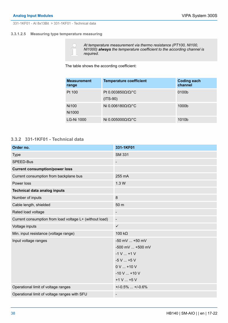
3.3.1.2.5 Measuring type temperature measuring
At temperature measurement via thermo resistance (PT100, NI100,NI1000) always the temperature coefficient to the according channel isrequired.
The table shows the according coefficient:
Measurementrange
Temperature coefficient Coding eachchannel
Pt 100 Pt 0.003850Ω/Ω/°C
(ITS-90)
0100b
Ni100
Ni1000
Ni 0.006180Ω/Ω/°C 1000b
LG-Ni 1000 Ni 0.005000Ω/Ω/°C 1010b
3.3.2 331-1KF01 - Technical dataOrder no. 331-1KF01
Type SM 331
SPEED-Bus -
Current consumption/power loss
Current consumption from backplane bus 255 mA
Power loss 1.3 W
Technical data analog inputs
Number of inputs 8
Cable length, shielded 50 m
Rated load voltage -
Current consumption from load voltage L+ (without load) -
Voltage inputs ü
Min. input resistance (voltage range) 100 kΩ
Input voltage ranges -50 mV ... +50 mV
-500 mV ... +500 mV
-1 V ... +1 V
-5 V ... +5 V
0 V ... +10 V
-10 V ... +10 V
+1 V ... +5 V
Operational limit of voltage ranges +/-0.5% ... +/-0.6%
Operational limit of voltage ranges with SFU -
VIPA System 300SAnalog Input Modules
331-1KF01 - AI 8x13Bit > 331-1KF01 - Technical data
HB140 | SM-AIO | | en | 17-22 38
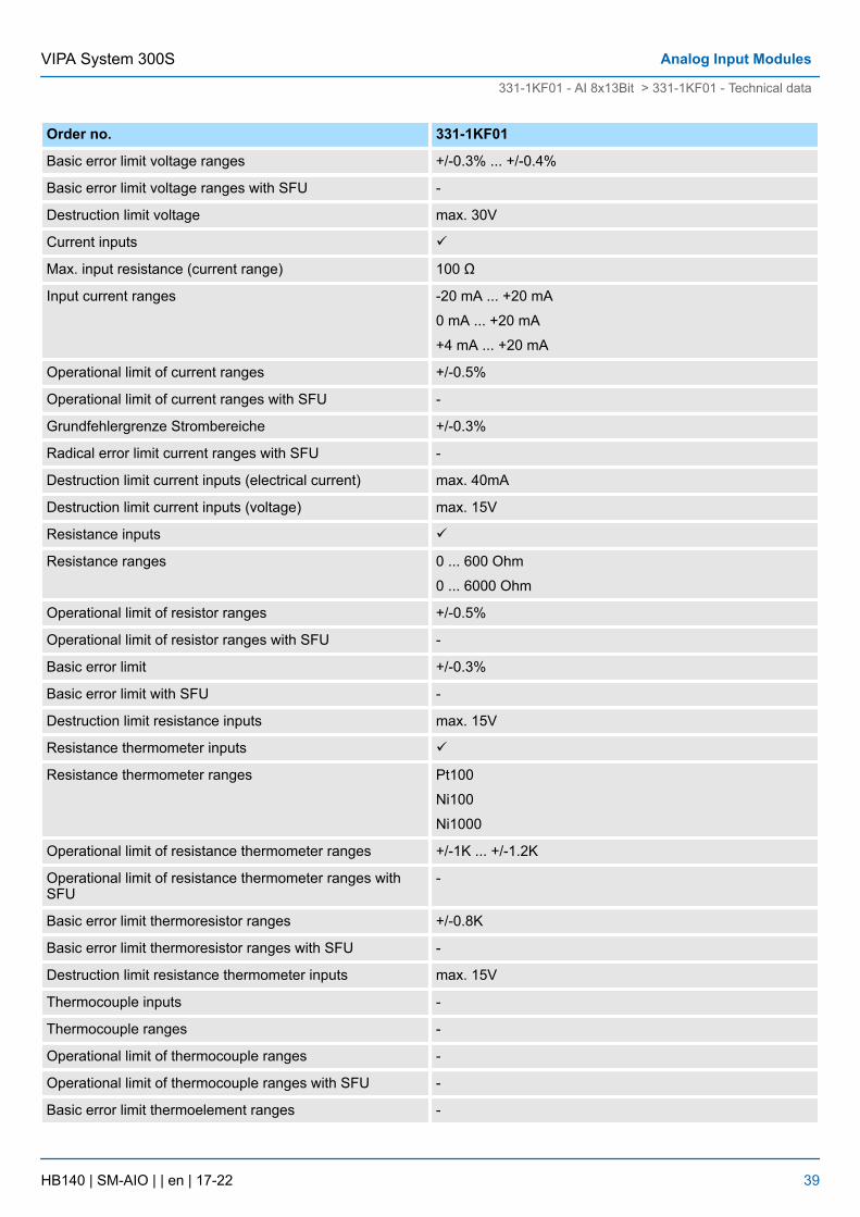
Order no. 331-1KF01
Basic error limit voltage ranges +/-0.3% ... +/-0.4%
Basic error limit voltage ranges with SFU -
Destruction limit voltage max. 30V
Current inputs ü
Max. input resistance (current range) 100 Ω
Input current ranges -20 mA ... +20 mA
0 mA ... +20 mA
+4 mA ... +20 mA
Operational limit of current ranges +/-0.5%
Operational limit of current ranges with SFU -
Grundfehlergrenze Strombereiche +/-0.3%
Radical error limit current ranges with SFU -
Destruction limit current inputs (electrical current) max. 40mA
Destruction limit current inputs (voltage) max. 15V
Resistance inputs ü
Resistance ranges 0 ... 600 Ohm
0 ... 6000 Ohm
Operational limit of resistor ranges +/-0.5%
Operational limit of resistor ranges with SFU -
Basic error limit +/-0.3%
Basic error limit with SFU -
Destruction limit resistance inputs max. 15V
Resistance thermometer inputs ü
Resistance thermometer ranges Pt100
Ni100
Ni1000
Operational limit of resistance thermometer ranges +/-1K ... +/-1.2K
Operational limit of resistance thermometer ranges withSFU
-
Basic error limit thermoresistor ranges +/-0.8K
Basic error limit thermoresistor ranges with SFU -
Destruction limit resistance thermometer inputs max. 15V
Thermocouple inputs -
Thermocouple ranges -
Operational limit of thermocouple ranges -
Operational limit of thermocouple ranges with SFU -
Basic error limit thermoelement ranges -
VIPA System 300S Analog Input Modules
331-1KF01 - AI 8x13Bit > 331-1KF01 - Technical data
HB140 | SM-AIO | | en | 17-22 39
Order no. 331-1KF01
Basic error limit thermoelement ranges with SFU -
Destruction limit thermocouple inputs -
Programmable temperature compensation -
External temperature compensation -
Internal temperature compensation -
Temperature error internal compensation -
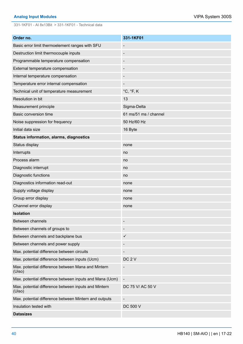
Technical unit of temperature measurement °C, °F, K
Resolution in bit 13
Measurement principle Sigma-Delta
Basic conversion time 61 ms/51 ms / channel
Noise suppression for frequency 50 Hz/60 Hz
Initial data size 16 Byte
Status information, alarms, diagnostics
Status display none
Interrupts no
Process alarm no
Diagnostic interrupt no
Diagnostic functions no
Diagnostics information read-out none
Supply voltage display none
Group error display none
Channel error display none
Isolation
Between channels -
Between channels of groups to -
Between channels and backplane bus ü
Between channels and power supply -
Max. potential difference between circuits -
Max. potential difference between inputs (Ucm) DC 2 V
Max. potential difference between Mana and Mintern(Uiso)
-
Max. potential difference between inputs and Mana (Ucm) -
Max. potential difference between inputs and Mintern(Uiso)
DC 75 V/ AC 50 V
Max. potential difference between Mintern and outputs -
Insulation tested with DC 500 V
Datasizes
VIPA System 300SAnalog Input Modules
331-1KF01 - AI 8x13Bit > 331-1KF01 - Technical data
HB140 | SM-AIO | | en | 17-22 40
Order no. 331-1KF01
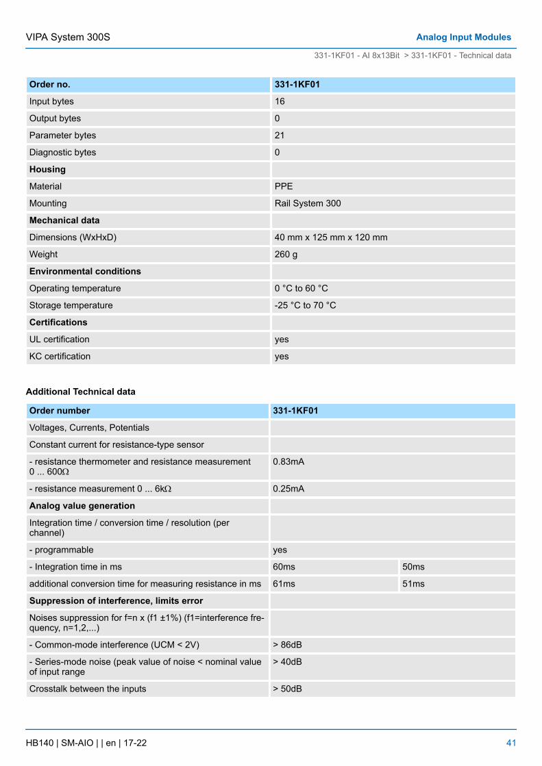
Input bytes 16
Output bytes 0
Parameter bytes 21
Diagnostic bytes 0
Housing
Material PPE
Mounting Rail System 300
Mechanical data
Dimensions (WxHxD) 40 mm x 125 mm x 120 mm
Weight 260 g
Environmental conditions
Operating temperature 0 °C to 60 °C
Storage temperature -25 °C to 70 °C
Certifications
UL certification yes
KC certification yes
Additional Technical data
Order number 331-1KF01
Voltages, Currents, Potentials
Constant current for resistance-type sensor
- resistance thermometer and resistance measurement0 ... 600W
0.83mA
- resistance measurement 0 ... 6kW 0.25mA
Analog value generation
Integration time / conversion time / resolution (perchannel)
- programmable yes
- Integration time in ms 60ms 50ms
additional conversion time for measuring resistance in ms 61ms 51ms
Suppression of interference, limits error
Noises suppression for f=n x (f1 ±1%) (f1=interference fre-quency, n=1,2,...)
- Common-mode interference (UCM < 2V) > 86dB
- Series-mode noise (peak value of noise < nominal valueof input range
> 40dB
Crosstalk between the inputs > 50dB
VIPA System 300S Analog Input Modules
331-1KF01 - AI 8x13Bit > 331-1KF01 - Technical data
HB140 | SM-AIO | | en | 17-22 41
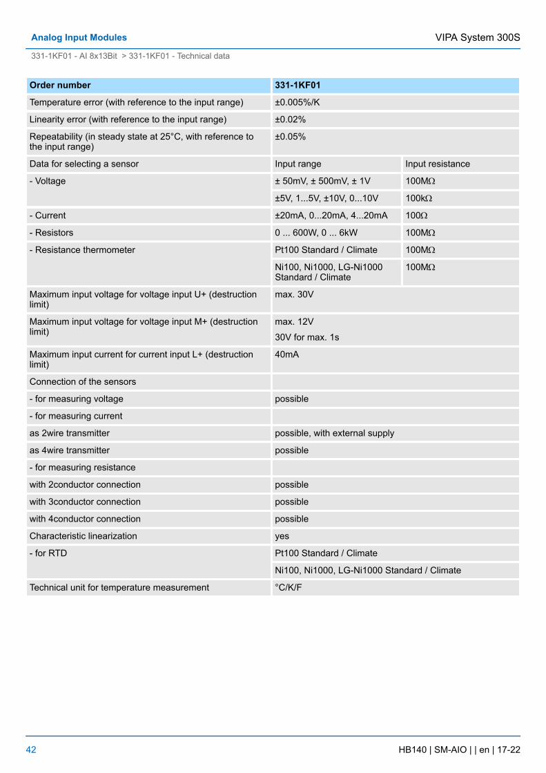
Order number 331-1KF01
Temperature error (with reference to the input range) ±0.005%/K
Linearity error (with reference to the input range) ±0.02%
Repeatability (in steady state at 25°C, with reference tothe input range)
±0.05%
Data for selecting a sensor Input range Input resistance
- Voltage ± 50mV, ± 500mV, ± 1V 100MW
±5V, 1...5V, ±10V, 0...10V 100kW
- Current ±20mA, 0...20mA, 4...20mA 100W
- Resistors 0 ... 600W, 0 ... 6kW 100MW
- Resistance thermometer Pt100 Standard / Climate 100MW
Ni100, Ni1000, LG-Ni1000Standard / Climate
100MW
Maximum input voltage for voltage input U+ (destructionlimit)
max. 30V
Maximum input voltage for voltage input M+ (destructionlimit)
max. 12V
30V for max. 1s
Maximum input current for current input L+ (destructionlimit)
40mA
Connection of the sensors
- for measuring voltage possible
- for measuring current
as 2wire transmitter possible, with external supply
as 4wire transmitter possible
- for measuring resistance
with 2conductor connection possible
with 3conductor connection possible
with 4conductor connection possible
Characteristic linearization yes
- for RTD Pt100 Standard / Climate
Ni100, Ni1000, LG-Ni1000 Standard / Climate
Technical unit for temperature measurement °C/K/F
VIPA System 300SAnalog Input Modules
331-1KF01 - AI 8x13Bit > 331-1KF01 - Technical data
HB140 | SM-AIO | | en | 17-22 42
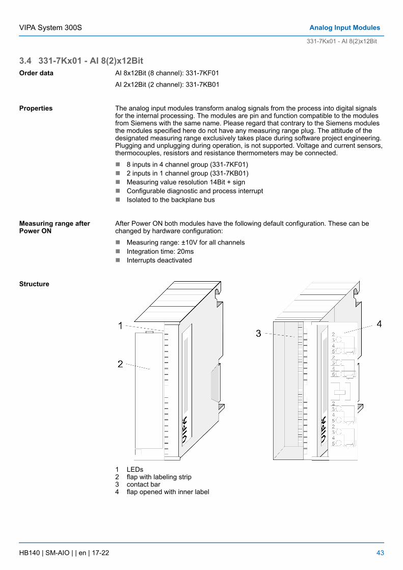
3.4 331-7Kx01 - AI 8(2)x12BitAI 8x12Bit (8 channel): 331-7KF01
AI 2x12Bit (2 channel): 331-7KB01
The analog input modules transform analog signals from the process into digital signalsfor the internal processing. The modules are pin and function compatible to the modulesfrom Siemens with the same name. Please regard that contrary to the Siemens modulesthe modules specified here do not have any measuring range plug. The attitude of thedesignated measuring range exclusively takes place during software project engineering.Plugging and unplugging during operation, is not supported. Voltage and current sensors,thermocouples, resistors and resistance thermometers may be connected.
n 8 inputs in 4 channel group (331-7KF01)n 2 inputs in 1 channel group (331-7KB01)n Measuring value resolution 14Bit + signn Configurable diagnostic and process interruptn Isolated to the backplane bus
After Power ON both modules have the following default configuration. These can bechanged by hardware configuration:
n Measuring range: ±10V for all channelsn Integration time: 20msn Interrupts deactivated
1 LEDs2 flap with labeling strip3 contact bar4 flap opened with inner label
Order data
Properties
Measuring range afterPower ON
Structure
VIPA System 300S Analog Input Modules
331-7Kx01 - AI 8(2)x12Bit
HB140 | SM-AIO | | en | 17-22 43
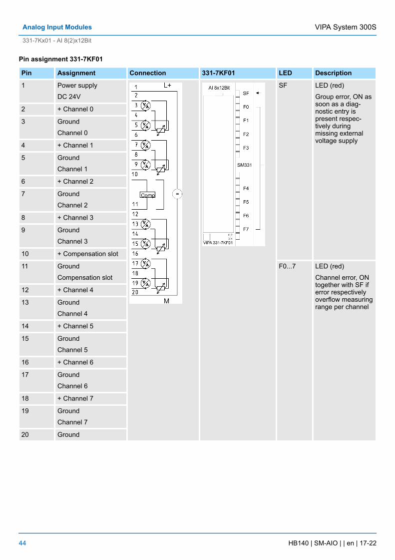
Pin assignment 331-7KF01
Pin Assignment Connection 331-7KF01 LED Description
1 Power supply
DC 24V
SF LED (red)
Group error, ON assoon as a diag-nostic entry ispresent respec-tively duringmissing externalvoltage supply
2 + Channel 0
3 Ground
Channel 0
4 + Channel 1
5 Ground
Channel 1
6 + Channel 2
7 Ground
Channel 2
8 + Channel 3
9 Ground
Channel 3
10 + Compensation slot
11 Ground
Compensation slot
F0...7 LED (red)
Channel error, ONtogether with SF iferror respectivelyoverflow measuringrange per channel
12 + Channel 4
13 Ground
Channel 4
14 + Channel 5
15 Ground
Channel 5
16 + Channel 6
17 Ground
Channel 6
18 + Channel 7
19 Ground
Channel 7
20 Ground
VIPA System 300SAnalog Input Modules
331-7Kx01 - AI 8(2)x12Bit
HB140 | SM-AIO | | en | 17-22 44
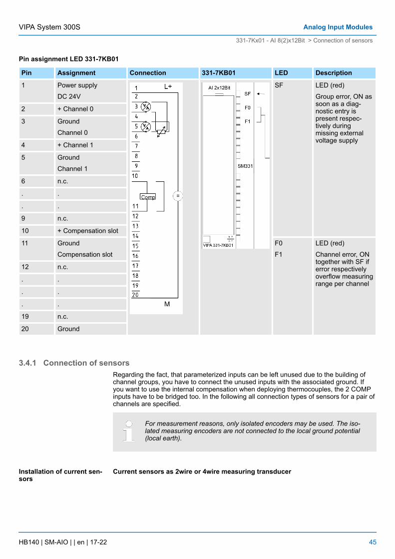
Pin assignment LED 331-7KB01
Pin Assignment Connection 331-7KB01 LED Description
1 Power supply
DC 24V
SF LED (red)
Group error, ON assoon as a diag-nostic entry ispresent respec-tively duringmissing externalvoltage supply
2 + Channel 0
3 Ground
Channel 0
4 + Channel 1
5 Ground
Channel 1
6 n.c.
. .
. .
9 n.c.
10 + Compensation slot
11 Ground
Compensation slot
F0
F1
LED (red)
Channel error, ONtogether with SF iferror respectivelyoverflow measuringrange per channel
12 n.c.
. .
. .
. .
19 n.c.
20 Ground
3.4.1 Connection of sensorsRegarding the fact, that parameterized inputs can be left unused due to the building ofchannel groups, you have to connect the unused inputs with the associated ground. Ifyou want to use the internal compensation when deploying thermocouples, the 2 COMPinputs have to be bridged too. In the following all connection types of sensors for a pair ofchannels are specified.
For measurement reasons, only isolated encoders may be used. The iso-lated measuring encoders are not connected to the local ground potential(local earth).
Current sensors as 2wire or 4wire measuring transducerInstallation of current sen-sors
VIPA System 300S Analog Input Modules
331-7Kx01 - AI 8(2)x12Bit > Connection of sensors
HB140 | SM-AIO | | en | 17-22 45
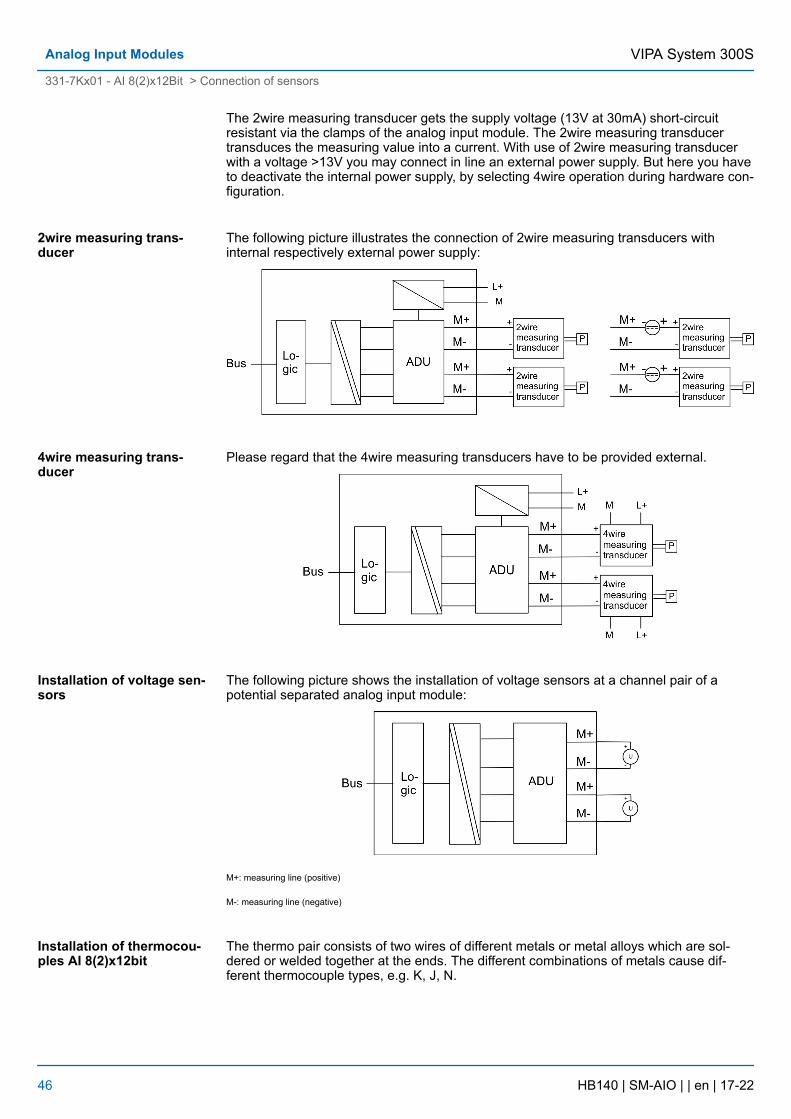
The 2wire measuring transducer gets the supply voltage (13V at 30mA) short-circuitresistant via the clamps of the analog input module. The 2wire measuring transducertransduces the measuring value into a current. With use of 2wire measuring transducerwith a voltage >13V you may connect in line an external power supply. But here you haveto deactivate the internal power supply, by selecting 4wire operation during hardware con-figuration.
The following picture illustrates the connection of 2wire measuring transducers withinternal respectively external power supply:
Please regard that the 4wire measuring transducers have to be provided external.
The following picture shows the installation of voltage sensors at a channel pair of apotential separated analog input module:
M+: measuring line (positive)
M-: measuring line (negative)
The thermo pair consists of two wires of different metals or metal alloys which are sol-dered or welded together at the ends. The different combinations of metals cause dif-ferent thermocouple types, e.g. K, J, N.
2wire measuring trans-ducer
4wire measuring trans-ducer
Installation of voltage sen-sors
Installation of thermocou-ples AI 8(2)x12bit
VIPA System 300SAnalog Input Modules
331-7Kx01 - AI 8(2)x12Bit > Connection of sensors
HB140 | SM-AIO | | en | 17-22 46
Independent from the type of the thermocouple the principle of measuring is identical forall types: When the measuring point has another temperature than the free ends of thethermo pair (connection point), a voltage occurs between the free ends, the thermovoltage. The amount of the thermo voltage depends on the difference between the tem-perature at the measuring point and the temperature at the free ends. For a thermo pairalways records a temperature difference, the free ends have to be set on a comparisonpoint with known temperature, to determine the temperature at the measuring point.
The thermo pairs may be extended from your connecting point to a point with known tem-perature (comparison point) via compensating lines. The compensating lines have thesame material as the wires of the thermocouple. The leads are out of copper. In this caseyou should use the external compensation. Please regard pole correct installation, for thismay cause enormous measuring errors.
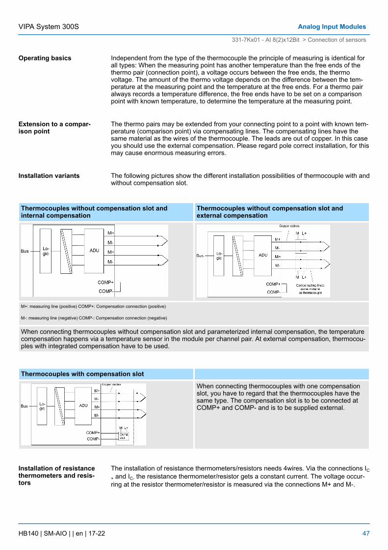
The following pictures show the different installation possibilities of thermocouple with andwithout compensation slot.
Thermocouples without compensation slot andinternal compensation
Thermocouples without compensation slot andexternal compensation
M+: measuring line (positive) COMP+: Compensation connection (positive)
M-: measuring line (negative) COMP-: Compensation connection (negative)
When connecting thermocouples without compensation slot and parameterized internal compensation, the temperaturecompensation happens via a temperature sensor in the module per channel pair. At external compensation, thermocou-ples with integrated compensation have to be used.
Thermocouples with compensation slot
When connecting thermocouples with one compensationslot, you have to regard that the thermocouples have thesame type. The compensation slot is to be connected atCOMP+ and COMP- and is to be supplied external.
The installation of resistance thermometers/resistors needs 4wires. Via the connections IC+ and IC- the resistance thermometer/resistor gets a constant current. The voltage occur-ring at the resistor thermometer/resistor is measured via the connections M+ and M-.
Operating basics
Extension to a compar-ison point
Installation variants
Installation of resistancethermometers and resis-tors
VIPA System 300S Analog Input Modules
331-7Kx01 - AI 8(2)x12Bit > Connection of sensors
HB140 | SM-AIO | | en | 17-22 47
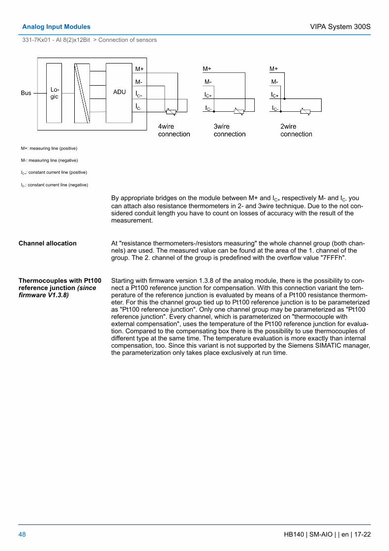
M+: measuring line (positive)
M-: measuring line (negative)
IC+: constant current line (positive)
IC-: constant current line (negative)
By appropriate bridges on the module between M+ and IC+ respectively M- and IC- youcan attach also resistance thermometers in 2- and 3wire technique. Due to the not con-sidered conduit length you have to count on losses of accuracy with the result of themeasurement.
At "resistance thermometers-/resistors measuring" the whole channel group (both chan-nels) are used. The measured value can be found at the area of the 1. channel of thegroup. The 2. channel of the group is predefined with the overflow value "7FFFh".
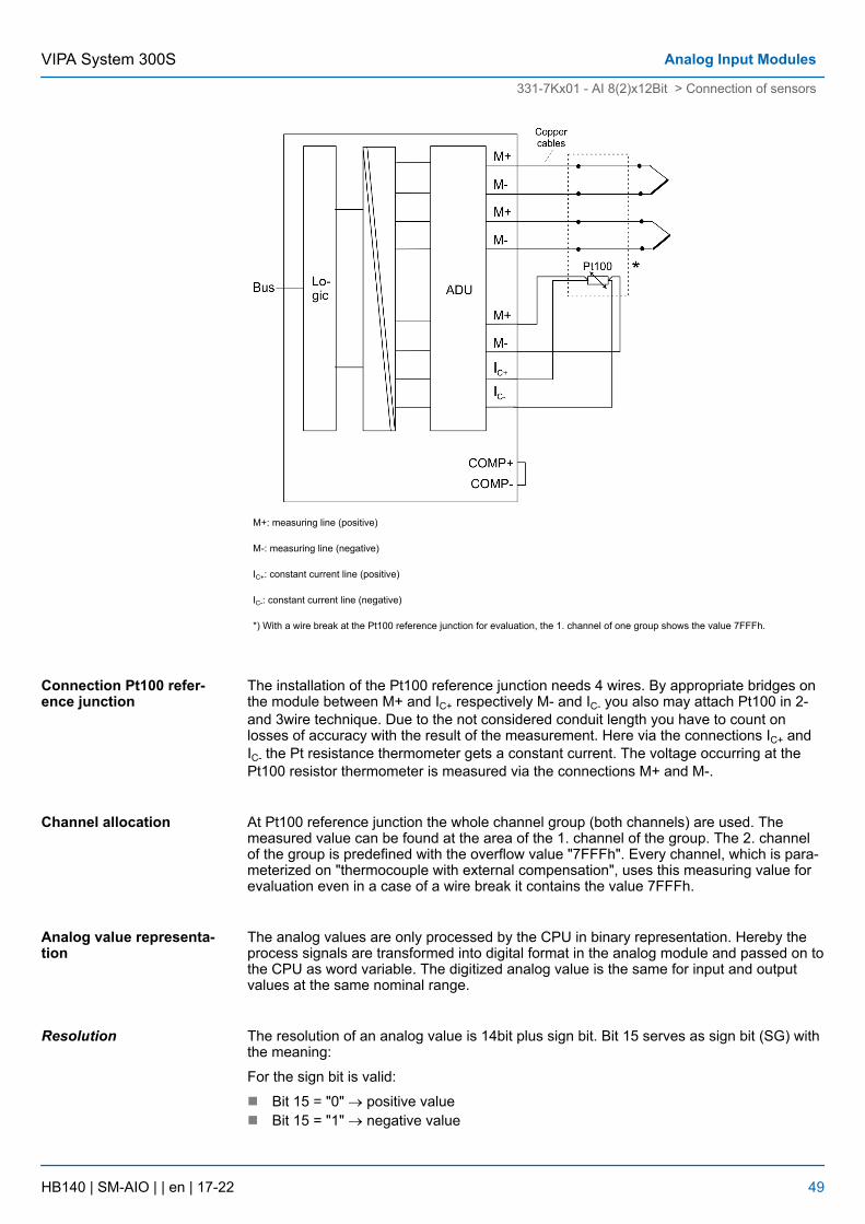
Starting with firmware version 1.3.8 of the analog module, there is the possibility to con-nect a Pt100 reference junction for compensation. With this connection variant the tem-perature of the reference junction is evaluated by means of a Pt100 resistance thermom-eter. For this the channel group tied up to Pt100 reference junction is to be parameterizedas "Pt100 reference junction". Only one channel group may be parameterized as "Pt100reference junction". Every channel, which is parameterized on "thermocouple withexternal compensation", uses the temperature of the Pt100 reference junction for evalua-tion. Compared to the compensating box there is the possibility to use thermocouples ofdifferent type at the same time. The temperature evaluation is more exactly than internalcompensation, too. Since this variant is not supported by the Siemens SIMATIC manager,the parameterization only takes place exclusively at run time.
Channel allocation
Thermocouples with Pt100reference junction (sincefirmware V1.3.8)
VIPA System 300SAnalog Input Modules
331-7Kx01 - AI 8(2)x12Bit > Connection of sensors
HB140 | SM-AIO | | en | 17-22 48
M+: measuring line (positive)
M-: measuring line (negative)
IC+: constant current line (positive)
IC-: constant current line (negative)
*) With a wire break at the Pt100 reference junction for evaluation, the 1. channel of one group shows the value 7FFFh.
The installation of the Pt100 reference junction needs 4 wires. By appropriate bridges onthe module between M+ and IC+ respectively M- and IC- you also may attach Pt100 in 2-and 3wire technique. Due to the not considered conduit length you have to count onlosses of accuracy with the result of the measurement. Here via the connections IC+ andIC- the Pt resistance thermometer gets a constant current. The voltage occurring at thePt100 resistor thermometer is measured via the connections M+ and M-.
At Pt100 reference junction the whole channel group (both channels) are used. Themeasured value can be found at the area of the 1. channel of the group. The 2. channelof the group is predefined with the overflow value "7FFFh". Every channel, which is para-meterized on "thermocouple with external compensation", uses this measuring value forevaluation even in a case of a wire break it contains the value 7FFFh.
The analog values are only processed by the CPU in binary representation. Hereby theprocess signals are transformed into digital format in the analog module and passed on tothe CPU as word variable. The digitized analog value is the same for input and outputvalues at the same nominal range.
The resolution of an analog value is 14bit plus sign bit. Bit 15 serves as sign bit (SG) withthe meaning:
For the sign bit is valid:
n Bit 15 = "0" ® positive valuen Bit 15 = "1" ® negative value
Connection Pt100 refer-ence junction
Channel allocation
Analog value representa-tion
Resolution
VIPA System 300S Analog Input Modules
331-7Kx01 - AI 8(2)x12Bit > Connection of sensors
HB140 | SM-AIO | | en | 17-22 49
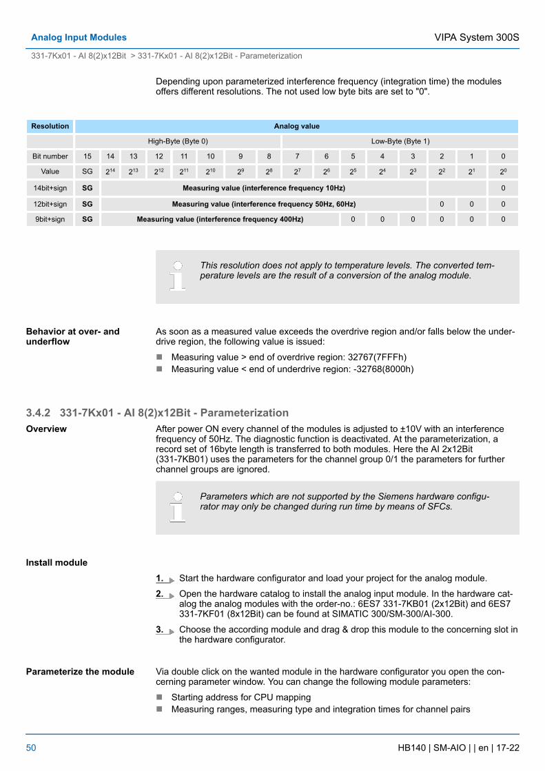
Depending upon parameterized interference frequency (integration time) the modulesoffers different resolutions. The not used low byte bits are set to "0".
Resolution Analog value
High-Byte (Byte 0) Low-Byte (Byte 1)
Bit number 15 14 13 12 11 10 9 8 7 6 5 4 3 2 1 0
Value SG 214 213 212 211 210 29 28 27 26 25 24 23 22 21 20
14bit+sign SG Measuring value (interference frequency 10Hz) 0
12bit+sign SG Measuring value (interference frequency 50Hz, 60Hz) 0 0 0
9bit+sign SG Measuring value (interference frequency 400Hz) 0 0 0 0 0 0
This resolution does not apply to temperature levels. The converted tem-perature levels are the result of a conversion of the analog module.
As soon as a measured value exceeds the overdrive region and/or falls below the under-drive region, the following value is issued:
n Measuring value > end of overdrive region: 32767(7FFFh)n Measuring value < end of underdrive region: -32768(8000h)
3.4.2 331-7Kx01 - AI 8(2)x12Bit - ParameterizationAfter power ON every channel of the modules is adjusted to ±10V with an interferencefrequency of 50Hz. The diagnostic function is deactivated. At the parameterization, arecord set of 16byte length is transferred to both modules. Here the AI 2x12Bit(331-7KB01) uses the parameters for the channel group 0/1 the parameters for furtherchannel groups are ignored.
Parameters which are not supported by the Siemens hardware configu-rator may only be changed during run time by means of SFCs.
1. Start the hardware configurator and load your project for the analog module.
2. Open the hardware catalog to install the analog input module. In the hardware cat-alog the analog modules with the order-no.: 6ES7 331-7KB01 (2x12Bit) and 6ES7331-7KF01 (8x12Bit) can be found at SIMATIC 300/SM-300/AI-300.
3. Choose the according module and drag & drop this module to the concerning slot inthe hardware configurator.
Via double click on the wanted module in the hardware configurator you open the con-cerning parameter window. You can change the following module parameters:
n Starting address for CPU mappingn Measuring ranges, measuring type and integration times for channel pairs
Behavior at over- andunderflow
Overview
Install module
Parameterize the module
VIPA System 300SAnalog Input Modules
331-7Kx01 - AI 8(2)x12Bit > 331-7Kx01 - AI 8(2)x12Bit - Parameterization
HB140 | SM-AIO | | en | 17-22 50
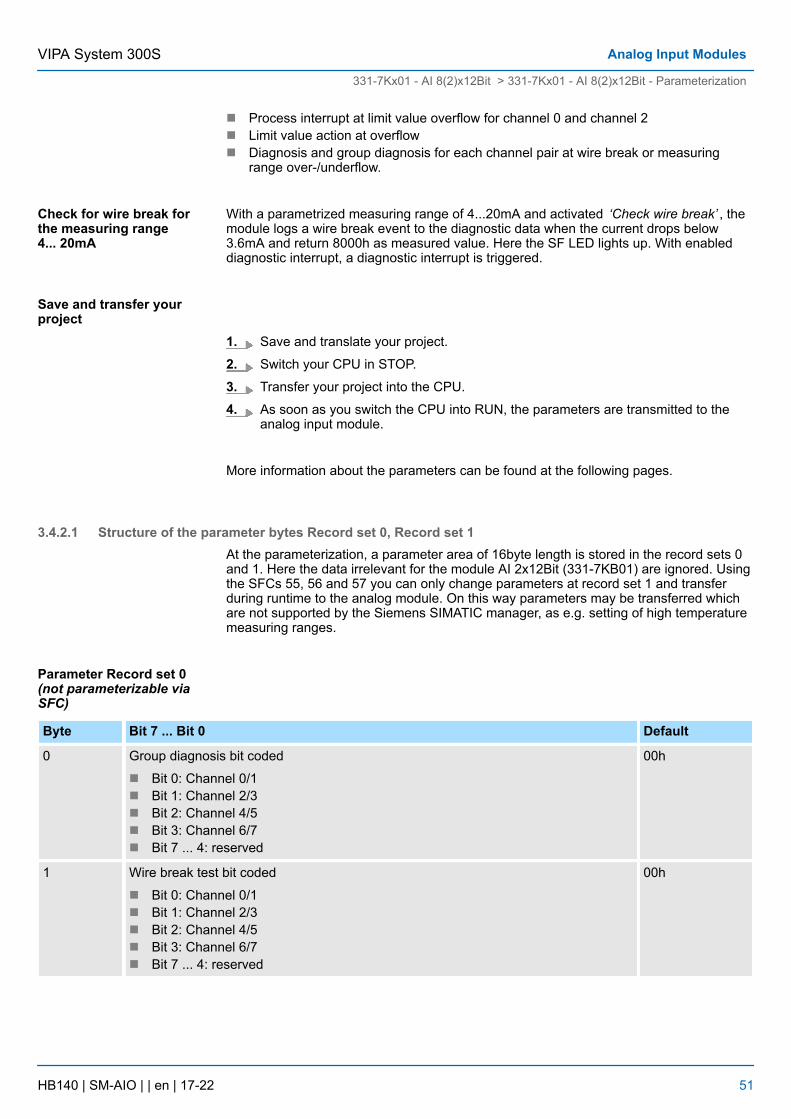
n Process interrupt at limit value overflow for channel 0 and channel 2n Limit value action at overflown Diagnosis and group diagnosis for each channel pair at wire break or measuring
range over-/underflow.
With a parametrized measuring range of 4...20mA and activated ‘Check wire break’ , themodule logs a wire break event to the diagnostic data when the current drops below3.6mA and return 8000h as measured value. Here the SF LED lights up. With enableddiagnostic interrupt, a diagnostic interrupt is triggered.
1. Save and translate your project.
2. Switch your CPU in STOP.
3. Transfer your project into the CPU.
4. As soon as you switch the CPU into RUN, the parameters are transmitted to theanalog input module.
More information about the parameters can be found at the following pages.
3.4.2.1 Structure of the parameter bytes Record set 0, Record set 1At the parameterization, a parameter area of 16byte length is stored in the record sets 0and 1. Here the data irrelevant for the module AI 2x12Bit (331-7KB01) are ignored. Usingthe SFCs 55, 56 and 57 you can only change parameters at record set 1 and transferduring runtime to the analog module. On this way parameters may be transferred whichare not supported by the Siemens SIMATIC manager, as e.g. setting of high temperaturemeasuring ranges.
Byte Bit 7 ... Bit 0 Default
0 Group diagnosis bit coded
n Bit 0: Channel 0/1n Bit 1: Channel 2/3n Bit 2: Channel 4/5n Bit 3: Channel 6/7n Bit 7 ... 4: reserved
00h
1 Wire break test bit coded
n Bit 0: Channel 0/1n Bit 1: Channel 2/3n Bit 2: Channel 4/5n Bit 3: Channel 6/7n Bit 7 ... 4: reserved
00h
Check for wire break forthe measuring range4... 20mA
Save and transfer yourproject
Parameter Record set 0(not parameterizable viaSFC)
VIPA System 300S Analog Input Modules
331-7Kx01 - AI 8(2)x12Bit > 331-7Kx01 - AI 8(2)x12Bit - Parameterization
HB140 | SM-AIO | | en | 17-22 51
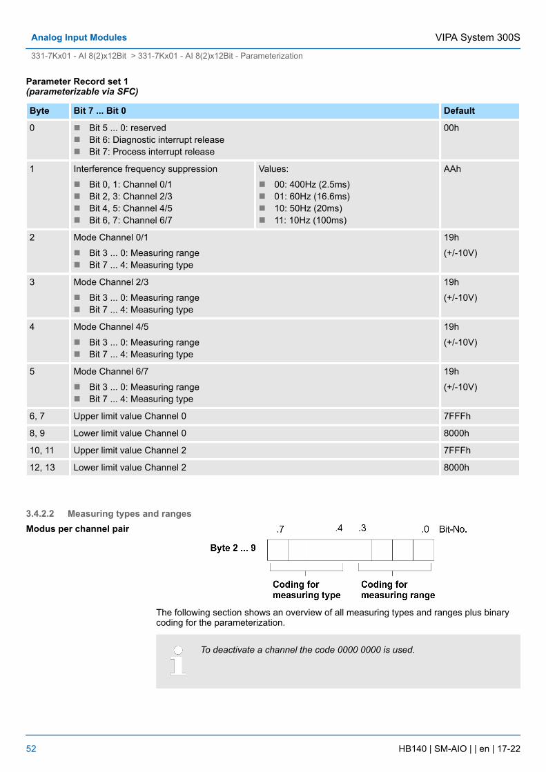
Byte Bit 7 ... Bit 0 Default
0 n Bit 5 ... 0: reservedn Bit 6: Diagnostic interrupt releasen Bit 7: Process interrupt release
00h
1 Interference frequency suppression
n Bit 0, 1: Channel 0/1n Bit 2, 3: Channel 2/3n Bit 4, 5: Channel 4/5n Bit 6, 7: Channel 6/7
Values:
n 00: 400Hz (2.5ms)n 01: 60Hz (16.6ms)n 10: 50Hz (20ms)n 11: 10Hz (100ms)
AAh
2 Mode Channel 0/1
n Bit 3 ... 0: Measuring rangen Bit 7 ... 4: Measuring type
19h
(+/-10V)
3 Mode Channel 2/3
n Bit 3 ... 0: Measuring rangen Bit 7 ... 4: Measuring type
19h
(+/-10V)
4 Mode Channel 4/5
n Bit 3 ... 0: Measuring rangen Bit 7 ... 4: Measuring type
19h
(+/-10V)
5 Mode Channel 6/7
n Bit 3 ... 0: Measuring rangen Bit 7 ... 4: Measuring type
19h
(+/-10V)
6, 7 Upper limit value Channel 0 7FFFh
8, 9 Lower limit value Channel 0 8000h
10, 11 Upper limit value Channel 2 7FFFh
12, 13 Lower limit value Channel 2 8000h
3.4.2.2 Measuring types and ranges
The following section shows an overview of all measuring types and ranges plus binarycoding for the parameterization.
To deactivate a channel the code 0000 0000 is used.
Parameter Record set 1(parameterizable via SFC)
Modus per channel pair
VIPA System 300SAnalog Input Modules
331-7Kx01 - AI 8(2)x12Bit > 331-7Kx01 - AI 8(2)x12Bit - Parameterization
HB140 | SM-AIO | | en | 17-22 52
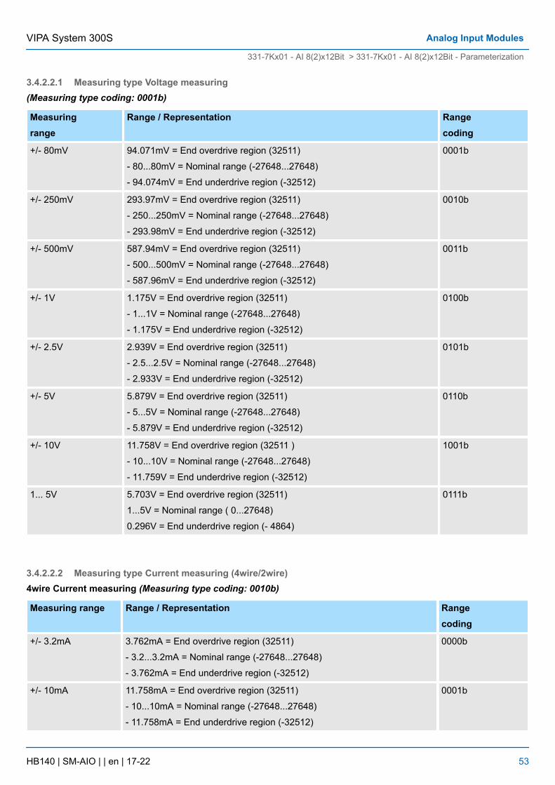
3.4.2.2.1 Measuring type Voltage measuring(Measuring type coding: 0001b)
Measuringrange
Range / Representation Rangecoding
+/- 80mV 94.071mV = End overdrive region (32511)
- 80...80mV = Nominal range (-27648...27648)
- 94.074mV = End underdrive region (-32512)
0001b
+/- 250mV 293.97mV = End overdrive region (32511)
- 250...250mV = Nominal range (-27648...27648)
- 293.98mV = End underdrive region (-32512)
0010b
+/- 500mV 587.94mV = End overdrive region (32511)
- 500...500mV = Nominal range (-27648...27648)
- 587.96mV = End underdrive region (-32512)
0011b
+/- 1V 1.175V = End overdrive region (32511)
- 1...1V = Nominal range (-27648...27648)
- 1.175V = End underdrive region (-32512)
0100b
+/- 2.5V 2.939V = End overdrive region (32511)
- 2.5...2.5V = Nominal range (-27648...27648)
- 2.933V = End underdrive region (-32512)
0101b
+/- 5V 5.879V = End overdrive region (32511)
- 5...5V = Nominal range (-27648...27648)
- 5.879V = End underdrive region (-32512)
0110b
+/- 10V 11.758V = End overdrive region (32511 )
- 10...10V = Nominal range (-27648...27648)
- 11.759V = End underdrive region (-32512)
1001b
1... 5V 5.703V = End overdrive region (32511)
1...5V = Nominal range ( 0...27648)
0.296V = End underdrive region (- 4864)
0111b
3.4.2.2.2 Measuring type Current measuring (4wire/2wire)4wire Current measuring (Measuring type coding: 0010b)
Measuring range Range / Representation Rangecoding
+/- 3.2mA 3.762mA = End overdrive region (32511)
- 3.2...3.2mA = Nominal range (-27648...27648)
- 3.762mA = End underdrive region (-32512)
0000b
+/- 10mA 11.758mA = End overdrive region (32511)
- 10...10mA = Nominal range (-27648...27648)
- 11.758mA = End underdrive region (-32512)
0001b
VIPA System 300S Analog Input Modules
331-7Kx01 - AI 8(2)x12Bit > 331-7Kx01 - AI 8(2)x12Bit - Parameterization
HB140 | SM-AIO | | en | 17-22 53
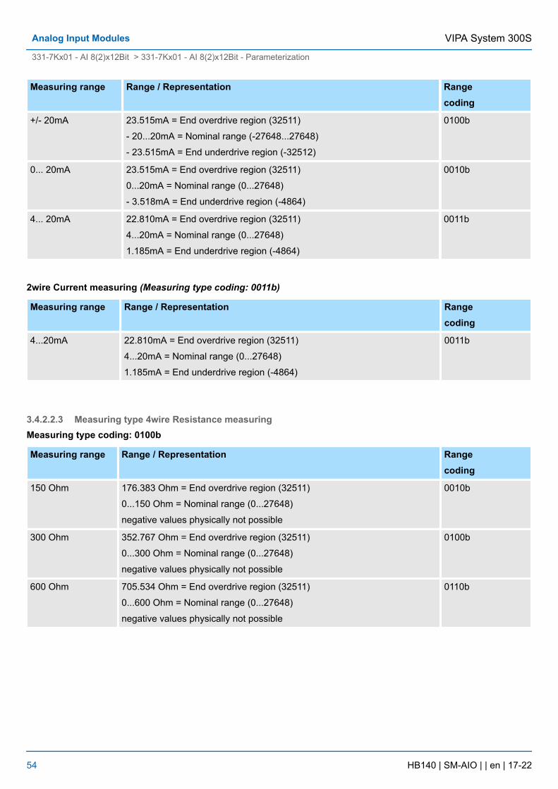
Measuring range Range / Representation Rangecoding
+/- 20mA 23.515mA = End overdrive region (32511)
- 20...20mA = Nominal range (-27648...27648)
- 23.515mA = End underdrive region (-32512)
0100b
0... 20mA 23.515mA = End overdrive region (32511)
0...20mA = Nominal range (0...27648)
- 3.518mA = End underdrive region (-4864)
0010b
4... 20mA 22.810mA = End overdrive region (32511)
4...20mA = Nominal range (0...27648)
1.185mA = End underdrive region (-4864)
0011b
2wire Current measuring (Measuring type coding: 0011b)
Measuring range Range / Representation Rangecoding
4...20mA 22.810mA = End overdrive region (32511)
4...20mA = Nominal range (0...27648)
1.185mA = End underdrive region (-4864)
0011b
3.4.2.2.3 Measuring type 4wire Resistance measuringMeasuring type coding: 0100b
Measuring range Range / Representation Rangecoding
150 Ohm 176.383 Ohm = End overdrive region (32511)
0...150 Ohm = Nominal range (0...27648)
negative values physically not possible
0010b
300 Ohm 352.767 Ohm = End overdrive region (32511)
0...300 Ohm = Nominal range (0...27648)
negative values physically not possible
0100b
600 Ohm 705.534 Ohm = End overdrive region (32511)
0...600 Ohm = Nominal range (0...27648)
negative values physically not possible
0110b
VIPA System 300SAnalog Input Modules
331-7Kx01 - AI 8(2)x12Bit > 331-7Kx01 - AI 8(2)x12Bit - Parameterization
HB140 | SM-AIO | | en | 17-22 54
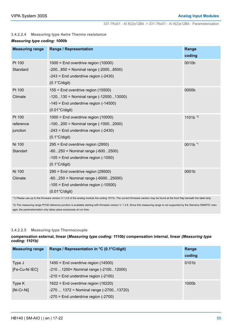
3.4.2.2.4 Measuring type 4wire Thermo resistanceMeasuring type coding: 1000b
Measuring range Range / Representation Rangecoding
Pt 100
Standard
1000 = End overdrive region (10000)
-200...850 = Nominal range (-2000...8500)
-243 = End underdrive region (-2430)
(0.1°C/digit)
0010b
Pt 100
Climate
155 = End overdrive region (15500)
-120...130 = Nominal range (-12000...13000)
-145 = End underdrive region (-14500)
(0.01°C/digit)
0000b
Pt 100
reference
junction
1000 = End overdrive region (10000)
-100...200 = Nominal range (-1000...2000)
-243 = End underdrive region (-2430)
(0.1°C/digit)
1101b *2
Ni 100
Standart
295 = End overdrive region (2950)
-60...250 = Nominal range (-600...2500)
-105 = End underdrive region (-1050)
(0.1°C/digit)
0011b *1
Ni 100
Climate
295 = End overdrive region (29500)
-60...250 = Nominal range (-6000...25000)
-105 = End underdrive region (-10500)
(0.01°C/digit)
0001b
*1) Please use up to the firmware version V.1.2.6 of the analog module the coding 1011b. The current firmware version may be found at the front flap beneath the label strip.
*2) The measuring range Pt100 reference junction is available starting with firmware version V. 1.3.8. Since this measuring range is not supported by the Siemens SIMATIC man-
ager, the parameterization only takes place exclusively at run time.
3.4.2.2.5 Measuring type Thermocouplecompensation external, linear (Measuring type coding: 1110b) compensation internal, linear (Measuring typecoding: 1101b)
Measuring range Range / Representation in °C (0.1°C/digit) Rangecoding
Type J
[Fe-Cu-Ni IEC]
1450 = End overdrive region (14500)
-210 ...1200= Nominal range (-2100...12000)
-210 = End underdrive region (-2100)
0101b
Type K
[Ni-Cr-Ni]
1622 = End overdrive region (16220)
-270 ... 1372 = Nominal range (-2700...13720)
-270 = End underdrive region (-2700)
1000b
VIPA System 300S Analog Input Modules
331-7Kx01 - AI 8(2)x12Bit > 331-7Kx01 - AI 8(2)x12Bit - Parameterization
HB140 | SM-AIO | | en | 17-22 55
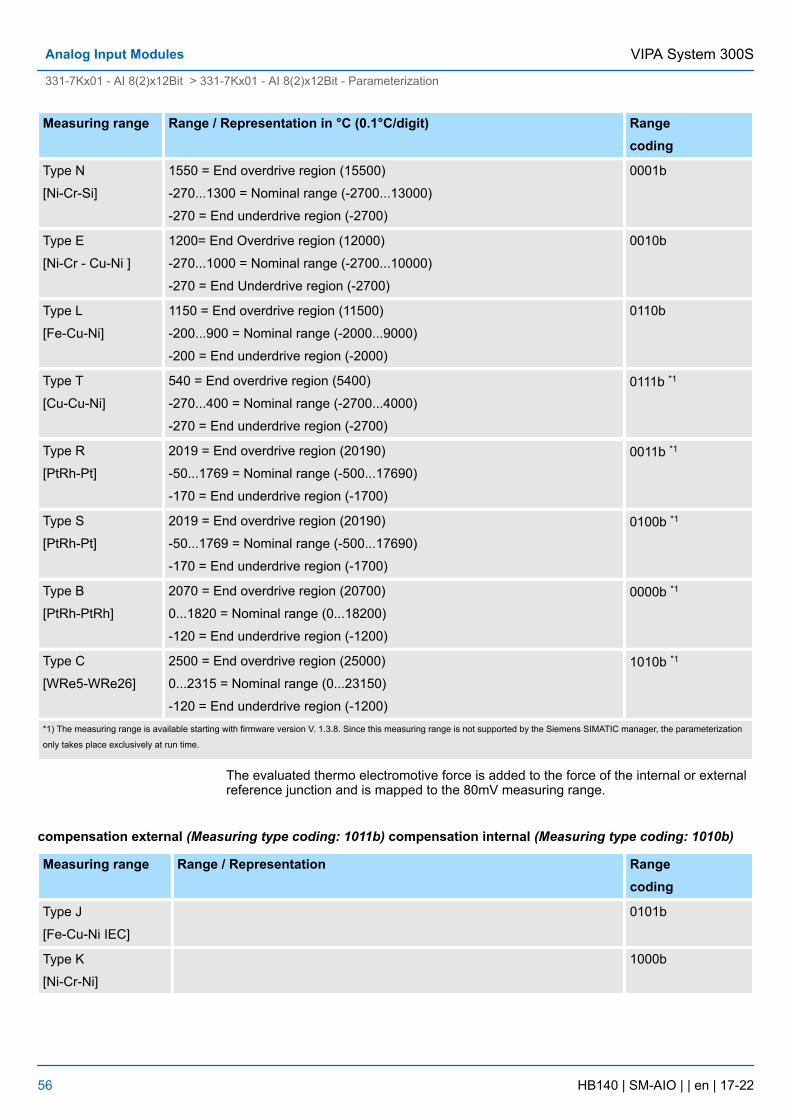
Measuring range Range / Representation in °C (0.1°C/digit) Rangecoding
Type N
[Ni-Cr-Si]
1550 = End overdrive region (15500)
-270...1300 = Nominal range (-2700...13000)
-270 = End underdrive region (-2700)
0001b
Type E
[Ni-Cr - Cu-Ni ]
1200= End Overdrive region (12000)
-270...1000 = Nominal range (-2700...10000)
-270 = End Underdrive region (-2700)
0010b
Type L
[Fe-Cu-Ni]
1150 = End overdrive region (11500)
-200...900 = Nominal range (-2000...9000)
-200 = End underdrive region (-2000)
0110b
Type T
[Cu-Cu-Ni]
540 = End overdrive region (5400)
-270...400 = Nominal range (-2700...4000)
-270 = End underdrive region (-2700)
0111b *1
Type R
[PtRh-Pt]
2019 = End overdrive region (20190)
-50...1769 = Nominal range (-500...17690)
-170 = End underdrive region (-1700)
0011b *1
Type S
[PtRh-Pt]
2019 = End overdrive region (20190)
-50...1769 = Nominal range (-500...17690)
-170 = End underdrive region (-1700)
0100b *1
Type B
[PtRh-PtRh]
2070 = End overdrive region (20700)
0...1820 = Nominal range (0...18200)
-120 = End underdrive region (-1200)
0000b *1
Type C
[WRe5-WRe26]
2500 = End overdrive region (25000)
0...2315 = Nominal range (0...23150)
-120 = End underdrive region (-1200)
1010b *1
*1) The measuring range is available starting with firmware version V. 1.3.8. Since this measuring range is not supported by the Siemens SIMATIC manager, the parameterization
only takes place exclusively at run time.
The evaluated thermo electromotive force is added to the force of the internal or externalreference junction and is mapped to the 80mV measuring range.
compensation external (Measuring type coding: 1011b) compensation internal (Measuring type coding: 1010b)
Measuring range Range / Representation Rangecoding
Type J
[Fe-Cu-Ni IEC]
0101b
Type K
[Ni-Cr-Ni]
1000b
VIPA System 300SAnalog Input Modules
331-7Kx01 - AI 8(2)x12Bit > 331-7Kx01 - AI 8(2)x12Bit - Parameterization
HB140 | SM-AIO | | en | 17-22 56
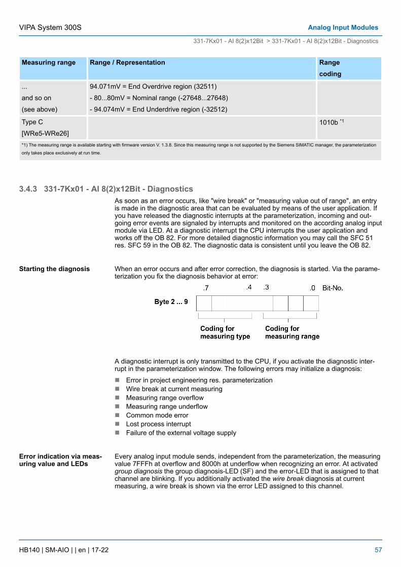
Measuring range Range / Representation Rangecoding
...
and so on
(see above)
94.071mV = End Overdrive region (32511)
- 80...80mV = Nominal range (-27648...27648)
- 94.074mV = End Underdrive region (-32512)
Type C
[WRe5-WRe26]1010b *1
*1) The measuring range is available starting with firmware version V. 1.3.8. Since this measuring range is not supported by the Siemens SIMATIC manager, the parameterization
only takes place exclusively at run time.
3.4.3 331-7Kx01 - AI 8(2)x12Bit - DiagnosticsAs soon as an error occurs, like "wire break" or "measuring value out of range", an entryis made in the diagnostic area that can be evaluated by means of the user application. Ifyou have released the diagnostic interrupts at the parameterization, incoming and out-going error events are signaled by interrupts and monitored on the according analog inputmodule via LED. At a diagnostic interrupt the CPU interrupts the user application andworks off the OB 82. For more detailed diagnostic information you may call the SFC 51res. SFC 59 in the OB 82. The diagnostic data is consistent until you leave the OB 82.
When an error occurs and after error correction, the diagnosis is started. Via the parame-terization you fix the diagnosis behavior at error:
A diagnostic interrupt is only transmitted to the CPU, if you activate the diagnostic inter-rupt in the parameterization window. The following errors may initialize a diagnosis:
n Error in project engineering res. parameterizationn Wire break at current measuringn Measuring range overflown Measuring range underflown Common mode errorn Lost process interruptn Failure of the external voltage supply
Every analog input module sends, independent from the parameterization, the measuringvalue 7FFFh at overflow and 8000h at underflow when recognizing an error. At activatedgroup diagnosis the group diagnosis-LED (SF) and the error-LED that is assigned to thatchannel are blinking. If you additionally activated the wire break diagnosis at currentmeasuring, a wire break is shown via the error LED assigned to this channel.
Starting the diagnosis
Error indication via meas-uring value and LEDs
VIPA System 300S Analog Input Modules
331-7Kx01 - AI 8(2)x12Bit > 331-7Kx01 - AI 8(2)x12Bit - Diagnostics
HB140 | SM-AIO | | en | 17-22 57
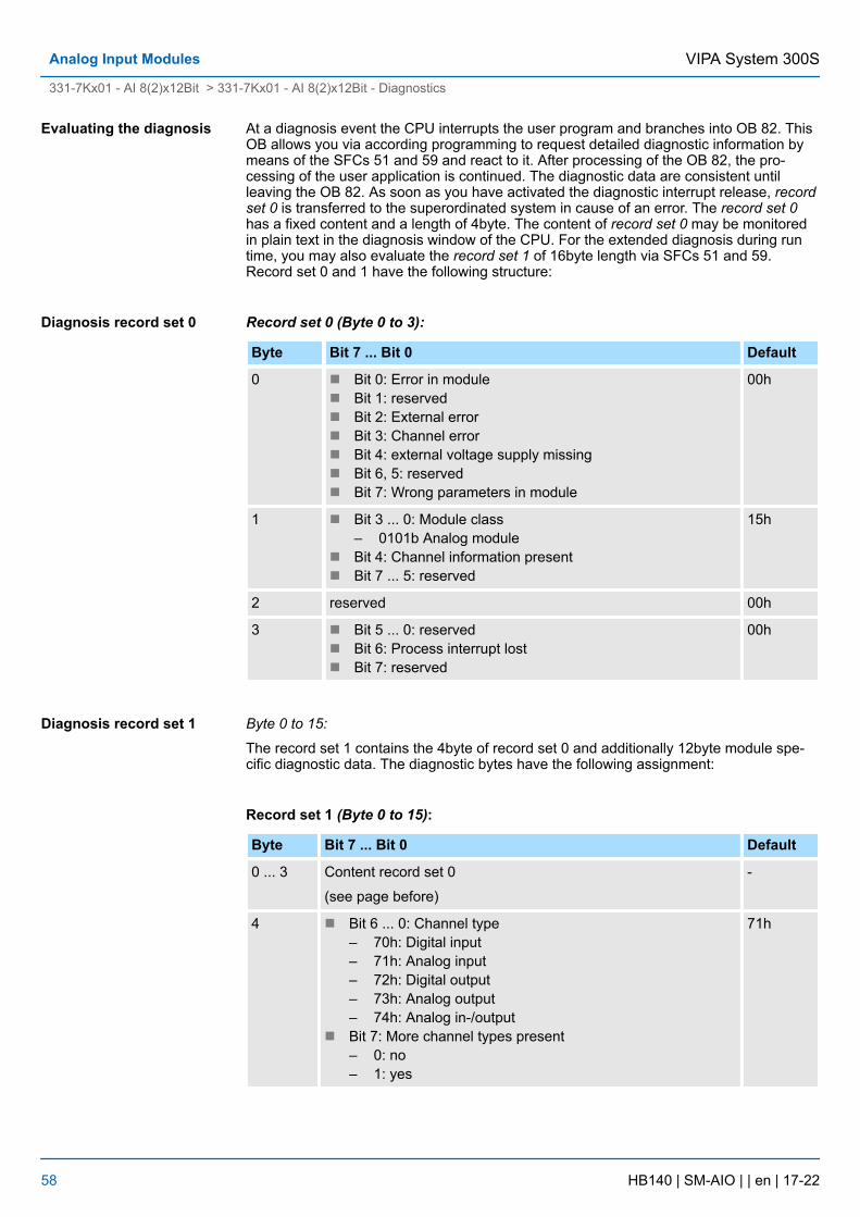
At a diagnosis event the CPU interrupts the user program and branches into OB 82. ThisOB allows you via according programming to request detailed diagnostic information bymeans of the SFCs 51 and 59 and react to it. After processing of the OB 82, the pro-cessing of the user application is continued. The diagnostic data are consistent untilleaving the OB 82. As soon as you have activated the diagnostic interrupt release, recordset 0 is transferred to the superordinated system in cause of an error. The record set 0has a fixed content and a length of 4byte. The content of record set 0 may be monitoredin plain text in the diagnosis window of the CPU. For the extended diagnosis during runtime, you may also evaluate the record set 1 of 16byte length via SFCs 51 and 59.Record set 0 and 1 have the following structure:
Record set 0 (Byte 0 to 3):
Byte Bit 7 ... Bit 0 Default
0 n Bit 0: Error in modulen Bit 1: reservedn Bit 2: External errorn Bit 3: Channel errorn Bit 4: external voltage supply missingn Bit 6, 5: reservedn Bit 7: Wrong parameters in module
00h
1 n Bit 3 ... 0: Module class– 0101b Analog module
n Bit 4: Channel information presentn Bit 7 ... 5: reserved
15h
2 reserved 00h
3 n Bit 5 ... 0: reservedn Bit 6: Process interrupt lostn Bit 7: reserved
00h
Byte 0 to 15:
The record set 1 contains the 4byte of record set 0 and additionally 12byte module spe-cific diagnostic data. The diagnostic bytes have the following assignment:
Record set 1 (Byte 0 to 15):
Byte Bit 7 ... Bit 0 Default
0 ... 3 Content record set 0
(see page before)
-
4 n Bit 6 ... 0: Channel type– 70h: Digital input– 71h: Analog input– 72h: Digital output– 73h: Analog output– 74h: Analog in-/output
n Bit 7: More channel types present– 0: no– 1: yes
71h
Evaluating the diagnosis
Diagnosis record set 0
Diagnosis record set 1
VIPA System 300SAnalog Input Modules
331-7Kx01 - AI 8(2)x12Bit > 331-7Kx01 - AI 8(2)x12Bit - Diagnostics
HB140 | SM-AIO | | en | 17-22 58
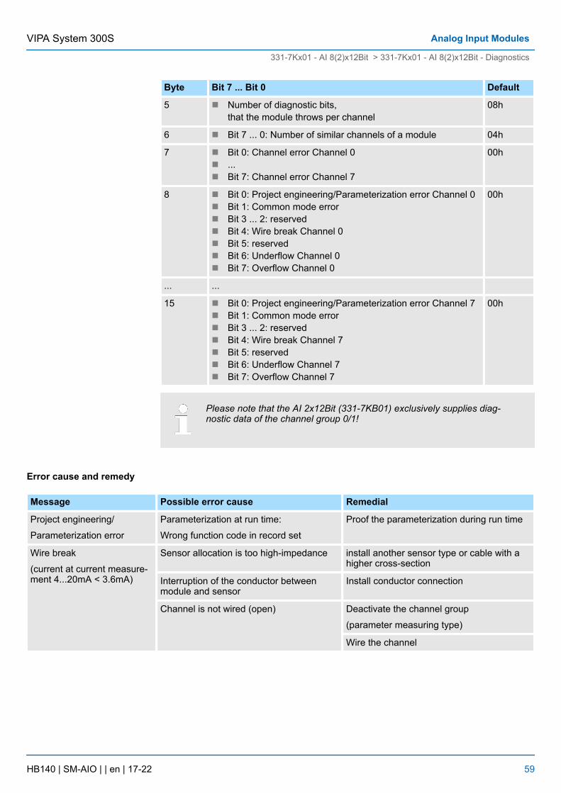
Byte Bit 7 ... Bit 0 Default
5 n Number of diagnostic bits,that the module throws per channel
08h
6 n Bit 7 ... 0: Number of similar channels of a module 04h
7 n Bit 0: Channel error Channel 0n ...n Bit 7: Channel error Channel 7
00h
8 n Bit 0: Project engineering/Parameterization error Channel 0n Bit 1: Common mode errorn Bit 3 ... 2: reservedn Bit 4: Wire break Channel 0n Bit 5: reservedn Bit 6: Underflow Channel 0n Bit 7: Overflow Channel 0
00h
... ...
15 n Bit 0: Project engineering/Parameterization error Channel 7n Bit 1: Common mode errorn Bit 3 ... 2: reservedn Bit 4: Wire break Channel 7n Bit 5: reservedn Bit 6: Underflow Channel 7n Bit 7: Overflow Channel 7
00h
Please note that the AI 2x12Bit (331-7KB01) exclusively supplies diag-nostic data of the channel group 0/1!
Message Possible error cause Remedial
Project engineering/
Parameterization error
Parameterization at run time:
Wrong function code in record set
Proof the parameterization during run time
Wire break
(current at current measure-ment 4...20mA < 3.6mA)
Sensor allocation is too high-impedance install another sensor type or cable with ahigher cross-section
Interruption of the conductor betweenmodule and sensor
Install conductor connection
Channel is not wired (open) Deactivate the channel group
(parameter measuring type)
Wire the channel
Error cause and remedy
VIPA System 300S Analog Input Modules
331-7Kx01 - AI 8(2)x12Bit > 331-7Kx01 - AI 8(2)x12Bit - Diagnostics
HB140 | SM-AIO | | en | 17-22 59
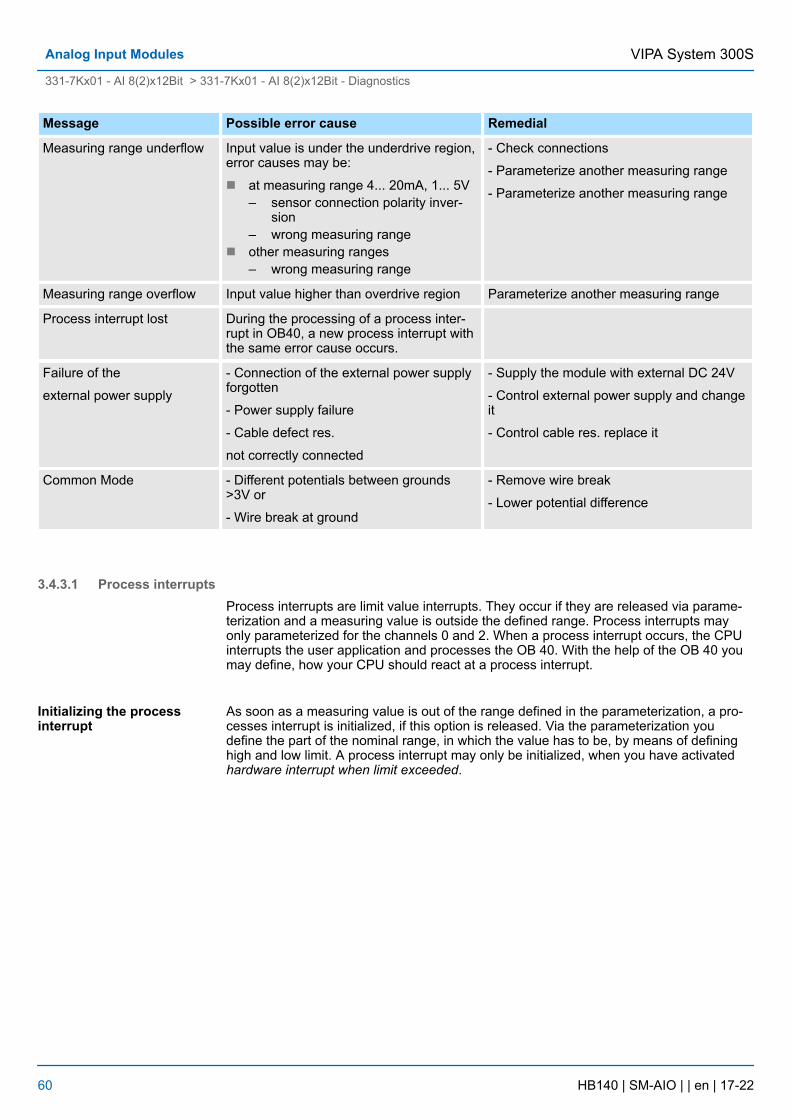
Message Possible error cause Remedial
Measuring range underflow Input value is under the underdrive region,error causes may be:
n at measuring range 4... 20mA, 1... 5V– sensor connection polarity inver-
sion– wrong measuring range
n other measuring ranges– wrong measuring range
- Check connections
- Parameterize another measuring range
- Parameterize another measuring range
Measuring range overflow Input value higher than overdrive region Parameterize another measuring range
Process interrupt lost During the processing of a process inter-rupt in OB40, a new process interrupt withthe same error cause occurs.
Failure of the
external power supply
- Connection of the external power supplyforgotten
- Power supply failure
- Cable defect res.
not correctly connected
- Supply the module with external DC 24V
- Control external power supply and changeit
- Control cable res. replace it
Common Mode - Different potentials between grounds>3V or
- Wire break at ground
- Remove wire break
- Lower potential difference
3.4.3.1 Process interruptsProcess interrupts are limit value interrupts. They occur if they are released via parame-terization and a measuring value is outside the defined range. Process interrupts mayonly parameterized for the channels 0 and 2. When a process interrupt occurs, the CPUinterrupts the user application and processes the OB 40. With the help of the OB 40 youmay define, how your CPU should react at a process interrupt.
As soon as a measuring value is out of the range defined in the parameterization, a pro-cesses interrupt is initialized, if this option is released. Via the parameterization youdefine the part of the nominal range, in which the value has to be, by means of defininghigh and low limit. A process interrupt may only be initialized, when you have activatedhardware interrupt when limit exceeded.
Initializing the processinterrupt
VIPA System 300SAnalog Input Modules
331-7Kx01 - AI 8(2)x12Bit > 331-7Kx01 - AI 8(2)x12Bit - Diagnostics
HB140 | SM-AIO | | en | 17-22 60
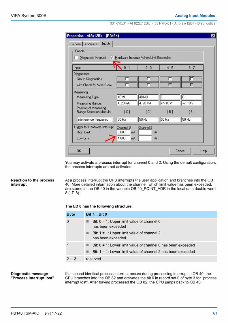
You may activate a process interrupt for channel 0 and 2. Using the default configuration,the process interrupts are not activated.
At a process interrupt the CPU interrupts the user application and branches into the OB40. More detailed information about the channel, which limit value has been exceeded,are stored in the OB 40 in the variable OB 40_POINT_ADR in the local data double word8 (LD 8).
The LD 8 has the following structure:
Byte Bit 7... Bit 0
0 n Bit: 0 = 1: Upper limit value of channel 0has been exceeded
n Bit: 1 = 1: Upper limit value of channel 2has been exceeded
1 n Bit: 0 = 1: Lower limit value of channel 0 has been exceeded
n Bit: 1 = 1: Lower limit value of channel 2 has been exceeded
2 ... 3 reserved
If a second identical process interrupt occurs during processing interrupt in OB 40, theCPU branches into the OB 82 and activates the bit 6 in record set 0 of byte 3 for "processinterrupt lost". After having processed the OB 82, the CPU jumps back to OB 40.
Reaction to the processinterrupt
Diagnostic message"Process interrupt lost"
VIPA System 300S Analog Input Modules
331-7Kx01 - AI 8(2)x12Bit > 331-7Kx01 - AI 8(2)x12Bit - Diagnostics
HB140 | SM-AIO | | en | 17-22 61
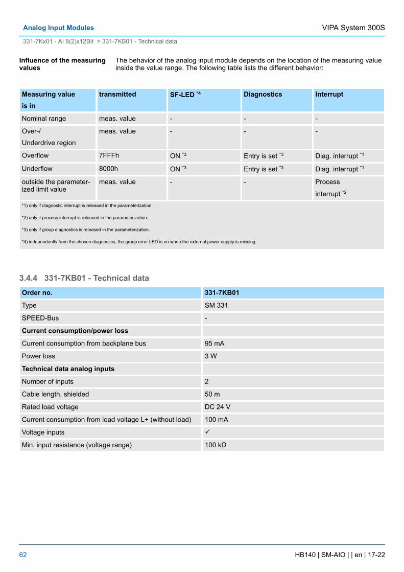
The behavior of the analog input module depends on the location of the measuring valueinside the value range. The following table lists the different behavior:
Measuring valueis in
transmitted SF-LED *4 Diagnostics Interrupt
Nominal range meas. value - - -
Over-/
Underdrive region
meas. value - - -
Overflow 7FFFh ON *3 Entry is set *3 Diag. interrupt *1
Underflow 8000h ON *3 Entry is set *3 Diag. interrupt *1
outside the parameter-ized limit value
meas. value - - Process
interrupt *2
*1) only if diagnostic interrupt is released in the parameterization.
*2) only if process interrupt is released in the parameterization.
*3) only if group diagnostics is released in the parameterization.
*4) independently from the chosen diagnostics, the group error LED is on when the external power supply is missing.
3.4.4 331-7KB01 - Technical dataOrder no. 331-7KB01
Type SM 331
SPEED-Bus -
Current consumption/power loss
Current consumption from backplane bus 95 mA
Power loss 3 W
Technical data analog inputs
Number of inputs 2
Cable length, shielded 50 m
Rated load voltage DC 24 V
Current consumption from load voltage L+ (without load) 100 mA
Voltage inputs ü
Min. input resistance (voltage range) 100 kΩ
Influence of the measuringvalues
VIPA System 300SAnalog Input Modules
331-7Kx01 - AI 8(2)x12Bit > 331-7KB01 - Technical data
HB140 | SM-AIO | | en | 17-22 62
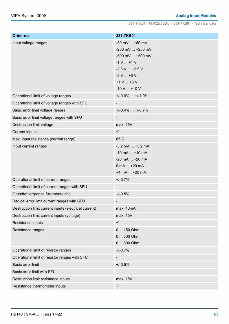
Order no. 331-7KB01
Input voltage ranges -80 mV ... +80 mV
-250 mV ... +250 mV
-500 mV ... +500 mV
-1 V ... +1 V
-2.5 V ... +2.5 V
-5 V ... +5 V
+1 V ... +5 V
-10 V ... +10 V
Operational limit of voltage ranges +/-0.6% ... +/-1.0%
Operational limit of voltage ranges with SFU -
Basic error limit voltage ranges +/-0.4% ... +/-0.7%
Basic error limit voltage ranges with SFU -
Destruction limit voltage max. 15V
Current inputs ü
Max. input resistance (current range) 85 Ω
Input current ranges -3.2 mA ... +3.2 mA
-10 mA ... +10 mA
-20 mA ... +20 mA
0 mA ... +20 mA
+4 mA ... +20 mA
Operational limit of current ranges +/-0.7%
Operational limit of current ranges with SFU -
Grundfehlergrenze Strombereiche +/-0.5%
Radical error limit current ranges with SFU -
Destruction limit current inputs (electrical current) max. 40mA
Destruction limit current inputs (voltage) max. 15V
Resistance inputs ü
Resistance ranges 0 ... 150 Ohm
0 ... 300 Ohm
0 ... 600 Ohm
Operational limit of resistor ranges +/-0.7%
Operational limit of resistor ranges with SFU -
Basic error limit +/-0.5%
Basic error limit with SFU -
Destruction limit resistance inputs max. 15V
Resistance thermometer inputs ü
VIPA System 300S Analog Input Modules
331-7Kx01 - AI 8(2)x12Bit > 331-7KB01 - Technical data
HB140 | SM-AIO | | en | 17-22 63
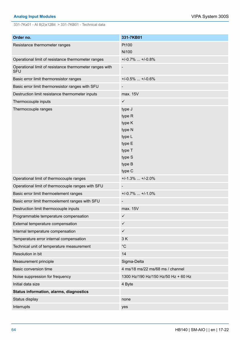
Order no. 331-7KB01
Resistance thermometer ranges Pt100
Ni100
Operational limit of resistance thermometer ranges +/-0.7% ... +/-0.8%
Operational limit of resistance thermometer ranges withSFU
-
Basic error limit thermoresistor ranges +/-0.5% ... +/-0.6%
Basic error limit thermoresistor ranges with SFU -
Destruction limit resistance thermometer inputs max. 15V
Thermocouple inputs ü
Thermocouple ranges type J
type R
type K
type N
type L
type E
type T
type S
type B
type C
Operational limit of thermocouple ranges +/-1.3% ... +/-2.0%
Operational limit of thermocouple ranges with SFU -
Basic error limit thermoelement ranges +/-0.7% ... +/-1.0%
Basic error limit thermoelement ranges with SFU -
Destruction limit thermocouple inputs max. 15V
Programmable temperature compensation ü
External temperature compensation ü
Internal temperature compensation ü
Temperature error internal compensation 3 K
Technical unit of temperature measurement °C
Resolution in bit 14
Measurement principle Sigma-Delta
Basic conversion time 4 ms/18 ms/22 ms/68 ms / channel
Noise suppression for frequency 1300 Hz/190 Hz/150 Hz/50 Hz + 60 Hz
Initial data size 4 Byte
Status information, alarms, diagnostics
Status display none
Interrupts yes
VIPA System 300SAnalog Input Modules
331-7Kx01 - AI 8(2)x12Bit > 331-7KB01 - Technical data
HB140 | SM-AIO | | en | 17-22 64
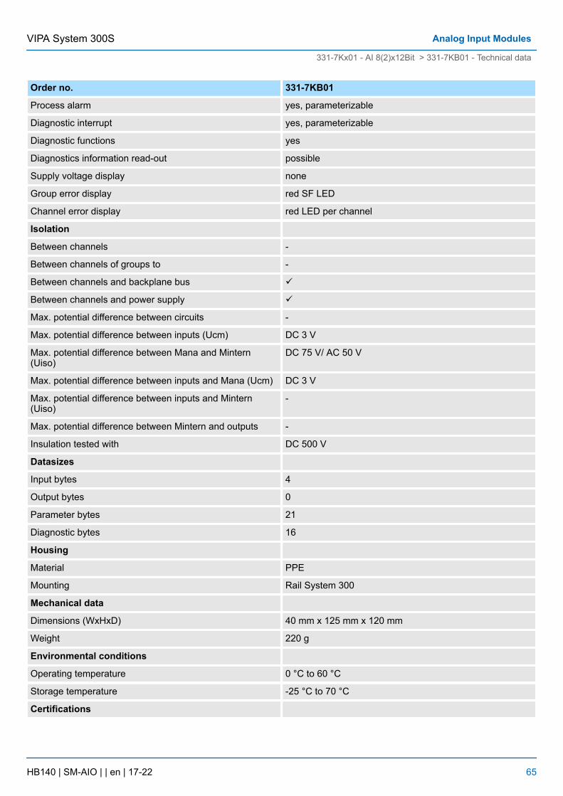
Order no. 331-7KB01
Process alarm yes, parameterizable
Diagnostic interrupt yes, parameterizable
Diagnostic functions yes
Diagnostics information read-out possible
Supply voltage display none
Group error display red SF LED
Channel error display red LED per channel
Isolation
Between channels -
Between channels of groups to -
Between channels and backplane bus ü
Between channels and power supply ü
Max. potential difference between circuits -
Max. potential difference between inputs (Ucm) DC 3 V
Max. potential difference between Mana and Mintern(Uiso)
DC 75 V/ AC 50 V
Max. potential difference between inputs and Mana (Ucm) DC 3 V
Max. potential difference between inputs and Mintern(Uiso)
-
Max. potential difference between Mintern and outputs -
Insulation tested with DC 500 V
Datasizes
Input bytes 4
Output bytes 0
Parameter bytes 21
Diagnostic bytes 16
Housing
Material PPE
Mounting Rail System 300
Mechanical data
Dimensions (WxHxD) 40 mm x 125 mm x 120 mm
Weight 220 g
Environmental conditions
Operating temperature 0 °C to 60 °C
Storage temperature -25 °C to 70 °C
Certifications
VIPA System 300S Analog Input Modules
331-7Kx01 - AI 8(2)x12Bit > 331-7KB01 - Technical data
HB140 | SM-AIO | | en | 17-22 65
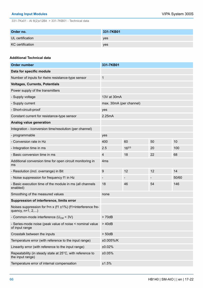
Order no. 331-7KB01
UL certification yes
KC certification yes
Additional Technical data
Order number 331-7KB01
Data for specific module
Number of inputs for 4wire resistance-type sensor 1
Voltages, Currents, Potentials
Power supply of the transmitters
- Supply voltage 13V at 30mA
- Supply current max. 30mA (per channel)
- Short-circuit-proof yes
Constant current for resistance-type sensor 2.25mA
Analog value generation
Integration - /conversion time/resolution (per channel)
- programmable yes
- Conversion rate in Hz 400 60 50 10
- Integration time in ms 2.5 162/3 20 100
- Basic conversion time in ms 4 18 22 68
Additional conversion time for open circuit monitoring inms
4ms
- Resolution (incl. overrange) in Bit 9 12 12 14
- Noise suppression for frequency f1 in Hz - - - 50/60
- Basic execution time of the module in ms (all channelsenabled)
18 46 54 146
Smoothing of the measured values none
Suppression of interference, limits error
Noises suppression for f=n x (f1 ±1%) (f1=interference fre-quency, n=1, 2,...)
- Common-mode interference (UCM < 3V) > 70dB
- Series-mode noise (peak value of noise < nominal valueof input range
> 40dB
Crosstalk between the inputs > 50dB
Temperature error (with reference to the input range) ±0.005%/K
Linearity error (with reference to the input range) ±0.02%
Repeatability (in steady state at 25°C, with reference tothe input range)
±0.05%
Temperature error of internal compensation ±1.5%
VIPA System 300SAnalog Input Modules
331-7Kx01 - AI 8(2)x12Bit > 331-7KB01 - Technical data
HB140 | SM-AIO | | en | 17-22 66

Order number 331-7KB01
Data for selecting a sensor
Input resistance
- Voltage
± 80mV, ± 250mV 10MW
± 500mV, ± 1V 10MW
± 2,5V, ± 5V 100kW
1 ... 5V, ± 10V 100kW
- Current
± 3,2mA, ± 10mA, ± 20mA 85W
0 ... 20mA, 4 ... 20mA 85W
- Resistance
0 ... 150W, 300W, 600W 10MW
- Resistance thermometer
Pt100, NI100 10MW
- Thermocouples
Type J, K, N, L, E, T, S, B, C, R 10MW
Maximum input voltage for voltage input (destruction limit) max. 20V
Maximum input current for current input (destruction limit) max. 40mA
Connection of the sensors
- for measuring voltage possible
- for measuring current
as 2wire transmitter possible
as 4wire transmitter possible
- for measuring resistance
with 2conductor connection possible
with 3conductor connection possible
with 4conductor connection possible
Characteristic linearization
- for RTD Pt100, NI 100 Standard / Climate
- for thermocouples Type E, N, J, K, L, T, S, B, C, R, Ni100 Standard / Climate
Temperature compensation parameterizable
- internal temperature compensation possible
- external temperature compensation with compensatingbox
possible
- Compensation for 0°C comparison point temperature possible
Technical unit for temperature measurement °C
VIPA System 300S Analog Input Modules
331-7Kx01 - AI 8(2)x12Bit > 331-7KB01 - Technical data
HB140 | SM-AIO | | en | 17-22 67
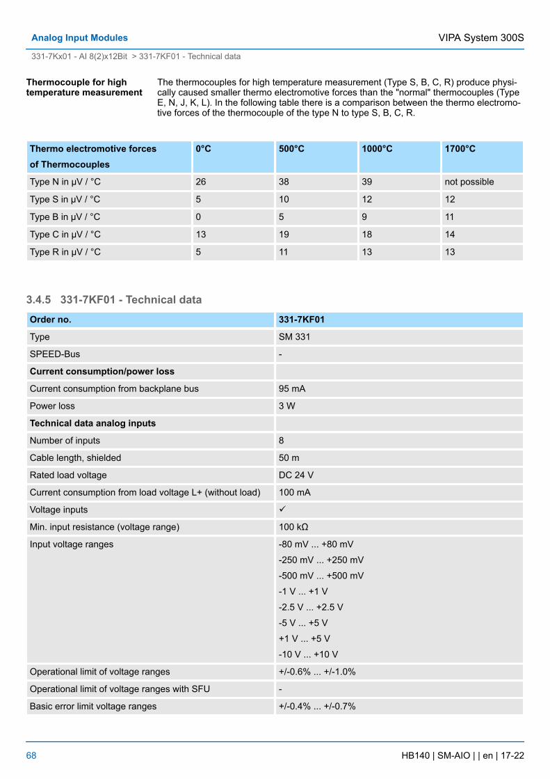
The thermocouples for high temperature measurement (Type S, B, C, R) produce physi-cally caused smaller thermo electromotive forces than the "normal" thermocouples (TypeE, N, J, K, L). In the following table there is a comparison between the thermo electromo-tive forces of the thermocouple of the type N to type S, B, C, R.
Thermo electromotive forcesof Thermocouples
0°C 500°C 1000°C 1700°C
Type N in µV / °C 26 38 39 not possible
Type S in µV / °C 5 10 12 12
Type B in µV / °C 0 5 9 11
Type C in µV / °C 13 19 18 14
Type R in µV / °C 5 11 13 13
3.4.5 331-7KF01 - Technical dataOrder no. 331-7KF01
Type SM 331
SPEED-Bus -
Current consumption/power loss
Current consumption from backplane bus 95 mA
Power loss 3 W
Technical data analog inputs
Number of inputs 8
Cable length, shielded 50 m
Rated load voltage DC 24 V
Current consumption from load voltage L+ (without load) 100 mA
Voltage inputs ü
Min. input resistance (voltage range) 100 kΩ
Input voltage ranges -80 mV ... +80 mV
-250 mV ... +250 mV
-500 mV ... +500 mV
-1 V ... +1 V
-2.5 V ... +2.5 V
-5 V ... +5 V
+1 V ... +5 V
-10 V ... +10 V
Operational limit of voltage ranges +/-0.6% ... +/-1.0%
Operational limit of voltage ranges with SFU -
Basic error limit voltage ranges +/-0.4% ... +/-0.7%
Thermocouple for hightemperature measurement
VIPA System 300SAnalog Input Modules
331-7Kx01 - AI 8(2)x12Bit > 331-7KF01 - Technical data
HB140 | SM-AIO | | en | 17-22 68
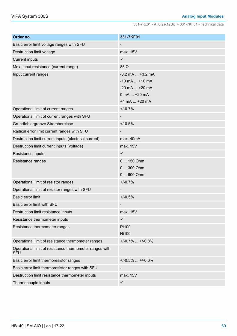
Order no. 331-7KF01
Basic error limit voltage ranges with SFU -
Destruction limit voltage max. 15V
Current inputs ü
Max. input resistance (current range) 85 Ω
Input current ranges -3.2 mA ... +3.2 mA
-10 mA ... +10 mA
-20 mA ... +20 mA
0 mA ... +20 mA
+4 mA ... +20 mA
Operational limit of current ranges +/-0.7%
Operational limit of current ranges with SFU -
Grundfehlergrenze Strombereiche +/-0.5%
Radical error limit current ranges with SFU -
Destruction limit current inputs (electrical current) max. 40mA
Destruction limit current inputs (voltage) max. 15V
Resistance inputs ü
Resistance ranges 0 ... 150 Ohm
0 ... 300 Ohm
0 ... 600 Ohm
Operational limit of resistor ranges +/-0.7%
Operational limit of resistor ranges with SFU -
Basic error limit +/-0.5%
Basic error limit with SFU -
Destruction limit resistance inputs max. 15V
Resistance thermometer inputs ü
Resistance thermometer ranges Pt100
Ni100
Operational limit of resistance thermometer ranges +/-0.7% ... +/-0.8%
Operational limit of resistance thermometer ranges withSFU
-
Basic error limit thermoresistor ranges +/-0.5% ... +/-0.6%
Basic error limit thermoresistor ranges with SFU -
Destruction limit resistance thermometer inputs max. 15V
Thermocouple inputs ü
VIPA System 300S Analog Input Modules
331-7Kx01 - AI 8(2)x12Bit > 331-7KF01 - Technical data
HB140 | SM-AIO | | en | 17-22 69
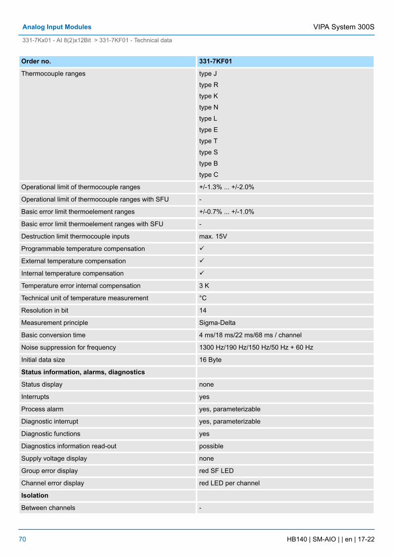
Order no. 331-7KF01
Thermocouple ranges type J
type R
type K
type N
type L
type E
type T
type S
type B
type C
Operational limit of thermocouple ranges +/-1.3% ... +/-2.0%
Operational limit of thermocouple ranges with SFU -
Basic error limit thermoelement ranges +/-0.7% ... +/-1.0%
Basic error limit thermoelement ranges with SFU -
Destruction limit thermocouple inputs max. 15V
Programmable temperature compensation ü
External temperature compensation ü
Internal temperature compensation ü
Temperature error internal compensation 3 K
Technical unit of temperature measurement °C
Resolution in bit 14
Measurement principle Sigma-Delta
Basic conversion time 4 ms/18 ms/22 ms/68 ms / channel
Noise suppression for frequency 1300 Hz/190 Hz/150 Hz/50 Hz + 60 Hz
Initial data size 16 Byte
Status information, alarms, diagnostics
Status display none
Interrupts yes
Process alarm yes, parameterizable
Diagnostic interrupt yes, parameterizable
Diagnostic functions yes
Diagnostics information read-out possible
Supply voltage display none
Group error display red SF LED
Channel error display red LED per channel
Isolation
Between channels -
VIPA System 300SAnalog Input Modules
331-7Kx01 - AI 8(2)x12Bit > 331-7KF01 - Technical data
HB140 | SM-AIO | | en | 17-22 70
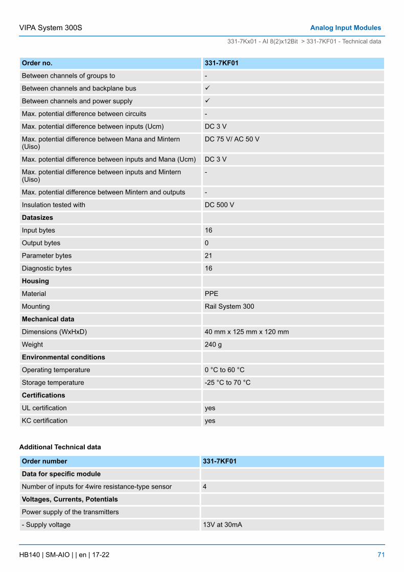
Order no. 331-7KF01
Between channels of groups to -
Between channels and backplane bus ü
Between channels and power supply ü
Max. potential difference between circuits -
Max. potential difference between inputs (Ucm) DC 3 V
Max. potential difference between Mana and Mintern(Uiso)
DC 75 V/ AC 50 V
Max. potential difference between inputs and Mana (Ucm) DC 3 V
Max. potential difference between inputs and Mintern(Uiso)
-
Max. potential difference between Mintern and outputs -
Insulation tested with DC 500 V
Datasizes
Input bytes 16
Output bytes 0
Parameter bytes 21
Diagnostic bytes 16
Housing
Material PPE
Mounting Rail System 300
Mechanical data
Dimensions (WxHxD) 40 mm x 125 mm x 120 mm
Weight 240 g
Environmental conditions
Operating temperature 0 °C to 60 °C
Storage temperature -25 °C to 70 °C
Certifications
UL certification yes
KC certification yes
Additional Technical data
Order number 331-7KF01
Data for specific module
Number of inputs for 4wire resistance-type sensor 4
Voltages, Currents, Potentials
Power supply of the transmitters
- Supply voltage 13V at 30mA
VIPA System 300S Analog Input Modules
331-7Kx01 - AI 8(2)x12Bit > 331-7KF01 - Technical data
HB140 | SM-AIO | | en | 17-22 71
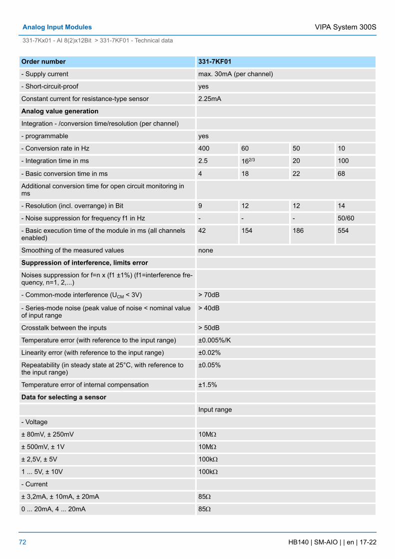
Order number 331-7KF01
- Supply current max. 30mA (per channel)
- Short-circuit-proof yes
Constant current for resistance-type sensor 2.25mA
Analog value generation
Integration - /conversion time/resolution (per channel)
- programmable yes
- Conversion rate in Hz 400 60 50 10
- Integration time in ms 2.5 162/3 20 100
- Basic conversion time in ms 4 18 22 68
Additional conversion time for open circuit monitoring inms
- Resolution (incl. overrange) in Bit 9 12 12 14
- Noise suppression for frequency f1 in Hz - - - 50/60
- Basic execution time of the module in ms (all channelsenabled)
42 154 186 554
Smoothing of the measured values none
Suppression of interference, limits error
Noises suppression for f=n x (f1 ±1%) (f1=interference fre-quency, n=1, 2,...)
- Common-mode interference (UCM < 3V) > 70dB
- Series-mode noise (peak value of noise < nominal valueof input range
> 40dB
Crosstalk between the inputs > 50dB
Temperature error (with reference to the input range) ±0.005%/K
Linearity error (with reference to the input range) ±0.02%
Repeatability (in steady state at 25°C, with reference tothe input range)
±0.05%
Temperature error of internal compensation ±1.5%
Data for selecting a sensor
Input range
- Voltage
± 80mV, ± 250mV 10MW
± 500mV, ± 1V 10MW
± 2,5V, ± 5V 100kW
1 ... 5V, ± 10V 100kW
- Current
± 3,2mA, ± 10mA, ± 20mA 85W
0 ... 20mA, 4 ... 20mA 85W
VIPA System 300SAnalog Input Modules
331-7Kx01 - AI 8(2)x12Bit > 331-7KF01 - Technical data
HB140 | SM-AIO | | en | 17-22 72
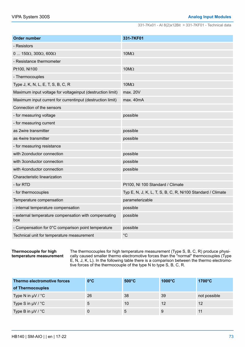
Order number 331-7KF01
- Resistors
0 ... 150W, 300W, 600W 10MW
- Resistance thermometer
Pt100, NI100 10MW
- Thermocouples
Type J, K, N, L, E, T, S, B, C, R 10MW
Maximum input voltage for voltageinput (destruction limit) max. 20V
Maximum input current for currentinput (destruction limit) max. 40mA
Connection of the sensors
- for measuring voltage possible
- for measuring current
as 2wire transmitter possible
as 4wire transmitter possible
- for measuring resistance
with 2conductor connection possible
with 3conductor connection possible
with 4conductor connection possible
Characteristic linearization
- for RTD Pt100, NI 100 Standard / Climate
- for thermocouples Typ E, N, J, K, L, T, S, B, C, R, Ni100 Standard / Climate
Temperature compensation parameterizable
- internal temperature compensation possible
- external temperature compensation with compensatingbox
possible
- Compensation for 0°C comparison point temperature possible
Technical unit for temperature measurement °C
The thermocouples for high temperature measurement (Type S, B, C, R) produce physi-cally caused smaller thermo electromotive forces than the "normal" thermocouples (TypeE, N, J, K, L). In the following table there is a comparison between the thermo electromo-tive forces of the thermocouple of the type N to type S, B, C, R.
Thermo electromotive forcesof Thermocouples
0°C 500°C 1000°C 1700°C
Type N in µV / °C 26 38 39 not possible
Type S in µV / °C 5 10 12 12
Type B in µV / °C 0 5 9 11
Thermocouple for hightemperature measurement
VIPA System 300S Analog Input Modules
331-7Kx01 - AI 8(2)x12Bit > 331-7KF01 - Technical data
HB140 | SM-AIO | | en | 17-22 73
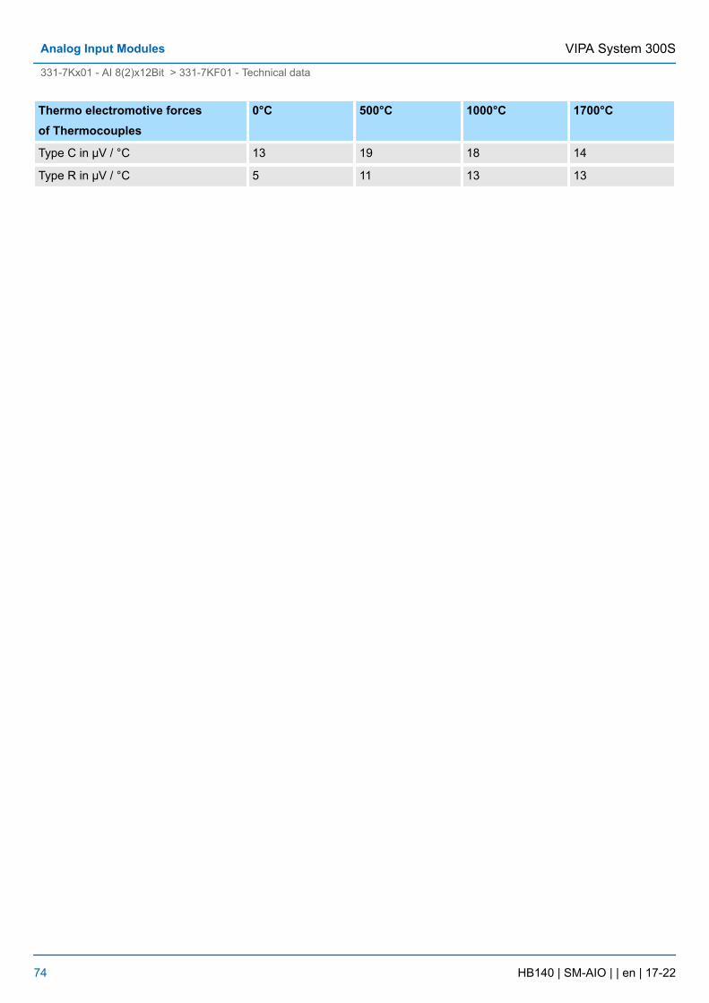
Thermo electromotive forcesof Thermocouples
0°C 500°C 1000°C 1700°C
Type C in µV / °C 13 19 18 14
Type R in µV / °C 5 11 13 13
VIPA System 300SAnalog Input Modules
331-7Kx01 - AI 8(2)x12Bit > 331-7KF01 - Technical data
HB140 | SM-AIO | | en | 17-22 74
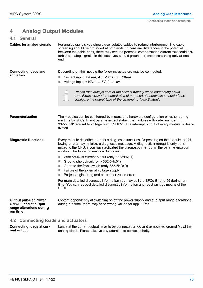
4 Analog Output Modules4.1 General
For analog signals you should use isolated cables to reduce interference. The cablescreening should be grounded at both ends. If there are differences in the potentialbetween the cable ends, there may occur a potential compensating current that could dis-turb the analog signals. In this case you should ground the cable screening only at oneend.
Depending on the module the following actuators may be connected:
n Current input: ±20mA, 4 ... 20mA, 0 ... 20mAn Voltage input: ±10V, 1 ... 5V, 0 ... 10V
Please take always care of the correct polarity when connecting actua-tors! Please leave the output pins of not used channels disconnected andconfigure the output type of the channel to "deactivated".
The modules can be configured by means of a hardware configuration or rather duringrun time by SFCs. In not parameterized status, the modules with order number332-5Hx01 are set to voltage output "±10V". The interrupt output of every module is deac-tivated.
Every module described here has diagnostic functions. Depending on the module the fol-lowing errors may initialize a diagnostic message: A diagnostic interrupt is only trans-mitted to the CPU, if you have activated the diagnostic interrupt in the parameterizationwindow. The following errors a diagnosis:
n Wire break at current output (only 332-5Hx01)n Ground short circuit (only 332-5Hx01)n Operate the front switch (only 332-5HDx0)n Failure of the external voltage supplyn Project engineering and parameterization error
For more detailed diagnostic information you may call the SFCs 51 and 59 during runtime. You can request detailed diagnostic information and react on it by means of theSFCs.
System-dependently at switching on/off the power supply and at output range alterationsduring run time, there may arise wrong values for app. 10ms.
4.2 Connecting loads and actuatorsLoads at the current output have to be connected at QX and associated ground MX of theanalog circuit. Please always pay attention to correct polarity.
Cables for analog signals
Connecting loads andactuators
Parameterization
Diagnostic functions
Output pulse at PowerON/OFF and at outputrange alterations duringrun time
Connecting loads at cur-rent output
VIPA System 300S Analog Output Modules
Connecting loads and actuators
HB140 | SM-AIO | | en | 17-22 75
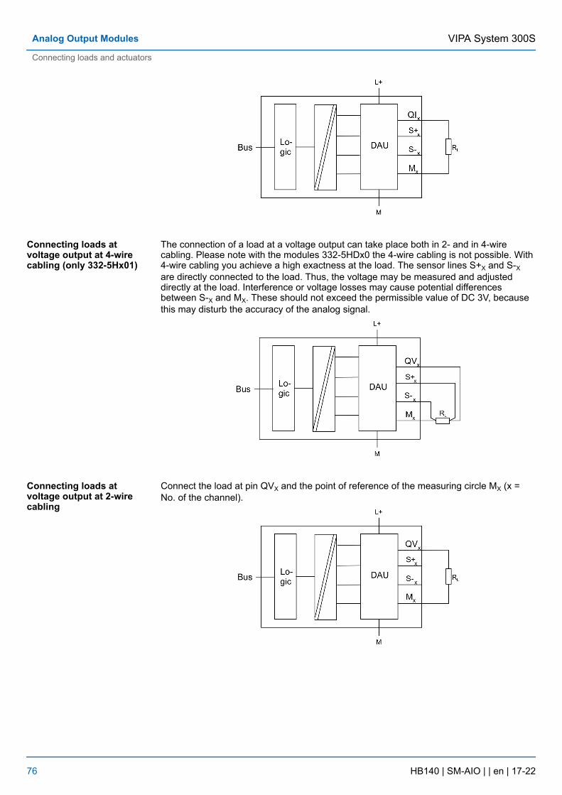
The connection of a load at a voltage output can take place both in 2- and in 4-wirecabling. Please note with the modules 332-5HDx0 the 4-wire cabling is not possible. With4-wire cabling you achieve a high exactness at the load. The sensor lines S+X and S-Xare directly connected to the load. Thus, the voltage may be measured and adjusteddirectly at the load. Interference or voltage losses may cause potential differencesbetween S-X and MX. These should not exceed the permissible value of DC 3V, becausethis may disturb the accuracy of the analog signal.
Connect the load at pin QVX and the point of reference of the measuring circle MX (x =No. of the channel).
Connecting loads atvoltage output at 4-wirecabling (only 332-5Hx01)
Connecting loads atvoltage output at 2-wirecabling
VIPA System 300SAnalog Output Modules
Connecting loads and actuators
HB140 | SM-AIO | | en | 17-22 76
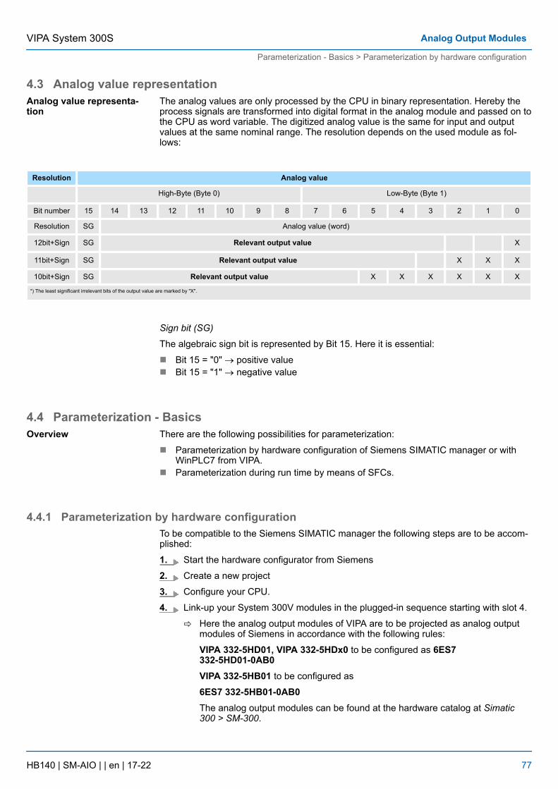
4.3 Analog value representationThe analog values are only processed by the CPU in binary representation. Hereby theprocess signals are transformed into digital format in the analog module and passed on tothe CPU as word variable. The digitized analog value is the same for input and outputvalues at the same nominal range. The resolution depends on the used module as fol-lows:
Resolution Analog value
High-Byte (Byte 0) Low-Byte (Byte 1)
Bit number 15 14 13 12 11 10 9 8 7 6 5 4 3 2 1 0
Resolution SG Analog value (word)
12bit+Sign SG Relevant output value X
11bit+Sign SG Relevant output value X X X
10bit+Sign SG Relevant output value X X X X X X
*) The least significant irrelevant bits of the output value are marked by "X".
Sign bit (SG)
The algebraic sign bit is represented by Bit 15. Here it is essential:
n Bit 15 = "0" ® positive valuen Bit 15 = "1" ® negative value
4.4 Parameterization - BasicsThere are the following possibilities for parameterization:
n Parameterization by hardware configuration of Siemens SIMATIC manager or withWinPLC7 from VIPA.
n Parameterization during run time by means of SFCs.
4.4.1 Parameterization by hardware configurationTo be compatible to the Siemens SIMATIC manager the following steps are to be accom-plished:
1. Start the hardware configurator from Siemens
2. Create a new project
3. Configure your CPU.
4. Link-up your System 300V modules in the plugged-in sequence starting with slot 4.
ð Here the analog output modules of VIPA are to be projected as analog outputmodules of Siemens in accordance with the following rules:
VIPA 332-5HD01, VIPA 332-5HDx0 to be configured as 6ES7332-5HD01-0AB0VIPA 332-5HB01 to be configured as
6ES7 332-5HB01-0AB0The analog output modules can be found at the hardware catalog at Simatic300 > SM-300.
Analog value representa-tion
Overview
VIPA System 300S Analog Output Modules
Parameterization - Basics > Parameterization by hardware configuration
HB140 | SM-AIO | | en | 17-22 77
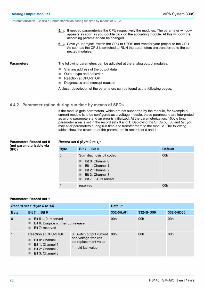
5. If needed parameterize the CPU respectively the modules. The parameter windowappears as soon as you double click on the according module. At this window theaccording parameter can be changed.
6. Save your project, switch the CPU to STOP and transfer your project to the CPU.As soon as the CPU is switched to RUN the parameters are transferred to the con-nected modules.
The following parameters can be adjusted at the analog output modules:
n Starting address of the output datan Output type and behaviorn Reaction at CPU-STOPn Diagnostics and interrupt reaction
A closer description of the parameters can be found at the following pages.
4.4.2 Parameterization during run time by means of SFCsIf the module gets parameters, which are not supported by the module, for example acurrent module is to be configured as a voltage module, these parameters are interpretedas wrong parameters and an error is initialized. At the parameterization, 16byte longparameter area is set in the record sets 0 and 1. Deploying the SFCs 55, 56 and 57, youmay alter parameters during run time and transfer them to the module. The followingtables show the structure of the parameters in record set 0 and 1:
Record set 0 (Byte 0 to 1):
Byte Bit 7 ... Bit 0 Default
0 Sum diagnosis bit coded
n Bit 0: Channel 0n Bit 1: Channel 1n Bit 2: Channel 2n Bit 3: Channel 3n Bit 7 ... 4: reserved
00h
1 reserved 00h
Parameters Record set 1
Record set 1 (Byte 0 to 13): Default
Byte Bit 7 ... Bit 0 332-5Hx01 332-5HD50 332-5HD60
0 n Bit 5 ... 0: reservedn Bit 6: Diagnostic interrupt releasen Bit 7: reserved
00h 00h 00h
1 Reaction at CPU-STOP
n Bit 0: Channel 0n Bit 1: Channel 1n Bit 2: Channel 2n Bit 3: Channel 3
0: Switch output currentand voltage free res.set replacement value
1: hold last value
00h 00h 00h
Parameters
Parameters Record set 0(not parameterizable viaSFC)
VIPA System 300SAnalog Output Modules
Parameterization - Basics > Parameterization during run time by means of SFCs
HB140 | SM-AIO | | en | 17-22 78
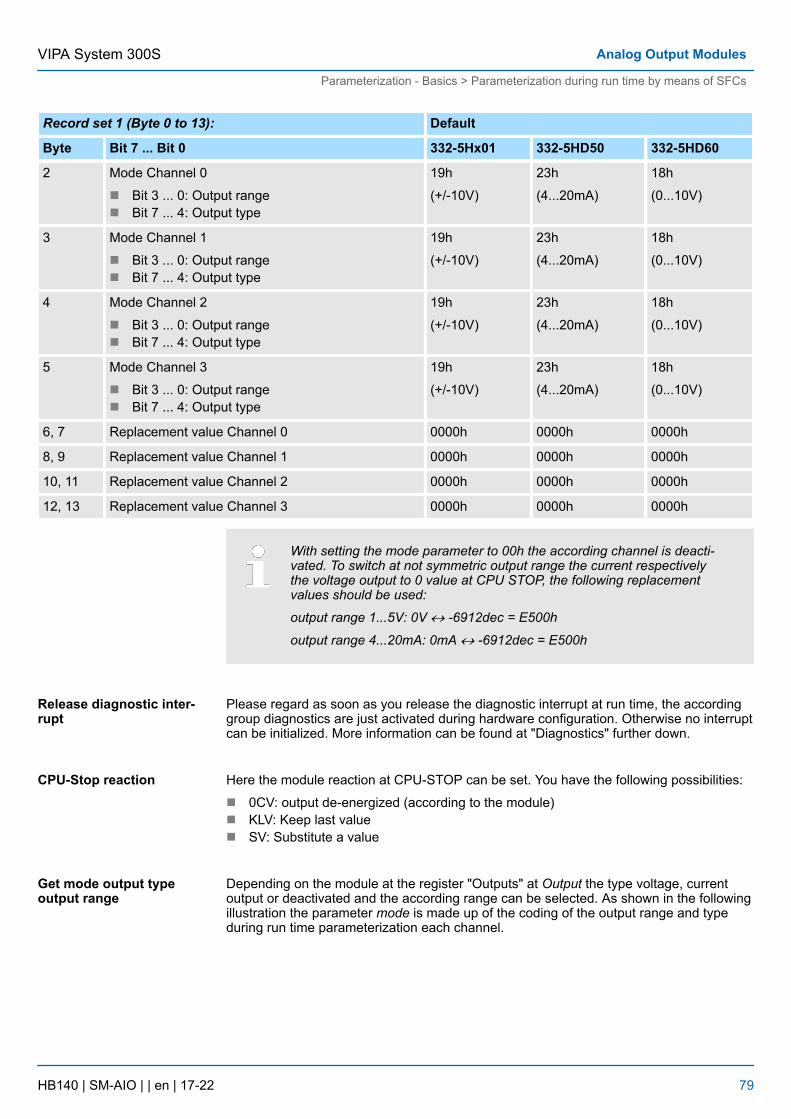
Record set 1 (Byte 0 to 13): Default
Byte Bit 7 ... Bit 0 332-5Hx01 332-5HD50 332-5HD60
2 Mode Channel 0
n Bit 3 ... 0: Output rangen Bit 7 ... 4: Output type
19h
(+/-10V)
23h
(4...20mA)
18h
(0...10V)
3 Mode Channel 1
n Bit 3 ... 0: Output rangen Bit 7 ... 4: Output type
19h
(+/-10V)
23h
(4...20mA)
18h
(0...10V)
4 Mode Channel 2
n Bit 3 ... 0: Output rangen Bit 7 ... 4: Output type
19h
(+/-10V)
23h
(4...20mA)
18h
(0...10V)
5 Mode Channel 3
n Bit 3 ... 0: Output rangen Bit 7 ... 4: Output type
19h
(+/-10V)
23h
(4...20mA)
18h
(0...10V)
6, 7 Replacement value Channel 0 0000h 0000h 0000h
8, 9 Replacement value Channel 1 0000h 0000h 0000h
10, 11 Replacement value Channel 2 0000h 0000h 0000h
12, 13 Replacement value Channel 3 0000h 0000h 0000h
With setting the mode parameter to 00h the according channel is deacti-vated. To switch at not symmetric output range the current respectivelythe voltage output to 0 value at CPU STOP, the following replacementvalues should be used:
output range 1...5V: 0V « -6912dec = E500h
output range 4...20mA: 0mA « -6912dec = E500h
Please regard as soon as you release the diagnostic interrupt at run time, the accordinggroup diagnostics are just activated during hardware configuration. Otherwise no interruptcan be initialized. More information can be found at "Diagnostics" further down.
Here the module reaction at CPU-STOP can be set. You have the following possibilities:
n 0CV: output de-energized (according to the module)n KLV: Keep last valuen SV: Substitute a value
Depending on the module at the register "Outputs" at Output the type voltage, currentoutput or deactivated and the according range can be selected. As shown in the followingillustration the parameter mode is made up of the coding of the output range and typeduring run time parameterization each channel.
Release diagnostic inter-rupt
CPU-Stop reaction
Get mode output typeoutput range
VIPA System 300S Analog Output Modules
Parameterization - Basics > Parameterization during run time by means of SFCs
HB140 | SM-AIO | | en | 17-22 79
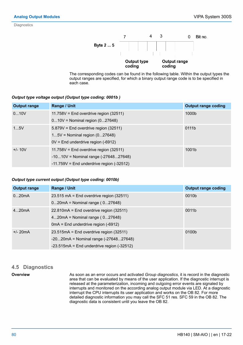
The corresponding codes can be found in the following table. Within the output types theoutput ranges are specified, for which a binary output range code is to be specified ineach case.
Output type voltage output (Output type coding: 0001b )
Output range Range / Unit Output range coding
0...10V 11.758V = End overdrive region (32511)
0...10V = Nominal region (0...27648)
1000b
1...5V 5.879V = End overdrive region (32511)
1...5V = Nominal region (0...27648)
0V = End underdrive region (-6912)
0111b
+/- 10V 11.758V = End overdrive region (32511)
-10...10V = Nominal range (-27648...27648)
-11.759V = End underdrive region (-32512)
1001b
Output type current output (Output type coding: 0010b)
Output range Range / Unit Output range coding
0...20mA 23.515 mA = End overdrive region (32511)
0...20mA = Nominal range ( 0...27648)
0010b
4...20mA 22.810mA = End overdrive region (32511)
4...20mA = Nominal range ( 0...27648)
0mA = End underdrive region (-6912)
0011b
+/- 20mA 23.515mA = End overdrive region (32511)
-20...20mA = Nominal range (-27648...27648)
-23.515mA = End underdrive region (-32512)
0100b
4.5 DiagnosticsAs soon as an error occurs and activated Group diagnostics, it is record in the diagnosticarea that can be evaluated by means of the user application. If the diagnostic interrupt isreleased at the parameterization, incoming and outgoing error events are signaled byinterrupts and monitored on the according analog output module via LED. At a diagnosticinterrupt the CPU interrupts its user application and works on the OB 82. For moredetailed diagnostic information you may call the SFC 51 res. SFC 59 in the OB 82. Thediagnostic data is consistent until you leave the OB 82.
Overview
VIPA System 300SAnalog Output Modules
Diagnostics
HB140 | SM-AIO | | en | 17-22 80
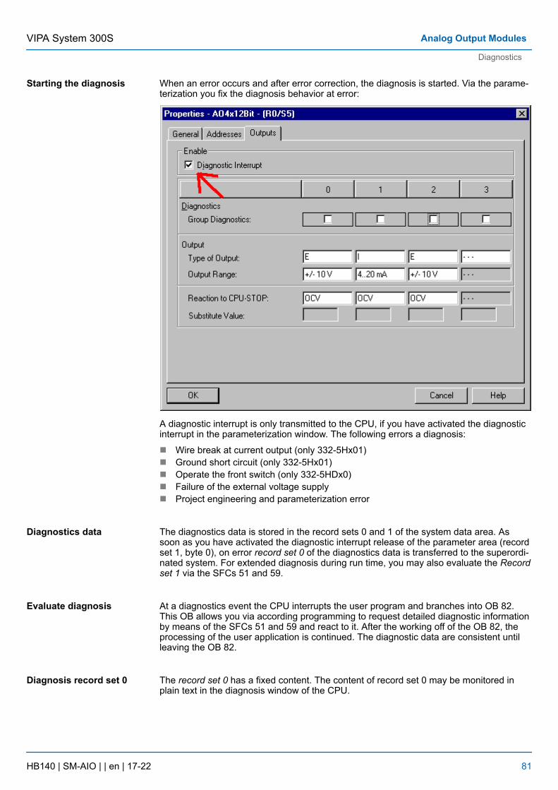
When an error occurs and after error correction, the diagnosis is started. Via the parame-terization you fix the diagnosis behavior at error:
A diagnostic interrupt is only transmitted to the CPU, if you have activated the diagnosticinterrupt in the parameterization window. The following errors a diagnosis:
n Wire break at current output (only 332-5Hx01)n Ground short circuit (only 332-5Hx01)n Operate the front switch (only 332-5HDx0)n Failure of the external voltage supplyn Project engineering and parameterization error
The diagnostics data is stored in the record sets 0 and 1 of the system data area. Assoon as you have activated the diagnostic interrupt release of the parameter area (recordset 1, byte 0), on error record set 0 of the diagnostics data is transferred to the superordi-nated system. For extended diagnosis during run time, you may also evaluate the Recordset 1 via the SFCs 51 and 59.
At a diagnostics event the CPU interrupts the user program and branches into OB 82.This OB allows you via according programming to request detailed diagnostic informationby means of the SFCs 51 and 59 and react to it. After the working off of the OB 82, theprocessing of the user application is continued. The diagnostic data are consistent untilleaving the OB 82.
The record set 0 has a fixed content. The content of record set 0 may be monitored inplain text in the diagnosis window of the CPU.
Starting the diagnosis
Diagnostics data
Evaluate diagnosis
Diagnosis record set 0
VIPA System 300S Analog Output Modules
Diagnostics
HB140 | SM-AIO | | en | 17-22 81
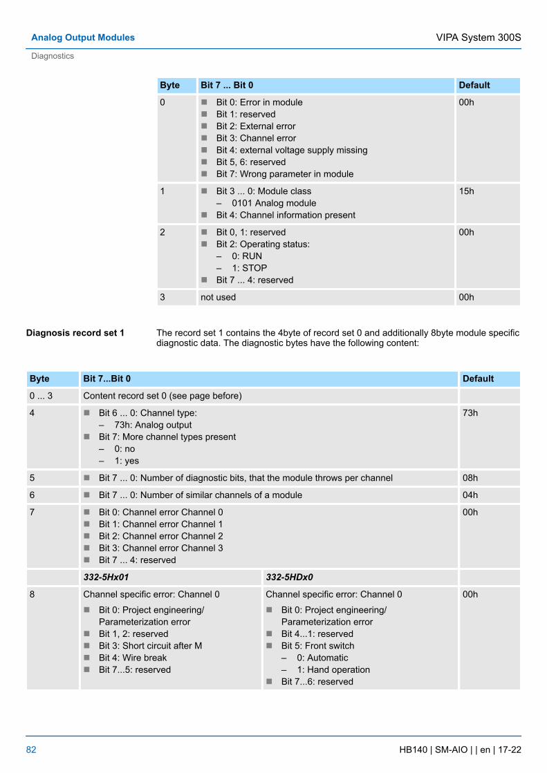
Byte Bit 7 ... Bit 0 Default
0 n Bit 0: Error in modulen Bit 1: reservedn Bit 2: External errorn Bit 3: Channel errorn Bit 4: external voltage supply missingn Bit 5, 6: reservedn Bit 7: Wrong parameter in module
00h
1 n Bit 3 ... 0: Module class– 0101 Analog module
n Bit 4: Channel information present
15h
2 n Bit 0, 1: reservedn Bit 2: Operating status:
– 0: RUN– 1: STOP
n Bit 7 ... 4: reserved
00h
3 not used 00h
The record set 1 contains the 4byte of record set 0 and additionally 8byte module specificdiagnostic data. The diagnostic bytes have the following content:
Byte Bit 7...Bit 0 Default
0 ... 3 Content record set 0 (see page before)
4 n Bit 6 ... 0: Channel type:– 73h: Analog output
n Bit 7: More channel types present– 0: no– 1: yes
73h
5 n Bit 7 ... 0: Number of diagnostic bits, that the module throws per channel 08h
6 n Bit 7 ... 0: Number of similar channels of a module 04h
7 n Bit 0: Channel error Channel 0n Bit 1: Channel error Channel 1n Bit 2: Channel error Channel 2n Bit 3: Channel error Channel 3n Bit 7 ... 4: reserved
00h
332-5Hx01 332-5HDx0
8 Channel specific error: Channel 0
n Bit 0: Project engineering/Parameterization error
n Bit 1, 2: reservedn Bit 3: Short circuit after Mn Bit 4: Wire breakn Bit 7...5: reserved
Channel specific error: Channel 0
n Bit 0: Project engineering/Parameterization error
n Bit 4...1: reservedn Bit 5: Front switch
– 0: Automatic– 1: Hand operation
n Bit 7...6: reserved
00h
Diagnosis record set 1
VIPA System 300SAnalog Output Modules
Diagnostics
HB140 | SM-AIO | | en | 17-22 82
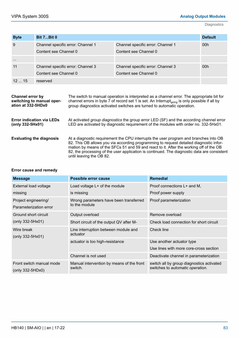
Byte Bit 7...Bit 0 Default
9 Channel specific error: Channel 1
Content see Channel 0
Channel specific error: Channel 1
Content see Channel 0
00h
...
11 Channel specific error: Channel 3
Content see Channel 0
Channel specific error: Channel 3
Content see Channel 0
00h
12 ... 15 reserved
The switch to manual operation is interpreted as a channel error. The appropriate bit forchannel errors in byte 7 of record set 1 is set. An Interruptgoing is only possible if all bygroup diagnostics activated switches are turned to automatic operation.
At activated group diagnostics the group error LED (SF) and the according channel errorLED are activated by diagnostic requirement of the modules with order no. 332-5Hx01.
At a diagnostic requirement the CPU interrupts the user program and branches into OB82. This OB allows you via according programming to request detailed diagnostic infor-mation by means of the SFCs 51 and 59 and react to it. After the working off of the OB82, the processing of the user application is continued. The diagnostic data are consistentuntil leaving the OB 82.
Message Possible error cause Remedial
External load voltage
missing
Load voltage L+ of the module
is missing
Proof connections L+ and M,
Proof power supply
Project engineering/
Parameterization error
Wrong parameters have been transferredto the module
Proof parameterization
Ground short circuit
(only 332-5Hx01)
Output overload Remove overload
Short circuit of the output QV after M- Check load connection for short circuit
Wire break
(only 332-5Hx01)
Line interruption between module andactuator
Check line
actuator is too high-resistance Use another actuator type
Use lines with more core-cross section
Channel is not used Deactivate channel in parameterization
Front switch manual mode
(only 332-5HDx0)
Manual intervention by means of the frontswitch.
switch all by group diagnostics activatedswitches to automatic operation.
Channel error byswitching to manual oper-ation at 332-5HDx0
Error indication via LEDs(only 332-5Hx01)
Evaluating the diagnosis
Error cause and remedy
VIPA System 300S Analog Output Modules
Diagnostics
HB140 | SM-AIO | | en | 17-22 83
4.6 332-5HB01 - AO 2/4x12Bit U/I 2-channelThere are 2 analog outputs which functions may be parameterized individually. Themodule has to be provided with external DC 24V.
n 2 individual parameterizable outputsn the outputs are parameterizable per channel as
– voltage output– current output– deactivated
n usable for actuators with inputs of– ±10V– 1 ... 5V– 0 ... 10V– ±20mA– 4 ... 20mA– 0 ... 20mA
n parameterizable diagnostics and diagnostics interruptn isolated between backplane bus and load voltage
After Power ON, the module has the following default settings:
n Output range: ±10V for all channelsn Interrupts are deactivated
The module is to be projected as Siemens analog output module 6ES7332-5HB01-0AB0.
The deployment of the module at the active backplane bus is not pos-sible!
Properties
Measuring range afterPower ON
VIPA System 300SAnalog Output Modules
332-5HB01 - AO 2/4x12Bit U/I 2-channel
HB140 | SM-AIO | | en | 17-22 84

1 LEDs2 flap with labeling strip3 contact bar4 flap opened with inner label
Structure
VIPA System 300S Analog Output Modules
332-5HB01 - AO 2/4x12Bit U/I 2-channel
HB140 | SM-AIO | | en | 17-22 85
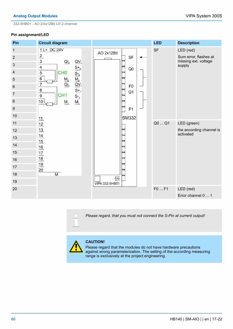
Pin assignment/LED
Pin Circuit diagram LED Description
1 SF LED (red)
Sum error, flashes atmissing ext. voltagesupply
2
3
4
5
6
7
8
9
10
11 Q0 ... Q1 LED (green)
the according channel isactivated
12
13
14
15
16
17
18
19
20 F0 ... F1 LED (red)
Error channel 0 ... 1
Please regard, that you must not connect the S-Pin at current output!
CAUTION!Please regard that the modules do not have hardware precautionsagainst wrong parameterization. The setting of the according measuringrange is exclusively at the project engineering.
VIPA System 300SAnalog Output Modules
332-5HB01 - AO 2/4x12Bit U/I 2-channel
HB140 | SM-AIO | | en | 17-22 86
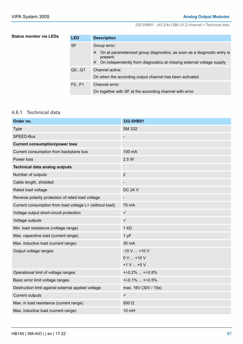
LED Description
SF Group error:
n On at parameterized group diagnostics, as soon as a diagnostic entry ispresent.
n On independently from diagnostics at missing external voltage supply
Q0...Q1 Channel active:
On when the according output channel has been activated
F0...F1 Channel error:
On together with SF at the according channel with error.
4.6.1 Technical dataOrder no. 332-5HB01
Type SM 332
SPEED-Bus -
Current consumption/power loss
Current consumption from backplane bus 100 mA
Power loss 2.5 W
Technical data analog outputs
Number of outputs 2
Cable length, shielded -
Rated load voltage DC 24 V
Reverse polarity protection of rated load voltage -
Current consumption from load voltage L+ (without load) 70 mA
Voltage output short-circuit protection ü
Voltage outputs ü
Min. load resistance (voltage range) 1 kΩ
Max. capacitive load (current range) 1 µF
Max. inductive load (current range) 30 mA
Output voltage ranges -10 V ... +10 V
0 V ... +10 V
+1 V ... +5 V
Operational limit of voltage ranges +/-0.2% ... +/-0.8%
Basic error limit voltage ranges +/-0.1% ... +/-0.5%
Destruction limit against external applied voltage max. 16V (30V / 10s)
Current outputs ü
Max. in load resistance (current range) 500 Ω
Max. inductive load (current range) 10 mH
Status monitor via LEDs
VIPA System 300S Analog Output Modules
332-5HB01 - AO 2/4x12Bit U/I 2-channel > Technical data
HB140 | SM-AIO | | en | 17-22 87
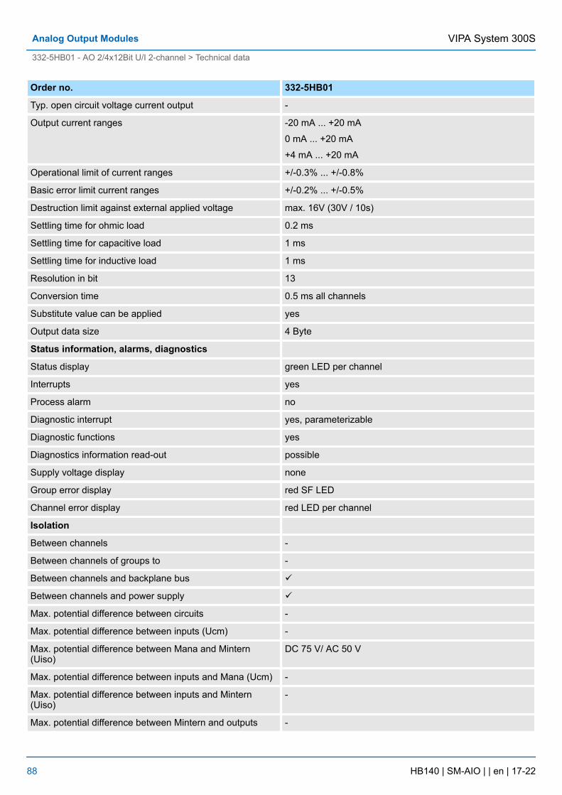
Order no. 332-5HB01
Typ. open circuit voltage current output -
Output current ranges -20 mA ... +20 mA
0 mA ... +20 mA
+4 mA ... +20 mA
Operational limit of current ranges +/-0.3% ... +/-0.8%
Basic error limit current ranges +/-0.2% ... +/-0.5%
Destruction limit against external applied voltage max. 16V (30V / 10s)
Settling time for ohmic load 0.2 ms
Settling time for capacitive load 1 ms
Settling time for inductive load 1 ms
Resolution in bit 13
Conversion time 0.5 ms all channels
Substitute value can be applied yes
Output data size 4 Byte
Status information, alarms, diagnostics
Status display green LED per channel
Interrupts yes
Process alarm no
Diagnostic interrupt yes, parameterizable
Diagnostic functions yes
Diagnostics information read-out possible
Supply voltage display none
Group error display red SF LED
Channel error display red LED per channel
Isolation
Between channels -
Between channels of groups to -
Between channels and backplane bus ü
Between channels and power supply ü
Max. potential difference between circuits -
Max. potential difference between inputs (Ucm) -
Max. potential difference between Mana and Mintern(Uiso)
DC 75 V/ AC 50 V
Max. potential difference between inputs and Mana (Ucm) -
Max. potential difference between inputs and Mintern(Uiso)
-
Max. potential difference between Mintern and outputs -
VIPA System 300SAnalog Output Modules
332-5HB01 - AO 2/4x12Bit U/I 2-channel > Technical data
HB140 | SM-AIO | | en | 17-22 88
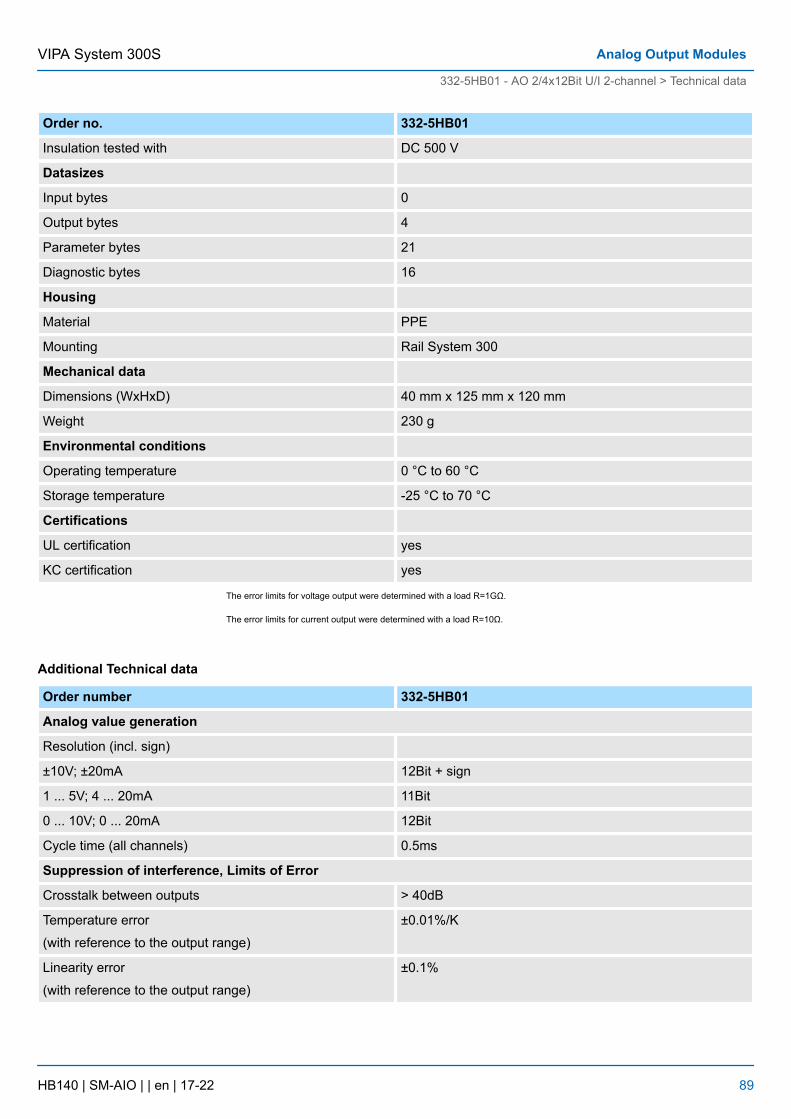
Order no. 332-5HB01
Insulation tested with DC 500 V
Datasizes
Input bytes 0
Output bytes 4
Parameter bytes 21
Diagnostic bytes 16
Housing
Material PPE
Mounting Rail System 300
Mechanical data
Dimensions (WxHxD) 40 mm x 125 mm x 120 mm
Weight 230 g
Environmental conditions
Operating temperature 0 °C to 60 °C
Storage temperature -25 °C to 70 °C
Certifications
UL certification yes
KC certification yes
The error limits for voltage output were determined with a load R=1GΩ.
The error limits for current output were determined with a load R=10Ω.
Additional Technical data
Order number 332-5HB01
Analog value generation
Resolution (incl. sign)
±10V; ±20mA 12Bit + sign
1 ... 5V; 4 ... 20mA 11Bit
0 ... 10V; 0 ... 20mA 12Bit
Cycle time (all channels) 0.5ms
Suppression of interference, Limits of Error
Crosstalk between outputs > 40dB
Temperature error
(with reference to the output range)
±0.01%/K
Linearity error
(with reference to the output range)
±0.1%
VIPA System 300S Analog Output Modules
332-5HB01 - AO 2/4x12Bit U/I 2-channel > Technical data
HB140 | SM-AIO | | en | 17-22 89
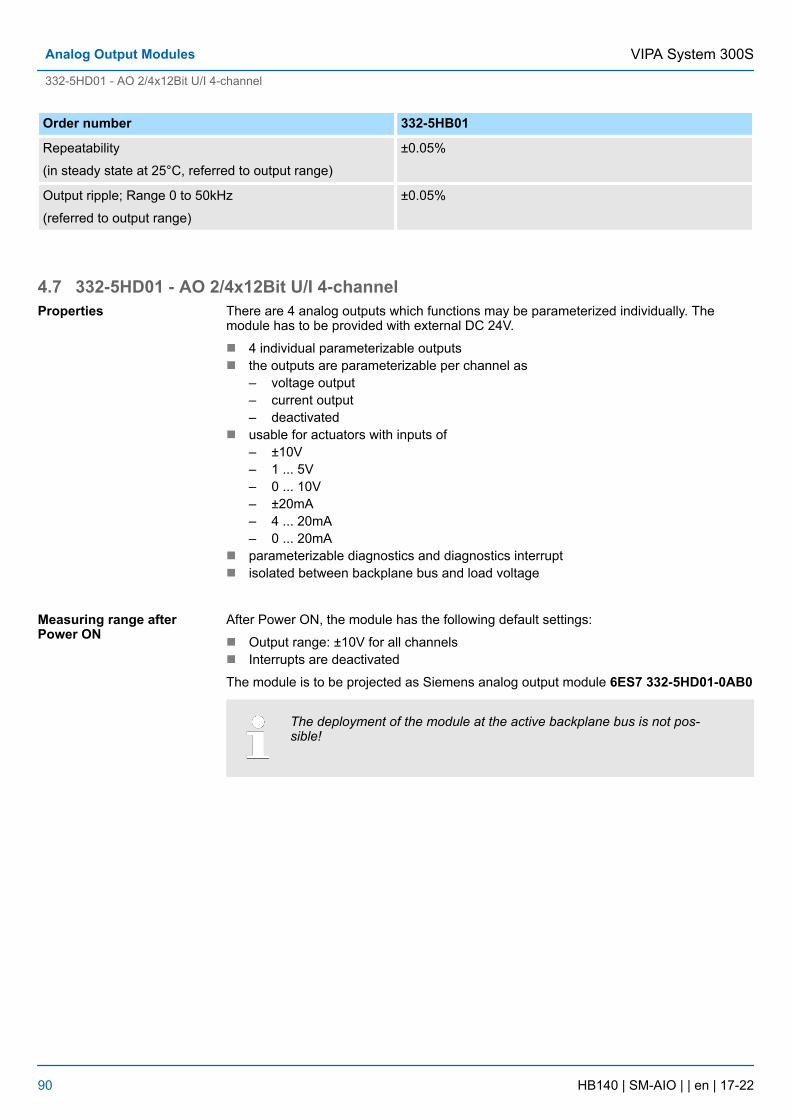
Order number 332-5HB01
Repeatability
(in steady state at 25°C, referred to output range)
±0.05%
Output ripple; Range 0 to 50kHz
(referred to output range)
±0.05%
4.7 332-5HD01 - AO 2/4x12Bit U/I 4-channelThere are 4 analog outputs which functions may be parameterized individually. Themodule has to be provided with external DC 24V.
n 4 individual parameterizable outputsn the outputs are parameterizable per channel as
– voltage output– current output– deactivated
n usable for actuators with inputs of– ±10V– 1 ... 5V– 0 ... 10V– ±20mA– 4 ... 20mA– 0 ... 20mA
n parameterizable diagnostics and diagnostics interruptn isolated between backplane bus and load voltage
After Power ON, the module has the following default settings:
n Output range: ±10V for all channelsn Interrupts are deactivated
The module is to be projected as Siemens analog output module 6ES7 332-5HD01-0AB0
The deployment of the module at the active backplane bus is not pos-sible!
Properties
Measuring range afterPower ON
VIPA System 300SAnalog Output Modules
332-5HD01 - AO 2/4x12Bit U/I 4-channel
HB140 | SM-AIO | | en | 17-22 90
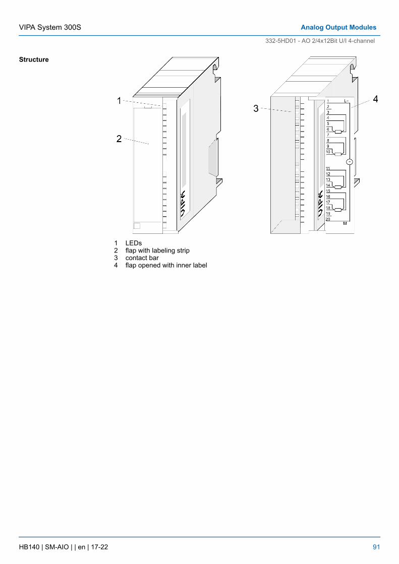
1 LEDs2 flap with labeling strip3 contact bar4 flap opened with inner label
Structure
VIPA System 300S Analog Output Modules
332-5HD01 - AO 2/4x12Bit U/I 4-channel
HB140 | SM-AIO | | en | 17-22 91
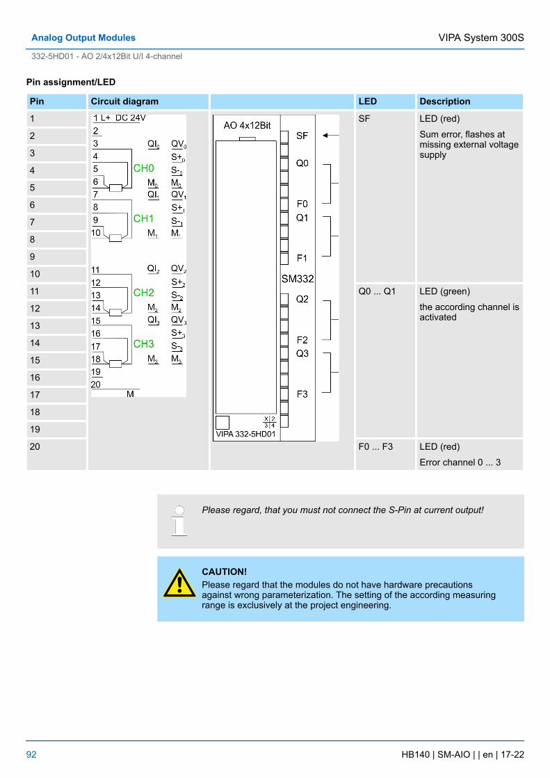
Pin assignment/LED
Pin Circuit diagram LED Description
1 SF LED (red)
Sum error, flashes atmissing external voltagesupply
2
3
4
5
6
7
8
9
10
11 Q0 ... Q1 LED (green)
the according channel isactivated
12
13
14
15
16
17
18
19
20 F0 ... F3 LED (red)
Error channel 0 ... 3
Please regard, that you must not connect the S-Pin at current output!
CAUTION!Please regard that the modules do not have hardware precautionsagainst wrong parameterization. The setting of the according measuringrange is exclusively at the project engineering.
VIPA System 300SAnalog Output Modules
332-5HD01 - AO 2/4x12Bit U/I 4-channel
HB140 | SM-AIO | | en | 17-22 92
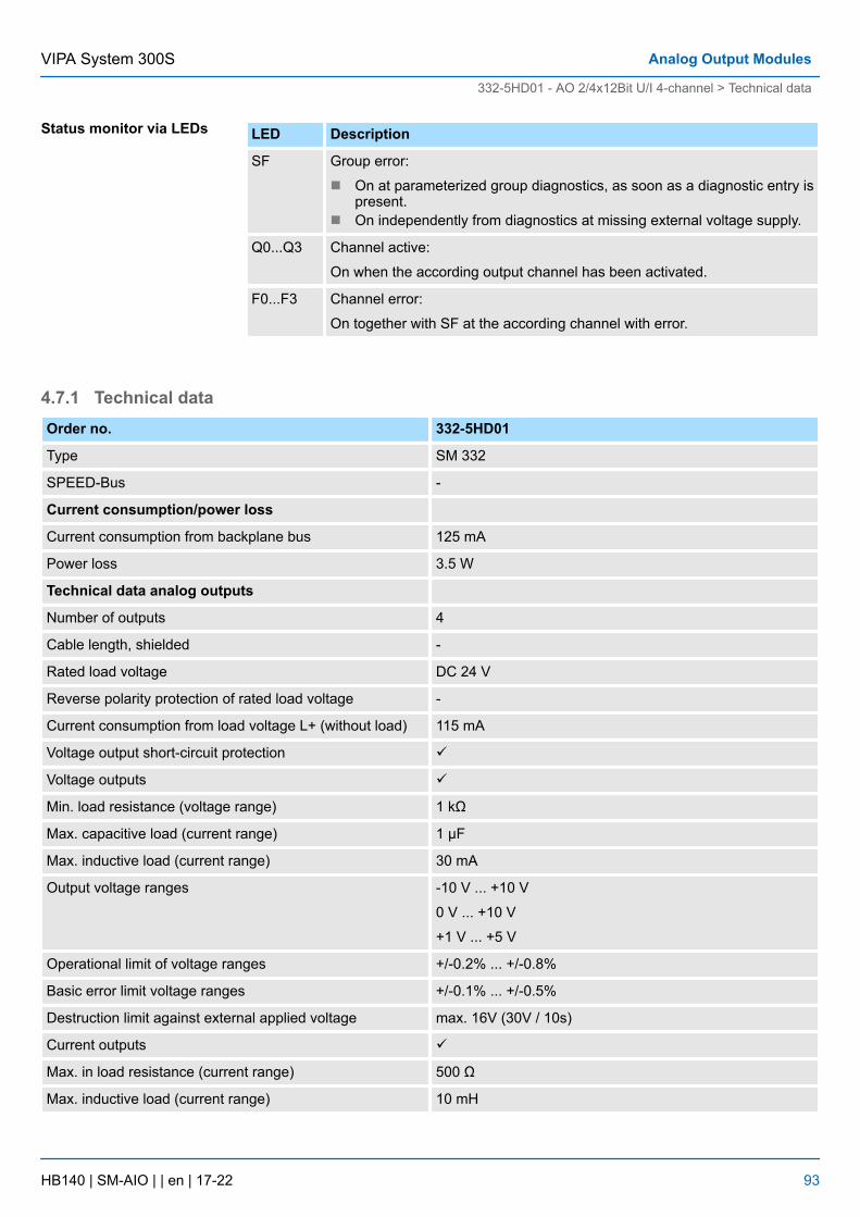
LED Description
SF Group error:
n On at parameterized group diagnostics, as soon as a diagnostic entry ispresent.
n On independently from diagnostics at missing external voltage supply.
Q0...Q3 Channel active:
On when the according output channel has been activated.
F0...F3 Channel error:
On together with SF at the according channel with error.
4.7.1 Technical dataOrder no. 332-5HD01
Type SM 332
SPEED-Bus -
Current consumption/power loss
Current consumption from backplane bus 125 mA
Power loss 3.5 W
Technical data analog outputs
Number of outputs 4
Cable length, shielded -
Rated load voltage DC 24 V
Reverse polarity protection of rated load voltage -
Current consumption from load voltage L+ (without load) 115 mA
Voltage output short-circuit protection ü
Voltage outputs ü
Min. load resistance (voltage range) 1 kΩ
Max. capacitive load (current range) 1 µF
Max. inductive load (current range) 30 mA
Output voltage ranges -10 V ... +10 V
0 V ... +10 V
+1 V ... +5 V
Operational limit of voltage ranges +/-0.2% ... +/-0.8%
Basic error limit voltage ranges +/-0.1% ... +/-0.5%
Destruction limit against external applied voltage max. 16V (30V / 10s)
Current outputs ü
Max. in load resistance (current range) 500 Ω
Max. inductive load (current range) 10 mH
Status monitor via LEDs
VIPA System 300S Analog Output Modules
332-5HD01 - AO 2/4x12Bit U/I 4-channel > Technical data
HB140 | SM-AIO | | en | 17-22 93

Order no. 332-5HD01
Typ. open circuit voltage current output -
Output current ranges -20 mA ... +20 mA
0 mA ... +20 mA
+4 mA ... +20 mA
Operational limit of current ranges +/-0.3% ... +/-0.8%
Basic error limit current ranges +/-0.2% ... +/-0.5%
Destruction limit against external applied voltage max. 16V (30V / 10s)
Settling time for ohmic load 0.2 ms
Settling time for capacitive load 1 ms
Settling time for inductive load 1 ms
Resolution in bit 13
Conversion time 1 ms all channels
Substitute value can be applied yes
Output data size 8 Byte
Status information, alarms, diagnostics
Status display green LED per channel
Interrupts yes
Process alarm no
Diagnostic interrupt yes, parameterizable
Diagnostic functions yes
Diagnostics information read-out possible
Supply voltage display none
Group error display red SF LED
Channel error display red LED per channel
Isolation
Between channels -
Between channels of groups to -
Between channels and backplane bus ü
Between channels and power supply ü
Max. potential difference between circuits -
Max. potential difference between inputs (Ucm) -
Max. potential difference between Mana and Mintern(Uiso)
DC 75 V/ AC 50 V
Max. potential difference between inputs and Mana (Ucm) -
Max. potential difference between inputs and Mintern(Uiso)
-
Max. potential difference between Mintern and outputs -
VIPA System 300SAnalog Output Modules
332-5HD01 - AO 2/4x12Bit U/I 4-channel > Technical data
HB140 | SM-AIO | | en | 17-22 94
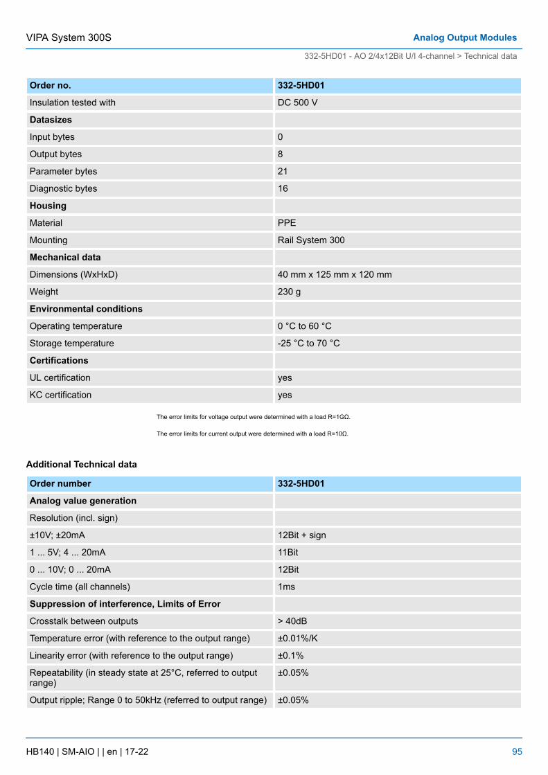
Order no. 332-5HD01
Insulation tested with DC 500 V
Datasizes
Input bytes 0
Output bytes 8
Parameter bytes 21
Diagnostic bytes 16
Housing
Material PPE
Mounting Rail System 300
Mechanical data
Dimensions (WxHxD) 40 mm x 125 mm x 120 mm
Weight 230 g
Environmental conditions
Operating temperature 0 °C to 60 °C
Storage temperature -25 °C to 70 °C
Certifications
UL certification yes
KC certification yes
The error limits for voltage output were determined with a load R=1GΩ.
The error limits for current output were determined with a load R=10Ω.
Additional Technical data
Order number 332-5HD01
Analog value generation
Resolution (incl. sign)
±10V; ±20mA 12Bit + sign
1 ... 5V; 4 ... 20mA 11Bit
0 ... 10V; 0 ... 20mA 12Bit
Cycle time (all channels) 1ms
Suppression of interference, Limits of Error
Crosstalk between outputs > 40dB
Temperature error (with reference to the output range) ±0.01%/K
Linearity error (with reference to the output range) ±0.1%
Repeatability (in steady state at 25°C, referred to outputrange)
±0.05%
Output ripple; Range 0 to 50kHz (referred to output range) ±0.05%
VIPA System 300S Analog Output Modules
332-5HD01 - AO 2/4x12Bit U/I 4-channel > Technical data
HB140 | SM-AIO | | en | 17-22 95
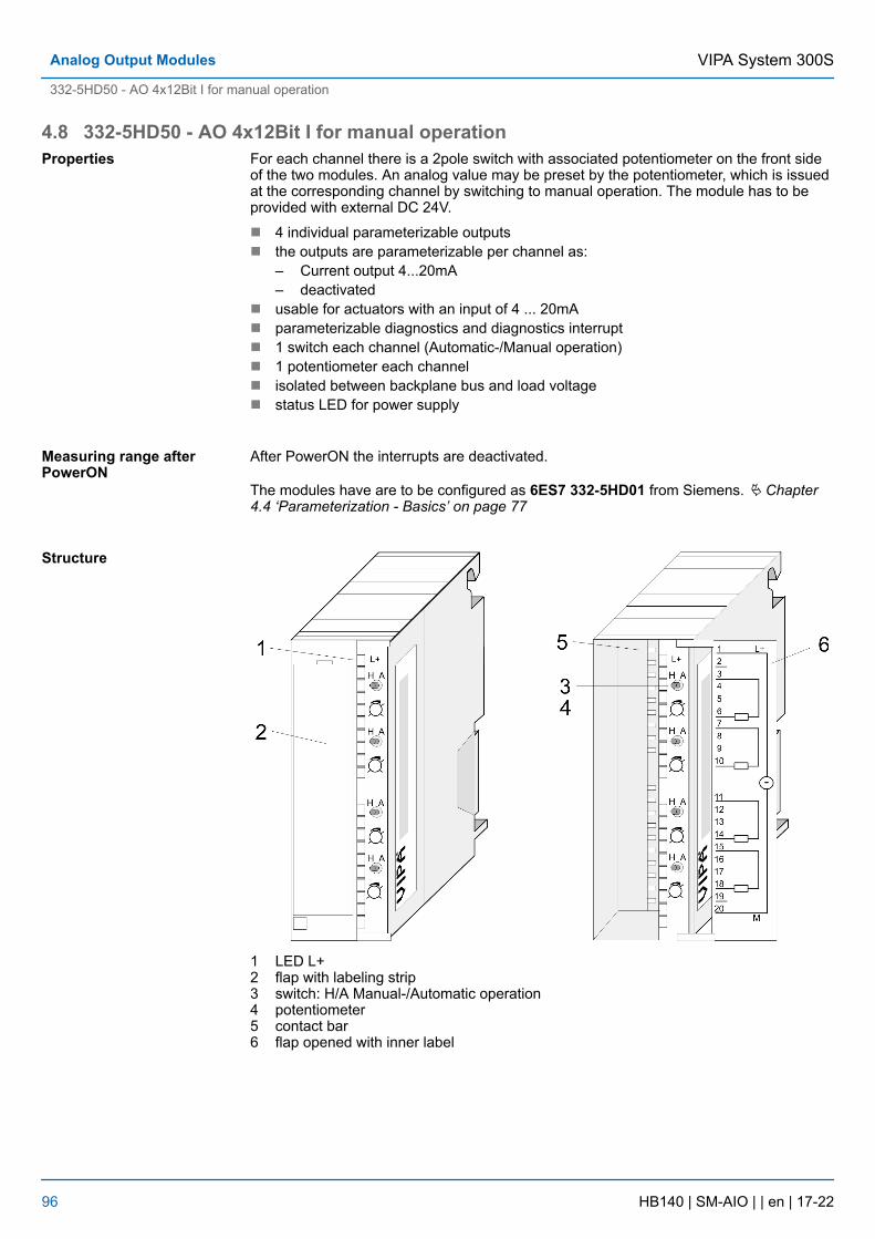
4.8 332-5HD50 - AO 4x12Bit I for manual operationFor each channel there is a 2pole switch with associated potentiometer on the front sideof the two modules. An analog value may be preset by the potentiometer, which is issuedat the corresponding channel by switching to manual operation. The module has to beprovided with external DC 24V.
n 4 individual parameterizable outputsn the outputs are parameterizable per channel as:
– Current output 4...20mA– deactivated
n usable for actuators with an input of 4 ... 20mAn parameterizable diagnostics and diagnostics interruptn 1 switch each channel (Automatic-/Manual operation)n 1 potentiometer each channeln isolated between backplane bus and load voltagen status LED for power supply
After PowerON the interrupts are deactivated.
The modules have are to be configured as 6ES7 332-5HD01 from Siemens. Ä Chapter4.4 ‘Parameterization - Basics’ on page 77
1 LED L+2 flap with labeling strip3 switch: H/A Manual-/Automatic operation4 potentiometer5 contact bar6 flap opened with inner label
Properties
Measuring range afterPowerON
Structure
VIPA System 300SAnalog Output Modules
332-5HD50 - AO 4x12Bit I for manual operation
HB140 | SM-AIO | | en | 17-22 96
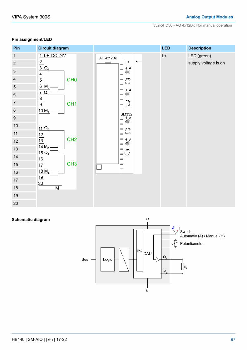
Pin assignment/LED
Pin Circuit diagram LED Description
1 L+ LED (green)
supply voltage is on2
3
4
5
6
7
8
9
10
11
12
13
14
15
16
17
18
19
20
Schematic diagram
VIPA System 300S Analog Output Modules
332-5HD50 - AO 4x12Bit I for manual operation
HB140 | SM-AIO | | en | 17-22 97
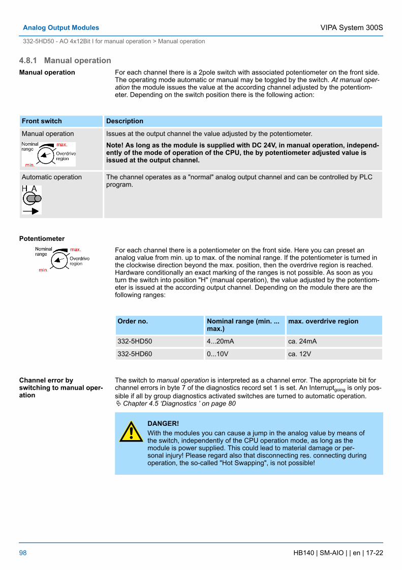
4.8.1 Manual operationFor each channel there is a 2pole switch with associated potentiometer on the front side.The operating mode automatic or manual may be toggled by the switch. At manual oper-ation the module issues the value at the according channel adjusted by the potentiom-eter. Depending on the switch position there is the following action:
Front switch Description
Manual operation Issues at the output channel the value adjusted by the potentiometer.
Note! As long as the module is supplied with DC 24V, in manual operation, independ-ently of the mode of operation of the CPU, the by potentiometer adjusted value isissued at the output channel.
Automatic operation The channel operates as a "normal" analog output channel and can be controlled by PLCprogram.
For each channel there is a potentiometer on the front side. Here you can preset ananalog value from min. up to max. of the nominal range. If the potentiometer is turned inthe clockwise direction beyond the max. position, then the overdrive region is reached.Hardware conditionally an exact marking of the ranges is not possible. As soon as youturn the switch into position "H" (manual operation), the value adjusted by the potentiom-eter is issued at the according output channel. Depending on the module there are thefollowing ranges:
Order no. Nominal range (min. ...max.)
max. overdrive region
332-5HD50 4...20mA ca. 24mA
332-5HD60 0...10V ca. 12V
The switch to manual operation is interpreted as a channel error. The appropriate bit forchannel errors in byte 7 of the diagnostics record set 1 is set. An Interruptgoing is only pos-sible if all by group diagnostics activated switches are turned to automatic operation.Ä Chapter 4.5 ‘Diagnostics ’ on page 80
DANGER!With the modules you can cause a jump in the analog value by means ofthe switch, independently of the CPU operation mode, as long as themodule is power supplied. This could lead to material damage or per-sonal injury! Please regard also that disconnecting res. connecting duringoperation, the so-called "Hot Swapping", is not possible!
Manual operation
Potentiometer
Channel error byswitching to manual oper-ation
VIPA System 300SAnalog Output Modules
332-5HD50 - AO 4x12Bit I for manual operation > Manual operation
HB140 | SM-AIO | | en | 17-22 98
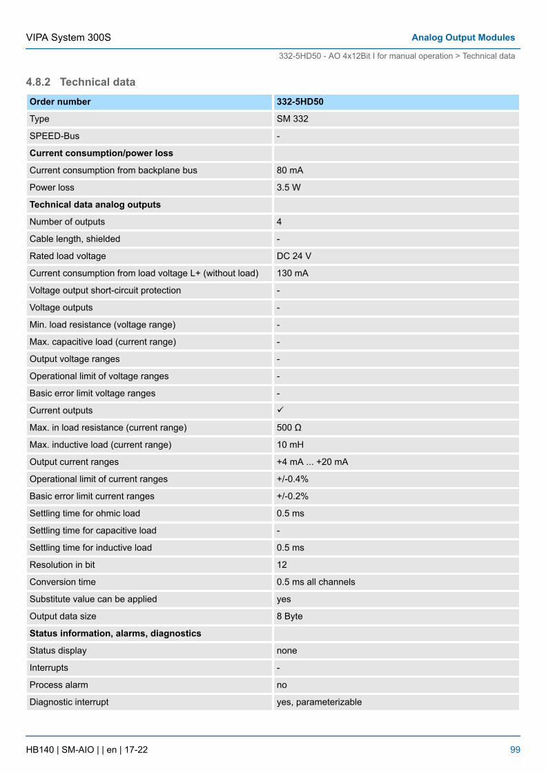
4.8.2 Technical dataOrder number 332-5HD50
Type SM 332
SPEED-Bus -
Current consumption/power loss
Current consumption from backplane bus 80 mA
Power loss 3.5 W
Technical data analog outputs
Number of outputs 4
Cable length, shielded -
Rated load voltage DC 24 V
Current consumption from load voltage L+ (without load) 130 mA
Voltage output short-circuit protection -
Voltage outputs -
Min. load resistance (voltage range) -
Max. capacitive load (current range) -
Output voltage ranges -
Operational limit of voltage ranges -
Basic error limit voltage ranges -
Current outputs ü
Max. in load resistance (current range) 500 Ω
Max. inductive load (current range) 10 mH
Output current ranges +4 mA ... +20 mA
Operational limit of current ranges +/-0.4%
Basic error limit current ranges +/-0.2%
Settling time for ohmic load 0.5 ms
Settling time for capacitive load -
Settling time for inductive load 0.5 ms
Resolution in bit 12
Conversion time 0.5 ms all channels
Substitute value can be applied yes
Output data size 8 Byte
Status information, alarms, diagnostics
Status display none
Interrupts -
Process alarm no
Diagnostic interrupt yes, parameterizable
VIPA System 300S Analog Output Modules
332-5HD50 - AO 4x12Bit I for manual operation > Technical data
HB140 | SM-AIO | | en | 17-22 99
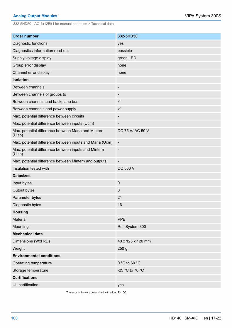
Order number 332-5HD50
Diagnostic functions yes
Diagnostics information read-out possible
Supply voltage display green LED
Group error display none
Channel error display none
Isolation
Between channels -
Between channels of groups to -
Between channels and backplane bus ü
Between channels and power supply ü
Max. potential difference between circuits -
Max. potential difference between inputs (Ucm) -
Max. potential difference between Mana and Mintern(Uiso)
DC 75 V/ AC 50 V
Max. potential difference between inputs and Mana (Ucm) -
Max. potential difference between inputs and Mintern(Uiso)
-
Max. potential difference between Mintern and outputs -
Insulation tested with DC 500 V
Datasizes
Input bytes 0
Output bytes 8
Parameter bytes 21
Diagnostic bytes 16
Housing
Material PPE
Mounting Rail System 300
Mechanical data
Dimensions (WxHxD) 40 x 125 x 120 mm
Weight 250 g
Environmental conditions
Operating temperature 0 °C to 60 °C
Storage temperature -25 °C to 70 °C
Certifications
UL certification yes
The error limits were determined with a load R=10Ω.
VIPA System 300SAnalog Output Modules
332-5HD50 - AO 4x12Bit I for manual operation > Technical data
HB140 | SM-AIO | | en | 17-22 100
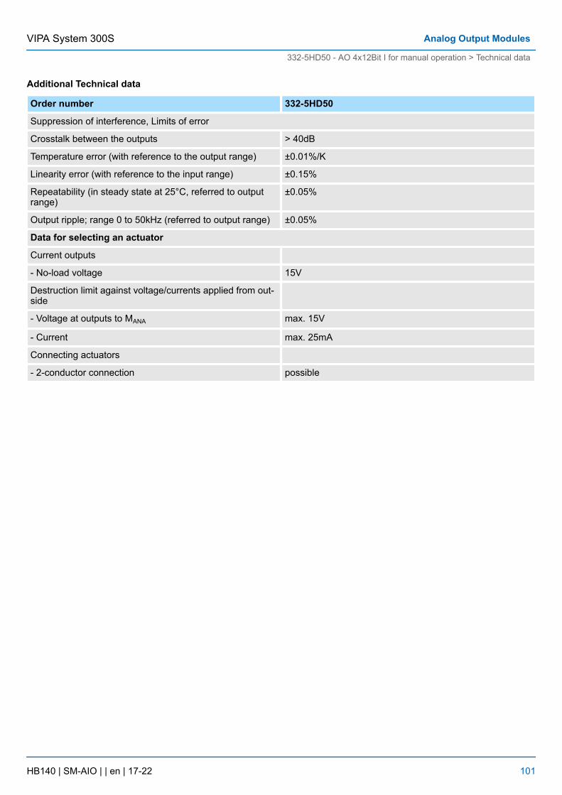
Additional Technical data
Order number 332-5HD50
Suppression of interference, Limits of error
Crosstalk between the outputs > 40dB
Temperature error (with reference to the output range) ±0.01%/K
Linearity error (with reference to the input range) ±0.15%
Repeatability (in steady state at 25°C, referred to outputrange)
±0.05%
Output ripple; range 0 to 50kHz (referred to output range) ±0.05%
Data for selecting an actuator
Current outputs
- No-load voltage 15V
Destruction limit against voltage/currents applied from out-side
- Voltage at outputs to MANA max. 15V
- Current max. 25mA
Connecting actuators
- 2-conductor connection possible
VIPA System 300S Analog Output Modules
332-5HD50 - AO 4x12Bit I for manual operation > Technical data
HB140 | SM-AIO | | en | 17-22 101
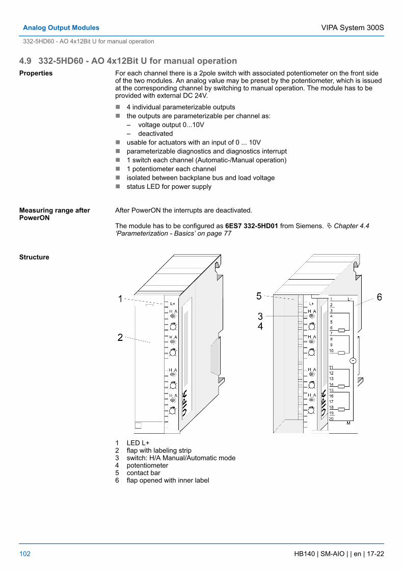
4.9 332-5HD60 - AO 4x12Bit U for manual operationFor each channel there is a 2pole switch with associated potentiometer on the front sideof the two modules. An analog value may be preset by the potentiometer, which is issuedat the corresponding channel by switching to manual operation. The module has to beprovided with external DC 24V.
n 4 individual parameterizable outputsn the outputs are parameterizable per channel as:
– voltage output 0...10V– deactivated
n usable for actuators with an input of 0 ... 10Vn parameterizable diagnostics and diagnostics interruptn 1 switch each channel (Automatic-/Manual operation)n 1 potentiometer each channeln isolated between backplane bus and load voltagen status LED for power supply
After PowerON the interrupts are deactivated.
The module has to be configured as 6ES7 332-5HD01 from Siemens. Ä Chapter 4.4‘Parameterization - Basics’ on page 77
1 LED L+2 flap with labeling strip3 switch: H/A Manual/Automatic mode4 potentiometer5 contact bar6 flap opened with inner label
Properties
Measuring range afterPowerON
Structure
VIPA System 300SAnalog Output Modules
332-5HD60 - AO 4x12Bit U for manual operation
HB140 | SM-AIO | | en | 17-22 102
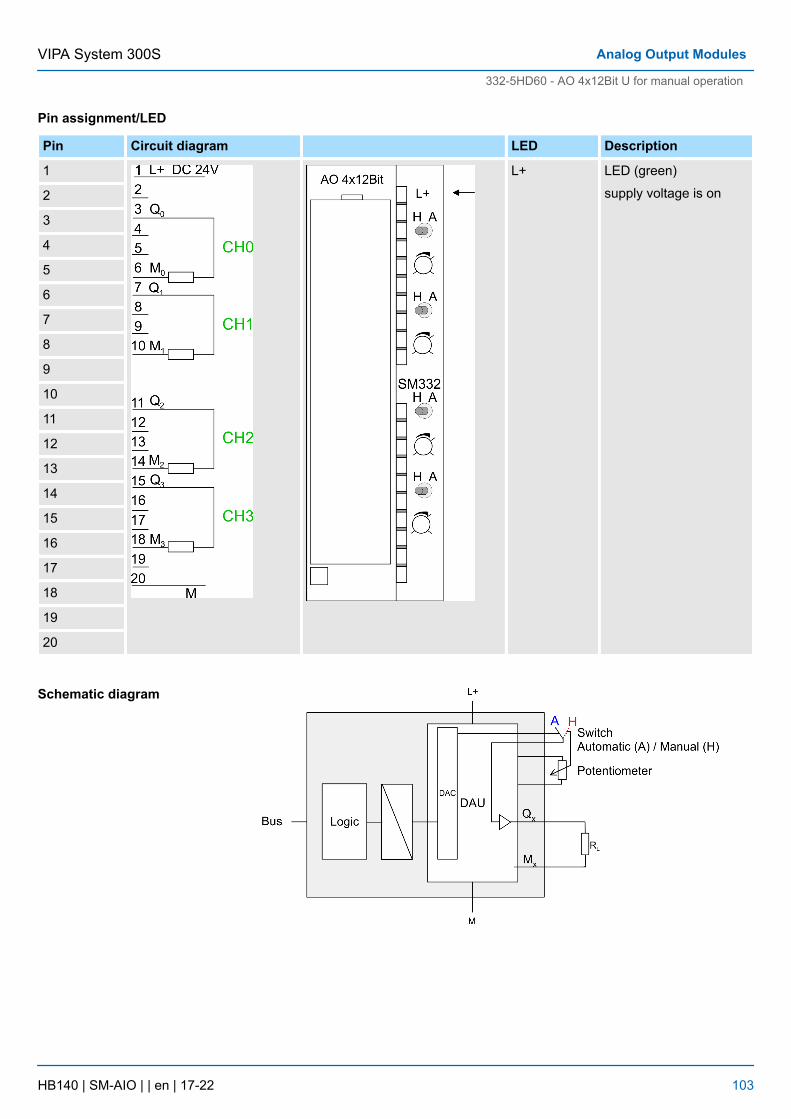
Pin assignment/LED
Pin Circuit diagram LED Description
1 L+ LED (green)
supply voltage is on2
3
4
5
6
7
8
9
10
11
12
13
14
15
16
17
18
19
20
Schematic diagram
VIPA System 300S Analog Output Modules
332-5HD60 - AO 4x12Bit U for manual operation
HB140 | SM-AIO | | en | 17-22 103
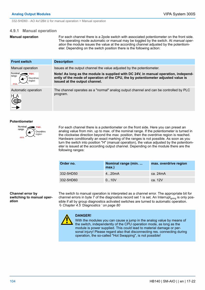
4.9.1 Manual operationFor each channel there is a 2pole switch with associated potentiometer on the front side.The operating mode automatic or manual may be toggled by the switch. At manual oper-ation the module issues the value at the according channel adjusted by the potentiom-eter. Depending on the switch position there is the following action:
Front switch Description
Manual operation Issues at the output channel the value adjusted by the potentiometer.
Note! As long as the module is supplied with DC 24V, in manual operation, independ-ently of the mode of operation of the CPU, the by potentiometer adjusted value isissued at the output channel.
Automatic operation The channel operates as a "normal" analog output channel and can be controlled by PLCprogram.
For each channel there is a potentiometer on the front side. Here you can preset ananalog value from min. up to max. of the nominal range. If the potentiometer is turned inthe clockwise direction beyond the max. position, then the overdrive region is reached.Hardware conditionally an exact marking of the ranges is not possible. As soon as youturn the switch into position "H" (manual operation), the value adjusted by the potentiom-eter is issued at the according output channel. Depending on the module there are thefollowing ranges:
Order no. Nominal range (min. ...max.)
max. overdrive region
332-5HD50 4...20mA ca. 24mA
332-5HD60 0...10V ca. 12V
The switch to manual operation is interpreted as a channel error. The appropriate bit forchannel errors in byte 7 of the diagnostics record set 1 is set. An Interruptgoing is only pos-sible if all by group diagnostics activated switches are turned to automatic operation.Ä Chapter 4.5 ‘Diagnostics ’ on page 80
DANGER!With the modules you can cause a jump in the analog value by means ofthe switch, independently of the CPU operation mode, as long as themodule is power supplied. This could lead to material damage or per-sonal injury! Please regard also that disconnecting res. connecting duringoperation, the so-called "Hot Swapping", is not possible!
Manual operation
Potentiometer
Channel error byswitching to manual oper-ation
VIPA System 300SAnalog Output Modules
332-5HD60 - AO 4x12Bit U for manual operation > Manual operation
HB140 | SM-AIO | | en | 17-22 104
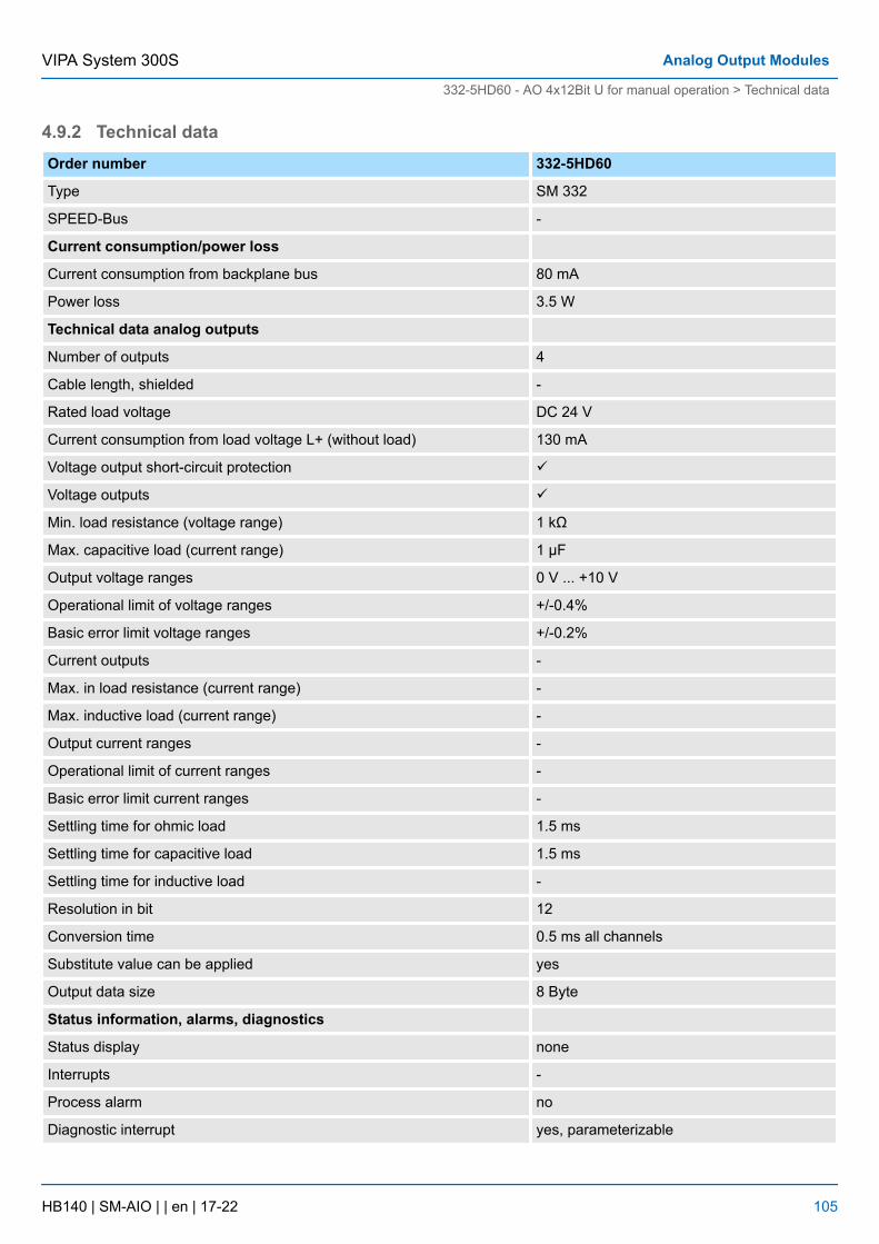
4.9.2 Technical dataOrder number 332-5HD60
Type SM 332
SPEED-Bus -
Current consumption/power loss
Current consumption from backplane bus 80 mA
Power loss 3.5 W
Technical data analog outputs
Number of outputs 4
Cable length, shielded -
Rated load voltage DC 24 V
Current consumption from load voltage L+ (without load) 130 mA
Voltage output short-circuit protection ü
Voltage outputs ü
Min. load resistance (voltage range) 1 kΩ
Max. capacitive load (current range) 1 µF
Output voltage ranges 0 V ... +10 V
Operational limit of voltage ranges +/-0.4%
Basic error limit voltage ranges +/-0.2%
Current outputs -
Max. in load resistance (current range) -
Max. inductive load (current range) -
Output current ranges -
Operational limit of current ranges -
Basic error limit current ranges -
Settling time for ohmic load 1.5 ms
Settling time for capacitive load 1.5 ms
Settling time for inductive load -
Resolution in bit 12
Conversion time 0.5 ms all channels
Substitute value can be applied yes
Output data size 8 Byte
Status information, alarms, diagnostics
Status display none
Interrupts -
Process alarm no
Diagnostic interrupt yes, parameterizable
VIPA System 300S Analog Output Modules
332-5HD60 - AO 4x12Bit U for manual operation > Technical data
HB140 | SM-AIO | | en | 17-22 105
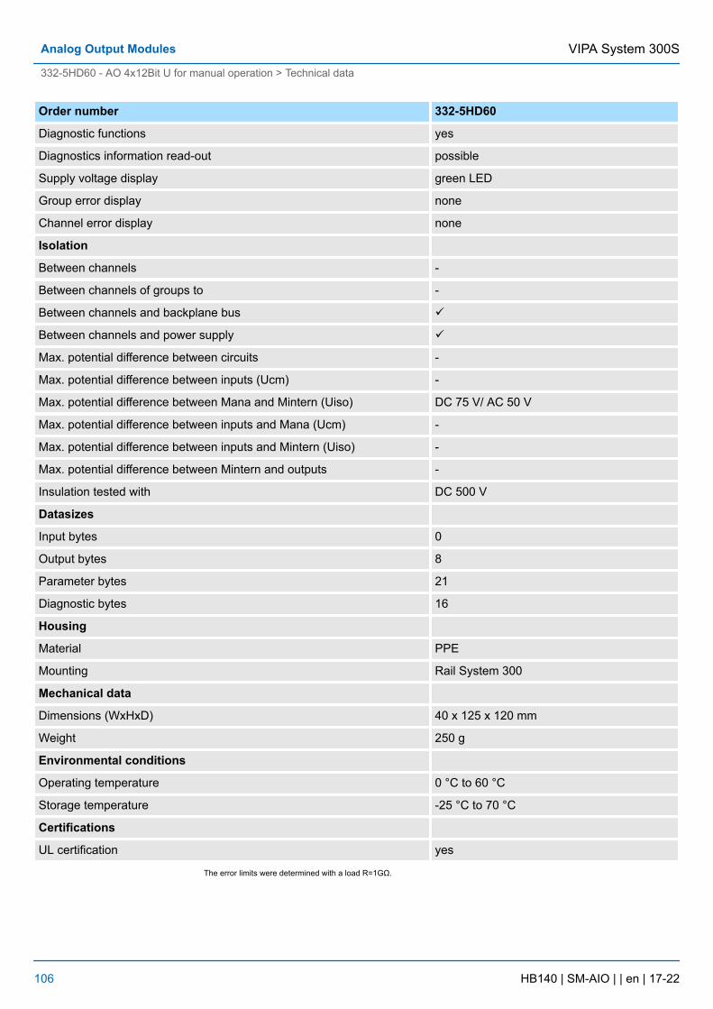
Order number 332-5HD60
Diagnostic functions yes
Diagnostics information read-out possible
Supply voltage display green LED
Group error display none
Channel error display none
Isolation
Between channels -
Between channels of groups to -
Between channels and backplane bus ü
Between channels and power supply ü
Max. potential difference between circuits -
Max. potential difference between inputs (Ucm) -
Max. potential difference between Mana and Mintern (Uiso) DC 75 V/ AC 50 V
Max. potential difference between inputs and Mana (Ucm) -
Max. potential difference between inputs and Mintern (Uiso) -
Max. potential difference between Mintern and outputs -
Insulation tested with DC 500 V
Datasizes
Input bytes 0
Output bytes 8
Parameter bytes 21
Diagnostic bytes 16
Housing
Material PPE
Mounting Rail System 300
Mechanical data
Dimensions (WxHxD) 40 x 125 x 120 mm
Weight 250 g
Environmental conditions
Operating temperature 0 °C to 60 °C
Storage temperature -25 °C to 70 °C
Certifications
UL certification yes
The error limits were determined with a load R=1GΩ.
VIPA System 300SAnalog Output Modules
332-5HD60 - AO 4x12Bit U for manual operation > Technical data
HB140 | SM-AIO | | en | 17-22 106
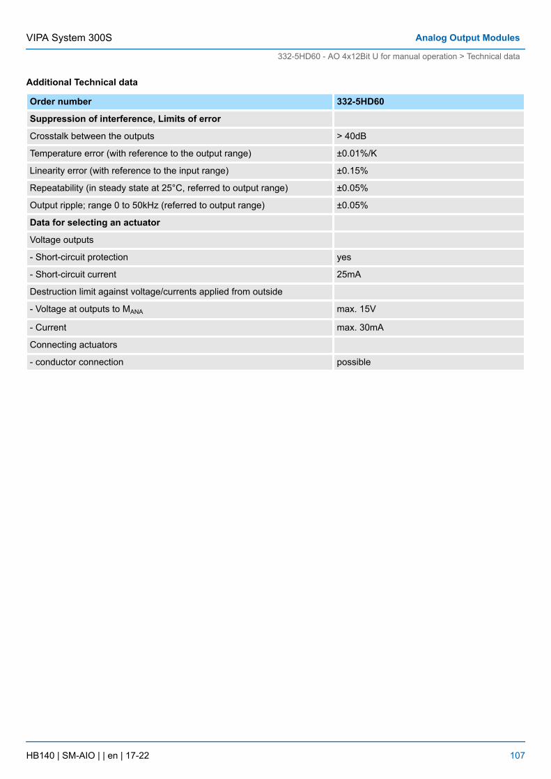
Additional Technical data
Order number 332-5HD60
Suppression of interference, Limits of error
Crosstalk between the outputs > 40dB
Temperature error (with reference to the output range) ±0.01%/K
Linearity error (with reference to the input range) ±0.15%
Repeatability (in steady state at 25°C, referred to output range) ±0.05%
Output ripple; range 0 to 50kHz (referred to output range) ±0.05%
Data for selecting an actuator
Voltage outputs
- Short-circuit protection yes
- Short-circuit current 25mA
Destruction limit against voltage/currents applied from outside
- Voltage at outputs to MANA max. 15V
- Current max. 30mA
Connecting actuators
- conductor connection possible
VIPA System 300S Analog Output Modules
332-5HD60 - AO 4x12Bit U for manual operation > Technical data
HB140 | SM-AIO | | en | 17-22 107
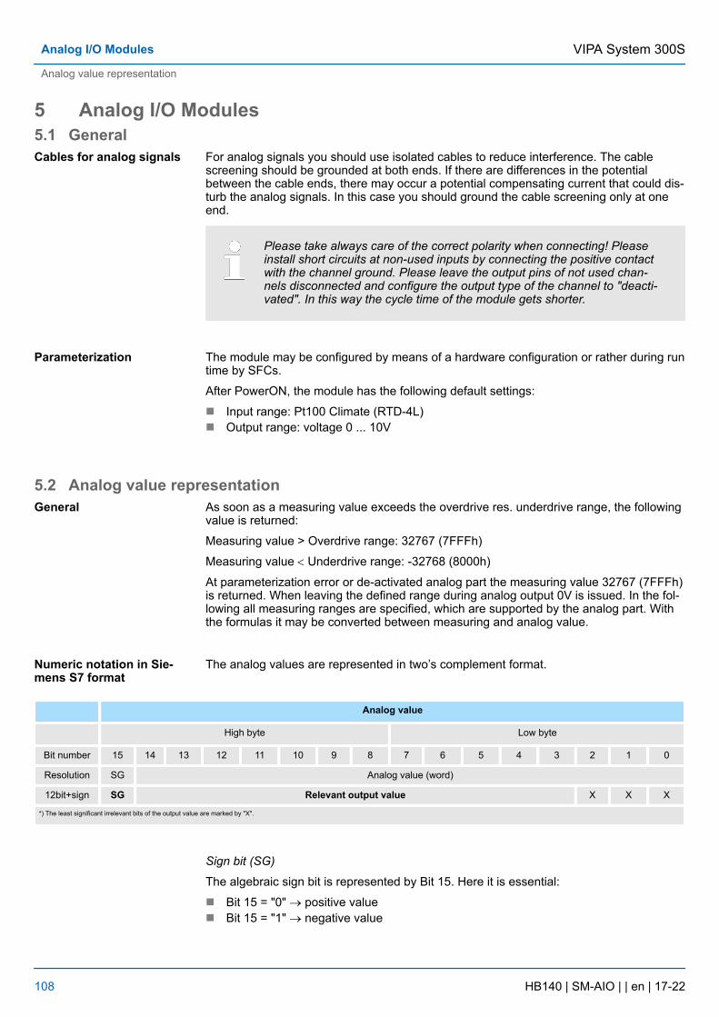
5 Analog I/O Modules5.1 General
For analog signals you should use isolated cables to reduce interference. The cablescreening should be grounded at both ends. If there are differences in the potentialbetween the cable ends, there may occur a potential compensating current that could dis-turb the analog signals. In this case you should ground the cable screening only at oneend.
Please take always care of the correct polarity when connecting! Pleaseinstall short circuits at non-used inputs by connecting the positive contactwith the channel ground. Please leave the output pins of not used chan-nels disconnected and configure the output type of the channel to "deacti-vated". In this way the cycle time of the module gets shorter.
The module may be configured by means of a hardware configuration or rather during runtime by SFCs.
After PowerON, the module has the following default settings:
n Input range: Pt100 Climate (RTD-4L)n Output range: voltage 0 ... 10V
5.2 Analog value representationAs soon as a measuring value exceeds the overdrive res. underdrive range, the followingvalue is returned:
Measuring value > Overdrive range: 32767 (7FFFh)
Measuring value < Underdrive range: -32768 (8000h)
At parameterization error or de-activated analog part the measuring value 32767 (7FFFh)is returned. When leaving the defined range during analog output 0V is issued. In the fol-lowing all measuring ranges are specified, which are supported by the analog part. Withthe formulas it may be converted between measuring and analog value.
The analog values are represented in two’s complement format.
Analog value
High byte Low byte
Bit number 15 14 13 12 11 10 9 8 7 6 5 4 3 2 1 0
Resolution SG Analog value (word)
12bit+sign SG Relevant output value X X X
*) The least significant irrelevant bits of the output value are marked by "X".
Sign bit (SG)
The algebraic sign bit is represented by Bit 15. Here it is essential:
n Bit 15 = "0" ® positive valuen Bit 15 = "1" ® negative value
Cables for analog signals
Parameterization
General
Numeric notation in Sie-mens S7 format
VIPA System 300SAnalog I/O Modules
Analog value representation
HB140 | SM-AIO | | en | 17-22 108
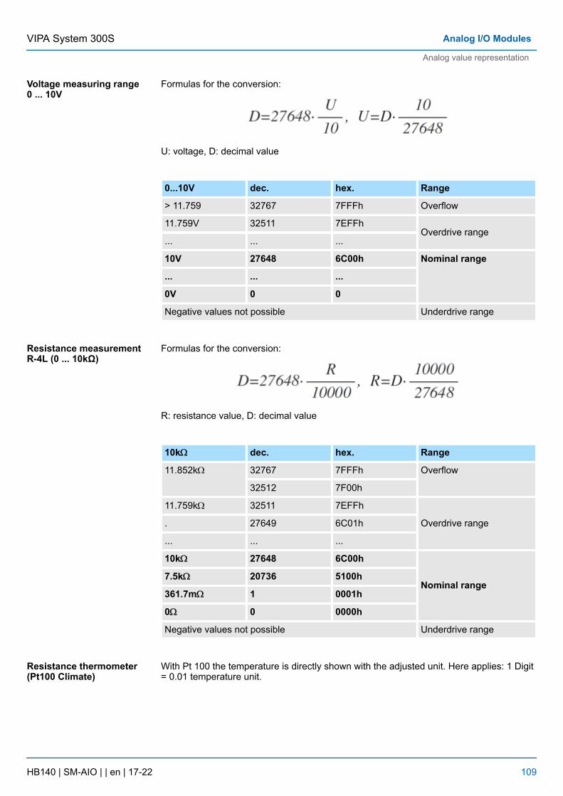
Formulas for the conversion:
U: voltage, D: decimal value
0...10V dec. hex. Range
> 11.759 32767 7FFFh Overflow
11.759V 32511 7EFFhOverdrive range
... ... ...
10V 27648 6C00h Nominal range
... ... ...
0V 0 0
Negative values not possible Underdrive range
Formulas for the conversion:
R: resistance value, D: decimal value
10kW dec. hex. Range
11.852kW 32767 7FFFh Overflow
32512 7F00h
11.759kW 32511 7EFFh
Overdrive range. 27649 6C01h
... ... ...
10kW 27648 6C00h
Nominal range7.5kW 20736 5100h
361.7mW 1 0001h
0W 0 0000h
Negative values not possible Underdrive range
With Pt 100 the temperature is directly shown with the adjusted unit. Here applies: 1 Digit= 0.01 temperature unit.
Voltage measuring range0 ... 10V
Resistance measurementR-4L (0 ... 10kΩ)
Resistance thermometer(Pt100 Climate)
VIPA System 300S Analog I/O Modules
Analog value representation
HB140 | SM-AIO | | en | 17-22 109
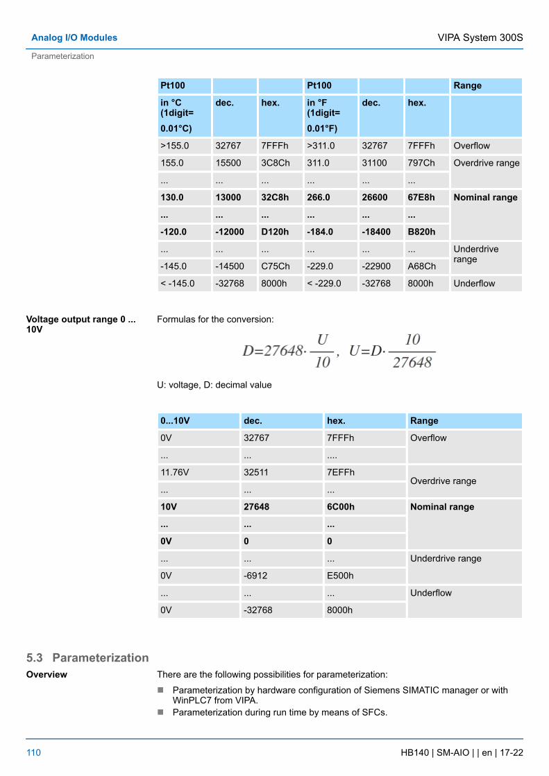
Pt100 Pt100 Range
in °C (1digit=0.01°C)
dec. hex. in °F(1digit=0.01°F)
dec. hex.
>155.0 32767 7FFFh >311.0 32767 7FFFh Overflow
155.0 15500 3C8Ch 311.0 31100 797Ch Overdrive range
... ... ... ... ... ...
130.0 13000 32C8h 266.0 26600 67E8h Nominal range
... ... ... ... ... ...
-120.0 -12000 D120h -184.0 -18400 B820h
... ... ... ... ... ... Underdriverange
-145.0 -14500 C75Ch -229.0 -22900 A68Ch
< -145.0 -32768 8000h < -229.0 -32768 8000h Underflow
Formulas for the conversion:
U: voltage, D: decimal value
0...10V dec. hex. Range
0V 32767 7FFFh Overflow
... ... ....
11.76V 32511 7EFFhOverdrive range
... ... ...
10V 27648 6C00h Nominal range
... ... ...
0V 0 0
... ... ... Underdrive range
0V -6912 E500h
... ... ... Underflow
0V -32768 8000h
5.3 ParameterizationThere are the following possibilities for parameterization:
n Parameterization by hardware configuration of Siemens SIMATIC manager or withWinPLC7 from VIPA.
n Parameterization during run time by means of SFCs.
Voltage output range 0 ...10V
Overview
VIPA System 300SAnalog I/O Modules
Parameterization
HB140 | SM-AIO | | en | 17-22 110
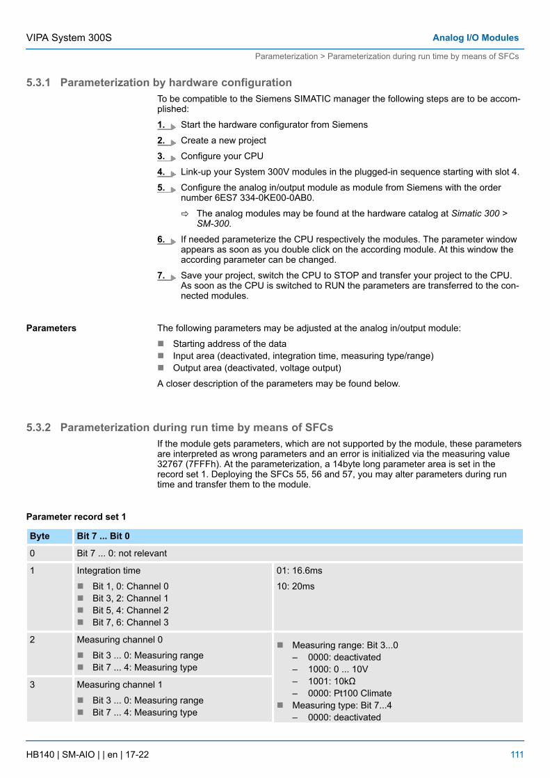
5.3.1 Parameterization by hardware configurationTo be compatible to the Siemens SIMATIC manager the following steps are to be accom-plished:
1. Start the hardware configurator from Siemens
2. Create a new project
3. Configure your CPU
4. Link-up your System 300V modules in the plugged-in sequence starting with slot 4.
5. Configure the analog in/output module as module from Siemens with the ordernumber 6ES7 334-0KE00-0AB0.
ð The analog modules may be found at the hardware catalog at Simatic 300 >SM-300.
6. If needed parameterize the CPU respectively the modules. The parameter windowappears as soon as you double click on the according module. At this window theaccording parameter can be changed.
7. Save your project, switch the CPU to STOP and transfer your project to the CPU.As soon as the CPU is switched to RUN the parameters are transferred to the con-nected modules.
The following parameters may be adjusted at the analog in/output module:
n Starting address of the datan Input area (deactivated, integration time, measuring type/range)n Output area (deactivated, voltage output)
A closer description of the parameters may be found below.
5.3.2 Parameterization during run time by means of SFCsIf the module gets parameters, which are not supported by the module, these parametersare interpreted as wrong parameters and an error is initialized via the measuring value32767 (7FFFh). At the parameterization, a 14byte long parameter area is set in therecord set 1. Deploying the SFCs 55, 56 and 57, you may alter parameters during runtime and transfer them to the module.
Byte Bit 7 ... Bit 0
0 Bit 7 ... 0: not relevant
1 Integration time
n Bit 1, 0: Channel 0n Bit 3, 2: Channel 1n Bit 5, 4: Channel 2n Bit 7, 6: Channel 3
01: 16.6ms
10: 20ms
2 Measuring channel 0
n Bit 3 ... 0: Measuring rangen Bit 7 ... 4: Measuring type
n Measuring range: Bit 3...0– 0000: deactivated– 1000: 0 ... 10V– 1001: 10kΩ– 0000: Pt100 Climate
n Measuring type: Bit 7...4– 0000: deactivated
3 Measuring channel 1
n Bit 3 ... 0: Measuring rangen Bit 7 ... 4: Measuring type
Parameters
Parameter record set 1
VIPA System 300S Analog I/O Modules
Parameterization > Parameterization during run time by means of SFCs
HB140 | SM-AIO | | en | 17-22 111
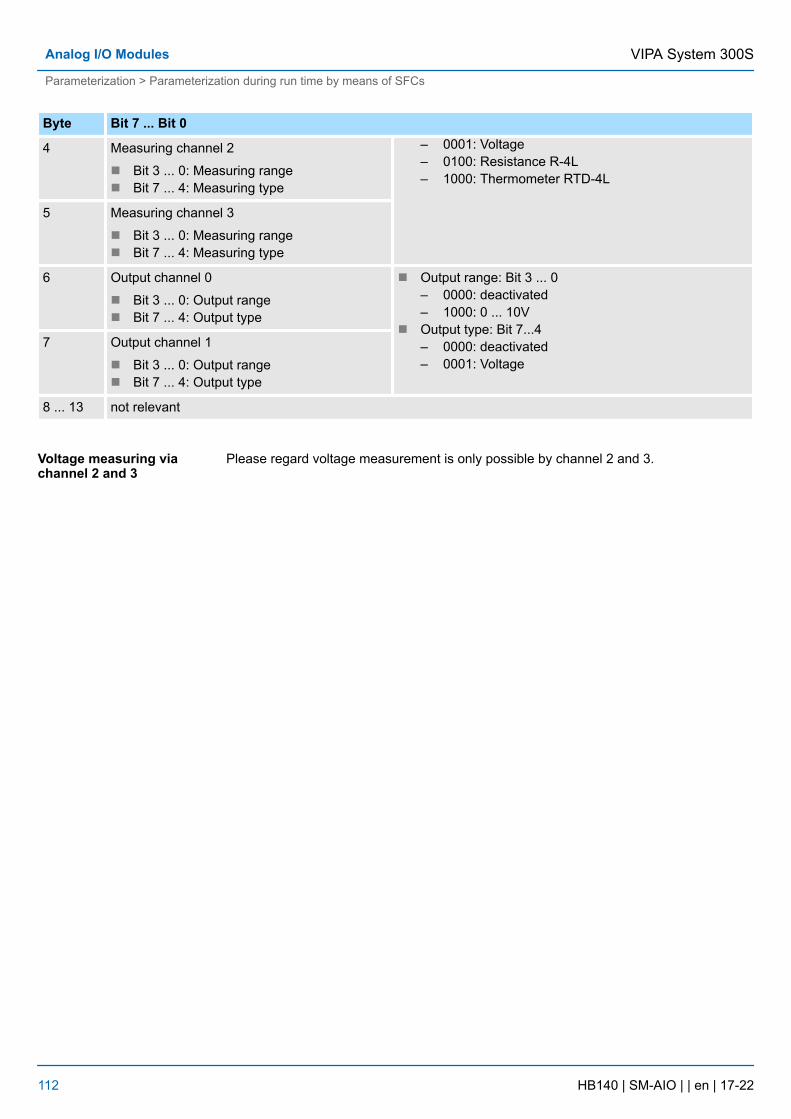
Byte Bit 7 ... Bit 0
4 – 0001: Voltage– 0100: Resistance R-4L– 1000: Thermometer RTD-4L
Measuring channel 2
n Bit 3 ... 0: Measuring rangen Bit 7 ... 4: Measuring type
5 Measuring channel 3
n Bit 3 ... 0: Measuring rangen Bit 7 ... 4: Measuring type
6 Output channel 0
n Bit 3 ... 0: Output rangen Bit 7 ... 4: Output type
n Output range: Bit 3 ... 0– 0000: deactivated– 1000: 0 ... 10V
n Output type: Bit 7...4– 0000: deactivated– 0001: Voltage
7 Output channel 1
n Bit 3 ... 0: Output rangen Bit 7 ... 4: Output type
8 ... 13 not relevant
Please regard voltage measurement is only possible by channel 2 and 3.Voltage measuring viachannel 2 and 3
VIPA System 300SAnalog I/O Modules
Parameterization > Parameterization during run time by means of SFCs
HB140 | SM-AIO | | en | 17-22 112
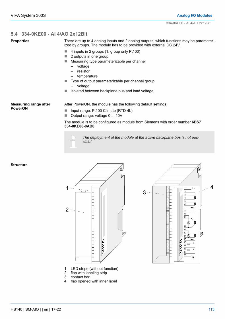
5.4 334-0KE00 - AI 4/AO 2x12BitThere are up to 4 analog inputs and 2 analog outputs, which functions may be parameter-ized by groups. The module has to be provided with external DC 24V.
n 4 inputs in 2 groups (1. group only Pt100)n 2 outputs in one groupn Measuring type parameterizable per channel
– voltage– resistor– temperature
n Type of output parameterizable per channel group– voltage
n isolated between backplane bus and load voltage
After PowerON, the module has the following default settings:
n Input range: Pt100 Climate (RTD-4L)n Output range: voltage 0 ... 10V
The module is to be configured as module from Siemens with order number 6ES7334-0KE00-0AB0.
The deployment of the module at the active backplane bus is not pos-sible!
1 LED stripe (without function)2 flap with labeling strip3 contact bar4 flap opened with inner label
Properties
Measuring range afterPowerON
Structure
VIPA System 300S Analog I/O Modules
334-0KE00 - AI 4/AO 2x12Bit
HB140 | SM-AIO | | en | 17-22 113
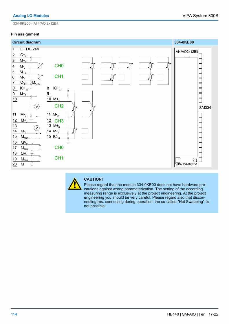
Pin assignment
Circuit diagram 334-0KE00
CAUTION!Please regard that the module 334-0KE00 does not have hardware pre-cautions against wrong parameterization. The setting of the accordingmeasuring range is exclusively at the project engineering. At the projectengineering you should be very careful. Please regard also that discon-necting res. connecting during operation, the so-called "Hot Swapping", isnot possible!
VIPA System 300SAnalog I/O Modules
334-0KE00 - AI 4/AO 2x12Bit
HB140 | SM-AIO | | en | 17-22 114
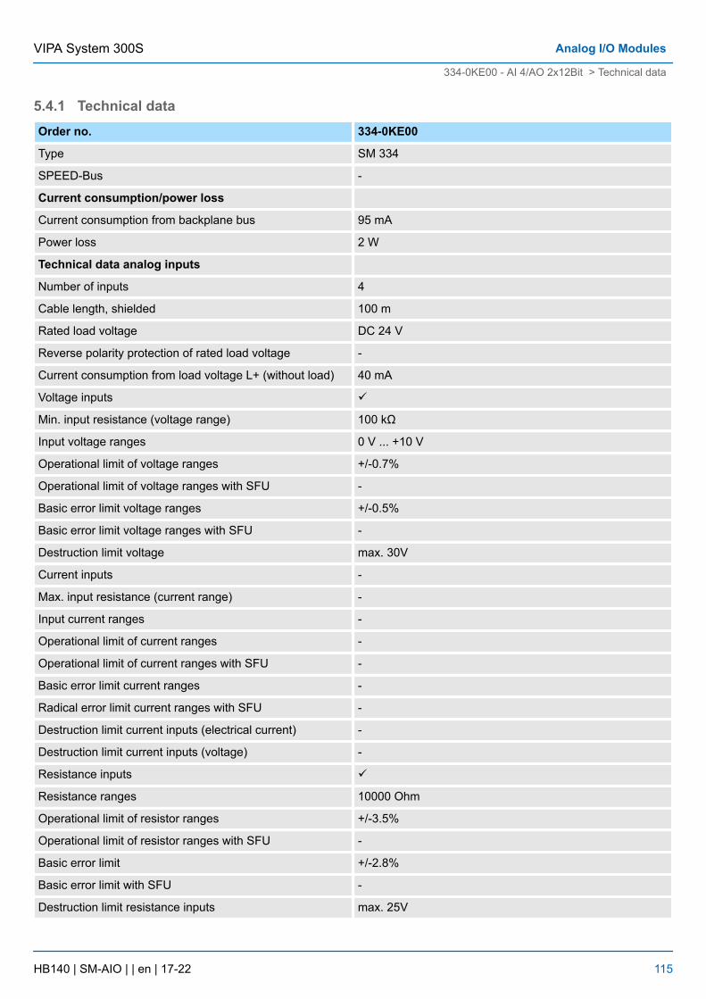
5.4.1 Technical dataOrder no. 334-0KE00
Type SM 334
SPEED-Bus -
Current consumption/power loss
Current consumption from backplane bus 95 mA
Power loss 2 W
Technical data analog inputs
Number of inputs 4
Cable length, shielded 100 m
Rated load voltage DC 24 V
Reverse polarity protection of rated load voltage -
Current consumption from load voltage L+ (without load) 40 mA
Voltage inputs ü
Min. input resistance (voltage range) 100 kΩ
Input voltage ranges 0 V ... +10 V
Operational limit of voltage ranges +/-0.7%
Operational limit of voltage ranges with SFU -
Basic error limit voltage ranges +/-0.5%
Basic error limit voltage ranges with SFU -
Destruction limit voltage max. 30V
Current inputs -
Max. input resistance (current range) -
Input current ranges -
Operational limit of current ranges -
Operational limit of current ranges with SFU -
Basic error limit current ranges -
Radical error limit current ranges with SFU -
Destruction limit current inputs (electrical current) -
Destruction limit current inputs (voltage) -
Resistance inputs ü
Resistance ranges 10000 Ohm
Operational limit of resistor ranges +/-3.5%
Operational limit of resistor ranges with SFU -
Basic error limit +/-2.8%
Basic error limit with SFU -
Destruction limit resistance inputs max. 25V
VIPA System 300S Analog I/O Modules
334-0KE00 - AI 4/AO 2x12Bit > Technical data
HB140 | SM-AIO | | en | 17-22 115
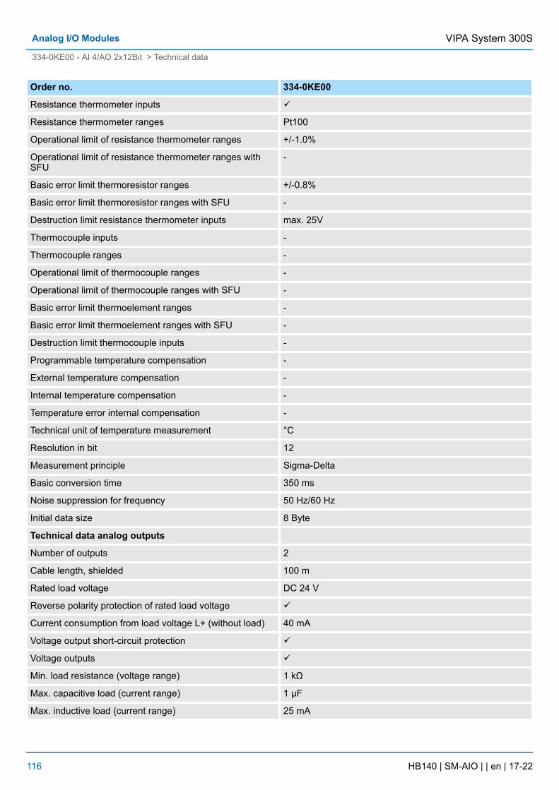
Order no. 334-0KE00
Resistance thermometer inputs ü
Resistance thermometer ranges Pt100
Operational limit of resistance thermometer ranges +/-1.0%
Operational limit of resistance thermometer ranges withSFU
-
Basic error limit thermoresistor ranges +/-0.8%
Basic error limit thermoresistor ranges with SFU -
Destruction limit resistance thermometer inputs max. 25V
Thermocouple inputs -
Thermocouple ranges -
Operational limit of thermocouple ranges -
Operational limit of thermocouple ranges with SFU -
Basic error limit thermoelement ranges -
Basic error limit thermoelement ranges with SFU -
Destruction limit thermocouple inputs -
Programmable temperature compensation -
External temperature compensation -
Internal temperature compensation -
Temperature error internal compensation -
Technical unit of temperature measurement °C
Resolution in bit 12
Measurement principle Sigma-Delta
Basic conversion time 350 ms
Noise suppression for frequency 50 Hz/60 Hz
Initial data size 8 Byte
Technical data analog outputs
Number of outputs 2
Cable length, shielded 100 m
Rated load voltage DC 24 V
Reverse polarity protection of rated load voltage ü
Current consumption from load voltage L+ (without load) 40 mA
Voltage output short-circuit protection ü
Voltage outputs ü
Min. load resistance (voltage range) 1 kΩ
Max. capacitive load (current range) 1 µF
Max. inductive load (current range) 25 mA
VIPA System 300SAnalog I/O Modules
334-0KE00 - AI 4/AO 2x12Bit > Technical data
HB140 | SM-AIO | | en | 17-22 116
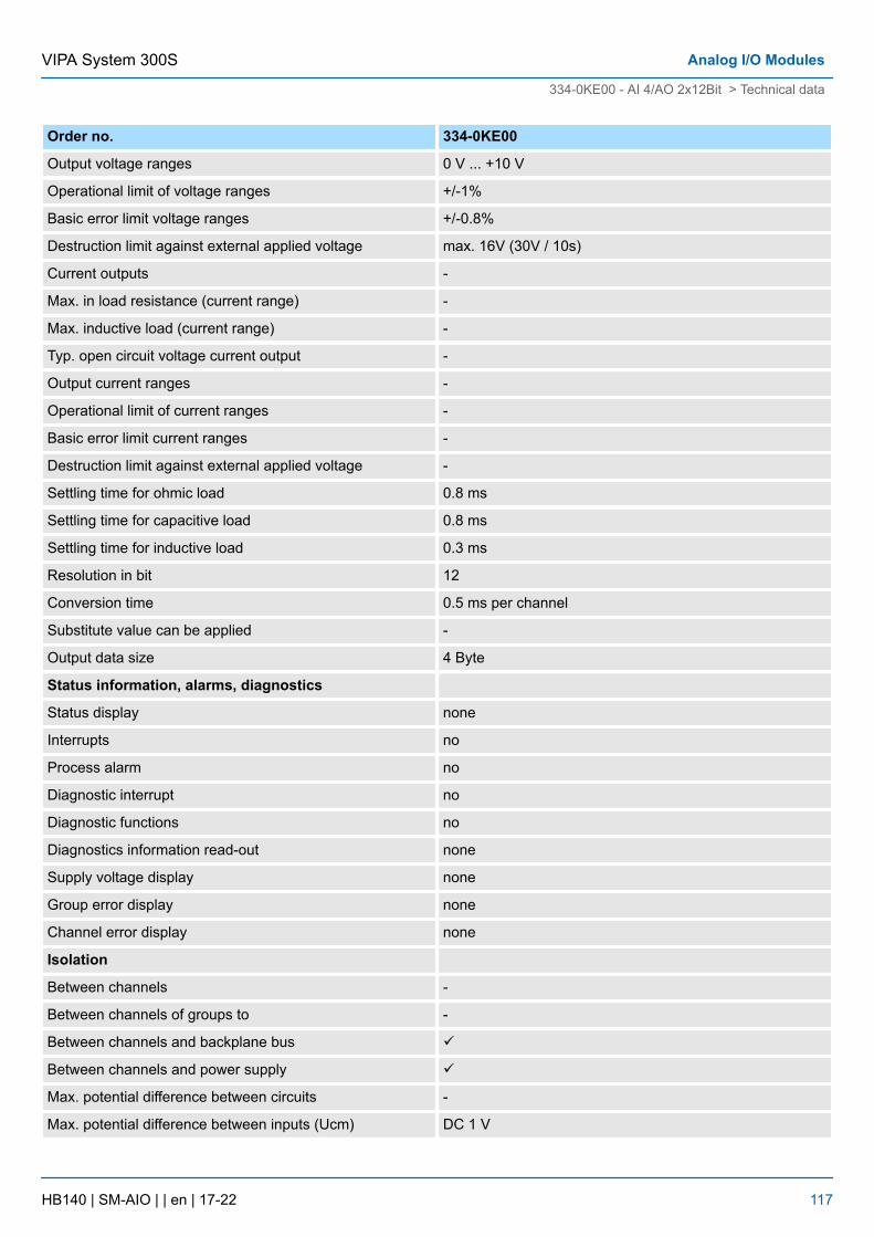
Order no. 334-0KE00
Output voltage ranges 0 V ... +10 V
Operational limit of voltage ranges +/-1%
Basic error limit voltage ranges +/-0.8%
Destruction limit against external applied voltage max. 16V (30V / 10s)
Current outputs -
Max. in load resistance (current range) -
Max. inductive load (current range) -
Typ. open circuit voltage current output -
Output current ranges -
Operational limit of current ranges -
Basic error limit current ranges -
Destruction limit against external applied voltage -
Settling time for ohmic load 0.8 ms
Settling time for capacitive load 0.8 ms
Settling time for inductive load 0.3 ms
Resolution in bit 12
Conversion time 0.5 ms per channel
Substitute value can be applied -
Output data size 4 Byte
Status information, alarms, diagnostics
Status display none
Interrupts no
Process alarm no
Diagnostic interrupt no
Diagnostic functions no
Diagnostics information read-out none
Supply voltage display none
Group error display none
Channel error display none
Isolation
Between channels -
Between channels of groups to -
Between channels and backplane bus ü
Between channels and power supply ü
Max. potential difference between circuits -
Max. potential difference between inputs (Ucm) DC 1 V
VIPA System 300S Analog I/O Modules
334-0KE00 - AI 4/AO 2x12Bit > Technical data
HB140 | SM-AIO | | en | 17-22 117
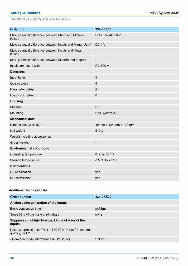
Order no. 334-0KE00
Max. potential difference between Mana and Mintern(Uiso)
DC 75 V/ AC 50 V
Max. potential difference between inputs and Mana (Ucm) DC 1 V
Max. potential difference between inputs and Mintern(Uiso)
-
Max. potential difference between Mintern and outputs -
Insulation tested with DC 500 V
Datasizes
Input bytes 8
Output bytes 4
Parameter bytes 21
Diagnostic bytes 0
Housing
Material PPE
Mounting Rail System 300
Mechanical data
Dimensions (WxHxD) 40 mm x 125 mm x 120 mm
Net weight 210 g
Weight including accessories -
Gross weight -
Environmental conditions
Operating temperature 0 °C to 60 °C
Storage temperature -25 °C to 70 °C
Certifications
UL certification yes
KC certification yes
Additional Technical data
Order number 334-0KE00
Analog value generation of the inputs
Basic conversion time nx72ms
Smoothing of the measured values none
Suppression of interference, Limits of error of theinputs
Noise suppression for f=n x (f1 ±1%) (f1= interference fre-quency, n=1,2,...)
- Common mode interference (UCM <13V) > 80dB
VIPA System 300SAnalog I/O Modules
334-0KE00 - AI 4/AO 2x12Bit > Technical data
HB140 | SM-AIO | | en | 17-22 118
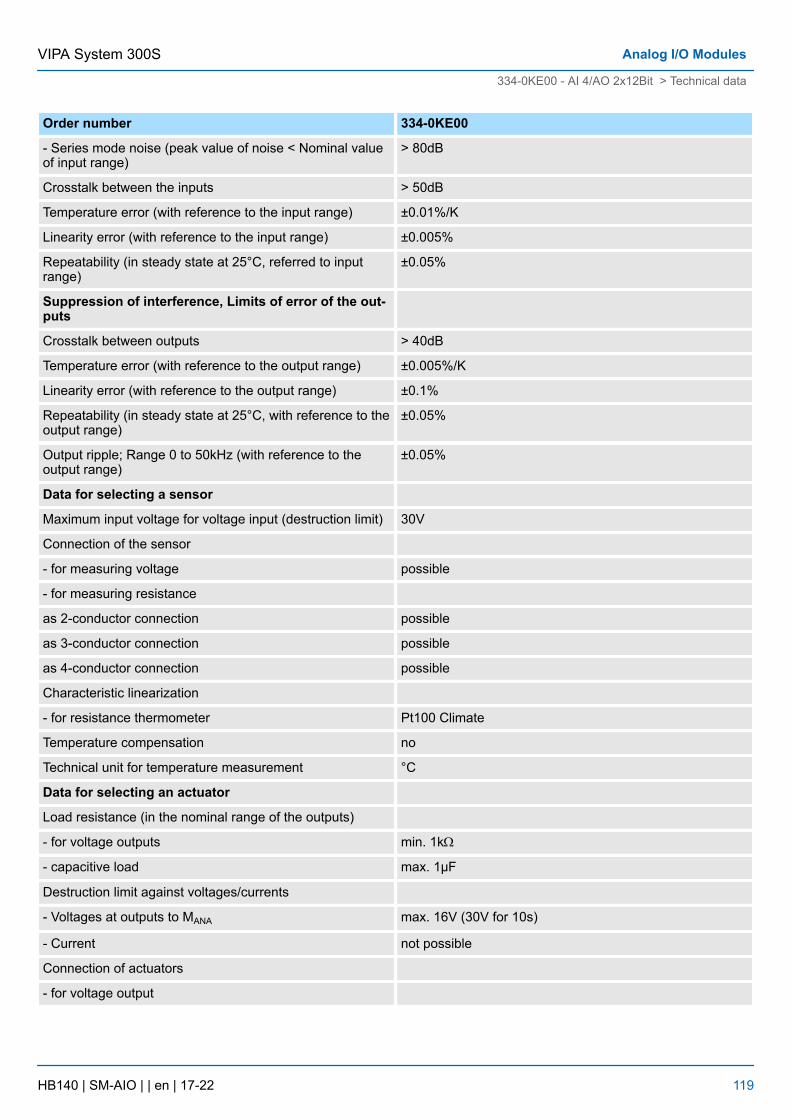
Order number 334-0KE00
- Series mode noise (peak value of noise < Nominal valueof input range)
> 80dB
Crosstalk between the inputs > 50dB
Temperature error (with reference to the input range) ±0.01%/K
Linearity error (with reference to the input range) ±0.005%
Repeatability (in steady state at 25°C, referred to inputrange)
±0.05%
Suppression of interference, Limits of error of the out-puts
Crosstalk between outputs > 40dB
Temperature error (with reference to the output range) ±0.005%/K
Linearity error (with reference to the output range) ±0.1%
Repeatability (in steady state at 25°C, with reference to theoutput range)
±0.05%
Output ripple; Range 0 to 50kHz (with reference to theoutput range)
±0.05%
Data for selecting a sensor
Maximum input voltage for voltage input (destruction limit) 30V
Connection of the sensor
- for measuring voltage possible
- for measuring resistance
as 2-conductor connection possible
as 3-conductor connection possible
as 4-conductor connection possible
Characteristic linearization
- for resistance thermometer Pt100 Climate
Temperature compensation no
Technical unit for temperature measurement °C
Data for selecting an actuator
Load resistance (in the nominal range of the outputs)
- for voltage outputs min. 1kW
- capacitive load max. 1µF
Destruction limit against voltages/currents
- Voltages at outputs to MANA max. 16V (30V for 10s)
- Current not possible
Connection of actuators
- for voltage output
VIPA System 300S Analog I/O Modules
334-0KE00 - AI 4/AO 2x12Bit > Technical data
HB140 | SM-AIO | | en | 17-22 119
Order number 334-0KE00
2-conductor connection possible
4-conductor connection not possible
VIPA System 300SAnalog I/O Modules
334-0KE00 - AI 4/AO 2x12Bit > Technical data
HB140 | SM-AIO | | en | 17-22 120
6 Analog I/O Modules FAST - SPEED-Bus6.1 General
For analog signals you should use isolated cables to reduce interference. The cablescreening should be grounded at both ends. If there are differences in the potentialbetween the cable ends, there may occur a potential compensating current that could dis-turb the analog signals. In this case you should ground the cable screening only at oneend.
Depending on the module the following sensors may be connected to the analog inputmodules:
n Current sensor ±20mAn Voltage sensor ±10V
Please take care of the correct polarity when installing the sensors!Please install short circuits at non-used inputs by connecting the positivecontact with the channel ground of the according channel.
The modules may be parameterized by hardware configuration respectively at run timeby means of SFCs.
The modules have diagnostics capability. The following errors can release a diagnostic:
n Error in parameterizationn Process interrupt lostn Measuring range over-/underflown External power supply is missing
The following events can be defined by parameterization to release a process interrupt:
n Limit overflown Limit underflown End of cycle as soon as measuring value conversion of every channel has finished.
At a process interrupt 4bytes of process interrupt data are transferred. The process inter-rupts are deactivated when using oscilloscope- or FIFO functions.
6.2 Analog value representationThe analog values are only processed by the CPU in binary representation. Hereby theprocess signals are transformed into digital format in the analog module and passed on tothe CPU as word variable. The digitized analog value is the same for input and outputvalues at the same nominal range. The analog value is represented as two's-complement
Analog value
High-Byte Low-Byte
Bit number 15 14 13 12 11 10 9 8 7 6 5 4 3 2 1 0
15Bit+SG SG Measuring value
Cables for analog signals
Connecting sensors
Parameterization
Diagnostic functions
Process interrupts
Numeric representation inSiemens S7 format
VIPA System 300S Analog I/O Modules FAST - SPEED-Bus
Analog value representation
HB140 | SM-AIO | | en | 17-22 121
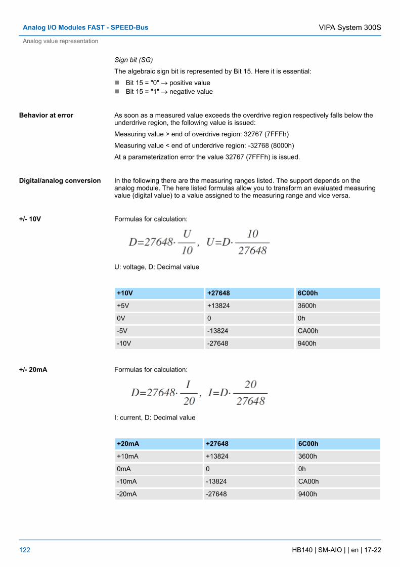
Sign bit (SG)
The algebraic sign bit is represented by Bit 15. Here it is essential:
n Bit 15 = "0" ® positive valuen Bit 15 = "1" ® negative value
As soon as a measured value exceeds the overdrive region respectively falls below theunderdrive region, the following value is issued:
Measuring value > end of overdrive region: 32767 (7FFFh)
Measuring value < end of underdrive region: -32768 (8000h)
At a parameterization error the value 32767 (7FFFh) is issued.
In the following there are the measuring ranges listed. The support depends on theanalog module. The here listed formulas allow you to transform an evaluated measuringvalue (digital value) to a value assigned to the measuring range and vice versa.
Formulas for calculation:
U: voltage, D: Decimal value
+10V +27648 6C00h
+5V +13824 3600h
0V 0 0h
-5V -13824 CA00h
-10V -27648 9400h
Formulas for calculation:
I: current, D: Decimal value
+20mA +27648 6C00h
+10mA +13824 3600h
0mA 0 0h
-10mA -13824 CA00h
-20mA -27648 9400h
Behavior at error
Digital/analog conversion
+/- 10V
+/- 20mA
VIPA System 300SAnalog I/O Modules FAST - SPEED-Bus
Analog value representation
HB140 | SM-AIO | | en | 17-22 122
6.3 Operating modesThere are the following modes at the analog input modules to be set by means of a hard-ware configuration at the Siemens SIMATIC Manager.
At the standard mode the analog values of the 8 input channels were cyclically read up to25µs, converted to 16bit digital values and transferred to the CPU via SPEED-Bus. Onlyfor cycle times ≥ 200µs an end of cycle interrupt may be activated. This is generated assoon as there are new measuring values available.
With the oscilloscope mode the digitized input values were buffered in the memory of themodule. There is space for a total of 65536 measuring values. At this mode hardwareinterrupts are not supported. Recording may be started manually or automatically,whereas there is reacted at a rising respectively falling edge of the measuring signal. Assoon as the memory of the module is full the recording ends automatically.
If FIFO mode is activated the input values of channel CH0 to CH7 are stored at a buffer.There is space for 8190 values each channel. These may cyclically be read in packets. Atoverflow the memory contents is overwritten from the beginning and an error is reported.
The activation of the oscilloscope-/FIFO function as well as the readout of the stored datahappens by means of the VIPA specific SFC 193.
There are a lot of parameters to adapt these functions to your requirements. The parame-ters may be set by GSD file respectively at run time by SFC 58.
6.4 Addressing at SPEED-BusTo provide specific addressing of the installed peripheral modules, certain addressesmust be allocated in the CPU. With no hardware configuration present, the CPU assignsautomatically peripheral I/O addresses during boot procedure depending on the plug-inlocation amongst others also for plugged modules at the SPEED-Bus.
In the hardware configurator from Siemens up to 8 modules per row may be parameter-ized. At deployment of SPEED7 CPUs up to 32 modules at the standard bus and 10 fur-ther modules at the SPEED-Bus may be controlled. CPs and DP masters that are addi-tionally virtual configured at the standard bus are taken into the sum of 32 modules at thestandard bus. For the project engineering of more than 8 modules you may use virtualline interface connections. For this you set in the hardware configurator the module IM360 from the hardware catalog to slot 3 of your 1. profile rail. Now you may extend yoursystem with up to 3 profile rails by starting each with an IM 361 from Siemens at slot 3.
You may access the modules with read res. write accesses to the peripheral bytes or theprocess image. To define addresses, a hardware configuration via a virtual PROFIBUSsystem by including the SPEEDBUS.GSD may be used. For this, click on the propertiesof the according module and set the wanted address.
If you do not like to use a hardware configuration, an automatic addressing comes intoforce. At the automatic address allocation DIOs are mapped depending on the slot loca-tion with a distance of 4byte and AIOs, FMs, CPs with a distance of 256byte. Dependingon the slot location the start address from where on the according module is stored in theaddress range is calculated with the following formulas:
Mode
Standard mode
Oscilloscope mode
FIFO mode
SFC 193
Parameter
Overview
Maximal pluggablemodules
Define addresses by hard-ware configuration
Automatic addressing
VIPA System 300S Analog I/O Modules FAST - SPEED-Bus
Addressing at SPEED-Bus
HB140 | SM-AIO | | en | 17-22 123
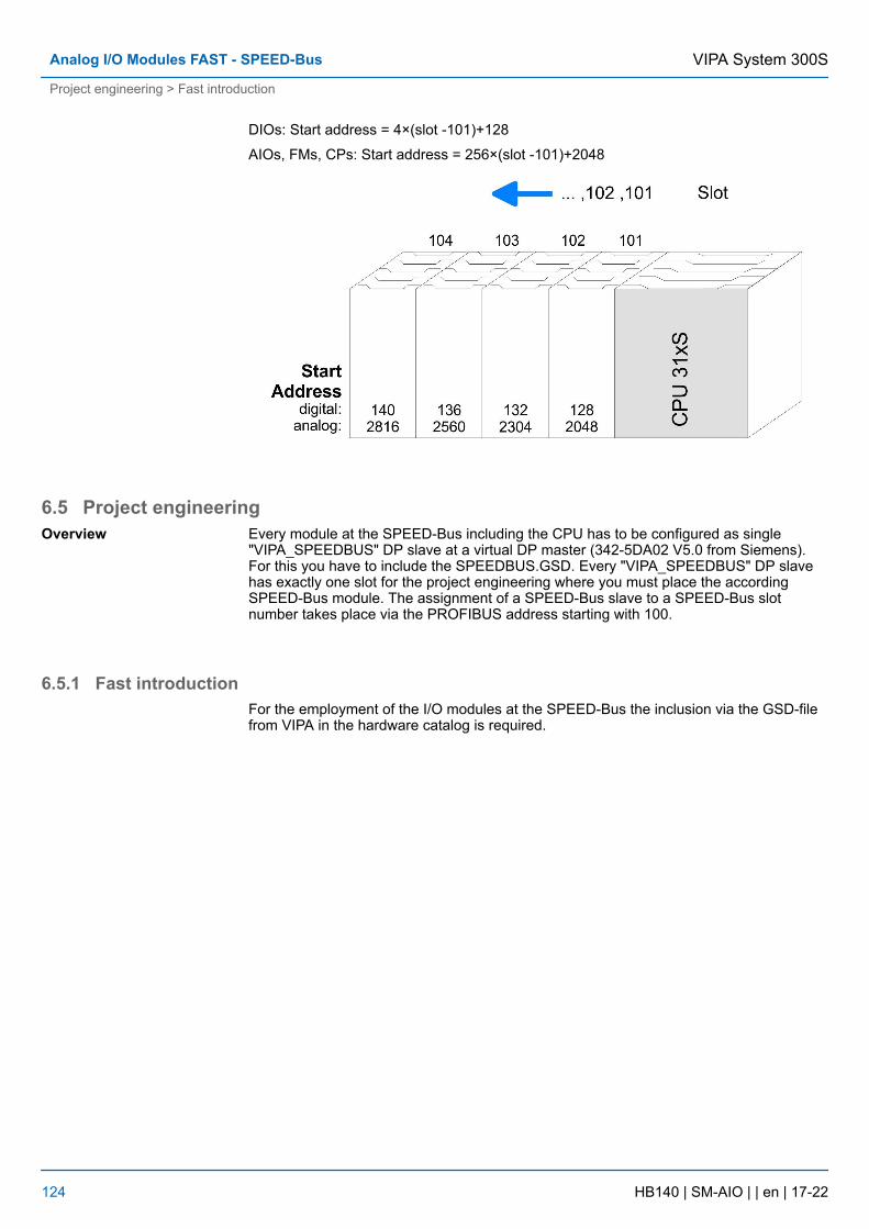
DIOs: Start address = 4×(slot -101)+128
AIOs, FMs, CPs: Start address = 256×(slot -101)+2048
6.5 Project engineeringEvery module at the SPEED-Bus including the CPU has to be configured as single"VIPA_SPEEDBUS" DP slave at a virtual DP master (342-5DA02 V5.0 from Siemens).For this you have to include the SPEEDBUS.GSD. Every "VIPA_SPEEDBUS" DP slavehas exactly one slot for the project engineering where you must place the accordingSPEED-Bus module. The assignment of a SPEED-Bus slave to a SPEED-Bus slotnumber takes place via the PROFIBUS address starting with 100.
6.5.1 Fast introductionFor the employment of the I/O modules at the SPEED-Bus the inclusion via the GSD-filefrom VIPA in the hardware catalog is required.
Overview
VIPA System 300SAnalog I/O Modules FAST - SPEED-Bus
Project engineering > Fast introduction
HB140 | SM-AIO | | en | 17-22 124
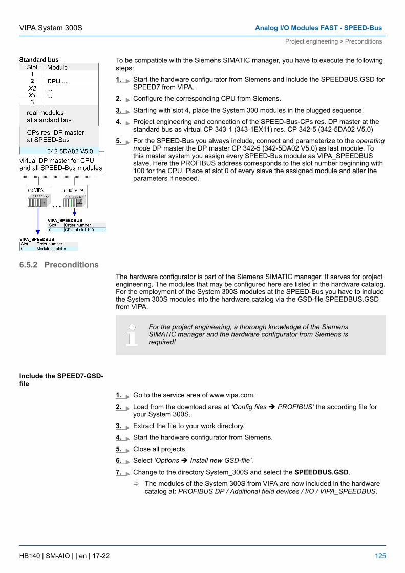
To be compatible with the Siemens SIMATIC manager, you have to execute the followingsteps:
1. Start the hardware configurator from Siemens and include the SPEEDBUS.GSD forSPEED7 from VIPA.
2. Configure the corresponding CPU from Siemens.
3. Starting with slot 4, place the System 300 modules in the plugged sequence.
4. Project engineering and connection of the SPEED-Bus-CPs res. DP master at thestandard bus as virtual CP 343-1 (343-1EX11) res. CP 342-5 (342-5DA02 V5.0)
5. For the SPEED-Bus you always include, connect and parameterize to the operatingmode DP master the DP master CP 342-5 (342-5DA02 V5.0) as last module. Tothis master system you assign every SPEED-Bus module as VIPA_SPEEDBUSslave. Here the PROFIBUS address corresponds to the slot number beginning with100 for the CPU. Place at slot 0 of every slave the assigned module and alter theparameters if needed.
6.5.2 PreconditionsThe hardware configurator is part of the Siemens SIMATIC manager. It serves for projectengineering. The modules that may be configured here are listed in the hardware catalog.For the employment of the System 300S modules at the SPEED-Bus you have to includethe System 300S modules into the hardware catalog via the GSD-file SPEEDBUS.GSDfrom VIPA.
For the project engineering, a thorough knowledge of the SiemensSIMATIC manager and the hardware configurator from Siemens isrequired!
1. Go to the service area of www.vipa.com.
2. Load from the download area at ‘Config files è PROFIBUS’ the according file foryour System 300S.
3. Extract the file to your work directory.
4. Start the hardware configurator from Siemens.
5. Close all projects.
6. Select ‘Options è Install new GSD-file’.
7. Change to the directory System_300S and select the SPEEDBUS.GSD.
ð The modules of the System 300S from VIPA are now included in the hardwarecatalog at: PROFIBUS DP / Additional field devices / I/O / VIPA_SPEEDBUS.
Include the SPEED7-GSD-file
VIPA System 300S Analog I/O Modules FAST - SPEED-Bus
Project engineering > Preconditions
HB140 | SM-AIO | | en | 17-22 125
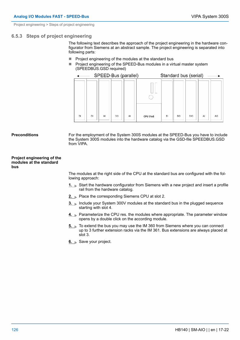
6.5.3 Steps of project engineeringThe following text describes the approach of the project engineering in the hardware con-figurator from Siemens at an abstract sample. The project engineering is separated intofollowing parts:
n Project engineering of the modules at the standard busn Project engineering of the SPEED-Bus modules in a virtual master system
(SPEEDBUS.GSD required)
For the employment of the System 300S modules at the SPEED-Bus you have to includethe System 300S modules into the hardware catalog via the GSD-file SPEEDBUS.GSDfrom VIPA.
The modules at the right side of the CPU at the standard bus are configured with the fol-lowing approach:
1. Start the hardware configurator from Siemens with a new project and insert a profilerail from the hardware catalog.
2. Place the corresponding Siemens CPU at slot 2.
3. Include your System 300V modules at the standard bus in the plugged sequencestarting with slot 4.
4. Parameterize the CPU res. the modules where appropriate. The parameter windowopens by a double click on the according module.
5. To extend the bus you may use the IM 360 from Siemens where you can connectup to 3 further extension racks via the IM 361. Bus extensions are always placed atslot 3.
6. Save your project.
Preconditions
Project engineering of themodules at the standardbus
VIPA System 300SAnalog I/O Modules FAST - SPEED-Bus
Project engineering > Steps of project engineering
HB140 | SM-AIO | | en | 17-22 126
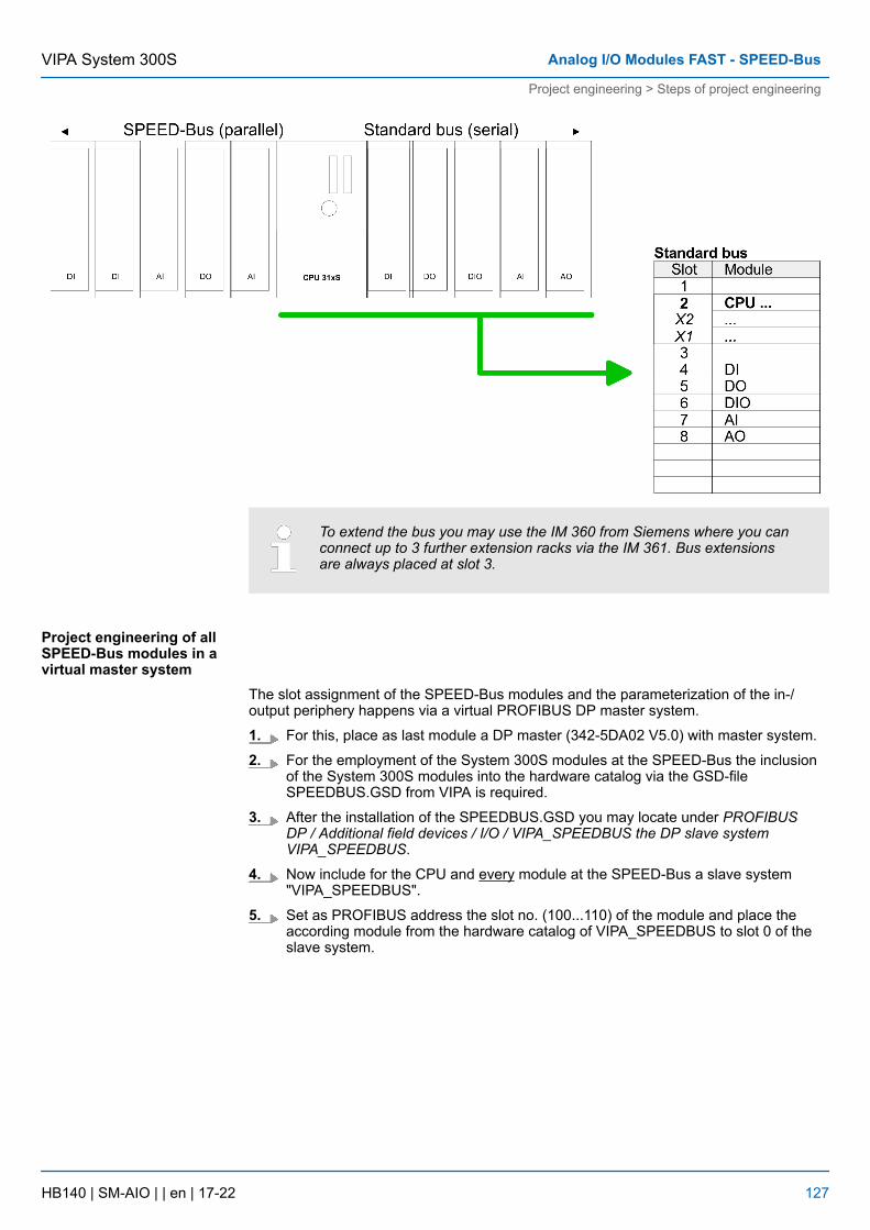
To extend the bus you may use the IM 360 from Siemens where you canconnect up to 3 further extension racks via the IM 361. Bus extensionsare always placed at slot 3.
The slot assignment of the SPEED-Bus modules and the parameterization of the in-/output periphery happens via a virtual PROFIBUS DP master system.
1. For this, place as last module a DP master (342-5DA02 V5.0) with master system.
2. For the employment of the System 300S modules at the SPEED-Bus the inclusionof the System 300S modules into the hardware catalog via the GSD-fileSPEEDBUS.GSD from VIPA is required.
3. After the installation of the SPEEDBUS.GSD you may locate under PROFIBUSDP / Additional field devices / I/O / VIPA_SPEEDBUS the DP slave systemVIPA_SPEEDBUS.
4. Now include for the CPU and every module at the SPEED-Bus a slave system"VIPA_SPEEDBUS".
5. Set as PROFIBUS address the slot no. (100...110) of the module and place theaccording module from the hardware catalog of VIPA_SPEEDBUS to slot 0 of theslave system.
Project engineering of allSPEED-Bus modules in avirtual master system
VIPA System 300S Analog I/O Modules FAST - SPEED-Bus
Project engineering > Steps of project engineering
HB140 | SM-AIO | | en | 17-22 127
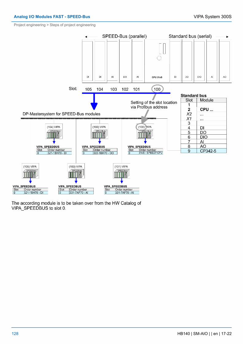
VIPA System 300SAnalog I/O Modules FAST - SPEED-Bus
Project engineering > Steps of project engineering
HB140 | SM-AIO | | en | 17-22 128
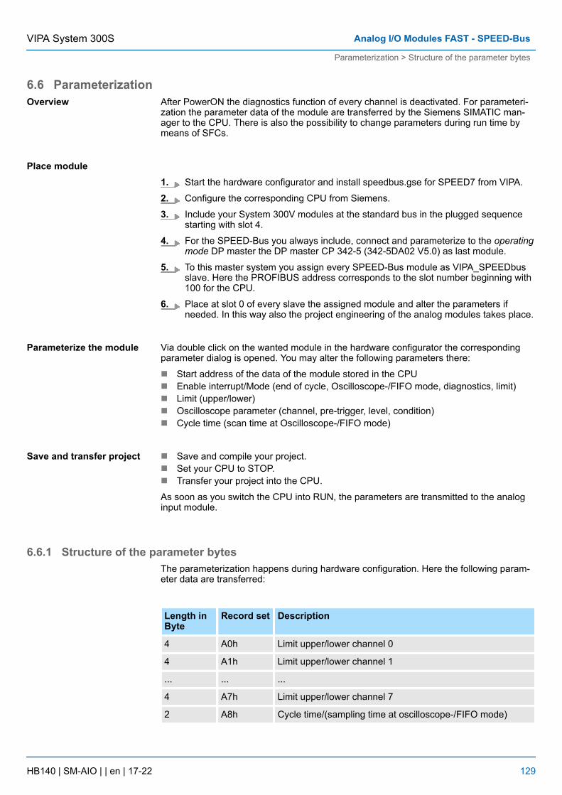
6.6 ParameterizationAfter PowerON the diagnostics function of every channel is deactivated. For parameteri-zation the parameter data of the module are transferred by the Siemens SIMATIC man-ager to the CPU. There is also the possibility to change parameters during run time bymeans of SFCs.
1. Start the hardware configurator and install speedbus.gse for SPEED7 from VIPA.
2. Configure the corresponding CPU from Siemens.
3. Include your System 300V modules at the standard bus in the plugged sequencestarting with slot 4.
4. For the SPEED-Bus you always include, connect and parameterize to the operatingmode DP master the DP master CP 342-5 (342-5DA02 V5.0) as last module.
5. To this master system you assign every SPEED-Bus module as VIPA_SPEEDbusslave. Here the PROFIBUS address corresponds to the slot number beginning with100 for the CPU.
6. Place at slot 0 of every slave the assigned module and alter the parameters ifneeded. In this way also the project engineering of the analog modules takes place.
Via double click on the wanted module in the hardware configurator the correspondingparameter dialog is opened. You may alter the following parameters there:
n Start address of the data of the module stored in the CPUn Enable interrupt/Mode (end of cycle, Oscilloscope-/FIFO mode, diagnostics, limit)n Limit (upper/lower)n Oscilloscope parameter (channel, pre-trigger, level, condition)n Cycle time (scan time at Oscilloscope-/FIFO mode)
n Save and compile your project.n Set your CPU to STOP.n Transfer your project into the CPU.
As soon as you switch the CPU into RUN, the parameters are transmitted to the analoginput module.
6.6.1 Structure of the parameter bytesThe parameterization happens during hardware configuration. Here the following param-eter data are transferred:
Length inByte
Record set Description
4 A0h Limit upper/lower channel 0
4 A1h Limit upper/lower channel 1
... ... ...
4 A7h Limit upper/lower channel 7
2 A8h Cycle time/(sampling time at oscilloscope-/FIFO mode)
Overview
Place module
Parameterize the module
Save and transfer project
VIPA System 300S Analog I/O Modules FAST - SPEED-Bus
Parameterization > Structure of the parameter bytes
HB140 | SM-AIO | | en | 17-22 129
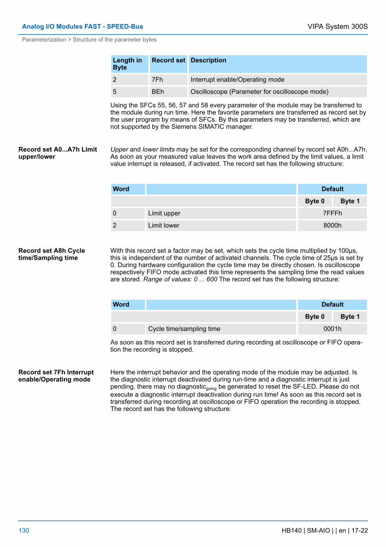
Length inByte
Record set Description
2 7Fh Interrupt enable/Operating mode
5 BEh Oscilloscope (Parameter for oscilloscope mode)
Using the SFCs 55, 56, 57 and 58 every parameter of the module may be transferred tothe module during run time. Here the favorite parameters are transferred as record set bythe user program by means of SFCs. By this parameters may be transferred, which arenot supported by the Siemens SIMATIC manager.
Upper and lower limits may be set for the corresponding channel by record set A0h...A7h.As soon as your measured value leaves the work area defined by the limit values, a limitvalue interrupt is released, if activated. The record set has the following structure:
Word Default
Byte 0 Byte 1
0 Limit upper 7FFFh
2 Limit lower 8000h
With this record set a factor may be set, which sets the cycle time multiplied by 100µs,this is independent of the number of activated channels. The cycle time of 25µs is set by0. During hardware configuration the cycle time may be directly chosen. Is oscilloscoperespectively FIFO mode activated this time represents the sampling time the read valuesare stored. Range of values: 0 ... 600 The record set has the following structure:
Word Default
Byte 0 Byte 1
0 Cycle time/sampling time 0001h
As soon as this record set is transferred during recording at oscilloscope or FIFO opera-tion the recording is stopped.
Here the interrupt behavior and the operating mode of the module may be adjusted. Isthe diagnostic interrupt deactivated during run-time and a diagnostic interrupt is justpending, there may no diagnosticgoing be generated to reset the SF-LED. Please do notexecute a diagnostic interrupt deactivation during run time! As soon as this record set istransferred during recording at oscilloscope or FIFO operation the recording is stopped.The record set has the following structure:
Record set A0...A7h Limitupper/lower
Record set A8h Cycletime/Sampling time
Record set 7Fh Interruptenable/Operating mode
VIPA System 300SAnalog I/O Modules FAST - SPEED-Bus
Parameterization > Structure of the parameter bytes
HB140 | SM-AIO | | en | 17-22 130
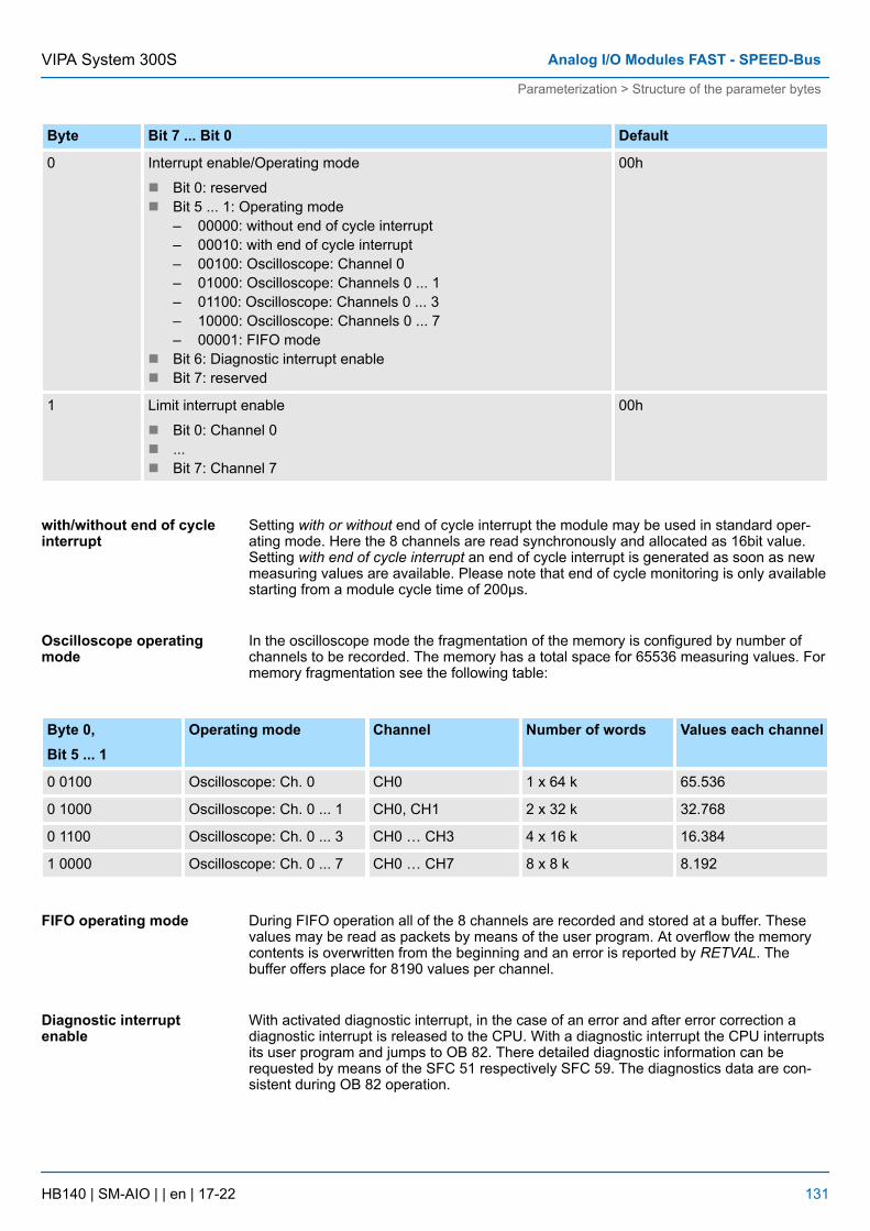
Byte Bit 7 ... Bit 0 Default
0 Interrupt enable/Operating mode
n Bit 0: reservedn Bit 5 ... 1: Operating mode
– 00000: without end of cycle interrupt– 00010: with end of cycle interrupt– 00100: Oscilloscope: Channel 0– 01000: Oscilloscope: Channels 0 ... 1– 01100: Oscilloscope: Channels 0 ... 3– 10000: Oscilloscope: Channels 0 ... 7– 00001: FIFO mode
n Bit 6: Diagnostic interrupt enablen Bit 7: reserved
00h
1 Limit interrupt enable
n Bit 0: Channel 0n ...n Bit 7: Channel 7
00h
Setting with or without end of cycle interrupt the module may be used in standard oper-ating mode. Here the 8 channels are read synchronously and allocated as 16bit value.Setting with end of cycle interrupt an end of cycle interrupt is generated as soon as newmeasuring values are available. Please note that end of cycle monitoring is only availablestarting from a module cycle time of 200µs.
In the oscilloscope mode the fragmentation of the memory is configured by number ofchannels to be recorded. The memory has a total space for 65536 measuring values. Formemory fragmentation see the following table:
Byte 0,Bit 5 ... 1
Operating mode Channel Number of words Values each channel
0 0100 Oscilloscope: Ch. 0 CH0 1 x 64 k 65.536
0 1000 Oscilloscope: Ch. 0 ... 1 CH0, CH1 2 x 32 k 32.768
0 1100 Oscilloscope: Ch. 0 ... 3 CH0 … CH3 4 x 16 k 16.384
1 0000 Oscilloscope: Ch. 0 ... 7 CH0 … CH7 8 x 8 k 8.192
During FIFO operation all of the 8 channels are recorded and stored at a buffer. Thesevalues may be read as packets by means of the user program. At overflow the memorycontents is overwritten from the beginning and an error is reported by RETVAL. Thebuffer offers place for 8190 values per channel.
With activated diagnostic interrupt, in the case of an error and after error correction adiagnostic interrupt is released to the CPU. With a diagnostic interrupt the CPU interruptsits user program and jumps to OB 82. There detailed diagnostic information can berequested by means of the SFC 51 respectively SFC 59. The diagnostics data are con-sistent during OB 82 operation.
with/without end of cycleinterrupt
Oscilloscope operatingmode
FIFO operating mode
Diagnostic interruptenable
VIPA System 300S Analog I/O Modules FAST - SPEED-Bus
Parameterization > Structure of the parameter bytes
HB140 | SM-AIO | | en | 17-22 131
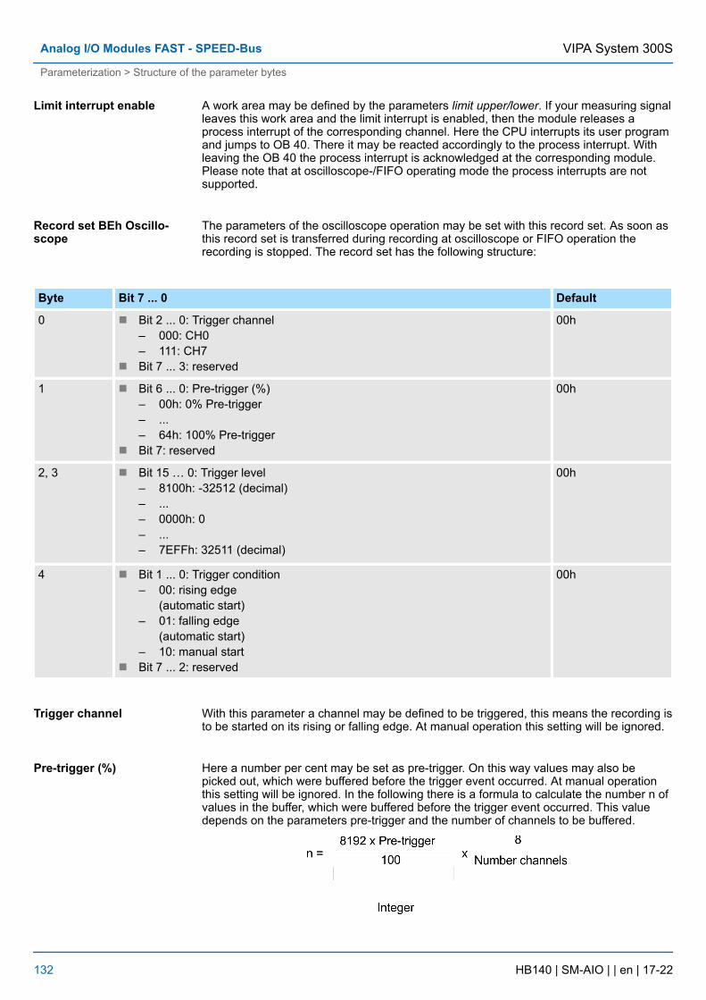
A work area may be defined by the parameters limit upper/lower. If your measuring signalleaves this work area and the limit interrupt is enabled, then the module releases aprocess interrupt of the corresponding channel. Here the CPU interrupts its user programand jumps to OB 40. There it may be reacted accordingly to the process interrupt. Withleaving the OB 40 the process interrupt is acknowledged at the corresponding module.Please note that at oscilloscope-/FIFO operating mode the process interrupts are notsupported.
The parameters of the oscilloscope operation may be set with this record set. As soon asthis record set is transferred during recording at oscilloscope or FIFO operation therecording is stopped. The record set has the following structure:
Byte Bit 7 ... 0 Default
0 n Bit 2 ... 0: Trigger channel– 000: CH0– 111: CH7
n Bit 7 ... 3: reserved
00h
1 n Bit 6 ... 0: Pre-trigger (%)– 00h: 0% Pre-trigger– ...– 64h: 100% Pre-trigger
n Bit 7: reserved
00h
2, 3 n Bit 15 … 0: Trigger level– 8100h: -32512 (decimal)– ...– 0000h: 0– ...– 7EFFh: 32511 (decimal)
00h
4 n Bit 1 ... 0: Trigger condition– 00: rising edge
(automatic start)– 01: falling edge
(automatic start)– 10: manual start
n Bit 7 ... 2: reserved
00h
With this parameter a channel may be defined to be triggered, this means the recording isto be started on its rising or falling edge. At manual operation this setting will be ignored.
Here a number per cent may be set as pre-trigger. On this way values may also bepicked out, which were buffered before the trigger event occurred. At manual operationthis setting will be ignored. In the following there is a formula to calculate the number n ofvalues in the buffer, which were buffered before the trigger event occurred. This valuedepends on the parameters pre-trigger and the number of channels to be buffered.
Limit interrupt enable
Record set BEh Oscillo-scope
Trigger channel
Pre-trigger (%)
VIPA System 300SAnalog I/O Modules FAST - SPEED-Bus
Parameterization > Structure of the parameter bytes
HB140 | SM-AIO | | en | 17-22 132
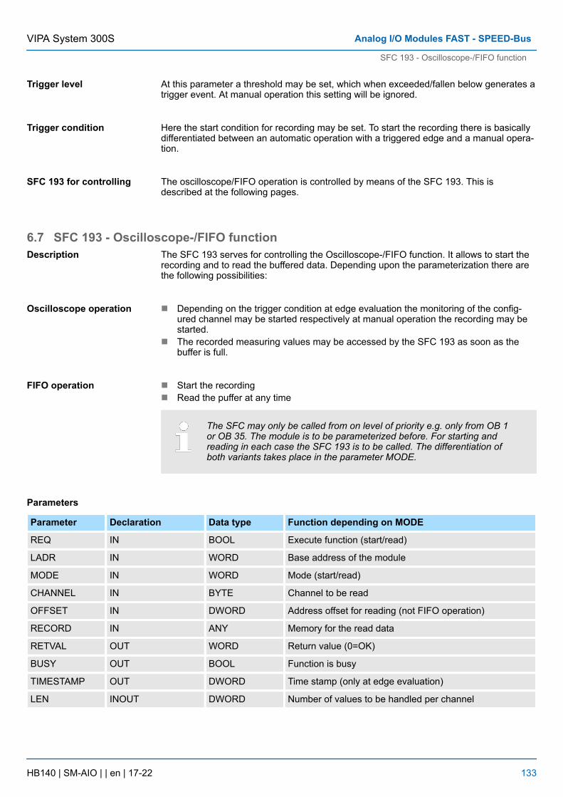
At this parameter a threshold may be set, which when exceeded/fallen below generates atrigger event. At manual operation this setting will be ignored.
Here the start condition for recording may be set. To start the recording there is basicallydifferentiated between an automatic operation with a triggered edge and a manual opera-tion.
The oscilloscope/FIFO operation is controlled by means of the SFC 193. This isdescribed at the following pages.
6.7 SFC 193 - Oscilloscope-/FIFO functionThe SFC 193 serves for controlling the Oscilloscope-/FIFO function. It allows to start therecording and to read the buffered data. Depending upon the parameterization there arethe following possibilities:
n Depending on the trigger condition at edge evaluation the monitoring of the config-ured channel may be started respectively at manual operation the recording may bestarted.
n The recorded measuring values may be accessed by the SFC 193 as soon as thebuffer is full.
n Start the recordingn Read the puffer at any time
The SFC may only be called from on level of priority e.g. only from OB 1or OB 35. The module is to be parameterized before. For starting andreading in each case the SFC 193 is to be called. The differentiation ofboth variants takes place in the parameter MODE.
Parameters
Parameter Declaration Data type Function depending on MODE
REQ IN BOOL Execute function (start/read)
LADR IN WORD Base address of the module
MODE IN WORD Mode (start/read)
CHANNEL IN BYTE Channel to be read
OFFSET IN DWORD Address offset for reading (not FIFO operation)
RECORD IN ANY Memory for the read data
RETVAL OUT WORD Return value (0=OK)
BUSY OUT BOOL Function is busy
TIMESTAMP OUT DWORD Time stamp (only at edge evaluation)
LEN INOUT DWORD Number of values to be handled per channel
Trigger level
Trigger condition
SFC 193 for controlling
Description
Oscilloscope operation
FIFO operation
VIPA System 300S Analog I/O Modules FAST - SPEED-Bus
SFC 193 - Oscilloscope-/FIFO function
HB140 | SM-AIO | | en | 17-22 133
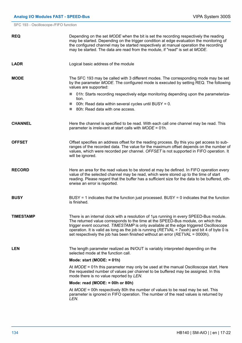
Depending on the set MODE when the bit is set the recording respectively the readingmay be started. Depending on the trigger condition at edge evaluation the monitoring ofthe configured channel may be started respectively at manual operation the recordingmay be started. The data are read from the module, if "read" is set at MODE.
Logical basic address of the module
The SFC 193 may be called with 3 different modes. The corresponding mode may be setby the parameter MODE. The configured mode is executed by setting REQ. The followingvalues are supported:
n 01h: Starts recording respectively edge monitoring depending upon the parameteriza-tion.
n 00h: Read data within several cycles until BUSY = 0.n 80h: Read data with one access.
Here the channel is specified to be read. With each call one channel may be read. Thisparameter is irrelevant at start calls with MODE = 01h.
Offset specifies an address offset for the reading process. By this you get access to sub-ranges of the recorded data. The value for the maximum offset depends on the number ofvalues, which were recorded per channel. OFFSET is not supported in FIFO operation. Itwill be ignored.
Here an area for the read values to be stored at may be defined. In FIFO operation everyvalue of the selected channel may be read, which were stored up to the time of startreading. Please regard that the buffer has a sufficient size for the data to be buffered, oth-erwise an error is reported.
BUSY = 1 indicates that the function just processed. BUSY = 0 indicates that the functionis finished.
There is an internal clock with a resolution of 1µs running in every SPEED-Bus module.The returned value corresponds to the time at the SPEED-Bus module, on which thetrigger event occurred. TIMESTAMP is only available at the edge triggered Oscilloscopeoperation. It is valid as long as the job is running (RETVAL = 7xxxh) and bit 4 of byte 0 isset respectively the job has been finished without an error (RETVAL = 0000h).
The length parameter realized as IN/OUT is variably interpreted depending on theselected mode at the function call.
Mode: start (MODE: = 01h)At MODE = 01h this parameter may only be used at the manual Oscilloscope start. Herethe requested number of values per channel to be buffered may be assigned. In thismode there is no value reported by LEN.
Mode: read (MODE: = 00h or 80h)At MODE = 00h respectively 80h the number of values to be read may be set. Thisparameter is ignored in FIFO operation. The number of the read values is returned byLEN.
REQ
LADR
MODE
CHANNEL
OFFSET
RECORD
BUSY
TIMESTAMP
LEN
VIPA System 300SAnalog I/O Modules FAST - SPEED-Bus
SFC 193 - Oscilloscope-/FIFO function
HB140 | SM-AIO | | en | 17-22 134
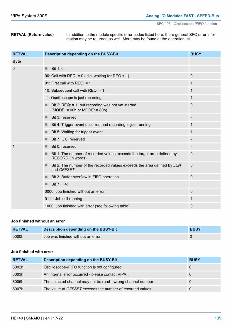
In addition to the module specific error codes listed here, there general SFC error infor-mation may be returned as well. More may be found at the operation list.
RETVAL Description depending on the BUSY-Bit BUSY
Byte
0 n Bit 1, 0:
00: Call with REQ: = 0 (idle, waiting for REQ = 1) 0
01: First call with REQ: = 1 1
10: Subsequent call with REQ: = 1 1
11: Oscilloscope is just recording. 1
n Bit 2: REQ: = 1, but recording was not yet started.(MODE: = 00h or MODE: = 80h)
0
n Bit 3: reserved -
n Bit 4: Trigger event occurred and recording is just running. 1
n Bit 5: Waiting for trigger event 1
n Bit 7 … 6: reserved -
1 n Bit 0: reserved -
n Bit 1: The number of recorded values exceeds the target area defined byRECORD (in words).
0
n Bit 2: The number of the recorded values exceeds the area defined by LENand OFFSET.
0
n Bit 3: Buffer overflow in FIFO operation. 0
n Bit 7 ... 4:
0000: Job finished without an error 0
0111: Job still running 1
1000: Job finished with error (see following table) 0
Job finished without an error
RETVAL Description depending on the BUSY-Bit BUSY
0000h Job was finished without an error. 0
Job finished with error
RETVAL Description depending on the BUSY-Bit BUSY
8002h: Oscilloscope-/FIFO function is not configured. 0
8003h: An internal error occurred - please contact VIPA. 0
8005h: The selected channel may not be read - wrong channel number. 0
8007h: The value at OFFSET exceeds the number of recorded values. 0
RETVAL (Return value)
VIPA System 300S Analog I/O Modules FAST - SPEED-Bus
SFC 193 - Oscilloscope-/FIFO function
HB140 | SM-AIO | | en | 17-22 135
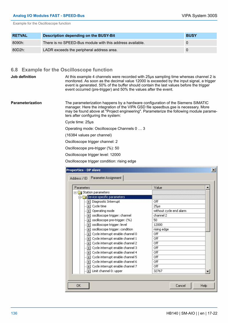
RETVAL Description depending on the BUSY-Bit BUSY
8090h: There is no SPEED-Bus module with this address available. 0
80D2h: LADR exceeds the peripheral address area. 0
6.8 Example for the Oscilloscope functionAt this example 4 channels were recorded with 25µs sampling time whereas channel 2 ismonitored. As soon as the decimal value 12000 is exceeded by the input signal, a triggerevent is generated. 50% of the buffer should contain the last values before the triggerevent occurred (pre-trigger) and 50% the values after the event.
The parameterization happens by a hardware configuration of the Siemens SIMATICmanager. Here the integration of the VIPA GSD file speedbus.gse is necessary. Moremay be found above at "Project engineering". Parameterize the following module parame-ters after configuring the system:
Cycle time: 25µs
Operating mode: Oscilloscope Channels 0 … 3
(16384 values per channel)
Oscilloscope trigger channel: 2
Oscilloscope pre-trigger (%): 50
Oscilloscope trigger level: 12000
Oscilloscope trigger condition: rising edge
Job definition
Parameterization
VIPA System 300SAnalog I/O Modules FAST - SPEED-Bus
Example for the Oscilloscope function
HB140 | SM-AIO | | en | 17-22 136
The SFC 193 calls for starting the oscilloscope recording and for reading the data areimplemented in the OB 1 of the user program. For the simplified representation and forcontrolling the parameters are handled in a variable table.
CALL SFC 193 // start oscilloscope function (1. SFC call)
REQ :=M99.0 // bit to start recording
LADR :=W#16#64 // basic module address
MODE :=W#16#1 // mode: start
CHANNEL :=B#16#0 // not used
OFFSET :=DW#16#0 // not used
RECORD :=DB10 // not used
RETVAL :=MW1110 // return value
BUSY :=M112.0 // busy bit
TIMESTAMP:=MD100 // not used
LEN :=MD114 // length parameter for recording
// (only at "manual start")
U M 99.0 // request bit set by 1. call?
S M 98.1 // yes: set request bit for 2. call
R M 99.0 // Reset request bit for 1. call
CALL SFC 193 // read data (2. SFC call)
REQ :=M98.1 // bit for reading the data
LADR :=W#16#64 // basic module address
MODE :=W#16#80 // mode: read (complete, 1 access)
CHANNEL :=MB148 // channel to be read
OFFSET :=MD150 // address offset for reading
RECORD :=DB10 // data block for the read values
RETVAL :=MW110 // return value
BUSY :=M112.0 // busy bit
TIMESTAMP:=MD104 // timestamp at trigger event
LEN :=MD114 // length parameter for reading
U M 98.1 // request bit set and
U M 112.0 // busy bit set?
BEB // yes: reading is not yet finished; finish block
U M 98.1 // request bit is set and
UN M 112.0 // busy bit is not set?
SPBN end // no: jump to label end
L MW 110 // yes: load return value and
T MW 160 // transfer to flag
end: NOP 0U M 98.1R M 98.1 // reset request bit from 2. call
User program
VIPA System 300S Analog I/O Modules FAST - SPEED-Bus
Example for the Oscilloscope function
HB140 | SM-AIO | | en | 17-22 137
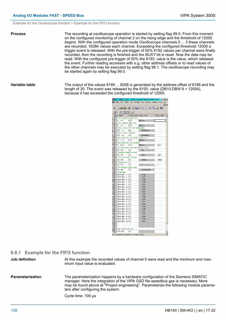
The recording at oscilloscope operation is started by setting flag 99.0. From this momenton the configured monitoring of channel 2 on the rising edge and the threshold of 12000begins. With the configured operation mode Oscilloscope channels 0 ... 3 these channelsare recorded, 16384 values each channel. Exceeding the configured threshold 12000 atrigger event is released. With the pre-trigger of 50% 8192 values per channel were finallyrecorded, then the recording is finished and the BUSY bit is reset. Now the data may beread. With the configured pre-trigger of 50% the 8193. value is the value, which releasedthe event. Further reading accesses with e.g. other address offsets or to read values ofthe other channels may be executed by setting flag 98.1. The oscilloscope recording maybe started again by setting flag 99.0.
The output of the values 8189 ... 8208 is generated by the address offset of 8188 and thelength of 20. The event was released by the 8193. value (DB10.DBW 8 = 12004),because it has exceeded the configured threshold of 12000.
6.8.1 Example for the FIFO functionAt this example the recorded values of channel 0 were read and the minimum and max-imum input value is evaluated.
The parameterization happens by a hardware configuration of the Siemens SIMATICmanager. Here the integration of the VIPA GSD file speedbus.gse is necessary. Moremay be found above at "Project engineering". Parameterize the following module parame-ters after configuring the system:
Cycle time: 100 µs
Process
Variable table
Job definition
Parameterization
VIPA System 300SAnalog I/O Modules FAST - SPEED-Bus
Example for the Oscilloscope function > Example for the FIFO function
HB140 | SM-AIO | | en | 17-22 138
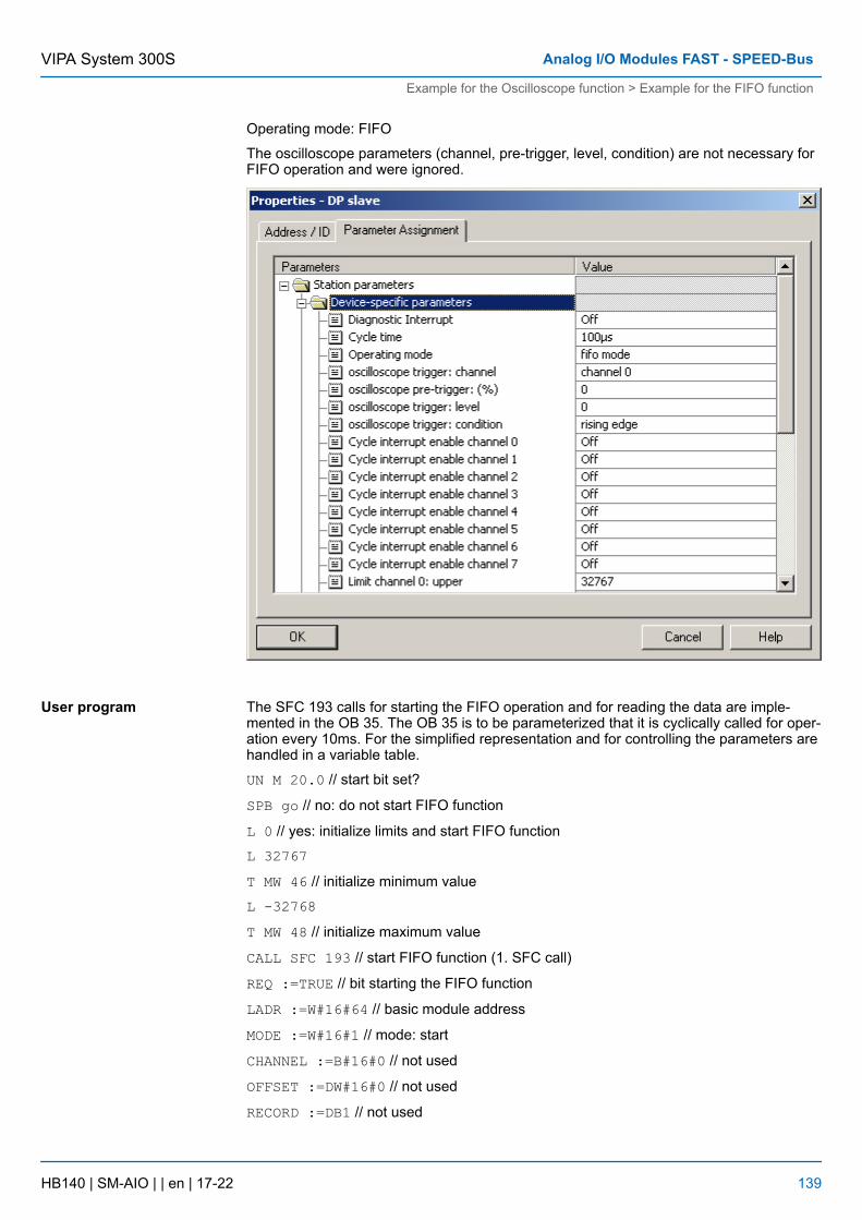
Operating mode: FIFO
The oscilloscope parameters (channel, pre-trigger, level, condition) are not necessary forFIFO operation and were ignored.
The SFC 193 calls for starting the FIFO operation and for reading the data are imple-mented in the OB 35. The OB 35 is to be parameterized that it is cyclically called for oper-ation every 10ms. For the simplified representation and for controlling the parameters arehandled in a variable table.
UN M 20.0 // start bit set?
SPB go // no: do not start FIFO function
L 0 // yes: initialize limits and start FIFO function
L 32767T MW 46 // initialize minimum value
L -32768T MW 48 // initialize maximum value
CALL SFC 193 // start FIFO function (1. SFC call)
REQ :=TRUE // bit starting the FIFO function
LADR :=W#16#64 // basic module address
MODE :=W#16#1 // mode: start
CHANNEL :=B#16#0 // not used
OFFSET :=DW#16#0 // not used
RECORD :=DB1 // not used
User program
VIPA System 300S Analog I/O Modules FAST - SPEED-Bus
Example for the Oscilloscope function > Example for the FIFO function
HB140 | SM-AIO | | en | 17-22 139

RETVAL :=MW22 // return value
BUSY :=M20.1 // busy bit
TIMESTAMP:=MD24 // not used
LEN :=MD28 // not used
U M 20.0 // reset start bit
R M 20.0S M 20.2 // start reading if FIFO active
go: UN M 20.2 // bit set for reading?
BEB // no: finish block
CALL SFC 193 // read data (2. SFC call)
REQ :=TRUE // bit for reading the data
LADR :=W#16#64 // basic module address
MODE :=W#16#80 // mode: read (complete, 1 access)
CHANNEL :=MB21 // channel to be read
OFFSET :=DW#16#0 // not used
RECORD :=DB1 // data block for the read values
RETVAL :=MW32 // return value
BUSY :=M20.3 // busy bit
TIMESTAMP:=MD34 // not used
LEN :=MD38 // length parameter for reading
L MD 38 // load length parameter
L 0==D // check if values were read
BEB // no: finish block
// every value in the buffer was read
// and stored in DB 1
L P#0.0 // set pointer to the 1. value of DB 1
T MD 42 // store pointer in flag
AUF DB 1 // open DB 1
// Check for new minimum:
loop: L DBW [MD 42 // load input value from DB
L MW 46 // load previous minimum value
>=I // is the input value exceeding // the previous minimum?
SPB max // yes: check for maximum
TAK // no: exchange accu1 and accu2 - then the measuring value is in // accu1 again
T MW 46 // store new minimum in flag //Check for a new maximum:
max: L DBW [MD 42] // load input value from DB
L MW 48 // load previous maximum
<=I // is the input value less the
// previous maximum?
VIPA System 300SAnalog I/O Modules FAST - SPEED-Bus
Example for the Oscilloscope function > Example for the FIFO function
HB140 | SM-AIO | | en | 17-22 140
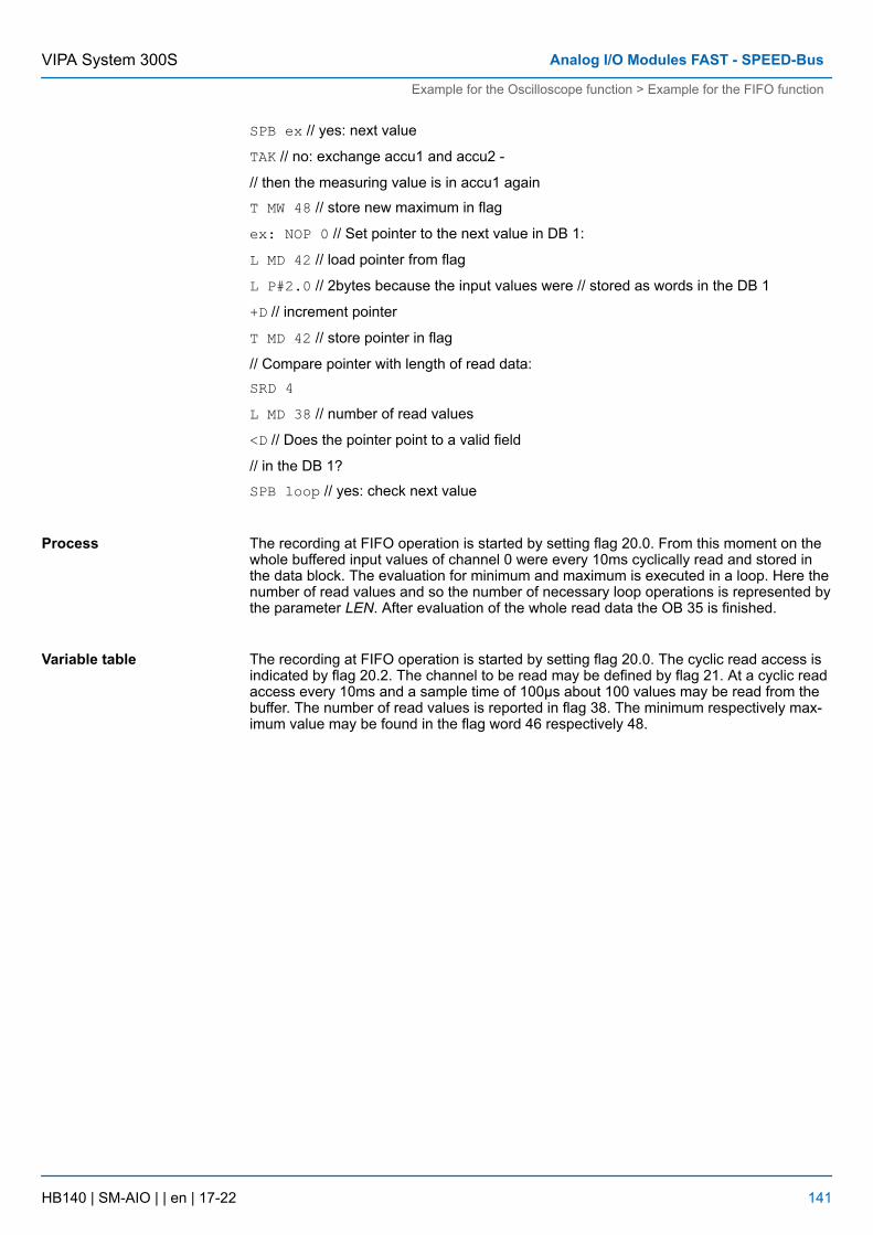
SPB ex // yes: next value
TAK // no: exchange accu1 and accu2 -
// then the measuring value is in accu1 again
T MW 48 // store new maximum in flag
ex: NOP 0 // Set pointer to the next value in DB 1:
L MD 42 // load pointer from flag
L P#2.0 // 2bytes because the input values were // stored as words in the DB 1
+D // increment pointer
T MD 42 // store pointer in flag
// Compare pointer with length of read data:SRD 4L MD 38 // number of read values
<D // Does the pointer point to a valid field
// in the DB 1?
SPB loop // yes: check next value
The recording at FIFO operation is started by setting flag 20.0. From this moment on thewhole buffered input values of channel 0 were every 10ms cyclically read and stored inthe data block. The evaluation for minimum and maximum is executed in a loop. Here thenumber of read values and so the number of necessary loop operations is represented bythe parameter LEN. After evaluation of the whole read data the OB 35 is finished.
The recording at FIFO operation is started by setting flag 20.0. The cyclic read access isindicated by flag 20.2. The channel to be read may be defined by flag 21. At a cyclic readaccess every 10ms and a sample time of 100µs about 100 values may be read from thebuffer. The number of read values is reported in flag 38. The minimum respectively max-imum value may be found in the flag word 46 respectively 48.
Process
Variable table
VIPA System 300S Analog I/O Modules FAST - SPEED-Bus
Example for the Oscilloscope function > Example for the FIFO function
HB140 | SM-AIO | | en | 17-22 141
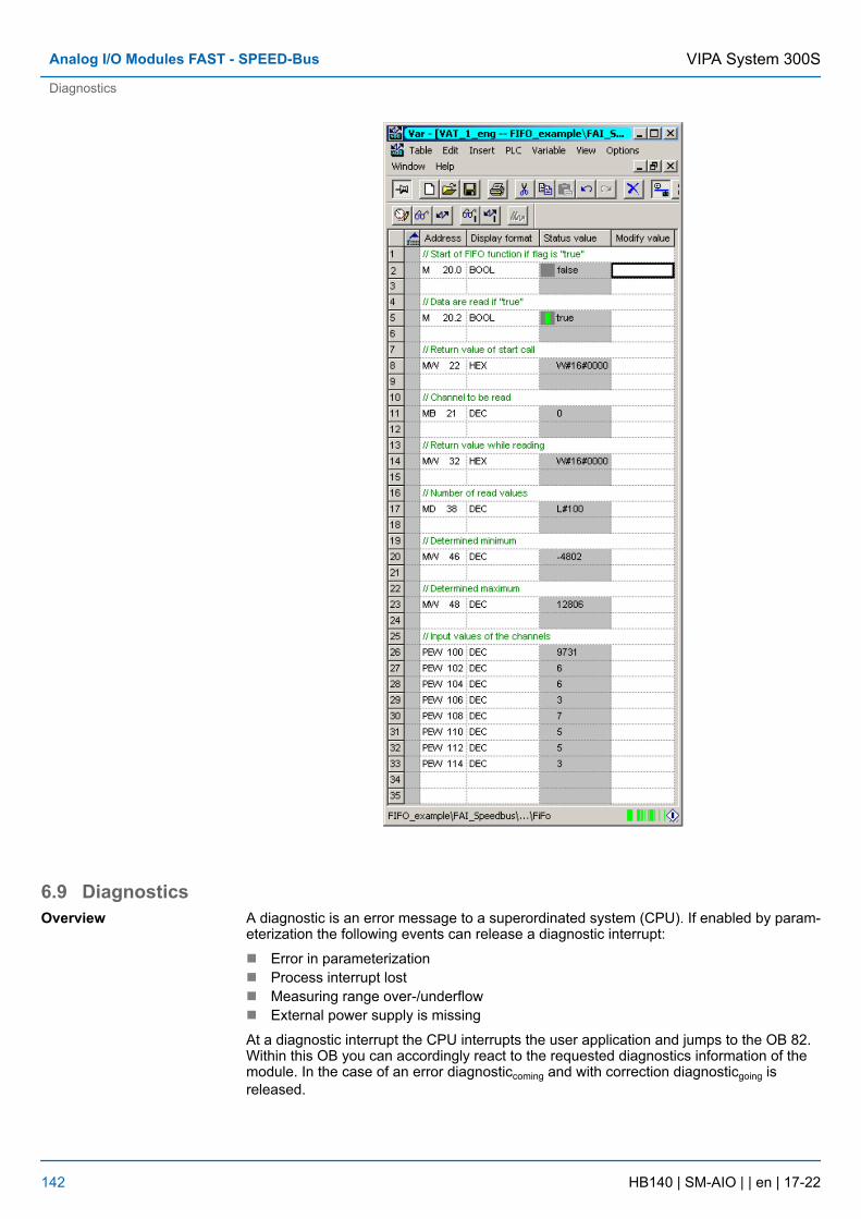
6.9 DiagnosticsA diagnostic is an error message to a superordinated system (CPU). If enabled by param-eterization the following events can release a diagnostic interrupt:
n Error in parameterizationn Process interrupt lostn Measuring range over-/underflown External power supply is missing
At a diagnostic interrupt the CPU interrupts the user application and jumps to the OB 82.Within this OB you can accordingly react to the requested diagnostics information of themodule. In the case of an error diagnosticcoming and with correction diagnosticgoing isreleased.
Overview
VIPA System 300SAnalog I/O Modules FAST - SPEED-Bus
Diagnostics
HB140 | SM-AIO | | en | 17-22 142
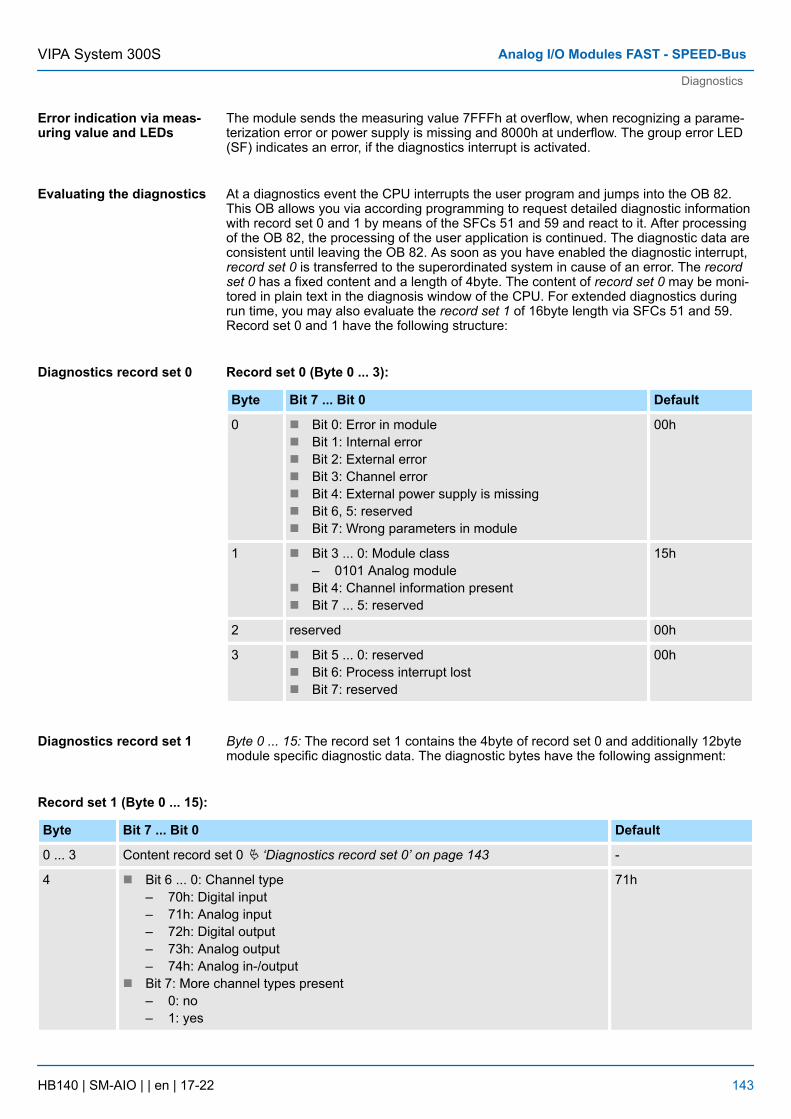
The module sends the measuring value 7FFFh at overflow, when recognizing a parame-terization error or power supply is missing and 8000h at underflow. The group error LED(SF) indicates an error, if the diagnostics interrupt is activated.
At a diagnostics event the CPU interrupts the user program and jumps into the OB 82.This OB allows you via according programming to request detailed diagnostic informationwith record set 0 and 1 by means of the SFCs 51 and 59 and react to it. After processingof the OB 82, the processing of the user application is continued. The diagnostic data areconsistent until leaving the OB 82. As soon as you have enabled the diagnostic interrupt,record set 0 is transferred to the superordinated system in cause of an error. The recordset 0 has a fixed content and a length of 4byte. The content of record set 0 may be moni-tored in plain text in the diagnosis window of the CPU. For extended diagnostics duringrun time, you may also evaluate the record set 1 of 16byte length via SFCs 51 and 59.Record set 0 and 1 have the following structure:
Record set 0 (Byte 0 ... 3):
Byte Bit 7 ... Bit 0 Default
0 n Bit 0: Error in modulen Bit 1: Internal errorn Bit 2: External errorn Bit 3: Channel errorn Bit 4: External power supply is missingn Bit 6, 5: reservedn Bit 7: Wrong parameters in module
00h
1 n Bit 3 ... 0: Module class– 0101 Analog module
n Bit 4: Channel information presentn Bit 7 ... 5: reserved
15h
2 reserved 00h
3 n Bit 5 ... 0: reservedn Bit 6: Process interrupt lostn Bit 7: reserved
00h
Byte 0 ... 15: The record set 1 contains the 4byte of record set 0 and additionally 12bytemodule specific diagnostic data. The diagnostic bytes have the following assignment:
Record set 1 (Byte 0 ... 15):
Byte Bit 7 ... Bit 0 Default
0 ... 3 Content record set 0 Ä ‘Diagnostics record set 0’ on page 143 -
4 n Bit 6 ... 0: Channel type– 70h: Digital input– 71h: Analog input– 72h: Digital output– 73h: Analog output– 74h: Analog in-/output
n Bit 7: More channel types present– 0: no– 1: yes
71h
Error indication via meas-uring value and LEDs
Evaluating the diagnostics
Diagnostics record set 0
Diagnostics record set 1
VIPA System 300S Analog I/O Modules FAST - SPEED-Bus
Diagnostics
HB140 | SM-AIO | | en | 17-22 143
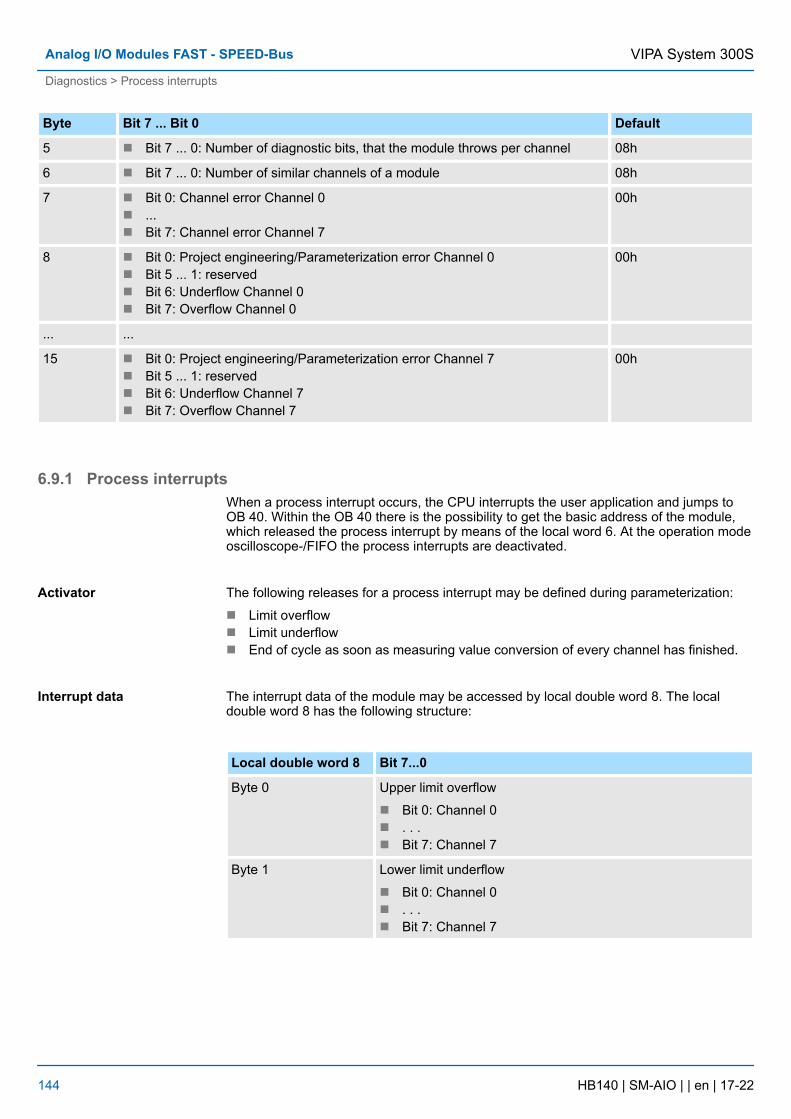
Byte Bit 7 ... Bit 0 Default
5 n Bit 7 ... 0: Number of diagnostic bits, that the module throws per channel 08h
6 n Bit 7 ... 0: Number of similar channels of a module 08h
7 n Bit 0: Channel error Channel 0n ...n Bit 7: Channel error Channel 7
00h
8 n Bit 0: Project engineering/Parameterization error Channel 0n Bit 5 ... 1: reservedn Bit 6: Underflow Channel 0n Bit 7: Overflow Channel 0
00h
... ...
15 n Bit 0: Project engineering/Parameterization error Channel 7n Bit 5 ... 1: reservedn Bit 6: Underflow Channel 7n Bit 7: Overflow Channel 7
00h
6.9.1 Process interruptsWhen a process interrupt occurs, the CPU interrupts the user application and jumps toOB 40. Within the OB 40 there is the possibility to get the basic address of the module,which released the process interrupt by means of the local word 6. At the operation modeoscilloscope-/FIFO the process interrupts are deactivated.
The following releases for a process interrupt may be defined during parameterization:
n Limit overflown Limit underflown End of cycle as soon as measuring value conversion of every channel has finished.
The interrupt data of the module may be accessed by local double word 8. The localdouble word 8 has the following structure:
Local double word 8 Bit 7...0
Byte 0 Upper limit overflow
n Bit 0: Channel 0n . . .n Bit 7: Channel 7
Byte 1 Lower limit underflow
n Bit 0: Channel 0n . . .n Bit 7: Channel 7
Activator
Interrupt data
VIPA System 300SAnalog I/O Modules FAST - SPEED-Bus
Diagnostics > Process interrupts
HB140 | SM-AIO | | en | 17-22 144
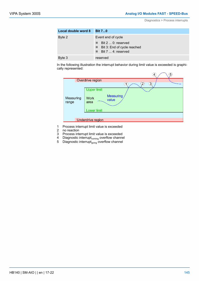
Local double word 8 Bit 7...0
Byte 2 Event end of cycle
n Bit 2 ... 0: reservedn Bit 3: End of cycle reachedn Bit 7 ... 4: reserved
Byte 3 reserved
In the following illustration the interrupt behavior during limit value is exceeded is graphi-cally represented:
1 Process interrupt limit value is exceeded2 no reaction3 Process interrupt limit value is exceeded4 Diagnostic interruptcoming overflow channel5 Diagnostic interruptgoing overflow channel
VIPA System 300S Analog I/O Modules FAST - SPEED-Bus
Diagnostics > Process interrupts
HB140 | SM-AIO | | en | 17-22 145

6.10 331-7AF70 - AI 8x16Bit IThe analog input modules transform analog signals from the process into digital signalsfor the internal processing. The modules are preset to one measuring range.
n 8 inputsn Oscilloscope-/FIFO-Function parameterizablen The 8 inputs are read synchronousn Measuring value resolution 15bit + signn Suitable for sensors ±20mAn Parameterizable diagnostic and process interruptn Isolated to the backplane bus and between the channels
After PowerON the diagnostics function of every channel is deactivated.
1 LEDs2 flap with labeling strip3 contact bar4 flap opened with inner label
Properties
Default settings
Structure
VIPA System 300SAnalog I/O Modules FAST - SPEED-Bus
331-7AF70 - AI 8x16Bit I
HB140 | SM-AIO | | en | 17-22 146
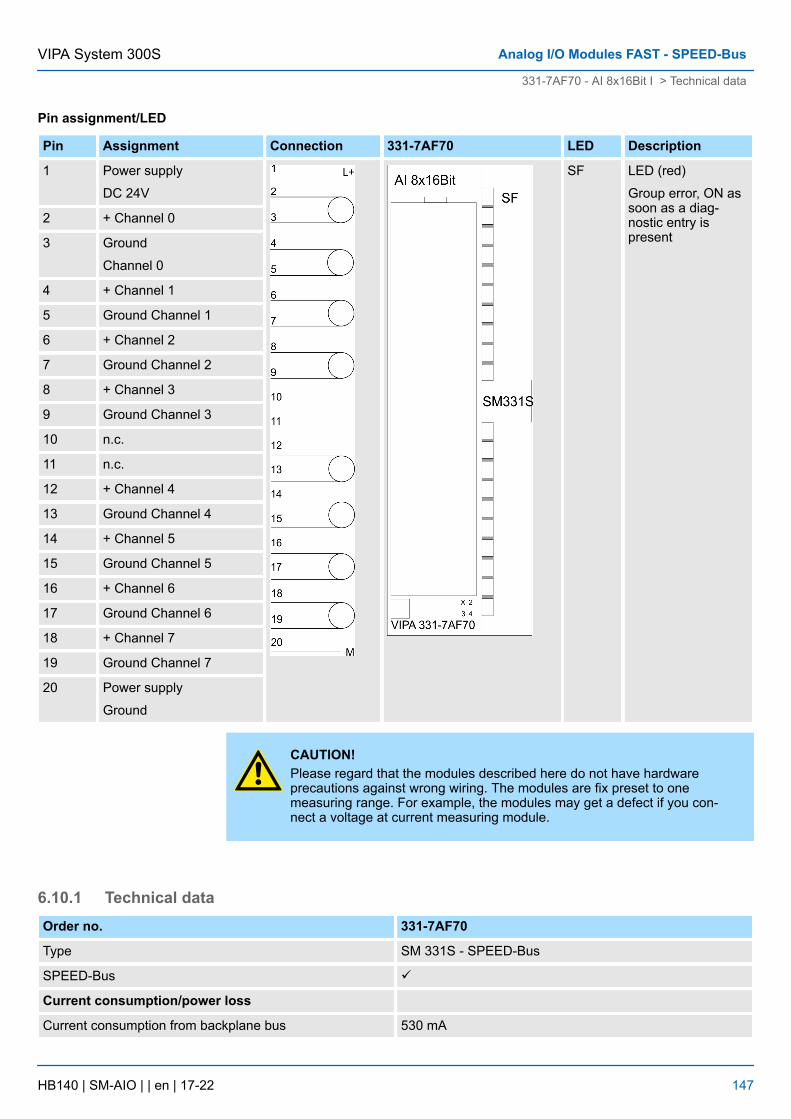
Pin assignment/LED
Pin Assignment Connection 331-7AF70 LED Description
1 Power supply
DC 24V
SF LED (red)
Group error, ON assoon as a diag-nostic entry ispresent
2 + Channel 0
3 Ground
Channel 0
4 + Channel 1
5 Ground Channel 1
6 + Channel 2
7 Ground Channel 2
8 + Channel 3
9 Ground Channel 3
10 n.c.
11 n.c.
12 + Channel 4
13 Ground Channel 4
14 + Channel 5
15 Ground Channel 5
16 + Channel 6
17 Ground Channel 6
18 + Channel 7
19 Ground Channel 7
20 Power supply
Ground
CAUTION!Please regard that the modules described here do not have hardwareprecautions against wrong wiring. The modules are fix preset to onemeasuring range. For example, the modules may get a defect if you con-nect a voltage at current measuring module.
6.10.1 Technical dataOrder no. 331-7AF70
Type SM 331S - SPEED-Bus
SPEED-Bus ü
Current consumption/power loss
Current consumption from backplane bus 530 mA
VIPA System 300S Analog I/O Modules FAST - SPEED-Bus
331-7AF70 - AI 8x16Bit I > Technical data
HB140 | SM-AIO | | en | 17-22 147
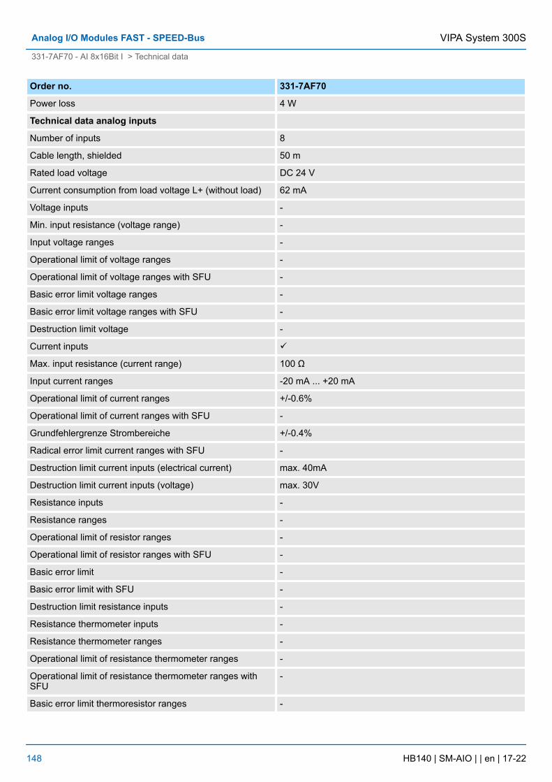
Order no. 331-7AF70
Power loss 4 W
Technical data analog inputs
Number of inputs 8
Cable length, shielded 50 m
Rated load voltage DC 24 V
Current consumption from load voltage L+ (without load) 62 mA
Voltage inputs -
Min. input resistance (voltage range) -
Input voltage ranges -
Operational limit of voltage ranges -
Operational limit of voltage ranges with SFU -
Basic error limit voltage ranges -
Basic error limit voltage ranges with SFU -
Destruction limit voltage -
Current inputs ü
Max. input resistance (current range) 100 Ω
Input current ranges -20 mA ... +20 mA
Operational limit of current ranges +/-0.6%
Operational limit of current ranges with SFU -
Grundfehlergrenze Strombereiche +/-0.4%
Radical error limit current ranges with SFU -
Destruction limit current inputs (electrical current) max. 40mA
Destruction limit current inputs (voltage) max. 30V
Resistance inputs -
Resistance ranges -
Operational limit of resistor ranges -
Operational limit of resistor ranges with SFU -
Basic error limit -
Basic error limit with SFU -
Destruction limit resistance inputs -
Resistance thermometer inputs -
Resistance thermometer ranges -
Operational limit of resistance thermometer ranges -
Operational limit of resistance thermometer ranges withSFU
-
Basic error limit thermoresistor ranges -
VIPA System 300SAnalog I/O Modules FAST - SPEED-Bus
331-7AF70 - AI 8x16Bit I > Technical data
HB140 | SM-AIO | | en | 17-22 148
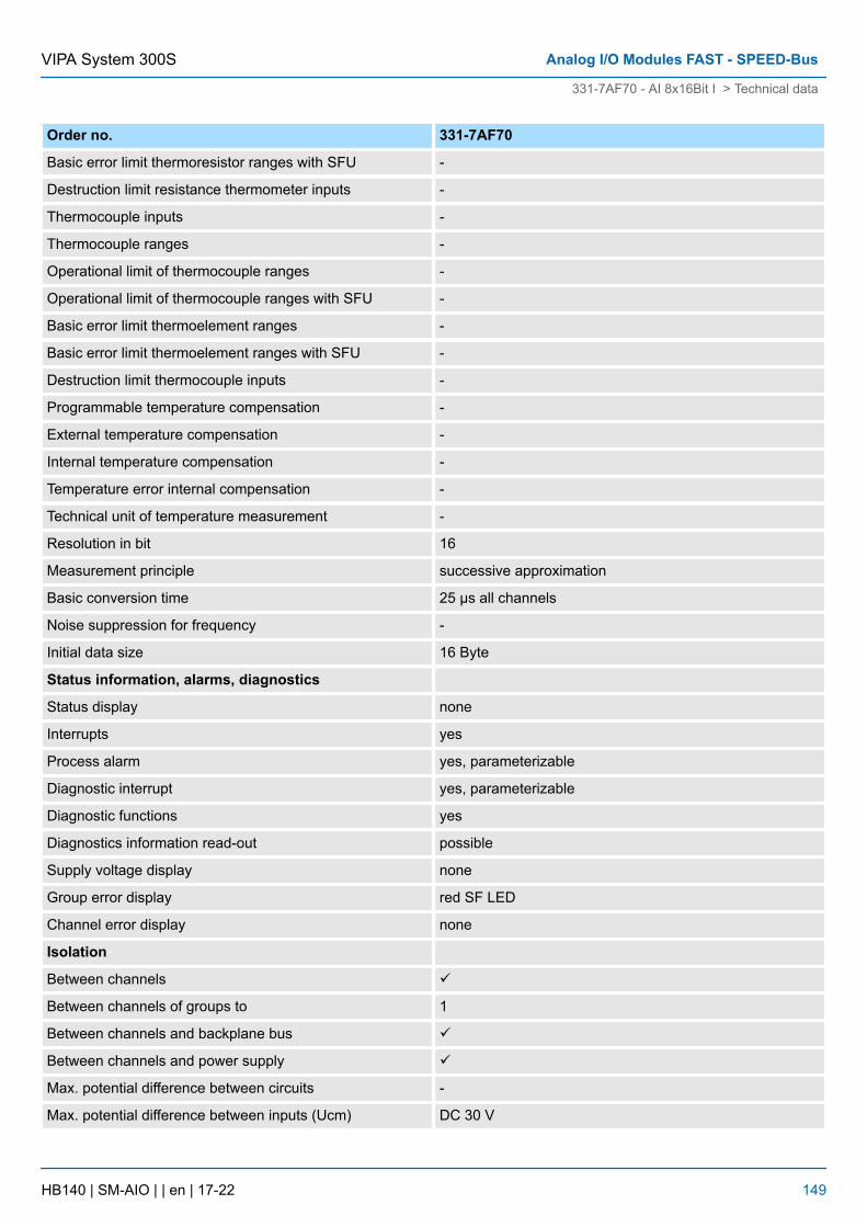
Order no. 331-7AF70
Basic error limit thermoresistor ranges with SFU -
Destruction limit resistance thermometer inputs -
Thermocouple inputs -
Thermocouple ranges -
Operational limit of thermocouple ranges -
Operational limit of thermocouple ranges with SFU -
Basic error limit thermoelement ranges -
Basic error limit thermoelement ranges with SFU -
Destruction limit thermocouple inputs -
Programmable temperature compensation -
External temperature compensation -
Internal temperature compensation -
Temperature error internal compensation -
Technical unit of temperature measurement -
Resolution in bit 16
Measurement principle successive approximation
Basic conversion time 25 µs all channels
Noise suppression for frequency -
Initial data size 16 Byte
Status information, alarms, diagnostics
Status display none
Interrupts yes
Process alarm yes, parameterizable
Diagnostic interrupt yes, parameterizable
Diagnostic functions yes
Diagnostics information read-out possible
Supply voltage display none
Group error display red SF LED
Channel error display none
Isolation
Between channels ü
Between channels of groups to 1
Between channels and backplane bus ü
Between channels and power supply ü
Max. potential difference between circuits -
Max. potential difference between inputs (Ucm) DC 30 V
VIPA System 300S Analog I/O Modules FAST - SPEED-Bus
331-7AF70 - AI 8x16Bit I > Technical data
HB140 | SM-AIO | | en | 17-22 149
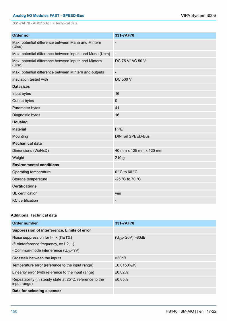
Order no. 331-7AF70
Max. potential difference between Mana and Mintern(Uiso)
-
Max. potential difference between inputs and Mana (Ucm) -
Max. potential difference between inputs and Mintern(Uiso)
DC 75 V/ AC 50 V
Max. potential difference between Mintern and outputs -
Insulation tested with DC 500 V
Datasizes
Input bytes 16
Output bytes 0
Parameter bytes 41
Diagnostic bytes 16
Housing
Material PPE
Mounting DIN rail SPEED-Bus
Mechanical data
Dimensions (WxHxD) 40 mm x 125 mm x 120 mm
Weight 210 g
Environmental conditions
Operating temperature 0 °C to 60 °C
Storage temperature -25 °C to 70 °C
Certifications
UL certification yes
KC certification -
Additional Technical data
Order number 331-7AF70
Suppression of interference, Limits of error
Noise suppression for f=nx (f1±1%)
(f1=Interference frequency, n=1,2,...)
- Common-mode interference (UCM<?V)
(UCM<20V) >80dB
Crosstalk between the inputs >50dB
Temperature error (reference to the input range) ±0.0150%/K
Linearity error (with reference to the input range) ±0.02%
Repeatability (in steady state at 25°C, reference to theinput range)
±0.05%
Data for selecting a sensor
VIPA System 300SAnalog I/O Modules FAST - SPEED-Bus
331-7AF70 - AI 8x16Bit I > Technical data
HB140 | SM-AIO | | en | 17-22 150
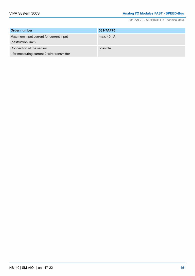
Order number 331-7AF70
Maximum input current for current input
(destruction limit)
max. 40mA
Connection of the sensor
- for measuring current 2-wire transmitter
possible
VIPA System 300S Analog I/O Modules FAST - SPEED-Bus
331-7AF70 - AI 8x16Bit I > Technical data
HB140 | SM-AIO | | en | 17-22 151
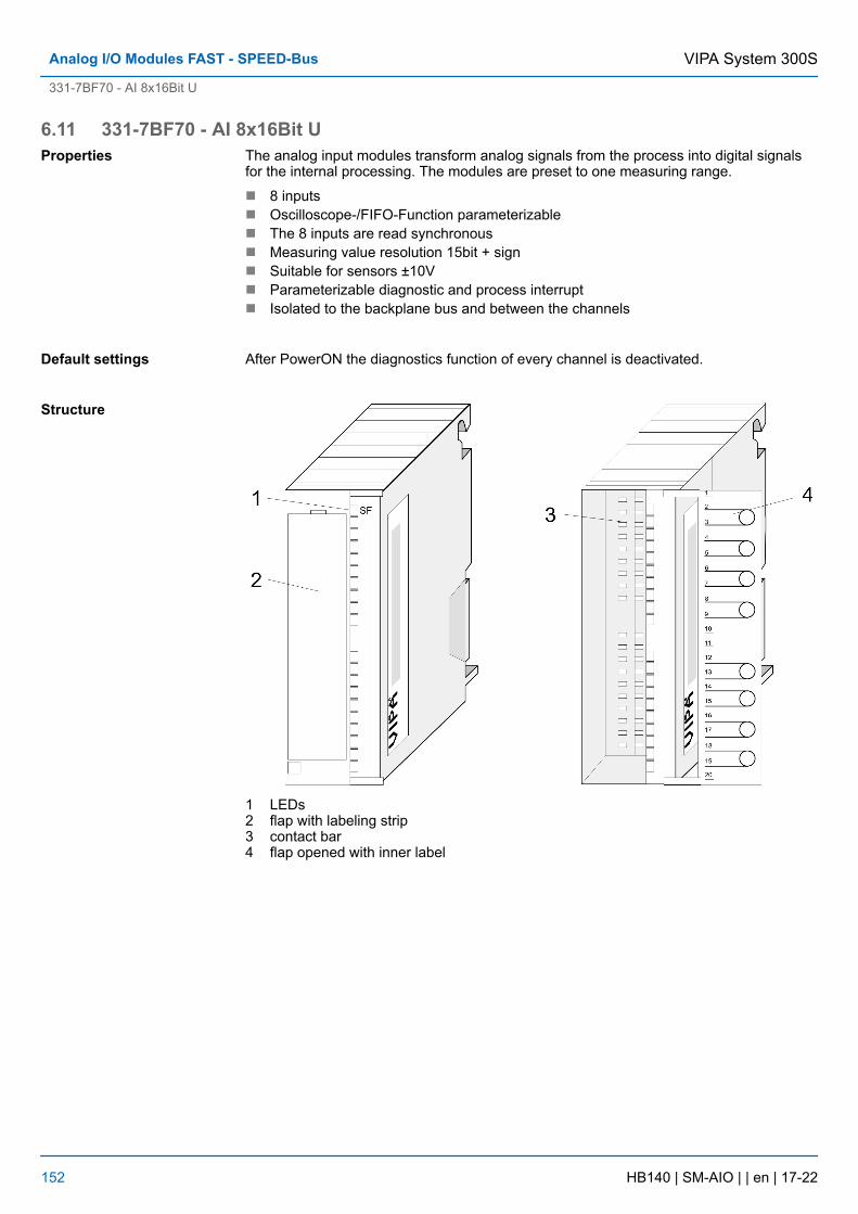
6.11 331-7BF70 - AI 8x16Bit UThe analog input modules transform analog signals from the process into digital signalsfor the internal processing. The modules are preset to one measuring range.
n 8 inputsn Oscilloscope-/FIFO-Function parameterizablen The 8 inputs are read synchronousn Measuring value resolution 15bit + signn Suitable for sensors ±10Vn Parameterizable diagnostic and process interruptn Isolated to the backplane bus and between the channels
After PowerON the diagnostics function of every channel is deactivated.
1 LEDs2 flap with labeling strip3 contact bar4 flap opened with inner label
Properties
Default settings
Structure
VIPA System 300SAnalog I/O Modules FAST - SPEED-Bus
331-7BF70 - AI 8x16Bit U
HB140 | SM-AIO | | en | 17-22 152
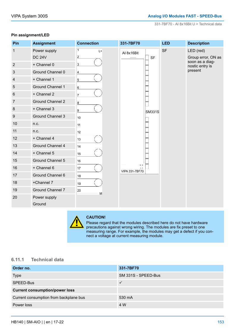
Pin assignment/LED
Pin Assignment Connection 331-7BF70 LED Description
1 Power supply
DC 24V
SF LED (red)
Group error, ON assoon as a diag-nostic entry ispresent
2 + Channel 0
3 Ground Channel 0
4 + Channel 1
5 Ground Channel 1
6 + Channel 2
7 Ground Channel 2
8 + Channel 3
9 Ground Channel 3
10 n.c.
11 n.c.
12 + Channel 4
13 Ground Channel 4
14 + Channel 5
15 Ground Channel 5
16 + Channel 6
17 Ground Channel 6
18 +Channel 7
19 Ground Channel 7
20 Power supply
Ground
CAUTION!Please regard that the modules described here do not have hardwareprecautions against wrong wiring. The modules are fix preset to onemeasuring range. For example, the modules may get a defect if you con-nect a voltage at current measuring module.
6.11.1 Technical dataOrder no. 331-7BF70
Type SM 331S - SPEED-Bus
SPEED-Bus ü
Current consumption/power loss
Current consumption from backplane bus 530 mA
Power loss 4 W
VIPA System 300S Analog I/O Modules FAST - SPEED-Bus
331-7BF70 - AI 8x16Bit U > Technical data
HB140 | SM-AIO | | en | 17-22 153
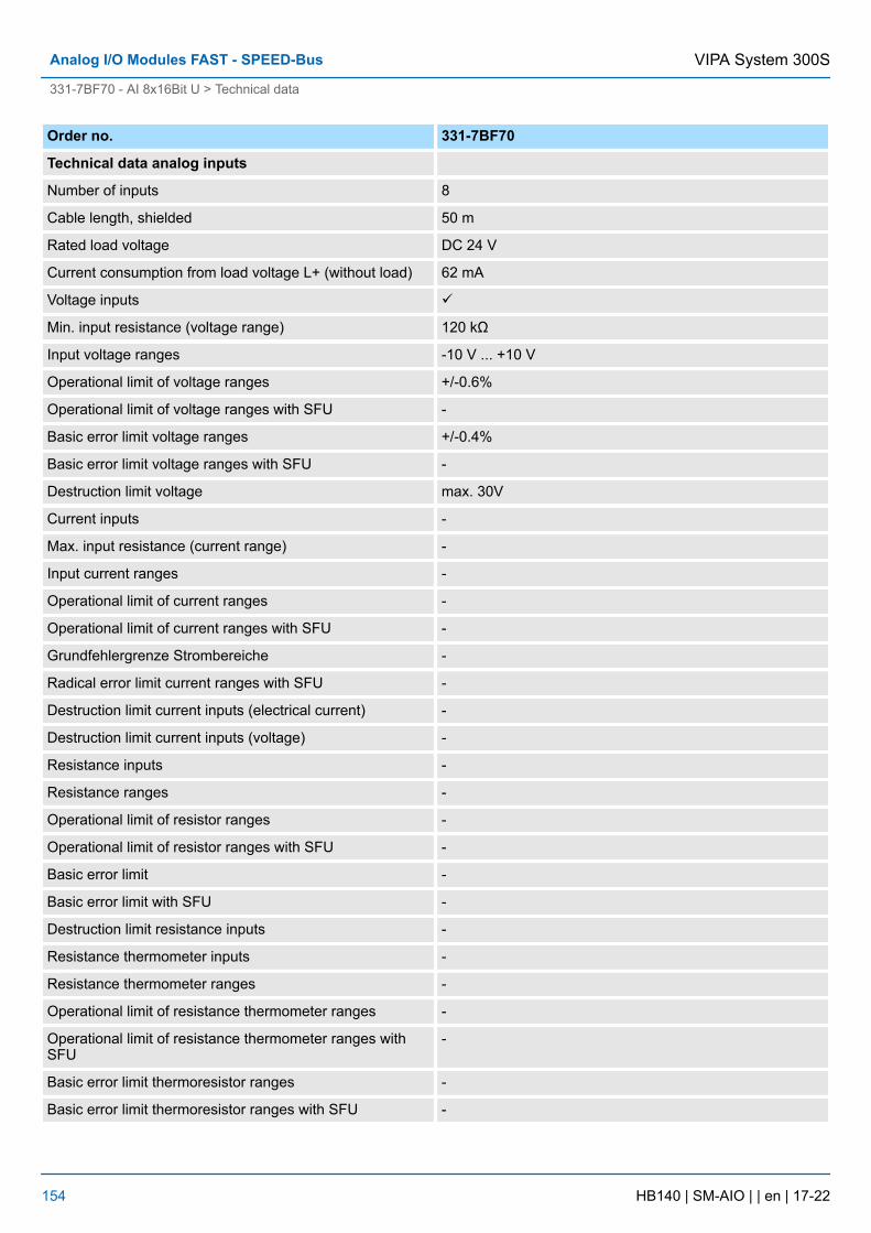
Order no. 331-7BF70
Technical data analog inputs
Number of inputs 8
Cable length, shielded 50 m
Rated load voltage DC 24 V
Current consumption from load voltage L+ (without load) 62 mA
Voltage inputs ü
Min. input resistance (voltage range) 120 kΩ
Input voltage ranges -10 V ... +10 V
Operational limit of voltage ranges +/-0.6%
Operational limit of voltage ranges with SFU -
Basic error limit voltage ranges +/-0.4%
Basic error limit voltage ranges with SFU -
Destruction limit voltage max. 30V
Current inputs -
Max. input resistance (current range) -
Input current ranges -
Operational limit of current ranges -
Operational limit of current ranges with SFU -
Grundfehlergrenze Strombereiche -
Radical error limit current ranges with SFU -
Destruction limit current inputs (electrical current) -
Destruction limit current inputs (voltage) -
Resistance inputs -
Resistance ranges -
Operational limit of resistor ranges -
Operational limit of resistor ranges with SFU -
Basic error limit -
Basic error limit with SFU -
Destruction limit resistance inputs -
Resistance thermometer inputs -
Resistance thermometer ranges -
Operational limit of resistance thermometer ranges -
Operational limit of resistance thermometer ranges withSFU
-
Basic error limit thermoresistor ranges -
Basic error limit thermoresistor ranges with SFU -
VIPA System 300SAnalog I/O Modules FAST - SPEED-Bus
331-7BF70 - AI 8x16Bit U > Technical data
HB140 | SM-AIO | | en | 17-22 154
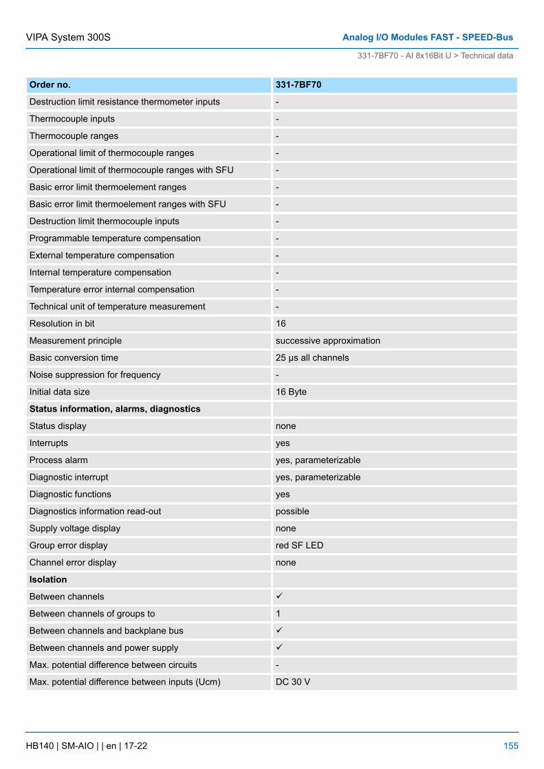
Order no. 331-7BF70
Destruction limit resistance thermometer inputs -
Thermocouple inputs -
Thermocouple ranges -
Operational limit of thermocouple ranges -
Operational limit of thermocouple ranges with SFU -
Basic error limit thermoelement ranges -
Basic error limit thermoelement ranges with SFU -
Destruction limit thermocouple inputs -
Programmable temperature compensation -
External temperature compensation -
Internal temperature compensation -
Temperature error internal compensation -
Technical unit of temperature measurement -
Resolution in bit 16
Measurement principle successive approximation
Basic conversion time 25 µs all channels
Noise suppression for frequency -
Initial data size 16 Byte
Status information, alarms, diagnostics
Status display none
Interrupts yes
Process alarm yes, parameterizable
Diagnostic interrupt yes, parameterizable
Diagnostic functions yes
Diagnostics information read-out possible
Supply voltage display none
Group error display red SF LED
Channel error display none
Isolation
Between channels ü
Between channels of groups to 1
Between channels and backplane bus ü
Between channels and power supply ü
Max. potential difference between circuits -
Max. potential difference between inputs (Ucm) DC 30 V
VIPA System 300S Analog I/O Modules FAST - SPEED-Bus
331-7BF70 - AI 8x16Bit U > Technical data
HB140 | SM-AIO | | en | 17-22 155

Order no. 331-7BF70
Max. potential difference between Mana and Mintern(Uiso)
-
Max. potential difference between inputs and Mana (Ucm) -
Max. potential difference between inputs and Mintern(Uiso)
DC 75 V/ AC 50 V
Max. potential difference between Mintern and outputs -
Insulation tested with DC 500 V
Datasizes
Input bytes 16
Output bytes 0
Parameter bytes 41
Diagnostic bytes 16
Housing
Material PPE
Mounting DIN rail SPEED-Bus
Mechanical data
Dimensions (WxHxD) 40 mm x 125 mm x 120 mm
Weight 210 g
Environmental conditions
Operating temperature 0 °C to 60 °C
Storage temperature -25 °C to 70 °C
Certifications
UL certification yes
KC certification -
Additional Technical data
Order number 331-7BF70
Suppression of interference, Limits of error
Noise suppression for f=nx (f1±1%)
(f1=Interference frequency, n=1,2,...)
- Common-mode interference (UCM< ?V)
(UCM<20V) >80dB
Crosstalk between the inputs >50dB
Temperature error (reference to the input range) ±0.0150%/K
Linearity error (with reference to the input range) ±0.02%
Repeatability (in steady state at 25°C, reference to the inputrange)
±0.05%
Data for selecting a sensor
VIPA System 300SAnalog I/O Modules FAST - SPEED-Bus
331-7BF70 - AI 8x16Bit U > Technical data
HB140 | SM-AIO | | en | 17-22 156
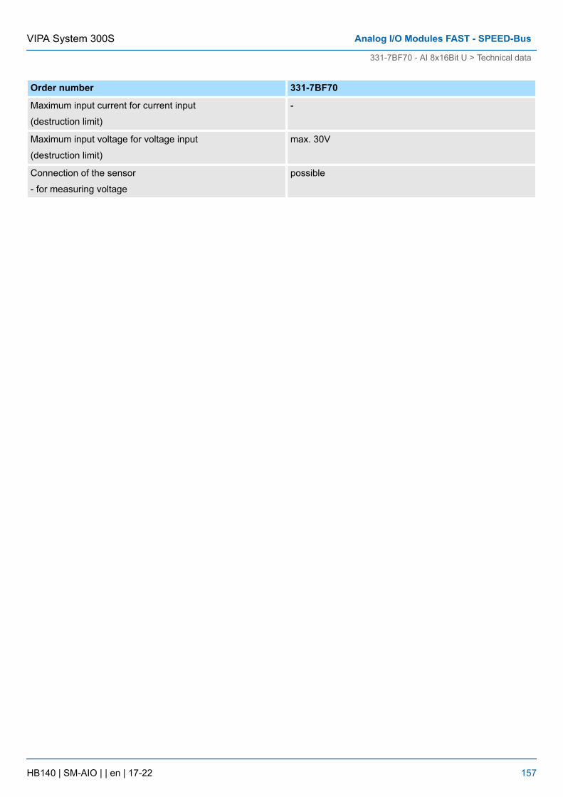
Order number 331-7BF70
Maximum input current for current input
(destruction limit)
-
Maximum input voltage for voltage input
(destruction limit)
max. 30V
Connection of the sensor
- for measuring voltage
possible
VIPA System 300S Analog I/O Modules FAST - SPEED-Bus
331-7BF70 - AI 8x16Bit U > Technical data
HB140 | SM-AIO | | en | 17-22 157