Embed Size (px)
DESCRIPTION
Vodia
Citation preview
i
VODIA User's Guide
© 2011 AB VOLVO PENTAAll rights to changes or modifications reserved.
ContentsAbout this Guide ��������������������������������������������������������������������������������������������������������� 4What is VODIA? ���������������������������������������������������������������������������������������������������������� 4
Which engines and control units does the VODIA Tool support? ��������������������������������������������� 4
Getting started ������������������������������������������������������������������������������������������������������������5Requirements ������������������������������������������������������������������������������������������������������������������������������������������5
Minimum requirements for VORP with communication jacket: .....................................................................................5Additional equipment depending on engine application:.............................................................................................................................................................................................5
VODIA connection options ������������������������������������������������������������������������������������������������������������������6Assemble the VODIA hardware ���������������������������������������������������������������������������������������������������������� 7
Connecting the communication jacket to the VODIA Tool ...............................................................................................7Connecting the VODIA Tool to the engine application ........................................................................................................7Requirements for PC hardware and software .............................................................................................................................8
How to get the VODIA Tool to function �����������������������������������������������������������������������������������������������������������������������������������������������������8Using the VODIA Tool for the first time ��������������������������������������������������������������������������������������������9
Performing a soft reset ..................................................................................................................................................................................9Using the PDA ......................................................................................................................................................................................................9Changing power settings ..........................................................................................................................................................................10
Connecting the VODIA Tool to a PC with Windows XP �������������������������������������������������������������10Setting up ActiveSync ..................................................................................................................................................................................10
Connecting the VODIA Tool to a PC with Windows Vista ���������������������������������������������������������11Install or update the VODIA Tool via the VODIA Web page �����������������������������������������������������12
Before getting started .................................................................................................................................................................................12Update the VODIA application ..............................................................................................................................................................13Update users .......................................................................................................................................................................................................13
VODIA overview ��������������������������������������������������������������������������������������������������������14The VODIA Today and TOOLS menu �����������������������������������������������������������������������������������������������14The VODIA Today functions���������������������������������������������������������������������������������������������������������������15
The TOOLS menu ������������������������������������������������������������������������������������������������������16Overview ������������������������������������������������������������������������������������������������������������������������������������������������16COM LOG �����������������������������������������������������������������������������������������������������������������������������������������������16
Record the log to a file: ..............................................................................................................................................................................16EVC System LCD Update �������������������������������������������������������������������������������������������������������������������16NMEA LOG ���������������������������������������������������������������������������������������������������������������������������������������������17
Record the log to a file: ..............................................................................................................................................................................17INTERFACE UPDATE ���������������������������������������������������������������������������������������������������������������������������17INFO ��������������������������������������������������������������������������������������������������������������������������������������������������������17
Application dialogues ����������������������������������������������������������������������������������������������18Enter VODIA for the first time �����������������������������������������������������������������������������������������������������������18
VODIA login ..........................................................................................................................................................................................................18Changing the VODIA application password ...............................................................................................................................18Run VODIA in simulator mode ..............................................................................................................................................................18Initiate and close simulator mode ......................................................................................................................................................18User groups ..........................................................................................................................................................................................................18
Connecting to the engine�������������������������������������������������������������������������������������������������������������������19Create a new job card ..................................................................................................................................................................................19Job cards on the VODIA Web ...............................................................................................................................................................19Select installation ............................................................................................................................................................................................20Detailed installation information ..........................................................................................................................................................21Select chassis ID .............................................................................................................................................................................................21
The menu structures��������������������������������������������������������������������������������������������������������������������������� 22VODIA Main menu ..........................................................................................................................................................................................22VODIA Function group menu .................................................................................................................................................................23Operations .............................................................................................................................................................................................................23VODIA application icons ............................................................................................................................................................................24Select function group ...................................................................................................................................................................................25
Function group - service and maintenance ���������������������������������������������������������������������������������� 25Error codes............................................................................................................................................................................................................26Parameter, programming ...........................................................................................................................................................................27ECU information, test ...................................................................................................................................................................................28Vessel configuration, test ..........................................................................................................................................................................28

ii
Sea trial, test ........................................................................................................................................................................................................28PDC, test ................................................................................................................................................................................................................28
Function group - Engine �������������������������������������������������������������������������������������������������������������������� 29Cylinder acceleration, test.........................................................................................................................................................................29Cylinder compression, test .......................................................................................................................................................................29Engine run-up, test .........................................................................................................................................................................................30Engine history, test .........................................................................................................................................................................................30Injectors shut off, manual (Diesel) .....................................................................................................................................................30MID 128 ECU, programming .................................................................................................................................................................31Gain & stability, calibration .......................................................................................................................................................................31Urea Dosing system, test ..........................................................................................................................................................................31Spark shut off, test .........................................................................................................................................................................................32Fuel pump relay, test .....................................................................................................................................................................................32Injectors shut off, manual (Petrol) ......................................................................................................................................................32Idle Air Control reset, test .........................................................................................................................................................................33Throttle activation, test ................................................................................................................................................................................33Cylinder Compression mode, test ......................................................................................................................................................33Idle speed control, test ................................................................................................................................................................................34Spark Fire, test ...................................................................................................................................................................................................34Injector control, test .......................................................................................................................................................................................34O2 sensor, test ..................................................................................................................................................................................................35Misfire reset, test..............................................................................................................................................................................................35
ECU programming ������������������������������������������������������������������������������������������������������������������������������� 36Central Systems ................................................................................................................................................................................................36Programming multiple installations ...................................................................................................................................................36The procedure ....................................................................................................................................................................................................36Detailed procedure .........................................................................................................................................................................................37HCU in service mode ...................................................................................................................................................................................37Campaign programming .............................................................................................................................................................................37
Function group - Electric control system and instruments������������������������������������������������������� 38MID 144 ECU, programming .................................................................................................................................................................38EVC system, programming .......................................................................................................................................................................38ACP Chassis ID, test .....................................................................................................................................................................................38ACP History, test ..............................................................................................................................................................................................38
Function group - Steering ����������������������������������������������������������������������������������������������������������������� 39Switching drive leg with the Automatic switchbox .....................................................................................................................................................................................39Explanation of buttons and illustrations ........................................................................................................................................39
Calibration ��������������������������������������������������������������������������������������������������������������������������������������������� 40OEM ............................................................................................................................................................................................................................40Drive replacement ...........................................................................................................................................................................................41
Configuration ��������������������������������������������������������������������������������������������������������������������������������������� 42Steering mode....................................................................................................................................................................................................42Docking force......................................................................................................................................................................................................42Dyn. Pos. System Force Factor .............................................................................................................................................................43
Test ��������������������������������������������������������������������������������������������������������������������������������������������������������� 43Alignment test ....................................................................................................................................................................................................43
The VODIA Web ��������������������������������������������������������������������������������������������������������44Overview ������������������������������������������������������������������������������������������������������������������������������������������������44The VODIA Web start page����������������������������������������������������������������������������������������������������������������44Update VODIA Tool �����������������������������������������������������������������������������������������������������������������������������44Order �������������������������������������������������������������������������������������������������������������������������������������������������������44VODIA ���������������������������������������������������������������������������������������������������������������������������������������������������� 45
Update users .......................................................................................................................................................................................................45ECU Programming ..........................................................................................................................................................................................45Invoices ....................................................................................................................................................................................................................46Report software .................................................................................................................................................................................................46Hardware Compatibility Map ..................................................................................................................................................................47Conversion/Accessory kit wizard ........................................................................................................................................................47Job card ...................................................................................................................................................................................................................47EGC .............................................................................................................................................................................................................................47IPS ...............................................................................................................................................................................................................................47Sea trial ....................................................................................................................................................................................................................47
PentaEDC1 ������������������������������������������������������������������������������������������������������������������������������������������� 48PentaMEFI �������������������������������������������������������������������������������������������������������������������������������������������� 48PentaEDC4 ������������������������������������������������������������������������������������������������������������������������������������������� 48Support �������������������������������������������������������������������������������������������������������������������������������������������������� 48
Support form........................................................................................................................................................................................................48Training .....................................................................................................................................................................................................................48Upgrade instruction .......................................................................................................................................................................................48Download Service Information ..............................................................................................................................................................48Manual ......................................................................................................................................................................................................................48FAQ .............................................................................................................................................................................................................................48
Web tools ���������������������������������������������������������������������������������������������������������������������������������������������� 49Reset VODIA application Password .................................................................................................................................................49

iii
Serial no/Chassis ID converter ...........................................................................................................................................................49Chassis ID info from VDA .........................................................................................................................................................................49Clean up ECU software ..............................................................................................................................................................................49VODIA offline installation ..........................................................................................................................................................................50User log ..................................................................................................................................................................................................................50
Support �����������������������������������������������������������������������������������������������������������������������51Get Log files, SSD file and Job card ������������������������������������������������������������������������������������������������51Attach files in Argus ����������������������������������������������������������������������������������������������������������������������������51
4
About this Guide
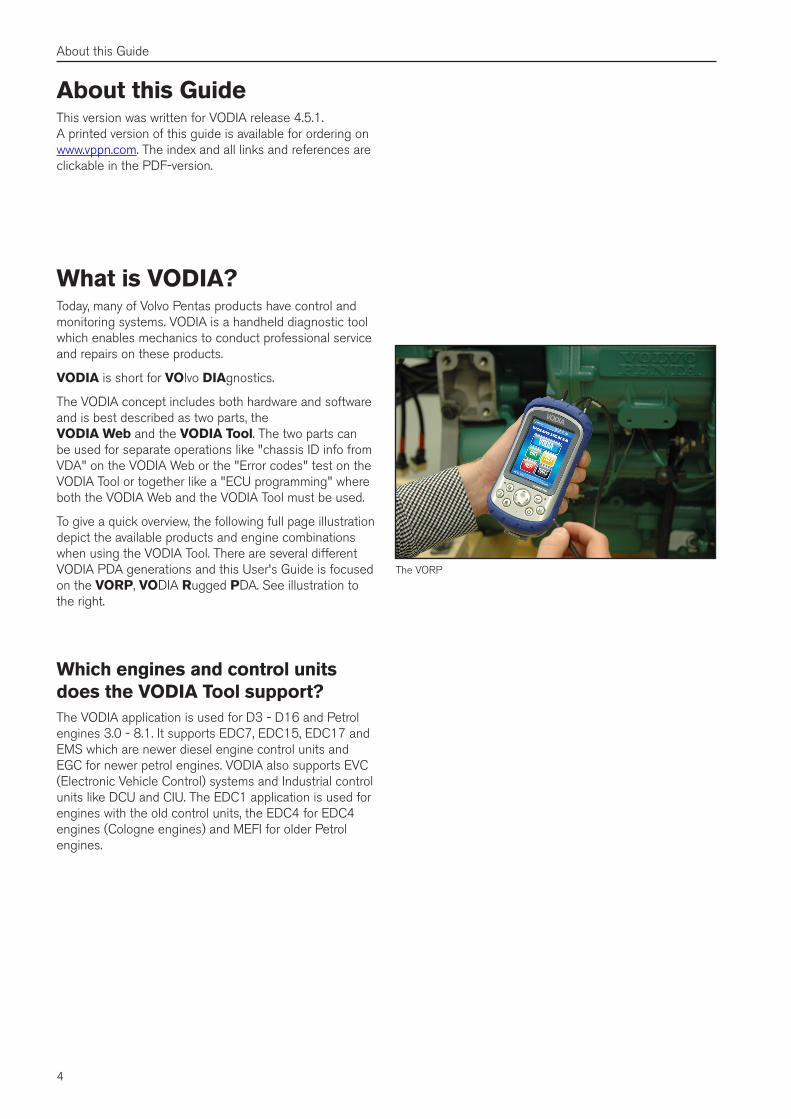
What is VODIA?Today, many of Volvo Pentas products have control and monitoring systems. VODIA is a handheld diagnostic tool which enables mechanics to conduct professional service and repairs on these products.
VODIA is short for VOlvo DIAgnostics.
The VODIA concept includes both hardware and software and is best described as two parts, the VODIA Web and the VODIA Tool. The two parts can be used for separate operations like "chassis ID info from VDA" on the VODIA Web or the "Error codes" test on the VODIA Tool or together like a "ECU programming" where both the VODIA Web and the VODIA Tool must be used.
To give a quick overview, the following full page illustration depict the available products and engine combinations when using the VODIA Tool. There are several different VODIA PDA generations and this User's Guide is focused on the VORP, VODIA Rugged PDA. See illustration to the right.
Which engines and control units does the VODIA Tool support?The VODIA application is used for D3 - D16 and Petrol engines 3.0 - 8.1. It supports EDC7, EDC15, EDC17 and EMS which are newer diesel engine control units and EGC for newer petrol engines. VODIA also supports EVC (Electronic Vehicle Control) systems and Industrial control units like DCU and CIU. The EDC1 application is used for engines with the old control units, the EDC4 for EDC4 engines (Cologne engines) and MEFI for older Petrol engines.
The VORP
About this GuideThis version was written for VODIA release 4.5.1. A printed version of this guide is available for ordering on www.vppn.com. The index and all links and references are clickable in the PDF-version.
5
Getting started
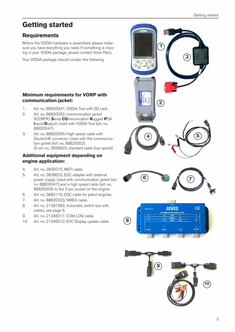
Getting startedRequirementsBefore the VODIA hardware is assembled, please make sure you have everything you need. If something is miss-ing in your VODIA package, please contact Volvo Parts.
Your VODIA package should contain the following:
8
76
4
2
1
3
5
10
9
Minimum requirements for VORP with communication jacket:
1. Art. no. 88820047, VODIA Tool with SD card. 2. Art. no. 88820052, communication jacket
SCORPIO Serial COmmunication Rugged PDA Input/Output). Used with VODIA Tool (art. no. 88820047).
3. Art. no. 88820059, High speed cable with Deutsch® connector. Used with the communica-tion jacket (Art. no. 88820052). Or art. no. 3838622, standard cable (low speed).
Additional equipment depending on engine application:
4. Art. no. 3839273, MEFI cable.5. Art. no. 3838623, EDC adapter with external
power supply. Used with communication jacket (art. no. 88820047) and a high speed cable (art. no. 88820059) to the 2-pin socket on the engine.
6. Art. no. 3883170, EGC cable for petrol engines.7. Art. no. 88820023, NMEA cable.8. Art. no. 21287382, Automatic switch box with
cables, see page 6.9. Art. no. 21346017, COM LOG cable.10. Art. no. 21346012, EVC Display update cable.
6
Getting started
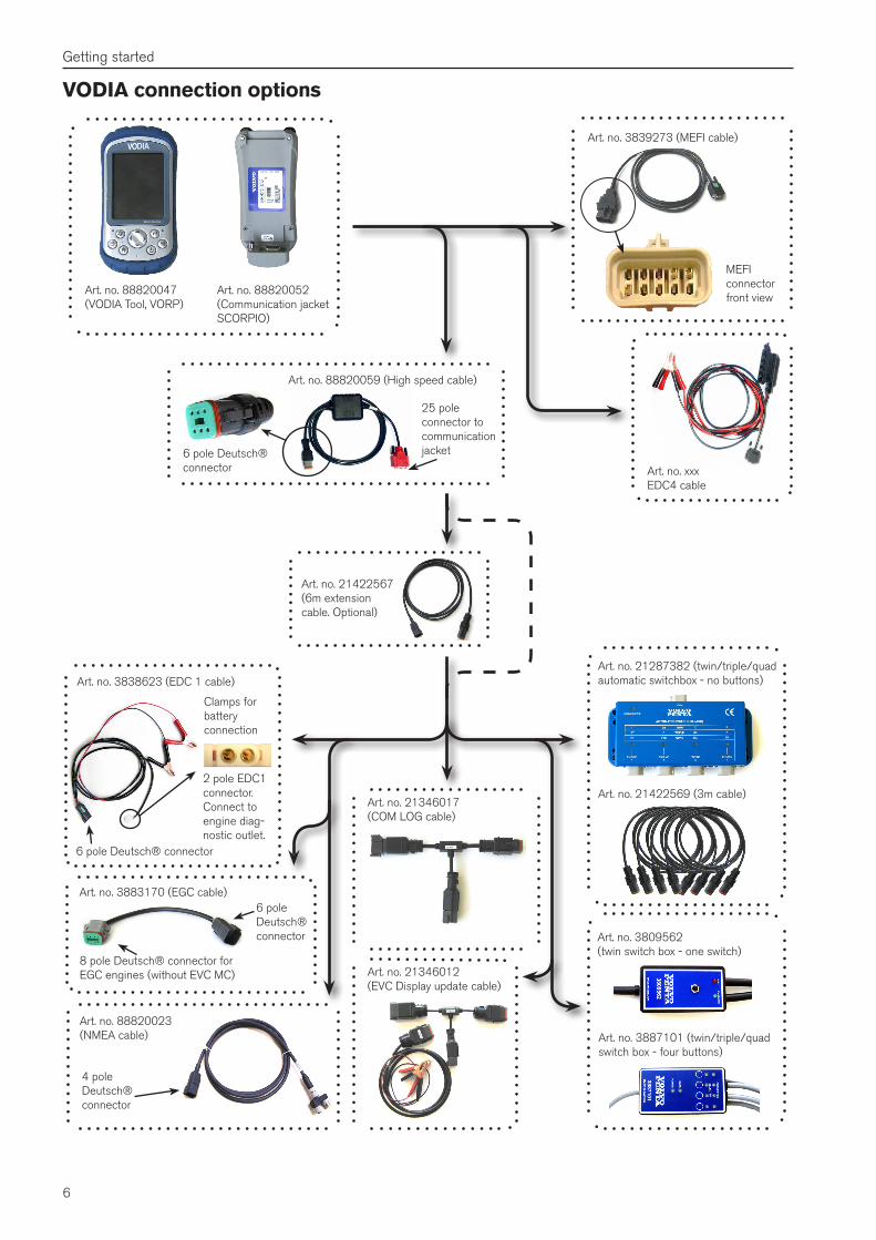
VODIA connection options
Art. no. 88820047 (VODIA Tool, VORP)
Art. no. 88820052 (Communication jacket SCORPIO)
Art. no. 3883170 (EGC cable)6 pole Deutsch®connector
8 pole Deutsch® connector for EGC engines (without EVC MC)
Art. no. 3809562 (twin switch box - one switch)
Art. no. 3887101 (twin/triple/quadswitch box - four buttons)
Art. no. 21287382 (twin/triple/quadautomatic switchbox - no buttons)
Art. no. 21422567(6m extension cable. Optional)
Art. no. 21422569 (3m cable)
Art. no. 3838623 (EDC 1 cable)
Clamps for battery connection
2 pole EDC1 connector. Connect to engine diag-nostic outlet.
6 pole Deutsch® connector
Art. no. 21346012 (EVC Display update cable)
Art. no. 21346017 (COM LOG cable)
Art. no. 88820023 (NMEA cable)
4 pole Deutsch®connector
Art. no. 88820059 (High speed cable)
25 pole connector to communication jacket6 pole Deutsch®
connector
Art. no. 3839273 (MEFI cable)
MEFIconnector front view
Art. no. xxxEDC4 cable
7
Getting started
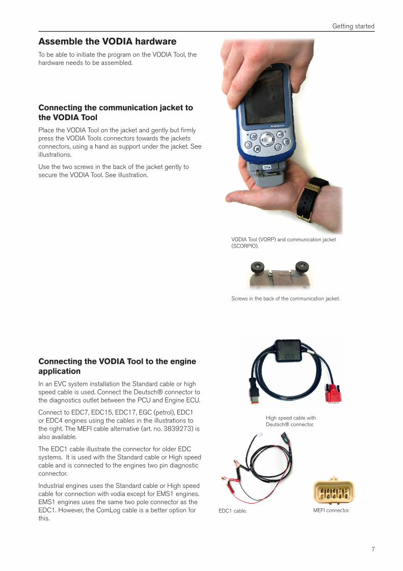
Assemble the VODIA hardwareTo be able to initiate the program on the VODIA Tool, the hardware needs to be assembled.
EDC1 cable.
VODIA Tool (VORP) and communication jacket (SCORPIO).
Screws in the back of the communication jacket.
High speed cable with Deutsch® connector.
MEFI connector.
Connecting the communication jacket to the VODIA Tool
Place the VODIA Tool on the jacket and gently but firmly press the VODIA Tools connectors towards the jackets connectors, using a hand as support under the jacket. See illustrations.
Use the two screws in the back of the jacket gently to secure the VODIA Tool. See illustration.
Connecting the VODIA Tool to the engine application
In an EVC system installation the Standard cable or high speed cable is used. Connect the Deutsch® connector to the diagnostics outlet between the PCU and Engine ECU.
Connect to EDC7, EDC15, EDC17, EGC (petrol), EDC1 or EDC4 engines using the cables in the illustrations to the right. The MEFI cable alternative (art. no. 3839273) is also available.
The EDC1 cable illustrate the connector for older EDC systems. It is used with the Standard cable or High speed cable and is connected to the engines two pin diagnostic connector.
Industrial engines uses the Standard cable or High speed cable for connection with vodia except for EMS1 engines. EMS1 engines uses the same two pole connector as the EDC1. However, the ComLog cable is a better option for this.
8
Getting started
Requirements for PC hardware and soft-ware• IBM-PC compatible personal computer.• Microsoft Windows® Vista or XP. • Microsoft Internet Explorer 6.0 or later with 128-bit
encryption.• USB port.• VGA graphics card or compatible video graphics
adapter at 256 colour or higher.• Keyboard.• Microsoft Mouse or compatible input device.• Hard drive with at least 200 MB of available hard
disk space.• Internet connection at a minimum speed of 0.5
Mbit/sec.
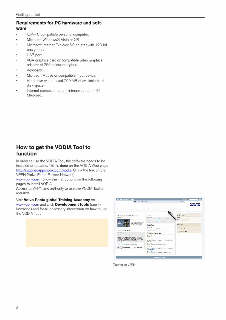
Training on VPPN
How to get the VODIA Tool to functionIn order to use the VODIA Tool, the software needs to be installed or updated. This is done on the VODIA Web page http://vppneuapps.volvo.com/vodia. Or via the link on the VPPN (Volvo Penta Partner Network) www.vppn.com. Follow the instructions on the following pages to install VODIA. Access to VPPN and authority to use the VODIA Tool is required.
Visit Volvo Penta global Training Academy on www.vppn.com and click Development tools (see il-lustration) and for all necessary information on how to use the VODIA Tool.
Note! It is not possible to use or run the VODIA Tool without having completed VODIA training. A VPPN user ID is also essential to be able to enter the VPPN web pages. If you don't have a VPPN user ID, please contact your local Volvo Penta support.
9
Getting started
Performing a soft reset
A soft reset can be compared to restarting a computer. This is helpful for instance if a communication problem has occurred.
To perform a soft reset:
Press the power button for ten seconds or until the screen goes dark. The VORP resets after a few seconds.
Performing a clean reset
Note! A clean reset clears all user-installed set-tings, programs and data, and it restores the VODIA Tool to factory settings. Save the files you want to keep on an external disk or the computer.
To perform a clean reset and return to factory settings for the VODIA Tool:
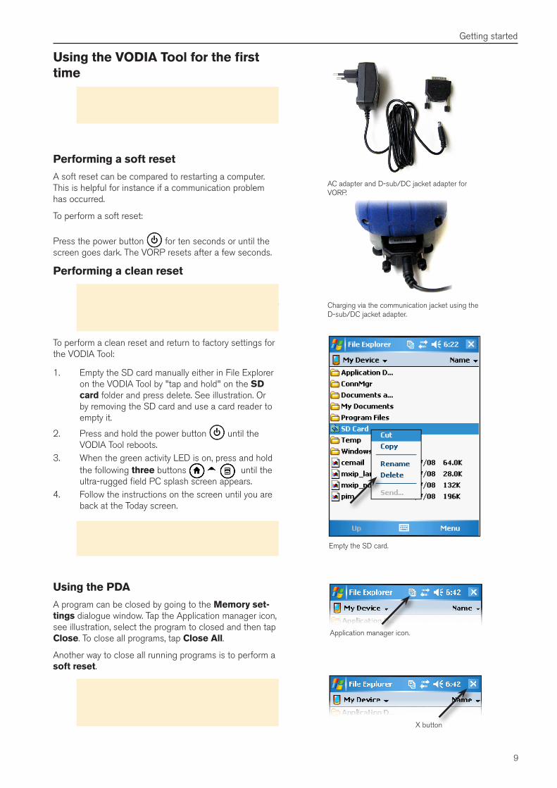
1. Empty the SD card manually either in File Explorer on the VODIA Tool by "tap and hold" on the SD card folder and press delete. See illustration. Or by removing the SD card and use a card reader to empty it.
2. Press and hold the power button until the VODIA Tool reboots.
3. When the green activity LED is on, press and hold the following three buttons until the ultra-rugged field PC splash screen appears.
4. Follow the instructions on the screen until you are back at the Today screen.
Important! Make sure that the time and date are set correctly in the PDA. Otherwise the wrong time and date will be written in the job cards.
Using the VODIA Tool for the first time
Important! The first time the VODIA application is started on a VODIA Tool, the AC adapter shall be used. See illustrations.
AC adapter and D-sub/DC jacket adapter for VORP.
Empty the SD card.
Charging via the communication jacket using the D-sub/DC jacket adapter.
X button
Application manager icon.
Using the PDA
A program can be closed by going to the Memory set-tings dialogue window. Tap the Application manager icon, see illustration, select the program to closed and then tap Close. To close all programs, tap Close All.
Another way to close all running programs is to perform a soft reset.
Note! When pressing the X button in the upper right corner of the VODIA Tool display (see illustra-tion), the program is not closed like in Windows XP and Vista etc, it is only minimized.
10
Getting started
Connecting the VODIA Tool to a PC with Windows XPSetting up ActiveSync
Install Microsoft ActiveSync from the included CD on the PC according to the instructions provided by the manufac-turer.
Important! Do not connect the VODIA Tool to the PC prior to installing ActiveSync. If so, old drivers will be used.
Perform the following steps to connect the VODIA Tool to the PC:
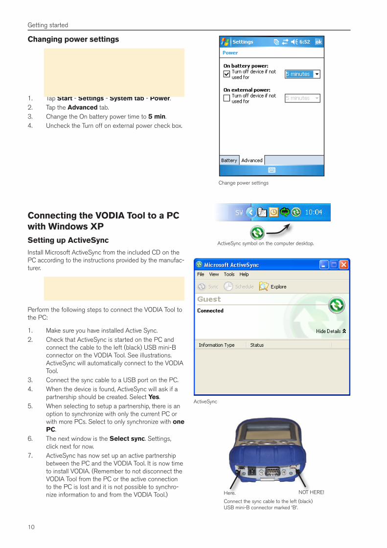
1. Make sure you have installed Active Sync.2. Check that ActiveSync is started on the PC and
connect the cable to the left (black) USB mini-B connector on the VODIA Tool. See illustrations. ActiveSync will automatically connect to the VODIA Tool.
3. Connect the sync cable to a USB port on the PC.4. When the device is found, ActiveSync will ask if a
partnership should be created. Select Yes.5. When selecting to setup a partnership, there is an
option to synchronize with only the current PC or with more PCs. Select to only synchronize with one PC.
6. The next window is the Select sync. Settings, click next for now.
7. ActiveSync has now set up an active partnership between the PC and the VODIA Tool. It is now time to install VODIA. (Remember to not disconnect the VODIA Tool from the PC or the active connection to the PC is lost and it is not possible to synchro-nize information to and from the VODIA Tool.)
ActiveSync symbol on the computer desktop.
Change power settings
ActiveSync
Connect the sync cable to the left (black) USB mini-B connector marked 'B'.
NOT HERE!Here.
Changing power settings
Important! Before you update the VODIA Tool you must change the power settings to ensure that the PDA doesn't go to suspend mode during the update. If not the installation might stop and the VODIA Tool could end up not working correctly.
1. Tap Start - Settings - System tab - Power.2. Tap the Advanced tab.3. Change the On battery power time to 5 min.4. Uncheck the Turn off on external power check box.
11
Getting started
Windows Mobile Device Center
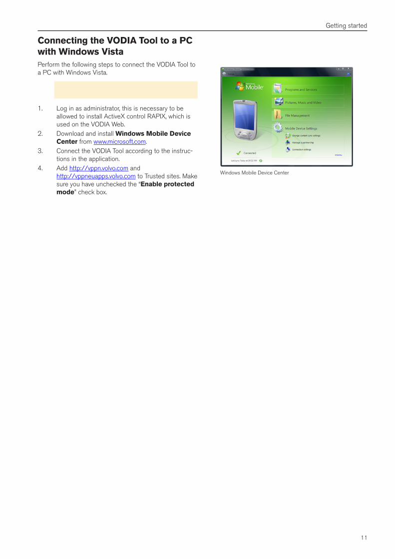
Connecting the VODIA Tool to a PC with Windows VistaPerform the following steps to connect the VODIA Tool to a PC with Windows Vista.
Note! Active Sync is replaced by Windows Mobile Device Center in Windows Vista.
1. Log in as administrator, this is necessary to be allowed to install ActiveX control RAPIX, which is used on the VODIA Web.
2. Download and install Windows Mobile Device Center from www.microsoft.com.
3. Connect the VODIA Tool according to the instruc-tions in the application.
4. Add http://vppn.volvo.com and http://vppneuapps.volvo.com to Trusted sites. Make sure you have unchecked the “Enable protected mode” check box.
12
Getting started
Install or update the VODIA Tool via the VODIA Web page Before getting started
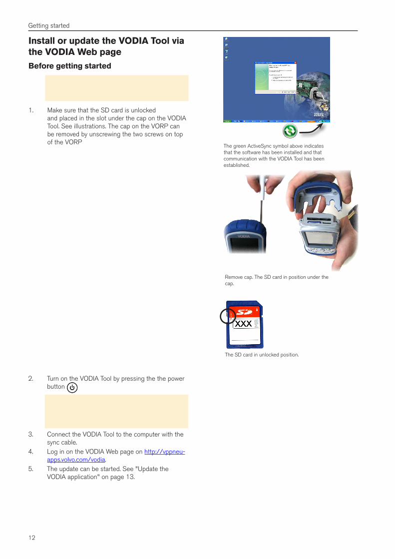
Important! The ActiveSync software must be installed on the computer before the VODIA Tool can be updated. See illustration.
1. Make sure that the SD card is unlocked and placed in the slot under the cap on the VODIA Tool. See illustrations. The cap on the VORP can be removed by unscrewing the two screws on top of the VORP
The green ActiveSync symbol above indicates that the software has been installed and that communication with the VODIA Tool has been established.
The SD card in unlocked position.
Remove cap. The SD card in position under the cap.
2. Turn on the VODIA Tool by pressing the the power button
Note! To save battery life. Press and hold the power button for about 4 seconds. A menu ap-pears. Tap Power off. To power on again, press the power button again.
3. Connect the VODIA Tool to the computer with the sync cable.
4. Log in on the VODIA Web page on http://vppneu-apps.volvo.com/vodia.
5. The update can be started. See "Update the VODIA application" on page 13.
13
Getting started
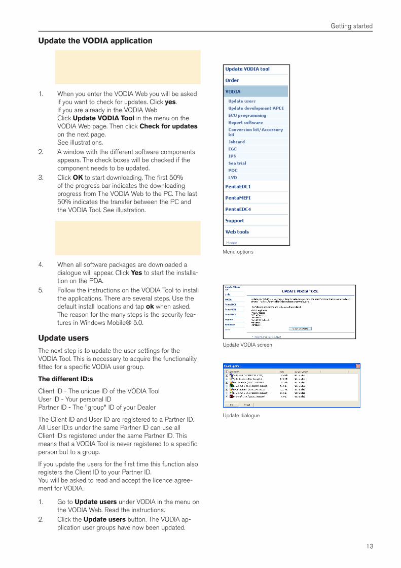
Menu options
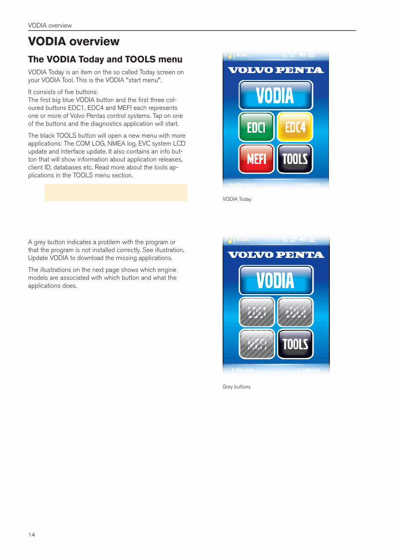
Update dialogue
Update the VODIA application
Important! Make sure that the VORP is on ex-ternal power and that you have the correct power settings before updating. See "Changing power settings" on page 10.
1. When you enter the VODIA Web you will be asked if you want to check for updates. Click yes. If you are already in the VODIA Web Click Update VODIA Tool in the menu on the VODIA Web page. Then click Check for updates on the next page. See illustrations.
2. A window with the different software components appears. The check boxes will be checked if the component needs to be updated.
3. Click OK to start downloading. The first 50% of the progress bar indicates the downloading progress from The VODIA Web to the PC. The last 50% indicates the transfer between the PC and the VODIA Tool. See illustration.
Important! The application package is approxi-mately 40 MB and it will take a while to download the. This also depends on the speed of the internet connection.
4. When all software packages are downloaded a dialogue will appear. Click Yes to start the installa-tion on the PDA.
5. Follow the instructions on the VODIA Tool to install the applications. There are several steps. Use the default install locations and tap ok when asked. The reason for the many steps is the security fea-tures in Windows Mobile® 5.0.
Update users
The next step is to update the user settings for the VODIA Tool. This is necessary to acquire the functionality fitted for a specific VODIA user group.
The different ID:s
Client ID - The unique ID of the VODIA Tool User ID - Your personal ID Partner ID - The "group" ID of your Dealer
The Client ID and User ID are registered to a Partner ID. All User ID:s under the same Partner ID can use all Client ID:s registered under the same Partner ID. This means that a VODIA Tool is never registered to a specific person but to a group.
If you update the users for the first time this function also registers the Client ID to your Partner ID. You will be asked to read and accept the licence agree-ment for VODIA.
1. Go to Update users under VODIA in the menu on the VODIA Web. Read the instructions.
2. Click the Update users button. The VODIA ap-plication user groups have now been updated.
Update VODIA screen
14
VODIA overview
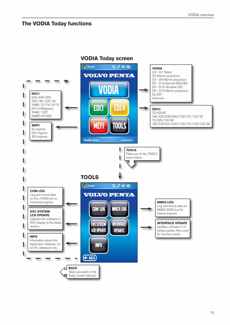
VODIA overviewThe VODIA Today and TOOLS menuVODIA Today is an item on the so called Today screen on your VODIA Tool. This is the VODIA "start menu".
It consists of five buttons: The first big blue VODIA button and the first three col-oured buttons EDC1, EDC4 and MEFI each represents one or more of Volvo Pentas control systems. Tap on one of the buttons and the diagnostics application will start.
The black TOOLS button will open a new menu with more applications: The COM LOG, NMEA log, EVC system LCD update and interface update. It also contains an info but-ton that will show information about application releases, client ID, databases etc. Read more about the tools ap-plications in the TOOLS menu section.
Note! For a PentaEDC1 manual, start the EDC1 application and press . VODIA Today
Grey buttons
A grey button indicates a problem with the program or that the program is not installed correctly. See illustration. Update VODIA to download the missing applications.
The illustrations on the next page shows which engine models are associated with which button and what the applications does.
15
VODIA overview
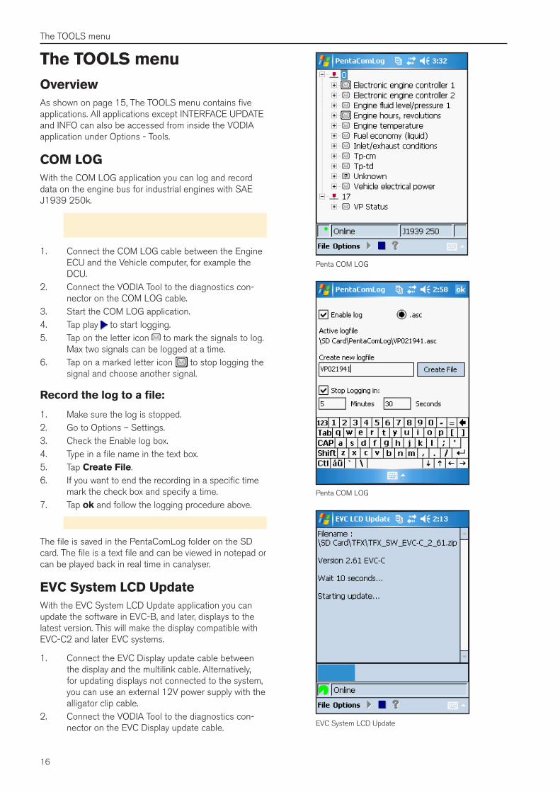
The VODIA Today functions
EDC4TD 420VETAD 420/520/620/720/721/722 VETD 520/720 GETAD 530/531/532/730/731/732/733 GE
EDC1KAD 44P/300TAD 740 1231 VETAMD 72/73/74/75DH10 (Railpack)TAMD 122PKAMD 44/300
MEFIGi enginesGXi enginesGSi engines
COM LOGLog and record data on the J1939 bus on Industrial engines.
EVC SYSTEMLCD UPDATEUpdates the software in EVC display to the latest version.
NMEA LOGLog and record data on NMEA 2000 bus for marine engines.
INTERFACE UPDATEUpdates software in in-terface jacket. Also used for function check.
INFOInformation about the Application releases, cli-ent ID, databases etc.
BACKTakes you back to the Today screen (above).
VODIA Today screen
TOOLS
VODIA3.0 - 8.1 PetrolD3 Marine propulsionD4 - D6 Marine propulsionD5 - D16 Genset (MG/GE)D5 - D16 Versatile (VE)D9 - D16 Marine propulsionQL ESTUnknown
TOOLSTakes you to the TOOLS menu below.
16
The TOOLS menu
The TOOLS menuOverviewAs shown on page 15, The TOOLS menu contains five applications. All applications except INTERFACE UPDATE and INFO can also be accessed from inside the VODIA application under Options - Tools.
COM LOGWith the COM LOG application you can log and record data on the engine bus for industrial engines with SAE J1939 250k.
Note! The COM LOG cable, art. no. 21346017 is essential for this procedure.
1. Connect the COM LOG cable between the Engine ECU and the Vehicle computer, for example the DCU.
2. Connect the VODIA Tool to the diagnostics con-nector on the COM LOG cable.
3. Start the COM LOG application.4. Tap play to start logging.5. Tap on the letter icon to mark the signals to log.
Max two signals can be logged at a time.6. Tap on a marked letter icon to stop logging the
signal and choose another signal.
Record the log to a file:
1. Make sure the log is stopped.2. Go to Options – Settings.3. Check the Enable log box.4. Type in a file name in the text box.5. Tap Create File.6. If you want to end the recording in a specific time
mark the check box and specify a time.7. Tap ok and follow the logging procedure above.
Note! The files get large quickly. 1 min ≈ 620kB
The file is saved in the PentaComLog folder on the SD card. The file is a text file and can be viewed in notepad or can be played back in real time in canalyser.
EVC System LCD UpdateWith the EVC System LCD Update application you can update the software in EVC-B, and later, displays to the latest version. This will make the display compatible with EVC-C2 and later EVC systems.
1. Connect the EVC Display update cable between the display and the multilink cable. Alternatively, for updating displays not connected to the system, you can use an external 12V power supply with the alligator clip cable.
2. Connect the VODIA Tool to the diagnostics con-nector on the EVC Display update cable.
Penta COM LOG
Penta COM LOG
EVC System LCD Update
17
The TOOLS menu
3. Start the EVC Display update application.4. Press play to start updating.
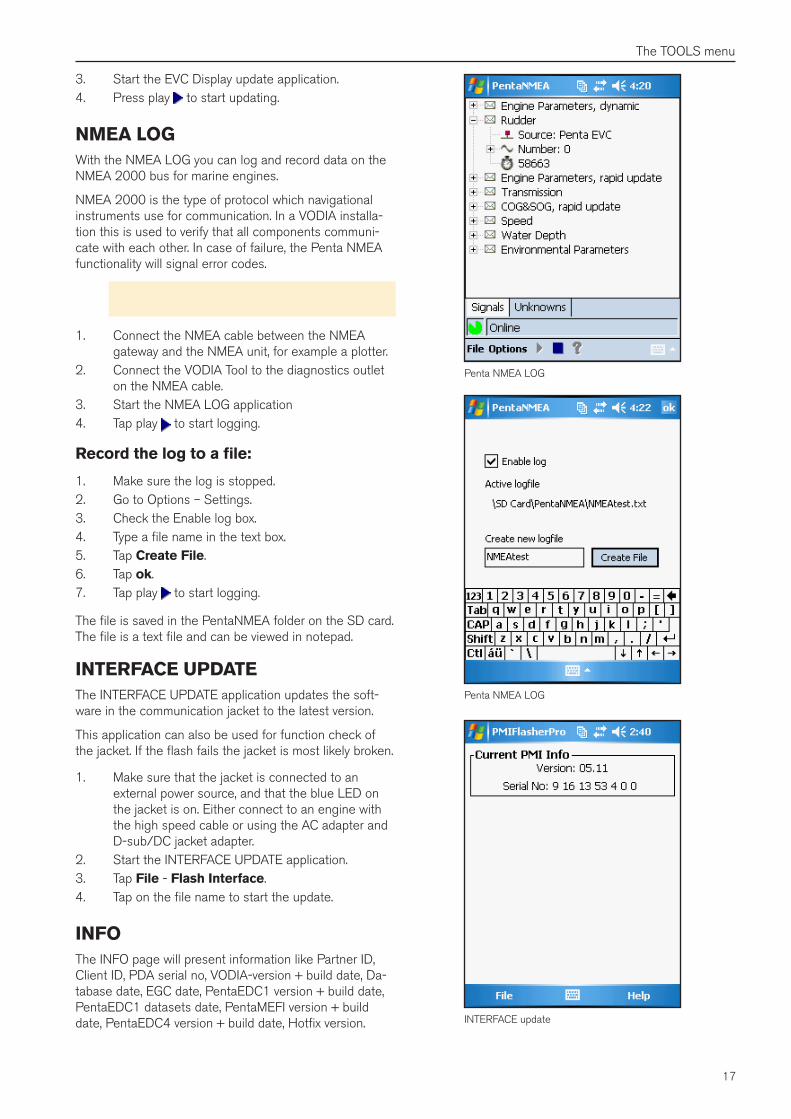
NMEA LOGWith the NMEA LOG you can log and record data on the NMEA 2000 bus for marine engines.
NMEA 2000 is the type of protocol which navigational instruments use for communication. In a VODIA installa-tion this is used to verify that all components communi-cate with each other. In case of failure, the Penta NMEA functionality will signal error codes.
Note! The NMEA cable, art. no. 88820023, is essential for this procedure.
1. Connect the NMEA cable between the NMEA gateway and the NMEA unit, for example a plotter.
2. Connect the VODIA Tool to the diagnostics outlet on the NMEA cable.
3. Start the NMEA LOG application4. Tap play to start logging.
Record the log to a file:
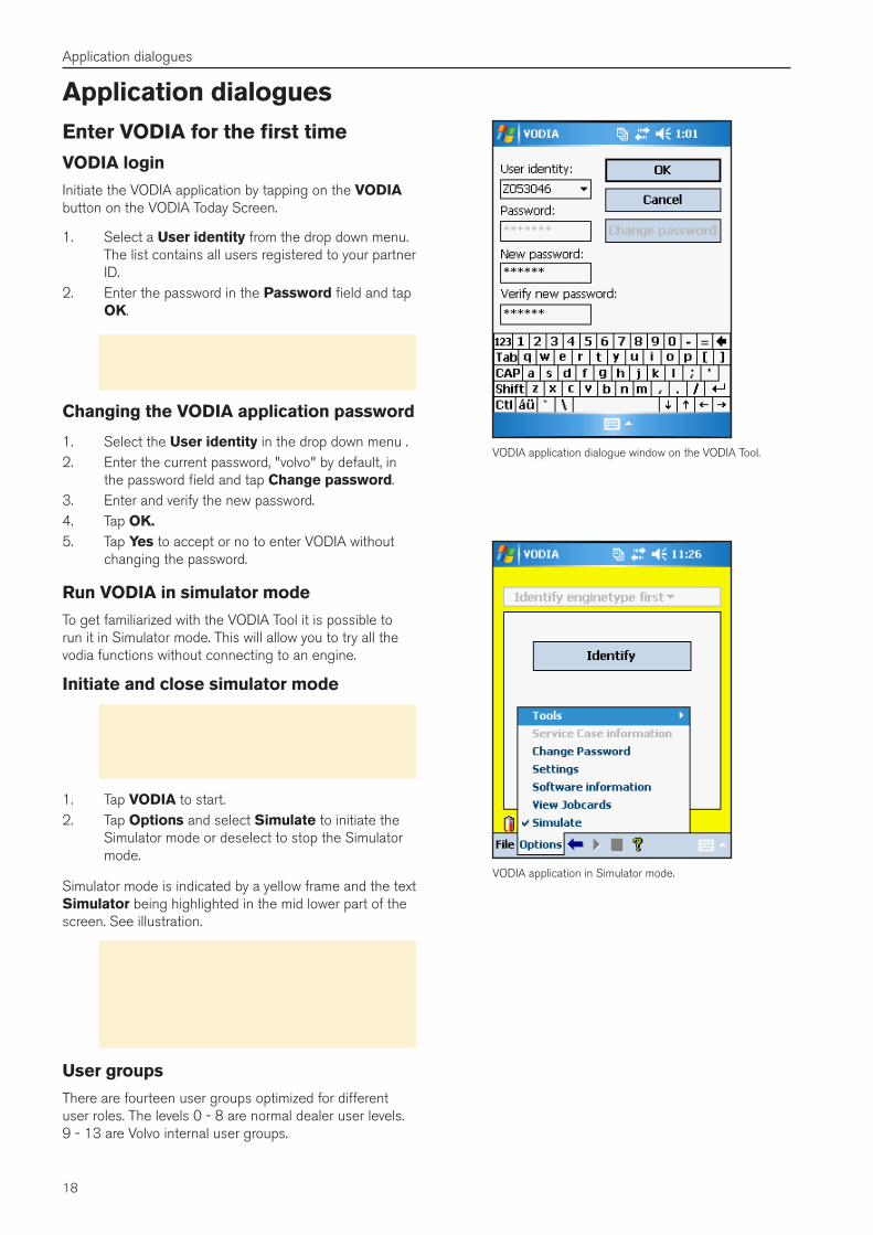
1. Make sure the log is stopped.2. Go to Options – Settings.3. Check the Enable log box.4. Type a file name in the text box.5. Tap Create File.6. Tap ok.7. Tap play to start logging.
The file is saved in the PentaNMEA folder on the SD card. The file is a text file and can be viewed in notepad.
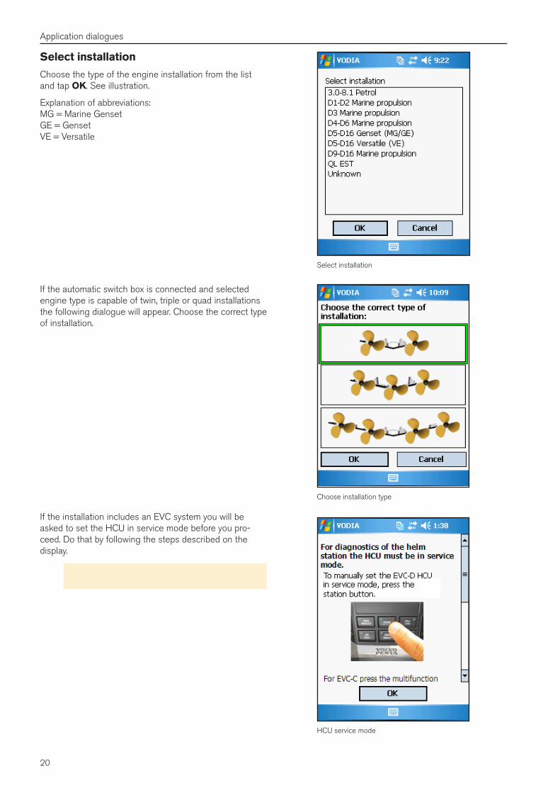
INTERFACE UPDATEThe INTERFACE UPDATE application updates the soft-ware in the communication jacket to the latest version.
This application can also be used for function check of the jacket. If the flash fails the jacket is most likely broken.
1. Make sure that the jacket is connected to an external power source, and that the blue LED on the jacket is on. Either connect to an engine with the high speed cable or using the AC adapter and D-sub/DC jacket adapter.
2. Start the INTERFACE UPDATE application.3. Tap File - Flash Interface.4. Tap on the file name to start the update.
INFOThe INFO page will present information like Partner ID, Client ID, PDA serial no, VODIA-version + build date, Da-tabase date, EGC date, PentaEDC1 version + build date, PentaEDC1 datasets date, PentaMEFI version + build date, PentaEDC4 version + build date, Hotfix version.
Penta NMEA LOG
Penta NMEA LOG
INTERFACE update
18
Application dialogues
VODIA application in Simulator mode.
Application dialoguesEnter VODIA for the first timeVODIA login
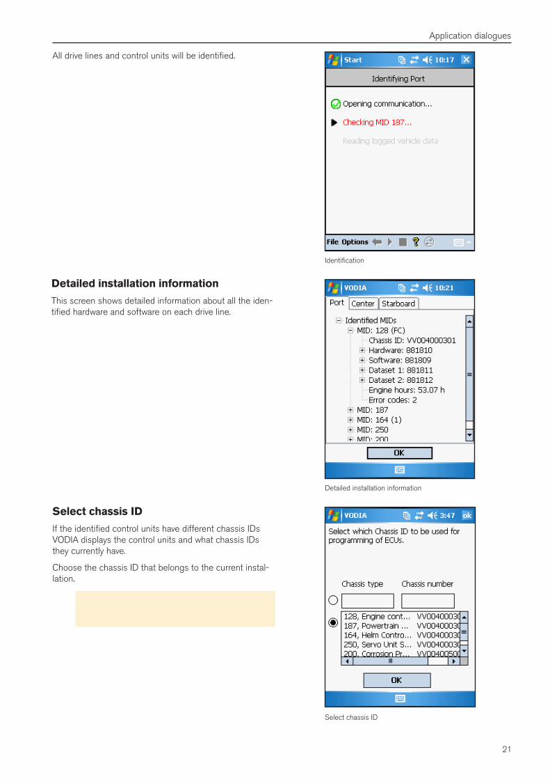
Initiate the VODIA application by tapping on the VODIA button on the VODIA Today Screen.
1. Select a User identity from the drop down menu. The list contains all users registered to your partner ID.
2. Enter the password in the Password field and tap OK.
Note! When using VODIA for the first time after downloading a user file from Volvo Penta Partner Network, the default password is volvo.
Changing the VODIA application password
1. Select the User identity in the drop down menu .2. Enter the current password, "volvo" by default, in
the password field and tap Change password.3. Enter and verify the new password.4. Tap OK�5. Tap Yes to accept or no to enter VODIA without
changing the password.
Run VODIA in simulator mode
To get familiarized with the VODIA Tool it is possible to run it in Simulator mode. This will allow you to try all the vodia functions without connecting to an engine.
Initiate and close simulator mode
Note! The respective VODIA, PentaEDC1 and PentaEDC4 applications are possible to run in simulator mode. The PentaMEFI application how-ever, does not support this function.
1. Tap VODIA to start.2. Tap Options and select Simulate to initiate the
Simulator mode or deselect to stop the Simulator mode.
Simulator mode is indicated by a yellow frame and the text Simulator being highlighted in the mid lower part of the screen. See illustration.
Note! If you can't deactivate the simulator mode you might have to update the users, if that does not help you have not got the authority level to run VODIA. If so, contact your Volvo Penta trainer who arranges Vodia classes and can authorize a higher user level.
User groups
There are fourteen user groups optimized for different user roles. The levels 0 - 8 are normal dealer user levels. 9 - 13 are Volvo internal user groups.
VODIA application dialogue window on the VODIA Tool.

19
Application dialogues
Identify
Job card
Connecting to the engineWhen identifying, VODIA collects information about the system and its control units. All information about the control units and software is saved in the job card.
1. Make sure that the Vodia Tool is connected to the engine and that the power is turned on.
2. Tap on the Identify button.
Create a new job card
A job card is a kind of receipt of every VODIA operation that is performed on an engine. A job card can be used more than once if not finalized.
Create a new job card or select an existing one in the drop down menu.
1. Tap on the empty text field.2. Activate the software keyboard and choose name
for the Job card.3. Tap OK to create the new job card.
To select an existing job card:
1. Activate the drop down menu.2. Select the preferred job card from the list.3. Tap ok to open the selected job card.
Job cards on the VODIA Web
Job cards can also be viewed and managed from the VODIA Web site, www.vppn.com. For example, parameter settings of an engine can be printed out.
1. Make sure the VODIA Tool is connected to the PC2. Go to Job card under VODIA in the menu. 3. Press View job card for a list of the job cards on
your VODIA Tool. 4. Each job card can be viewed, deleted or saved
centrally on the VODIA Web page.
Note! If a job card is saved centrally on the VODIA Web page it will automatically be erased from the VODIA Tool.
5. Under Find job card it is possible to search and view job cards saved by a specific dealer.
Note! It is recommended to report the job card centrally if it is related to warranty operations.
20
Application dialogues
Select installation
Choose the type of the engine installation from the list and tap OK. See illustration.
Explanation of abbreviations: MG = Marine Genset GE = Genset VE = Versatile
Select installation
Choose installation type
HCU service mode
If the installation includes an EVC system you will be asked to set the HCU in service mode before you pro-ceed. Do that by following the steps described on the display.
Note! You can scroll down to see the older types of EVC system.
If the automatic switch box is connected and selected engine type is capable of twin, triple or quad installations the following dialogue will appear. Choose the correct type of installation.
21
Application dialogues
Select chassis ID
Identification
Detailed installation information
Select chassis ID
If the identified control units have different chassis IDs VODIA displays the control units and what chassis IDs they currently have.
Choose the chassis ID that belongs to the current instal-lation.
Important! If choosing wrong chassis ID and reprogramming all ECUs, you won't be able to change back to the old chassis ID again.
Detailed installation information
This screen shows detailed information about all the iden-tified hardware and software on each drive line.
All drive lines and control units will be identified.
22
Application dialogues
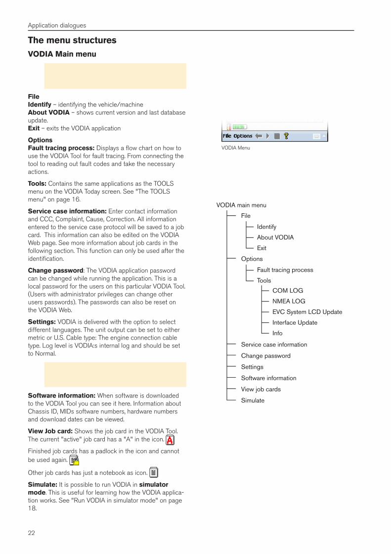
The menu structuresVODIA Main menu
Note! The buttons shown on the right illustration are only visible after you have logged in and the VODIA application has started.
File Identify – identifying the vehicle/machine About VODIA – shows current version and last database update. Exit – exits the VODIA application
Options Fault tracing process: Displays a flow chart on how to use the VODIA Tool for fault tracing. From connecting the tool to reading out fault codes and take the necessary actions.
Tools: Contains the same applications as the TOOLS menu on the VODIA Today screen. See "The TOOLS menu" on page 16.
Service case information: Enter contact information and CCC, Complaint, Cause, Correction. All information entered to the service case protocol will be saved to a job card. This information can also be edited on the VODIA Web page. See more information about job cards in the following section. This function can only be used after the identification.
Change password: The VODIA application password can be changed while running the application. This is a local password for the users on this particular VODIA Tool. (Users with administrator privileges can change other users passwords). The passwords can also be reset on the VODIA Web.
Settings: VODIA is delivered with the option to select different languages. The unit output can be set to either metric or U.S. Cable type: The engine connection cable type. Log level is VODIA:s internal log and should be set to Normal.
Note! The language data may be incorrectly dis-played if the settings are changed while connected to an engine.
Software information: When software is downloaded to the VODIA Tool you can see it here. Information about Chassis ID, MIDs software numbers, hardware numbers and download dates can be viewed.
View Job card: Shows the job card in the VODIA Tool. The current "active" job card has a "A" in the icon.
Finished job cards has a padlock in the icon and cannot be used again.
Other job cards has just a notebook as icon.
Simulate: It is possible to run VODIA in simulator mode. This is useful for learning how the VODIA applica-tion works. See "Run VODIA in simulator mode" on page 18.
VODIA Menu
23
Application dialogues
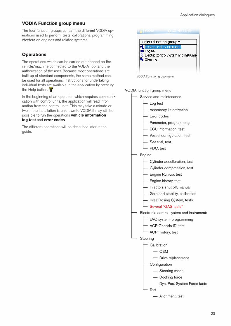
VODIA Function group menu
The four function groups contain the different VODIA op-erations used to perform tests, calibrations, programming etcetera on engines and related systems.
Operations
The operations which can be carried out depend on the vehicle/machine connected to the VODIA Tool and the authorization of the user. Because most operations are built up of standard components, the same method can be used for all operations. Instructions for undertaking individual tests are available in the application by pressing the Help button.
In the beginning of an operation which requires communi-cation with control units, the application will read infor-mation from the control units. This may take a minute or two. If the installation is unknown to VODIA it may still be possible to run the operations vehicle information log test and error codes.
The different operations will be described later in the guide.
VODIA Function group menu
24
Application dialogues
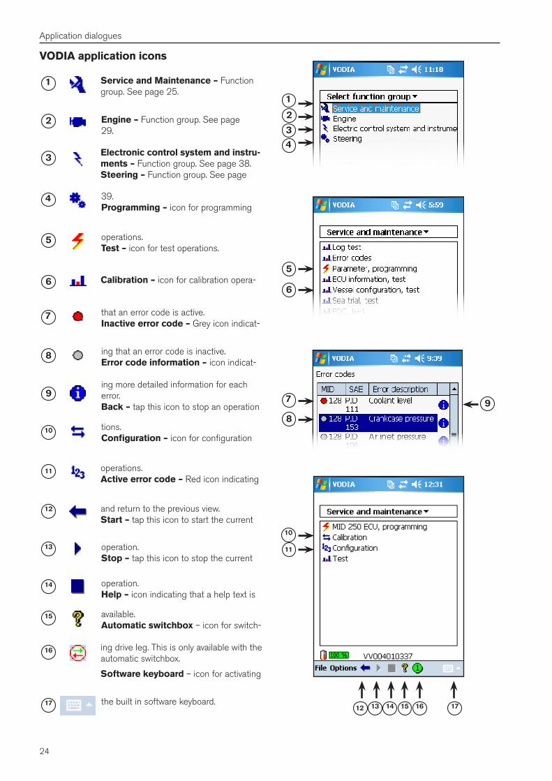
Service and Maintenance – Function group. See page 25.
15 1716
4
9
5
10
6
7
8
3
2
1
141312
11
1
14
16
17
15
4
8
5
10
9
6
7
3
2
13
12
11
VODIA application icons
Engine – Function group. See page 29.
Electronic control system and instru-ments – Function group. See page 38. Steering – Function group. See page
39. Programming – icon for programming
operations. Test – icon for test operations.
Calibration – icon for calibration opera-
tions. Configuration – icon for configuration
operations. Active error code – Red icon indicating
that an error code is active. Inactive error code – Grey icon indicat-
ing that an error code is inactive. Error code information – icon indicat-
ing more detailed information for each error. Back – tap this icon to stop an operation
and return to the previous view. Start – tap this icon to start the current
operation. Stop – tap this icon to stop the current
operation. Help – icon indicating that a help text is
available. Automatic switchbox – icon for switch-
ing drive leg. This is only available with the automatic switchbox.
Software keyboard – icon for activating
the built in software keyboard.
25
Application dialogues
Select function group
This is the VODIA "main menu". Tap on the function group name. To return to the main selection screen, tap on the selected function group name in the drop down menu above the group selections or use the back arrow.
Service and maintenance - General tests and fault tracing for the entire system.
Engine - Tests and programming related to the engine and the engine ECU.
Electric control system and instruments - Tests and programming related to the EVC system and CIU or DCU in industrial systems.
Steering - IPS and Sterndrive Joystick programming, set-tings and calibrations.
Select function group
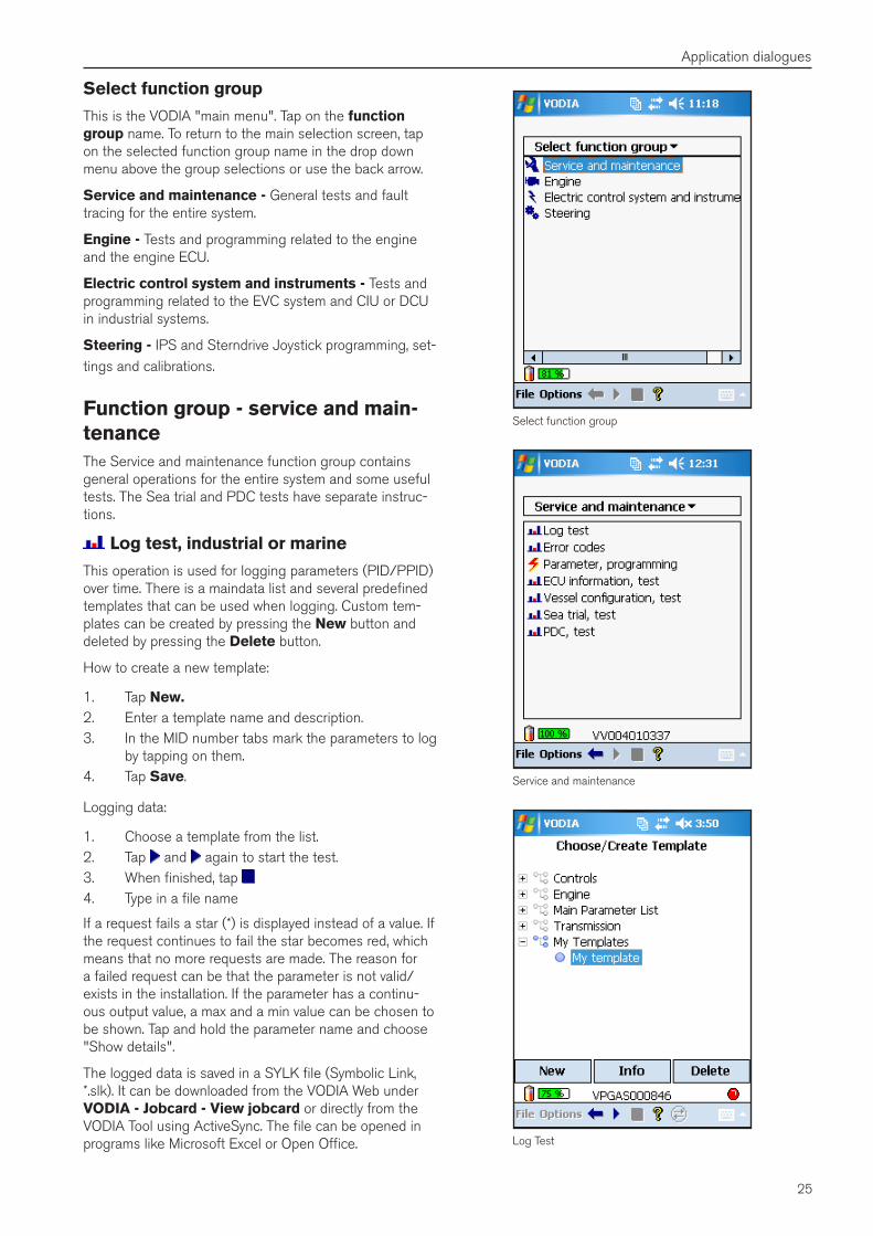
Service and maintenance
Log Test
Function group - service and main-tenanceThe Service and maintenance function group contains general operations for the entire system and some useful tests. The Sea trial and PDC tests have separate instruc-tions.
Log test, industrial or marine
This operation is used for logging parameters (PID/PPID) over time. There is a maindata list and several predefined templates that can be used when logging. Custom tem-plates can be created by pressing the New button and deleted by pressing the Delete button.
How to create a new template:
1. Tap New�2. Enter a template name and description.3. In the MID number tabs mark the parameters to log
by tapping on them.4. Tap Save.
Logging data:
1. Choose a template from the list.2. Tap and again to start the test.3. When finished, tap 4. Type in a file name
If a request fails a star (*) is displayed instead of a value. If the request continues to fail the star becomes red, which means that no more requests are made. The reason for a failed request can be that the parameter is not valid/exists in the installation. If the parameter has a continu-ous output value, a max and a min value can be chosen to be shown. Tap and hold the parameter name and choose "Show details".
The logged data is saved in a SYLK file (Symbolic Link, *.slk). It can be downloaded from the VODIA Web under VODIA - Jobcard - View jobcard or directly from the VODIA Tool using ActiveSync. The file can be opened in programs like Microsoft Excel or Open Office.
26
Application dialogues
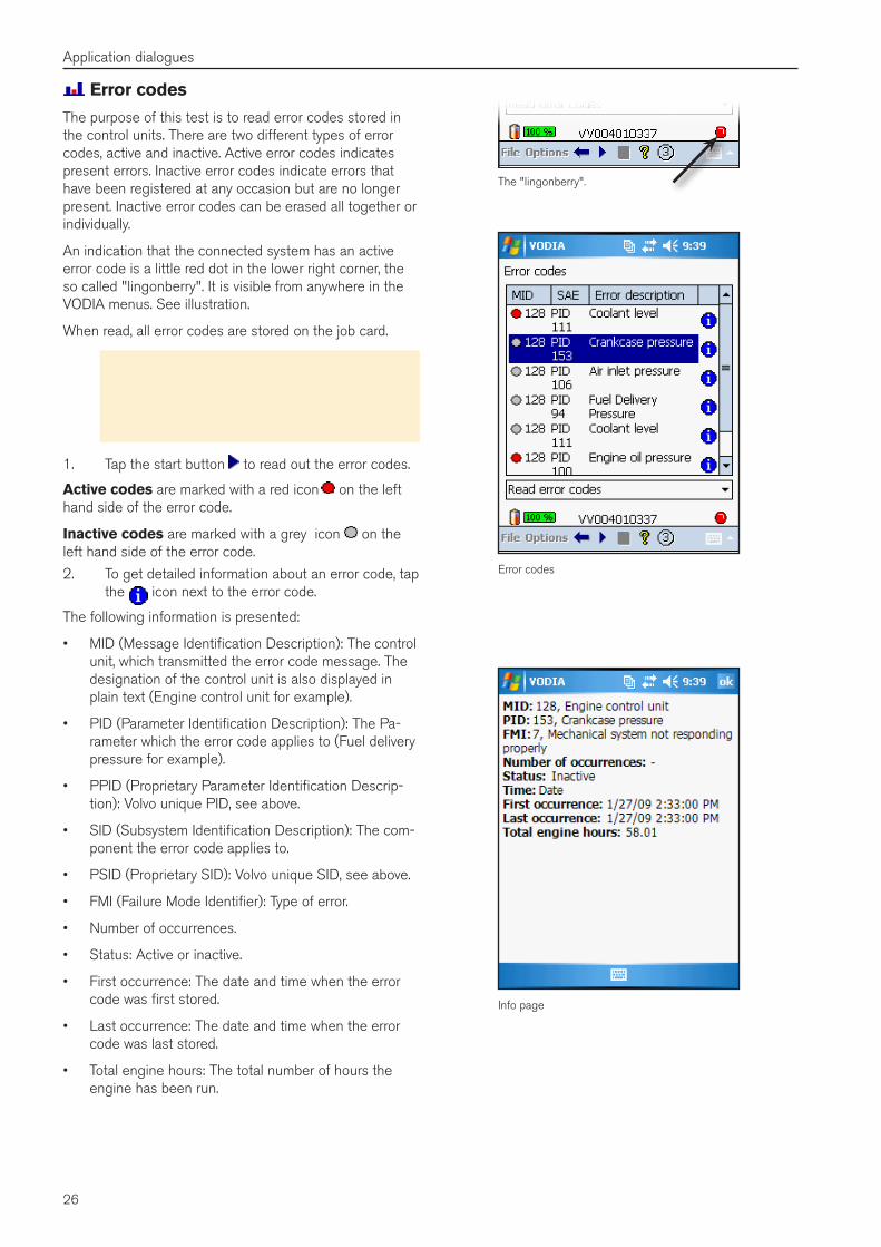
Error codes
The purpose of this test is to read error codes stored in the control units. There are two different types of error codes, active and inactive. Active error codes indicates present errors. Inactive error codes indicate errors that have been registered at any occasion but are no longer present. Inactive error codes can be erased all together or individually.
An indication that the connected system has an active error code is a little red dot in the lower right corner, the so called "lingonberry". It is visible from anywhere in the VODIA menus. See illustration.
When read, all error codes are stored on the job card.
Note! All logged error codes are erased when parameters are programmed or read when using VODIA. The error codes should be identified and then saved to a job card to ensure that the error code information will be available later on.
1. Tap the start button to read out the error codes.
Active codes are marked with a red icon on the left hand side of the error code.
Inactive codes are marked with a grey icon on the left hand side of the error code.
2. To get detailed information about an error code, tap the icon next to the error code.
The following information is presented:
• MID (Message Identification Description): The control unit, which transmitted the error code message. The designation of the control unit is also displayed in plain text (Engine control unit for example).
• PID (Parameter Identification Description): The Pa-rameter which the error code applies to (Fuel delivery pressure for example).
• PPID (Proprietary Parameter Identification Descrip-tion): Volvo unique PID, see above.
• SID (Subsystem Identification Description): The com-ponent the error code applies to.
• PSID (Proprietary SID): Volvo unique SID, see above.
• FMI (Failure Mode Identifier): Type of error.
• Number of occurrences.
• Status: Active or inactive.
• First occurrence: The date and time when the error code was first stored.
• Last occurrence: The date and time when the error code was last stored.
• Total engine hours: The total number of hours the engine has been run.
The "lingonberry".
Info page
Error codes
27
Application dialogues
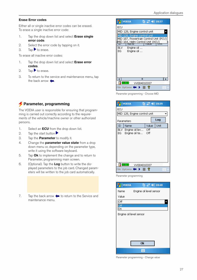
Erase Error codes
Either all or single inactive error codes can be erased. To erase a single inactive error code:
1. Tap the drop down list and select Erase single error code.
2. Select the error code by tapping on it.3. Tap to erase.
To erase all inactive error codes:
1. Tap the drop down list and select Erase error codes.
2. Tap to erase.
3. To return to the service and maintenance menu, tap the back arrow .
Parameter programming - Choose MID
Parameter programming
Parameter programming - Change value
Parameter, programming
The VODIA user is responsible for ensuring that program-ming is carried out correctly according to the require-ments of the vehicle/machine owner or other authorized persons.
1. Select an ECU from the drop down list. 2. Tap the start button 3. Tap the Parameter to modify it.4. Change the parameter value state from a drop
down menu or, depending on the parameter type, write it using the software keyboard.
5. Tap Ok to implement the change and to return to Parameter, programming main screen.
6. (Optional). Tap the Log button to write the dis-played parameters to the job card. Changed param-eters will be written to the job card automatically.
Note! The parameter programming operation may require that the main switch is turned off for ten seconds. Or, if EMS, the key is turned off. Other-wise, the engine may not start.
7. Tap the back arrow to return to the Service and maintenance menu.

28
Application dialogues
ECU information, test
This operation reads out the software information from the control units.
The information available is Chassis ID, Engine number, Hardware number, Serial number, Date of manufacture, Software (MSW, Main software), Dataset 1 (DS1), Dataset 2 (DS2) and Engine hours.
1. Choose an ECU from the drop down list.2. Tap the start button.
Vessel configuration, test
Note! This operation requires a switch box.
Vessel configuration is used to check the status on all drive lines in a boat with more than one driveline. It will read out the following information: Hull ID, total number of ECUs, indication of differences between ECUs and drive legs, some parameters and accessories, software informa-tion from the ECUs, serial numbers on drives, IPS calibra-tion settings, fault code indications on all drivelines.
1. Start by tapping the play button 2. Choose the number of drivelines.3. Choose Yes if you want information from the helm
stations.4. Follow the guide and set the HCUs in service
mode.5. Continue the wizard and switch drivelines when
asked for using the switchbox.
Use the tabs to view the different data that was read out.
Sea trial, test
The Sea trial operation is a test to measure the perfor-mance of boats with Volvo Penta engines. The test should be performed in an open test area at sea with the VODIA PDA connected to the diagnostic outlet. The test results should then be reported to the Volvo Central Systems.
It is possible to use boat templates created on the VODIA Web. See "The VODIA Web" on page 44.
Download separate Sea trial manual from the VODIA Web. See "Sea trial" on page 47.
PDC, test
The Pre Delivery Commissioning (PDC) test is used to verify Volvo Penta engine installations. The test is per-formed before or during the delivery of the boat/engine to the customer. The test shall be reported to the Volvo central system where it is possible to print a report. The report is to be given to the customer as a reference. It is recommended that the PDC report is kept together with the driver manual or Warranty and Service book.
The Sea trial boat templates can also be used in the PDC operation.
For more info refer to the Warranty and Service book.
ECU information, test
Vessel configuration, test
PDC, test
29
Application dialogues
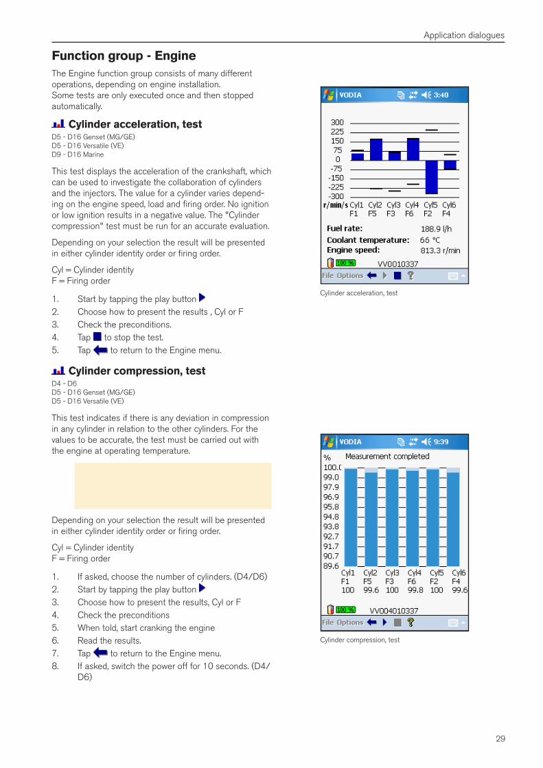
Function group - EngineThe Engine function group consists of many different operations, depending on engine installation. Some tests are only executed once and then stopped automatically.
Cylinder acceleration, testD5 - D16 Genset (MG/GE) D5 - D16 Versatile (VE) D9 - D16 Marine
This test displays the acceleration of the crankshaft, which can be used to investigate the collaboration of cylinders and the injectors. The value for a cylinder varies depend-ing on the engine speed, load and firing order. No ignition or low ignition results in a negative value. The "Cylinder compression" test must be run for an accurate evaluation.
Depending on your selection the result will be presented in either cylinder identity order or firing order.
Cyl = Cylinder identity F = Firing order
1. Start by tapping the play button 2. Choose how to present the results , Cyl or F3. Check the preconditions.4. Tap to stop the test.5. Tap to return to the Engine menu.
Cylinder compression, testD4 - D6 D5 - D16 Genset (MG/GE) D5 - D16 Versatile (VE)
This test indicates if there is any deviation in compression in any cylinder in relation to the other cylinders. For the values to be accurate, the test must be carried out with the engine at operating temperature.
Note! When the test and evaluation are complet-ed, the ignition key must be turned to 0 and then back to the driving position to start a new test or to restart the engine.
Depending on your selection the result will be presented in either cylinder identity order or firing order.
Cyl = Cylinder identity F = Firing order
1. If asked, choose the number of cylinders. (D4/D6)2. Start by tapping the play button 3. Choose how to present the results, Cyl or F4. Check the preconditions5. When told, start cranking the engine6. Read the results.7. Tap to return to the Engine menu.8. If asked, switch the power off for 10 seconds. (D4/
D6)
Cylinder acceleration, test
Cylinder compression, test
30
Application dialogues
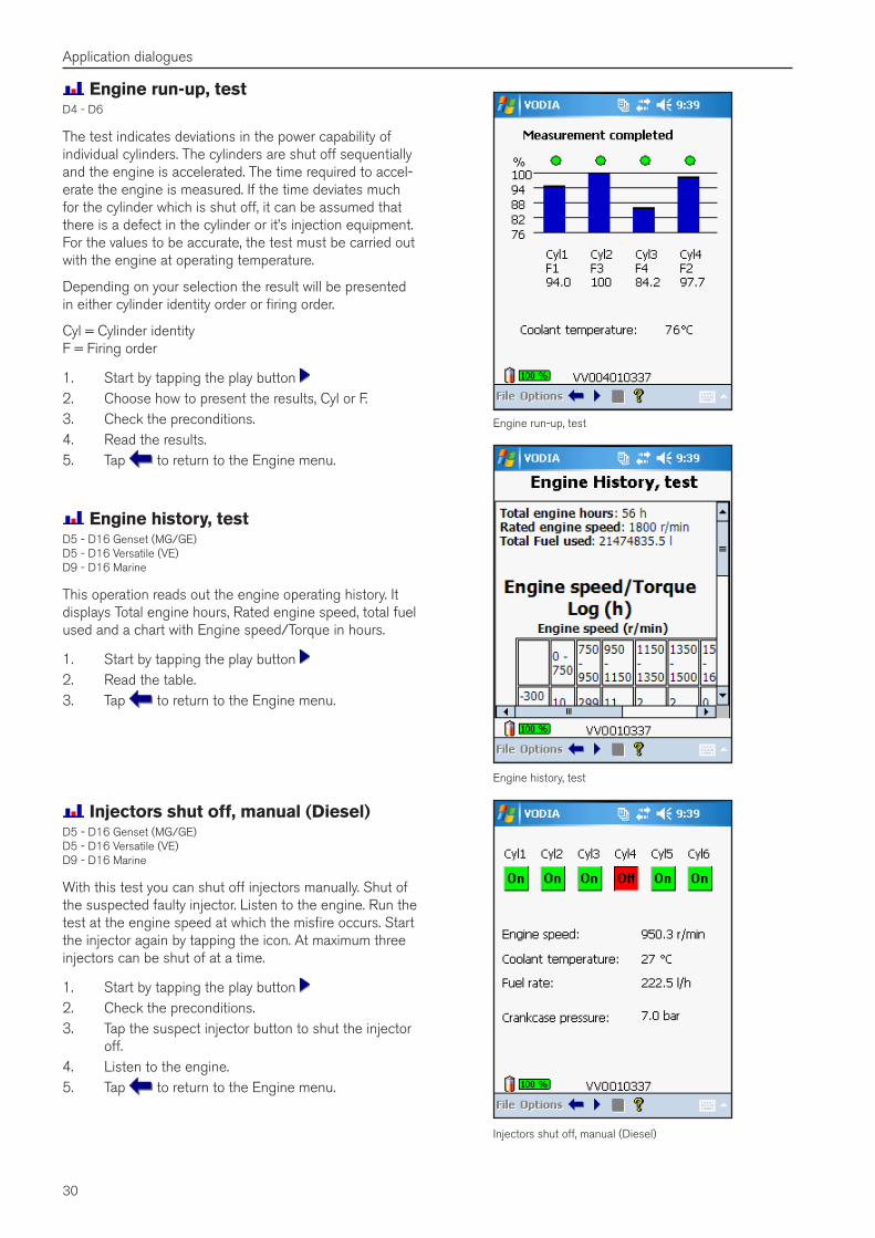
Engine run-up, testD4 - D6
The test indicates deviations in the power capability of individual cylinders. The cylinders are shut off sequentially and the engine is accelerated. The time required to accel-erate the engine is measured. If the time deviates much for the cylinder which is shut off, it can be assumed that there is a defect in the cylinder or it’s injection equipment. For the values to be accurate, the test must be carried out with the engine at operating temperature.
Depending on your selection the result will be presented in either cylinder identity order or firing order.
Cyl = Cylinder identity F = Firing order
1. Start by tapping the play button 2. Choose how to present the results, Cyl or F.3. Check the preconditions.4. Read the results.5. Tap to return to the Engine menu.
Engine run-up, test
Engine history, test
Injectors shut off, manual (Diesel)
Engine history, testD5 - D16 Genset (MG/GE) D5 - D16 Versatile (VE) D9 - D16 Marine
This operation reads out the engine operating history. It displays Total engine hours, Rated engine speed, total fuel used and a chart with Engine speed/Torque in hours.
1. Start by tapping the play button 2. Read the table.3. Tap to return to the Engine menu.
Injectors shut off, manual (Diesel)D5 - D16 Genset (MG/GE) D5 - D16 Versatile (VE) D9 - D16 Marine
With this test you can shut off injectors manually. Shut of the suspected faulty injector. Listen to the engine. Run the test at the engine speed at which the misfire occurs. Start the injector again by tapping the icon. At maximum three injectors can be shut of at a time.
1. Start by tapping the play button 2. Check the preconditions.3. Tap the suspect injector button to shut the injector
off.4. Listen to the engine.5. Tap to return to the Engine menu.
31
Application dialogues
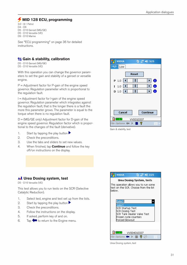
Gain & stability, test
MID 128 ECU, programming3.0 - 8.1 Petrol D4 - D6 D5 - D16 Genset (MG/GE) D5 - D16 Versatile (VE) D9 - D16 Marine
See "ECU programming" on page 36 for detailed instructions.
Gain & stability, calibrationD5 - D16 Genset (MG/GE) D5 - D16 Versatile (VE)
With this operation you can change the governor param-eters to set the gain and stability of a genset or versatile engine.
P = Adjustment factor for P-gain of the engine speed governor. Regulation parameter which is proportional to the regulation fault.
I = Adjustment factor for I-gain of the engine speed governor. Regulation parameter which integrates against the regulation fault, that is the longer there is a fault the more this parameter grows. The parameter is equal to the torque when there is no regulation fault.
D = (MG/GE only) Adjustment factor for D-gain of the engine speed governor. Regulation factor which is propor-tional to the changes of the fault (derivative).
1. Start by tapping the play button 2. Check the preconditions.3. Use the tabs and sliders to set new values.4. When finished, tap Continue and follow the key
off/on instructions on the display.
Note! More information about this operation and detailed instructions are available in service bulletin 36–6 006.
Urea Dosing system, test
Urea Dosing system, testD5 - D16 Versatile (VE)
This test allows you to run tests on the SCR (Selective Catalytic Reduction).
1. Select test, engine and test set up from the lists.2. Start by tapping the play button 3. Check the preconditions.4. Follow the instructions on the display.5. If asked, perform key of and on.6. Tap to return to the Engine menu.
32
Application dialogues
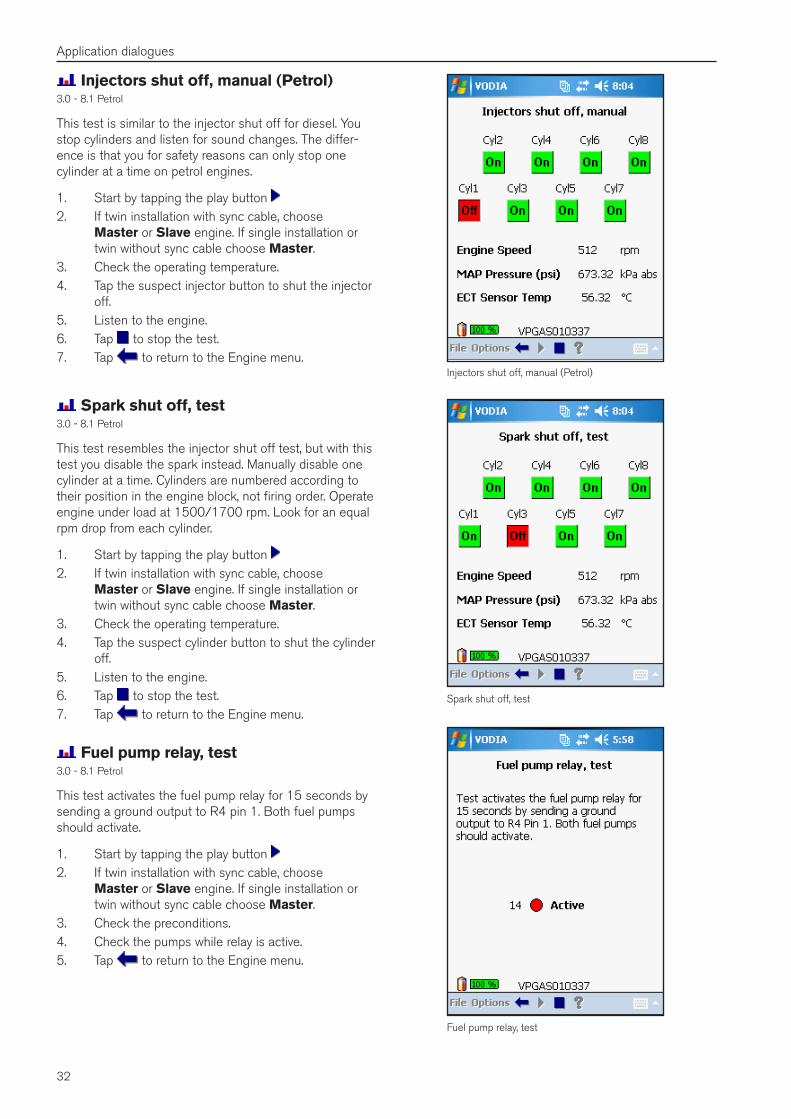
Spark shut off, test3.0 - 8.1 Petrol
This test resembles the injector shut off test, but with this test you disable the spark instead. Manually disable one cylinder at a time. Cylinders are numbered according to their position in the engine block, not firing order. Operate engine under load at 1500/1700 rpm. Look for an equal rpm drop from each cylinder.
1. Start by tapping the play button 2. If twin installation with sync cable, choose
Master or Slave engine. If single installation or twin without sync cable choose Master.
3. Check the operating temperature.4. Tap the suspect cylinder button to shut the cylinder
off.5. Listen to the engine. 6. Tap to stop the test.7. Tap to return to the Engine menu.
Spark shut off, test
Fuel pump relay, test
Fuel pump relay, test3.0 - 8.1 Petrol
This test activates the fuel pump relay for 15 seconds by sending a ground output to R4 pin 1. Both fuel pumps should activate.
1. Start by tapping the play button 2. If twin installation with sync cable, choose
Master or Slave engine. If single installation or twin without sync cable choose Master.
3. Check the preconditions.4. Check the pumps while relay is active.5. Tap to return to the Engine menu.
Injectors shut off, manual (Petrol)
Injectors shut off, manual (Petrol)3.0 - 8.1 Petrol
This test is similar to the injector shut off for diesel. You stop cylinders and listen for sound changes. The differ-ence is that you for safety reasons can only stop one cylinder at a time on petrol engines.
1. Start by tapping the play button 2. If twin installation with sync cable, choose
Master or Slave engine. If single installation or twin without sync cable choose Master.
3. Check the operating temperature.4. Tap the suspect injector button to shut the injector
off.5. Listen to the engine.6. Tap to stop the test.7. Tap to return to the Engine menu.
33
Application dialogues
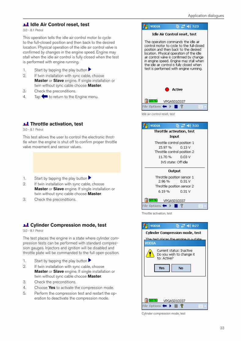
Idle air control reset, test
Idle Air Control reset, test3.0 - 8.1 Petrol
This operation tells the idle air control motor to cycle to the full-closed position and then back to the desired location. Physical operation of the idle air control valve is confirmed by changes in the engine speed. Engine may stall when the idle air control is fully closed when the test is performed with engine running.
1. Start by tapping the play button 2. If twin installation with sync cable, choose
Master or Slave engine. If single installation or twin without sync cable choose Master.
3. Check the preconditions.4. Tap to return to the Engine menu.
Throttle activation, test3.0 - 8.1 Petrol
This test allows the user to control the electronic throt-tle when the engine is shut off to confirm proper throttle valve movement and sensor values.
Warning! The throttle valve motor is very powerful and can cause personal injury. Do not touch the throttle plate at any time! Be certain that the flame arrestor is reinstalled immediately after testing.
1. Start by tapping the play button 2. If twin installation with sync cable, choose
Master or Slave engine. If single installation or twin without sync cable choose Master.
3. Check the preconditions.
Throttle activation, test
Cylinder compression mode, test
Cylinder Compression mode, test3.0 - 8.1 Petrol
The test places the engine in a state where cylinder com-pression tests can be performed with standard compres-sion gauges. Injectors and ignition will be disabled and throttle plate will be commanded to the full open position.
1. Start by tapping the play button 2. If twin installation with sync cable, choose
Master or Slave engine. If single installation or twin without sync cable choose Master.
3. Check the preconditions.4. Choose Yes to activate the compression mode.5. Perform the compression test and restart the op-
eration to deactivate the compression mode.
34
Application dialogues
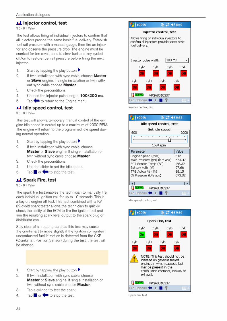
Idle speed control, test3.0 - 8.1 Petrol
This test will allow a temporary manual control of the en-gine idle speed in neutral up to a maximum of 2000 RPM. The engine will return to the programmed idle speed dur-ing normal operation.
1. Start by tapping the play button 2. If twin installation with sync cable, choose
Master or Slave engine. If single installation or twin without sync cable choose Master.
3. Check the preconditions.4. Use the slider to set the idle speed.5. Tap or to stop the test.
Idle speed control, test
Spark fire, test
Spark Fire, test3.0 - 8.1 Petrol
The spark fire test enables the technician to manually fire each individual ignition coil for up to 10 seconds. This is a key on, engine off test. This test combined with a KV (Kilovolt) spark tester allows the technician to quickly check the ability of the ECM to fire the ignition coil and see the resulting spark level output to the spark plug or distributor cap.
Stay clear of all rotating parts as this test may cause the crankshaft to move slightly if the ignition coil ignites uncombusted fuel. If motion is detected from the CKP (Crankshaft Position Sensor) during the test, the test will be aborted.
Warning! This test should not be initiated on en-gines in which gaseous fuel may be present in the combustion chamber, intake or exhaust.
1. Start by tapping the play button 2. If twin installation with sync cable, choose
Master or Slave engine. If single installation or twin without sync cable choose Master.
3. Tap a cylinder to test the spark.4. Tap or to stop the test.
Injector control, test
Injector control, test3.0 - 8.1 Petrol
The test allows firing of individual injectors to confirm that all injectors provide the same basic fuel delivery. Establish fuel rail pressure with a manual gauge, then fire an injec-tor and observe the pressure drop. The engine must be cranked for ten revolutions to clear fuel, and key cycled off/on to restore fuel rail pressure before firing the next injector.
1. Start by tapping the play button 2. If twin installation with sync cable, choose Master
or Slave engine. If single installation or twin with-out sync cable choose Master.
3. Check the preconditions.4. Choose the injector pulse length. 100/200 ms.5. Tap to return to the Engine menu.
35
Application dialogues
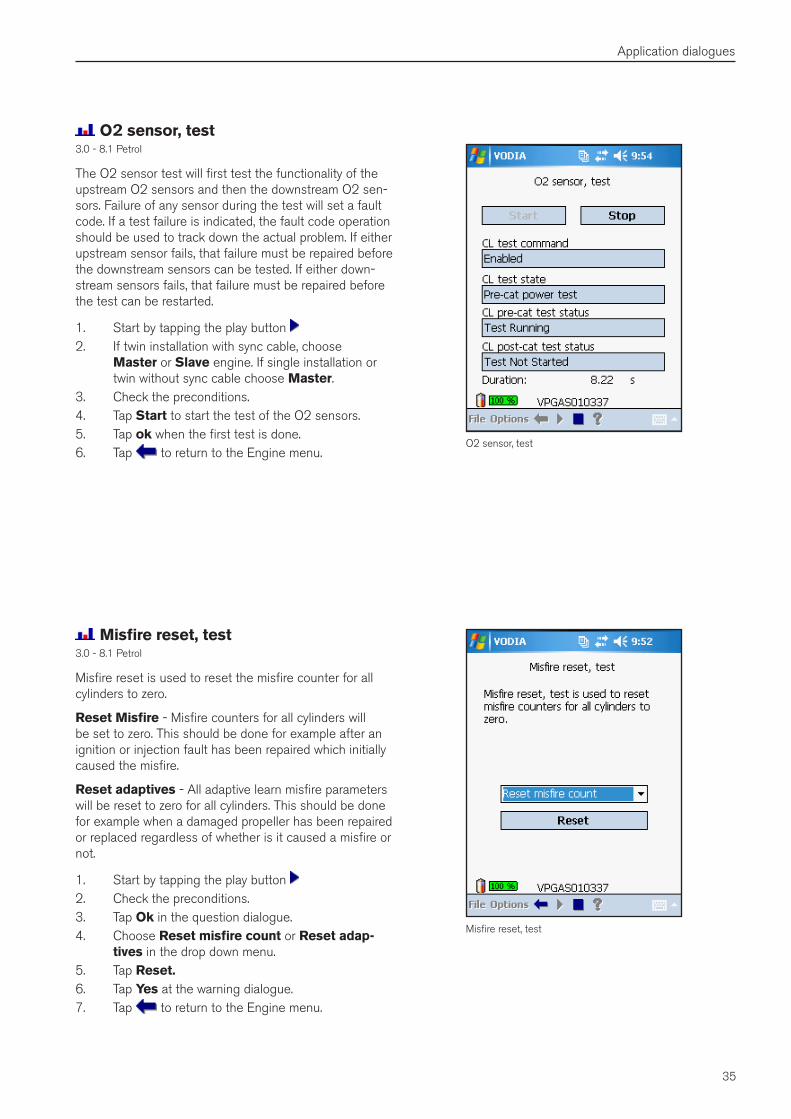
O2 sensor, test3.0 - 8.1 Petrol
The O2 sensor test will first test the functionality of the upstream O2 sensors and then the downstream O2 sen-sors. Failure of any sensor during the test will set a fault code. If a test failure is indicated, the fault code operation should be used to track down the actual problem. If either upstream sensor fails, that failure must be repaired before the downstream sensors can be tested. If either down-stream sensors fails, that failure must be repaired before the test can be restarted.
1. Start by tapping the play button 2. If twin installation with sync cable, choose
Master or Slave engine. If single installation or twin without sync cable choose Master.
3. Check the preconditions.4. Tap Start to start the test of the O2 sensors.5. Tap ok when the first test is done.6. Tap to return to the Engine menu.
O2 sensor, test
Misfire reset, test
Misfire reset, test3.0 - 8.1 Petrol
Misfire reset is used to reset the misfire counter for all cylinders to zero.
Reset Misfire - Misfire counters for all cylinders will be set to zero. This should be done for example after an ignition or injection fault has been repaired which initially caused the misfire.
Reset adaptives - All adaptive learn misfire parameters will be reset to zero for all cylinders. This should be done for example when a damaged propeller has been repaired or replaced regardless of whether is it caused a misfire or not.
1. Start by tapping the play button 2. Check the preconditions.3. Tap Ok in the question dialogue.4. Choose Reset misfire count or Reset adap-
tives in the drop down menu.5. Tap Reset�6. Tap Yes at the warning dialogue.7. Tap to return to the Engine menu.
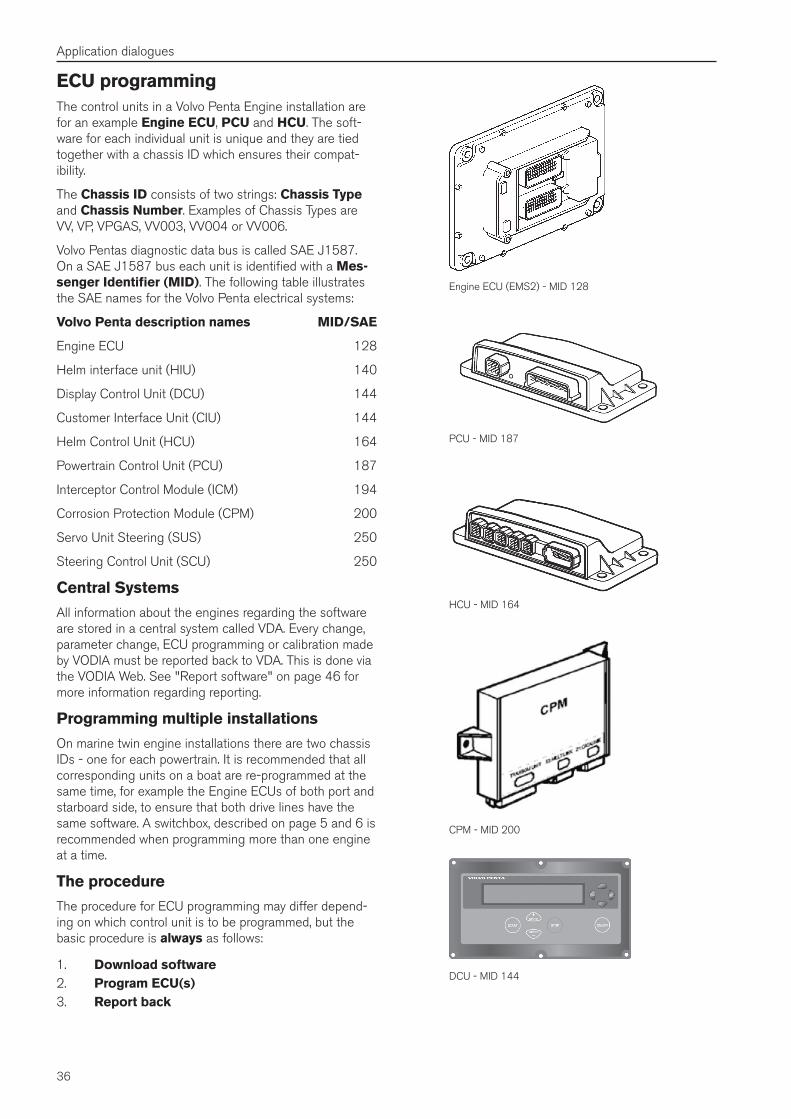
36
Application dialogues
ECU programmingThe control units in a Volvo Penta Engine installation are for an example Engine ECU, PCU and HCU. The soft-ware for each individual unit is unique and they are tied together with a chassis ID which ensures their compat-ibility.
The Chassis ID consists of two strings: Chassis Type and Chassis Number. Examples of Chassis Types are VV, VP, VPGAS, VV003, VV004 or VV006.
Volvo Pentas diagnostic data bus is called SAE J1587. On a SAE J1587 bus each unit is identified with a Mes-senger Identifier (MID). The following table illustrates the SAE names for the Volvo Penta electrical systems:
Volvo Penta description names MID/SAE
Engine ECU 128
Helm interface unit (HIU) 140
Display Control Unit (DCU) 144
Customer Interface Unit (CIU) 144
Helm Control Unit (HCU) 164
Powertrain Control Unit (PCU) 187
Interceptor Control Module (ICM) 194
Corrosion Protection Module (CPM) 200
Servo Unit Steering (SUS) 250
Steering Control Unit (SCU) 250
Central Systems
All information about the engines regarding the software are stored in a central system called VDA. Every change, parameter change, ECU programming or calibration made by VODIA must be reported back to VDA. This is done via the VODIA Web. See "Report software" on page 46 for more information regarding reporting.
Programming multiple installations
On marine twin engine installations there are two chassis IDs - one for each powertrain. It is recommended that all corresponding units on a boat are re-programmed at the same time, for example the Engine ECUs of both port and starboard side, to ensure that both drive lines have the same software. A switchbox, described on page 5 and 6 is recommended when programming more than one engine at a time.
The procedure
The procedure for ECU programming may differ depend-ing on which control unit is to be programmed, but the basic procedure is always as follows:
1. Download software2. Program ECU(s)3. Report back
Engine ECU (EMS2) - MID 128
HCU - MID 164
PCU - MID 187
CPM - MID 200
DCU - MID 144
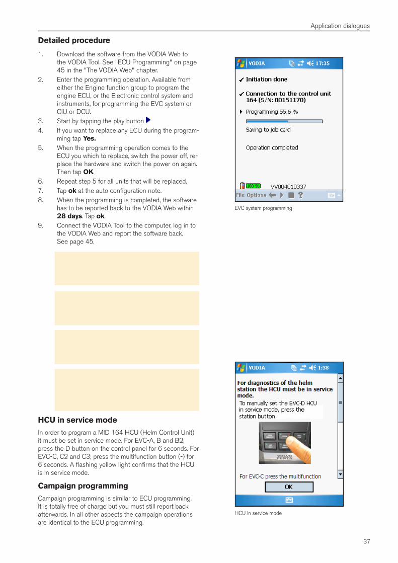
37
Application dialogues
Detailed procedure
1. Download the software from the VODIA Web to the VODIA Tool. See "ECU Programming" on page 45 in the "The VODIA Web" chapter.
2. Enter the programming operation. Available from either the Engine function group to program the engine ECU, or the Electronic control system and instruments, for programming the EVC system or CIU or DCU.
3. Start by tapping the play button 4. If you want to replace any ECU during the program-
ming tap Yes�5. When the programming operation comes to the
ECU you which to replace, switch the power off, re-place the hardware and switch the power on again. Then tap OK.
6. Repeat step 5 for all units that will be replaced.7. Tap ok at the auto configuration note.8. When the programming is completed, the software
has to be reported back to the VODIA Web within 28 days. Tap ok.
9. Connect the VODIA Tool to the computer, log in to the VODIA Web and report the software back. See page 45.
Important! If the downloaded software is not reported back after 28 days an invoice will be automatically generated. See "Invoices" on page 46.
Important! When the VODIA dialogue informs about switching the power off it is vital that the main power is switched off for ten seconds. It is strictly forbidden to just unplug the Vodia�
Important! The VODIA user is responsible for ensuring that programming is carried out correctly according to the requirements of the boat/machine owner or other authorized persons.
Warning! Under no circumstances may control units be switched between vehicles/machines for error tracing or repairs without reprogramming them. Incorrect control unit settings can result in personal injury or damage to the boat/machine.
HCU in service mode
In order to program a MID 164 HCU (Helm Control Unit) it must be set in service mode. For EVC-A, B and B2; press the D button on the control panel for 6 seconds. For EVC-C, C2 and C3; press the multifunction button (-) for 6 seconds. A flashing yellow light confirms that the HCU is in service mode.
Campaign programming
Campaign programming is similar to ECU programming. It is totally free of charge but you must still report back afterwards. In all other aspects the campaign operations are identical to the ECU programming.
HCU in service mode
EVC system programming
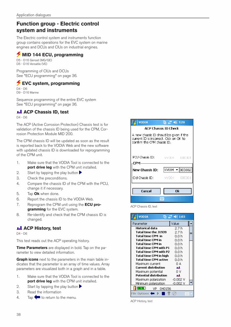
38
Application dialogues
Function group - Electric control system and instrumentsThe Electric control system and instruments function group contains operations for the EVC system on marine engines and DCUs and CIUs on industrial engines.
MID 144 ECU, programmingD5 - D16 Genset (MG/GE) D5 - D16 Versatile (VE)
Programming of CIUs and DCUs See "ECU programming" on page 36.
EVC system, programmingD4 - D6 D9 - D16 Marine
Sequence programming of the entire EVC system See "ECU programming" on page 36.
ACP Chassis ID, testD4 - D6
The ACP (Active Corrosion Protection) Chassis test is for validation of the chassis ID being used for the CPM, Cor-rosion Protection Module MID 200.
The CPM chassis ID will be updated as soon as the result is reported back to the VODIA Web and the new software with updated chassis ID is downloaded for reprogramming of the CPM unit.
1. Make sure that the VODIA Tool is connected to the port drive leg with the CPM unit installed.
2. Start by tapping the play button 3. Check the preconditions.4. Compare the chassis ID of the CPM with the PCU,
change it if necessary.5. Tap Ok when done.6. Report the chassis ID to the VODIA Web.7. Reprogram the CPM unit using the ECU pro-
gramming for the EVC system.8. Re-identify and check that the CPM chassis ID is
changed.
ACP History, testD4 - D6
This test reads out the ACP operating history.
Time Parameters are displayed in bold. Tap on the pa-rameter to view detailed information.
Graph icons next to the parameters in the main table in-dicates that the parameter is an array of time values. Array parameters are visualized both in a graph and in a table.
1. Make sure that the VODIA Tool is connected to the port drive leg with the CPM unit installed.
2. Start by tapping the play button 3. Read the information4. Tap to return to the menu.
ACP Chassis ID, test
ACP History, test

39
Application dialogues
Switch drive leg
Function group - SteeringThe Steering function group is only available when a SUS or SCU, MID 250 has been identified. That means it is only available on IPS boats and Sterndrive installations with electronic steering.
In contrast to the other function groups, Steering has three sub groups, Configuration, Calibration and Test. See "The menu structures" on page 22.
The available operations will vary depending on installation and which VODIA level you have.
Note! The Steering operations described in this guide require the automatic switchbox art. no. 21287382. You can still use the old Steering op-erations in classic mode with the old switch boxes.
Important! All calibrations and configurations must be reported back to the VODIA Web.
Switching drive leg with the Automatic switchbox
When not in an operation you can switch between the drive legs manually. The icon indicates the current con-nected drive leg.
1. Tap the Automatic switchbox icon 2. Choose installation type (Only needed once)3. Select a drive leg.4. Tap OK
Rotate drive anticlockwise
Red drive - Active/moving drive, selected for calibration.
Green drive - Calibrated/finished drive, not selected.
Rotate drive clockwise
Brown drive - Not calibrated yet, not selected.
Bracket - Use drive centre posi-tion tool between these drives
Grey arrow, inactive button - not selectable drive
Red arrow, inactive button - selected/moving drive
Red arrow, active button - moving drive, tap to confirm
Blue arrow, active button - tap to select drive
Explanation of buttons and illustrations
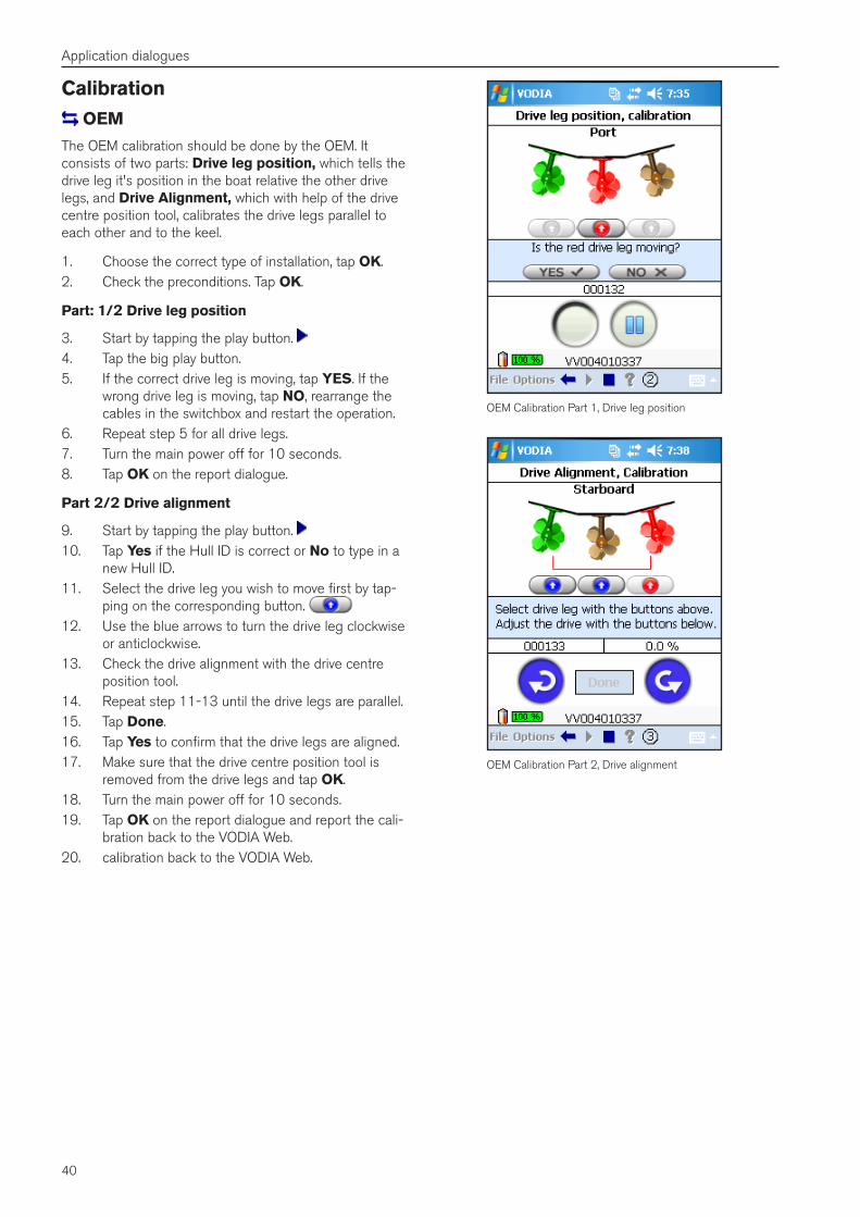
40
Application dialogues
OEM Calibration Part 1, Drive leg position
OEM Calibration Part 2, Drive alignment
Calibration OEM
The OEM calibration should be done by the OEM. It consists of two parts: Drive leg position, which tells the drive leg it's position in the boat relative the other drive legs, and Drive Alignment, which with help of the drive centre position tool, calibrates the drive legs parallel to each other and to the keel.
1. Choose the correct type of installation, tap OK.2. Check the preconditions. Tap OK.
Part: 1/2 Drive leg position
3. Start by tapping the play button. 4. Tap the big play button.5. If the correct drive leg is moving, tap YES. If the
wrong drive leg is moving, tap NO, rearrange the cables in the switchbox and restart the operation.
6. Repeat step 5 for all drive legs.7. Turn the main power off for 10 seconds.8. Tap OK on the report dialogue.
Part 2/2 Drive alignment
9. Start by tapping the play button. 10. Tap Yes if the Hull ID is correct or No to type in a
new Hull ID.11. Select the drive leg you wish to move first by tap-
ping on the corresponding button. 12. Use the blue arrows to turn the drive leg clockwise
or anticlockwise.13. Check the drive alignment with the drive centre
position tool.14. Repeat step 11-13 until the drive legs are parallel.15. Tap Done.16. Tap Yes to confirm that the drive legs are aligned.17. Make sure that the drive centre position tool is
removed from the drive legs and tap OK.18. Turn the main power off for 10 seconds.19. Tap OK on the report dialogue and report the cali-
bration back to the VODIA Web.20. calibration back to the VODIA Web.
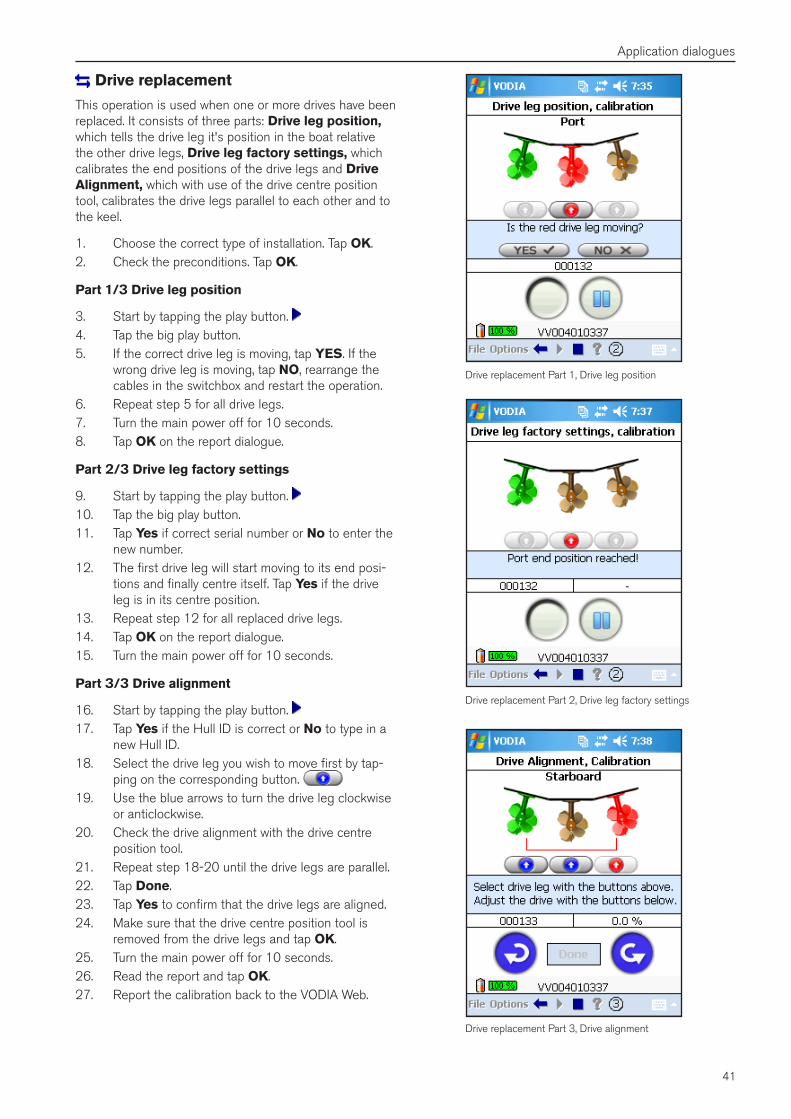
41
Application dialogues
Drive replacement
This operation is used when one or more drives have been replaced. It consists of three parts: Drive leg position, which tells the drive leg it's position in the boat relative the other drive legs, Drive leg factory settings, which calibrates the end positions of the drive legs and Drive Alignment, which with use of the drive centre position tool, calibrates the drive legs parallel to each other and to the keel.
1. Choose the correct type of installation. Tap OK.2. Check the preconditions. Tap OK.
Part 1/3 Drive leg position
3. Start by tapping the play button. 4. Tap the big play button.5. If the correct drive leg is moving, tap YES. If the
wrong drive leg is moving, tap NO, rearrange the cables in the switchbox and restart the operation.
6. Repeat step 5 for all drive legs.7. Turn the main power off for 10 seconds.8. Tap OK on the report dialogue.
Part 2/3 Drive leg factory settings
9. Start by tapping the play button. 10. Tap the big play button.11. Tap Yes if correct serial number or No to enter the
new number.12. The first drive leg will start moving to its end posi-
tions and finally centre itself. Tap Yes if the drive leg is in its centre position.
13. Repeat step 12 for all replaced drive legs.14. Tap OK on the report dialogue.15. Turn the main power off for 10 seconds.
Part 3/3 Drive alignment
16. Start by tapping the play button. 17. Tap Yes if the Hull ID is correct or No to type in a
new Hull ID.18. Select the drive leg you wish to move first by tap-
ping on the corresponding button. 19. Use the blue arrows to turn the drive leg clockwise
or anticlockwise.20. Check the drive alignment with the drive centre
position tool.21. Repeat step 18-20 until the drive legs are parallel.22. Tap Done.23. Tap Yes to confirm that the drive legs are aligned.24. Make sure that the drive centre position tool is
removed from the drive legs and tap OK.25. Turn the main power off for 10 seconds.26. Read the report and tap OK.27. Report the calibration back to the VODIA Web.
Drive replacement Part 1, Drive leg position
Drive replacement Part 2, Drive leg factory settings
Drive replacement Part 3, Drive alignment
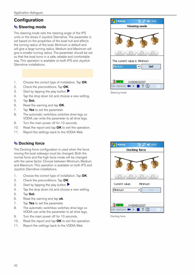
42
Application dialogues
Configuration Steering mode
The steering mode sets the steering angle of the IPS units or the drives if Joystick Sterndrive. The parameter is set based on the properties of the boat hull and affects the turning radius of the boat. Minimum is default and will give a large turning radius. Medium and Maximum will give a smaller turning radius. The parameter should be set so that the boat turns in a safe, reliable and comfortable way. This operation is available on both IPS and Joystick Sterndrive installations.
Note! It is the boat builders responsibility to set the steering mode correctly.
1. Choose the correct type of installation. Tap OK.2. Check the preconditions. Tap OK.3. Start by tapping the play button. 4. Tap the drop down list and choose a new setting.5. Tap Set�6. Read the warning and tap OK.7. Tap Yes to set the parameter.8. The automatic switchbox switches drive legs so
VODIA can write the parameter to all drive legs.9. Turn the main power off for 10 seconds. 10. Read the report and tap OK to exit the operation.11. Report the settings back to the VODIA Web.
Steering mode
Docking force
Docking force
The Docking force configuration is used when the force moving the boat sideways must be changed. Both the normal force and the high force mode will be changed with the same factor. Choose between Minimum, Medium and Maximum. This operation is available on both IPS and Joystick Sterndrive installations.
1. Choose the correct type of installation. Tap OK.2. Check the preconditions. Tap OK.3. Start by tapping the play button. 4. Tap the drop down list and choose a new setting.5. Tap Set�6. Read the warning and tap ok.7. Tap Yes to set the parameter.8. The automatic switchbox switches drive legs so
VODIA can write the parameter to all drive legs.9. Turn the main power off for 10 seconds. 10. Read the report and tap OK to exit the operation.11. Report the settings back to the VODIA Web.
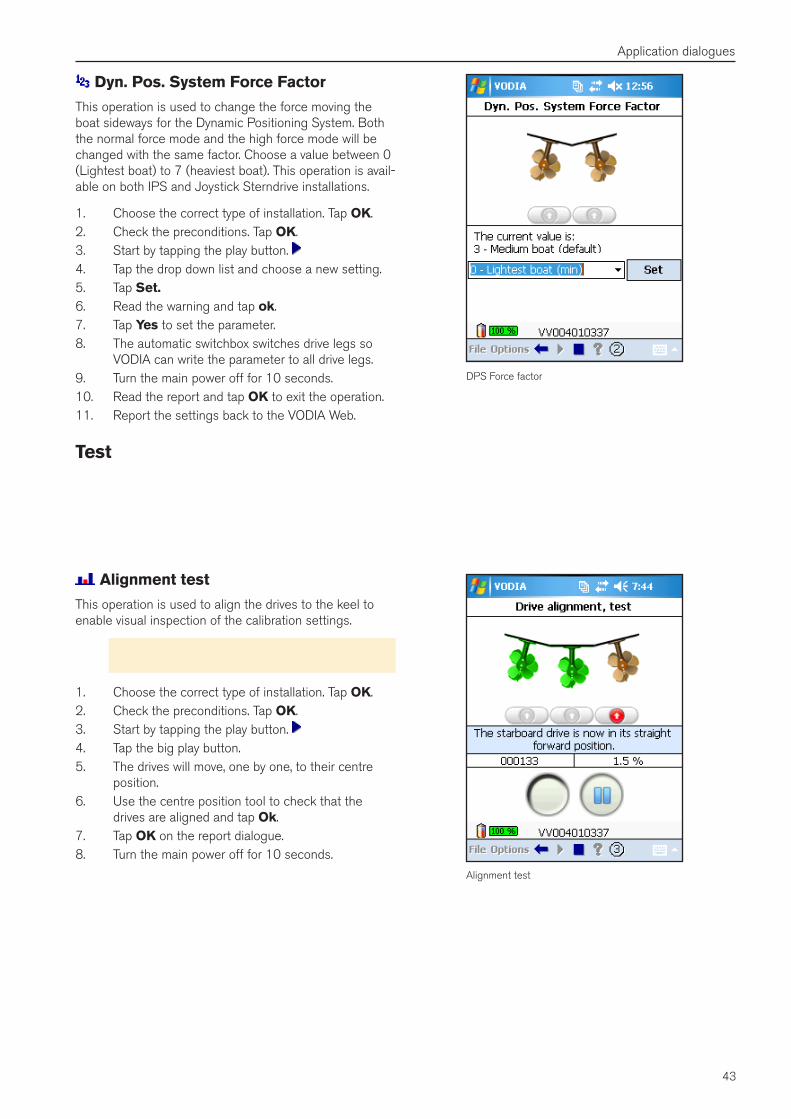
43
Application dialogues
Dyn� Pos� System Force Factor
This operation is used to change the force moving the boat sideways for the Dynamic Positioning System. Both the normal force mode and the high force mode will be changed with the same factor. Choose a value between 0 (Lightest boat) to 7 (heaviest boat). This operation is avail-able on both IPS and Joystick Sterndrive installations.
1. Choose the correct type of installation. Tap OK.2. Check the preconditions. Tap OK.3. Start by tapping the play button. 4. Tap the drop down list and choose a new setting.5. Tap Set�6. Read the warning and tap ok.7. Tap Yes to set the parameter.8. The automatic switchbox switches drive legs so
VODIA can write the parameter to all drive legs.9. Turn the main power off for 10 seconds. 10. Read the report and tap OK to exit the operation.11. Report the settings back to the VODIA Web.
Test
Alignment test
This operation is used to align the drives to the keel to enable visual inspection of the calibration settings.
Note! The boat must be out of the water and you need the special drive centre position tool.
1. Choose the correct type of installation. Tap OK.2. Check the preconditions. Tap OK.3. Start by tapping the play button. 4. Tap the big play button.5. The drives will move, one by one, to their centre
position.6. Use the centre position tool to check that the
drives are aligned and tap Ok.7. Tap OK on the report dialogue.8. Turn the main power off for 10 seconds.
Alignment test
DPS Force factor
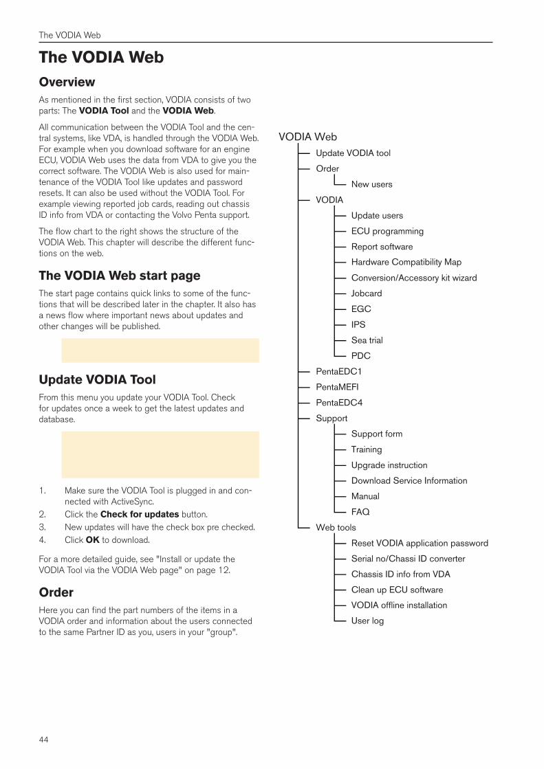
44
The VODIA Web
The VODIA WebOverviewAs mentioned in the first section, VODIA consists of two parts: The VODIA Tool and the VODIA Web.
All communication between the VODIA Tool and the cen-tral systems, like VDA, is handled through the VODIA Web. For example when you download software for an engine ECU, VODIA Web uses the data from VDA to give you the correct software. The VODIA Web is also used for main-tenance of the VODIA Tool like updates and password resets. It can also be used without the VODIA Tool. For example viewing reported job cards, reading out chassis ID info from VDA or contacting the Volvo Penta support.
The flow chart to the right shows the structure of the VODIA Web. This chapter will describe the different func-tions on the web.
The VODIA Web start pageThe start page contains quick links to some of the func-tions that will be described later in the chapter. It also has a news flow where important news about updates and other changes will be published.
Note! Read the news on the start page. Important information will always be published here.
Update VODIA ToolFrom this menu you update your VODIA Tool. Check for updates once a week to get the latest updates and database.
Important! Make sure that the VORP is on ex-ternal power and that you have the correct power settings before updating. See "Changing power settings" on page 10.
1. Make sure the VODIA Tool is plugged in and con-nected with ActiveSync.
2. Click the Check for updates button.3. New updates will have the check box pre checked.4. Click OK to download.
For a more detailed guide, see "Install or update the VODIA Tool via the VODIA Web page" on page 12.
OrderHere you can find the part numbers of the items in a VODIA order and information about the users connected to the same Partner ID as you, users in your "group".
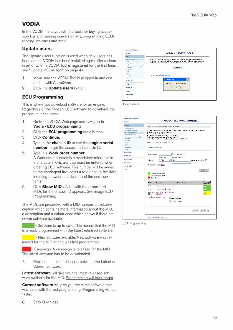
45
The VODIA Web
VODIAIn the VODIA menu you will find tools for buying acces-sory kits and running conversion kits, programming ECUs, reading job cards and more.
Update users
The Update users function is used when new users has been added, VODIA has been installed again after a clean reset or when a VODIA Tool is registered for the first time, see "Update VODIA Tool" on page 44.
1. Make sure the VODIA Tool is plugged in and con-nected with ActiveSync.
2. Click the Update users button.
ECU Programming
This is where you download software for an engine. Regardless of the chosen ECU software to download, the procedure is the same:
1. Go to the VODIA Web page and navigate to Vodia - ECU programming.
2. Click the ECU programming radio button.3. Click Continue�4. Type in the chassis ID or use the engine serial
number to get the associated chassis ID.5. Type in a Work order number.
A Work order number is a mandatory reference in 7 characters, 0-9, a-z, that must be entered when ordering ECU software. This number will be added to the contingent invoice as a reference to facilitate invoicing between the dealer and the end cus-tomer.
6. Click Show MIDs. A list with the associated MIDs for the chassis ID appears. See image ECU Programming.
The MIDs are presented with a MID number, a clickable caption which contains more information about the MID, a description and a colour code which shows if there are newer software available.
Green - Software is up to date. This means that the MID is already programmed with the latest released software.
Yellow - New software available. New software was re-leased for the MID after it was last programmed.
Red - Campaign. A campaign is released for the MID. The latest software has to be downloaded.
7. Replacement chain. Choose between the Latest or Current software:
Latest software will give you the latest released soft-ware available for the MID. Programming will take longer.
Current software will give you the same software that was used with the last programming. Programming will be faster.
8. Click Download.
ECU Programming
Update users
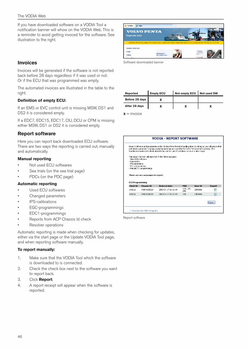
46
The VODIA Web
If you have downloaded software on a VODIA Tool a notification banner will whow on the VODIA Web. This is a reminder to avoid getting invoced for the software. See illustration to the right.
Report software
Software downloaded banner
Reported Empty ECU Not empty ECU Not used SW
Before 28 days xAfter 28 days x x x
x = invoice
Invoices
Invoices will be generated if the software is not reported back before 28 days regardless if it was used or not. Or if the ECU that was programmed was empty.
The automated invoices are illustrated in the table to the right.
Definition of empty ECU:
If an EMS or EVC control unit is missing MSW, DS1 and DS2 it is considered empty.
If a EDC7, EDC15, EDC17, CIU, DCU or CPM is missing either MSW, DS1 or DS2 it is considered empty.
Report software
Here you can report back downloaded ECU software. There are two ways the reporting is carried out, manually and automatically.
Manual reporting
• Not used ECU softwares• Sea trials (on the sea trial page)• PDCs (on the PDC page)
Automatic reporting
• Used ECU softwares• Changed parameters• IPS-calibrations• EGC-programmings• EDC1-programmings• Reports from ACP Chassis Id check• Resolver operations
Automatic reporting is made when checking for updates, either via the start page or the Update VODIA Tool page, and when reporting software manually.
To report manually:
1. Make sure that the VODIA Tool which the software is downloaded to is connected.
2. Check the check box next to the software you want to report back.
3. Click Report.4. A report receipt will appear when the software is
reported.
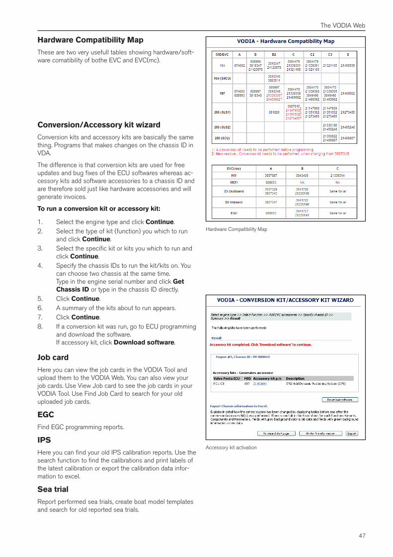
47
The VODIA Web
Accessory kit activation
Hardware Compatibility Map
Hardware Compatibility Map
These are two very usefull tables showing hardware/soft-ware comatibility of bothe EVC and EVC(mc).
Conversion/Accessory kit wizard
Conversion kits and accessory kits are basically the same thing. Programs that makes changes on the chassis ID in VDA.
The difference is that conversion kits are used for free updates and bug fixes of the ECU softwares whereas ac-cessory kits add software accessories to a chassis ID and are therefore sold just like hardware accessories and will generate invoices.
To run a conversion kit or accessory kit:
1. Select the engine type and click Continue.2. Select the type of kit (function) you which to run
and click Continue.3. Select the specific kit or kits you which to run and
click Continue.4. Specify the chassis IDs to run the kit/kits on. You
can choose two chassis at the same time. Type in the engine serial number and click Get Chassis ID or type in the chassis ID directly.
5. Click Continue.6. A summary of the kits about to run appears.7. Click Continue.8. If a conversion kit was run, go to ECU programming
and download the software. If accessory kit, click Download software.
Job card
Here you can view the job cards in the VODIA Tool and upload them to the VODIA Web. You can also view your job cards. Use View Job card to see the job cards in your VODIA Tool. Use Find Job Card to search for your old uploaded job cards.
EGC
Find EGC programming reports.
IPS
Here you can find your old IPS calibration reports. Use the search function to find the calibrations and print labels of the latest calibration or export the calibration data infor-mation to excel.
Sea trial
Report performed sea trials, create boat model templates and search for old reported sea trials.
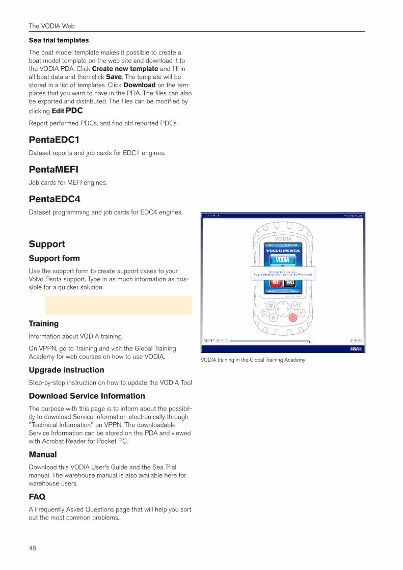
48
The VODIA Web
Sea trial templates
The boat model template makes it possible to create a boat model template on the web site and download it to the VODIA PDA. Click Create new template and fill in all boat data and then click Save. The template will be stored in a list of templates. Click Download on the tem-plates that you want to have in the PDA. The files can also be exported and distributed. The files can be modified by clicking Edit.PDC
Report performed PDCs, and find old reported PDCs.
PentaEDC1Dataset reports and job cards for EDC1 engines.
PentaMEFIJob cards for MEFI engines.
PentaEDC4Dataset programming and job cards for EDC4 engines.
VODIA training in the Global Training Academy
SupportSupport form
Use the support form to create support cases to your Volvo Penta support. Type in as much information as pos-sible for a quicker solution.
Note! Follow the instructions in the Support chap-ter in the end of this guide for quick support.
Training
Information about VODIA training.
On VPPN, go to Training and visit the Global Training Academy for web courses on how to use VODIA.
Upgrade instruction
Step-by-step instruction on how to update the VODIA Tool
Download Service Information
The purpose with this page is to inform about the possibil-ity to download Service Information electronically through "Technical Information" on VPPN. The downloadable Service Information can be stored on the PDA and viewed with Acrobat Reader for Pocket PC.
Manual
Download this VODIA User's Guide and the Sea Trial manual. The warehouse manual is also available here for warehouse users.
FAQ
A Frequently Asked Questions page that will help you sort out the most common problems.
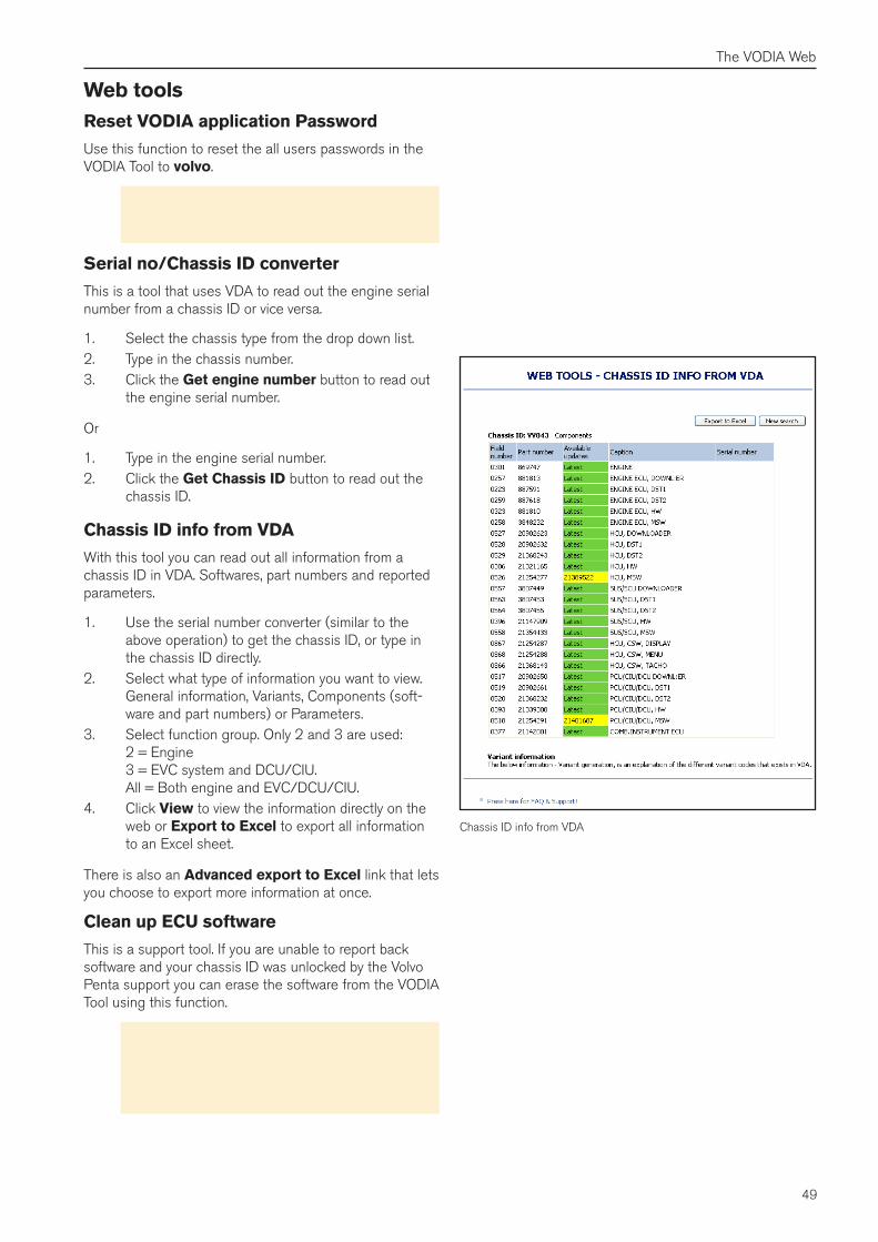
49
The VODIA Web
Chassis ID info from VDA
Web toolsReset VODIA application Password
Use this function to reset the all users passwords in the VODIA Tool to volvo.
Note! This option only resets the local passwords in the VODIA Tool. The password for VPPN will stay unchanged.
Serial no/Chassis ID converter
This is a tool that uses VDA to read out the engine serial number from a chassis ID or vice versa.
1. Select the chassis type from the drop down list.2. Type in the chassis number.3. Click the Get engine number button to read out
the engine serial number.
Or
1. Type in the engine serial number.2. Click the Get Chassis ID button to read out the
chassis ID.
Chassis ID info from VDA
With this tool you can read out all information from a chassis ID in VDA. Softwares, part numbers and reported parameters.
1. Use the serial number converter (similar to the above operation) to get the chassis ID, or type in the chassis ID directly.
2. Select what type of information you want to view. General information, Variants, Components (soft-ware and part numbers) or Parameters.
3. Select function group. Only 2 and 3 are used: 2 = Engine 3 = EVC system and DCU/CIU. All = Both engine and EVC/DCU/CIU.
4. Click View to view the information directly on the web or Export to Excel to export all information to an Excel sheet.
There is also an Advanced export to Excel link that lets you choose to export more information at once.
Clean up ECU software
This is a support tool. If you are unable to report back software and your chassis ID was unlocked by the Volvo Penta support you can erase the software from the VODIA Tool using this function.
Warning! Use this function ONLY if you've got your chassis ID and MID's unlocked by the Volvo Penta Support. Remember that you will be charged for the software that has been checked out.
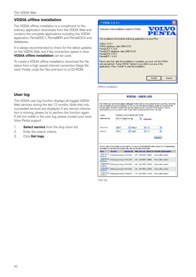
50
The VODIA Web
VODIA offline installation
The VODIA offline installation is a compliment to the ordinary application downloads from the VODIA Web and contains the complete applications including the VODIA application, PentaEDC1, PentaMEFI and PentaEDC4 and databases.
It is always recommended to check for the latest updates on the VODIA Web, but if the connection speed is slow VODIA offline installation can be used.
To create a VODIA offline installation, download the file below from a high speed internet connection (large file size). Finally, unzip the files and burn to a CD-ROM.
User log
Offline installation
User log
The VODIA user log function displays all logged VODIA Web services during the last 12 months. Note that only succeeded services are displayed. If any service informa-tion is missing, please try to perform the function again. If still not visible in the user log, please contact your local Volvo Penta support.
1. Select service from the drop down list.2. Enter the search criteria.3. Click Get logs.
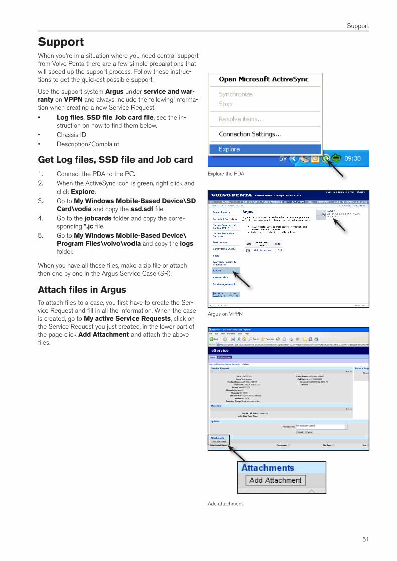
51
Support
Explore the PDA
SupportWhen you're in a situation where you need central support from Volvo Penta there are a few simple preparations that will speed up the support process. Follow these instruc-tions to get the quickest possible support.
Use the support system Argus under service and war-ranty on VPPN and always include the following informa-tion when creating a new Service Request:
• Log files, SSD file, Job card file, see the in-struction on how to find them below.
• Chassis ID• Description/Complaint
Get Log files, SSD file and Job card1. Connect the PDA to the PC.2. When the ActiveSync icon is green, right click and
click Explore.3. Go to My Windows Mobile-Based Device\SD
Card\vodia and copy the ssd�sdf file.4. Go to the jobcards folder and copy the corre-
sponding *�jc file.5. Go to My Windows Mobile-Based Device\
Program Files\volvo\vodia and copy the logs folder.
When you have all these files, make a zip file or attach then one by one in the Argus Service Case (SR).
Attach files in ArgusTo attach files to a case, you first have to create the Ser-vice Request and fill in all the information. When the case is created, go to My active Service Requests, click on the Service Request you just created, in the lower part of the page click Add Attachment and attach the above files.
Argus on VPPN
Add attachment